JP4309281B2 - Apparatus and method for protecting neurovascular bundles during cryosurgical treatment of the prostate - Google Patents
Apparatus and method for protecting neurovascular bundles during cryosurgical treatment of the prostateDownload PDFInfo
- Publication number
- JP4309281B2 JP4309281B2JP2003559412AJP2003559412AJP4309281B2JP 4309281 B2JP4309281 B2JP 4309281B2JP 2003559412 AJP2003559412 AJP 2003559412AJP 2003559412 AJP2003559412 AJP 2003559412AJP 4309281 B2JP4309281 B2JP 4309281B2
- Authority
- JP
- Japan
- Prior art keywords
- probe
- shaft
- gas
- prostate
- joule
- Prior art date
- Legal status (The legal status is an assumption and is not a legal conclusion. Google has not performed a legal analysis and makes no representation as to the accuracy of the status listed.)
- Expired - Fee Related
Links
- 238000000034methodMethods0.000titledescription62
- 210000002307prostateAnatomy0.000titledescription60
- 210000004977neurovascular bundleAnatomy0.000titledescription25
- 239000000523sampleSubstances0.000claimsdescription122
- 239000007789gasSubstances0.000claimsdescription77
- 238000010438heat treatmentMethods0.000claimsdescription70
- 238000001816coolingMethods0.000claimsdescription38
- 239000012530fluidSubstances0.000claimsdescription20
- 238000002347injectionMethods0.000claimsdescription17
- 239000007924injectionSubstances0.000claimsdescription17
- 239000000112cooling gasSubstances0.000claimsdescription16
- 238000005057refrigerationMethods0.000claimsdescription14
- 238000007599dischargingMethods0.000claimsdescription3
- 239000011810insulating materialSubstances0.000claimsdescription2
- 230000009977dual effectEffects0.000claims1
- 210000001519tissueAnatomy0.000description66
- 230000001575pathological effectEffects0.000description20
- 238000010586diagramMethods0.000description19
- 238000003780insertionMethods0.000description12
- 230000037431insertionEffects0.000description12
- 238000002604ultrasonographyMethods0.000description12
- 238000003384imaging methodMethods0.000description11
- 210000000056organAnatomy0.000description11
- 230000006378damageEffects0.000description9
- 238000007710freezingMethods0.000description9
- 230000008014freezingEffects0.000description9
- 239000001307heliumSubstances0.000description7
- 229910052734heliumInorganic materials0.000description7
- SWQJXJOGLNCZEY-UHFFFAOYSA-Nhelium atomChemical compound[He]SWQJXJOGLNCZEY-UHFFFAOYSA-N0.000description7
- 238000000315cryotherapyMethods0.000description6
- 238000013507mappingMethods0.000description6
- 210000003708urethraAnatomy0.000description6
- 238000002681cryosurgeryMethods0.000description5
- XKRFYHLGVUSROY-UHFFFAOYSA-NArgonChemical compound[Ar]XKRFYHLGVUSROY-UHFFFAOYSA-N0.000description4
- IJGRMHOSHXDMSA-UHFFFAOYSA-NAtomic nitrogenChemical compoundN#NIJGRMHOSHXDMSA-UHFFFAOYSA-N0.000description4
- 206010028980NeoplasmDiseases0.000description4
- 239000000463materialSubstances0.000description4
- 210000000664rectumAnatomy0.000description4
- 230000001568sexual effectEffects0.000description4
- 206010060862Prostate cancerDiseases0.000description3
- 238000002679ablationMethods0.000description3
- 239000004020conductorSubstances0.000description3
- 230000000694effectsEffects0.000description3
- 238000009413insulationMethods0.000description3
- 239000011159matrix materialSubstances0.000description3
- 230000008569processEffects0.000description3
- 208000023958prostate neoplasmDiseases0.000description3
- 206010004446Benign prostatic hyperplasiaDiseases0.000description2
- 208000004403Prostatic HyperplasiaDiseases0.000description2
- 208000000236Prostatic NeoplasmsDiseases0.000description2
- 230000009471actionEffects0.000description2
- 229910052786argonInorganic materials0.000description2
- 201000011510cancerDiseases0.000description2
- 238000004891communicationMethods0.000description2
- 238000013170computed tomography imagingMethods0.000description2
- 239000002872contrast mediaSubstances0.000description2
- 230000008878couplingEffects0.000description2
- 238000010168coupling processMethods0.000description2
- 238000005859coupling reactionMethods0.000description2
- 230000001066destructive effectEffects0.000description2
- 230000009986erectile functionEffects0.000description2
- 230000006870functionEffects0.000description2
- 238000012986modificationMethods0.000description2
- 230000004048modificationEffects0.000description2
- 229910052757nitrogenInorganic materials0.000description2
- 210000003899penisAnatomy0.000description2
- 238000002271resectionMethods0.000description2
- 238000001356surgical procedureMethods0.000description2
- 239000003570airSubstances0.000description1
- 210000004204blood vesselAnatomy0.000description1
- 210000004027cellAnatomy0.000description1
- 239000012141concentrateSubstances0.000description1
- 238000012790confirmationMethods0.000description1
- 238000013461designMethods0.000description1
- 230000001627detrimental effectEffects0.000description1
- 238000002059diagnostic imagingMethods0.000description1
- 230000001856erectile effectEffects0.000description1
- 210000003195fasciaAnatomy0.000description1
- 230000036541healthEffects0.000description1
- 239000012212insulatorSubstances0.000description1
- 229910052743kryptonInorganic materials0.000description1
- DNNSSWSSYDEUBZ-UHFFFAOYSA-Nkrypton atomChemical compound[Kr]DNNSSWSSYDEUBZ-UHFFFAOYSA-N0.000description1
- 239000007788liquidSubstances0.000description1
- 230000036210malignancyEffects0.000description1
- 230000003211malignant effectEffects0.000description1
- 239000002184metalSubstances0.000description1
- 238000012544monitoring processMethods0.000description1
- 210000000944nerve tissueAnatomy0.000description1
- 238000013021overheatingMethods0.000description1
- 230000002093peripheral effectEffects0.000description1
- 230000002062proliferating effectEffects0.000description1
- 238000012360testing methodMethods0.000description1
- 230000000451tissue damageEffects0.000description1
- 231100000827tissue damageToxicity0.000description1
- 238000012546transferMethods0.000description1
- 238000012285ultrasound imagingMethods0.000description1
- 229910052724xenonInorganic materials0.000description1
- FHNFHKCVQCLJFQ-UHFFFAOYSA-Nxenon atomChemical compound[Xe]FHNFHKCVQCLJFQ-UHFFFAOYSA-N0.000description1
Images


Classifications
- A—HUMAN NECESSITIES
- A61—MEDICAL OR VETERINARY SCIENCE; HYGIENE
- A61B—DIAGNOSIS; SURGERY; IDENTIFICATION
- A61B18/00—Surgical instruments, devices or methods for transferring non-mechanical forms of energy to or from the body
- A61B18/02—Surgical instruments, devices or methods for transferring non-mechanical forms of energy to or from the body by cooling, e.g. cryogenic techniques
- A—HUMAN NECESSITIES
- A61—MEDICAL OR VETERINARY SCIENCE; HYGIENE
- A61B—DIAGNOSIS; SURGERY; IDENTIFICATION
- A61B17/00—Surgical instruments, devices or methods
- A61B2017/00017—Electrical control of surgical instruments
- A61B2017/00022—Sensing or detecting at the treatment site
- A61B2017/00084—Temperature
- A—HUMAN NECESSITIES
- A61—MEDICAL OR VETERINARY SCIENCE; HYGIENE
- A61B—DIAGNOSIS; SURGERY; IDENTIFICATION
- A61B18/00—Surgical instruments, devices or methods for transferring non-mechanical forms of energy to or from the body
- A61B2018/00005—Cooling or heating of the probe or tissue immediately surrounding the probe
- A61B2018/00041—Heating, e.g. defrosting
- A—HUMAN NECESSITIES
- A61—MEDICAL OR VETERINARY SCIENCE; HYGIENE
- A61B—DIAGNOSIS; SURGERY; IDENTIFICATION
- A61B18/00—Surgical instruments, devices or methods for transferring non-mechanical forms of energy to or from the body
- A61B18/02—Surgical instruments, devices or methods for transferring non-mechanical forms of energy to or from the body by cooling, e.g. cryogenic techniques
- A61B2018/0231—Characteristics of handpieces or probes
- A61B2018/0262—Characteristics of handpieces or probes using a circulating cryogenic fluid
- A—HUMAN NECESSITIES
- A61—MEDICAL OR VETERINARY SCIENCE; HYGIENE
- A61B—DIAGNOSIS; SURGERY; IDENTIFICATION
- A61B18/00—Surgical instruments, devices or methods for transferring non-mechanical forms of energy to or from the body
- A61B18/02—Surgical instruments, devices or methods for transferring non-mechanical forms of energy to or from the body by cooling, e.g. cryogenic techniques
- A61B2018/0293—Surgical instruments, devices or methods for transferring non-mechanical forms of energy to or from the body by cooling, e.g. cryogenic techniques using an instrument interstitially inserted into the body, e.g. needle
- A—HUMAN NECESSITIES
- A61—MEDICAL OR VETERINARY SCIENCE; HYGIENE
- A61B—DIAGNOSIS; SURGERY; IDENTIFICATION
- A61B90/00—Instruments, implements or accessories specially adapted for surgery or diagnosis and not covered by any of the groups A61B1/00 - A61B50/00, e.g. for luxation treatment or for protecting wound edges
- A61B90/10—Instruments, implements or accessories specially adapted for surgery or diagnosis and not covered by any of the groups A61B1/00 - A61B50/00, e.g. for luxation treatment or for protecting wound edges for stereotaxic surgery, e.g. frame-based stereotaxis
- A61B90/11—Instruments, implements or accessories specially adapted for surgery or diagnosis and not covered by any of the groups A61B1/00 - A61B50/00, e.g. for luxation treatment or for protecting wound edges for stereotaxic surgery, e.g. frame-based stereotaxis with guides for needles or instruments, e.g. arcuate slides or ball joints
Landscapes
- Health & Medical Sciences (AREA)
- Surgery (AREA)
- Life Sciences & Earth Sciences (AREA)
- Nuclear Medicine, Radiotherapy & Molecular Imaging (AREA)
- Medical Informatics (AREA)
- Engineering & Computer Science (AREA)
- Biomedical Technology (AREA)
- Heart & Thoracic Surgery (AREA)
- Otolaryngology (AREA)
- Molecular Biology (AREA)
- Animal Behavior & Ethology (AREA)
- General Health & Medical Sciences (AREA)
- Public Health (AREA)
- Veterinary Medicine (AREA)
- Surgical Instruments (AREA)
- Thermotherapy And Cooling Therapy Devices (AREA)
Description
Translated fromJapanese本発明は前立腺の組織の冷凍切除中に神経血管束を保護する装置と方法に関する。さらに詳しく述べると、本発明は神経血管束の近くを加熱しながら前立腺内又は前立腺の近くの病的組織を冷凍切除温度まで冷却して、神経血管束を損傷しないように保護しながら病的組織を冷凍切除することに関する。 The present invention relates to an apparatus and method for protecting neurovascular bundles during cryoablation of prostate tissue. More particularly, the present invention cools pathologic tissue in or near the prostate while heating near the neurovascular bundle to the cryoablation temperature and protects the neurovascular bundle from damage. Related to cryoablation.
近年、病的組織を冷凍切除することは、前立腺癌や良性前立腺増殖症(「BPH」)の治療法としてますます普及している。病的組織の冷凍切除は一般に、X線、超音波、CT及びMRIなどの画像形成法を利用して除去処置を行う部位を確認し1又は2以上の冷凍プローブを選択された治療部位に挿入し、次いでその冷凍プローブの治療ヘッドを、その治療ヘッドの周りの組織を冷凍切除温度一般に約−40℃より低い温度まで到達させるのに十分に冷却することによって達成される。組織はこのように冷却されるとその機能と構造の完全性を失う。癌細胞は成長と増殖を停止しそして冷凍切除された腫瘍組織物質は、悪性腫瘍由来であろうと良性腫由来であろうとそののち身体に吸収される。したがって冷凍切除法は、前立腺の悪性腫瘍を治療し及びBPHの場合は前立腺容積を低下させるために利用できる。 In recent years, cryoablation of pathological tissue has become increasingly popular as a treatment for prostate cancer and benign prostatic hyperplasia (“BPH”). In general, cryoablation of pathological tissue is performed by using X-ray, ultrasound, CT, MRI, or other imaging methods to confirm the site to be removed and inserting one or more cryoprobes into the selected treatment site. And then cooling the treatment head of the cryoprobe sufficiently to allow the tissue around the treatment head to reach a cryoablation temperature, generally below about −40 ° C. When tissue is cooled in this way, it loses its functional and structural integrity. The cancer cells stop growing and proliferating, and the cryoablated tumor tissue material is then absorbed by the body, whether from malignant or benign tumors. Thus, cryoablation can be used to treat prostate malignancies and, in the case of BPH, reduce prostate volume.
しかし前立腺の冷凍外科切除治療の主な危険性と欠点は、治療部位の近くの非病的部位の機能と構造の完全性が部分的に又は完全に破壊されて被治療患者の健康と生活の質に対し有害な作用があるという危険があることである。 However, the main risks and disadvantages of cryosurgical resection of the prostate are that the function and structure integrity of the non-pathologic site near the treatment site is partially or completely destroyed, resulting in the health and life of the patient being treated. There is a danger of having a detrimental effect on quality.
非病的組織の損傷を抑制しながら病的前立腺組織を冷凍切除できる各種の装置と方法が提案されている。これらの装置と方法は大まかに次の二つの範疇に入る。すなわち、組織の近くで冷凍切除を行っている間その組織を過大冷却することを防止することによってその組織を保護する装置と方法、及び冷凍切除に使用する冷凍プローブの冷却作用を病的組織中に又は病的組織の近くにうまく集中させて非病的組織の不要な冷却を最小限にするため前記冷凍プローブを正確に配置できるようにする装置と方法の範疇に入る。 Various devices and methods that can cryoablate pathological prostate tissue while suppressing damage to non-pathological tissue have been proposed. These devices and methods fall roughly into the following two categories: That is, an apparatus and method for protecting a tissue by preventing overcooling while performing cryoablation near the tissue, and a cooling action of a cryoprobe used for cryoablation in a pathological tissue. It falls within the category of devices and methods that allow the cryoprobe to be accurately positioned to concentrate well in or near the pathological tissue to minimize unnecessary cooling of the non-pathological tissue.
前者の範疇の一例は、前立腺の部分を冷凍切除しているあいだ患者の尿道中に加熱装置又は加熱流体を導入して尿道及び尿道に隣接する組織を加熱し、近くの前立腺組織を冷凍切除温度まで冷却しながら尿道を損傷しないように保護するのに役立つ周知の方法である。 An example of the former category is the introduction of a heating device or fluid into the patient's urethra while cryosectioning a portion of the prostate to heat the urethra and tissue adjacent to the urethra, and cryoprosthesis temperature of nearby prostate tissue It is a well-known method that helps protect the urethra from being damaged while cooling down.
後者の範疇の一例はSchatzbergerの米国特許第6,142,991号が提供している。Schatzbergerは患者の前立腺を治療する高解像度の冷凍外科の方法と装置を記載しており、その方法と装置は、以下のステップ、すなわち(a)複数の冷凍外科プローブを前立腺に導入し、そのプローブは直径が実質的に小さくかつ前立腺を横切って分布させて前立腺の周縁に隣接するプローブの外側配列及び尿道前立腺部に隣接するプローブの内側配列を形成させ、(b)前記冷凍外科プローブ各々の末端にアイスボールを生成させて前立腺の組織セグメントを局所的に凍結させるステップを含んでいる。 An example of the latter category is provided by Schattberger US Pat. No. 6,142,991. Schatberger describes a high-resolution cryosurgical method and apparatus for treating a patient's prostate, the method and apparatus comprising the following steps: (a) introducing a plurality of cryosurgical probes into the prostate Is substantially smaller in diameter and distributed across the prostate to form an outer array of probes adjacent to the periphery of the prostate and an inner array of probes adjacent to the urethral prostate, and (b) the end of each cryosurgical probe Generating an ice ball to locally freeze the prostate tissue segment.
Schatzbergerの装置は、(a)直径が小さい複数の冷凍外科プローブであって、患者の器官中に挿入されかつアイスボールを生成して器官の選択された部分を局所的に凍結するプローブ、(b)冷凍外科プローブを通して挿入するための穴のネットを有する案内要素、及び(c)一組の画像を提供する画像形成装置であって、その画像は器官中の特定の深さに位置する特定の平面の情報を提供するためのものであり、前記画像は各々前記案内要素の穴のネットに関連するマークのネットを有し、そのマークは冷凍外科プローブが前記案内要素の前記穴を通して器官内の前記特定の深さまで導入されると形成できるアイスボールの位置を示す画像形成装置を備えている。 Schattberger's device is (a) a plurality of small diameter cryosurgical probes that are inserted into a patient's organ and generate ice balls to locally freeze selected portions of the organ; A) a guide element having a net of holes for insertion through a cryosurgical probe; and (c) an imaging device that provides a set of images, the images being located at a specific depth in the organ For providing planar information, wherein each of the images has a net of marks associated with the net of the hole in the guide element, the mark being inserted into the organ through the hole in the guide element by the cryosurgical probe An image forming apparatus showing the position of an ice ball that can be formed when introduced to the specific depth is provided.
したがってSchatzbergerの方法と装置によって、外科医は一組の冷凍切除プローブを前立腺内に比較的高い精度で配置し、そのプローブを操作して切除部位の近くの健康な組織の不測の望ましくない切除を大きく避けながら選択された組織を切除できる。 Thus, with Schattberger's method and apparatus, a surgeon places a set of cryoablation probes in the prostate with relatively high accuracy and manipulates the probes to greatly enhance the unexpected and undesired removal of healthy tissue near the ablation site. The selected tissue can be excised while avoiding it.
しかしSchatzbergerの方法又は他の公知の方法は、すべての症例で周縁組織の損傷を十分正確に防止することを立証していない。特に神経血管束、すなわちペニスが勃起する過程で非常に重要な血管や神経組織の多い前立腺領域は、従来の前立腺冷凍切除法で特に損傷を受けやすい。その神経血管束は、精のうのレベルから尿道まで前立腺の側背に位置しそして骨盤側壁にそって外側骨盤筋膜内に埋包されている。 However, Schattberger's method or other known methods have not proved to prevent peripheral tissue damage sufficiently accurately in all cases. In particular, the neurovascular bundle, that is, the prostatic region having a lot of blood vessels and nerve tissues which are very important in the process of erection of the penis, is particularly susceptible to damage by the conventional prostate cryoablation. The neurovascular bundle is located on the dorsal side of the prostate from the level of sperm to the urethra and is embedded in the lateral pelvic fascia along the pelvic sidewall.
神経血管束が損傷すると性交能力が失われることがある。活発な性生活を営んでいる性交能力がある患者は当然のことながら前立腺の冷凍外科治療の結果、性交能力が失われる危険に曝されることを嫌い、そしてこのような性交能力の喪失は、非冷凍外科法で前立腺癌を治療した症例でも起こるように従来の冷凍外科で治療した患者に不幸にも無視できない比率で起こる。 Damage to the neurovascular bundle can result in loss of intercourse ability. Patients with sexual ability who have an active sexual life naturally hate to be at risk of losing sexual ability as a result of prostate cryosurgery, and such loss of sexual ability is It occurs unfortunately in a non-negligible ratio in patients treated with conventional cryosurgery, as occurs in cases treated for prostate cancer with non-cryoscopic surgery.
したがって神経血管束を保護して前立腺の冷凍外科治療が患者の勃起能力を失わせる危険性を実質的に減らすか又は除きながら前立腺組織を冷凍切除できるようにする悪性前立腺腫瘍及び良性前立腺増殖症の治療法が広く要望されており、この方法は非常に有利である。 Therefore, malignant prostate tumors and benign prostatic hyperplasia that protect neurovascular bundles and allow cryo-resection of prostate tissue while substantially reducing or eliminating the risk of prostate cryosurgical treatment losing the patient's erectile abilities There is a widespread need for a treatment, which is very advantageous.
同様に、多くの類似の背景内で、冷凍切除を必要とする病的組織のごく近くの敏感でかつ重要な機能を有する健康組織を選択的に保護できるようにする装置と方法が広く要望されておりこの装置と方法は非常に有利である。 Similarly, there is a widespread need for an apparatus and method that allows selective protection of sensitive and important healthy tissue in close proximity to pathological tissue that requires cryoablation within many similar contexts. This apparatus and method is very advantageous.
発明の概要
本発明の一側面によって、(a)冷凍プローブの手術チップを前立腺内の病的部位の近くに配置し;(b)加熱プローブを神経血管束の近くに配置し;次いで(c)冷凍プローブの手術チップを冷凍切除温度まで冷却しながら加熱プローブを加熱して、加熱プローブの近くの神経血管束の組織が凍結するのを防いで少なくとも神経血管束の部分の損傷を防止しながら手術チップの近くの病的組織を冷凍切除することを含んでなる少なくとも神経血管束の部分を保護しながら前立腺の組織を冷凍切除する方法が提供される。SUMMARY OF THE INVENTION According to one aspect of the invention, (a) a cryoprobe surgical tip is placed near a pathological site in the prostate; (b) a heated probe is placed near a neurovascular bundle; and (c) Heating the heating probe while cooling the surgical tip of the cryoprobe to the cryoablation temperature, preventing the tissue of the neurovascular bundle near the heated probe from freezing, and at least preventing damage to the portion of the neurovascular bundle A method of cryoablating prostate tissue while protecting at least a portion of a neurovascular bundle comprising cryoablating pathological tissue near the tip is provided.
以下に説明する本発明の好ましい実施態様のさらなる特徴によって、本発明の前記方法はさらに、画像形成法を利用して患者の前立腺領域のマッピングを行って冷凍切除すべき病的部位の位置を確認しそして冷凍切除しないようにかつ凍結によって損傷しないように保護すべき神経血管束の位置を確認することを含んでいる。好ましくは、案内要素を使用して、前記位置を確認された病的組織の近くへの冷凍プローブの配置を案内しかつ前記位置を確認された神経血管束の近くへの加熱プローブの配置を案内する。 According to further features in preferred embodiments of the invention described below, the method of the invention further utilizes imaging to map the prostate region of the patient to determine the location of the pathological site to be cryoablated. And identifying the location of the neurovascular bundle to be protected from cryoablation and from being damaged by freezing. Preferably, a guide element is used to guide the placement of the cryoprobe near the located pathological tissue and guide the placement of the heated probe near the located neurovascular bundle To do.
記載された好ましい実施態様のさらに別の特徴によって、前記画像形成法はCT画像形成法、X線画像形成法及び超音波画像形成法からなる群から選択される。好ましい一実施態様によれば、超音波プローブを患者の直腸に挿入することによって前立腺の超音波画像を得ることができる。 According to still further features in the described preferred embodiments the imaging method is selected from the group consisting of CT imaging methods, X-ray imaging methods and ultrasonic imaging methods. According to one preferred embodiment, an ultrasound image of the prostate can be obtained by inserting an ultrasound probe into the patient's rectum.
本発明の別の側面によって、シャフトと遠位手術チップを備え、そのチップはチップの周りの組織を冷凍切除温度まで冷却してその組織を冷凍切除するように作動し、そしてそのシャフトはシャフトに隣接する組織を冷凍切除されないようにかつ凍結によって損傷されないように保護するよう設計され製作されている冷凍プローブが提供される。 In accordance with another aspect of the invention, a shaft and a distal surgical tip are provided, the tip is operative to cool the tissue around the tip to a cryoablation temperature and cryoablate the tissue, and the shaft is attached to the shaft. A cryoprobe is provided that is designed and fabricated to protect adjacent tissue from being cryoablated and from being damaged by freezing.
以下に述べる本発明の好ましい実施態様のさらなる特徴によって、シャフトは、シャフト内の低温領域を、シャフトに隣接する組織と直接接触するシャフトの外側部分から断熱する働きをする断熱要素を含んでいる。その断熱要素は少なくとも部分真空を含む断熱シースとして製造できる。 According to further features in preferred embodiments of the invention described below, the shaft includes a thermal insulation element that serves to insulate the cold region within the shaft from the outer portion of the shaft that is in direct contact with the tissue adjacent the shaft. The insulating element can be manufactured as an insulating sheath containing at least a partial vacuum.
以下に述べる本発明の好ましい実施態様のさらなる特徴によって、シャフトは加熱要素を含み、その加熱要素は電気抵抗加熱要素、マイクロ波加熱要素、電子加熱要素又は流体加熱モジュールである。 According to further features in preferred embodiments of the invention described below, the shaft includes a heating element, the heating element being an electrical resistance heating element, a microwave heating element, an electronic heating element or a fluid heating module.
以下に述べる本発明の好ましい実施態様のさらなる特徴によって、上記流体加熱モジュールは、流体をシャフト内の容積部分に送達する第一流路を備え、さらにその流体を前記シャフトの前記容積部分から排出する第二流路を備えている。その第一流路は、予め加熱された流体を前記シャフトの部分に送達するか又は圧縮加熱ガスを第一ジュール−トムソンオリフィスに送達するように作動する。 According to further features in preferred embodiments of the invention described below, the fluid heating module includes a first flow path for delivering fluid to a volume portion in the shaft and further discharging the fluid from the volume portion of the shaft. It has two flow paths. The first flow path operates to deliver preheated fluid to the portion of the shaft or to deliver compressed heated gas to the first Joule-Thomson orifice.
以下に述べる本発明の好ましい実施態様のさらなる特徴によって、シャフトは第一ジュール−トムソンオリフィスを有しそして手術チップは第二ジュール−トムソンオリフィスを有している。冷凍プローブは第一ガス注入流路と第二ガス注入流路を有し、その第一ガス注入流路は圧縮加熱ガスを第一ジュール−トムソンオリフィスに送達するように作動し、一方第二ガス注入流路は圧縮冷却ガスを第二ジュール−トムソンオリフィスに送達する。 According to further features in preferred embodiments of the invention described below, the shaft has a first Joule-Thomson orifice and the surgical tip has a second Joule-Thomson orifice. The refrigeration probe has a first gas injection channel and a second gas injection channel, the first gas injection channel is operative to deliver the compressed heated gas to the first Joule-Thomson orifice, while the second gas The injection channel delivers compressed cooling gas to the second Joule-Thomson orifice.
本発明のさらに別の側面によって、(a)冷凍プローブの手術チップを冷凍切除温度まで冷却して手術チップに隣接する組織を冷凍切除し;そして(b)同時にシャフトの部分を加熱して、シャフトに隣接する組織の凍結を防いでシャフトに隣接する組織を保護しながら手術チップに隣接する組織を冷凍切除することを含んでなる冷凍プローブのシャフトに隣接する組織を保護しながら前記冷凍プローブの手術チップに隣接する組織を冷凍切除する方法が提供される。 According to yet another aspect of the invention, (a) the surgical tip of the cryoprobe is cooled to cryoablation temperature to cryoablate tissue adjacent to the surgical tip; and (b) the shaft portion is simultaneously heated to The cryoprobe operation while protecting the tissue adjacent to the shaft of the cryoprobe comprising cryoablating the tissue adjacent to the surgical tip while preventing freezing of the tissue adjacent to the shaft and protecting the tissue adjacent to the shaft A method for cryoablating tissue adjacent to a tip is provided.
シャフトの部分、好ましくはシャフトの外壁に隣接する外側部分を、電気抵抗加熱、マイクロ波加熱、電子加熱、予め加熱された流体の循環及びジュール−トムソン加熱で加熱することができる。 A portion of the shaft, preferably the outer portion adjacent to the outer wall of the shaft, can be heated by electrical resistance heating, microwave heating, electronic heating, circulating preheated fluid and Joule-Thomson heating.
本発明は、重要な機能を有する健康な組織の領域を、その近くの病的組織を冷凍切除している間、保護する装置と方法を提供することによって現在知られている配置構成の欠点をうまく処理する。 The present invention overcomes the disadvantages of currently known arrangements by providing an apparatus and method that protects an area of healthy tissue having important functions while cryoablating the nearby pathological tissue. Handle well.
本発明はさらに、近くの前立腺組織を冷凍切除している間神経血管束を保護して、患者の勃起機能が前立腺の冷凍切除治療で失われる確率を実質的に減らすか又は除く装置と方法を提供することによって現在知られている配置構成の欠点をうまく処理する。 The present invention further provides an apparatus and method that protects neurovascular bundles while cryoablating nearby prostate tissue to substantially reduce or eliminate the probability that a patient's erectile function will be lost in prostate cryoablation. By providing, it successfully addresses the shortcomings of currently known arrangements.
本明細書で使用される技術用語と科学用語はすべて、特に断らない限り、本発明の属する技術分野の当業者が共通して理解しているのと同じ意味を持っている。本明細書に記載されているのと類似の又は均等の方法と材料は本発明を実施又は試験するのに使用できるが、適切な方法と材料は以下に述べる。争いが生じた場合、定義を含めて本特許明細書が基準である。さらに本明細書の材料、方法及び実施例は例示することだけを目的とし本発明を限定するものではない。 Unless defined otherwise, all technical and scientific terms used herein have the same meaning as commonly understood by one of ordinary skill in the art to which this invention belongs. Although methods and materials similar or equivalent to those described herein can be used in the practice or testing of the present invention, suitable methods and materials are described below. In case of conflict, the patent specification, including definitions, will control. In addition, the materials, methods, and examples provided herein are for purposes of illustration only and are not intended to limit the invention.
本発明の方法及びシステムを実行することは、選択されたタスク又はステップを、手動操作で、自動的に又はそれらを組み合わせて実行又は完了することを含んでいる。さらに本発明の方法とシステムの好ましい実施態様の実際の機器や装置によって、いくつもの選択されたステップを、いずれかのファームウェアのいずれかのオペレーティングシステムのハードウェア又はソフトウェア又はそれらの組合せによって実行できる。例えば本発明の選択されたステップはチップ又は回路のようなハードウェアとして実施できる。本発明の選択されたステップは、コンピュータが適切なオペレーティングシステムを使って実行する複数のソフトウェアの命令のようなソフトウェアとして実施される。いずれにしろ、本発明の方法とシステムの選択されたステップは、データプロセッサ例えば複数の命令を実行する計算プラットホームで実行されるといえる。 Performing the method and system of the present invention includes performing or completing selected tasks or steps manually, automatically, or a combination thereof. Further, depending on the actual equipment and apparatus of the preferred embodiment of the method and system of the present invention, any number of selected steps can be performed by any operating system hardware or software or any combination thereof in any firmware. For example, selected steps of the present invention can be implemented as hardware such as a chip or circuit. Selected steps of the present invention are implemented as software, such as a plurality of software instructions that a computer executes using a suitable operating system. In any case, selected steps of the method and system of the present invention can be said to be performed on a data processor, eg, a computing platform that executes a plurality of instructions.
図面の説明
本明細書では本発明を単に例示し図面を参照して説明する。特に詳細な図面を参照して、示されている詳細は例示として本発明の好ましい実施態様を例示考察することだけを目的としており、本発明の原理や概念の側面の最も有用でかつ容易に理解される説明であると考えられるものを提供するために提示していることを強調するものである。この点について、本発明を基本的に理解するのに必要である以上に詳細に本発明の構造の詳細は示さないが、図面について行う説明によって本発明のいくつもの形態を実施する方法は当業者には明らかになるであろう。DESCRIPTION OF THE DRAWINGS The present description is merely illustrative of the invention and will be described with reference to the drawings. In particular, with reference to the detailed drawings, the details shown are for the purpose of illustrating only preferred embodiments of the invention by way of example and are the most useful and easily understood aspects of the principles and concepts of the invention. It is emphasized that it is presented to provide what is believed to be the explanation given. In this regard, details of the structure of the present invention are not shown in more detail than is necessary for a basic understanding of the present invention, but those skilled in the art will understand how to implement several forms of the present invention by way of the description given with reference to the drawings. Will become clear.
図1は従来技術の方法による典型的な冷凍プローブの概略図である。
図2は従来技術の方法による複数の冷凍外科プローブを共通のガス源に接続するマニホルド構造の概略図である。
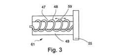
図3は従来技術の方法による予備冷却要素の別の配置構成の概略図である。
図4は従来技術の方法による超音波プローブ及び複数の冷凍プローブの患者身体への挿入を案内する案内要素を備えた装置の概略図である。
図5は従来技術の方法による図4に示す装置の使用法を示す概略図である。
図6は従来技術の方法による図4に示す装置を使用する際のさらなるステップを示す概略図である。
図7は本発明の一実施態様による前立腺治療装置の概略図である。
図8は図7に示す治療装置の追加の図である。
図9は本発明の一実施態様による前立腺の腫瘍などの器官の一部を冷凍切除する方法の推薦される方法の概略フローチャートである。
図10は本発明の追加の好ましい一実施態様による前立腺治療装置の概略図である。
図11は本発明の一実施態様の冷凍治療ヘッドと加熱可能なシャフトを有する冷凍プローブの概略図である。
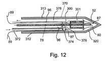
図12は本発明の一実施態様による冷凍治療ヘッドと加熱可能なシャフトを有する別の構造の冷凍プローブの概略図である。
図13は本発明の一実施態様による絶縁されたシャフトを有する冷凍プローブの概略図である。FIG. 1 is a schematic diagram of a typical cryoprobe according to the prior art method.
FIG. 2 is a schematic view of a manifold structure connecting a plurality of cryosurgical probes to a common gas source according to prior art methods.
FIG. 3 is a schematic diagram of another arrangement of precooling elements according to the prior art method.
FIG. 4 is a schematic view of an apparatus comprising a guiding element for guiding the insertion of an ultrasonic probe and a plurality of cryoprobes into a patient body according to a prior art method.
FIG. 5 is a schematic diagram illustrating the use of the apparatus shown in FIG. 4 according to the prior art method.
FIG. 6 is a schematic diagram showing further steps in using the apparatus shown in FIG. 4 according to a prior art method.
FIG. 7 is a schematic view of a prostate treatment device according to an embodiment of the present invention.
FIG. 8 is an additional view of the treatment device shown in FIG.
FIG. 9 is a schematic flow chart of a recommended method of a method for cryoablating a portion of an organ, such as a prostate tumor, according to one embodiment of the present invention.
FIG. 10 is a schematic diagram of a prostate treatment device according to an additional preferred embodiment of the present invention.
FIG. 11 is a schematic view of a cryoprobe having a cryotherapy head and a heatable shaft according to an embodiment of the present invention.
FIG. 12 is a schematic view of another structure of a cryoprobe having a cryotherapy head and a heatable shaft according to an embodiment of the present invention.
FIG. 13 is a schematic view of a cryoprobe having an insulated shaft according to one embodiment of the present invention.
本発明は、健康な組織を損傷しないように保護しながら近くの病的組織を冷凍切除する装置と方法の発明である。さらに詳しく述べると本発明は、神経血管束領域などの前立腺中又は前立腺の近くの第一選択組織領域を加熱しながら良性の又は悪性の腫瘍組織などの前立腺中又は前立腺の近くの第二選択組織領域を冷凍切除温度まで冷却して、選択された病的組織を冷凍切除しながら神経血管束などの選択された健康な組織を保護することに関する。本発明は、前立腺組織を冷凍手術中、神経血管束を保護して被治療患者のペニスの勃起機能に対する前立腺冷凍外科手術の副作用の危険を減らすために使用できる。 The present invention is an invention of an apparatus and method for cryoablating nearby diseased tissue while protecting healthy tissue from damage. More particularly, the invention relates to a second selected tissue in or near the prostate, such as a benign or malignant tumor tissue, while heating a first selected tissue region in or near the prostate, such as a neurovascular bundle region. It relates to cooling a region to cryoablation temperature to protect selected healthy tissue such as a neurovascular bundle while cryoablating selected pathological tissue. The present invention can be used to protect neurovascular bundles during cryosurgery of prostate tissue and reduce the risk of side effects of prostate cryosurgery on the erectile function of the treated patient's penis.
本発明の少なくとも一つの実施態様を詳細に説明する前に、本発明はその用途を以下の説明に記載されているか又は図面に例示されている要素の構造の詳細と配置にその用途が限定されないと解すべきである。本発明にはその外の実施態様があり又は種々の方法で実行もしくは実施できる。また本明細書に使用される用語と語句は説明を目的とするものであり本発明を限定するとみなすべきではないと解すべきである。 Before describing at least one embodiment of the present invention in detail, the present invention is not limited in its application to the structural details and arrangement of elements described in the following description or illustrated in the drawings. Should be understood. The invention has other embodiments or can be practiced or carried out in various ways. It should also be understood that the terms and phrases used herein are for illustrative purposes and should not be considered limiting of the present invention.
以下の説明を一層明確にするため最初に以下の用語と語句を説明する。 To make the following explanation clearer, the following terms and phrases are explained first.
語句「熱交換配置構成」は、本明細書で使用する場合、「熱交換器」として伝統的に知られている要素の配置構成すなわち熱を一つの要素から別の要素へ移行しやすくする方式で設置された要素の配置構成を意味する。要素の「熱交換配置構成」の例としては、要素間の熱交換を容易に行えるようにするため使用される多孔質マトリックス、多孔質マトリックス内にトンネルを組み合わせた構造体、多孔質マトリックス内に渦巻管路を含む構造体、第二管路の周りに巻きついた第一管路を含む構造体、一つの管路内に別の管路を有する構造体又はこれらに類似の構造体がある。 The phrase “heat exchange arrangement” as used herein refers to an arrangement of elements traditionally known as “heat exchangers”, ie, a scheme that facilitates the transfer of heat from one element to another. Means the arrangement configuration of the elements installed in. Examples of “heat exchange arrangements” of elements include a porous matrix used to facilitate heat exchange between elements, a structure combining tunnels in a porous matrix, and in a porous matrix There is a structure including a spiral line, a structure including a first line wound around a second line, a structure having another line in one line, or a similar structure. .
語句「ジュール−トムソン熱交換器」は、本明細書で使用するとき、一般に低温冷却又は加熱を行うのに使う装置を意味し、その装置は、ガスが高圧に保持されているその装置の第一領域からガスを膨張させて低圧にすることができるその装置の第二領域に、ガスを送る。ジュール−トムソン熱交換器は簡単な管路であるか又はガスが装置の高圧の第一領域から装置の低圧の第二領域へ移動するオリフィスを備えている。ジュール−トムソン熱交換器はさらに、熱交換配置構成例えばガスを装置の第一領域内で冷却したのち装置の第二領域に入れて膨張させるために使用する熱交換配置構成を備えている。 The phrase “Joule-Thomson heat exchanger”, as used herein, generally refers to a device used to perform cryogenic cooling or heating, which device is the first of the device in which the gas is held at a high pressure. The gas is sent to a second region of the device where the gas can be expanded from one region to a low pressure. The Joule-Thompson heat exchanger is a simple line or comprises an orifice through which gas travels from a high pressure first region of the device to a low pressure second region of the device. The Joule-Thompson heat exchanger further comprises a heat exchange arrangement, such as a heat exchange arrangement used to cool the gas in the first region of the device and then expand it into the second region of the device.
語句「冷却ガス」は本明細書で使用する場合、ジュール−トムソン熱交換器を通過するときより低い温度になる特性を有するガスを意味する。当該技術分野でよく知られているように、アルゴン、窒素、空気、クリプトン、CO2、CF4、キセノン及びN2Oなどのガス並びに他の各種ガスがジュール−トムソン熱交換器の高圧領域から低圧領域へ移動すると、これらのガスは冷却し或程度液化して液化ガスの低温プールをつくる。この工程はジュール−トムソン熱交換器自体を冷却しかつその熱交換器に接触する熱伝導性物質も冷却する。ジュール−トムソン熱交換器を通過するとき一層低温になる特性を有するガスは以後「冷却ガス」と呼称する。The phrase “cooling gas” as used herein means a gas that has the property of lower temperatures when passing through a Joule-Thomson heat exchanger. As is well known in the art, gases such as argon, nitrogen, air, krypton, CO2 , CF4 , xenon and N2 O as well as various other gases come from the high pressure region of the Joule-Thomson heat exchanger. When moving to the low pressure region, these gases cool or liquefy to create a cold pool of liquefied gas. This process cools the Joule-Thomson heat exchanger itself and also the thermally conductive material in contact with the heat exchanger. A gas that has the property of becoming colder when passing through a Joule-Thomson heat exchanger is hereinafter referred to as "cooling gas".
語句「加熱ガス」は本明細書で使用する場合、ジュール−トムソン熱交換器を通過するときより高い温度になる特性を有するガスを意味する。ヘリウムがこの特性を有するガスの一例である。ヘリウムが高圧領域から低圧領域へ移動すると加熱される。したがってヘリウムにジュール−トムソン熱交換器を通過させるとヘリウムを加熱する作用が起こり、ジュール−トムソン熱交換器自体を加熱しその熱交換器に接触する熱伝導性物質も加熱する。この特性を有するヘリウムなどのガスは以後「加熱ガス」と呼ぶ。 The phrase “heated gas” as used herein means a gas that has the property of becoming a higher temperature when passing through a Joule-Thomson heat exchanger. Helium is an example of a gas having this property. As helium moves from the high pressure region to the low pressure region, it is heated. Therefore, when helium is passed through the Joule-Thomson heat exchanger, the action of heating the helium occurs, and the Joule-Thomson heat exchanger itself is heated and the heat conductive material contacting the heat exchanger is also heated. A gas such as helium having this characteristic is hereinafter referred to as a “heating gas”.
用語「ジュール−トムソン冷却器」は本明細書で使用する場合、冷却に使用するジュール−トムソン熱交換器を意味する。用語「ジュール−トムソン加熱器」は本明細書で使用する場合、加熱に使うジュール−トムソン熱交換器を意味する。 The term “Joule-Thomson cooler” as used herein means a Joule-Thomson heat exchanger used for cooling. The term “Joule-Thomson heater” as used herein means a Joule-Thomson heat exchanger used for heating.
以下に記載する各種図面を考察する際、同じ番号は同じ部品を意味する。
図7−13に示す本発明をより十分に理解するために、まず図1−6に示す従来(すなわち従来技術)の冷凍外科装置と冷凍外科治療法の構造と作動について述べる。When considering the various drawings described below, the same numbers refer to the same parts.
To better understand the invention shown in FIGS. 7-13, the structure and operation of the conventional (ie, prior art) cryosurgical apparatus and cryosurgical method shown in FIGS. 1-6 will be described first.
図1−3に示す従来技術の方法による冷凍外科装置は複数の冷凍外科プローブを備えている。 The cryosurgical apparatus according to the prior art method shown in FIGS. 1-3 comprises a plurality of cryosurgical probes.
図1は従来技術の方法による典型的な冷凍プローブの概略図を示す。
図1は、患者の組織を凍結するジュール−トムソン冷却器を有する手術チップ52及び外科医が保持する保持部材72を備えた冷凍プローブ50を示す。図1に示すように手術チップ52は、その末端に配置されたオリフィス80に高圧ガスを提供するため手術チップを通って延びる少なくとも一つの流路78を有し、そのオリフィス80は手術チップ52を冷却してその末端90にアイスボールを生成するためそれを通じて高圧冷却ガスを送る。FIG. 1 shows a schematic diagram of a typical cryoprobe according to the prior art method.
FIG. 1 shows a
アルゴンなどの高圧冷却ガスはオリフィス80を通過させて膨張させると液化して手術チップ52のチャンバー82内に低温プールを形成し、その低温プールは手術チップ52の表面84を効果的に冷却する。手術チップ52の表面84は、手術チップの末端90にアイスボールを形成できるように金属などの熱伝導性材料で製造することが好ましい。 A high pressure cooling gas such as argon liquefies when expanded through the
あるいは逆ジュール−トムソン法にしたがってヘリウムなどの高圧加熱ガスを使用して手術チップ52を加熱し、冷却−加熱のサイクルで治療を行えるようにすることができ、そしてさらにプローブを患者の身体から引き出すときプローブが組織に粘着するのを防いで必要なときに迅速に引き出せるようにすることができる。 Alternatively, the
ヘリウムなどの高圧加熱ガスはオリフィス80を通過して膨張するとチャンバー82を加熱して手術チップ52の表面84を加熱する。 When a high pressure heated gas such as helium expands through the
手術チップ52は、ガスを手術チップ52から大気中に引き抜くため中を通って延びる少なくとも一つの排気流路96を備えている。 The
図1に示すように、保持部材72は流路78を通じて流れるガスを予備冷却する熱交換器を備えている。具体的に述べると、流路78の上部は排気流路96の周りに巻きつけられた螺旋チューブ76の形態であり、その螺旋チューブはチャンバー98内に収納されている。したがって流路96を通じて引き抜かれるガスは、螺旋チューブ76を通じて流入するガスを予備冷却する。 As shown in FIG. 1, the holding
さらに図1に示すように、保持部材72は、熱交換器を外部環境から断熱する断熱体92を備えている。 Further, as shown in FIG. 1, the holding
さらに手術チップ52はチャンバー82内の温度を感知する少なくとも一つの熱センサ87を備え、そのワイヤ89が排気流路96又は専用の通路(図示せず)を通じて延びている。プローブ50はさらに1又は2以上の外部熱センサ86を備え、そのセンサは、手術チップ52を冷却することによって周りの組織にもたらされた温度を報告できるように手術チップ52からいくらか距離を置いて配置することが好ましい。 The
さらに保持部材72は外科医がプローブ50の作動を手動操作で制御するため使う複数のスイッチ99を備えている。このようなスイッチは、オン/オフ、加熱、冷却、及び流入流路70を冷却ガスもしくは加熱ガスの入っている適切な外部ガス容器に選択的にかつ制御可能に連通させることによる加熱と冷却の予め定められたサイクルを提供できる。 The retaining
ここで図2に移るが、図2は従来技術の方法によって複数の冷凍外科プローブ50を共通ガス源に接続するガス分布モジュールの概略図を示す。 Turning now to FIG. 2, FIG. 2 shows a schematic diagram of a gas distribution module that connects a plurality of
図2は、各冷凍外科プローブ50がハウジング要素58上の接続部位56に可撓性接続ライン54を通じて好ましくは連結要素51によって接続されているガス分布モジュール40を示す。冷凍外科プローブ50は接続部位56に着脱自在に接続されている。 FIG. 2 shows a
排気流路96は好ましくは接続ライン54を通じて延びその結果送出ガスは連結要素51又は他の適切な部位例えばマニホルド55(以下の説明を参照のこと)に位置する開口を通じて排出される。好ましくはライン54はさらに、電気信号を熱センサやスイッチ(図示せず)に送る電線を備えている。 The
各冷凍外科プローブ50は、ハウジング58内に収容されているマニホルド55と流体連通しており、そしてマニホルド55は流入する高圧ガスをライン57を通じて冷凍外科プローブ50に分布させる。 Each
図に示すようにハウジング58は、ガスチューブ(図示せず)を含む可撓性ケーブル60を通じてコネクタ62に接続され、そのコネクタ62は装置を高圧ガス源と電源に接続する。 As shown, the
装置はさらに電源と冷凍外科プローブ50の間の電気連通を行うためケーブル60とハウジング58を通って延びる電線(図示せず)を備えている。 The apparatus further includes an electrical wire (not shown) extending through
好ましくはハウジング58は冷凍外科プローブ50に流れる高圧ガスを予備冷却する一般に番号61で示す予備冷却要素を備えている。予備冷却要素61は好ましくはジュール−トムソン冷却器であり、この冷却器はチャンバー49内に収容された管状部材48を有し、その管状部材48は、高圧ガスを通過させてチャンバー49を冷却して、管状部材48を通じてマニホルド55に流入するガスを冷却するオリフィス59を備えている。 Preferably, the
ここで図3に移るが、図3は従来技術の方法による予備冷却要素61の別の配置構成を示し、そこでは管状部材48は、その部材とチャンバー49内冷却ガスとの間の接触面積を増やすため円筒形要素47の周りに巻きつけられた螺旋チューブの形態である。 Turning now to FIG. 3, FIG. 3 shows another arrangement of the precooling
さらに別の配置構成(図示せず)によれば、ハウジング58は第一高圧ガスをマニホルド55に供給する第一管状部材及び第二高圧ガスを予備冷却要素61に供給する第二管状部材を備えている。このような管状部材を通じて流れているガスを冷却及び/又は加熱するため組み合わせたガスを使用できる。 According to yet another arrangement (not shown), the
あるいは液体窒素のような冷凍流体を使用してハウジング58を通って流れるガスを予備冷却できる。あるいは電気予備冷却要素を使用してガスを予備冷却できる。 Alternatively, a refrigeration fluid such as liquid nitrogen can be used to precool the gas flowing through the
好ましくは熱センサ(図示せず)をケーブル60とマニホルド55の中に配置してその中を流れるガスの温度を測定する。 A thermal sensor (not shown) is preferably placed in
ここで図4〜6に移るが、図4〜6は画像形成装置を使用して患者の被治療器官例えば前立腺の三次元グリッドを形成する従来技術の方法と装置を示し、その三次元グリッドは、三次元の形態の器官に関する情報を提供する働きをする。次に上記グリッドの提供した情報に従って、一組の冷凍外科プローブの各々を器官内の特定の深さまで挿入する。 Turning now to FIGS. 4-6, FIGS. 4-6 illustrate a prior art method and apparatus for forming a three-dimensional grid of a patient's treated organ, eg, prostate, using an imaging device, the three-dimensional grid being It serves to provide information about organs in three-dimensional form. Then, according to the information provided by the grid, each of a set of cryosurgical probes is inserted to a specific depth within the organ.
図4は、超音波プローブ及び複数の冷凍プローブの患者身体への挿入を案内する案内要素を備えた従来技術の方法による装置の概略図である。 FIG. 4 is a schematic view of an apparatus according to the prior art method comprising a guiding element for guiding the insertion of an ultrasound probe and a plurality of cryoprobes into a patient body.
図4に示すように、超音波プローブ130は患者の直腸に挿入するためのものであり、超音波プローブ130はハウジング要素128内に収容されている。案内要素115が接続アーム126によってハウジング要素128に接続されている。図に示すように案内要素115は穴120のネットを有するプレート110の形態であり、各穴はそれを通して冷凍外科プローブを挿入するためのものである。隣接する穴120の各対の間の距離は好ましくは約2mm〜約5mmである。 As shown in FIG. 4, the
ここで図4に示す装置の使用法を示す概略図である図5に移る。
図5に示すように超音波プローブ130が患者の直腸3内に特定の深さ113まで導入される。得られた超音波画像114上にマーク112のネットが提供され、その画像114上のマーク112のネットは、案内要素115上の穴120のネットに正確に合致している。Turning now to FIG. 5, which is a schematic diagram illustrating the use of the apparatus shown in FIG.
As shown in FIG. 5, an
したがって画像114上のマーク112は、穴120を通じて患者の前立腺2に挿入された冷凍外科プローブの末端に形成されるアイスボールの中心の正確な位置を示し、画像114は冷凍外科プローブが前立腺2中に挿入された特定の深さ113に関連している。 Thus, the
図5に示すように超音波プローブ130を直腸3の各種の深さ113まで徐々に導入して一組の画像114をつくり、各画像は前立腺2へのそれぞれの挿入の深さに関連している。したがって各画像114は、冷凍外科プローブの挿入軸線に垂直な特定の平面に関連している。 As shown in FIG. 5, the
上記一組の画像114は上記前立腺の三次元グリッドを提供する。次にこのような三次元グリッドを使って冷凍外科の手順を計画する。 The set of
例えば冷凍外科プローブを所定の挿入軸線にそって第一深さまで導入すると前立腺組織のセグメントを効果的に破壊し、そしてそのプローブを第二深さまで導入すると前立腺尿道をひどく損傷することができる。 For example, introducing a cryosurgical probe to a first depth along a predetermined insertion axis can effectively destroy a segment of prostate tissue, and introducing the probe to a second depth can severely damage the prostate urethra.
アイスボールは冷凍外科プローブの末端に局所的に形成されるので、各プローブを特定の深さまで導入して、他の挿入深さに位置する前立腺以外の組織又は前立腺の組織の損傷を避けながら前立腺の限定された部分に有効な治療を局所的に行うことができる。 Since the ice ball is formed locally at the end of the cryosurgical probe, each probe is introduced to a specific depth to avoid damage to non-prostate tissue or prostate tissue located at other insertion depths. Effective treatment can be performed locally on a limited part of
ここで、従来技術の方法による図4に示す装置を使用する際のさらなるステップを示す概略図である図6に移る。 Turning now to FIG. 6, which is a schematic diagram illustrating further steps in using the apparatus shown in FIG. 4 according to the prior art method.
図6は冷凍外科プローブ50の手術チップ52を案内要素115の穴を通じて患者の前立腺2に挿入しているところを示している。 FIG. 6 shows the
好ましくは複数の冷凍外科プローブが案内要素115の穴120を通じて患者の前立腺中に順次挿入され、各プローブは特定の深さまで導入されて、他の前立腺の組織又は前立腺以外の組織のセグメントの損傷を避けながら前立腺組織の別個のセグメントに有効な実質的に局所の治療を行う。 Preferably, a plurality of cryosurgical probes are sequentially inserted into the patient's prostate through the
好ましくは、各冷凍外科プローブは前立腺中への挿入の深さを示す尺度を備えている。 Preferably, each cryosurgical probe is equipped with a scale that indicates the depth of insertion into the prostate.
したがって、図1〜6に示した従来技術の装置と方法が、前立腺内の治療すべき領域の診断地図を作ることができ、さらに冷凍プローブが上記地図を作成された計画治療領域にしたがって配置される方式で複数の冷凍プローブを前立腺中に案内できることは分かるであろう。 Thus, the prior art devices and methods shown in FIGS. 1-6 can produce a diagnostic map of the area to be treated in the prostate, and a cryoprobe can be placed according to the planned treatment area for which the map has been created. It will be appreciated that multiple cryoprobes can be guided through the prostate in this manner.
図1〜6にさきに説明して示した従来技術の装置と方法の典型的な例を利用して、本発明の好ましい実施態様をここで説明する。しかし上記従来技術の例は例示だけを目的として説明しているものである。本明細書に開示されている発明は典型的な例に限定されない。特に、X線マッピング、造影剤の使用あり又はなしのCTマッピング、MRIマッピング、上記肛門プローブを利用しない超音波マッピングなどの別の診断マッピング法を利用できる。図1に示す冷凍プローブ50と異なる冷凍プローブは、組織を冷凍切除温度まで冷却できるならば本発明の実施態様に利用できる。以下に説明するように、図3〜6に描かれているものと異なる装置と方法を利用して、組織を冷凍切除するため選択された部位に1又は2以上の冷凍プローブを正確に送達しかつ健康な組織を凍結させないように保護するため選択された部位に1又は2以上の加熱プローブを正確に送達することができる。 A preferred embodiment of the present invention will now be described using a typical example of the prior art apparatus and method previously described and illustrated in FIGS. However, the above prior art examples are described for illustrative purposes only. The invention disclosed herein is not limited to typical examples. In particular, other diagnostic mapping methods such as X-ray mapping, CT mapping with or without the use of contrast agents, MRI mapping, ultrasound mapping without the anal probe can be used. A cryoprobe different from the
次に本発明の好ましい実施態様の前立腺治療装置の概略図である図7に移る。
図7は、冷却プローブ50に加えて加熱プローブ220が存在していることを除いてすべての点で図6に類似している。加熱プローブ220は案内要素115を通過して前立腺または他の器官の中又はその近くの計画された位置に至り、冷凍切除中組織を加熱するために使用されることができる。こうして、冷凍プローブ50は冷却されて病的組織を冷凍切除し、一方加熱プローブ220は加熱されて冷凍プローブ50が起こす冷却の破壊作用から近くの組織を保護することができる。Turning now to FIG. 7, which is a schematic diagram of a prostate treatment device of a preferred embodiment of the present invention.
FIG. 7 is similar to FIG. 6 in all respects except that a
加熱プローブ220は、構造が図1に示す冷凍プローブ50及び図2に示すプローブ50に類似しているか又は同一であることができるが、冷却プローブ50が冷却ガスの供給源に接続されかつジュール−トムソン冷却を利用してその手術ヘッドを冷凍切除温度まで冷却し、加熱プローブ220が加熱ガスの供給源に接続されかつジュール−トムソン加熱を利用して外科手術中プローブ220を加熱し、近くの組織が冷却プローブ50の起こす冷却によって損傷しないように保護する点で異なっていることができる。 The
別の配置構成で、加熱プローブ220は、予め加熱された流体の流れ、電気抵抗加熱、マイクロ波加熱、電子加熱又は他の便利な形態の加熱法で加熱できる。さらに特に好ましい実施態様では、冷却ガス源と加熱ガス源の両方に接続可能な同一プローブは、第一例の冷却プローブ50及び第二例の加熱プローブ220として利用できる。例えば、同じプローブを第一挿入深さで冷却冷凍プローブ50として及び第二挿入深さで加熱プローブ220として利用できる。 In another arrangement, the
次に本発明の好ましい一実施態様の前立腺治療装置の別の概略図である図8に移る。図8は図7に類似しているが、さらに、熱電対224を含む熱センサユニット222を提示している。図示されている熱センサユニット222は、患者の前立腺2の中で冷凍プローブ50と加熱プローブ220の間に配置され、プローブ50の冷却とプローブ220の加熱からもたらされる温度変化を監視するために使用されることができる。熱センサユニット222から及びプローブ50と220の中の熱センサからのデータは制御モジュール223によって監視され、そのモジュールは、これら熱センサから受け取ったデータに基づいてアルゴリズム制御下で作動してプローブ220の加熱とプローブ50の冷却を制御することができる。 Turning now to FIG. 8, which is another schematic diagram of a prostate treatment device of a preferred embodiment of the present invention. FIG. 8 is similar to FIG. 7 but further presents a
次に前立腺の腫瘍などの器官の一部の推薦される冷凍切除手順の概略フローチャートである図9に移る。ステップ300で、オペレーターは画像形成法を利用して治療すべき前立腺の画像をつくる。ステップ300は、Schatzbergerが述べた肛門超音波プローブと方法を利用して達成できる。あるいは、他の形態の超音波画像形成法、X線画像形成法、CT画像形成法(造影剤の使用ありもしくはなし)、MRI画像形成法又はさらに他の医療画像形成法を使用して治療すべき前立腺に関する情報を提供できる。 Turning now to FIG. 9, which is a schematic flowchart of a recommended cryoablation procedure for a portion of an organ, such as a prostate tumor. At
本発明の一実施態様では、ステップ300で収集した画像を2回利用する。ステップ310で、Schatzbergerが述べているように、ステップ300でつくった画像を検査して冷凍切除すべき病的組織の部位を確認する(好ましくは治療部位の三次元マッピングを行う)。ステップ320ではステップ300でつくった画像をさらに検査して、外科医が保護することを望む神経血管束又は他の組織の位置を同様に確認してマッピングを行う。 In one embodiment of the present invention, the image collected in
ステップ330では、図6に示す案内要素115のような案内要素を使用して図6に示す冷却プローブ50のような冷却プローブをステップ310で見つけた治療部位まで案内する。 In
ステップ340では、案内要素を同様に利用して1又は2以上の加熱プローブ220を神経血管束の近く又は外科医が保護することを望む他の組織の近くに案内する。 In
任意のステップ350では、案内要素115のような案内要素を使って熱センサユニット222を、冷凍切除を要求されている部位と神経血管束の位置又はオペレーターが保護することを望む他の組織の位置との間の中間の位置に配置することができる。 In
ステップ360では、外科医が冷却プローブ50を操作し病的組織を冷凍切除温度まで冷却してそれら病的組織を冷凍切除し、そしてまたステップ340で配置した加熱プローブを加熱して神経血管束又は外科医が保護することを望む他の選択された組織を保護する。 In
ステップ370では、冷却プローブ50内と加熱プローブ220内の熱センサを使用してプローブ50の冷却とプローブ220の加熱を監視し、そして冷却と加熱はこれら熱センサの戻すデータによって調節されて、冷凍切除を最適化するための冷却/加熱の工程の調節が容易になり、神経血管束又は他の保護される組織が破壊的温度まで冷却されないか又は過剰加熱に曝されないことを保証することができる。外部熱センサが任意のステップ350で配置されると、これらも監視されて冷凍切除部位と保護される組織の位置との間の単一もしくは複数の部位の温度を確認し、それに応じて冷却プローブ50の冷却と加熱プローブ220の加熱を調節して所望の効果を最適化することができる。 In
さらにステップ370では、超音波法などの画像形成法を使用して、冷凍切除の過程での凍結の進行を監視し、そして特に冷却プローブ50の手術ヘッドの周りに形成されるアイスボールの大きさと位置を監視し、そして特に神経血管束又は他の保護される領域の近くでのアイスボール(凍結組織の領域)の生成の進行を制限する、加熱プローブ220の行う加熱の効果を監視することができる。 Further, in
冷却プローブ50の冷却と加熱プローブ220の加熱の制御は、監視画像及びプローブの中又は近くの熱センサからのデータに基づいて外科医が手動操作で管理できる。あるいは、プローブの加熱と冷却の制御は、アルゴリズム制御下、熱センサから電子的に受け取ったデータに基づいて制御ユニット223によって管理できる。 Control of cooling of the
次に本発明の好ましい追加の一実施態様の前立腺治療装置の概略図である図10に移る。
図10は患者の組織に対する位置のため特別の必要条件が生じているプローブ300を示し、このプローブは前記必要条件を満たすように設計されている。プローブ300の遠位部分320が前立腺2内に配置され、冷却切除が要求されている領域に位置していると考えられる。しかしプローブ300のシャフト部分312は患者の神経血管束に隣接しており、その神経血管束は遠位部分320の周りの組織を冷凍切除している間、凍結されないように保護される必要がある。図10に描かれている状況を最適に解決するには、プローブ300は遠位部分320を冷却するように作動し、さらにシャフト312の近くの組織は凍結されないように保護する必要がある。図11〜13はこの必要条件を満たすプロ−ブ300の設計図を示す。Turning now to FIG. 10, which is a schematic diagram of a prostate treatment device of a preferred additional embodiment of the present invention.
FIG. 10 shows a
次に本発明の一実施態様の冷凍治療ヘッドと加熱可能なシャフトを有する冷凍プローブの概略図である図11に移る。 Turning now to FIG. 11, which is a schematic diagram of a cryoprobe having a cryotherapy head and a heatable shaft of one embodiment of the present invention.
図11は、先に図1に示して考察したものと同様の冷凍手術チップ52として使用される遠位部分320を有する冷凍プローブ350を示す。プローブ350は、図1について説明したように手術チップ52を冷却するため冷却ガスを熱交換配置構成301を通じて手術チップ52内のジュール−トムソンオリフィス80に送るように作動するガス注入流路78を備えている。手術チップ52からの膨張ガスは排出流路96を通じて排出される。しかし、図11に示すプローブ350は、その近位シャフト部分312に電気加熱要素又は電子加熱要素352が配置されていることが図1に示すプローブ50と異なっている。加熱要素352は、電気ヒーター抵抗要素354として、電子加熱要素356として、マイクロ波加熱要素358として、又は他の形態の電力ヒーターとして使用されることができる。こうしてプローブ350は、図10について先に考察した必要条件を満たすように作動して、手術チップ52は冷凍切除温度まで冷却され一方図10に示すプローブ300の近位部分310に対応するシャフト312は加熱要素352によって加熱される。要素352が加熱されると、シャフト312の外側の組織は、排出流路96内の低温排出ガスで凍結されないように保護される。また加熱要素352は、シャフト312の外側の組織を、手術チップ52の周りの組織が冷凍切除温度まで冷却されたとき凍結されないように保護する。 FIG. 11 shows a
次に本発明の一実施態様の冷凍治療ヘッドと加熱可能なシャフトを有する別の構造の冷凍プローブ300の概略図である図12に移る。 Turning now to FIG. 12, which is a schematic diagram of another structure of a
図12は、図1と11に示し先に考察したものと類似の、冷凍手術チップ52として使用される遠位部分320を有する冷凍プローブ370を示す。プローブ370は、図1について述べたように手術チップ52を冷却するため、冷却ガスを熱交換配置構成301を通じて手術チップ52内のジュール−トムソンオリフィス80に送るように作動するガス注入流路78を備えている。手術チップ52からの膨張ガスは排出流路96を通じて排出される。しかし図12に示すプローブ370は、そのシャフト312が流体加熱法で加熱される点で図11に示すプローブ350とは異なっている。 FIG. 12 shows a
一実施態様では、予め加熱された流体が注入経路372を通じてプローブ370に供給され、その流体はシャフト312の部分を加熱したのち排出流路376を通じて排出される。排出流路376は好ましくは、手術チップ52へ及び手術チップ52から送られる低温ガスが流路78と96に入っているシャフト312の内側部分を囲む容積部分として形成される。また排出流路376は好ましくはシャフト312の外壁313に接触して形成される。好ましくは、排出流路376と冷却ガスの注入流路78及び排気流路96のようなシャフト312の内側部分との間に断熱材(図示せず)を介在させる。 In one embodiment, a preheated fluid is supplied to the
流体加熱を利用する好ましい実施態様では、プローブ370のシャフト312の部分はジュール−トムソン加熱で加熱できる。注入流路372は圧縮加熱ガス源に接続可能である。注入流路372は圧縮加熱ガスをジュール−トムソンオリフィス374に送る。オリフィス374を通過する圧縮加熱ガスは排出流路376に入って膨張し発熱してシャフト312の外壁313を加熱する。膨張し発熱した加熱ガスは次いで排出流路376を通じてシャフト312から排出される。 In a preferred embodiment utilizing fluid heating, the portion of the
プローブ370は図10について先に考察した必要条件を満たすように作動することができ、手術チップ52が冷凍切除温度まで冷却されながらシャフト312がジュール−トムソンオリフィス314からの加熱ガスを膨張させることによって加熱されることができる。シャフト312が加熱されると、シャフト312の周りの組織を、排出流路96内の低温排出ガス及び手術チップ52を囲む組織に誘発される冷凍切除温度によって起こる低温から保護する。 Probe 370 can be operated to meet the requirements discussed above with respect to FIG. 10, with
次に、本発明の一実施態様による、断熱シャフトを有する冷凍プローブ300の概略図である図13に移る。 Turning now to FIG. 13, which is a schematic diagram of a
図13は、図1及び図11と12に示して先に考察したものと類似の、冷凍手術チップ52として使用される遠位部分320を有する冷凍プローブ380を示す。プローブ380は、冷却ガスを熱交換配置構成301を通じて手術チップ52内のジュール−トムソンオリフィス80に送るように作動するガス注入流路78を備え、そのオリフィスは図1について先に述べたように手術チップ52を冷却するために使用されることができる。手術チップ52からの膨張ガスは排出流路96を通じて排出される。しかし図13に示すプローブ380は、そのシャフト312が、シャフト312の外面384を、中を通る低温の膨張冷却ガスによってガス排出流路96の壁に起こる低温から断熱する働きをする断熱要素382を備えている点で図1に示すプローブ50とは異なっている。断熱要素382は、好ましくは、少なくともシャフト312の部分にそって延びる真空保有シース386として使用される。 FIG. 13 shows a
従って、プローブ380は図10について先に考察した必要条件を満たすように作動し、手術チップ52は冷凍切除温度まで冷却されるが、シャフト312の外面は、手術チップ52内の膨張で冷却され手術チップ52を冷却したのち通過する低温冷却ガスによって実質的に冷却されない。 Accordingly, the
明確にするため別個の実施態様で説明されている本発明の特定の特徴は単一の実施態様に組み合わせて提供することもできることは分かるであろう。逆に簡潔にするため単一の実施態様で説明されている本発明の各種の特徴は別個にまたは適切なサブコンビネーションで提供することもできる。 It will be appreciated that certain features of the invention described in separate embodiments for clarity may be provided in combination in a single embodiment. Conversely, the various features of the invention described in a single embodiment for the sake of brevity can also be provided separately or in appropriate subcombinations.
本発明はその特定の実施態様によって説明してきたが、多くの別法、変更及び変形があることは当業者には明らかであることは明白である。したがって本発明は、本願の請求項の精神と広い範囲の中に入るこのような別法、変更及び変形すべてを包含するものである。本願で挙げた刊行物、特許及び特許願はすべて、個々の刊行物、特許及び特許願が各々あたかも具体的にかつ個々に引用提示されているのと同程度に、全体を本明細書に援用するものである。さらに、本願で引用又は確認したことは本発明の先行技術として利用できるという自白とみなすべきではない。 While the invention has been described in terms of specific embodiments thereof, it will be apparent to those skilled in the art that there are many alternatives, modifications, and variations. Accordingly, the present invention is intended to embrace all such alternatives, modifications and variations that fall within the spirit and broad scope of the appended claims. All publications, patents, and patent applications cited in this application are hereby incorporated by reference in their entirety as if each individual publication, patent, and patent application were specifically and individually cited. To do. Furthermore, citation or confirmation in this application should not be considered as a confession that it can be used as prior art to the present invention.
Claims (11)
Translated fromJapanese(a)冷却された寒剤を前記冷凍冷却器から排出するための寒剤排出内腔;(A) a cryogen discharge lumen for discharging the cooled cryogen from the refrigeration cooler;
(b)冷凍冷却器の作動中にシャフトの外部壁の少なくとも一部を加熱するための流体加熱モジュール;及び(B) a fluid heating module for heating at least a portion of the outer wall of the shaft during operation of the refrigeration cooler; and
(c)前記寒剤排出内腔を通過するガスが外部シャフト壁の加熱された部分と直接接触することを防止し、それにより、加熱されたシャフト壁部分を冷凍冷却器から排出される冷却された寒剤と接触させることなしに、遠位手術チップの積極的な冷却と前記外部シャフト壁部分の積極的な加熱を同時に行うことを可能にする隔壁(C) preventing gas passing through the cryogen discharge lumen from coming into direct contact with the heated portion of the outer shaft wall, thereby allowing the heated shaft wall portion to be cooled out of the refrigeration cooler. Septum that allows active cooling of the distal surgical tip and active heating of the outer shaft wall portion simultaneously without contact with cryogen
を備えることを特徴とする冷凍プローブ。A refrigeration probe comprising:
Applications Claiming Priority (2)
| Application Number | Priority Date | Filing Date | Title |
|---|---|---|---|
| US34436902P | 2002-01-04 | 2002-01-04 | |
| PCT/IL2002/001062WO2003059247A2 (en) | 2002-01-04 | 2002-12-31 | Apparatus and method for protecting the neurovascular bundle during cryosurgical treatment of the prostate |
Publications (3)
| Publication Number | Publication Date |
|---|---|
| JP2005514167A JP2005514167A (en) | 2005-05-19 |
| JP2005514167A5 JP2005514167A5 (en) | 2006-01-05 |
| JP4309281B2true JP4309281B2 (en) | 2009-08-05 |
Family
ID=23350249
Family Applications (1)
| Application Number | Title | Priority Date | Filing Date |
|---|---|---|---|
| JP2003559412AExpired - Fee RelatedJP4309281B2 (en) | 2002-01-04 | 2002-12-31 | Apparatus and method for protecting neurovascular bundles during cryosurgical treatment of the prostate |
Country Status (5)
| Country | Link |
|---|---|
| EP (1) | EP1474059A4 (en) |
| JP (1) | JP4309281B2 (en) |
| AU (1) | AU2002356415A1 (en) |
| CA (1) | CA2471904A1 (en) |
| WO (1) | WO2003059247A2 (en) |
Families Citing this family (8)
| Publication number | Priority date | Publication date | Assignee | Title |
|---|---|---|---|---|
| US7479139B2 (en) | 2002-01-04 | 2009-01-20 | Galil Medical Ltd. | Apparatus and method for protecting tissues during cryoablation |
| ES2597377T3 (en)* | 2003-04-03 | 2017-01-18 | Galil Medical Ltd | Cryoablation apparatus precisely delimited |
| US7189228B2 (en)* | 2003-06-25 | 2007-03-13 | Endocare, Inc. | Detachable cryosurgical probe with breakaway handle |
| CN103083081B (en)* | 2013-01-09 | 2015-07-15 | 中国科学技术大学 | Protective device and cold and hot knife |
| CN108742826A (en)* | 2018-07-09 | 2018-11-06 | 上海市肺科医院 | A kind of new structural medical freezing header structure |
| WO2020092981A1 (en) | 2018-11-01 | 2020-05-07 | Biocompatibles Uk Limited | Cryoprobe with stiffening element |
| AU2020245381A1 (en)* | 2019-03-25 | 2021-11-04 | Biocompatibles Uk Limited | Cryoprobe |
| CN112137712A (en)* | 2020-10-15 | 2020-12-29 | 山前(珠海)医疗科技有限公司 | Freezing sacculus pipe of area heating function |
Family Cites Families (9)
| Publication number | Priority date | Publication date | Assignee | Title |
|---|---|---|---|---|
| US3298371A (en)* | 1965-02-11 | 1967-01-17 | Arnold S J Lee | Freezing probe for the treatment of tissue, especially in neurosurgery |
| DE2343910C3 (en)* | 1973-08-31 | 1979-02-15 | Draegerwerk Ag, 2400 Luebeck | Cryomedical facility |
| GB2289414B (en)* | 1994-05-10 | 1998-05-13 | Spembly Medical Ltd | Cryosurgical instrument |
| US5452582A (en)* | 1994-07-06 | 1995-09-26 | Apd Cryogenics, Inc. | Cryo-probe |
| US6505629B1 (en)* | 1996-07-23 | 2003-01-14 | Endocare, Inc. | Cryosurgical system with protective warming feature |
| US5800487A (en)* | 1996-07-23 | 1998-09-01 | Endocare, Inc. | Cryoprobe |
| US5910104A (en)* | 1996-12-26 | 1999-06-08 | Cryogen, Inc. | Cryosurgical probe with disposable sheath |
| US5906612A (en)* | 1997-09-19 | 1999-05-25 | Chinn; Douglas O. | Cryosurgical probe having insulating and heated sheaths |
| US6270493B1 (en)* | 1999-07-19 | 2001-08-07 | Cryocath Technologies, Inc. | Cryoablation structure |
- 2002
- 2002-12-31JPJP2003559412Apatent/JP4309281B2/ennot_activeExpired - Fee Related
- 2002-12-31EPEP02806388Apatent/EP1474059A4/ennot_activeWithdrawn
- 2002-12-31AUAU2002356415Apatent/AU2002356415A1/ennot_activeAbandoned
- 2002-12-31CACA002471904Apatent/CA2471904A1/ennot_activeAbandoned
- 2002-12-31WOPCT/IL2002/001062patent/WO2003059247A2/enactiveApplication Filing
Also Published As
| Publication number | Publication date |
|---|---|
| AU2002356415A8 (en) | 2003-07-30 |
| JP2005514167A (en) | 2005-05-19 |
| WO2003059247A3 (en) | 2003-09-25 |
| EP1474059A4 (en) | 2005-11-30 |
| EP1474059A2 (en) | 2004-11-10 |
| CA2471904A1 (en) | 2003-07-24 |
| WO2003059247A2 (en) | 2003-07-24 |
| AU2002356415A1 (en) | 2003-07-30 |
Similar Documents
| Publication | Publication Date | Title |
|---|---|---|
| US7479139B2 (en) | Apparatus and method for protecting tissues during cryoablation | |
| US7942870B2 (en) | Apparatus and method for accurately delimited cryoablation | |
| US8066697B2 (en) | Multiple cryoprobe delivery apparatus | |
| JP4236760B2 (en) | Cryosurgery equipment | |
| US6551309B1 (en) | Dual action cryoprobe and methods of using the same | |
| EP0925045B1 (en) | Cryoprobe | |
| US20050251124A1 (en) | Apparatus and method for cryosurgery within a body cavity | |
| US20080051776A1 (en) | Thin uninsulated cryoprobe and insulating probe introducer | |
| EP1938056A2 (en) | Endometrial ablation device and method | |
| US20060224149A1 (en) | Apparatus and method positioning a therapeutic probe with respect to a therapeutic target | |
| US20080045934A1 (en) | Device and method for coordinated insertion of a plurality of cryoprobes | |
| JP4309281B2 (en) | Apparatus and method for protecting neurovascular bundles during cryosurgical treatment of the prostate | |
| AU2005218066A1 (en) | Apparatus and Method for Accurately Delimited Cryoablation |
Legal Events
| Date | Code | Title | Description |
|---|---|---|---|
| A521 | Request for written amendment filed | Free format text:JAPANESE INTERMEDIATE CODE: A523 Effective date:20051012 | |
| A621 | Written request for application examination | Free format text:JAPANESE INTERMEDIATE CODE: A621 Effective date:20051012 | |
| A977 | Report on retrieval | Free format text:JAPANESE INTERMEDIATE CODE: A971007 Effective date:20081212 | |
| A131 | Notification of reasons for refusal | Free format text:JAPANESE INTERMEDIATE CODE: A131 Effective date:20081219 | |
| A521 | Request for written amendment filed | Free format text:JAPANESE INTERMEDIATE CODE: A523 Effective date:20090318 | |
| TRDD | Decision of grant or rejection written | ||
| A01 | Written decision to grant a patent or to grant a registration (utility model) | Free format text:JAPANESE INTERMEDIATE CODE: A01 Effective date:20090414 | |
| A01 | Written decision to grant a patent or to grant a registration (utility model) | Free format text:JAPANESE INTERMEDIATE CODE: A01 | |
| A61 | First payment of annual fees (during grant procedure) | Free format text:JAPANESE INTERMEDIATE CODE: A61 Effective date:20090507 | |
| R150 | Certificate of patent or registration of utility model | Ref document number:4309281 Country of ref document:JP Free format text:JAPANESE INTERMEDIATE CODE: R150 Free format text:JAPANESE INTERMEDIATE CODE: R150 | |
| FPAY | Renewal fee payment (event date is renewal date of database) | Free format text:PAYMENT UNTIL: 20120515 Year of fee payment:3 | |
| FPAY | Renewal fee payment (event date is renewal date of database) | Free format text:PAYMENT UNTIL: 20130515 Year of fee payment:4 | |
| R250 | Receipt of annual fees | Free format text:JAPANESE INTERMEDIATE CODE: R250 | |
| FPAY | Renewal fee payment (event date is renewal date of database) | Free format text:PAYMENT UNTIL: 20140515 Year of fee payment:5 | |
| R250 | Receipt of annual fees | Free format text:JAPANESE INTERMEDIATE CODE: R250 | |
| R250 | Receipt of annual fees | Free format text:JAPANESE INTERMEDIATE CODE: R250 | |
| R250 | Receipt of annual fees | Free format text:JAPANESE INTERMEDIATE CODE: R250 | |
| R250 | Receipt of annual fees | Free format text:JAPANESE INTERMEDIATE CODE: R250 | |
| R250 | Receipt of annual fees | Free format text:JAPANESE INTERMEDIATE CODE: R250 | |
| R250 | Receipt of annual fees | Free format text:JAPANESE INTERMEDIATE CODE: R250 | |
| R250 | Receipt of annual fees | Free format text:JAPANESE INTERMEDIATE CODE: R250 | |
| RD03 | Notification of appointment of power of attorney | Free format text:JAPANESE INTERMEDIATE CODE: R3D03 | |
| LAPS | Cancellation because of no payment of annual fees |