JP4308259B2 - Board-to-board electrical connector assembly - Google Patents
Board-to-board electrical connector assemblyDownload PDFInfo
- Publication number
- JP4308259B2 JP4308259B2JP2006526167AJP2006526167AJP4308259B2JP 4308259 B2JP4308259 B2JP 4308259B2JP 2006526167 AJP2006526167 AJP 2006526167AJP 2006526167 AJP2006526167 AJP 2006526167AJP 4308259 B2JP4308259 B2JP 4308259B2
- Authority
- JP
- Japan
- Prior art keywords
- terminal
- contact
- board
- connector
- housing
- Prior art date
- Legal status (The legal status is an assumption and is not a legal conclusion. Google has not performed a legal analysis and makes no representation as to the accuracy of the status listed.)
- Expired - Fee Related
Links
- 230000007423decreaseEffects0.000claimsdescription2
- 239000000758substrateSubstances0.000claimsdescription2
- 230000008878couplingEffects0.000claims3
- 238000010168coupling processMethods0.000claims3
- 238000005859coupling reactionMethods0.000claims3
- 238000013459approachMethods0.000claims1
- 230000013011matingEffects0.000description5
- 238000003780insertionMethods0.000description4
- 230000037431insertionEffects0.000description4
- 230000007246mechanismEffects0.000description3
- 239000000463materialSubstances0.000description2
- 241000963790Beilschmiedia tawaSpecies0.000description1
- 238000004519manufacturing processMethods0.000description1
- 238000000034methodMethods0.000description1
Images


Classifications
- H—ELECTRICITY
- H01—ELECTRIC ELEMENTS
- H01R—ELECTRICALLY-CONDUCTIVE CONNECTIONS; STRUCTURAL ASSOCIATIONS OF A PLURALITY OF MUTUALLY-INSULATED ELECTRICAL CONNECTING ELEMENTS; COUPLING DEVICES; CURRENT COLLECTORS
- H01R13/00—Details of coupling devices of the kinds covered by groups H01R12/70 or H01R24/00 - H01R33/00
- H01R13/02—Contact members
- H01R13/26—Pin or blade contacts for sliding co-operation on one side only
- H—ELECTRICITY
- H01—ELECTRIC ELEMENTS
- H01R—ELECTRICALLY-CONDUCTIVE CONNECTIONS; STRUCTURAL ASSOCIATIONS OF A PLURALITY OF MUTUALLY-INSULATED ELECTRICAL CONNECTING ELEMENTS; COUPLING DEVICES; CURRENT COLLECTORS
- H01R12/00—Structural associations of a plurality of mutually-insulated electrical connecting elements, specially adapted for printed circuits, e.g. printed circuit boards [PCB], flat or ribbon cables, or like generally planar structures, e.g. terminal strips, terminal blocks; Coupling devices specially adapted for printed circuits, flat or ribbon cables, or like generally planar structures; Terminals specially adapted for contact with, or insertion into, printed circuits, flat or ribbon cables, or like generally planar structures
- H01R12/70—Coupling devices
- H01R12/71—Coupling devices for rigid printing circuits or like structures
- H01R12/712—Coupling devices for rigid printing circuits or like structures co-operating with the surface of the printed circuit or with a coupling device exclusively provided on the surface of the printed circuit
- H01R12/716—Coupling device provided on the PCB
- H—ELECTRICITY
- H01—ELECTRIC ELEMENTS
- H01R—ELECTRICALLY-CONDUCTIVE CONNECTIONS; STRUCTURAL ASSOCIATIONS OF A PLURALITY OF MUTUALLY-INSULATED ELECTRICAL CONNECTING ELEMENTS; COUPLING DEVICES; CURRENT COLLECTORS
- H01R13/00—Details of coupling devices of the kinds covered by groups H01R12/70 or H01R24/00 - H01R33/00
- H01R13/40—Securing contact members in or to a base or case; Insulating of contact members
- H01R13/405—Securing in non-demountable manner, e.g. moulding, riveting
- H01R13/41—Securing in non-demountable manner, e.g. moulding, riveting by frictional grip in grommet, panel or base
Description
Translated fromJapanese本発明は、一般に電気コネクタの技術に関し、詳細には、2つの回路基板を接続する電気コネクタ組立体に関する。 The present invention relates generally to electrical connector technology, and more particularly to an electrical connector assembly for connecting two circuit boards.
様々なプリント回路基板上の回路間を電気接続するために様々な電気コネクタが使用されてきた。それらのプリント回路基板は、ある回路基板上の回路を他の回路基板上の回路と有効かつ確実に相互接続するようにコネクタで結合しなければならない。これは、表面実装コネクタである1対の嵌(かん)合コネクタによって行われ、基板対基板電気コネクタ組立体を構成する雌型コネクタ又はレセプタクルコネクタと嵌合可能な雄型コネクタ又はプラグコネクタを含む。 Various electrical connectors have been used to make electrical connections between circuits on various printed circuit boards. These printed circuit boards must be joined with connectors to effectively and reliably interconnect circuits on one circuit board with circuits on another circuit board. This is done by a pair of mating connectors that are surface mount connectors and includes a male connector or plug connector that can be mated with a female connector or receptacle connector that constitutes a board-to-board electrical connector assembly. .
前述のように、電気コネクタ組立体の両方のコネクタは、表面実装コネクタである。両方のコネクタは、一般に扁(へん)平(low profile)であり、コネクタを互いにロックするための何らかの形の機構を有する。従来から用いられているロック機構には、嵌合コネクタの端子間の摩擦係合力による単純なものから、コネクタの絶縁性ハウジングに設けた積極的な係止ディテント、すなわち、凹部まで広範なものがある。端子間の摩擦係合力は、コネクタを互いに保持するのには必ずしも適切ではなく、場合によっては、摩擦係合力が大き過ぎ、コネクタを嵌合させるのに非常に大きな力が必要であった。端子間の係止ディテントも良好に作動するが、係止装置を所定の距離で非常に正確に設けなければならず、そのようなコネクタについて維持するのが実際的でない製造公差を必要する。これらの公差が維持されない場合、基板間の「遊び」、すなわち、動きが大きくなり過ぎる。コネクタハウジング間の係止ディテントは良好に作動しなかった。何故なら、プラスチック表面間の動きによって摩耗が生じ、挿入及び取外しに必要な力が大きくなり、部品を永久的に摩耗させる。本発明は、コネクタを相互に保持し、実際に、最小の嵌合力でそれを行うシステムを提供することによってこれらの様々な問題の解決しようとするものである。 As mentioned above, both connectors of the electrical connector assembly are surface mount connectors. Both connectors are generally low profile and have some form of mechanism for locking the connectors together. Conventional locking mechanisms range from simple ones due to frictional engagement between the terminals of the mating connector to positive locking detents provided in the insulating housing of the connector, i.e., recesses. is there. The frictional engagement force between the terminals is not always appropriate for holding the connectors together. In some cases, the frictional engagement force is too large, and a very large force is required to fit the connector. The locking detent between the terminals also works well, but the locking device must be provided very accurately at a given distance and requires manufacturing tolerances that are impractical to maintain for such connectors. If these tolerances are not maintained, the “play” between the substrates, ie the movement becomes too great. The locking detent between the connector housings did not work well. This is because movement between plastic surfaces causes wear, increasing the force required for insertion and removal, causing the parts to wear permanently. The present invention seeks to solve these various problems by providing a system that holds the connectors together and in fact does so with minimal mating force.
したがって、本発明の目的は、2つの回路基板間の接続を行うための新規でかつ改善された基板対基板電気コネクタ組立体を提供することである。 Accordingly, it is an object of the present invention to provide a new and improved board-to-board electrical connector assembly for making a connection between two circuit boards.
本発明の例示的な実施形態において、コネクタ組立体は、第1回路基板上に実装するための絶縁性ハウジングを備える第1コネクタを有する。複数の第1端子が絶縁性ハウジングに取付けられている。各端子は、第1回路基板上の適切な回路トレースに接続するテール部と、連続弓形接触面を画定する凸状接触部とを備える。第2コネクタは第2回路基板上に実装するための絶縁性ハウジングを備える。複数の第2端子が第2コネクタの絶縁性ハウジングに取付けられ、各第2端子は、第2回路基板上の適切な回路トレースに接続するテール部を備える。各第2端子は、両コネクタが嵌合されたとき、第1端子の連続弓形状接触面を摺(しゅう)動して越えるための接触突起部を備える。 In an exemplary embodiment of the invention, the connector assembly has a first connector with an insulative housing for mounting on the first circuit board. A plurality of first terminals are attached to the insulating housing. Each terminal includes a tail that connects to a suitable circuit trace on the first circuit board and a convex contact that defines a continuous arcuate contact surface. The second connector includes an insulating housing for mounting on the second circuit board. A plurality of second terminals are attached to the insulative housing of the second connector, each second terminal having a tail that connects to an appropriate circuit trace on the second circuit board. Each second terminal includes a contact protrusion for sliding over the continuous arcuate contact surface of the first terminal when both connectors are fitted.
上記の構成とコネクタ組立体の端子の相互係合によって、各第2端子の接触突起部の第1端子の凸状接触部との初期の係合が最小の係合力で行われ、この係合力は、接触突起部が摺動して凸状接触部を越えるのに伴って増加してその後減少し、これにより、両コネクタが嵌合することができるようにするとともに、両回路基板が相互に近付くようにし、両コネクタが嵌合した状態で嵌合力が最小となる。 By the mutual engagement of the above-described configuration and the terminals of the connector assembly, the initial engagement of the contact protrusions of the second terminals with the convex contact portions of the first terminals is performed with a minimum engagement force. Increases as the contact protrusion slides over the convex contact and then decreases, thereby allowing the connectors to fit together and the circuit boards to each other The fitting force is minimized when both connectors are fitted together.
本発明の一形態によれば、各第2端子の接触突出部が、第2端子のU字状接触部の一方の脚部である可撓(とう)性接触アームの先端に設けられている。第1コネクタの絶縁性ハウジングは第2端子のU字状接触部分内に嵌入可能なプラグ部を備える。第1端子の凸状接触部は、第2コネクタの第2端子の接触突起部と係合するためにプラグ部の一方の側に設けられている。 According to one aspect of the present invention, the contact protrusion of each second terminal is provided at the tip of a flexible contact arm that is one leg of the U-shaped contact portion of the second terminal. . The insulative housing of the first connector includes a plug portion that can be fitted into the U-shaped contact portion of the second terminal. The convex contact portion of the first terminal is provided on one side of the plug portion in order to engage with the contact protrusion of the second terminal of the second connector.
本明細書に記載されているように、各第2端子のU字状接触部は、第2コネクタの絶縁性ハウジング内に第2端子を取付けるための取付部に接続されている。各第2端子のテール部は、第2端子の取付部から突出している。本発明の他の形態によれば、第1端子がほぼU字形状であり、U字形状の一方の脚部が凸状接触部を画定し、U字形状の他方の脚部が第1コネクタの絶縁性ハウジング内に第1端子を取付けるための取付部を画定する。第1端子のテール部は、第1端子の取付部の先端に設けられている。第1コネクタのハウジングは、各第1端子の凸状接触部と取付部との間に開放空間を有し、凸状接触部は、第2コネクタの第2端子との係合によって自由に撓(たわ)む。 As described herein, the U-shaped contact portion of each second terminal is connected to an attachment portion for attaching the second terminal within the insulating housing of the second connector. The tail portion of each second terminal protrudes from the mounting portion of the second terminal. According to another aspect of the invention, the first terminal is substantially U-shaped, one U-shaped leg defines a convex contact portion, and the other U-shaped leg is the first connector. A mounting portion for mounting the first terminal in the insulating housing is defined. The tail portion of the first terminal is provided at the tip of the mounting portion of the first terminal. The housing of the first connector has an open space between the convex contact portion and the mounting portion of each first terminal, and the convex contact portion is freely bent by engagement with the second terminal of the second connector. (Tawa) Mu.
本発明の他の目的、特徴及び利点は、添付図面と関連して行われる以下の詳細な説明から明らかになるであろう。 Other objects, features and advantages of the present invention will become apparent from the following detailed description taken in conjunction with the accompanying drawings.
新規であると確信する本発明の特徴は、添付の特許請求の範囲において詳細に説明される。本発明は、更に他の目的及び利点とともに、添付図面と関連して行われる以下の説明を参照して最もよく理解することができ、図面において類似の参照符号は類似の要素を指す。 The features of the invention believed to be novel are set forth with particularity in the appended claims. The invention, together with further objects and advantages, may best be understood with reference to the following description taken in conjunction with the accompanying drawings, in which like reference numerals refer to like elements, and in which:
図面を詳細に参照すると、本発明は、図9に全体を10で示した電気コネクタ組立体で実施され、該電気コネクタ組立体は、全体を12で示した第1コネクタ又はプラグコネクタを備え、図1〜4に具体的に示されている。プラグコネクタは、一般に、全体を14で示した第2コネクタ又はレセプタクルコネクタと嵌合可能であり、該レセプタクルコネクタは、図5〜8に具体的に示されている。 Referring to the drawings in detail, the present invention is embodied in an electrical connector assembly, generally designated 10 in FIG. 9, which comprises a first connector or plug connector, generally designated 12; It is specifically shown in FIGS. The plug connector is generally matable with a second connector or receptacle connector indicated generally at 14, which receptacle connector is specifically illustrated in FIGS.
最初に図1〜4を参照すると、第1コネクタ又はプラグコネクタ12は、全体を16で示した絶縁性ハウジングを有し、該絶縁性ハウジングは、プラスチック材料等でモールド成形することができる。ハウジングは、図2で最もよく分かるように細長く、第1回路基板(図示せず)上にプラグコネクタを表面実装するための外側面20aを画定する底壁20によって結合された1対の対向端部18を有する。ハウジング16の1対の細長いプラグ部22が、底壁20の両側部に沿って対向端部18の間に延在している。プラグコネクタ12のハウジング16には、全体を24で示した複数の第1端子又はプラグ端子が取付けられている。図1及び2で最もよく分かるように、端子は、ハウジングの各プラグ部22の内側面26に沿って取付けられ、それにより、コネクタの内側に向く離間した2列の端子が画定される。各プラグ端子24は、第1回路基板上の適切な回路トレースに接続するための底壁20の表面20aとほぼ同じ高さのテール部24aを有する。各プラグ端子24の残りの部分は、ほぼU字形状であり、該U字形状の一方の脚部24bが、ハウジング16のプラグ部22内に端子を取付ける取付部を画定する。脚部24bはそれぞれの両側の縁に、ハウジングのプラスチック材料に喰(くい)込む歯を有する。U字形状の反対側の脚部24cは、各端子の凸状接触部を画定する。ハウジングは、取付部24bと凸状接触部24cとの間に空間27を画定し、それにより、凸状接触部は、後で説明するように、レセプタクルコネクタの端子と係合するときに自由に撓むことができる。 1-4, the first connector or
各プラグ端子24の凸状接触部24cは、図1に全体を28で示した連続弓形接触面を画定する。それぞれの連続弓形接触面28は、図1で分かるような初期表面部28aを、最大力表面部28bと最終ラッチ表面部28cとともに有し、これらの目的はすべて後で説明する。 The
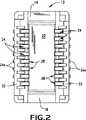
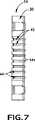
図5〜8を参照すると、レセプタクルコネクタ14は、全体を30で示した絶縁性ハウジングを有し、該絶縁性ハウジングは、プラグコネクタ12と同じように細長くかつ対向端部32を有する。ハウジングは、対向端部32の間に延在し全体を38で示した1対の細長い差込口を画定する中央リブ34と1対の側面リブ36とを備え、この1対の細長い差込口は、後で分かるように、プラグコネクタ12のプラグ部22とプラグ端子28を収容する。 Referring to FIGS. 5-8, the
全体を40で示した複数の第2端子又はレセプタクル端子は、レセプタクルコネクタ14のハウジング30の各側面リブ36に取付けられる。各レセプタクル端子40は、全体を42で示したほぼU字状接触部と、全体を44で示した取付部とを有する。該取付部は、第2回路基板(図示せず)上の適切な回路トレースに接続するためのテール部44aを有する。該テール部44aの下部は、各側面リブ36の底面36a及び中央リブ34の底面34aとほぼ面一である。したがって、レセプタクルコネクタ14は、第2回路基板上に表面実装するように設計されている。各レセプタクル端子40の取付部44は、ハウジング30の各側面リブ36のそれぞれの取付穴46に挿入するための歯付き取付脚部44bを有する。 A plurality of second terminals or receptacle terminals indicated generally at 40 are attached to each
各レセプタクル端子40のほぼU字状接触部42は、レセプタクルコネクタの全長に亘(わた)って延在した差込口38の1つと合致する開放空間を画定するように第2脚部42bから離間された第1脚部42aを有する。U字状接触部42の脚部42aは、柔軟な接触アームを形成し、該柔軟な接触アームの遠位端には内側に向いた接触突起50がある。図9は、第2コネクタ又はレセプタクルコネクタ14と完全に嵌合された第1コネクタ又はプラグコネクタ12を示す。該プラグコネクタは、第1回路基板52に表面実装されて示され、レセプタクルコネクタ14の表面は、第2回路基板54に取付けられている。 The generally U-shaped
図9は、レセプタクルコネクタ内に下方に嵌合されたプラグコネクタを示す。しかしながら、基板対基板コネクタ組立体10はすべての方向で使用し機能することができ、それぞれのコネクタ12及び14のこの向きは、単に例示のためである。その理解の下で、プラグコネクタ12のプラグ部22と凸状接触部24cが、レセプタクル端子40のU字状接触部42によって形成された差込口38に挿入されることが分かる。嵌合する際、柔軟な接触アーム42aの遠位端にある接触突起50が、プラグ端子24の凸状接触部24cの連続弓形接触面28に乗って進むとき、レセプタクル端子の柔軟な接触アーム42aは、矢印「A」で示される方向に内側に付勢される。嵌合プロセスにおいて、接触突起50は、最初、連続弓形接触面の初期表面部28aと最小の係合力で係合する。接触突起50が表面部28bに乗って進むとき、接触突起50が最終ラッチ表面部28cに達するまでに最大の力が生じ、最終ラッチ表面部28cにおいて、コネクタが完全に嵌合した状態で最小の嵌合力が発生する。すべてのレセプタクル端子のすべての接触突起50と、すべてのプラグ端子の最終ラッチ表面部28cの組合された力によって、付加的な挿入力をほとんど、又は、まったく要することなく2つのコネクタの間に良好なラッチが実現される。連続弓形接触面28は、従来技術の押込式ラッチ機構の公差問題による影響を受けない。 FIG. 9 shows the plug connector fitted down into the receptacle connector. However, the board-to-
本発明は、その精神又は中心的特徴から逸脱することなく他の特定の形態で実施できることを理解されよう。したがって、上記の実施例と実施形態は、すべての点において例示的であり限定的でないと考えるべきであり、本発明は、本明細書に示した詳細に限定されない。 It will be understood that the present invention may be embodied in other specific forms without departing from its spirit or central characteristics. Accordingly, the above examples and embodiments are to be considered in all respects as illustrative and not restrictive, and the invention is not limited to the details shown herein.
Claims (3)
Translated fromJapanese第1回路基板(52)上に実装するための絶縁性ハウジング(16)であって、プラグ部(22)を備える絶縁性ハウジングを備える第1コネクタ(12)と、
絶縁性ハウジングに取付けられた複数の第1端子(24)であって、それぞれは、第1回路基板(52)上の適切な回路トレースに接続するテール部(24a)を含み、さらに、絶縁性ハウジング(16)のプラグ部(22)の一側に配設され、連続円弧状接触面(28)を画定する凸状接触部(24c)を含む第1の脚部と、該第1の脚部から離れ、第1コネクタ(12)の絶縁性ハウジング(16)に第1端子(24)を取付けるための取付部を画定するための第2の脚部とを備えるU字形状部を含む複数の第1端子(24)と、
第2回路基板(54)上に実装するための絶縁性ハウジング(30)であって、第2回路基板に隣接する底壁を備える絶縁性ハウジングを備える第2コネクタ(14)と、
第2コネクタの絶縁性ハウジングに取付けられた複数の第2端子(40)であって、それぞれは、取付部とU字状接触部(42)とを含み、前記取付部は、第2回路基板(54)上の適切な回路トレースに接続するテール部(44a)と、ハウジングの側方リブ(36)に挿入する取付脚部(44b)とを備え、前記U字状接触部(42)は、互いに離間する第1及び第2の可撓性接触アームと、結合アームと第2回路基板上の導電性回路との間の電気接続を避けるように形成された絶縁性ハウジングの底壁上に配設され、第1及び第2の可撓性接触アームを接続する結合アームと、第1及び第2コネクタ(12、14)が嵌合されたとき、前記第1端子(24)の凸状接触部(24c)の連続円弧状接触面(28)を摺動して越えるために、第1の可撓性接触アーム(42a)の先端に配設される接触突起部(50)とを備え、第2の可撓性接触アームが取付脚に結合され、前記結合アームと第1及び第2の可撓性接触アームとが第2端子(40)のU字状接触部(42)となり、第1及び第2コネクタ(12、14)の嵌合により、第1端子(24)及びプラグ部(22)がU字状接触部(42)に嵌入するように形成された第2端子(40)とを有し、
各第2端子(40)の接触突起部(50)の対応する第1端子(24)の凸状接触部(24c)との初期の係合が最小の係合力で行われ、この係合力は、接触突起部(50)が摺動して凸状接触部(24c)を越えるのに伴って増加してその後減少し、これにより、両コネクタ(12、14)が嵌合することができるようにするとともに、両回路基板(52、54)が相互に近付くようにし、両コネクタが嵌合した状態で嵌合力が最小となる基板対基板電気コネクタ組立体(10)。A board-to-board electrical connector assembly (10) for making a connection between two circuit boards (52, 54), comprising:
A first connector (12) comprising an insulating housing (16) for mounting on a first circuit board (52), the insulating housing comprising a plug portion (22);
A plurality of first terminals (24) attached to the insulative housing, eachincluding a tail (24a)that connects to a suitable circuit trace on the first circuit board (52), andfurther comprising an insulative A firstleg including a convex contact portion (24c) disposed on one side of the plug portion (22) of the housing (16) and defining a continuous arcuate contact surface (28);and the first leg A plurality of U-shaped portions including asecond leg portion for defining an attachment portion for attaching the first terminal (24) to the insulating housing (16) of the first connector (12) apart from the portion. A first terminal (24) of
A second connector (14) comprising an insulative housing (30) for mounting on a second circuit board (54) comprising an insulative housing comprising a bottom wall adjacent to the second circuit board;
A plurality of second terminals (40) attached to the insulating housing of the second connector, each including an attachment portion and a U-shaped contact portion (42) ,wherein the attachment portion is a second circuit board. (54) with tails (44a) connected to appropriate circuit traces on the top and mounting legs (44b) inserted into the side ribs (36) of the housing, said U-shaped contact (42) being On the bottom wall of the insulative housingformed to avoid electrical connection betweenthe first and second flexible contact arms spaced apart from each other and the conductive circuit on the coupling circuit and the second circuit board; Whenthe coupling arm that is disposedand connects the first and second flexible contact arms andthe first and second connectors (12, 14) are fitted, the convexity of the first terminal (24). To slide over the continuous arcuate contact surface (28) of the contact portion (24c)And a contact protrusion which is arranged at the distal end of thefirst flexible contact arms (42a) (50), coupled tothe second flexible contactarms preparative Tsukeashi,the coupling armand thefirst andasecond flexible contact arm U-shaped contact portion of the second terminal (40) (42), andby the engagement of the first and second connectors (12,14), a first terminal (24) And the plug part (22) hasa second terminal (40)formed so as to fit into the U-shaped contact part (42),
The initial engagement of the contact protrusion (50) of each second terminal (40) with the corresponding convex contact (24c) of the first terminal (24 ) is performed with a minimum engagement force. As the contact protrusion (50) slides and exceeds the convex contact portion (24c), it increases and then decreases, so that both connectors (12, 14) can be fitted together. as well as in both circuits as the substrate (52, 54) approaches one another, the connectors comprising fitting force with minimum is fitted state board-to-board electrical connectorassembly (10).
Applications Claiming Priority (2)
| Application Number | Priority Date | Filing Date | Title |
|---|---|---|---|
| US10/661,686US6811411B1 (en) | 2003-09-12 | 2003-09-12 | Board-to-board electrical connector assembly |
| PCT/US2004/028443WO2005034296A1 (en) | 2003-09-12 | 2004-09-01 | Board to-board electrical connector assembly |
Publications (2)
| Publication Number | Publication Date |
|---|---|
| JP2007505471A JP2007505471A (en) | 2007-03-08 |
| JP4308259B2true JP4308259B2 (en) | 2009-08-05 |
Family
ID=33300271
Family Applications (1)
| Application Number | Title | Priority Date | Filing Date |
|---|---|---|---|
| JP2006526167AExpired - Fee RelatedJP4308259B2 (en) | 2003-09-12 | 2004-09-01 | Board-to-board electrical connector assembly |
Country Status (5)
| Country | Link |
|---|---|
| US (2) | US6811411B1 (en) |
| JP (1) | JP4308259B2 (en) |
| CN (1) | CN100533862C (en) |
| TW (1) | TWI279035B (en) |
| WO (1) | WO2005034296A1 (en) |
Families Citing this family (40)
| Publication number | Priority date | Publication date | Assignee | Title |
|---|---|---|---|---|
| US7628617B2 (en) | 2003-06-11 | 2009-12-08 | Neoconix, Inc. | Structure and process for a contact grid array formed in a circuitized substrate |
| US8584353B2 (en) | 2003-04-11 | 2013-11-19 | Neoconix, Inc. | Method for fabricating a contact grid array |
| US7244125B2 (en) | 2003-12-08 | 2007-07-17 | Neoconix, Inc. | Connector for making electrical contact at semiconductor scales |
| US7758351B2 (en) | 2003-04-11 | 2010-07-20 | Neoconix, Inc. | Method and system for batch manufacturing of spring elements |
| US20070020960A1 (en) | 2003-04-11 | 2007-01-25 | Williams John D | Contact grid array system |
| US7597561B2 (en) | 2003-04-11 | 2009-10-06 | Neoconix, Inc. | Method and system for batch forming spring elements in three dimensions |
| US7114961B2 (en) | 2003-04-11 | 2006-10-03 | Neoconix, Inc. | Electrical connector on a flexible carrier |
| US7347698B2 (en) | 2004-03-19 | 2008-03-25 | Neoconix, Inc. | Deep drawn electrical contacts and method for making |
| WO2005091998A2 (en) | 2004-03-19 | 2005-10-06 | Neoconix, Inc. | Electrical connector in a flexible host |
| JP2005294034A (en)* | 2004-03-31 | 2005-10-20 | Matsushita Electric Works Ltd | Connector |
| US7354276B2 (en) | 2004-07-20 | 2008-04-08 | Neoconix, Inc. | Interposer with compliant pins |
| US7144277B2 (en)* | 2004-09-09 | 2006-12-05 | Hon Hai Precision Ind. Co., Ltd. | Electrical connector with guidance face |
| JP2006164594A (en)* | 2004-12-03 | 2006-06-22 | Molex Inc | Substrate-to-substrate connector |
| TW200633315A (en)* | 2005-03-01 | 2006-09-16 | Top Yang Technology Entpr Co | Electrical connector |
| JP4592462B2 (en)* | 2005-03-23 | 2010-12-01 | モレックス インコーポレイテド | Board connector |
| JP4526428B2 (en)* | 2005-04-18 | 2010-08-18 | モレックス インコーポレイテド | Board to board connector |
| US7357644B2 (en) | 2005-12-12 | 2008-04-15 | Neoconix, Inc. | Connector having staggered contact architecture for enhanced working range |
| TWI305691B (en)* | 2006-01-20 | 2009-01-21 | Hon Hai Prec Ind Co Ltd | Electrical connector assembly |
| US7150652B1 (en) | 2006-02-21 | 2006-12-19 | Myoungsoo Jeon | Connector having a pair of printed circuits and facing sets of contact beams |
| TWM300882U (en)* | 2006-05-26 | 2006-11-11 | Advanced Connectek Inc | Electric connector assembly |
| JP2007328961A (en)* | 2006-06-06 | 2007-12-20 | Kyocera Elco Corp | Connector device |
| CN200959412Y (en)* | 2006-08-18 | 2007-10-10 | 富士康(昆山)电脑接插件有限公司 | electrical connector |
| US7402054B2 (en)* | 2006-11-27 | 2008-07-22 | Cheng Uei Precision Industry Co., Ltd. | Board-to-board connector |
| US7597573B2 (en)* | 2007-02-26 | 2009-10-06 | Tyco Electronics Corporation | Low profile high current power connector with cooling slots |
| DE102007031621B4 (en)* | 2007-07-06 | 2009-12-10 | Amphenol-Tuchel Electronics Gmbh | Terminal block with hermaphroditic contacts |
| US8287289B2 (en)* | 2008-06-10 | 2012-10-16 | Molex Incorporated | Elastic-cushioned capacitively-coupled connector |
| US7677903B1 (en)* | 2008-11-28 | 2010-03-16 | Cheng Uei Precision Industry Co., Ltd. | Board-to-board connector assembly |
| JP5113101B2 (en) | 2009-01-30 | 2013-01-09 | モレックス インコーポレイテド | Electrical circuit connection structure and electrical circuit connection method |
| CN202094345U (en)* | 2010-05-24 | 2011-12-28 | 蔡闳宇 | electrical connector |
| US20130023162A1 (en)* | 2011-07-20 | 2013-01-24 | Hon Hai Precision Industry Co., Ltd. | Low profile electrical connector having improved terminals |
| TWI504076B (en)* | 2011-09-30 | 2015-10-11 | Assem Technology Co Ltd | Electrical connector and assembly thereof |
| US8888506B2 (en)* | 2013-01-29 | 2014-11-18 | Japan Aviation Electronics Industry, Limited | Connector |
| CN104137344B (en)* | 2013-02-27 | 2017-06-30 | 松下知识产权经营株式会社 | Connector, and plug and socket used in the connector |
| US9680273B2 (en) | 2013-03-15 | 2017-06-13 | Neoconix, Inc | Electrical connector with electrical contacts protected by a layer of compressible material and method of making it |
| JP6537890B2 (en)* | 2014-09-26 | 2019-07-03 | 日本航空電子工業株式会社 | connector |
| CN105470674B (en)* | 2016-01-11 | 2020-10-23 | 深圳前海达闼云端智能科技有限公司 | High-power equipment connector |
| US9831579B1 (en)* | 2016-08-01 | 2017-11-28 | Motorola Solutions, Inc. | Adapter frame with a set of electrical pads on its top and bottom surfaces for a board-to-board connection |
| CN109496377B (en)* | 2016-08-04 | 2020-10-30 | 京瓷株式会社 | contact |
| JP6959802B2 (en)* | 2017-09-04 | 2021-11-05 | 日本航空電子工業株式会社 | connector |
| CN110061375B (en)* | 2018-01-19 | 2020-11-13 | 莫列斯有限公司 | Connector, butting connector and connector assembly |
Family Cites Families (18)
| Publication number | Priority date | Publication date | Assignee | Title |
|---|---|---|---|---|
| EP0450770B1 (en) | 1990-04-02 | 1995-11-22 | The Whitaker Corporation | Surface mount connector |
| US5181855A (en) | 1991-10-03 | 1993-01-26 | Itt Corporation | Simplified contact connector system |
| US5310357A (en) | 1993-02-22 | 1994-05-10 | Berg Technology, Inc. | Blade-like terminal having a passive latch |
| JP2848762B2 (en) | 1993-07-26 | 1999-01-20 | 三菱電機株式会社 | Data transfer system and method |
| JP2598650Y2 (en)* | 1993-12-14 | 1999-08-16 | モレックス インコーポレーテッド | Electrical connector for connecting printed circuit boards |
| US5395250A (en) | 1994-01-21 | 1995-03-07 | The Whitaker Corporation | Low profile board to board connector |
| EP0693796A1 (en) | 1994-07-22 | 1996-01-24 | Connector Systems Technology N.V. | Connector provided with metal strips as contact members, connector assembly comprising such a connector |
| JP3194215B2 (en) | 1996-03-14 | 2001-07-30 | モレックス インコーポレーテッド | Electrical connector assembly and method of adjusting its mating holding force |
| US5876217A (en)* | 1996-03-14 | 1999-03-02 | Molex Incorporated | Electric connector assembly with improved retention characteristics |
| JP3617220B2 (en) | 1996-11-26 | 2005-02-02 | 松下電工株式会社 | connector |
| US5971809A (en) | 1997-07-30 | 1999-10-26 | Hon Hai Precision Ind. Co., Ltd. | Electrical connector assembly |
| JPH1174024A (en) | 1997-08-29 | 1999-03-16 | Omron Corp | Electric connector |
| JP2000260509A (en) | 1999-03-10 | 2000-09-22 | Jst Mfg Co Ltd | Board-to-board connector system |
| JP3368471B2 (en) | 1999-10-25 | 2003-01-20 | 日本航空電子工業株式会社 | Electrical connector |
| US6338630B1 (en) | 2000-07-28 | 2002-01-15 | Hon Hai Precision Ind. Co., Ltd. | Board-to-board connector with improved contacts |
| JP3682649B2 (en) | 2001-11-27 | 2005-08-10 | 日本航空電子工業株式会社 | Connector device |
| JP4441157B2 (en) | 2002-01-28 | 2010-03-31 | パナソニック電工株式会社 | connector |
| JP4133464B2 (en) | 2003-03-07 | 2008-08-13 | 日本圧着端子製造株式会社 | Board electrical connector |
- 2003
- 2003-09-12USUS10/661,686patent/US6811411B1/ennot_activeCeased
- 2004
- 2004-09-01JPJP2006526167Apatent/JP4308259B2/ennot_activeExpired - Fee Related
- 2004-09-01WOPCT/US2004/028443patent/WO2005034296A1/enactiveApplication Filing
- 2004-09-01CNCNB2004800259171Apatent/CN100533862C/ennot_activeExpired - Fee Related
- 2004-09-10TWTW093127431Apatent/TWI279035B/ennot_activeIP Right Cessation
- 2006
- 2006-11-02USUS11/592,314patent/USRE41473E1/ennot_activeExpired - Fee Related
Also Published As
| Publication number | Publication date |
|---|---|
| TW200531360A (en) | 2005-09-16 |
| US6811411B1 (en) | 2004-11-02 |
| TWI279035B (en) | 2007-04-11 |
| WO2005034296A1 (en) | 2005-04-14 |
| CN1849727A (en) | 2006-10-18 |
| USRE41473E1 (en) | 2010-08-03 |
| CN100533862C (en) | 2009-08-26 |
| JP2007505471A (en) | 2007-03-08 |
Similar Documents
| Publication | Publication Date | Title |
|---|---|---|
| JP4308259B2 (en) | Board-to-board electrical connector assembly | |
| CN101133522B (en) | Board Mount Electrical Connectors | |
| US6183287B1 (en) | Electrical connector | |
| CN100541939C (en) | Socket and Plug Connectors | |
| JP2887579B2 (en) | Locking electrical connector and method of manufacturing the same | |
| US5161985A (en) | Board to board interconnect | |
| JP5250450B2 (en) | Electrical connector | |
| US6776646B2 (en) | Electrical connector assembly having locking member | |
| US5224866A (en) | Surface mount connector | |
| US7422465B2 (en) | Electrical connector having flexible mating portion | |
| KR100231122B1 (en) | Electrical connector with improved terminal positioning means | |
| JP2009218221A (en) | Board-to-board electrical connector assembly | |
| JP4851510B2 (en) | Electrical connector | |
| JP2006302901A (en) | Substrate-to-substrate connector equipped with improved terminal contact | |
| US20020142629A1 (en) | Board mounted electrical connector assembly | |
| KR20140125884A (en) | Substrate connector | |
| JP7214837B2 (en) | header connector | |
| JP2014191882A (en) | Electric connector | |
| JP3898643B2 (en) | Small board to board connector | |
| US6074230A (en) | Hermaphroditic electrical connectors | |
| US6186833B1 (en) | Hybrid connector with audio jack | |
| US6805571B2 (en) | Electrical connector assembly having locking device | |
| JP2001357944A (en) | Plug connector | |
| US6146172A (en) | Electrical connector | |
| JP2000277199A (en) | Terminal structure of electric connector |
Legal Events
| Date | Code | Title | Description |
|---|---|---|---|
| A131 | Notification of reasons for refusal | Free format text:JAPANESE INTERMEDIATE CODE: A131 Effective date:20080916 | |
| A601 | Written request for extension of time | Free format text:JAPANESE INTERMEDIATE CODE: A601 Effective date:20081215 | |
| A602 | Written permission of extension of time | Free format text:JAPANESE INTERMEDIATE CODE: A602 Effective date:20081222 | |
| A601 | Written request for extension of time | Free format text:JAPANESE INTERMEDIATE CODE: A601 Effective date:20090115 | |
| A602 | Written permission of extension of time | Free format text:JAPANESE INTERMEDIATE CODE: A602 Effective date:20090122 | |
| A521 | Request for written amendment filed | Free format text:JAPANESE INTERMEDIATE CODE: A523 Effective date:20090203 | |
| TRDD | Decision of grant or rejection written | ||
| A01 | Written decision to grant a patent or to grant a registration (utility model) | Free format text:JAPANESE INTERMEDIATE CODE: A01 Effective date:20090421 | |
| A01 | Written decision to grant a patent or to grant a registration (utility model) | Free format text:JAPANESE INTERMEDIATE CODE: A01 | |
| A61 | First payment of annual fees (during grant procedure) | Free format text:JAPANESE INTERMEDIATE CODE: A61 Effective date:20090430 | |
| R150 | Certificate of patent or registration of utility model | Ref document number:4308259 Country of ref document:JP Free format text:JAPANESE INTERMEDIATE CODE: R150 Free format text:JAPANESE INTERMEDIATE CODE: R150 | |
| FPAY | Renewal fee payment (event date is renewal date of database) | Free format text:PAYMENT UNTIL: 20120515 Year of fee payment:3 | |
| FPAY | Renewal fee payment (event date is renewal date of database) | Free format text:PAYMENT UNTIL: 20120515 Year of fee payment:3 | |
| FPAY | Renewal fee payment (event date is renewal date of database) | Free format text:PAYMENT UNTIL: 20130515 Year of fee payment:4 | |
| R250 | Receipt of annual fees | Free format text:JAPANESE INTERMEDIATE CODE: R250 | |
| FPAY | Renewal fee payment (event date is renewal date of database) | Free format text:PAYMENT UNTIL: 20140515 Year of fee payment:5 | |
| R250 | Receipt of annual fees | Free format text:JAPANESE INTERMEDIATE CODE: R250 | |
| R250 | Receipt of annual fees | Free format text:JAPANESE INTERMEDIATE CODE: R250 | |
| R250 | Receipt of annual fees | Free format text:JAPANESE INTERMEDIATE CODE: R250 | |
| S533 | Written request for registration of change of name | Free format text:JAPANESE INTERMEDIATE CODE: R313533 | |
| R350 | Written notification of registration of transfer | Free format text:JAPANESE INTERMEDIATE CODE: R350 | |
| R250 | Receipt of annual fees | Free format text:JAPANESE INTERMEDIATE CODE: R250 | |
| R250 | Receipt of annual fees | Free format text:JAPANESE INTERMEDIATE CODE: R250 | |
| R250 | Receipt of annual fees | Free format text:JAPANESE INTERMEDIATE CODE: R250 | |
| R250 | Receipt of annual fees | Free format text:JAPANESE INTERMEDIATE CODE: R250 | |
| LAPS | Cancellation because of no payment of annual fees |