JP4306752B2 - Imaging device, photometry method, luminance calculation method, program - Google Patents
Imaging device, photometry method, luminance calculation method, programDownload PDFInfo
- Publication number
- JP4306752B2 JP4306752B2JP2007070443AJP2007070443AJP4306752B2JP 4306752 B2JP4306752 B2JP 4306752B2JP 2007070443 AJP2007070443 AJP 2007070443AJP 2007070443 AJP2007070443 AJP 2007070443AJP 4306752 B2JP4306752 B2JP 4306752B2
- Authority
- JP
- Japan
- Prior art keywords
- imaging
- processing
- exposure
- unit
- imaging mode
- Prior art date
- Legal status (The legal status is an assumption and is not a legal conclusion. Google has not performed a legal analysis and makes no representation as to the accuracy of the status listed.)
- Expired - Fee Related
Links
- 238000003384imaging methodMethods0.000titleclaimsdescription266
- 238000000034methodMethods0.000titleclaimsdescription147
- 238000005375photometryMethods0.000titleclaimsdescription85
- 238000004364calculation methodMethods0.000titleclaimsdescription9
- 238000001514detection methodMethods0.000claimsdescription128
- 238000012545processingMethods0.000claimsdescription126
- 239000002131composite materialSubstances0.000claimsdescription73
- 230000005856abnormalityEffects0.000claimsdescription40
- 238000011156evaluationMethods0.000claimsdescription20
- 238000003672processing methodMethods0.000claimsdescription16
- 230000015572biosynthetic processEffects0.000claimsdescription8
- 238000003786synthesis reactionMethods0.000claimsdescription8
- 238000012935AveragingMethods0.000claims2
- 241000287463PhalacrocoraxSpecies0.000claims1
- 230000008569processEffects0.000description35
- 230000003287optical effectEffects0.000description17
- 238000007781pre-processingMethods0.000description16
- 238000012937correctionMethods0.000description4
- 230000033001locomotionEffects0.000description4
- 230000008859changeEffects0.000description3
- 230000000875corresponding effectEffects0.000description3
- 230000000694effectsEffects0.000description3
- 101000911772Homo sapiens Hsc70-interacting proteinProteins0.000description2
- 101001139126Homo sapiens Krueppel-like factor 6Proteins0.000description2
- 238000010586diagramMethods0.000description2
- 230000006870functionEffects0.000description2
- 238000010191image analysisMethods0.000description2
- 230000010354integrationEffects0.000description2
- 230000004044responseEffects0.000description2
- 239000004065semiconductorSubstances0.000description2
- 230000002194synthesizing effectEffects0.000description2
- 238000012546transferMethods0.000description2
- 101000661807Homo sapiens Suppressor of tumorigenicity 14 proteinProteins0.000description1
- 230000002159abnormal effectEffects0.000description1
- 230000005540biological transmissionEffects0.000description1
- 238000006243chemical reactionMethods0.000description1
- 230000000295complement effectEffects0.000description1
- 238000007796conventional methodMethods0.000description1
- 230000002596correlated effectEffects0.000description1
- 230000002542deteriorative effectEffects0.000description1
- 230000006872improvementEffects0.000description1
- 239000004973liquid crystal related substanceSubstances0.000description1
- 229910044991metal oxideInorganic materials0.000description1
- 150000004706metal oxidesChemical class0.000description1
- 239000000203mixtureSubstances0.000description1
- 238000012544monitoring processMethods0.000description1
- 230000007935neutral effectEffects0.000description1
- 230000002093peripheral effectEffects0.000description1
- 238000005070samplingMethods0.000description1
- 229920006395saturated elastomerPolymers0.000description1
- 230000035945sensitivityEffects0.000description1
- 239000007787solidSubstances0.000description1
- 230000002087whitening effectEffects0.000description1
Images


Classifications
- G—PHYSICS
- G03—PHOTOGRAPHY; CINEMATOGRAPHY; ANALOGOUS TECHNIQUES USING WAVES OTHER THAN OPTICAL WAVES; ELECTROGRAPHY; HOLOGRAPHY
- G03B—APPARATUS OR ARRANGEMENTS FOR TAKING PHOTOGRAPHS OR FOR PROJECTING OR VIEWING THEM; APPARATUS OR ARRANGEMENTS EMPLOYING ANALOGOUS TECHNIQUES USING WAVES OTHER THAN OPTICAL WAVES; ACCESSORIES THEREFOR
- G03B7/00—Control of exposure by setting shutters, diaphragms or filters, separately or conjointly
- G03B7/08—Control effected solely on the basis of the response, to the intensity of the light received by the camera, of a built-in light-sensitive device
- G03B7/091—Digital circuits
- G03B7/093—Digital circuits for control of exposure time
- G—PHYSICS
- G09—EDUCATION; CRYPTOGRAPHY; DISPLAY; ADVERTISING; SEALS
- G09G—ARRANGEMENTS OR CIRCUITS FOR CONTROL OF INDICATING DEVICES USING STATIC MEANS TO PRESENT VARIABLE INFORMATION
- G09G3/00—Control arrangements or circuits, of interest only in connection with visual indicators other than cathode-ray tubes
- G09G3/20—Control arrangements or circuits, of interest only in connection with visual indicators other than cathode-ray tubes for presentation of an assembly of a number of characters, e.g. a page, by composing the assembly by combination of individual elements arranged in a matrix no fixed position being assigned to or needed to be assigned to the individual characters or partial characters
- G09G3/34—Control arrangements or circuits, of interest only in connection with visual indicators other than cathode-ray tubes for presentation of an assembly of a number of characters, e.g. a page, by composing the assembly by combination of individual elements arranged in a matrix no fixed position being assigned to or needed to be assigned to the individual characters or partial characters by control of light from an independent source
- G09G3/36—Control arrangements or circuits, of interest only in connection with visual indicators other than cathode-ray tubes for presentation of an assembly of a number of characters, e.g. a page, by composing the assembly by combination of individual elements arranged in a matrix no fixed position being assigned to or needed to be assigned to the individual characters or partial characters by control of light from an independent source using liquid crystals
- G09G3/3611—Control of matrices with row and column drivers
- H—ELECTRICITY
- H04—ELECTRIC COMMUNICATION TECHNIQUE
- H04N—PICTORIAL COMMUNICATION, e.g. TELEVISION
- H04N23/00—Cameras or camera modules comprising electronic image sensors; Control thereof
- H04N23/70—Circuitry for compensating brightness variation in the scene
- H04N23/73—Circuitry for compensating brightness variation in the scene by influencing the exposure time
- H—ELECTRICITY
- H04—ELECTRIC COMMUNICATION TECHNIQUE
- H04N—PICTORIAL COMMUNICATION, e.g. TELEVISION
- H04N23/00—Cameras or camera modules comprising electronic image sensors; Control thereof
- H04N23/70—Circuitry for compensating brightness variation in the scene
- H04N23/741—Circuitry for compensating brightness variation in the scene by increasing the dynamic range of the image compared to the dynamic range of the electronic image sensors
Landscapes
- Engineering & Computer Science (AREA)
- Multimedia (AREA)
- Signal Processing (AREA)
- Physics & Mathematics (AREA)
- General Physics & Mathematics (AREA)
- Chemical & Material Sciences (AREA)
- Crystallography & Structural Chemistry (AREA)
- Computer Hardware Design (AREA)
- Theoretical Computer Science (AREA)
- Studio Devices (AREA)
- Exposure Control For Cameras (AREA)
Description
Translated fromJapanese本発明は撮像装置、測光方法、輝度算出方法、プログラムに関し、特に撮像動作として通常撮像モードと合成撮像モードを切り換えて実行できる撮像装置に関する。 The present invention relates to an imaging apparatus, a photometric method, a luminance calculation method, and a program, and more particularly to an imaging apparatus that can be executed by switching between a normal imaging mode and a composite imaging mode as an imaging operation.
従来のCCD(Charge Coupled Device)等の固体撮像素子を用いた撮像装置では、撮像素子に入力される光量(露光量)を、絞りや電子シャッタースピードによって調節している。つまり、明るいシーンを撮影するときには撮像素子の出力信号が飽和していわゆる白つぶれ(露出過多:overexposure)が発生しないように露光量を少なくし、逆に暗いシーンではいわゆる黒つぶれ(露出不足:underexposure)が発生しないように露光量を多くするように、露光量を調節している。 In an imaging apparatus using a solid-state imaging device such as a conventional CCD (Charge Coupled Device), the amount of light (exposure amount) input to the imaging device is adjusted by an aperture or an electronic shutter speed. In other words, when shooting a bright scene, the exposure signal is reduced so that the output signal of the image sensor is not saturated and so-called whitening (overexposure) does not occur. The exposure amount is adjusted so that the exposure amount is increased so as not to occur.
しかしながら、明暗の差が大きいシーンの撮影(逆光撮影、屋内外同時撮影)する場合、使用する固体撮像素子のダイナミックレンジ不足により、露光量の調節だけでは、明るい部分が飽和していわゆる白とびが発生してしまったり、暗い部分で黒つぶれが発生してしまい、両方の部分を適正に再現できないという問題がある。 However, when shooting a scene with a large contrast between light and dark (backlight shooting, indoor / outdoor simultaneous shooting), the dynamic range of the solid-state image sensor used is insufficient. There is a problem that it occurs or a black part is generated in a dark part, and both parts cannot be reproduced properly.
この問題を解決するために、フィールド内で二つの異なる電子シャッタスピードを使用したり、フィールド毎に電子シャッタスピードを変えて、明るいエリアの情報と暗いエリアの情報とを別々に撮像し、得られたそれぞれの情報を1枚の画像に合成する方法が既に開発されている(上記特許文献1参照)。
これを応用したものとして、ダイナミックレンジの広い画像を撮像可能な装置(ワイドダイナミックレンジカメラ)があり、その合成画像の品質を向上させる装置・方法が上記特許文献2,3に開示されている。In order to solve this problem, it is possible to use two different electronic shutter speeds in the field or change the electronic shutter speed for each field to capture information on bright areas and information on dark areas separately. In addition, a method for combining each piece of information into one image has already been developed (see Patent Document 1).
As an application of this, there is an apparatus (wide dynamic range camera) capable of capturing an image with a wide dynamic range, and apparatuses and methods for improving the quality of the composite image are disclosed in
しかしながら、上記特許文献2,3等の従来の技術にあっては、2種類の異なる露光量で撮像された画像を合成する方法を改善することによりワイドダイナミックレンジカメラの画質の向上を目指しているが、露光制御のための測光方式という観点での改善手法は述べられていない。 However, the conventional techniques such as
一般的にワイドダイナミックレンジカメラは動作状態として、ワイドダイナミックレンジ撮像を行う合成撮影モードと、ワイドダイナミックレンジ撮像を行わない通常撮像モードの2種類を持つ。
通常撮像モードで自動的に設定される(カメラ利用者の操作を伴わない)測光方式としては、中央部重点測光方式、或いは評価測光方式が一般的に採用されている。
中央部重点測光方式は、画像の中央付近を重点的に測光する方式で、画像中心部に主要被写体があることを前提としている。例えば上記特許文献4にも示されている。
また評価測光方式(分割測光方式、マルチパターン測光方式などとも呼ばれる)は、画像を複数に分割して測光し、これら複数の情報から過順光や逆光条件などを判断し、適正な露光を行う。さらに合焦位置を加味する、分割数をより多くするなどといった手法があり、特性を一意に決めることはできない。この評価測光方式のアルゴリズムは、カメラ製造メーカ各社により、様々なものが採用されている。In general, a wide dynamic range camera has two types of operating states: a composite shooting mode in which wide dynamic range imaging is performed and a normal imaging mode in which wide dynamic range imaging is not performed.
As the metering method automatically set in the normal imaging mode (without camera user operation), the center-weighted metering method or the evaluation metering method is generally employed.
The center-weighted metering method is a method that focuses light on the vicinity of the center of the image, and assumes that the main subject is in the center of the image. For example, it is shown also in the said patent document 4. FIG.
The evaluation metering method (also called division metering method, multi-pattern metering method, etc.) measures images by dividing an image into a plurality of pieces of information, and judges appropriate conditions such as over-order light and backlight conditions from these pieces of information. . In addition, there are methods such as adding the in-focus position and increasing the number of divisions, and the characteristics cannot be determined uniquely. Various algorithms of this evaluation photometry method are adopted by camera manufacturers.
しかしながらこれらの二つの測光方式はダイナミックレンジの狭い通常撮像モードにおいて、特定の部分に重み付けを行うことで、主要被写体に対して適切な露光を行うことを目的としたものである。これに対してダイナミックレンジを拡大させた合成撮像モードでは、撮像画像のエリア全体を認識(目視)できるようすることが目的であることから、上記の測光方式は最適な測光方式とは言えない。
そこで本発明は、通常撮像モードと合成撮像モードを切り換えて撮像を行うことのできる撮像装置において、適切な測光が行われるようにすることを目的とする。However, these two photometric methods are intended to perform appropriate exposure on the main subject by weighting specific portions in the normal imaging mode with a narrow dynamic range. On the other hand, in the composite imaging mode in which the dynamic range is expanded, the purpose is to be able to recognize (view) the entire area of the captured image, and thus the above-mentioned photometric method is not an optimal photometric method.
Therefore, an object of the present invention is to perform appropriate photometry in an imaging apparatus that can perform imaging by switching between a normal imaging mode and a composite imaging mode.
本発明の撮像装置は、1つの露光画像信号について信号処理を行って撮像画像データを生成する通常撮像モードの撮像動作と、露光時間が相対的に長い長時間露光画像信号と露光時間が相対的に短い短時間露光画像信号を得、上記長時間露光画像信号と上記短時間露光画像信号の合成処理を含む信号処理を行って撮像画像データを生成する合成撮像モードの撮像動作とが選択的に実行可能な撮像処理部と、上記撮像処理部で生成された撮像画像データについて測光処理を行う検波部と、上記通常撮像モードか上記合成撮像モードかに応じて、上記検波部の測光処理方式の切換制御を行う制御部とを備える。
また上記制御部は、上記検波部の測光処理の結果に基づいて上記撮像処理部の露光制御を行う。
また上記制御部は、上記通常撮像モードでの撮像動作の際には、上記検波部の測光処理方式を中央部重点測光方式又は評価測光方式に制御する。
また上記制御部は、上記合成撮像モードでの撮像動作の際には、上記検波部の測光処理方式を平均測光方式に制御する。
また上記制御部は、上記通常撮像モード又は上記合成撮像モードでの撮像動作の際に、指定入力に応じて、上記検波部の測光処理方式を部分測光方式に制御する。
また上記撮像処理部で得られた撮像画像データから被写体の異常を検知する異常検知部をさらに備え、上記制御部は、上記通常撮像モード又は上記合成撮像モードでの撮像動作の際に、上記異常検知部により異常が検知された場合は、上記検波部の測光処理方式を部分測光方式に制御する。
The imaging apparatus according to the present invention includes an imaging operation in a normal imaging mode in which signal processing is performed onone exposure image signal to generate captured image data, a long exposure image signal with a relatively long exposure time, and a relative exposure time. Imaging operation in a composite imaging mode in which a short-time exposure image signal is obtained and signal processing including synthesis processing of the long-time exposure image signal and the short-time exposure image signal is performed to generate captured image data. Depending on whether the imaging processing unit is executable, the detection unit that performs photometry processing on the captured image data generated by the imaging processing unit, and the normal imaging mode or the composite imaging mode, the photometric processing method of the detection unit And a control unit that performs switching control.
Further, the control unit performs exposure control of the imaging processing unit based on a result of photometry processing of the detection unit.
Further, the control unit controls the photometric processing method of the detection unit to the center-weighted photometric method or the evaluation photometric method in the imaging operation in the normal imaging mode.
Further, the control unit controls the photometric processing method of the detection unit to the average photometric method in the imaging operation in the composite imaging mode.
The control unit controls the photometry processing method of the detection unit to the partial photometry method in accordance with the designated input during the imaging operation in the normal imaging mode or the composite imaging mode.
The image processing apparatus further includes an abnormality detection unit that detects an abnormality of the subject from the captured image data obtained by the imaging processing unit, and the control unit performs the abnormality in the imaging operation in the normal imaging mode or the composite imaging mode. When an abnormality is detected by the detection unit, the photometry processing method of the detection unit is controlled to the partial photometry method.
本発明の測光方法は、通常撮像モードの撮像動作と合成撮像モードの撮像動作とが選択的に実行可能な撮像装置の測光方法であり、上記通常撮像モードで撮像動作を行う際には、上記撮像処理部で生成された撮像画像データについて中央部重点測光方式又は評価測光方式により測光処理を行い、上記合成撮像モードで撮像動作を行う際には、上記撮像処理部で生成された撮像画像データについて平均測光方式により測光処理を行う。 The photometric method of the present invention is a photometric method of an imaging apparatus capable of selectively performing an imaging operation in a normal imaging mode and an imaging operation in a composite imaging mode. When performing an imaging operation in the normal imaging mode, When the imaged image data generated by the imaging processing unit is subjected to photometric processing by the center-weighted metering method or the evaluation metering method, and the imaging operation is performed in the composite imaging mode, the captured image data generated by the imaging processing unit Photometric processing is performed using the average photometry method.
本発明の輝度算出方法は、通常撮像モードの撮像動作と合成撮像モードの撮像動作とが選択的に実行可能な撮像処理部と、上記撮像処理部で生成された撮像画像データについて測光処理を行う検波部とを備えた撮像装置における撮像画像データの輝度算出方法であり、上記通常撮像モードか上記合成撮像モードかに応じて上記検波部の測光処理方式の切換制御を行うステップと、上記検波部の測光処理により得られた値、例えば輝度積算値を入力し、入力した値に対して、上記検波部で実行された測光処理方式に応じた演算を行って単位面積当たりの輝度値を算出するステップとを備える。
また本発明のプログラムは、上記輝度算出方法としての各ステップを演算処理装置に実行させるプログラムである。The luminance calculation method of the present invention performs a photometric process on an imaging processing unit capable of selectively executing an imaging operation in a normal imaging mode and an imaging operation in a composite imaging mode, and captured image data generated by the imaging processing unit. A luminance calculation method of captured image data in an imaging apparatus including a detection unit, the step of performing a switching control of a photometric processing method of the detection unit according to the normal imaging mode or the composite imaging mode, and the detection unit The value obtained by the photometric processing, for example, the luminance integrated value is input, and the luminance value per unit area is calculated by performing an operation according to the photometric processing method executed by the detector on the input value. Steps.
Moreover, the program of this invention is a program which makes an arithmetic processing unit perform each step as the said brightness | luminance calculation method.
以上の本発明では、通常撮像モードの撮像動作と合成撮像モードの撮像動作とが選択的に実行可能な撮像装置において、その撮像モードに応じて測光方式が切り換えられることになる。
例えば通常撮像モードでは中央部重点測光方式、又は評価測光方式を実行する。一方、ダイナミックレンジを拡大させた合成撮像モードは、撮像画像のエリア全体を認識(目視)できるようすることが目的であることから、主要被写体を重点をおいて測光する測光方式は最適ではないため、例えば合成撮像モードの際には平均測光(全面測光とも言う)を適用する。平均測光(全面測光)とは、撮像画像の全体で測光を行い、その平均値を輝度として扱う方式である。In the present invention described above, in the imaging apparatus capable of selectively executing the imaging operation in the normal imaging mode and the imaging operation in the composite imaging mode, the photometry method is switched according to the imaging mode.
For example, in the normal imaging mode, the center-weighted metering method or the evaluation metering method is executed. On the other hand, the composite imaging mode with an expanded dynamic range is intended to make it possible to recognize (view) the entire area of the captured image, so the metering method that focuses on the main subject is not optimal. For example, average photometry (also referred to as full surface photometry) is applied in the composite imaging mode. Average photometry (entire photometry) is a method in which photometry is performed on the entire captured image and the average value is treated as luminance.
本発明によれば、通常撮像モードと、ワイドダイナミックレンジを得るための合成撮像モードとの各場合において測光方式を切り替えることで、通常撮像モード、合成撮像モードのそれぞれに適した測光を行うことができる。そしてそのような適切な測光に基づいて露光制御を行うことで、ダイナミックレンジの狭い通常撮影モードの画質を損なうことなく、合成撮像モードでの自動露光の性能を向上させることも可能となる。 According to the present invention, metering suitable for each of the normal imaging mode and the composite imaging mode can be performed by switching the photometry method in each case of the normal imaging mode and the composite imaging mode for obtaining a wide dynamic range. it can. By performing exposure control based on such appropriate photometry, it is possible to improve the performance of automatic exposure in the composite imaging mode without deteriorating the image quality in the normal imaging mode with a narrow dynamic range.
以下、本発明の実施の形態を次の順序で説明する。
[1.通常撮像モードと合成撮像モード]
[2.撮像装置の構成]
[3.撮像装置の全体動作]
[4.制御部の処理例I]
[5.制御部の処理例II]
[6.制御部の処理例III]
[7.実施の形態の効果、及びプログラム]
Hereinafter, embodiments of the present invention will be described in the following order.
[1. Normal imaging mode and composite imaging mode]
[2. Configuration of imaging device]
[3. Overall operation of imaging device]
[4. Control unit processing example I]
[5. Control unit processing example II]
[6. Control unit processing example III]
[7. Effects of Embodiment and Program]
[1.通常撮像モードと合成撮像モード]
本実施の形態の撮像装置1は、ワイドダイナミックレンジカメラとしての合成撮像モードの撮像動作が可能な撮像装置であり、例えば監視カメラなどとして好適に用いられる。もちろん一般ユーザが通常用いるデジタルスチルカメラ、デジタルビデオカメラなどとしても適用可能である。
ここではまず、通常撮像モードと合成撮像モードについて述べておく。[1. Normal imaging mode and composite imaging mode]
The imaging apparatus 1 according to the present embodiment is an imaging apparatus capable of performing an imaging operation in a composite imaging mode as a wide dynamic range camera, and is preferably used as a surveillance camera, for example. Of course, the present invention can also be applied to a digital still camera, a digital video camera and the like that are normally used by general users.
First, the normal imaging mode and the composite imaging mode will be described.
一般的に使用される撮像装置における通常の撮像動作(通常撮像モード)では、被写体における非常に暗い部分と非常に明るい部分までの広範囲にわたるダイナミックレンジを扱うことが困難である。例えば晴天の昼間の時間帯に,屋外が見える状態で、屋内において撮像する場合、屋内の被写体に露光基準を合わせると、屋外の部分が階調を失い白とびしてしまう。また、逆に屋外の部分に露光基準を合わせれば、屋内の被写体が黒つぶれしてしまう。即ち被写体内での輝度差が著しい場合、その輝度のダイナミックレンジに対応した撮像画像を得ることが困難となる。
これに対して合成撮像モードの撮像動作では、例えば電子シャッタでシャッタ速度を変えて、露光時間の異なる複数の画像を合成する処理を行うことにより、ダイナミックレンジの広い、白とびや黒つぶれの生じない撮像画像を得るようにしている。In a normal imaging operation (normal imaging mode) in a commonly used imaging apparatus, it is difficult to handle a wide dynamic range from a very dark part to a very bright part in a subject. For example, when shooting indoors while the outdoor is visible in the daytime on a fine day, when the exposure standard is adjusted to an indoor subject, the outdoor portion loses gradation and becomes overexposed. On the other hand, if the exposure standard is adjusted to the outdoor part, the indoor subject will be blackened. That is, when the luminance difference within the subject is significant, it is difficult to obtain a captured image corresponding to the dynamic range of the luminance.
On the other hand, in the imaging operation in the composite imaging mode, for example, by performing a process of combining a plurality of images with different exposure times by changing the shutter speed with an electronic shutter, occurrence of overexposure or overexposure with a wide dynamic range. Try to get no captured images.
但し、合成撮像モードで撮られた画像は、視覚的に多少の違和感が生ずることがあり、このためユーザの好みや、撮像目的などに応じて、通常撮像モードと合成撮像モードを切り換えて撮像できるようにすることが好適となる。 However, an image taken in the composite imaging mode may cause a slight sense of incongruity, so that it is possible to take an image by switching between the normal imaging mode and the composite imaging mode according to the user's preference and the imaging purpose. It is preferable to do so.
図2(a)(b)は、CCDやCMOS(Complementary Metal Oxide Semiconductor)センサアレイとしての撮像素子部での、1フィールド内の露光時間と蓄積される露光量(電荷量)を示している。
図2(a)は通常撮像モードの場合であり、撮像の単位期間である、1/60秒の1フィールド期間において露光を行う。この図では露光時間を1/60秒としているが、もちろん露光時間は1/60秒に限られない。電子シャッタスピードとして或る露光時間が設定される。このように撮像素子部では1フィールド期間に或る露光時間の露光が行われ、1フィールドの露光画像信号が得られる。この露光画像信号に対して所定の信号処理が行われ、1フィールドの撮像画像データが生成される。FIGS. 2A and 2B show the exposure time in one field and the accumulated exposure amount (charge amount) in the image sensor section as a CCD or CMOS (Complementary Metal Oxide Semiconductor) sensor array.
FIG. 2A shows the case of the normal imaging mode, in which exposure is performed in one field period of 1/60 seconds, which is a unit period of imaging. In this figure, the exposure time is 1/60 seconds, but of course the exposure time is not limited to 1/60 seconds. A certain exposure time is set as the electronic shutter speed. As described above, the image sensor section performs exposure for a certain exposure time in one field period, and an exposure image signal for one field is obtained. Predetermined signal processing is performed on the exposure image signal to generate captured image data of one field.
図2(b)は合成撮像モードの場合であり、この図では1/60秒の1フィールド期間において、1/64秒の長時間露光と、1/2000秒の短時間露光を行う場合を示している。なお、長時間露光時間と短時間露光時間は可変制御可能である。
この長時間露光と短時間露光を行うことで、1フィールド期間に、長時間露光画像信号と短時間露光画像信号を得る。そしてこの両画像信号を合成することで1フィールドの撮像画像データが生成される。
なお、長時間露光と短時間露光は、必ずしも1フィールド期間に行わなければならないものではなく、或るフィールド期間に長時間露光を行い、次のフィールド期間に短時間露光を行って、各露光画像信号を合成するような処理も考えられる。FIG. 2B shows the case of the composite imaging mode, and this figure shows a case where a long exposure of 1/64 seconds and a short exposure of 1/2000 seconds are performed in one field period of 1/60 seconds. ing. The long exposure time and the short exposure time can be variably controlled.
By performing the long exposure and the short exposure, a long exposure image signal and a short exposure image signal are obtained in one field period. Then, by combining these two image signals, one field of captured image data is generated.
Note that the long exposure and the short exposure are not necessarily performed in one field period, the long exposure is performed in a certain field period, the short exposure is performed in the next field period, and each exposure image is obtained. Processing that synthesizes signals is also conceivable.
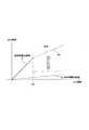
図3では、長時間露光画像信号と短時間露光画像信号の合成処理の説明のために、長時間露光画像信号の入出力輝度特性Aと、短時間露光画像信号の入出力輝度特性Bを示している。
合成処理においては、例えば所定の輝度値を切替ポイントSPとする。そして切替ポイントSPよりも低輝度の画素は、長時間露光画像信号の画素信号を採用する。一方、切替ポイントSPよりも高輝度の画素については、短時間露光画像信号の画素信号を採用する。このとき、長時間露光画像と短時間露光画像との露光比を短時間露光画像に乗算することで双方の画像のレベル合わせを行う。
仮に長時間露光画像と短時間露光画像との露光比が10:1であるとすると、短時間露光画像の露光は長時間露光画像の10分の1である。しかし存在する光の量としては短時間露光画像の輝度信号レベルの10倍は光量がある。したがって短時間露光画像信号に10を乗算することによりレベルを合わせる。
このように短時間露光画像信号についてゲイン乗算を行い、図に示すように長時間露光画像信号特性とレベルの合った特性kBを得る。
結果として、特性A−kBの合成画像を生成する。即ち合成画像では、被写体内で比較的暗い領域は長時間露光画像信号による黒つぶれのない画像が得られ、比較的明るい領域は短時間露光画像信号による白とびのない画像が得られる。FIG. 3 shows the input / output luminance characteristics A of the long exposure image signal and the input / output luminance characteristics B of the short exposure image signal in order to explain the synthesis process of the long exposure image signal and the short exposure image signal. ing.
In the synthesis process, for example, a predetermined luminance value is set as the switching point SP. Then, the pixel signal of the long-time exposure image signal is adopted for the pixel having a lower luminance than the switching point SP. On the other hand, the pixel signal of the short-time exposure image signal is adopted for the pixel having higher luminance than the switching point SP. At this time, the level of both images is adjusted by multiplying the short exposure image by the exposure ratio between the long exposure image and the short exposure image.
If the exposure ratio between the long exposure image and the short exposure image is 10: 1, the exposure of the short exposure image is 1/10 of the long exposure image. However, the amount of light present is 10 times the luminance signal level of the short-time exposure image. Therefore, the level is adjusted by multiplying the short-time exposure image signal by 10.
Thus, gain multiplication is performed on the short-exposure image signal to obtain a characteristic kB whose level matches the long-exposure image signal characteristic as shown in the figure.
As a result, a composite image having the characteristic A-kB is generated. That is, in the composite image, an image without darkening due to the long-time exposure image signal is obtained in a relatively dark area in the subject, and an image without overexposure is obtained from the short-time exposure image signal in a relatively bright area.
なお、出力画像に明るい部分から暗い部分までが含まれるダイナミックレンジが広い被写体を撮像する合成撮像モードの手法としては、上記のように露光時間の異なる明るい画像と暗い画像とを合成する以外にも各種の手法がある。
例えば画素単位に感度を変えて撮像素子から同じ露光条件の信号のみを抜き出して画像を再生し、露光条件の異なる1又は2以上の画像を合成する方法もある。
またはプリズムにより入射光を分けて、撮像素子と、透過する光を全波長に渡って減少させる、つまり入射光量を等しく減少させるNDフィルタ(Neutral Density Filter:光量調節フィルタ)のような減光機能を持つものとを張り合わせた撮像素子から出力される信号を合成する方法などもある。Note that, as a method of the composite imaging mode for imaging a subject with a wide dynamic range in which the output image includes a bright part to a dark part, in addition to synthesizing a bright image and a dark image having different exposure times as described above, There are various methods.
For example, there is a method in which only one or two or more images with different exposure conditions are synthesized by changing the sensitivity in pixel units and extracting only signals with the same exposure condition from the image sensor to reproduce the image.
Or the incident light is divided by the prism, and the image sensor and the dimming function such as ND filter (Neutral Density Filter) that reduces the transmitted light over all wavelengths, that is, reduces the incident light amount equally. There is also a method of synthesizing signals output from an image pickup device that is bonded to what it has.
これらの手法を採用した合成撮像モードによれば、通常撮像モードによる撮像の場合のダイナミックレンジよりも非常に広いダイナミックレンジを得ることができる。従って出力画像に明るい部分から暗い部分までが含まれるダイナミックレンジが広い被写体を撮像することが可能であり、例えば強い外光が差し込む室内,照度差の激しい場所などを撮像する場合に適している。具体的には銀行などの店舗の出入口、または交通状況の把握のために交通道路など、日中、夜間など撮像される時間帯によりダイナミックレンジが大きく異なる場合の撮像には、合成撮像モードが好適となる。 According to the composite imaging mode employing these methods, a dynamic range that is much wider than the dynamic range in the case of imaging in the normal imaging mode can be obtained. Therefore, it is possible to image a subject with a wide dynamic range in which the output image includes a bright part to a dark part, which is suitable for, for example, imaging a room where strong external light is inserted or a place with a large illuminance difference. Specifically, the composite imaging mode is suitable for imaging when the dynamic range varies greatly depending on the time zone that is imaged, such as day and night, such as the entrance of a store such as a bank or a traffic road to grasp traffic conditions. It becomes.
なお以下では、図2(a)のような通常撮像モードでの露光動作を、説明上「通常露光」と言うこととし、図2(b)のような合成撮像モードでの「長時間露光」「短時間露光」と区別する。
また通常露光により得られた露光画像信号を「通常露光画像信号」といい、「長時間露光画像信号」「短時間露光画像信号」と区別する。
Hereinafter, the exposure operation in the normal imaging mode as shown in FIG. 2A will be referred to as “normal exposure” for the sake of explanation, and “long exposure” in the composite imaging mode as shown in FIG. 2B. Distinguish from “short exposure”.
An exposure image signal obtained by normal exposure is called a “normal exposure image signal”, and is distinguished from a “long exposure image signal” and a “short exposure image signal”.
[2.撮像装置の構成]
図1に本例の撮像装置の構成を示す。本例の撮像装置は、撮像光学系1、撮像素子部2,前処理部3、信号処理部4、出力部5,検波部6、タイミングジェネレータ7、光学部品駆動部8、制御部10、操作部11、表示部12を備える。[2. Configuration of imaging device]
FIG. 1 shows the configuration of the imaging apparatus of this example. The imaging apparatus of this example includes an imaging optical system 1, an
撮像光学系1は、レンズや不要な波長を除去する光学フィルタ、絞り1a等の光学部品を備える。被写体から入射された光は撮像光学系1における各光学部品を介して撮像素子部2に導かれる。
撮像素子部2は、例えばCCDセンサアレイ、CMOSセンサアレイなどの固体撮像素子部として構成される。この撮像素子部2は撮像光学系1を介して導かれた光を光電変換し、撮像画像としての電気信号を出力する。本例の場合、撮像素子部2では通常撮像モードと合成撮像モードとで異なる露光処理を行う。即ち通常撮像モードでは図2(a)のように1フィールド期間に所定時間の露光としての通常露光を行って露光画像信号としての電気信号を出力する。一方、合成撮像モードでは、撮像素子部2では1フィールド期間に図2(b)のような長時間露光と短時間露光を行い、長時間露光画像信号と短時間露光画像信号としての電気信号を時分割出力する。
なお撮像素子部2は、固体撮像素子を用いる構成に限られない。例えば撮像管のような非固体撮像素子を用いる構成でも良い。非固体撮像素子についても、メカニカルシャッタ、液晶シャッタ等を利用して、長時間露光、短時間露光を行ったり、通常露光、長時間露光、短時間露光の露光時間を変化させることは可能である。
前処理部3は、いわゆるアナログフロントエンドであり、撮像素子部2から出力される撮像画像としての電気信号に対してCDS(correlated double sampling :相関2重サンプリング)処理、プログラマブルゲインアンプによるゲイン処理、A/D変換処理を行う。そしてこれらの処理を行った露光画像信号を信号処理部4に供給する。即ち通常撮像モードの場合は通常露光画像信号を信号処理部4に供給し、合成撮像モードの場合は長時間露光画像信号と短時間露光画像信号を信号処理部4に供給する。The imaging optical system 1 includes optical components such as a lens, an optical filter that removes unnecessary wavelengths, and a diaphragm 1a. Light incident from the subject is guided to the
The
The
The pre-processing unit 3 is a so-called analog front end, and performs a CDS (correlated double sampling) process on an electrical signal as a captured image output from the
信号処理部4は、通常撮像モード、合成撮像モードのそれぞれに応じて所要の信号処理を行って、撮像画像データを生成する。
通常撮像モードの場合は、入力される通常露光画像信号に対して例えばガンマ補正処理やホワイトバランス処理等を行って撮像画像データとする。
また合成撮像モードの場合は、入力される長時間露光画像信号と短時間露光画像信号について図3で述べた合成処理を行う。即ち時分割的に供給される長時間露光画像信号と短時間露光画像信号のタイミング調整や色バランス補正処理、長時間露光画像信号に対して短時間露光画像信号の輝度レベルを一致させるゲイン処理、および合成処理を行う。また合成画像信号に対するガンマ補正処理やホワイトバランス処理も行って撮像画像データとする。
信号処理部4は、生成した撮像画像データを出力部5及び検波部6に出力する。The signal processing unit 4 performs necessary signal processing according to each of the normal imaging mode and the composite imaging mode, and generates captured image data.
In the normal imaging mode, the input normal exposure image signal is subjected to, for example, gamma correction processing and white balance processing to obtain captured image data.
In the case of the composite imaging mode, the composite processing described in FIG. 3 is performed on the input long exposure image signal and short exposure image signal. That is, the timing adjustment and color balance correction processing of the long-exposure image signal and the short-exposure image signal supplied in a time division manner, the gain processing for matching the luminance level of the short-exposure image signal with the long-exposure image signal, And a synthesis process. Further, gamma correction processing and white balance processing are also performed on the composite image signal to obtain captured image data.
The signal processing unit 4 outputs the generated captured image data to the output unit 5 and the detection unit 6.
出力部5は、信号処理部4からの撮像画像データについて、モニタディスプレイにおける表示のための処理や、或いは外部機器への送信のための処理を行う。 The output unit 5 performs processing for display on the monitor display or processing for transmission to an external device for the captured image data from the signal processing unit 4.
検波部6は、信号処理部4からの撮像画像データについての測光処理を行って輝度積算値を算出し、制御部10に供給する。この場合検波部6では、制御部10からの指示に従って実行する測光方式が選択される。
測光方式としては、中央部重点測光方式、評価測光方式、平均測光方式、部分測光方式などが実行可能とされる。
後述するが、それぞれの測光方式により画像領域内の検波枠が異なるものとなるが、検波部6は、実行する測光方式で設定される検波枠毎の輝度積算値を制御部10に供給することになる。The detection unit 6 performs photometric processing on the captured image data from the signal processing unit 4 to calculate a luminance integrated value, and supplies it to the
As the metering method, a center-weighted metering method, an evaluation metering method, an average metering method, a partial metering method, or the like can be executed.
As will be described later, the detection frames in the image region differ depending on the respective photometry methods, but the detection unit 6 supplies the integrated luminance value for each detection frame set in the photometry method to be executed to the
制御部10は、例えばCPU(Central Processing Unit)、ROM(Read Only Memory)、RAM(Random Access Memory)、フラッシュメモリなどを有するマイクロコンピュータによって構成され、撮像装置の全体の動作を制御する。
特に本例においては制御部10は、撮像処理系としての撮像素子部2,前処理部3,信号処理部4,タイミングジェネレータ7に対して、通常撮像モードと合成撮像モードのそれぞれの撮像動作を実行させる制御を行う。
また制御部10は検波部6に対して測光方式を指定する制御を行う。
また制御部10は露光制御を行う。
制御部10におけるROMには、これらの制御処理を実行させるプログラムが格納されており、該プログラムに基づいて、上記各制御のための必要な演算・制御処理を実行する。The
In particular, in this example, the
Further, the
The
A program for executing these control processes is stored in the ROM of the
タイミングジェネレータ7は、例えばCCDなどの撮像素子部2に必要な動作パルスを生成する。例えば垂直転送のための4相パルス、フィールドシフトパルス、水平転送のための2相パルス、シャッタパルスなどの各種パルスを生成し、撮像素子部2に供給する。このタイミングジェネレータ7により撮像素子部2を駆動(電子シャッタ機能)させることが可能となる。
特にタイミングジェネレータ7は、制御部10から通常撮像モードが指示された場合は、撮像素子部2に図2(a)のように1フィールド期間に所定時間の通常露光を実行させ、また合成撮像モードが指示された場合は、撮像素子部2に図2(b)のように、露光時間が相対的に長い長時間露光と、露光時間が相対的に短い短時間露光を実行させる。
もちろん通常撮像モードでの通常露光時間や、合成撮像モードでの長時間露光時間及び短時間露光時間を可変することも可能である。The
In particular, when the normal imaging mode is instructed from the
Of course, it is also possible to vary the normal exposure time in the normal imaging mode and the long exposure time and the short exposure time in the composite imaging mode.
光学部品駆動部8は、撮像光学系1における光学部品の駆動を行う。本例に関していえば、少なくとも絞り1aを駆動し、入射光量を調節するための駆動回路部とされる。
操作部11、表示部12はユーザインターフェースのために設けられる。操作部11はユーザ操作に応じて操作情報を制御部10に出力する。
表示部12は、制御部10からの指示に応じて動作状態、時間情報、モード情報、メッセージなど、ユーザに提示すべき情報の表示を行う。
なお、操作部11、表示部12は、撮像装置とは別体の機器とされてもよい。また表示部12に表示すべき情報を、キャラクタ画像、文字画像として出力部5において撮像画像データに重畳させ、撮像画像を表示出力するモニタディスプレイ上で表示させるようにしてもよい。
The optical component drive unit 8 drives the optical components in the imaging optical system 1. With regard to this example, at least the diaphragm 1a is driven and a drive circuit unit for adjusting the amount of incident light is used.
The operation unit 11 and the
The
Note that the operation unit 11 and the
[3.撮像装置の全体動作]
以下、本例の撮像装置で実行される動作を説明する。まずここでは撮像装置において通常撮像モードと合成撮像モードで行われる、露光制御を含む全体的な撮像動作を述べる。
図4(a)のステップST1〜ST4は通常撮像モードでの動作の流れを示し、図4(b)のステップST11〜ST14は合成撮像モードでの動作の流れを示している。この図4(a)又は図4(b)の処理が一定間隔で繰り返されることで、撮像中に露光補正が行われる。
[3. Overall operation of imaging device]
Hereinafter, an operation executed by the imaging apparatus of this example will be described. First, an overall imaging operation including exposure control performed in the imaging apparatus in the normal imaging mode and the composite imaging mode will be described.
Figure 4 Step ST1~ST4 of (a) shows a flow of operation in normal imaging mode, step ST11~ST14 in FIG. 4 (b) shows a flow of operation in composite imaging mode. Exposure correction is performed during imaging by repeating the processing of FIG. 4A or FIG. 4B at regular intervals.
まず図4(a)の通常撮像モードでの動作を述べる。
・ステップST1:撮像処理
撮像素子部2で図2(a)のような通常露光が行われ、通常露光画像信号が前処理部で処理されて信号処理部4に供給される。
・ステップST2:信号処理
信号処理部4は、前処理部3でデジタル化された通常露光画像信号について必要な処理を行い、撮像画像データとする。この撮像画像データは、出力部5から例えばモニタディスプレイでの表示のために出力される。First, the operation in the normal imaging mode of FIG.
Step ST1: Imaging Processing Normal exposure as shown in FIG. 2A is performed by the
Step ST2: Signal Processing The signal processing unit 4 performs necessary processing on the normal exposure image signal digitized by the preprocessing unit 3 to obtain captured image data. The captured image data is output from the output unit 5 for display on a monitor display, for example.
・ステップST3:検波処理
撮像画像データは検波部6にも供給される。検波部6は、例えば1フィールド毎に撮像画像データの測光処理を行い、検波枠毎の輝度積算値を生成し、それを制御部10に送信する。図5に検波部6の検波処理を示すが、ステップST31で1フィールドの撮像画像データの画面上で設定した検波枠毎に輝度積算を行う。そしてステップST32で検波枠毎の輝度積算値を制御部10に送信する。
この通常撮像モードの場合、検波部6では中央部重点測光方式、又は評価測光方式で測光を行う。
中央部重点測光方式の検波枠を図6(a)に示す。中央部重点測光方式は、撮像画像エリアARの中央付近を重点的に測光する方式で、画像中心部に主要被写体があることを前提としている。このため検波枠として中央部の検波枠W2と、その周辺部としての検波枠W1を設定する。この場合、検波部6では、検波枠W1,W2のそれぞれの領域で輝度積算値を算出し、制御部10に供給することになる。
評価測光方式の検波枠を図6(b)に示す。評価測光方式では撮像画像エリアARを、例えば水平方向にm個、垂直方向にn個に分割し、図のように検波枠W11〜Wnmを設定する。この場合、検波部6では、検波枠W11〜Wnmのそれぞれの領域で輝度積算値を算出し、制御部10に供給することになる。Step ST3: Detection Processing The captured image data is also supplied to the detection unit 6. For example, the detection unit 6 performs photometric processing of the captured image data for each field, generates a luminance integrated value for each detection frame, and transmits it to the
In the normal imaging mode, the detection unit 6 performs photometry using the center-weighted photometry method or the evaluation photometry method.
FIG. 6A shows a detection frame of the center-weighted photometry method. The center-weighted metering method is a method that focuses light on the vicinity of the center of the captured image area AR, and is premised on that the main subject is in the center of the image. Therefore, a detection frame W2 at the center is set as the detection frame, and a detection frame W1 as the peripheral portion is set. In this case, the detection unit 6 calculates the integrated luminance value in each region of the detection frames W1 and W2 and supplies it to the
FIG. 6B shows a detection frame of the evaluation photometry method. In the evaluation photometry method, for example, the captured image area AR is divided into m pieces in the horizontal direction and n pieces in the vertical direction, and detection frames W11 to Wnm are set as shown in the figure. In this case, the detection unit 6 calculates the integrated luminance value in each region of the detection frames W11 to Wnm and supplies it to the
・ステップST4:露光制御処理
制御部10は、検波枠毎の輝度積算値を用いて露光制御を行う。
検波部6で中央部重点測光方式で測光が行われ、図6(a)の検波枠W1,W2の輝度積算値が供給される場合、中央部の検波枠W2の輝度積算値に重み付けを行って単位面積あたりの輝度を求める。例えば検波枠W2の重みを100%とした場合は、検波枠W1を20%として加重平均を行い、単位面積あたりの輝度を求める。
また、検波部6で評価測光方式で測光が行われ、図6(b)の検波枠W11〜Wnmの輝度積算値が供給される場合、各輝度積算値を用いた所定のアルゴリズム演算を行って単位面積あたりの輝度を求める。
これらの処理で、現在の単位面積あたりの輝度を求めたら、その単位面積当たりの輝度と目標輝度との差分として露光制御量を算出し、露光制御量に応じた露光制御を行う。
具体的には絞り1aの開口量、撮像素子部2の通常露光時間、前処理部3のPGA(プログラマブルゲインアンプ)のゲインについて、それぞれ必要な制御量を計算する。そして光学部品駆動部8に絞り1aの駆動を実行させ、またタイミングジェネレータ7に通常露光の露光時間を指示し、また前処理部3にPGAのゲインを指示する。なお、これらの3つの制御を全て行う他、これらの内の1つ又は2つの制御を行うようにしても良い。
Step ST4: Exposure control processing The
When the detection unit 6 performs photometry in the center-weighted photometry method and supplies the luminance integrated value of the detection frames W1 and W2 in FIG. 6A, the luminance integrated value of the detection frame W2 in the center is weighted. To obtain the luminance per unit area. For example, when the weight of the detection frame W2 is set to 100%, the weighting average is performed with the detection frame W1 set to 20%, and the luminance per unit area is obtained.
When the detection unit 6 performs photometry using the evaluation photometry method and supplies the luminance integrated values of the detection frames W11 to Wnm in FIG.6B , a predetermined algorithm calculation using each luminance integrated value is performed. Find the luminance per unit area.
In these processes, when the current luminance per unit area is obtained, an exposure control amount is calculated as a difference between the luminance per unit area and the target luminance, and exposure control corresponding to the exposure control amount is performed.
Specifically, necessary control amounts are calculated for the aperture amount of the diaphragm 1a, the normal exposure time of the
次に図4(b)の合成撮像モードでの動作を述べる。
・ステップST11:撮像処理
撮像素子部2で図2(b)のような長時間露光と短時間露光を実行する。即ちタイミングジェネレータ7は、1フィールド期間内に異なる二つの電子シャッタースピードを設定することが可能であり、1フィールド期間に図(b)の長時間露光と短時間露光を撮像素子部2に実行させる。これにより露光量の違う二つの撮像画像信号(例えば露光時間1/64秒の長時間露光画像信号と、露光時間1/2000秒の短時間露光画像信号)が得られる。上記のとおり、長時間露光画像信号と短時間露光画像信号はそれぞれ前処理部3で処理されて信号処理部4に供給される。
・ステップST12:信号処理
信号処理部4は、前処理部3でデジタル化された長時間露光画像信号と短時間露光画像信号を図3で述べた手法で合成し、ダイナミックレンジを拡大させた合成画像としての撮像画像データを生成する。この撮像画像データは、出力部5から例えばモニタディスプレイでの表示のために出力される。Next, the operation in the composite imaging mode of FIG.
Step ST11: Imaging Processing The
Step ST12: Signal Processing The signal processing unit 4 combines the long exposure image signal and the short exposure image signal digitized by the preprocessing unit 3 by the method described in FIG. Captured image data as an image is generated. The captured image data is output from the output unit 5 for display on a monitor display, for example.
・ステップST13:検波処理
撮像画像データは検波部6にも供給される。検波部6は、上記図5のステップST31、ST32で述べたように、1フィールド毎に撮像画像データの測光処理を行い、検波枠毎の輝度積算値を生成し、それを制御部10に送信する。
この合成撮像モードの場合、検波部6では平均測光方式で測光を行う。
平均測光方式の検波枠を図7(a)に示す。平均測光(全面測光)は、撮像画像の全体で測光を行い、その平均値を輝度として扱う方式である。従って検波枠W1として撮像画像エリアARの全体を1つの検波枠とする。検波部6は、検波枠W1として撮像画像エリアARの全体での輝度積算値を算出し、制御部10に供給することになる。Step ST13: Detection Processing The captured image data is also supplied to the detection unit 6. As described in steps ST31 and ST32 of FIG. 5 above, the detection unit 6 performs photometric processing of the captured image data for each field, generates a luminance integrated value for each detection frame, and transmits it to the
In the case of this composite imaging mode, the detector 6 performs photometry using the average photometry method.
FIG. 7A shows the detection frame of the average photometry method. Average photometry (entire photometry) is a method in which photometry is performed on the entire captured image and the average value is treated as luminance. Therefore, the entire captured image area AR is set as one detection frame as the detection frame W1. The detection unit 6 calculates the luminance integrated value in the entire captured image area AR as the detection frame W <b> 1 and supplies it to the
ステップST14:露光制御処理
制御部10は、平均測光方式の検波枠W1の輝度積算値を用いて露光制御を行う。
例えば検波枠W1の輝度積算値から、単位面積としての平均値の輝度を求める。
そして現在の単位面積あたりの輝度を求めたら、その単位面積当たりの輝度と目標輝度との差分として露光制御量を算出し、露光制御量に応じた露光制御を行う。
この場合、具体的には絞り1aの開口量、撮像素子部2の長時間露光時間と短時間露光時間、前処理部3のPGA(プログラマブルゲインアンプ)のゲインについて、それぞれ必要な制御量を計算する。そして光学部品駆動部8に絞り1aの駆動を実行させ、またタイミングジェネレータ7に長時間露光と短時間露光の露光時間を指示し、また前処理部3にPGAのゲインを指示する。なお、これらの3つの制御を全て行う他、これらの内の1つ又は2つの制御を行うようにしても良い。
Step ST14: Exposure Control Processing The
For example, the average luminance as a unit area is obtained from the luminance integrated value of the detection frame W1.
When the luminance per unit area is obtained, an exposure control amount is calculated as a difference between the luminance per unit area and the target luminance, and exposure control is performed according to the exposure control amount.
In this case, specifically, necessary control amounts are calculated for the aperture amount of the diaphragm 1a, the long exposure time and the short exposure time of the image
[4.制御部の処理例I]
通常撮像モードと合成撮像モードのそれぞれにおいて図4(a)(b)の動作が行われるようにするための制御部10の処理例を図8で説明する。
制御部10は、ステップF101,F102で合成撮像モード又は通常撮像モードでの撮像開始のトリガを監視する。例えばユーザの撮像開始操作や外部機器からの撮像開始の指示などとしての撮像開始のトリガ発生を監視する。
[4. Control unit processing example I]
A processing example of the
The
通常撮像モードでの撮像動作が開始される場合、制御部10は処理をステップF102からF105に進め、タイミングジェネレータ7,前処理部3,信号処理部4に対して通常撮像モードでの動作開始を指示する。
またステップF106で、検波部6に中央部重点測光方式又は評価測光方式を指示する。
これによって、図4(a)のステップST1、ST2、ST3で述べた動作が各部で開始されることになる。When the imaging operation in the normal imaging mode is started, the
In step F106, the detection unit 6 is instructed to use the center-weighted metering method or the evaluation metering method.
As a result, the operations described in steps ST1, ST2, and ST3 in FIG.
一方、合成撮像モードでの撮像動作が開始される場合、制御部10は処理をステップF101からF103に進め、タイミングジェネレータ7,前処理部3,信号処理部4に対して合成撮像モードでの動作開始を指示する。
またステップF104で、検波部6に平均測光方式を指示する。
これによって、図4(b)のステップST11、ST12、ST13で述べた動作が各部で開始されることになる。On the other hand, when the imaging operation in the composite imaging mode is started, the
In step F104, the detection unit 6 is instructed about the average photometry method.
As a result, the operations described in steps ST11, ST12, and ST13 in FIG. 4B are started in each unit.
通常撮像モード又は合成撮像モードで撮像動作が開始された以降は、ステップF107で撮像終了となるまで、制御部10は1フレーム期間毎に、ステップF108、F109、F110で露光制御処理を繰り返す。即ち図4(a)のステップST4又は図4(b)のステップST14の処理である。
ステップF108で制御部10は、検波部6からの各検波枠毎の輝度積算値を入力し、検波部6で実行させている測光方式に応じて、輝度積算値から単位面積あたりの輝度を算出する。
ステップF109で制御部10は、単位面積当たりの輝度と目標輝度との差分として露光制御量を算出する。即ち絞り1aの開口量、撮像素子部2の露光時間(通常露光時間、又は長時間露光時間と短時間露光時間)、前処理部3のPGAゲインについて、制御量を計算する。
そしてステップF110で制御部10は、算出した各制御量に基づいて、光学部品駆動部8に絞り1aの駆動を実行させ、またタイミングジェネレータ7に露光時間を指示し、また前処理部3にPGAのゲインを指示する。After the imaging operation is started in the normal imaging mode or the composite imaging mode, the
In step F108, the
In step F109, the
In step F110, the
制御部10はステップF107で、ユーザ操作その他による終了トリガを検知したら、処理をステップF111に進め、各部に撮像動作を終了させ、一連の撮像動作制御を終える。
制御部10が、このような処理を行うことで、図4(a)(b)に示した通常撮像モードや合成撮像モードとしての撮像動作が実現される。
When the
When the
[5.制御部の処理例II]
上記図8で示した制御部10の処理例Iによれば、通常撮像モードの場合は検波部6で中央部重点測光方式又は評価測光方式で測光が行われ、合成撮像モードの場合は検波部6で平均測光方式で測光が行われる。
このような動作を行うとともに、検波部6で部分測光方式を行うようにする処理例も考えられる。これを処理例IIとして説明する。[5. Control unit processing example II]
According to the processing example I of the
An example of processing in which such an operation is performed and the partial photometry method is performed in the detection unit 6 is also conceivable. This will be described as Processing Example II.
部分測光(スポット測光ともいわれる)は、測光範囲を画面のごく狭い範囲に限定して行う測光方式の事で、被写体の一部を露出の基にしたい場合に使用する。測光範囲(検波枠)は撮像装置のユーザにより指定される。
例えば図7(b)に部分測光方式の検波枠W1を示す。このように撮像画像エリアAR内で、ユーザが指定した領域が検波枠W1とされる。検波部6で部分測光が行われる場合、検波部6で、指定された検波枠W1で輝度積算値を算出し、その輝度積算値を制御部10に供給することになる。
この部分測光方式は自動的に適用される測光方式ではなく、撮像装置のユーザが撮像画像エリア内で特定のエリアを指定し、そこを適正露光させるための処理である。したがって合成撮像モード、通常撮像モードに関わらず、ユーザが部分測光を指定した場合は、部分測光を実施することが適切となる。Partial metering (also called spot metering) is a metering method that limits the metering range to a very narrow range on the screen, and is used when you want to use a part of the subject as the basis for exposure. The photometric range (detection frame) is designated by the user of the imaging device.
For example, FIG. 7B shows a partial photometry detection frame W1. Thus, the area designated by the user in the captured image area AR is the detection frame W1. When partial photometry is performed by the detection unit 6, the detection unit 6 calculates a luminance integrated value in the designated detection frame W <b> 1 and supplies the luminance integration value to the
This partial photometry method is not a photometry method that is automatically applied, but is a process for the user of the imaging apparatus to designate a specific area within the captured image area and to expose it appropriately. Therefore, regardless of the composite imaging mode and the normal imaging mode, when the user designates partial photometry, it is appropriate to perform partial photometry.
部分測光を考慮した制御部10の処理を図9に示す。
なお図9においてステップF101〜F111は図8と同様の処理であり、重複説明を避ける。この図9は、図8の処理に、ステップF201,F202,F203を追加したものである。The processing of the
In FIG. 9, steps F101 to F111 are the same processing as in FIG. FIG. 9 is obtained by adding steps F201, F202, and F203 to the process of FIG.
ステップF103で合成撮像モードで撮像動作を開始させる場合、制御部10は、ステップF201で、ユーザ操作により部分測光が指定されているか否かを判断する。そして部分測光が指示されていなければステップF104に進んで検波部6に平均測光方式を指示するが、部分測光が指示されていたら、ステップF203に進んで検波部6に部分測光方式を指示する。
またステップF105で通常撮像モードで撮像動作を開始させる場合、制御部10は、ステップF202で、ユーザ操作により部分測光が指定されているか否かを判断する。そして部分測光が指示されていなければステップF106に進んで検波部6に中央部重点測光方式又は評価測光方式を指示するが、部分測光が指示されていたら、ステップF203に進んで検波部6に部分測光方式を指示する。When the imaging operation is started in the composite imaging mode in Step F103, the
When the imaging operation is started in the normal imaging mode in step F105, the
そしてステップF107以降の処理を図8と同様に実行する。なお部分測光が実行されている場合は、ステップF108では、部分測光方式に応じた演算処理で単位面積あたりの輝度を算出する。即ち部分測光方式の検波枠W1の輝度積算値から、単位面積あたりの平均輝度を算出する。
この図9の処理例によれば、通常撮像モードの場合は検波部6で中央部重点測光方式又は評価測光方式で測光が行われ、合成撮像モードの場合は検波部6で平均測光方式で測光が行われることを基本としつつ、ユーザの指定によって検波部6で部分測光方式が実行されることになる。
And the process after step F107 is performed similarly to FIG. If partial photometry is being performed, in step F108, the luminance per unit area is calculated by arithmetic processing according to the partial photometry method. That is, the average luminance per unit area is calculated from the luminance integrated value of the partial photometry detection frame W1.
According to the processing example of FIG. 9, in the normal imaging mode, the detection unit 6 performs photometry using the center-weighted photometry method or the evaluation photometry method, and in the composite imaging mode, the detection unit 6 performs photometry using the average photometry method. The partial photometry method is executed by the detection unit 6 in accordance with the user's designation.
[6.制御部の処理例III]
次に制御部10の処理例IIIとして、特に監視カメラとしての撮像装置に好適な例を述べる。
監視カメラ(セキュリティカメラ)では、合成撮影モードで平均測光をしている最中に撮像画像内の特定エリアで異常(侵入など)を検出した場合、その領域をより鮮明に撮像したという要望がある。そのような場合ユーザーからの指示または自動設定により部分測光に切り替えることが適切となる。[6. Control unit processing example III]
Next, as a processing example III of the
In a surveillance camera (security camera), when an abnormality (intrusion, etc.) is detected in a specific area in a captured image during average metering in composite shooting mode, there is a demand for clearer imaging of that area. . In such a case, it is appropriate to switch to partial photometry according to an instruction from the user or automatic setting.
なお、この処理例IIIの実行のため、撮像装置の構成として図10のような例が考えられる。図10は、図1の構成に異常検知部9を追加したものである。
異常検知部9には、信号処理部4からの撮像画像データが供給される。そして異常検知部9は、撮像画像データについてモーションディテクト(Motion Detect:動き検知)処理を行い、撮像画像内で異常があった撮像画像エリアの特定部分を検出する。
モーションディテクト処理の手法としては、例えば予め撮像画像エリアAR内で検出枠を何点か指定しておき、その検出枠に輝度変化が発生することを検知するという処理が考えられる。また特に検出枠を設定せず、画像解析或いはフレーム比較により、動きのあった画面内の領域を特定するという処理も可能である。人の画像を検出し、その動きの早さによって異常を判定しても良い。
異常検知部9は、このようなモーションディテクト処理により、異常発生(例えば人の進入など)と判断した場合、制御部10に異常検出を通知するとともに、異常を検知した画像内の領域を通知する。In order to execute the processing example III, an example as shown in FIG. 10 can be considered as the configuration of the imaging apparatus. FIG. 10 is obtained by adding an abnormality detection unit 9 to the configuration of FIG.
The abnormality detection unit 9 is supplied with captured image data from the signal processing unit 4. Then, the abnormality detection unit 9 performs a motion detect process on the captured image data, and detects a specific portion of the captured image area where there is an abnormality in the captured image.
As a method of the motion detection process, for example, a process of designating several detection frames in the captured image area AR in advance and detecting the occurrence of a luminance change in the detection frame can be considered. In addition, it is possible to specify a region in the screen that has moved by image analysis or frame comparison without setting a detection frame. An image of a person may be detected, and abnormality may be determined based on the speed of movement.
When the abnormality detection unit 9 determines that an abnormality has occurred (for example, the entry of a person) by such motion detection processing, the abnormality detection unit 9 notifies the
このように異常検知部9を備えた場合の制御部10の処理例を図11に示す。なお図11においてステップF101〜F111は図8と同様の処理であり、またステップF201,F202,F203は図9と同様である。即ちこの図11の処理は、図9の処理にステップF301,F302を追加したものである。 FIG. 11 shows a processing example of the
図9の場合と同様、この図11の処理例でば、通常撮像モードの場合は検波部6で中央部重点測光方式又は評価測光方式で測光が行われ、合成撮像モードの場合は検波部6で平均測光方式で測光が行われることを基本としつつ、ユーザの指定によって検波部6で部分測光方式が実行される。
そして合成撮像モード又は通常撮像モードで撮像動作が開始された後は、ステップF108〜F110で露光制御処理が行われるが、このとき制御部10はステップF301で、異常検知部9からの異常検出信号が入力されたか否かを判断する。
異常検出信号が入力されなければ、1フィールド毎に露光制御処理を繰り返す。
異常検出信号が入力された場合は、ステップF301からF302に進み、検波部6に対して、画像上での異常検知部分を検波枠とする部分測光方式を指示する。
これによって検波部6では、それまでの測光方式から、異常発生時の部分測光方式に切り換える。つまり異常検知部9から通知される領域を検波枠W1として部分測光を行い、その輝度積算値を制御部10に供給する。As in the case of FIG. 9, in the processing example of FIG. 11, in the normal imaging mode, the detection unit 6 performs photometry using the center-weighted metering method or the evaluation metering method, and in the composite imaging mode, the detection unit 6. Thus, the partial photometry method is executed by the detector 6 based on the user's designation while the photometry is basically performed by the average photometry method.
After the imaging operation is started in the composite imaging mode or the normal imaging mode, the exposure control process is performed in steps F108 to F110. At this time, the
If no abnormality detection signal is input, the exposure control process is repeated for each field.
When an abnormality detection signal is input, the process proceeds from step F301 to F302, and the detection unit 6 is instructed to perform a partial photometry method using an abnormality detection portion on the image as a detection frame.
As a result, the detection unit 6 switches from the previous photometry method to the partial photometry method when an abnormality occurs. That is, partial photometry is performed using the region notified from the abnormality detection unit 9 as the detection frame W <b> 1, and the integrated luminance value is supplied to the
制御部は、引き続きステップF108〜F110で露光制御処理を行うが、この場合ステップF108では、部分測光方式での検波枠W1の輝度積算値から単位面積あたりの輝度を算出し、ステップF109,F110で露光制御を行うことになる。 The control unit continues to perform exposure control processing in steps F108 to F110. In this case, in step F108, the luminance per unit area is calculated from the luminance integrated value of the detection frame W1 in the partial photometry method, and in steps F109 and F110. Exposure control is performed.
このような処理例IIIによれば、通常撮像モードの場合は検波部6で中央部重点測光方式又は評価測光方式で測光が行われ、合成撮像モードの場合は検波部6で平均測光方式で測光が行われることを基本としつつ、ユーザの指定によって検波部6で部分測光方式が実行されることになる。そしてさらに、被写体に異常が発生した場合は、その異常発生部分を検波枠とする部分測光方式が実行され、異常発生部分に対して最適な露光制御が行われることになる。
なお、図10では異常検知部9が撮像装置の内部に設けられる例を示したが、撮像画像データを外部の異常検知装置(画像解析装置等)に供給し、その外部の異常検知装置から異常検出信号や異常発生領域の情報を入力するようにしてもよい。
また、ステップF301で異常検出となった場合、制御部10は表示部2によりユーザに対してメッセージ出力を行うようにしてもよい。
例えば「異常検出されたので部分測光に切り換えますか?」という趣旨のメッセージ表示を行い、ユーザの指示に応じて部分測光に切り換えるようにしてもよい。
また、図11では図9の処理例にステップF301,F302を追加した処理としたが、図8の処理例にステップF301,F302を追加した処理としてもよい。
According to the processing example III, in the normal imaging mode, the detection unit 6 performs photometry using the center-weighted metering method or the evaluation metering method, and in the composite imaging mode, the detection unit 6 performs metering using the average metering method. The partial photometry method is executed by the detection unit 6 in accordance with the user's designation. Further, when an abnormality occurs in the subject, a partial photometry method using the abnormality occurrence portion as a detection frame is executed, and optimal exposure control is performed on the abnormality occurrence portion.
Although FIG. 10 shows an example in which the abnormality detection unit 9 is provided inside the imaging apparatus, the captured image data is supplied to an external abnormality detection apparatus (such as an image analysis apparatus) and an abnormality is detected from the external abnormality detection apparatus. You may make it input the information of a detection signal and an abnormality generation area.
Further, when an abnormality is detected in step F301, the
For example, a message may be displayed to the effect that “Do you want to switch to partial metering because an abnormality has been detected?” And switch to partial metering in response to a user instruction.
In FIG. 11, the processing example in which steps F <b> 301 and F <b> 302 are added to the processing example in FIG. 9 is described, but the processing example in which steps F <b> 301 and F <b> 302 are added to the processing example in FIG.
[7.実施の形態の効果、及びプログラム]
以上の実施の形態によれば、通常撮像モードと、ワイドダイナミックレンジを得るための合成撮像モードとの各場合において測光方式を切り替えることで、通常撮像モード、合成撮像モードのそれぞれに適した測光を行うことができる。特に通常撮像モードの場合は中央部重点測光方式又は評価測光方式とし、合成撮像モードの場合は平均測光方式とすることが適切となる。
そしてそのような適切な測光に基づいて露光制御を行うことで、ダイナミックレンジの狭い通常撮影モードの画質を損なうことなく、合成撮影モードでの自動露光の性能を向上させることができる。
また、上記図9の処理例IIによれば、ユーザの指示に応じて部分測光を行い、画像内の特定の領域に注目した露光制御も可能となる。
また、上記図11の処理例IIIによれば、異常発生に応じて、異常部分を検波枠とする部分測光方式が実行され、画像内の異常発生領域に適応した露光制御も可能となる。[7. Effects of Embodiment and Program]
According to the above embodiment, by switching the photometry method in each case of the normal imaging mode and the composite imaging mode for obtaining a wide dynamic range, photometry suitable for each of the normal imaging mode and the composite imaging mode can be performed. It can be carried out. In particular, it is appropriate to use the center-weighted metering method or the evaluation metering method in the normal imaging mode, and the average metering method in the composite imaging mode.
By performing exposure control based on such appropriate photometry, it is possible to improve the performance of automatic exposure in the composite shooting mode without impairing the image quality in the normal shooting mode with a narrow dynamic range.
In addition, according to the processing example II in FIG. 9 described above, it is possible to perform exposure control in which partial photometry is performed in accordance with a user instruction and attention is paid to a specific region in the image.
Further, according to the processing example III in FIG. 11, a partial photometry method using the abnormal portion as a detection frame is executed in accordance with the occurrence of abnormality, and exposure control adapted to the abnormality occurrence region in the image is also possible.
なお、本発明は動画撮像を行うカメラシステムに適用できるが、静止画撮像を行うカメラシステムにも適用できる。静止画撮像の場合であっても、例えば撮像タイミングに至までのモニタリング中に、撮像モードに応じた測光方式の切換や、それに基づく露光制御を行えばよい。 The present invention can be applied to a camera system that captures moving images, but can also be applied to a camera system that captures still images. Even in the case of still image capturing, for example, during monitoring up to the image capturing timing, switching of the photometric method according to the image capturing mode and exposure control based on it may be performed.
実施の形態のプログラムは、上述した制御部10の処理のプログラムである。即ち図8、図9,図11のような各種処理例をマイクロコンピュータ(演算処理装置)である制御部10に実行させるプログラムである。
このようなプログラムは、パーソナルコンピュータや、撮像装置等の機器に内蔵されている記録媒体としてのHDDや、CPUを有するマイクロコンピュータ内のROMやフラッシュメモリ等に予め記録しておくことができる。
あるいはまた、フレキシブルディスク、CD−ROM(Compact Disc Read Only Memory)、MO(Magnet optical)ディスク、DVD(Digital Versatile Disc)、ブルーレイディスク、磁気ディスク、半導体メモリ、メモリカードなどのリムーバブル記録媒体に、一時的あるいは永続的に格納(記録)しておくことができる。このようなリムーバブル記録媒体は、いわゆるパッケージソフトウェアとして提供することができる。
また、本発明のプログラムは、リムーバブル記録媒体からパーソナルコンピュータ等にインストールする他、ダウンロードサイトから、LAN(Local Area Network)、インターネットなどのネットワークを介してダウンロードすることもできる。The program according to the embodiment is a program for processing of the
Such a program can be recorded in advance in an HDD as a recording medium incorporated in a device such as a personal computer or an imaging apparatus, a ROM in a microcomputer having a CPU, a flash memory, or the like.
Alternatively, it may be temporarily stored on a removable recording medium such as a flexible disk, CD-ROM (Compact Disc Read Only Memory), MO (Magnet optical) disk, DVD (Digital Versatile Disc), Blu-ray disk, magnetic disk, semiconductor memory, memory card, etc. Can be stored (recorded) or permanently. Such a removable recording medium can be provided as so-called package software.
The program of the present invention can be downloaded from a removable recording medium to a personal computer or the like, or can be downloaded from a download site via a network such as a LAN (Local Area Network) or the Internet.
1 撮像光学系、1a 絞り、2 撮像素子部、3 前処理部、4 信号処理部、5 出力部、6 検波部、7 タイミングジェネレータ、8 光学部品駆動部、9 異常検知部、10 制御部、11 操作部、12 表示部 DESCRIPTION OF SYMBOLS 1 Imaging optical system, 1a Aperture, 2 Imaging element part, 3 Preprocessing part, 4 Signal processing part, 5 Output part, 6 Detection part, 7 Timing generator, 8 Optical component drive part, 9 Abnormality detection part, 10 Control part, 11 Operation part, 12 Display part
Claims (9)
Translated fromJapanese上記撮像処理部で生成された撮像画像データについて測光処理を行う検波部と、
上記通常撮像モードか上記合成撮像モードかに応じて、上記検波部の測光処理方式の切換制御を行う制御部と、
を備えた撮像装置。An imaging operation in a normal imaging mode in which signal processing is performed onone exposure image signal to generate captured image data, a long exposure image signal with a relatively long exposure time, and a short exposure image signal with a relatively short exposure time An imaging processing unit capable of selectively executing an imaging operation in a composite imaging mode for generating captured image data by performing signal processing including synthesis processing of the long-time exposure image signal and the short-time exposure image signal. ,
A detector for performing photometric processing on the captured image data generated by the imaging processor;
A control unit that performs switching control of the photometric processing method of the detection unit according to the normal imaging mode or the composite imaging mode;
An imaging apparatus comprising:
上記制御部は、上記通常撮像モード又は上記合成撮像モードでの撮像動作の際に、上記異常検知部により異常が検知された場合は、上記検波部の測光処理方式を部分測光方式に制御する請求項1に記載の撮像装置。An abnormality detection unit for detecting an abnormality of the subject from the captured image data obtained by the imaging processing unit;
The control unit, when the imaging operation in the normal imaging mode or the combined image capturing mode, if an abnormality is detected by the abnormality detection unit,that controls the photometric processing method of the detection unit in the partial area metering method The imaging device according to claim 1.
上記通常撮像モードで撮像動作を行う際には、上記撮像処理部で生成された撮像画像データについて中央部重点測光方式又は評価測光方式により測光処理を行い、
上記合成撮像モードで撮像動作を行う際には、上記撮像処理部で生成された撮像画像データについて平均測光方式により測光処理を行う測光方法。An imaging operation in a normal imaging mode in which signal processing is performed onone exposure image signal to generate captured image data, a long exposure image signal with a relatively long exposure time, and a short exposure image signal with a relatively short exposure time Photometry of an imaging apparatus capable of selectively performing imaging operation in a composite imaging mode in which captured image data is generated by performing signal processing including synthesis processing of the long exposure image signal and the short exposure image signal. As a method
When performing an imaging operation in the normal imaging mode, photometric processing is performed on the captured image data generated by the imaging processing unit using the center-weighted metering method or the evaluation metering method,
When performing an imaging operation in the combined image capturing mode, the rowcormorants metering method photometric processing by averaging metering method for capturing image data generated by the imaging processing unit.
上記撮像処理部で生成された撮像画像データについて測光処理を行う検波部と、
を備えた撮像装置における撮像画像データの輝度算出方法として、
上記通常撮像モードか上記合成撮像モードかに応じて、上記検波部の測光処理方式の切換制御を行うステップと、
上記検波部の測光処理により得られた値を入力し、入力した値に対して、上記検波部で実行された測光処理方式に応じた演算を行って単位面積当たりの輝度値を算出するステップと、
を備えた輝度算出方法。An imaging operation in a normal imaging mode in which signal processing is performed onone exposure image signal to generate captured image data, a long exposure image signal with a relatively long exposure time, and a short exposure image signal with a relatively short exposure time An imaging processing unit capable of selectively executing an imaging operation in a composite imaging mode for generating captured image data by performing signal processing including synthesis processing of the long-time exposure image signal and the short-time exposure image signal. ,
A detector for performing photometric processing on the captured image data generated by the imaging processor;
As a luminance calculation method of captured image data in an imaging apparatus equipped with
Performing switching control of the photometric processing method of the detection unit according to the normal imaging mode or the composite imaging mode;
A step of inputting a value obtained by the photometric processing of the detection unit and calculating a luminance value per unit area by performing an operation according to the photometric processing method executed by the detection unit on the input value; ,
A luminance calculation method comprising:
上記撮像処理部で生成された撮像画像データについて測光処理を行う検波部と、
を備えた撮像装置における撮像画像データの輝度算出のためのプログラムとして、
上記通常撮像モードか上記合成撮像モードかに応じて、上記検波部の測光処理方式の切換制御を行うステップと、
上記検波部の測光処理により得られた値を入力し、入力した値に対して、上記検波部で実行された測光処理方式に応じた演算を行って単位面積当たりの輝度値を算出するステップと、
を演算処理装置に実行させるプログラム。An imaging operation in a normal imaging mode in which signal processing is performed onone exposure image signal to generate captured image data, a long exposure image signal with a relatively long exposure time, and a short exposure image signal with a relatively short exposure time An imaging processing unit capable of selectively executing an imaging operation in a composite imaging mode for generating captured image data by performing signal processing including synthesis processing of the long-time exposure image signal and the short-time exposure image signal. ,
A detector for performing photometric processing on the captured image data generated by the imaging processor;
As a program for calculating the brightness of captured image data in an imaging apparatus equipped with
Performing switching control of the photometric processing method of the detection unit according to the normal imaging mode or the composite imaging mode;
A step of inputting a value obtained by the photometric processing of the detection unit and calculating a luminance value per unit area by performing an operation according to the photometric processing method executed by the detection unit on the input value; ,
A program that causes an arithmetic processing unit to execute.
Priority Applications (7)
| Application Number | Priority Date | Filing Date | Title |
|---|---|---|---|
| JP2007070443AJP4306752B2 (en) | 2007-03-19 | 2007-03-19 | Imaging device, photometry method, luminance calculation method, program |
| US12/042,746US7916209B2 (en) | 2007-03-19 | 2008-03-05 | Image capturing apparatus, light metering method, luminance calculation method, and program |
| TW097107919ATWI394433B (en) | 2007-03-19 | 2008-03-06 | Image capturing apparatus, light metering method, luminance calculation method, and program |
| DE602008003145TDE602008003145D1 (en) | 2007-03-19 | 2008-03-13 | Image pickup device, light metering method, luminosity calculation method and program |
| EP08152686AEP1973341B1 (en) | 2007-03-19 | 2008-03-13 | Image capturing apparatus, light metering method, luminance calculation method, and program |
| KR1020080024790AKR101419947B1 (en) | 2007-03-19 | 2008-03-18 | PHOTOGRAPHING APPARATUS, METERING METHOD, Luminance Computing Method, and Storage Medium |
| CN2008100871257ACN101272458B (en) | 2007-03-19 | 2008-03-19 | Image capturing apparatus, light metering method, luminance calculation method |
Applications Claiming Priority (1)
| Application Number | Priority Date | Filing Date | Title |
|---|---|---|---|
| JP2007070443AJP4306752B2 (en) | 2007-03-19 | 2007-03-19 | Imaging device, photometry method, luminance calculation method, program |
Publications (2)
| Publication Number | Publication Date |
|---|---|
| JP2008236142A JP2008236142A (en) | 2008-10-02 |
| JP4306752B2true JP4306752B2 (en) | 2009-08-05 |
Family
ID=39561977
Family Applications (1)
| Application Number | Title | Priority Date | Filing Date |
|---|---|---|---|
| JP2007070443AExpired - Fee RelatedJP4306752B2 (en) | 2007-03-19 | 2007-03-19 | Imaging device, photometry method, luminance calculation method, program |
Country Status (7)
| Country | Link |
|---|---|
| US (1) | US7916209B2 (en) |
| EP (1) | EP1973341B1 (en) |
| JP (1) | JP4306752B2 (en) |
| KR (1) | KR101419947B1 (en) |
| CN (1) | CN101272458B (en) |
| DE (1) | DE602008003145D1 (en) |
| TW (1) | TWI394433B (en) |
Families Citing this family (33)
| Publication number | Priority date | Publication date | Assignee | Title |
|---|---|---|---|---|
| US8698924B2 (en)* | 2007-03-05 | 2014-04-15 | DigitalOptics Corporation Europe Limited | Tone mapping for low-light video frame enhancement |
| US9307212B2 (en)* | 2007-03-05 | 2016-04-05 | Fotonation Limited | Tone mapping for low-light video frame enhancement |
| US8264594B2 (en)* | 2007-07-25 | 2012-09-11 | Candela Microsystems (S) Pte. Ltd. | Exposure control for an imaging system |
| JP4424402B2 (en)* | 2007-09-28 | 2010-03-03 | ソニー株式会社 | Imaging apparatus, imaging control method, and imaging control program |
| JP5181294B2 (en)* | 2008-03-31 | 2013-04-10 | 富士フイルム株式会社 | Imaging system, imaging method, and program |
| JP5094607B2 (en)* | 2008-07-16 | 2012-12-12 | キヤノン株式会社 | Imaging apparatus, control method thereof, and program |
| CN101651785B (en)* | 2008-08-15 | 2012-11-21 | 鸿富锦精密工业(深圳)有限公司 | Imaging device and imaging method |
| TWI386047B (en)* | 2008-08-29 | 2013-02-11 | Hon Hai Prec Ind Co Ltd | Imaging device and method thereof |
| JP4561912B2 (en)* | 2008-09-12 | 2010-10-13 | ソニー株式会社 | Imaging apparatus, imaging method, and program |
| JP4770907B2 (en)* | 2008-10-21 | 2011-09-14 | ソニー株式会社 | Imaging apparatus, imaging method, and program |
| WO2011143508A2 (en)* | 2010-05-12 | 2011-11-17 | Li-Cor, Inc. | Wide dynamic range imaging |
| JP5257487B2 (en)* | 2011-05-30 | 2013-08-07 | ソニー株式会社 | Imaging apparatus, imaging method, and program |
| TWI443436B (en) | 2011-07-29 | 2014-07-01 | Ability Entpr Co Ltd | Flash light module and image capturing system |
| JP5683418B2 (en)* | 2011-09-08 | 2015-03-11 | オリンパスイメージング株式会社 | Photographing equipment and photographing method |
| JP6124538B2 (en)* | 2012-09-06 | 2017-05-10 | キヤノン株式会社 | IMAGING DEVICE, IMAGING DEVICE CONTROL METHOD, AND PROGRAM |
| US9286509B1 (en)* | 2012-10-19 | 2016-03-15 | Google Inc. | Image optimization during facial recognition |
| US9131172B2 (en)* | 2012-11-30 | 2015-09-08 | Hanwha Techwin Co., Ltd. | Image processing apparatus and method for detecting motion using long exposures images and then performing infinite impulse response filtering on short exposure image |
| US9363446B2 (en)* | 2013-04-15 | 2016-06-07 | Htc Corporation | Automatic exposure control for sequential images |
| JP2015088786A (en) | 2013-10-28 | 2015-05-07 | キヤノン株式会社 | IMAGING DEVICE, IMAGING SYSTEM, IMAGING DEVICE CONTROL METHOD, IMAGING SYSTEM CONTROL METHOD, AND PROGRAM |
| JP6234165B2 (en)* | 2013-10-28 | 2017-11-22 | キヤノン株式会社 | IMAGING DEVICE, EXTERNAL DEVICE, IMAGING SYSTEM, IMAGING DEVICE CONTROL METHOD, EXTERNAL DEVICE CONTROL METHOD, IMAGING SYSTEM CONTROL METHOD, AND PROGRAM |
| JP6415037B2 (en) | 2013-11-12 | 2018-10-31 | キヤノン株式会社 | IMAGING DEVICE, CLIENT DEVICE, IMAGING DEVICE CONTROL METHOD, CLIENT DEVICE CONTROL METHOD, AND PROGRAM |
| JP6264029B2 (en) | 2013-12-26 | 2018-01-24 | 株式会社Jvcケンウッド | IMAGING DEVICE, IMAGING DEVICE CONTROL METHOD, AND CONTROL PROGRAM |
| JP2015233207A (en) | 2014-06-09 | 2015-12-24 | キヤノン株式会社 | Image processing device |
| JP6444073B2 (en) | 2014-06-25 | 2018-12-26 | キヤノン株式会社 | Image processing device |
| JP5655969B1 (en)* | 2014-07-01 | 2015-01-21 | 株式会社Jvcケンウッド | IMAGING DEVICE, IMAGING DEVICE CONTROL METHOD, AND CONTROL PROGRAM |
| JP6264233B2 (en)* | 2014-09-02 | 2018-01-24 | 株式会社Jvcケンウッド | IMAGING DEVICE, IMAGING DEVICE CONTROL METHOD, AND CONTROL PROGRAM |
| TWI558206B (en)* | 2014-09-30 | 2016-11-11 | 宏碁股份有限公司 | Method for selecting metering mode and image capturing device thereof |
| EP3322178B1 (en)* | 2015-07-10 | 2021-03-10 | Panasonic Intellectual Property Management Co., Ltd. | Imaging device |
| CN107194301A (en)* | 2016-03-15 | 2017-09-22 | 中兴通讯股份有限公司 | A kind of recognition methods of Quick Response Code and device |
| TWI626620B (en)* | 2016-12-20 | 2018-06-11 | 廣東歐珀移動通訊有限公司 | Image processing method and device, electronic device and computer readable storage medium |
| CN108259775B (en)* | 2018-04-09 | 2021-01-22 | 京东方科技集团股份有限公司 | Imaging method, imaging device and rearview mirror |
| CN110493524B (en) | 2019-08-28 | 2021-05-28 | 深圳市道通智能航空技术股份有限公司 | A light metering adjustment method, device, device and storage medium |
| CN116114261B (en)* | 2020-12-28 | 2024-09-17 | 深圳元戎启行科技有限公司 | Image generation method, device, computer equipment and storage medium |
Family Cites Families (14)
| Publication number | Priority date | Publication date | Assignee | Title |
|---|---|---|---|---|
| US5831676A (en)* | 1992-08-19 | 1998-11-03 | Canon Kabushiki Kaisha | Image pickup device using plural control parameters for exposure control |
| JP3074967B2 (en) | 1992-10-27 | 2000-08-07 | 松下電器産業株式会社 | High dynamic range imaging / synthesis method and high dynamic range imaging apparatus |
| ATE287176T1 (en) | 1993-11-18 | 2005-01-15 | Digimarc Corp | VIDEO WITH HIDDEN IN-BAND DIGITAL DATA |
| EP0910209B1 (en)* | 1997-10-17 | 2010-04-14 | Panasonic Corporation | A video camera having an increased dynamic range |
| JPH11122541A (en)* | 1997-10-17 | 1999-04-30 | Matsushita Electric Ind Co Ltd | Video camera |
| JP4245699B2 (en)* | 1998-09-16 | 2009-03-25 | オリンパス株式会社 | Imaging device |
| JP4284570B2 (en) | 1999-05-31 | 2009-06-24 | ソニー株式会社 | Imaging apparatus and method thereof |
| JP3938833B2 (en)* | 2000-04-27 | 2007-06-27 | 株式会社リコー | Exposure control device |
| JP2002084449A (en) | 2000-09-08 | 2002-03-22 | Sanyo Electric Co Ltd | Image pickup device employing solid-state imaging device |
| JP3974799B2 (en)* | 2002-03-07 | 2007-09-12 | オリンパス株式会社 | Digital camera |
| JP3801126B2 (en) | 2002-09-25 | 2006-07-26 | ソニー株式会社 | Imaging apparatus, image output method of imaging apparatus, and computer program |
| JP4745715B2 (en) | 2005-05-10 | 2011-08-10 | キヤノン株式会社 | Imaging apparatus, network camera system, information processing apparatus, network camera system control method, and control method |
| US20060269105A1 (en) | 2005-05-24 | 2006-11-30 | Langlinais Ashton L | Methods, Apparatus and Products for Image Capture |
| JP2007070443A (en) | 2005-09-06 | 2007-03-22 | Kaneka Corp | Adhesiveness-improving agent for vinyl chloride-based resin and vinyl chloride-based resin composition |
- 2007
- 2007-03-19JPJP2007070443Apatent/JP4306752B2/ennot_activeExpired - Fee Related
- 2008
- 2008-03-05USUS12/042,746patent/US7916209B2/ennot_activeExpired - Fee Related
- 2008-03-06TWTW097107919Apatent/TWI394433B/ennot_activeIP Right Cessation
- 2008-03-13DEDE602008003145Tpatent/DE602008003145D1/enactiveActive
- 2008-03-13EPEP08152686Apatent/EP1973341B1/enactiveActive
- 2008-03-18KRKR1020080024790Apatent/KR101419947B1/ennot_activeExpired - Fee Related
- 2008-03-19CNCN2008100871257Apatent/CN101272458B/enactiveActive
Also Published As
| Publication number | Publication date |
|---|---|
| KR101419947B1 (en) | 2014-07-16 |
| US7916209B2 (en) | 2011-03-29 |
| KR20080085729A (en) | 2008-09-24 |
| EP1973341B1 (en) | 2010-10-27 |
| EP1973341A1 (en) | 2008-09-24 |
| JP2008236142A (en) | 2008-10-02 |
| US20080231728A1 (en) | 2008-09-25 |
| CN101272458B (en) | 2010-11-03 |
| TWI394433B (en) | 2013-04-21 |
| CN101272458A (en) | 2008-09-24 |
| DE602008003145D1 (en) | 2010-12-09 |
| TW200843484A (en) | 2008-11-01 |
Similar Documents
| Publication | Publication Date | Title |
|---|---|---|
| JP4306752B2 (en) | Imaging device, photometry method, luminance calculation method, program | |
| JP4424402B2 (en) | Imaging apparatus, imaging control method, and imaging control program | |
| JP4306750B2 (en) | Imaging apparatus, imaging method, exposure control method, program | |
| JP4561912B2 (en) | Imaging apparatus, imaging method, and program | |
| JP4341691B2 (en) | Imaging apparatus, imaging method, exposure control method, program | |
| JP4770907B2 (en) | Imaging apparatus, imaging method, and program | |
| JP4424403B2 (en) | Imaging apparatus, imaging method, and imaging program | |
| JP4438847B2 (en) | Imaging apparatus, imaging control method, and imaging control program | |
| JP4893569B2 (en) | Imaging apparatus, imaging control method, and imaging control program | |
| JP5257487B2 (en) | Imaging apparatus, imaging method, and program | |
| JP3994721B2 (en) | Image capturing apparatus and method | |
| JP6990988B2 (en) | Control method of image pickup device and image sensor | |
| JP2006197236A (en) | IMAGING DEVICE AND IMAGING DEVICE CONTROL METHOD |
Legal Events
| Date | Code | Title | Description |
|---|---|---|---|
| A977 | Report on retrieval | Free format text:JAPANESE INTERMEDIATE CODE: A971007 Effective date:20081226 | |
| A131 | Notification of reasons for refusal | Free format text:JAPANESE INTERMEDIATE CODE: A131 Effective date:20090113 | |
| A521 | Request for written amendment filed | Free format text:JAPANESE INTERMEDIATE CODE: A523 Effective date:20090316 | |
| TRDD | Decision of grant or rejection written | ||
| A01 | Written decision to grant a patent or to grant a registration (utility model) | Free format text:JAPANESE INTERMEDIATE CODE: A01 Effective date:20090414 | |
| A01 | Written decision to grant a patent or to grant a registration (utility model) | Free format text:JAPANESE INTERMEDIATE CODE: A01 | |
| A61 | First payment of annual fees (during grant procedure) | Free format text:JAPANESE INTERMEDIATE CODE: A61 Effective date:20090427 | |
| R151 | Written notification of patent or utility model registration | Ref document number:4306752 Country of ref document:JP Free format text:JAPANESE INTERMEDIATE CODE: R151 | |
| FPAY | Renewal fee payment (event date is renewal date of database) | Free format text:PAYMENT UNTIL: 20120515 Year of fee payment:3 | |
| FPAY | Renewal fee payment (event date is renewal date of database) | Free format text:PAYMENT UNTIL: 20130515 Year of fee payment:4 | |
| R250 | Receipt of annual fees | Free format text:JAPANESE INTERMEDIATE CODE: R250 | |
| R250 | Receipt of annual fees | Free format text:JAPANESE INTERMEDIATE CODE: R250 | |
| R250 | Receipt of annual fees | Free format text:JAPANESE INTERMEDIATE CODE: R250 | |
| R250 | Receipt of annual fees | Free format text:JAPANESE INTERMEDIATE CODE: R250 | |
| R250 | Receipt of annual fees | Free format text:JAPANESE INTERMEDIATE CODE: R250 | |
| R250 | Receipt of annual fees | Free format text:JAPANESE INTERMEDIATE CODE: R250 | |
| R250 | Receipt of annual fees | Free format text:JAPANESE INTERMEDIATE CODE: R250 | |
| R250 | Receipt of annual fees | Free format text:JAPANESE INTERMEDIATE CODE: R250 | |
| R250 | Receipt of annual fees | Free format text:JAPANESE INTERMEDIATE CODE: R250 | |
| LAPS | Cancellation because of no payment of annual fees |