JP4306733B2 - External combustion engine - Google Patents
External combustion engineDownload PDFInfo
- Publication number
- JP4306733B2 JP4306733B2JP2007020631AJP2007020631AJP4306733B2JP 4306733 B2JP4306733 B2JP 4306733B2JP 2007020631 AJP2007020631 AJP 2007020631AJP 2007020631 AJP2007020631 AJP 2007020631AJP 4306733 B2JP4306733 B2JP 4306733B2
- Authority
- JP
- Japan
- Prior art keywords
- working medium
- vapor
- steam
- passage
- heating
- Prior art date
- Legal status (The legal status is an assumption and is not a legal conclusion. Google has not performed a legal analysis and makes no representation as to the accuracy of the status listed.)
- Expired - Fee Related
Links
- 238000002485combustion reactionMethods0.000titleclaimsdescription45
- 238000010438heat treatmentMethods0.000claimsdescription107
- 239000007788liquidSubstances0.000claimsdescription62
- 238000001816coolingMethods0.000claimsdescription42
- 238000004891communicationMethods0.000claimsdescription19
- 238000006073displacement reactionMethods0.000claimsdescription13
- 230000007423decreaseEffects0.000claimsdescription8
- 230000015572biosynthetic processEffects0.000claimsdescription3
- 230000009969flowable effectEffects0.000claimsdescription2
- 230000002093peripheral effectEffects0.000description7
- 238000012546transferMethods0.000description7
- 238000010586diagramMethods0.000description5
- 230000000694effectsEffects0.000description4
- 230000035515penetrationEffects0.000description4
- 239000000498cooling waterSubstances0.000description3
- 239000011148porous materialSubstances0.000description3
- RYGMFSIKBFXOCR-UHFFFAOYSA-NCopperChemical compound[Cu]RYGMFSIKBFXOCR-UHFFFAOYSA-N0.000description2
- XAGFODPZIPBFFR-UHFFFAOYSA-NaluminiumChemical compound[Al]XAGFODPZIPBFFR-UHFFFAOYSA-N0.000description2
- 229910052782aluminiumInorganic materials0.000description2
- 229910052802copperInorganic materials0.000description2
- 239000010949copperSubstances0.000description2
- XLYOFNOQVPJJNP-UHFFFAOYSA-NwaterSubstancesOXLYOFNOQVPJJNP-UHFFFAOYSA-N0.000description2
- 238000007796conventional methodMethods0.000description1
- 230000003247decreasing effectEffects0.000description1
- 238000005516engineering processMethods0.000description1
- 230000005484gravityEffects0.000description1
- 238000009413insulationMethods0.000description1
- 238000000034methodMethods0.000description1
- 238000012986modificationMethods0.000description1
- 230000004048modificationEffects0.000description1
- 238000000465mouldingMethods0.000description1
- 238000003825pressingMethods0.000description1
- 238000012545processingMethods0.000description1
- 229910001220stainless steelInorganic materials0.000description1
- 239000010935stainless steelSubstances0.000description1
Images


Classifications
- F—MECHANICAL ENGINEERING; LIGHTING; HEATING; WEAPONS; BLASTING
- F01—MACHINES OR ENGINES IN GENERAL; ENGINE PLANTS IN GENERAL; STEAM ENGINES
- F01K—STEAM ENGINE PLANTS; STEAM ACCUMULATORS; ENGINE PLANTS NOT OTHERWISE PROVIDED FOR; ENGINES USING SPECIAL WORKING FLUIDS OR CYCLES
- F01K11/00—Plants characterised by the engines being structurally combined with boilers or condensers
Landscapes
- Engineering & Computer Science (AREA)
- Chemical & Material Sciences (AREA)
- Combustion & Propulsion (AREA)
- Mechanical Engineering (AREA)
- General Engineering & Computer Science (AREA)
- Engine Equipment That Uses Special Cycles (AREA)
Description
Translated fromJapanese本発明は、作動媒体の蒸気の発生と液化に伴う作動媒体の体積変動によって生じる作動媒体の液体部分の変位を機械的エネルギに変換して出力する外燃機関に関する。 The present invention relates to an external combustion engine that converts a displacement of a liquid portion of a working medium caused by a change in volume of the working medium due to generation and liquefaction of the working medium into mechanical energy and outputs the mechanical energy.
従来、外燃機関の一つとして、作動媒体が液体状態で流動可能に封入された容器に、作動媒体の一部を加熱して作動媒体の蒸気を発生させる加熱部と、作動媒体の蒸気を冷却して液化させる冷却部を形成し、この作動媒体の蒸気の発生と液化によって作動媒体の体積を変動させ、作動媒体の体積変動によって生じる作動媒体の液体部分の変位を機械的エネルギとして取り出すように構成されたものが特許文献1にて開示されている。 Conventionally, as one of external combustion engines, a heating unit that generates a vapor of the working medium by heating a part of the working medium in a container in which the working medium is flowable in a liquid state, and a vapor of the working medium A cooling unit for cooling and liquefying is formed, the volume of the working medium is changed by generation and liquefaction of the working medium, and the displacement of the liquid part of the working medium caused by the volume change of the working medium is taken out as mechanical energy. Japanese Patent Application Laid-Open No. H10-228707 discloses the above configuration.
この従来技術では、容器のうち加熱部及び冷却部と連通する部位を複数本の管状部に分岐するとともに、加熱部及び冷却部を複数本の管状部に対応して複数個形成することより、加熱部及び冷却部の伝熱面積を増大させている。これにより、作動媒体の加熱性能及び冷却性能を向上させて、外燃機関の出力を向上させるようになっている。 In this prior art, a part communicating with the heating part and the cooling part in the container is branched into a plurality of tubular parts, and a plurality of heating parts and cooling parts are formed corresponding to the plurality of tubular parts, The heat transfer area of the heating part and the cooling part is increased. Thereby, the heating performance and cooling performance of the working medium are improved, and the output of the external combustion engine is improved.
ここで、加熱部を複数本の管状部に対応して複数個形成すると、各管状部毎に作動媒体の蒸気発生タイミング(圧力上昇タイミング)がずれてしまう。そのため、蒸気発生タイミングの速い管状部の内部圧力が、蒸気発生タイミングの遅い管状部の内部圧力よりも高くなり、複数本の管状部間で圧力差が生じる。 Here, if a plurality of heating portions are formed corresponding to a plurality of tubular portions, the steam generation timing (pressure rise timing) of the working medium is shifted for each tubular portion. For this reason, the internal pressure of the tubular part with a fast steam generation timing becomes higher than the internal pressure of the tubular part with a slow steam generation timing, and a pressure difference is generated between the plurality of tubular parts.
このため、作動媒体の蒸気の体積が増加して作動媒体の液体部分が変位すると、作動媒体の液体部分の一部が蒸気発生タイミングの速い管状部から蒸気発生タイミングの遅い管状部側へ向かって変位してしまい、出力部に向かって変位しない。この結果、作動媒体の液体部分の変位の一部を機械的エネルギとして有効に取り出すことができず、外燃機関の効率が低下してしまうという問題が生じる。 For this reason, when the volume of the vapor of the working medium increases and the liquid part of the working medium is displaced, a part of the liquid part of the working medium moves from the tubular part having a fast vapor generation timing toward the tubular part having a low vapor generation timing. It will be displaced and will not be displaced toward the output part. As a result, a part of the displacement of the liquid portion of the working medium cannot be effectively taken out as mechanical energy, resulting in a problem that the efficiency of the external combustion engine is reduced.
この問題の対策として、従来技術では、複数個の加熱部同士を連通させている。これにより、複数本の管状部間で作動媒体の蒸気発生タイミングがずれても、複数本の管状部の内部圧力を同一圧力にすることができるので、複数本の管状部間で内部圧力差が生じることを回避できる。 As a countermeasure for this problem, in the prior art, a plurality of heating units are communicated with each other. Thereby, even if the vapor generation timing of the working medium is deviated between the plurality of tubular portions, the internal pressure of the plurality of tubular portions can be made the same pressure. It can be avoided.
このため、作動媒体の液体部分の一部が蒸気発生タイミングの速い管状部側から蒸気発生タイミングの遅い管状部側へ向かって変位してしまうことを防止できるので、外燃機関の効率の低下を抑制できる。
ところで、本発明者の詳細な検討によると、この従来技術では、以下の点において外燃機関の出力を一層向上できる余地があることがわかった。すなわち、この従来技術では、複数個の加熱部同士を連通させているので、蒸気発生タイミングの速い管状部から蒸気発生タイミングの遅い管状部へと作動媒体の蒸気が移動する。 By the way, according to the detailed examination of the present inventor, it has been found that there is room for further improvement in the output of the external combustion engine in the following points in this conventional technique. That is, in this prior art, since the plurality of heating parts are communicated with each other, the steam of the working medium moves from the tubular part with a fast steam generation timing to the tubular part with a slow steam generation timing.
すると、蒸気発生タイミングの遅い管状部へと移動した作動媒体の蒸気は、蒸気発生タイミングの遅い管状部内において作動媒体の液体部分と混在して気泡状になる。このように、作動媒体の蒸気が作動媒体の液体部分と混在して気泡状になると、作動媒体の蒸気が作動媒体の液体部分によって冷やされて液化してしまうので、その分、作動媒体の液体部分の変位量が減少してしまい、外燃機関の出力が低下してしまうことがわかった。 Then, the vapor of the working medium that has moved to the tubular portion having a low vapor generation timing is mixed with the liquid portion of the working medium in the tubular portion having a low vapor generation timing to form a bubble. As described above, when the vapor of the working medium is mixed with the liquid portion of the working medium and becomes a bubble, the vapor of the working medium is cooled and liquefied by the liquid portion of the working medium. It turned out that the amount of displacement of the part decreases and the output of the external combustion engine decreases.
本発明は、上記点に鑑み、複数本の管状部に対応して加熱部を複数個形成した外燃機関において、出力向上を図ることを目的とする。 In view of the above points, an object of the present invention is to improve output in an external combustion engine in which a plurality of heating portions are formed corresponding to a plurality of tubular portions.
上記目的を達成するため、請求項1に記載の発明では、作動媒体(12)が液体状態で流動可能に封入された容器(11)を備え、
容器(11)には、作動媒体(12)の一部を加熱して作動媒体(12)の蒸気を発生させる加熱部(17)と、蒸気を冷却して液化させる冷却部(19)とが形成され、
蒸気の発生と液化によって作動媒体(12)が体積変動し、作動媒体(12)の体積変動によって生じる作動媒体(12)の液体部分の変位を機械的エネルギに変換して出力する外燃機関であって、
容器(11)のうち少なくとも加熱部(17)と連通する部位が複数本の管状部(11c)に分岐し、
加熱部(17)は、複数本の管状部(11c)とそれぞれ連通するように、複数本の管状部(11c)と同数の複数個形成され、
作動媒体(12)の蒸気を溜める蒸気溜め部(22)が、複数個の加熱部(17)とそれぞれ連通するように、複数個の加熱部(17)と同数の複数個形成され、
複数個の蒸気溜め部(22)同士が連通している。In order to achieve the above object,the invention according to claim 1 includes a container (11) in which a working medium (12) is encapsulated so as to be able to flow in a liquid state.
The container (11) includes a heating unit (17) that generates a vapor of the working medium (12) by heating a part of the working medium (12), and a cooling unit (19) that cools and liquefies the vapor. Formed,
This is an external combustion engine that changes the volume of the working medium (12) due to the generation and liquefaction of steam, and converts the displacement of the liquid part of the working medium (12) caused by the volume fluctuation of the working medium (12) into mechanical energy and outputs it There,
Of the container (11), at least a part communicating with the heating part (17) branches into a plurality of tubular parts (11c),
The heating part (17) is formed in thesame number as the pluralityof tubular parts (11c) so as to communicate withthe plurality of tubular parts (11c) ,
A plurality of steam reservoirs (22) for storing the vapor of the working medium (12) are formed in thesame number as the pluralityof heating units (17) so as to communicate with the plurality of heating units (17), respectively.
The plurality of vapor reservoirs (22) communicate with each other.
これによると、蒸気溜め部(22)を介して複数本の管状部(11c)同士を連通させることができるので、複数本の管状部(11c)間で作動媒体(12)の蒸気発生タイミングがずれても複数本の管状部(11c)間で内部圧力差が生じることを回避でき、外燃機関の効率の低下を抑制できる。 According to this, since a plurality of tubular parts (11c) can be communicated with each other via the steam reservoir part (22), the steam generation timing of the working medium (12) is between the plurality of tubular parts (11c). Even if it deviates, it can avoid that an internal pressure difference arises between a plurality of tubular parts (11c), and can control the fall of the efficiency of an external combustion engine.
また、蒸気溜め部(22)を介して複数本の管状部(11c)同士を連通するので、蒸気発生タイミングの速い管状部(11c)側の蒸気溜め部(22)内の作動媒体(12)の蒸気が蒸気発生タイミングの遅い管状部(11c)側の蒸気溜め部(22)内へ移動する。 Further, since the plurality of tubular portions (11c) communicate with each other through the steam reservoir portion (22), the working medium (12) in the steam reservoir portion (22) on the tubular portion (11c) side where the steam generation timing is fast. The steam moves to the steam reservoir (22) on the tubular part (11c) side where the steam generation timing is slow.
つまり、複数個の加熱部(17)同士が直接連通しないので、蒸気発生タイミングの速い管状部(11c)側の作動媒体(12)の蒸気が、蒸気発生タイミングの遅い管状部(11c)側の加熱部(17)内へ移動することを回避できる。 That is, since a plurality of heating parts (17) are not in direct communication with each other, the steam of the working medium (12) on the side of the tubular part (11c) with a fast steam generation timing is transferred to the side of the tubular part (11c) with a slow steam generation timing. It can avoid moving into a heating part (17).
このため、蒸気発生タイミングの速い管状部(11c)側から蒸気発生タイミングの遅い管状部(11c)側へ移動した作動媒体(12)の蒸気が、作動媒体(12)の液体部分と混在して気泡状になることを回避できる。この結果、作動媒体(12)の蒸気が作動媒体(12)の液体部分によって冷やされて液化してしまうことを抑制できるので、作動媒体(12)の液体部分の変位量が減少してしまうことを抑制でき、外燃機関の出力を向上できる。 For this reason, the vapor | steam of the working medium (12) which moved to the tubular part (11c) side with a late | slow steam generation timing from the tubular part (11c) side with a quick vapor | steam generation timing is mixed with the liquid part of a working medium (12). Bubbles can be avoided. As a result, it is possible to suppress the vapor of the working medium (12) from being cooled and liquefied by the liquid part of the working medium (12), and thus the amount of displacement of the liquid part of the working medium (12) is reduced. Can be suppressed, and the output of the external combustion engine can be improved.
ところで、本出願人は先に、特願2006−74351号(以下、先願例という。)において、加熱部から作動媒体への熱伝達率の向上を図った外燃機関を提案している。この先願例では、作動媒体の蒸気の体積が減少して作動媒体の液体部分が冷却部側から加熱部側に向かって変位したときに作動媒体の液体部分が加熱部の内壁面(衝突面)に衝突するように加熱部が形成されている。 By the way, the present applicant has previously proposed an external combustion engine in Japanese Patent Application No. 2006-74351 (hereinafter referred to as a prior application example) in which the heat transfer rate from the heating unit to the working medium is improved. In this prior application example, when the volume of the working medium vapor decreases and the liquid part of the working medium is displaced from the cooling part side toward the heating part side, the liquid part of the working medium becomes the inner wall surface (collision surface) of the heating part. A heating part is formed so as to collide with the heat.
より具体的には、先願例の図4に示すように、加熱部を冷却部に近い側にて円管状に延びる第1通路部と、第1通路部のうち冷却部から離れる側の端部から第1通路部と直交する方向に環状に突き出す第2通路部とで構成し、第1通路部のうち冷却部から離れる側の端面が作動媒体の液体部分の衝突面を構成している。 More specifically, as shown in FIG. 4 of the prior application example, the first passage portion extending in a tubular shape on the side close to the cooling portion and the end of the first passage portion on the side away from the cooling portion. And a second passage portion projecting annularly in a direction orthogonal to the first passage portion, and an end surface on the side away from the cooling portion of the first passage portion constitutes a collision surface of the liquid portion of the working medium. .
これによると、作動媒体の液体部分が衝突面に衝突することによって作動媒体の液体部分が撹拌されて乱流が生じるので、加熱部内に形成される温度境界層が破壊されて、加熱部から作動媒体への熱伝達率が向上する。 According to this, since the liquid part of the working medium collides with the collision surface, the liquid part of the working medium is agitated and turbulent flow occurs, so that the temperature boundary layer formed in the heating part is destroyed and the working part is operated from the heating part. The heat transfer rate to the medium is improved.
しかしながら、この先願例では、作動媒体の蒸気を溜める蒸気溜め部が、加熱部のうち衝突面から離れた部位に連通している。より具体的には、蒸気溜め部が加熱部のうち第2通路部の外周部と連通している。 However, in this prior application example, the steam reservoir for storing the vapor of the working medium communicates with a portion of the heating unit that is away from the collision surface. More specifically, the steam reservoir portion communicates with the outer peripheral portion of the second passage portion in the heating portion.
このため、加熱部の衝突面で発生した作動媒体の蒸気は、第2通路部を通過しなければ蒸気溜め部に溜まることができない。つまり、加熱部の衝突面で発生した作動媒体の蒸気が蒸気溜め部にスムーズに導かれるようになっていない。 For this reason, the vapor | steam of the working medium which generate | occur | produced in the collision surface of the heating part cannot accumulate in a steam reservoir part, unless it passes a 2nd channel | path part. That is, the vapor of the working medium generated on the collision surface of the heating unit is not smoothly guided to the vapor reservoir.
この結果、加熱部の衝突面で発生した作動媒体の蒸気が作動媒体の液体部分と混在して気泡状になってしまい、作動媒体の液体部分によって冷やされて液化してしまうので、その分、作動媒体の液体部分の変位量が減少して外燃機関の出力が低下してしまうことがわかった。 As a result, the vapor of the working medium generated on the collision surface of the heating unit is mixed with the liquid part of the working medium to form bubbles, and is cooled and liquefied by the liquid part of the working medium. It was found that the displacement of the liquid part of the working medium decreases and the output of the external combustion engine decreases.
この点に鑑みて、請求項1に記載の発明では、加熱部(17)には、蒸気の体積が減少して作動媒体(12)の液体部分が冷却部(19)側から加熱部(17)側に向かって変位したときに作動媒体(12)の液体部分が衝突する衝突面(20a)が形成され、
蒸気溜め部(22)が加熱部(17)のうち衝突面(20a)の形成部位と連通していることを特徴とする。In view of this point, in the invention according toclaim 1, in the heating unit (17), the volume of the vapor is reduced and the liquid portion of the working medium (12) is transferred from the cooling unit (19) side to the heating unit (17). ) A collision surface (20a) is formed on which the liquid portion of the working medium (12) collides when displaced toward the side;
Wherein the steam reservoir (22) is in communication with the forming portion of the collision surface (20a) of the heating unit (17).
これによると、加熱部(17)と蒸気溜め部(22)とが衝突面(20a)の形成部位で連通しているので、衝突面(20a)で発生した作動媒体(12)の蒸気を速やかに蒸気溜め部(22)へと逃がすことができる。According to this, since the heating part (17) and the vapor reservoir part (22) communicate with each otherat the formation part of the collision surface (20a), the steam of the working medium (12) generated on the collision surface (20a) isaccelerated. Easily escape to the steam reservoir (22).
このため、衝突面(20a)で発生した作動媒体(12)の蒸気が作動媒体(12)の液体部分と混在して液化してしまうことを抑制できるので、作動媒体(12)の液体部分の変位量が減少してしまうことを抑制でき、外燃機関の出力を向上することができる。 For this reason, since it can suppress that the vapor | steam of the working medium (12) which generate | occur | produced in the collision surface (20a) mixed with the liquid part of the working medium (12), and liquefy, the liquid part of a working medium (12) Decreasing the amount of displacement can be suppressed, and the output of the external combustion engine can be improved.
具体的には、請求項2に記載の発明のように、請求項1に記載の外燃機関において、加熱部(17)と蒸気溜め部(22)とを1つのブロック体(13)の内部に形成すれば、部品点数を削減でき、コストを低減できる。Specifically, as in the invention according to claim 2, in the external combustion engine according to claim 1, the heating section (17) and the steam reservoir section (22) are arranged inside one block body (13). If it forms, it can reduce a number of parts and can reduce cost.
また、請求項3に記載の発明では、請求項1または2に記載の外燃機関において、複数個の加熱部(17)が水平方向に配置され、Moreover, in invention of Claim 3, in the external combustion engine of Claim 1 or 2, a several heating part (17) is arrange | positioned at a horizontal direction,
複数個の蒸気溜め部(22)が複数個の加熱部(17)の上方に配置され、A plurality of vapor reservoirs (22) are disposed above the plurality of heating units (17),
複数個の蒸気溜め部(22)同士を連通する連通路(26)が、複数個の蒸気溜め部(22)同士の間において水平方向に延びている。A communication path (26) communicating the plurality of steam reservoirs (22) extends in the horizontal direction between the plurality of steam reservoirs (22).
これにより、複数個の蒸気溜め部(22)同士の間の空間を利用して複数個の蒸気溜め部(22)同士を連通させることができるので、複数個の蒸気溜め部(22)同士を連通させることに伴って外燃機関の体格が大型化してしまうことを回避できる。Accordingly, the plurality of vapor reservoirs (22) can be communicated with each other using the space between the plurality of vapor reservoirs (22), and thus the plurality of vapor reservoirs (22) can be connected to each other. It is possible to avoid an increase in the size of the external combustion engine due to the communication.
請求項4に記載の発明では、請求項1ないし3のいずれか1つに記載の外燃機関において、加熱部(17)が、冷却部(19)側を向いて延びる第1通路部(20)と、第1通路部(20)のうち冷却部(19)と反対側の端部から第1通路部(20)が延びる方向と交差する方向に延びる第2通路部(21)とで形成され、
衝突面(20a)が、第1通路部(20)のうち冷却部(19)と反対側の端部に形成され、
蒸気溜め部(22)は、第1通路部(20)に対して冷却部(19)と反対側に配置され、
加熱部(17)と蒸気溜め部(22)とを連通する通路(23)が、衝突面(20a)と蒸気溜め部(22)との間において、第1通路部(20)が延びる方向と平行に延びている。According to a fourth aspect of the present invention, in the external combustion engine according to any one of the first to third aspects, the first passage portion (20)in which the heating portion (17) extends toward the cooling portion (19) side. ) And a second passage portion (21) extending from the end of the first passage portion (20) opposite to the cooling portion (19) in a direction intersecting with the direction in which the first passage portion (20) extends. And
The collision surface (20a) is formed at the end of the first passage portion (20) opposite to the cooling portion (19),
The steam reservoir (22) is disposed on the opposite side of the cooling part (19) with respect to the first passage part (20),
The passage (23) communicating the heating part (17) and the steam reservoir (22) is in a direction in which the first passage part (20) extends between the collision surface (20a) and the steam reservoir (22). It extends in parallel.
これにより、衝突面(20a)への作動媒体(12)の液体部分の衝突方向と、蒸気通路(23)の延びる方向とを同一方向にできるので、作動媒体(12)の蒸気を蒸気通路(23)を通じてより速やかに蒸気溜め部(22)へと逃がすことができる。この結果、衝突面(20a)で発生した作動媒体(12)の蒸気が作動媒体(12)の液体部分と混在してしまうことをより抑制できるので、外燃機関の出力をより向上することができる。 Thereby, since the collision direction of the liquid part of the working medium (12) to the collision surface (20a) and the direction in which the vapor passage (23) extends can be made the same direction, the vapor of the working medium (12) is made to pass through the vapor passage ( It is possible to escape to the steam reservoir (22) more quickly through 23). As a result, it is possible to further suppress the vapor of the working medium (12) generated on the collision surface (20a) from being mixed with the liquid portion of the working medium (12), thereby further improving the output of the external combustion engine. it can.
請求項5に記載の発明では、請求項1ないし3のいずれか1つに記載の外燃機関において、加熱部(17)と蒸気溜め部(22)とを連通する通路(23)の内径(d1)が第1通路部(20)の内径(D)よりも小さく設定されている。According to a fifth aspect of the present invention, in the external combustion engine according to any one of the first to third aspects, an inner diameter (23) of the passage (23) communicating the heating part (17) and the steam reservoir part (22). d1) is set smaller than the inner diameter (D) of the first passage portion (20).
これによると、蒸気通路(23)のうち加熱部(17)側の端部を衝突面(20a)に配置しても、衝突面(20a)を所定面積だけ確保することができるので、衝突面(20a)によって加熱部(17)から作動媒体(12)への熱伝達率を向上させる効果を問題なく発揮することができる。 According to this, even if the end of the steam passage (23) on the heating part (17) side is arranged on the collision surface (20a), the collision surface (20a) can be secured only in a predetermined area. The effect of improving the heat transfer rate from the heating section (17) to the working medium (12) can be exhibited without any problem by (20a).
また、請求項6に記載の発明のように、請求項1ないし3のいずれか1つに記載の外燃機関において、加熱部(17)と蒸気溜め部(22)とを連通する通路(23)を多数個の細管で構成してもよい。Further, inthe external combustion engine according to any one of claims 1 to 3, as in the invention described inclaim 6, a passage (23 that communicates the heating section (17) and the steam reservoir section (22)). ) May be composed of a large number of capillaries.
なお、この欄および特許請求の範囲で記載した各手段の括弧内の符号は、後述する実施形態に記載の具体的手段との対応関係を示すものである。 In addition, the code | symbol in the bracket | parenthesis of each means described in this column and the claim shows the correspondence with the specific means as described in embodiment mentioned later.
(第1実施形態)
以下、本発明の第1実施形態について図1および図2に基づいて説明する。本実施形態は、本発明による外燃機関を発電装置に適用したものである。(First embodiment)
Hereinafter, a first embodiment of the present invention will be described with reference to FIGS. 1 and 2. In this embodiment, an external combustion engine according to the present invention is applied to a power generator.
図1は本実施形態による発電装置の概略構成を表す構成図であり、図1中の上下の矢印は外燃機関の設置状態における上下方向を示している。 FIG. 1 is a configuration diagram showing a schematic configuration of the power generator according to the present embodiment, and the up and down arrows in FIG.
本実施形態による発電装置は外燃機関10及び発電機1からなる。発電機1は、永久磁石が埋設された可動子2が振動変位することによって起電力を発生するものであり、外燃機関10によって駆動される。 The power generator according to this embodiment includes an
外燃機関10は、作動媒体(本例では水)12が液体状態で流動可能に封入された容器11を備えている。容器11は主として管状に形成された圧力容器であり、発電機1から下方に向かって延びる第1管状部11a、第1管状部11aの下端部から水平方向に延びる第2管状部11b、及び、第2管状部11bから分岐して上方に向かって延びる2本の第3管状部11cを有している。なお、2本の第3管状部11cは、本発明における複数本の管状部に該当するものである。 The
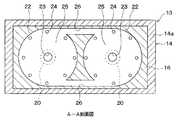
2本の第3管状部11cの上端部同士は、薄型直方体状のブロック体13によって連結されている。このブロック体13は容器11の一部を構成しており、熱伝導率に優れた銅又はアルミニウム等によって成形されている。本例では、成形上の都合により、ブロック体13を矩形平板状の第1〜第3分割体14〜16に分割して成形している。そして、これら第1〜第3分割体14〜16を積層した状態でネジ等の締結手段によって一体に締結するようになっている。 The upper ends of the two third
第1〜第3分割体14〜16のうち第3管状部11cの上端部に隣接配置される第1分割体14の外周部には、第2、第3分割体15、16の外周端面に当接する枠状部14aが形成されている。 Among the first to third divided
ブロック体13の内部には、2本の第3管状部11cとそれぞれ連通する2つの中空部が形成されており、この中空部によって加熱部17が構成されている。加熱部17は、外部熱源により作動媒体12を加熱して作動媒体12の蒸気を発生させる役割を果たすものであり、詳細は後述する。 Two hollow portions communicating with the two third
2本の第3管状部11cの長手方向の中間部18はそれぞれ、熱伝導率に優れた銅又はアルミニウムによって形成されており、この中間部18内空間によって冷却部19が構成されている。冷却部19は、加熱部17で発生した作動媒体12の蒸気を冷却して液化させる役割を果たすものである。 The
本例では、第3管状部11cの中間部18に冷却水が循環することによって、冷却部19にて作動媒体12の蒸気が冷却されるようになっている。冷却水の循環回路中には放熱器(図示せず)が配置されており、冷却水が作動媒体12の蒸気から奪った熱を放熱器によって大気中に放熱するようになっている。 In this example, the cooling water circulates in the
なお、容器11のうちブロック体13及び第3管状部11cの中間部18以外の部位は、断熱性に優れたステンレスによって成形されている。 In addition, parts other than the
一方、容器11のうち第3管状部11cの上端部には、作動媒体12の液体部分から圧力を受けて変位するピストン3がシリンダ部3aに摺動可能に配置されている。なお、ピストン3は可動子2のシャフト2aに連結されており、可動子2を挟んでピストン3と反対側には、可動子2をピストン3側に押圧する弾性力を発生させる弾性手段をなすバネ4が設けられている。 On the other hand, a piston 3 that is displaced by receiving pressure from the liquid portion of the working
次に、加熱部17の詳細について説明する。本例における2つの加熱部17は、高温ガスによって加熱されるようになっており、それぞれの内部に第1、第2通路部20、21を有している。 Next, details of the
この第1、第2通路部20、21のうち冷却部19に近い側に配置される第1通路部20は、第3管状部11cと同軸上の円筒形状を有している。また、第1、第2通路部20、21のうち冷却部19から離れた側に配置される第2通路部21は、第1通路部20のうち冷却部19と反対側の端部(図1の上端部)から第1通路部20の径方向外側に環状に突き出す形状を有している。 The 1st channel |
これにより、第1通路部20の上端面20aは、作動媒体12の蒸気の体積が減少して作動媒体12の液体部分が冷却部19側(図1の下方側)から加熱部17側(図1の上方側)に向かって変位したときに作動媒体12の液体部分が衝突する衝突面を構成する。 As a result, the
本例では、第2通路部21の厚み寸法(図1の上下方向寸法)tは、第1通路部20の内径Dよりも小さく設定されている(t<D)。また、第2通路部21の厚み寸法tを熱浸透深さσ以下(t≦σ)に設定することによって、第2通路部21において作動媒体12を良好に加熱できるようにしている。 In this example, the thickness dimension (vertical direction dimension in FIG. 1) t of the
ここで、熱浸透深さσは、第2通路部21内の作動媒体12が周期的に温度変化する場合に、その温度変化が何処まで伝わるかを表す指標である。具体的には、熱浸透深さσは第2通路部21の厚み方向のエントロピー変動の分布を熱拡散率a(m/s)と角振動数ω(rad/s)で決定する指標であり、次の数式(1)で表される。 Here, the heat penetration depth σ is an index representing how far the temperature change is transmitted when the temperature of the working
σ=√(2・a/ω)…(1)
なお、熱拡散率aは、作動媒体12の熱伝導率を作動媒体12の比熱と密度で除した値である。σ = √ (2 · a / ω) (1)
The thermal diffusivity a is a value obtained by dividing the thermal conductivity of the working
ブロック体13の内部であって加熱部17よりも上方側には、加熱部17で発生した作動媒体12の蒸気を溜めるための空間である蒸気溜め部22が形成されており、この蒸気溜め部22と加熱部17は第1、第2蒸気通路23、24によって連通している。なお、第1蒸気通路23は、本発明における通路に該当するものである。 Inside the
本例では、蒸気溜め部22は、加熱部17のうち第2通路部21と所定間隔だけ離れて対向する円板状の空間で構成されており、第2通路部21と同軸上に配置されている。また、蒸気溜め部22には、所定体積の付加媒体の気体25が封入されている。付加媒体としては、外燃機関の作動条件下では気体の状態を維持する媒体を選定することができる。気体25は、例えば、取り扱いのしやすい空気であってもよいし、作動媒体12の純粋な蒸気でもよい。 In this example, the
第1蒸気通路23は、加熱部17のうち第1通路部20の上端面20aに配置された1つの円形穴で構成されており、加熱部17のうち上端面20aの形成部位と蒸気溜め部22の中心部とを連通する。第1蒸気通路23の内径d1は、第1通路部20の内径D未満に設定されている(d1<D)。本例では、第1蒸気通路23を第1通路部20と同軸上に配置している。 The
第2蒸気通路24は、加熱部17のうち第2通路部21の外周部と蒸気溜め部22の外周部とを連通する複数個の円形穴である。本例では、複数個の第2蒸気通路24を第2通路部21及び蒸気溜め部22の円周方向に等間隔に配置している。 The
本例では、作動媒体12の蒸気の体積が最も減少して、作動媒体12の液面が最も上昇した場合においても、蒸気溜め部22に作動媒体12の液体部分が進入しないように、容器11に対する作動媒体12の封入体積が設定されている。 In this example, the
より具体的には、作動媒体12の液面は、最も上昇したときに第1通路部20の上端面20aまで到達するようになっている。このため、加熱部17内において作動媒体12の蒸気が発生すると、作動媒体12の蒸気が第1、第2蒸気通路23、24を通じて蒸気溜め部22に流入することができる。 More specifically, the liquid level of the working
蒸気溜め部22は加熱部17と同様にブロック体13の内部に形成されているので、蒸気溜め部22内の気体25は作動媒体12の蒸気の温度とほぼ同じ温度に加熱される。これにより、作動媒体12の蒸気が蒸気溜め部22に進入したときに、作動媒体12の蒸気が蒸気溜め部22内で冷やされて液化してしまうことを回避するようになっている。 Since the
2つの蒸気溜め部22、すなわち一方の加熱部17に対応する蒸気溜め部22と他方の加熱部17に対応する蒸気溜め部22同士は、ブロック体13内部に形成された連通路26によって連通している。本例では、2つの連通路26を、ブロック体13の長辺(図2の左右方向に延びる辺)と平行に、かつ、蒸気溜め部22の円板形状と接するように形成している。 The two
次に、本実施形態の加熱部17、蒸気溜め部22、第1、第2蒸気通路23、24及び連通路26の成形方法について簡単に説明すると、ブロック体13の第1〜第3分割体14〜16に、加熱部17、蒸気溜め部22、第1、第2蒸気通路23、24及び連通路26に対応する形状を切削加工したのちに、第1〜第3分割体14〜16を一体に締結することによって、ブロック体13の内部に加熱部17、蒸気溜め部22、第1、第2蒸気通路23、24及び連通路26を成形することができる。 Next, a brief description will be given of a method of forming the
より具体的には、第1分割体14には、加熱部17の第1通路部20に対応する貫通穴を加工する。第2分割体15には、加熱部17の第2通路部21に対応する円形の窪み形状と、第1、第2蒸気通路23、24に対応する貫通穴とを加工する。第3分割体16には、蒸気溜め部22に対応する円形の窪み形状と、連通路26に対応する溝形状を加工したのちに、第1〜第3分割体14〜16を一体に締結する。 More specifically, a through hole corresponding to the
次に、上記構成における作動を簡単に説明する。まず加熱部17内の作動媒体(水)12が加熱されて気化すると、蒸気溜め部22内及び加熱部17内に高温・高圧の作動媒体12の蒸気が蓄積されて、第3管状部11c内の作動媒体12の液面を押し下げる。すると、作動媒体12の液体部分が第1管状部11a側に変位して、発電機1側のピストン3を押し上げる。 Next, the operation in the above configuration will be briefly described. First, when the working medium (water) 12 in the
次に、第3管状部11c内の作動媒体12の液面が冷却部19まで下がり、冷却部19内に作動媒体12の蒸気が進入すると、作動媒体12の蒸気が冷却部19により冷却されて液化する。このため、作動媒体12の液面を押し下げる力が消滅し、作動媒体12の液面が上昇し、作動媒体12の液体部分も上昇する。この結果、作動媒体12の蒸気の膨張によって一旦押し上げられた発電機1側のピストン3は下降する。 Next, when the liquid level of the working
このような動作が繰り返し実行されることによって、容器11内の作動媒体12の液体部分が周期的に変位(いわゆる自励振動)して、発電機1の可動子2を周期的に上下動させる。 By repeatedly executing such an operation, the liquid portion of the working
つまり、作動媒体12の蒸気の発生と液化によって作動媒体12が体積変動し、作動媒体12の体積変動によって生じる作動媒体12の液体部分の変位を機械的エネルギに変換して出力することができる。なお、ここでいう「作動媒体12の体積」とは、作動媒体12の液体部分の体積と作動媒体12の蒸気の体積の合計のことを意味している。 That is, the volume of the working
本実施形態では、第3管状部11cを2本の管状部で構成し、2本の第3管状部11cに対応して加熱部17及び冷却部19を2個ずつ形成しているので、加熱部17及び冷却部19の伝熱面積を増大させることができる。これにより、作動媒体12の加熱性能及び冷却性能を向上させて、外燃機関の出力を向上させることができる。 In the present embodiment, the third
また、2つの加熱部17同士を第1、第2蒸気通路23、24、蒸気溜め部22及び連通路26を介して連通させているので、2つの加熱部17間、換言すれば2つの第3管状部11c間で作動媒体12の蒸気発生タイミングがずれても、2つの第3管状部11cの内部圧力を同一圧力にすることができるので、2つの第3管状部11c間で圧力差が生じることを回避できる。 In addition, since the two
このため、2つの第3管状部11c間で作動媒体12の蒸気発生タイミングがずれたときに、作動媒体12の液体部分の一部が蒸気発生タイミングの速い第3管状部11c側から蒸気発生タイミングの遅い第3管状部11c側へ向かって変位してしまうことを防止できるので、外燃機関の効率の低下を抑制できる。 For this reason, when the vapor generation timing of the working
ここで、本実施形態では、2つの加熱部17同士を直接連通させず、第1、第2蒸気通路23、24、蒸気溜め部22及び連通路26を介して連通させている。このため、2つの第3管状部11c間で作動媒体12の蒸気発生タイミングがずれると、蒸気発生タイミングの速い第3管状部11c側の蒸気溜め部22から蒸気発生タイミングの遅い第3管状部11c側の蒸気溜め部22へと作動媒体12の蒸気が移動する。 Here, in the present embodiment, the two
すると、蒸気発生タイミングの速い第3管状部11c側の蒸気溜め部22から蒸気発生タイミングの遅い第3管状部11c側の蒸気溜め部22へと移動した作動媒体12の蒸気は、蒸気発生タイミングの遅い第3管状部11c側の蒸気溜め部22内に封入された気体25と混在する。 Then, the steam of the working
換言すれば、蒸気発生タイミングの速い第3管状部11c側の蒸気溜め部22から蒸気発生タイミングの遅い第3管状部11c側の蒸気溜め部22へと移動した作動媒体12の蒸気が、蒸気発生タイミングの遅い第3管状部11c側の蒸気溜め部22内において作動媒体12の液体部分と混在して気泡状になることを抑制できる。 In other words, the steam of the working
このため、作動媒体12の蒸気が作動媒体12の液体部分によって冷やされて液化してしまうことを抑制できるので、上記従来技術のように作動媒体の蒸気が液化する分だけ作動媒体の変位量が減少して外燃機関の出力が低下してしまうことを抑制できる。つまり、上記従来技術と比較して、外燃機関の出力を向上できる。 For this reason, since it can suppress that the vapor | steam of the working
なお、本例では、2つの加熱部17が水平方向に配置され、2つの蒸気溜め部22が2つの加熱部17の上方に配置され、連通路26が2つの蒸気溜め部22同士の間において水平方向に延びているので、2つの蒸気溜め部22同士の間の空間を利用して2つの蒸気溜め部22同士を連通させることができる。 In this example, the two
これにより、2つの蒸気溜め部22同士を連通させることに伴って外燃機関の体格が大型化してしまうことを抑制できる。 Thereby, it can suppress that the physique of an external combustion engine will enlarge in connection with communicating the two
ところで、本実施形態では、加熱部17を、第3管状部11cと同軸状の第1通路部20と、第1通路部20の径方向外側に環状に突き出す第2通路部21とで構成している。 By the way, in this embodiment, the
このため、作動媒体12の蒸気が冷却部19により冷却されて液化されて作動媒体12の液面が上昇すると、まず作動媒体12の液体部分が加熱部17のうち第1通路部20に真っ直ぐに進入し、第1通路部20の上端面20aに衝突したのちに、変位方向を水平方向に変化させて第2通路部21に進入する。 For this reason, when the vapor of the working
このように、作動媒体12の液体部分が第1通路部20の上端面20aに衝突すると、作動媒体12の液体部分が撹拌されて乱流が生じる。この結果、加熱部17内に形成される温度境界層を破壊することができるので、加熱部17から作動媒体12への熱伝達率を向上できる。 As described above, when the liquid portion of the working
また、本実施形態では、第2通路部21が水平方向に延びているので、撹拌された作動媒体12の液体部分が重力に逆らうことなく第2通路部21に進入できる。このため、作動媒体12の液体部分が撹拌された状態を維持しつつ第2通路部21に進入することが容易になるので、加熱部17から作動媒体12への熱伝達率をより効果的に向上できる。 In the present embodiment, since the
ここで、加熱部17と蒸気溜め部22とを第2蒸気通路24のみによって連通させる場合、つまり、第1蒸気通路23を設けない場合には、第2蒸気通路24が第2通路部21の外周部に配置されている関係上、第1通路部20の上端面20a近傍で発生した作動媒体12の蒸気は第2通路部21を通過しなければ蒸気溜め部22に溜まることができない。つまり、第1通路部20の上端面20a近傍で発生した作動媒体12の蒸気を蒸気溜め部22にスムーズに導くことができない。 Here, when the
このため、作動媒体12の蒸気が第2通路部21を通過する際に第2通路部21内の作動媒体12の液体部分と混在して気泡状になり、作動媒体12の液体部分によって冷やされて液化してしまうので、その分、作動媒体12の変位量が減少して外燃機関の出力が低下してしまう。 For this reason, when the vapor of the working
この点に鑑み、本実施形態では、加熱部17と蒸気溜め部22とを第2蒸気通路24のみならず、第1通路部20の上端面20aに配置した第1蒸気通路23によっても連通させているので、図1の矢印bのように第1通路部20の上端面20a近傍で発生した作動媒体12の蒸気を第1蒸気通路23を通じて速やかに蒸気溜め部22へと逃がすことができる。 In view of this point, in the present embodiment, the
このため、作動媒体12の蒸気が作動媒体12の液体部分と混在して気泡状になってしまうことを抑制できるので、外燃機関の出力を向上できる。 For this reason, since it can suppress that the vapor | steam of the working
さらに、本実施形態では、第1蒸気通路23を第1通路部20と同軸上に配置しており、第1蒸気通路23が第1通路部20の延びる方向と平行になるので、上端面20aへの作動媒体12の衝突方向と第1蒸気通路23の延びる方向とを同一方向にすることができる。 Further, in the present embodiment, the
このため、第1通路部20の上端面20a近傍で発生した作動媒体12の蒸気を蒸気通路23を通じてより速やかに蒸気溜め部22へと逃がすことができる。この結果、衝突面20aで発生した作動媒体12の蒸気が作動媒体12の液体部分と混在して気泡状になってしまうことをより抑制できるので、外燃機関の出力をより向上することができる。 For this reason, the steam of the working
なお、本実施形態では、第1蒸気通路23の内径d1を第1通路部20の内径D未満に設定しているので(d1<D)、第1通路部20の上端面に第1蒸気通路23を設けても、作動媒体12を第1通路部20の上端面に良好に衝突させることができる。 In the present embodiment, since the inner diameter d1 of the
(第2実施形態)
上記第1実施形態では、第1蒸気通路23を1つの円形穴で構成しているが、本第2実施形態では、図3に示すように、第1蒸気通路23を多数個の細孔で構成している。(Second Embodiment)
In the said 1st Embodiment, although the 1st vapor | steam channel |
この多数個の細孔の内径d2は、第2通路部21の厚み寸法tより大きく設定されている(d2>t)。これにより、多数個の細孔における流路抵抗を第2通路部21における流路抵抗よりも小さくできるので、第1通路部20の上端面近傍で発生した作動媒体12の蒸気は、第2通路部21側よりも第1蒸気通路23側に導かれるようになる。 The inner diameter d2 of the multiple pores is set to be larger than the thickness dimension t of the second passage portion 21 (d2> t). Thereby, since the flow resistance in many pores can be made smaller than the flow resistance in the
この結果、第1通路部20の上端面近傍で発生した作動媒体12の蒸気を第1蒸気通路23を通じて速やかに蒸気溜め部22へと逃がすことができるので、上記第1実施形態と同様の効果を発揮できる。 As a result, the steam of the working
(第3実施形態)
本第3実施形態は、上記第1実施形態に対して、蒸気溜め部22の形状を変更している。図4(a)は本実施形態における加熱部17の縦断面図を示し、図4(b)は図4(a)のC−C断面図を示している。(Third embodiment)
In the third embodiment, the shape of the
本実施形態では、蒸気溜め部22を、第1蒸気通路23の上方にブロック体13の長辺方向と平行に延びる帯状に形成された帯状蒸気溜め部22aと、加熱部17の第2通路部21の外周側に環状に形成された環状蒸気溜め部22bとで構成している。 In the present embodiment, the
帯状蒸気溜め部22aは第1蒸気通路23を介して加熱部17と連通しており、帯状蒸気溜め部22aは、2つの第1通路部20の中心同士を結ぶ方向(図4(b)の左右方向)と平行に配置されている。 The strip-shaped
本実施形態では、第2蒸気通路24を帯状蒸気溜め部22aと環状蒸気溜め部22bとの間に2つ配置し、第2蒸気通路24によって帯状蒸気溜め部22aと環状蒸気溜め部22bとを連通させている。 In the present embodiment, two
また、本実施形態では、連通路26が2つの帯状蒸気溜め部22aの隣り合う端部同士を連通するように1つのみ配置されている。これにより、2つの帯状蒸気溜め部22a及び連通路26は、全体として1つの帯状になっている。 Further, in the present embodiment, only one
本実施形態においても、上記第1実施形態と同様の効果を発揮できる。 Also in this embodiment, the same effect as the first embodiment can be exhibited.
さらに、本実施形態によると、帯状蒸気溜め部22aは上方から見たときに第2通路部21の一部のみと重合している。このため、上記各実施形態のように蒸気溜め部22が上方から見たときに第2通路部21の全体と重合する場合と比較して、熱源(高温ガス)のもつ熱を上方から第2通路部21へと伝達しやすい。このため、第2通路部21にて作動媒体12を効果的に加熱できる。 Furthermore, according to the present embodiment, the belt-shaped
また、本実施形態では、2つの帯状蒸気溜め部22a及び連通路26は、全体として1つの帯状になっているので、ブロック体13を第1、第2分割体21、22の2分割によって成形することができる。 Further, in the present embodiment, the two strip-shaped
より具体的には、第2分割体15にその長辺方向と平行に延びる矩形貫通穴を成形することによって2つの帯状蒸気溜め部22a及び連通路26を構成することができ、また、第2分割体15に、環状蒸気溜め部22bに対応する環状の窪み形状と、第2蒸気通路24に対応する穴を加工すれば、ブロック体13内部に加熱部17及び蒸気溜め部22等を成形することができる。 More specifically, by forming a rectangular through hole extending in parallel with the long side direction in the second divided
このため、ブロック体13の構造を簡素化でき、コストを低減できる。 For this reason, the structure of the
(第4実施形態)
上記各実施形態では、第2通路部21を第1通路部20の径方向外側に突き出す環状に形成し、蒸気溜め部22を第1通路部20と対向する円板状に形成しているが、本第4実施形態では、図5に示すように、第2通路部21を第1通路部20の軸方向と直交する方向に延びる帯状に形成し、蒸気溜め部22を第1通路部20と対向する帯状に形成している。(Fourth embodiment)
In each of the above embodiments, the
本実施形態においても、第2通路部21の厚み寸法tを、第1通路部20の内径Dよりも小さく、かつ、熱浸透深さσ以下に設定し(t<Dかつt≦σ)、これにより、第2通路部21において作動媒体12を良好に加熱できるようにしている。 Also in the present embodiment, the thickness dimension t of the
第2蒸気通路24は、第2通路部21のうち第1通路部20と反対側の端部と蒸気溜め部22のうち第1通路部20と反対側の端部とを連通するように、1つのみ形成されている。 The
連通路26は、2つの蒸気溜め部22のうち隣り合う端部同士を連通するように、1つのみ配置されている。 Only one
本実施形態においても、上記第1実施形態と同様の効果を発揮できる。 Also in this embodiment, the same effect as the first embodiment can be exhibited.
(他の実施形態)
(1)上記各実施形態では、第1通路部20の軸方向と第2通路部21の突き出す方向とが直交しているが、これに限定されるものではなく、第1通路部20の軸方向と第2通路部21の突き出す方向とが交差するようにすればよい。(Other embodiments)
(1) In each of the above embodiments, the axial direction of the
(2)上記各実施形態では、第1通路部20を円筒面によって構成しているが、これに限定されるものではなく、例えば、角筒状の面によって構成してもよい。 (2) In each of the above embodiments, the
(3)上記各実施形態における第2通路部21の形状(環状、帯状)は一例を示したものであり、種々変形が可能である。例えば、第1通路部20から多数本放射状に突き出す形状にしてもよい。また、第1通路部20から断面円形状に突き出す形状にしてもよい。
(3) The shape (annular shape, strip shape) of the
(4)上記各実施形態では、2本の第3管状部11cを第2管状部11bから上方に向かって延びるように形成し、加熱部17を冷却部19よりも上方に配置しているが、2本の第3管状部11cを第2管状部11bから下方に向かって延びるように形成し、加熱部17を冷却部19よりも下方に配置してもよい。 (4) In each of the above embodiments, the two third
(5)上記各実施形態では、第3管状部11cを2本配置し、2本の第3管状部11cに対応して加熱部17及び冷却部19を2つずつ形成しているが、第3管状部11cを3本以上配置し、3本以上の第3管状部11cに対応して加熱部17及び冷却部19を3つ以上ずつ形成するようにしてもよい。 (5) In each of the above embodiments, two third
(6)上記各実施形態では、冷却部19を第3管状部11cの中間部18に形成しているが、冷却部19を第2管状部11bに形成してもよい。 (6) In each of the above embodiments, the cooling
(7)上記各実施形態では、加熱部17が高温ガスによって加熱されるようになっているが、加熱部17を電気ヒータで加熱するようにしてもよい。 (7) In each of the above embodiments, the
(8)上記各実施形態は、本発明を発電装置の駆動源に適用した例を示しているが、これに限定されるものではなく、本発明の外燃機関を発電装置以外の駆動源に適用できることはもちろんである。 (8) Although each said embodiment has shown the example which applied this invention to the drive source of the electric power generating apparatus, it is not limited to this, The external combustion engine of this invention is used as drive sources other than an electric power generating apparatus. Of course, it can be applied.
11…容器、11c…第3管状部(複数本の管状部)、12…作動媒体、
13…ブロック体、17…加熱部、19…冷却部、22…蒸気溜め部、
23…第1蒸気通路(通路)、26…連通路。DESCRIPTION OF
13 ... Block body, 17 ... Heating part, 19 ... Cooling part, 22 ... Steam reservoir part,
23 ... 1st steam passage (passage), 26 ... Communication passage.
Claims (6)
Translated fromJapanese前記容器(11)には、前記作動媒体(12)の一部を加熱して前記作動媒体(12)の蒸気を発生させる加熱部(17)と、前記蒸気を冷却して液化させる冷却部(19)とが形成され、
前記蒸気の発生と液化によって前記作動媒体(12)が体積変動し、前記作動媒体(12)の体積変動によって生じる前記作動媒体(12)の液体部分の変位を機械的エネルギに変換して出力する外燃機関であって、
前記容器(11)のうち少なくとも前記加熱部(17)と連通する部位が複数本の管状部(11c)に分岐し、
前記加熱部(17)は、前記複数本の管状部(11c)とそれぞれ連通するように、前記複数本の管状部(11c)と同数の複数個形成され、
前記作動媒体(12)の蒸気を溜める蒸気溜め部(22)が、前記複数個の加熱部(17)とそれぞれ連通するように、前記複数個の加熱部(17)と同数の複数個形成され、
前記複数個の蒸気溜め部(22)同士が連通し、
前記加熱部(17)には、前記蒸気の体積が減少して前記作動媒体(12)の液体部分が前記冷却部(19)側から前記加熱部(17)側に向かって変位したときに前記作動媒体(12)の液体部分が衝突する衝突面(20a)が形成され、
前記蒸気溜め部(22)が前記加熱部(17)のうち前記衝突面(20a)の形成部位と連通していることを特徴とする外燃機関。A working medium (12) comprising a container (11) enclosed in a liquid state so as to be flowable;
The container (11) includes a heating unit (17) that heats a part of the working medium (12) to generate vapor of the working medium (12), and a cooling unit that cools and liquefies the vapor ( 19) and
The working medium (12) fluctuates in volume due to the generation and liquefaction of the vapor, and the displacement of the liquid part of the working medium (12) caused by the fluctuating volume of the working medium (12) is converted into mechanical energy and output. An external combustion engine,
Of the container (11), at least a portion communicating with the heating part (17) branches into a plurality of tubular parts (11c),
The heating section (17) is formed in thesame number as the pluralityof tubular sections (11c) so as to communicate with the plurality of tubular sections (11c), respectively.
A plurality of steam reservoirs (22) for storing steam of the working medium (12) are formed in thesame number as the pluralityof heating units (17) so as to communicate with the plurality of heating units (17), respectively. ,
The plurality of vapor reservoirs (22) communicate with each other,
In the heating part (17), when the volume of the vapor decreases and the liquid part of the working medium (12) is displaced from the cooling part (19) side toward the heating part (17) side, A collision surface (20a) is formed on which the liquid portion of the working medium (12) collides,
The external combustion engine characterized in that thesteam reservoir (22) communicates witha formation site of the collision surface (20a) in the heating unit (17) .
前記複数個の蒸気溜め部(22)が前記複数個の加熱部(17)の上方に配置され、
前記複数個の蒸気溜め部(22)同士を連通する連通路(26)が、前記複数個の蒸気溜め部(22)同士の間において水平方向に延びていることを特徴とする請求項1または2に記載の外燃機関。The plurality of heating units (17) are arranged in a horizontal direction,
The plurality of vapor reservoirs (22) are disposed above the plurality of heating units (17),
The communication passage (26) for communicating the plurality of vapor reservoirs (22) extends in a horizontal direction between the plurality of vapor reservoirs (22). 2. An external combustion engine described in 2.
前記衝突面(20a)が、前記第1通路部(20)のうち前記冷却部(19)と反対側の端部に形成され、
前記蒸気溜め部(22)は、前記第1通路部(20)に対して前記冷却部(19)と反対側に配置され、
前記加熱部(17)と前記蒸気溜め部(22)とを連通する通路(23)が、前記衝突面(20a)と前記蒸気溜め部(22)との間において、前記第1通路部(20)が延びる方向と平行に延びていることを特徴とする請求項1ないし3のいずれか1つに記載の外燃機関。The heating section (17) extends toward the cooling section (19), and the end of the first passage section (20) opposite to the cooling section (19). A second passage portion (21) extending in a direction intersecting with a direction in which the first passage portion (20) extends,
The collision surface (20a) is formed at an end of the first passage portion (20) opposite to the cooling portion (19),
The steam reservoir (22) is disposed on the opposite side of the cooling part (19) with respect to the first passage part (20),
A passage (23) communicating the heating unit (17) and the vapor reservoir (22) is provided between the collision surface (20a) and the vapor reservoir (22). The external combustion engine according toany one of claims1 to 3, wherein the external combustion engine extends in parallel with an extending direction.
Priority Applications (2)
| Application Number | Priority Date | Filing Date | Title |
|---|---|---|---|
| JP2007020631AJP4306733B2 (en) | 2007-01-31 | 2007-01-31 | External combustion engine |
| US11/973,364US7574861B2 (en) | 2007-01-31 | 2007-10-05 | External combustion engine |
Applications Claiming Priority (1)
| Application Number | Priority Date | Filing Date | Title |
|---|---|---|---|
| JP2007020631AJP4306733B2 (en) | 2007-01-31 | 2007-01-31 | External combustion engine |
Publications (2)
| Publication Number | Publication Date |
|---|---|
| JP2008184993A JP2008184993A (en) | 2008-08-14 |
| JP4306733B2true JP4306733B2 (en) | 2009-08-05 |
Family
ID=39666396
Family Applications (1)
| Application Number | Title | Priority Date | Filing Date |
|---|---|---|---|
| JP2007020631AExpired - Fee RelatedJP4306733B2 (en) | 2007-01-31 | 2007-01-31 | External combustion engine |
Country Status (2)
| Country | Link |
|---|---|
| US (1) | US7574861B2 (en) |
| JP (1) | JP4306733B2 (en) |
Families Citing this family (6)
| Publication number | Priority date | Publication date | Assignee | Title |
|---|---|---|---|---|
| US20070238455A1 (en)* | 2006-04-07 | 2007-10-11 | Yinjun Zhu | Mobile based area event handling when currently visited network doe not cover area |
| JP4277909B2 (en)* | 2007-02-07 | 2009-06-10 | 株式会社デンソー | External combustion engine |
| JP4525763B2 (en)* | 2008-02-07 | 2010-08-18 | 株式会社デンソー | External combustion engine |
| JP4992917B2 (en)* | 2009-01-28 | 2012-08-08 | 株式会社デンソー | External combustion engine |
| JP5109992B2 (en)* | 2009-01-30 | 2012-12-26 | 株式会社デンソー | External combustion engine |
| KR101741536B1 (en)* | 2016-03-30 | 2017-05-30 | 제주대학교 산학협력단 | A fluidyne stirling engine for electric power production |
Family Cites Families (5)
| Publication number | Priority date | Publication date | Assignee | Title |
|---|---|---|---|---|
| US4195481A (en)* | 1975-06-09 | 1980-04-01 | Gregory Alvin L | Power plant |
| CH660779A5 (en)* | 1983-06-20 | 1987-06-15 | Sulzer Ag | REFRIGERATOR OR HEAT PUMP WITH THERMOACOUSTIC DRIVE AND WORK PARTS. |
| DE102005022846B4 (en) | 2004-05-19 | 2015-12-17 | Denso Corporation | steam engine |
| JP4363255B2 (en) | 2004-05-19 | 2009-11-11 | 株式会社デンソー | Steam engine |
| JP4264040B2 (en) | 2004-09-01 | 2009-05-13 | アルプス電気株式会社 | Antenna device |
- 2007
- 2007-01-31JPJP2007020631Apatent/JP4306733B2/ennot_activeExpired - Fee Related
- 2007-10-05USUS11/973,364patent/US7574861B2/ennot_activeExpired - Fee Related
Also Published As
| Publication number | Publication date |
|---|---|
| US7574861B2 (en) | 2009-08-18 |
| JP2008184993A (en) | 2008-08-14 |
| US20080178595A1 (en) | 2008-07-31 |
Similar Documents
| Publication | Publication Date | Title |
|---|---|---|
| JP4706520B2 (en) | External combustion engine | |
| JP4306733B2 (en) | External combustion engine | |
| US7644582B2 (en) | External combustion engine | |
| JP2005522664A5 (en) | ||
| WO2016151805A1 (en) | Cooler, power conversion device, and cooling system | |
| KR20130105667A (en) | Cooler and refrigeration device provided with same | |
| JP2013160420A (en) | Self-excited vibration heat pipe | |
| JP2013242111A (en) | Loop type heat pipe and electronic apparatus | |
| JP5673589B2 (en) | Heat engine | |
| JP2005330885A (en) | Steam engine | |
| WO2020225981A1 (en) | Self-excited vibration heat pipe cooling device, and railway vehicle on which cooling device is mounted | |
| JP2010025411A (en) | Heat exchanger and pulse tube refrigerating machine | |
| JP5035109B2 (en) | External combustion engine | |
| JP4993019B2 (en) | External combustion engine | |
| US8020380B2 (en) | External combustion engine | |
| JP4251222B2 (en) | External combustion engine | |
| WO2013110938A2 (en) | A generator for an absorption chiller and an absorption chiller comprising such a generator | |
| JP5768687B2 (en) | Thermoacoustic refrigeration equipment | |
| JP2005330884A (en) | Steam engine | |
| JP2016200293A (en) | Cooler | |
| JP6390566B2 (en) | Cooler | |
| JP2015105775A (en) | Heat exchange module for thermoacoustic engine, and thermoacoustic engine | |
| JP2012087627A (en) | Heat engine | |
| JP2016145667A (en) | Cooler | |
| JP2009167915A (en) | External combustion engine |
Legal Events
| Date | Code | Title | Description |
|---|---|---|---|
| A621 | Written request for application examination | Free format text:JAPANESE INTERMEDIATE CODE: A621 Effective date:20080611 | |
| A131 | Notification of reasons for refusal | Free format text:JAPANESE INTERMEDIATE CODE: A131 Effective date:20090203 | |
| A521 | Written amendment | Free format text:JAPANESE INTERMEDIATE CODE: A523 Effective date:20090316 | |
| TRDD | Decision of grant or rejection written | ||
| A01 | Written decision to grant a patent or to grant a registration (utility model) | Free format text:JAPANESE INTERMEDIATE CODE: A01 Effective date:20090414 | |
| A01 | Written decision to grant a patent or to grant a registration (utility model) | Free format text:JAPANESE INTERMEDIATE CODE: A01 | |
| A61 | First payment of annual fees (during grant procedure) | Free format text:JAPANESE INTERMEDIATE CODE: A61 Effective date:20090427 | |
| R150 | Certificate of patent or registration of utility model | Free format text:JAPANESE INTERMEDIATE CODE: R150 | |
| FPAY | Renewal fee payment (event date is renewal date of database) | Free format text:PAYMENT UNTIL: 20120515 Year of fee payment:3 | |
| FPAY | Renewal fee payment (event date is renewal date of database) | Free format text:PAYMENT UNTIL: 20120515 Year of fee payment:3 | |
| FPAY | Renewal fee payment (event date is renewal date of database) | Free format text:PAYMENT UNTIL: 20130515 Year of fee payment:4 | |
| FPAY | Renewal fee payment (event date is renewal date of database) | Free format text:PAYMENT UNTIL: 20140515 Year of fee payment:5 | |
| R250 | Receipt of annual fees | Free format text:JAPANESE INTERMEDIATE CODE: R250 | |
| LAPS | Cancellation because of no payment of annual fees |