JP4301849B2 - Information processing method and its execution system, its processing program, disaster recovery method and system, storage device for executing the processing, and its control processing method - Google Patents
Information processing method and its execution system, its processing program, disaster recovery method and system, storage device for executing the processing, and its control processing methodDownload PDFInfo
- Publication number
- JP4301849B2 JP4301849B2JP2003096725AJP2003096725AJP4301849B2JP 4301849 B2JP4301849 B2JP 4301849B2JP 2003096725 AJP2003096725 AJP 2003096725AJP 2003096725 AJP2003096725 AJP 2003096725AJP 4301849 B2JP4301849 B2JP 4301849B2
- Authority
- JP
- Japan
- Prior art keywords
- database
- data
- storage subsystem
- processing
- log information
- Prior art date
- Legal status (The legal status is an assumption and is not a legal conclusion. Google has not performed a legal analysis and makes no representation as to the accuracy of the status listed.)
- Expired - Fee Related
Links
Images


Classifications
- G—PHYSICS
- G06—COMPUTING OR CALCULATING; COUNTING
- G06F—ELECTRIC DIGITAL DATA PROCESSING
- G06F11/00—Error detection; Error correction; Monitoring
- G06F11/07—Responding to the occurrence of a fault, e.g. fault tolerance
- G06F11/16—Error detection or correction of the data by redundancy in hardware
- G06F11/20—Error detection or correction of the data by redundancy in hardware using active fault-masking, e.g. by switching out faulty elements or by switching in spare elements
- G06F11/2053—Error detection or correction of the data by redundancy in hardware using active fault-masking, e.g. by switching out faulty elements or by switching in spare elements where persistent mass storage functionality or persistent mass storage control functionality is redundant
- G06F11/2056—Error detection or correction of the data by redundancy in hardware using active fault-masking, e.g. by switching out faulty elements or by switching in spare elements where persistent mass storage functionality or persistent mass storage control functionality is redundant by mirroring
- G06F11/2071—Error detection or correction of the data by redundancy in hardware using active fault-masking, e.g. by switching out faulty elements or by switching in spare elements where persistent mass storage functionality or persistent mass storage control functionality is redundant by mirroring using a plurality of controllers
- G06F11/2074—Asynchronous techniques
- G—PHYSICS
- G06—COMPUTING OR CALCULATING; COUNTING
- G06F—ELECTRIC DIGITAL DATA PROCESSING
- G06F11/00—Error detection; Error correction; Monitoring
- G06F11/07—Responding to the occurrence of a fault, e.g. fault tolerance
- G06F11/16—Error detection or correction of the data by redundancy in hardware
- G06F11/20—Error detection or correction of the data by redundancy in hardware using active fault-masking, e.g. by switching out faulty elements or by switching in spare elements
- G06F11/2053—Error detection or correction of the data by redundancy in hardware using active fault-masking, e.g. by switching out faulty elements or by switching in spare elements where persistent mass storage functionality or persistent mass storage control functionality is redundant
- G06F11/2056—Error detection or correction of the data by redundancy in hardware using active fault-masking, e.g. by switching out faulty elements or by switching in spare elements where persistent mass storage functionality or persistent mass storage control functionality is redundant by mirroring
- G06F11/2071—Error detection or correction of the data by redundancy in hardware using active fault-masking, e.g. by switching out faulty elements or by switching in spare elements where persistent mass storage functionality or persistent mass storage control functionality is redundant by mirroring using a plurality of controllers
- G06F11/2076—Synchronous techniques
- Y—GENERAL TAGGING OF NEW TECHNOLOGICAL DEVELOPMENTS; GENERAL TAGGING OF CROSS-SECTIONAL TECHNOLOGIES SPANNING OVER SEVERAL SECTIONS OF THE IPC; TECHNICAL SUBJECTS COVERED BY FORMER USPC CROSS-REFERENCE ART COLLECTIONS [XRACs] AND DIGESTS
- Y10—TECHNICAL SUBJECTS COVERED BY FORMER USPC
- Y10S—TECHNICAL SUBJECTS COVERED BY FORMER USPC CROSS-REFERENCE ART COLLECTIONS [XRACs] AND DIGESTS
- Y10S707/00—Data processing: database and file management or data structures
- Y10S707/99951—File or database maintenance
- Y10S707/99952—Coherency, e.g. same view to multiple users
- Y10S707/99953—Recoverability
Landscapes
- Engineering & Computer Science (AREA)
- Theoretical Computer Science (AREA)
- Quality & Reliability (AREA)
- Physics & Mathematics (AREA)
- General Engineering & Computer Science (AREA)
- General Physics & Mathematics (AREA)
- Information Retrieval, Db Structures And Fs Structures Therefor (AREA)
- Debugging And Monitoring (AREA)
Abstract
Description
Translated fromJapanese【0001】
【発明の属する技術分野】
本発明は処理の実行を障害時や所定条件発生もしくは要求により、他の情報処理装置やその処理を実施するプログラムやオブジェクトで実行する技術に関するものである。
【0002】
【従来の技術】
従来のデータベース管理システム(もしくは計算機システムや情報処理システム)では、障害に備え、地理的に分かれた複数のサイト(計算機や情報処理装置)に複製を置く、所謂ディザスタリカバリという手法がある。これは、あるサイトのデータを地理的に離れた他のサイトに複製として格納しておき、あるサイトが災害等により障害にあった場合、他のサイトで業務を復旧させるというものである。
【0003】
データベース管理システム(もしくは計算機システムや情報処理システム、ここでは、データベース管理システムを一例としている)では、この様な複製を持つ手法としていくつかの方法がある。基本的には、クライントから見て主となるシステム、すなわち現用系システムに要求を送り、現用系でログと呼ばれる情報のレコードが生成され、これが処理回復に利用されたりバックアップとなるものである。すなわちこのログレコードが現用系システムから待機系と呼ばれるシステムに送られて待機系のホストコンピュータがこのログレコードを参照して現用系と同じ更新処理を行うことにより待機系システムの状態を更新しており、現用系システムで生成されたログレコードを待機系システムに送ることで複製を実現しているこのような技術は、特許文献1に開示されている。
【0004】
従来、現用系システムで生成されたログレコードやデータベースデータを待機系システムに送るとき利用されるストレージ装置によるリモートコピー機能(特許文献1参照)における、データ転送の方法は主に、以下の2種類に大別されている。
【0005】
(1)同期方式
あるサイト(ここではメインサイトと呼ぶ)のホストコンピュータからのデータ書き込み要求時にメインサイトのストレージ装置が該当データを他のサイト(ここではリモートサイトと呼ぶ)のストレージ装置に転送し、リモートサイトのストレージ装置からの該当データ受領報告到着後にメインサイトのストレージ装置がメインサイトのホストコンピュータに書き込み完了を報告する。
【0006】
メインサイトの書き込み完了時点にリモートサイトへデータが到着していることが保証されるメリットがある一方、サイト間の距離や回線遅延の増大によりメインサイトでの書き込み応答時間が増大し、性能劣化を招く欠点がある。
【0007】
(2)非同期方式
メインサイトのホストコンピュータからのデータ書き込み要求時にリモートサイトへの該当データ転送終了を待たずにメインサイトのストレージ装置がメインサイトのホストコンピュータに書き込み完了を報告する。
【0008】
同期方式に比べメインサイトでの性能劣化の可能性は少ないが、メインサイトで障害が発生した場合、直近のデータがリモートサイトで欠損しトランザクションを失う可能性がある。
【0009】
また、非同期リモートコピーには特許文献1に開示されているようにデータ書き込みの順序性をメインサイトとリモートサイトで一致することを保証する方式と保証しない方式がある。トランザクションの途中の状態が残りデータベースの一貫性が保証できないことを避けるためにはこのデータ書き込みの順序性を保証する必要がある。この順序性保証は複数のディスクの組に対しても有効にするよう構成することができる。特許文献1には。ログ(ジャーナル)用ディスクとDB用ディスクの組に対して順序性を保証するような技術が開示されている。
【0010】
一般にデータベース管理システム(DBMS)は、データそのものを格納するDB用ディスクと、DB更新履歴情報を時系列に格納したログ用ディスクを持っている。災害等の発生によりメインサイトにおけるサーバ(メインサイトにおける計算機もしくは情報処理装置である)がダウンすると、DB用ディスク上のデータは中途半端な更新状態となることがあるが、DBMSのリスタート時にログ用ディスク内のDB更新履歴情報を元に一貫性の取れた状態に回復している(このような技術は非特許文献1に開示されている)。すなわち、サーバダウン時に完了済みのトランザクションの更新データについてはDB用ディスクに反映させ(ロールフォワード)、サーバダウン時に未完了だったトランザクションの更新データについては無効化(ロールバック)している。
【0011】
また、災害対策システムでの転送方式としては、以下のものが知られている。
(a)ログ同期、DB同期方式
ログ及びDBを同期でリモートサイトに転送する。リモートサイトには常にメインサイトと同じログとDBの状態があるので、障害発生時、メインサイトでのリスタートと同じ状況での回復処理が、リモートサイトでも実現できる。すなわち、メインサイトで完了済みのトランザクションの更新内容がリモートサイト側で失われる事が無い。但し、ログ及びDBを同期転送する為、こうした構成を取らない場合に比べ、メインサイト側のパフォーマンスが劣化する。
(b)ログ非同期、DB非同期方式
ログ及びDBを非同期でリモートサイトに転送すると共に、リモートサイト側の更新順序を保証する。リモートサイト側の更新は遅延する為、リモートサイト側にはメインサイト側の遅延時間分前のログとDBの状態がある。ログとDBの更新順序が保証されるようにしておけば、障害発生時、リモートサイトのリスタートでメインサイトの遅延時間分前の一貫性のあるDB状態に回復できる。メインサイト側のパフォーマンスの劣化は少ないが、メインサイトで完了済みのトランザクションの更新内容がリモートサイト側で失われる事がある。
【0012】
【特許文献1】
米国特許第5640561号明細書
【非特許文献1】
Jim Gray,Andreas Reuter著「TRANSCATION PROCESSING;Concepts and Techniques」、MORGAN KAUFMANN PUBLISHERS発行
【0013】
【発明が解決しようとする課題】
前記の様に従来のデータベース管理システム(もしくは計算機システムや情報処理システム、ここでは、データベース管理システムを一例としている)において、ログ及びDB(ここではデータベースを一例としてあげているが、処理に利用するために記憶したデータでも良い)をメインサイトと同期してリモートサイトに転送した場合、メインサイトで完了済みのトランザクションの更新内容がリモートサイト側で失われる可能性は低い、ログ及びDBを同期転送する為、こうした構成を取らない場合に比べ、メインサイト側のパフォーマンスが劣化するという問題がある。
【0014】
また、従来のデータベース管理システムにおいて、ログ及びDBを非同期でリモートサイトに転送した場合、メインサイト側のパフォーマンスの劣化は少ないが、メインサイトで完了済みのトランザクションの更新内容がリモートサイト側で失われることがあるという問題が生じる。
【0015】
本発明の目的は、処理の実行を障害時や所定条件発生もしくは要求により、他の情報処理装置やその処理を実施するプログラムやオブジェクトで行う場合、完了済みのトランザクションの更新内容が失われる可能性の低い技術を提供することにある。
本発明の第2の目的は、現用系で完了済みのトランザクションの更新内容が待機系で失われる可能性の低い技術を提供することにある。
本発明の第3の目的は、現用系のパフォーマンス劣化を少なくすることが可能な技術を提供することにある。
【0016】
【課題を解決するための手段】
第1の手段は、第1のプログラムで処理するデータと該処理を回復するためのログ情報とを第1の記憶手段に記憶する第1のプログラムにおける前記処理の障害発生時に、処理データと該処理を回復するためのログ情報とを格納する第2の記憶手段に記憶する第2のプログラムの処理を実行することにより前記障害が発生した処理を回復する情報処理回復方法で次のような処理を実施する。
【0017】
前記ログ情報、前記処理データおよび前記ログ情報の記憶位置を示すステータス情報の書き込み要求の入力に応じて、第1に記憶手段に記憶されたログ情報、前記処理データおよび前記ステータス情報を第1の記憶手段に記憶し、当該ログ情報を第2の記憶手段に記憶したとき前記書き込み要求に対する応答を行い、
当該第1の記憶手段に記憶された前記処理データおよび前記ステータス情報を、所定条件を満たした場合、前記第2の記憶手段に記憶する。
【0018】
第2の手段は、第1のデータベース処理システムの障害発生時に第2のデータベース処理システムへ切り替えてデータベース処理を続行するシステムで次のような処理を実施する。第2のデータベース処理システムへの書き込み要求時に、同期書き込みによりログ情報を更新し、非同期書き込みによりデータベースデータ及びステータス情報を更新するものである。
【0019】
第3の手段は、現用系データベース処理システムの障害発生時に待機系データベース処理システムへ切り替えてデータベース処理を続行するディザスタリカバリシステムにおいて、待機系への書き込み要求時に、同期書き込みによりログ情報を更新し、非同期書き込みによりデータベースデータ及びステータス情報を更新するものである。
【0020】
本発明のディザスタリカバリシステムでは、記憶装置サブシステム内のデータベース領域の内容を一時的に保持するデータベースバッファと、データベースバッファに対する更新処理の内容を一時的に保持するログバッファとをホストコンピュータに備えており、ホストコンピュータでのデータベース処理の実行に伴ってデータベースバッファの内容が変更され、その変更内容を記憶装置サブシステム内のデータベース領域に反映させる必要が生じた場合には、データベースバッファ上で行われた更新処理の内容を示すログ情報、前記データベースバッファで更新されたデータベースデータまたはチェックポイント時のログ情報の位置を示すステータス情報の書き込み要求を現用系の正ホストコンピュータから現用系の正記憶装置サブシステムへ送信する。
【0021】
正記憶装置サブシステムでは、前記書き込み要求を正ホストコンピュータから受信し、その受信した書き込み要求の内容に従って、正記憶装置サブシステム内のログ情報、データベース領域のデータ及びステータス情報の更新を行う。あらかじめログ情報用ディスクは同期方式のリモートコピー、データベース領域のデータ用ディスク及びステータス情報用ディスクは両ディスクにまたがって更新順を保証する非同期方式のリモートコピーを行うように正記憶装置サブシステムを構成しておく。
【0022】
この構成に従い、正記憶装置サブシステムはログ情報用ディスクへの書き込み要求は同期方式で待機系の副記憶装置に書き込み、データベース領域のデータ用ディスク及びステータス情報用ディスクへの書き込み要求は非同期方式で待機系の副記憶装置に書き込む。
【0023】
副記憶装置サブシステムでは、前記ログ情報、データベースデータまたはステータス情報の書き込み要求を正記憶装置サブシステムから受信し、その受信した書き込み要求の内容に従って、副記憶装置サブシステム内のログ情報、データベース領域のデータ及びステータス情報の更新を行う(特許文献1参照)。
【0024】
その後、現用系データベース処理システムで障害が発生し、待機系データベース処理システムでデータベース処理が開始されると、前記ステータス情報で示される位置からログ情報を読み出して副記憶装置サブシステム上のデータベース領域のデータを、その読み出したログ情報の内容に従って更新し、これにより、副記憶装置サブシステム上のデータベース領域を障害発生直前の一貫性の保たれたデータベース領域の状態に回復する。
【0025】
DB更新比率の高い業務処理では、ログ用ディスクに比べ、DB用ディスクへのI/O負荷が高くなる。一方、待機系で回復対象となるトランザクションはログ用ディスクの情報で決まる。そこで、ログ用ディスクの情報を同期コピーすることにより、現用系で完了済みのトランザクションの更新内容が待機系で失われる事を無くし、DB用ディスクの情報を非同期コピーとすることにより、現用系のパフォーマンス劣化が少ない災害対策システムを構築することができる。
【0026】
以上の様に本発明のディザスタリカバリシステムによれば、待機系への書き込み要求時に、同期書き込みによりログ情報を更新し、非同期書き込みによりデータベースデータ及びステータス情報を更新するので、現用系で完了済みのトランザクションの更新内容が待機系で失われる事が無く、現用系のパフォーマンス劣化が少ない災害対策システムを構築することが可能である。
【0027】
【発明の実施の形態】
以下に、待機系への書き込み要求時に、同期書き込みによりログ情報を更新し、非同期書き込みによりデータベースデータ及びステータス情報を更新する一実施形態のシステムについて説明する。
【0028】
図1は本実施形態のシステム構成を示す図である。図1に示す様に本実施形態の正ホストコンピュータ1(計算機や情報処理装置もしくはその処理が実施可能なプログラムやオブジェクトで実現しても良い)は、DBアクセス制御部111(その処理が実施可能なハードウェアやプログラムやオブジェクト)と、チェックポイント処理部112(その処理が実施可能なハードウェアやプログラムやオブジェクト)と、ログ管理部113(その処理が実施可能なハードウェアやプログラムやオブジェクト)と、DB遅延書き込み処理部114(その処理が実施可能なハードウェアやプログラムやオブジェクト)とを有している。
【0029】
DBアクセス制御部111は、DBバッファ12(記憶手段)及びログバッファ14(記憶手段)を介した正DB用ディスク24(記憶手段)及び正ログ用ディスク26(記憶手段)へのアクセスを制御する処理部である。チェックポイント処理部112は、正ホストコンピュータ1のDBバッファ12の内容を現用系のディスクサブシステムである正ディスクサブシステム2内の記憶装置へ反映させる必要が生じた場合に、DBバッファ12で更新された全DBブロック及びその時点で最新のログレコードのログ用ディスクとその位置を示すステータス情報の書き込み要求を正ホストコンピュータ1から正ディスクサブシステム2へ送信する処理部である。
【0030】
非特許文献1に開示されているように、チェックポイント時にトランザクションが完結していないものもあるため、このステータス情報は最新のログレコードの位置以外にも、未完了トランザクションに関連する最も古いログレコードの位置を示す場合もある。また、ステータス情報がディスク上で更新されるのが遅延している場合もある。どちらの場合にもこのステータス情報はデータベース管理システムがリスタートする際に参照を開始するログの位置を示す情報として利用しても良い。
【0031】
ログ管理部113は、DBバッファ12に対して行われたデータベース処理の内容を示すログ情報であるログブロック262aの書き込み要求を正ホストコンピュータ1から正ディスクサブシステム2へ送信する処理部である。DB遅延書き込み処理部114は、DBバッファ12上のデータベースデータの書き込み要求を正ホストコンピュータ1から正ディスクサブシステム2へ送信する処理部である。
【0032】
正ホストコンピュータ1をDBアクセス制御部111、チェックポイント処理部112、ログ管理部113及びDB遅延書き込み処理部114として機能させる為のプログラムは、CD−ROM等の記録媒体に記録され磁気ディスク等に格納された後、メモリにロードされて実行されるものとする。なお前記プログラムを記録する記録媒体はCD−ROM以外の他の記録媒体でも良い。また前記プログラムを当該記録媒体から情報処理装置にインストールして使用しても良いし、ネットワークを通じて当該記録媒体にアクセスして前記プログラムを使用するものとしても良い。
【0033】
正ディスクサブシステム2(記憶装置やディスクシステムや計算機や情報処理装置もしくはその処理が実施可能なプログラムやオブジェクトで実現しても良い)は、ディスク制御処理部21(その処理が実施可能なハードウェアやプログラムやオブジェクト)と、コマンド処理部211と、正リモートコピー処理部212(その処理が実施可能なハードウェアやプログラムやオブジェクト)と、ディスクアクセス制御部23(その処理が実施可能なハードウェアやプログラムやオブジェクト)とを有している。
【0034】
ディスク制御処理部21は、正ディスクサブシステム装置全体の動作を制御する制御処理部である。コマンド処理部211は、DBブロック242a、前記ステータス情報またはログブロック262aの書き込み要求を正ホストコンピュータ1から受信し、その受信した書き込み要求の内容に従って、正ディスクサブシステム2内の正DB用ディスク24、正ステータス用ディスク25及び正ログ用ディスク26、またはそれらの内容を格納したキャッシュメモリ22(記憶手段)の更新を行う処理部である。
【0035】
正リモートコピー処理部212は、正リモートコピー管理テーブルを参照し、その構成情報により同期もしくは非同期のリモートコピーを行う処理部である。本実施例の場合は、前記受信した書き込み要求がログブロック262aの書き込み要求である場合に、待機系のディスクサブシステムである副ディスクサブシステム4(計算機や情報処理装置もしくはその処理が実施可能なプログラムやオブジェクトで実現しても良い)へのログブロック262aの同期書き込み処理を行い、前記受信した書き込み要求がDBブロック242aまたはステータス情報の書き込み要求である場合に、その書き込み要求を一時的に蓄積して副ディスクサブシステム4への非同期書き込み処理を行う処理部である。ディスクアクセス制御部23は、正ディスクサブシステム2配下の各磁気ディスク装置へのアクセスを制御する処理部である。
【0036】
正ディスクサブシステム2をディスク制御処理部21、コマンド処理部211、正リモートコピー処理部212及びディスクアクセス制御部23として機能させる為のプログラムは、フロッピーディスク等の記録媒体に記録されて実行されるものとする。なお前記プログラムを記録する記録媒体はフロッピーディスク以外の他の記録媒体でも良い。また前記プログラムを当該記録媒体から情報処理装置にインストールして使用しても良いし、ネットワークを通じて当該記録媒体にアクセスして前記プログラムを使用するものとしても良い。
【0037】
副ホストコンピュータ3(計算機や情報処理装置もしくはその処理が実施可能なプログラムやオブジェクトで実現しても良い)は、DBアクセス制御部311(その処理が実施可能なハードウェアやプログラムやオブジェクト)と、チェックポイント処理部312(その処理が実施可能なハードウェアやプログラムやオブジェクト)と、ログ管理部313(その処理が実施可能なハードウェアやプログラムやオブジェクト)と、DB遅延書き込み処理部314(その処理が実施可能なハードウェアやプログラムやオブジェクト)とを有している。
【0038】
DBアクセス制御部311は、待機系のシステム動作時に現用系のDBアクセス制御部111と同様の処理を行う処理部である。チェックポイント処理部312は、待機系のシステム動作時に現用系のチェックポイント処理部112と同様の処理を行う処理部である。
【0039】
ログ管理部313は、待機系のシステム動作時に現用系のログ管理部113と同様の処理を行う処理部である。DB遅延書き込み処理部314は、待機系のシステム動作時に現用系のDB遅延書き込み処理部114と同様の処理を行う処理部DBである。
【0040】
副ホストコンピュータ3をDBアクセス制御部311、チェックポイント処理部312、ログ管理部313及びDB遅延書き込み処理部314として機能させる為のプログラムは、CD−ROM等の記録媒体に記録され磁気ディスク等に格納された後、メモリにロードされて実行されるものとする。なお前記プログラムを記録する記録媒体はCD−ROM以外の他の記録媒体でも良い。また前記プログラムを当該記録媒体から情報処理装置にインストールして使用しても良いし、ネットワークを通じて当該記録媒体にアクセスして前記プログラムを使用するものとしても良い。
【0041】
副ディスクサブシステム4(記憶装置やディスクシステムや計算機や情報処理装置もしくはその処理が実施可能なプログラムやオブジェクトで実現しても良い)は、ディスク制御処理部41(その処理が実施可能なハードウェアやプログラムやオブジェクト)と、コマンド処理部411(その処理が実施可能なハードウェアやプログラムやオブジェクト)と、副リモートコピー処理部412(その処理が実施可能なハードウェアやプログラムやオブジェクト)と、ディスクアクセス制御部43(その処理が実施可能なハードウェアやプログラムやオブジェクト)とを有している。
【0042】
ディスク制御処理部41は、副ディスクサブシステム装置全体の動作を制御する制御処理部である。コマンド処理部411は、現用系から待機系への切り替えが行われ、待機系データベース処理システムでのデータベース処理が開始された場合に、副ホストコンピュータ3の指示により副ステータス用ディスク45中のステータス情報で示されるログブロック462aの位置からログレコードを読み出して副ホストコンピュータ3へ送出する。副ディスクサブシステム4上の副DB用ディスク44のデータを副ホストコンピュータ3が解析した当該ログレコードの内容に従って副ホストコンピュータ3の指示により更新することにより、副ディスクサブシステム4上の副DB用ディスク44の状態を待機系への切り替え直前の正DB用ディスク24の状態に回復する処理や、切り替え後のデータベース処理に伴う副DB用ディスク44、副ステータス用ディスク45及び副ログ用ディスク46の更新を行う処理部である。
【0043】
副リモートコピー処理部412は、DBブロック242a、前記ステータス情報またはログブロック262aの書き込み要求を正ディスクサブシステム2から受信し、その受信した書き込み要求の内容に従って、副ディスクサブシステム4内の副DB用ディスク44、副ステータス用ディスク45及び副ログ用ディスク46、またはそれらの内容を格納したキャッシュメモリ42の更新を行う処理部である。ディスクアクセス制御部43は、副ディスクサブシステム4配下の各磁気ディスク装置へのアクセスを制御する処理部である。特開平11−85408「記憶制御装置」に示すように非同期リモートコピーの場合は順序性の確認後に該当するキャッシュメモリ42やディスクへの更新を行う。
【0044】
副ディスクサブシステム4をディスク制御処理部41、コマンド処理部411、副リモートコピー処理部412及びディスクアクセス制御部43として機能させる為のプログラムは、フロッピーディスク等の記録媒体に記録されて実行されるものとする。なお前記プログラムを記録する記録媒体はフロッピーディスク以外の他の記録媒体でも良い。また前記プログラムを当該記録媒体から情報処理装置にインストールして使用しても良いし、ネットワークを通じて当該記録媒体にアクセスして前記プログラムを使用するものとしても良い。
【0045】
本実施形態のディザスタリカバリシステムでは、現用系となる正ホストコンピュータ1の正ディスクサブシステム2と、待機系の副ホストコンピュータ3の副ディスクサブシステム4がファイバチャネル、イーサネット、ギガビットイーサネットやSONETなどのネットワークやリンクで接続されていても良いし、仮想的なネットワークや無線や放送通信や衛生通信などデータを通信する手段であれば良い。
【0046】
正ホストコンピュータ1では、現用系のDBアクセス制御部111が稼動し、正ホストコンピュータ1は、正ディスクサブシステム2内の正DB用ディスク24の内容を一時的に保持するDBバッファ12と、DBバッファ12に対する更新処理の内容を一時的に保持するログバッファ14とを備えている。DBバッファ12やログバッファ14は一般に停電時などにデータを失う揮発性メモリであっても良い。
【0047】
正ディスクサブシステム2では、正ホストコンピュータ1からの命令を受けて動作するディスク制御処理部21と、キャッシュメモリ22と、ディスクアクセス制御部23とを通して磁気ディスク装置上の正DB用ディスク24へのアクセスが行われており、ディスクアクセスは常にキャッシュメモリ22を介して行われることになる。キャッシュメモリ22は一般に停電時などでもデータを失わない不揮発性メモリとして構成されても良い。この場合キャッシュメモリ22にデータが格納された時点でそのデータは保証される。
【0048】
本実施形態の正ホストコンピュータ1のDBアクセス制御部111は、トランザクションにより正DB用ディスク24へのアクセスが要求されると、READコマンドにより正ディスクサブシステム2からDBブロック242aを取得してDBバッファ12へ格納し、DBバッファ12上のDBブロック242aに対してデータベース処理を行った後、その処理内容を示すログ情報をログバッファ14のログブロック262aに格納する。
【0049】
チェックポイント処理部112は、DBバッファ12上のレコードが更新されたことを示すログレコードが所定件数に達する等、正ホストコンピュータ1のDBバッファ12の内容を現用系のディスクサブシステムである正ディスクサブシステム2内の記憶装置へ反映させる必要が生じた場合に、DBバッファ12で更新された全DBブロック及びその時点で最新のログレコードの位置を示すステータス情報の書き込み要求として、DBブロックやステータス情報の書き込みを行う為のWRITEコマンドを生成して正ホストコンピュータ1から正ディスクサブシステム2へ送信する。
【0050】
ログ管理部113は、トランザクションのコミット時、ログ情報の記録が開始されてから所定の時間が経過するかログバッファ14の空きが無くなる等の所定条件に達した場合に、ログバッファ14に格納されているログブロック262aの正ログ用ディスク26への書き込み要求として、ログブロック262aの書き込みを行う為のWRITEコマンドを生成して正ホストコンピュータ1から正ディスクサブシステム2へ送信する。
【0051】
DB遅延書き込み処理部114は、データベース処理が開始されてから所定の時間が経過するかDBバッファ12の空きが無くなる等の所定条件に達した場合に、DBバッファ12上のDBブロック242aの正DB用ディスク24への書き込み要求として、DBブロック242aの書き込みを行う為のWRITEコマンドを生成して正ホストコンピュータ1から正ディスクサブシステム2へ送信する。
【0052】
本実施形態の正ディスクサブシステム2は、前記の様にして正ホストコンピュータ1から送信された書き込み要求の内、ログブロック262aの書き込み要求については、正ディスクサブシステム2での書き込みと同期して副ディスクサブシステム4への同期リモートコピー処理を行い、DBブロックやステータス情報の書き込みについては、正ディスクサブシステム2での書き込みとは同期しない副ディスクサブシステム4への非同期リモートコピー処理を行う。
【0053】
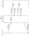
図2は本実施形態のログブロック262aの同期リモートコピー処理の処理概要を示す図である。図2に示す様に正ホストコンピュータ1からログブロック262aの書き込みを要求する正ログWRITE要求が送信されると、正ディスクサブシステム2は、その書き込み要求と共に送信されたログブロック262aをキャッシュ22に書き込み、副ディスクサブシステム4へ送信して副ディスクサブシステム4でのログブロック262aのリモートコピーを要求し、その完了を待つ。
【0054】
正ディスクサブシステム2からログブロック262aの書き込みを要求するコマンドが送信されると、副ディスクサブシステム4は、その書き込み要求と共に送信されたログブロック262aをキャッシュ22に書き込んだ後、その書き込みが完了したことを示すリモートコピー完了通知を生成して正ディスクサブシステム2へ送信する。
【0055】
正ディスクサブシステム2は、副ディスクサブシステム4からリモートコピー完了通知を受信すると、正ホストコンピュータ1から要求されたログブロック262aの書き込みが完了したことを示す正ログWRITE完了通知を生成して正ホストコンピュータ1へ送信する。
【0056】
図3は本実施形態のDBブロックやステータス情報の非同期リモートコピー処理の処理概要を示す図である。図3に示す様に正ホストコンピュータ1からDBブロックやステータス情報の書き込みを要求する正DBWRITE要求が送信されると、正ディスクサブシステム2は、その書き込み要求と共に送信されたDBブロックやステータス情報をキャッシュ22に書き込んだ後、正ディスクサブシステム2内のメモリまたは磁気ディスク中のキューに一時的に蓄積し、正ホストコンピュータ1から要求されたDBブロック242aの書き込みが完了したことを示す正DBWRITE完了通知を生成して正ホストコンピュータ1へ送信する。
【0057】
その後、正ディスクサブシステム2は、その蓄積したDBブッロクやステータス情報を副ディスクサブシステム4へ送信して副ディスクサブシステム4へのDBブロックまたはステータス情報のリモートコピーを要求し、その完了を待つ。
【0058】
正ディスクサブシステム2からDBブロックまたはステータス情報の書き込みを要求するリモートコピー要求が送信されると、副ディスクサブシステム4は、そのリモートコピー要求と共に送信されたDBブロックやステータス情報を受領した後、その要求が完了したことを示すリモートコピー完了通知を生成して正ディスクサブシステム2へ送信する。
【0059】
図4は本実施形態のDB−ディスクマッピングテーブル15の構成情報を示す図である。図4に示す様にDB−ディスクマッピングテーブル15は、正DB用ディスク24中のデータベース領域を識別する為の情報であるデータベース領域IDと、そのデータベース領域IDで識別されるデータベース領域が複数のファイルで構成される場合のファイルの順序番号を示すファイルIDと、そのデータベース領域中のデータがデータベースデータ、ログ情報またはステータス情報をいずれであるかを示す種別とを格納している。
【0060】
また、そのデータベース領域がマッピングされているディスク制御装置を識別する為のディスク制御装置番号と、そのディスク制御装置番号のディスク制御装置で制御されている磁気ディスク装置の内で前記データベース領域がマッピングされている磁気ディスク装置のドライブ番号を識別する為の物理デバイスIDについて、正ディスクサブシステム2及び副ディスクサブシステム4のそれぞれのIDを格納している。
【0061】
また、副ディスクサブシステム4のDB−ディスクマッピングテーブル35も、正ディスクサブシステム2のDB−ディスクマッピングテーブル15と同様な構成であるものとする。
【0062】
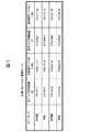
図5は本実施形態の正/副リモートコピー管理テーブルの例を示す図である。図5に示す様に正リモートコピー管理テーブル213や副リモートコピー管理テーブル413には、書き込み処理が同期または非同期のいずれで行われるかを示すコピーモードと、そのコピーモードで書き込み処理が行われるディスク制御装置のディスク制御装置番号及びその磁気ディスク装置の物理デバイスIDについて、正ディスクサブシステム2及び副ディスクサブシステム4のそれぞれのIDを格納している。
【0063】
図4のDB−ディスクマッピングテーブル15と図5の正リモートコピー管理テーブル213の情報により、ログブロック、DBブロック及びステータス情報がそれぞれ同期または非同期のどちらで副ディスクサブシステムへ書き込まれるかがわかる。例えば、データベース領域ID「LOG1」のログブロックは、図4より正ディスク制御装置IDが「CTL#A1」で正物理デバイスIDが「VOL12-A」の磁気ディスク装置に書き込まれるが、図5から正ディスク制御装置ID「CTL#A1」で正物理デバイスID「VOL12-A」の磁気ディスク装置のコピーモードは「同期」であるので、データベース領域ID「LOG1」のログブロックは、同期リモートコピー処理により副ディスクサブシステム4へ書き込まれる。
【0064】
一方、待機系となるシステムも同様な構成であり、正ディスクサブシステム2と副ディスクサブシステム4との間はネットワークを通して接続されているものとするが、待機中の状態では副ホストコンピュータ3は稼働しておらず、副ディスクサブシステム4は、正ディスクサブシステム2からネットワーク経由でログブロック、DBブロック及びステータス情報を受け取って、それぞれに対応するディスクの更新を行う。
【0065】
前記の様に本実施形態の正ホストコンピュータ1のチェックポイント処理部112は、チェックポイントを取得する際に、DBバッファ12上で更新された全DBブロックを正DB用ディスク24に格納し、その際のログレコードの位置を示すステータス情報を正ステータス用ディスク25に格納しており、以下に、このチェックポイント取得処理について説明する。
【0066】
図6は本実施形態のチェックポイント取得処理の処理手順を示すフローチャートである。図6に示す様に正ホストコンピュータ1のチェックポイント処理部112は、正ホストコンピュータ1のDBバッファ12の内容を現用系のディスクサブシステムである正ディスクサブシステム2内の記憶装置へ反映させる必要が生じた場合に、DBバッファ12で更新された全DBブロック及びその時点で最新のログレコードの位置を示すステータス情報の書き込み要求を正ホストコンピュータ1から正ディスクサブシステム2へ送信する処理を行う。
【0067】
ステップ701でチェックポイント処理部112は、チェックポイントの取得を開始したことを示すチェックポイント取得開始ログを生成してログブロック262aに格納する。
【0068】
ステップ702では、DBバッファ12上で更新されている全DBブロックを正ディスクサブシステム2へ書き込む為のWRITEコマンドを生成し、そのWRITEコマンドを正ディスクサブシステム2へ送信してDBブロックの書き込み要求を行う。正ディスクサブシステム2では、前記WRITEコマンドを受信してDBブロックをキャッシュメモリ22に書き込み、DBバッファ12の更新内容をキャッシュメモリ22に反映させる。
ステップ703は本実施例の最後で説明する。
【0069】
ステップ704では、チェックポイントの取得を終了したことを示すチェックポイント取得終了ログを生成してログブロック262aに格納する。
ステップ705では、前記チェックポイント取得終了ログのLSN(Log Sequence Number)をステータス情報として正ディスクサブシステム2へ書き込む為のWRITEコマンドを生成し、そのWRITEコマンドを正ディスクサブシステム2へ送信してステータス情報の書き込み要求を行う。正ディスクサブシステム2では、前記WRITEコマンドを受信してステータス情報を正ステータス用ディスク25に書き込む。
【0070】
現用系データベース処理システムでのデータベース処理が障害等により異常終了し、その後、現用系データベース処理システムでの処理を再開した場合には、正ステータス用ディスク25中のステータス情報で示される位置からログレコードを読み出して正DB用ディスク24のデータを当該ログレコードの内容に従って更新することにより、終了直前までに完了していたデータベースの状態を回復することができる。
【0071】
次に、本実施形態のディザスタリカバリシステムにおいて、正ホストコンピュータ1からの正ディスクサブシステム2へ、ログブロック、DBブロックまたはステータス情報の書き込みが要求された場合の正ディスクサブシステム2の処理について説明する。
【0072】
図7は本実施形態のWRITEコマンド受領時の処理手順を示すフローチャートである。図7の様に正ディスクサブシステムのコマンド処理部211は、正ホストコンピュータ1からコマンドを受領すると、受信コマンドからコマンド種類とアクセス先アドレスを解析し、WRITEコマンドであることを認識する(ステップ341)。ここで、アクセス先アドレスからは、複数のディスクサブシステムやその各磁気ディスク装置に割り当てられているアドレスを示す装置構成管理テーブルの情報との比較を行うことにより、アクセス要求先のデバイスIDを取得することができるものとする。
【0073】
次に、ステップ341で解析したアクセス先アドレスのデータが、正ディスクサブシステム2のキャッシュメモリ22に保持されているかどうかを調べ、キャッシュヒットミス判定を行う(ステップ342)。
【0074】
アクセス先データがキャッシュメモリ22に保持されていないキャッシュミスの場合には、転送先キャッシュエリアを確保する。転送先のキャッシュアドレスはキャッシュの空きリスト等、一般的な方法で管理、取得する。
【0075】
ステップ342でキャッシュヒットの判定の場合、またはステップ344でキャッシュエリアの確保が終了した場合には、正ディスクサブシステム2内のキャッシュメモリ22に対して当該データの更新を行う(ステップ345)。すなわち、正ホストコンピュータ1から受領したDBブロック242a、前記ステータス情報またはログブロック262aの内容をキャッシュメモリ22へ書き込む。
【0076】
ステップ346では、正リモートコピー管理テーブル213を参照し、前記アクセス先アドレスで示される正ディスク制御装置ID及び正物理デバイスIDに対応するコピーモードを読み出し、そのコピーモードが「同期」であるかどうかを判定する。
【0077】
その判定の結果、コピーモードが「同期」、すなわち、前記受領した書き込み要求がログブロック262aの書き込み要求である場合にはステップ347へ進み、ステップ347では、当該同期リモートコピーの完了を待つことにより、ログブロック262aの同期リモートコピー処理を行う。
【0078】
また、コピーモードが「非同期」、すなわち、前記受領した書き込み要求がDBブロック242aまたはステータス情報の書き込み要求である場合にはステップ348へ進み、ステップ348では、その後に行われる副ディスクサブシステム4への非同期リモートコピー処理の為に、受領しているデータを正ディスクサブシステム2内のメモリまたは磁気ディスク中のキューに一時的に蓄積しておく。
そしてステップ349では、正ホストコンピュータ1に対してWRITEコマンド処理の完了報告を行う。
【0079】
正ディスクサブシステム2は、その蓄積したデータを副ディスクサブシステム4へ送信して副ディスクサブシステム4へのDBブロックまたはステータス情報の非同期リモートコピー処理を実行する。
【0080】
図8は本実施形態のREADコマンド受領時の処理手順を示すフローチャートである。図8の様にコマンド処理部211は、正ホストコンピュータからコマンドを受領すると、受信コマンドからコマンドの種類とアクセス先アドレスを解析し、READアクセス要求であることを認識する(ステップ361)。ここで、アクセス先アドレスからアクセス要求先のデバイスIDを取得できるものとする。
【0081】
次に、ステップ361で解析したアクセス先アドレスのデータが、正ディスクサブシステム2のキャッシュメモリ22に保持されているかどうかを調べ、キャッシュヒットミス判定を行う(ステップ362)。
【0082】
アクセス先データがキャッシュメモリ22に保持されていないキャッシュミスの場合には、前記の様にアクセス要求先のデバイスIDを識別し、正ディスクサブシステム2のディスクアクセス制御部23に対してそのデバイスIDに対応する磁気ディスク装置からキャッシュメモリ22ヘの転送依頼を行う(ステップ363)。この場合、転送終了までREAD処理を中断し(ステップ364)、転送処理終了後、再度READ処理を継続する。また、転送先のキャッシュアドレスはキャッシュの空きリスト等、一般的な方法で管理、取得すれば良いが、転送先アドレスについては、キャッシュ管理テーブルを更新することで登録する必要がある。
【0083】
ステップ362でキャッシュヒットの判定の場合、またはステップ364で転送処理が終了した場合、当該ディスクサブシステム内のキャッシュメモリのデータをチャネルに転送する(ステップ365)。
【0084】
次に、本実施形態のディザスタリカバリシステムにおいて、正ディスクサブシステム2から副ディスクサブシステム4へ、ログブロックの同期書き込みや、DBブロックまたはステータス情報の非同期による書き込みが要求された場合の副ディスクサブシステム4の処理について説明する。
【0085】
図9は本実施形態の副ディスクサブシステム4のデータ受信処理の処理手順を示すフローチャートである。図9の様に副ディスクサブシステム4の副リモートコピー処理部412は、コマンドを受領すると、受信コマンドからコマンド種類とアクセス先アドレスを解析し、リモートコピーコマンドであることを認識する(ステップ421)。ここで、アクセス先アドレスからは、アクセス要求先のデバイスIDを識別することができるものとする。
【0086】
次に、ステップ421で解析したアクセス先アドレスのデータが、副ディスクサブシステム4のキャッシュメモリ42に保持されているかどうかを調べ、キャッシュヒットミス判定を行う(ステップ422)。
【0087】
アクセス先データがキャッシュメモリ42に保持されていないキャッシュミスの場合には、転送先キャッシュエリアを確保する。転送先のキャッシュアドレスはキャッシュの空きリスト等、一般的な方法で管理、取得すれば良いが、転送先アドレスについては、キャッシュ管理テーブルを更新することで登録する必要がある。
【0088】
ステップ422でキャッシュヒットの判定の場合、またはステップ424が終了した場合には、正ディスクサブシステム2内のキャッシュメモリ22に対して当該データの更新を行う(ステップ425)。すなわち、正ディスクサブシステム2から受信したDBブロック242a、前記ステータス情報またはログブロック262aの内容をキャッシュメモリ42へ書き込む。以上は同期リモートコピーの場合であり、非同期リモートコピーの場合で特開平11−85408「記憶制御装置」に示すような順序性を保証する場合はキャッシュ上での更新前にそれまでに到着すべきデータがすべて揃っていることを確認することが必要である。そしてステップ426では、正ディスクサブシステム2に対してリモートコピーコマンド処理の完了報告を行う。
【0089】
前記の様に本実施形態のディザスタリカバリシステムでは、ログブロックの書き込み要求については、正ディスクサブシステム2での書き込みと同期した副ディスクサブシステム4への同期リモートコピー処理を行うので、現用系で完了済みのトランザクションの更新内容が待機系で失われる事を無くすことができる。また、DBブロックやステータス情報の書き込みについては、正ディスクサブシステム2での書き込みとは同期しない副ディスクサブシステム4への非同期リモートコピー処理を行うので、現用系のパフォーマンス劣化をできるだけ防ぐことができる。
【0090】
前記の様にして、副ディスクサブシステム4への書き込みを行った後、現用系データベース処理システムで障害が発生し、待機系データベース処理システムでデータベース処理が開始されると、そのDBMS開始処理では、副ステータス用ディスク45内のステータス情報で示される位置からログ情報を読み出して副ディスクサブシステム4の副DB用ディスク44を、障害発生直前の現用系のデータベース領域の状態に回復する。
【0091】
図10は本実施形態のDBMS開始処理の処理手順を示すフローチャートである。現用系から待機系への切り替えが行われ、待機系データベース処理システムでのデータベース処理が開始されると、副ホストコンピュータ3のDBアクセス制御部311は、副ディスクサブシステム4に対してDBMS開始処理の実行を指示する。
【0092】
ステップ1201で副ディスクサブシステム4のコマンド処理部411は、副ステータス用ディスク45中のステータスファイルを読み出し、データベースの状態を示す情報を取得する。ここで、ステータファイルには、データベースの状態を示す情報として、DBMSが稼働中であることを示す情報をデータベース処理開始時に格納し、DBMSが正常終了したことを示す情報をデータベース処理終了時に格納しているものとする。
【0093】
ステップ1202では、前記取得したデータベースの状態を示す情報を参照して前回のデータベース処理が正常終了しているかどうかを調べ、前記取得したデータベースの状態がDBMSの稼働中であることを示している場合、すなわちDBMSが正常終了したことを示す情報がステータファイルに記録されていない場合には、前回のデータベース処理が正常終了していないものとしてステップ1203へ進む。
ステップ1203では、直前のチェックポイント時のログレコードの位置を示すステータス情報を参照し、ログレコードの入力位置を取得する。
【0094】
ステップ1204では、副ログ用ディスク46を参照して前記取得した入力位置からログレコードを読み出し、副DB用ディスク44中のデータベース領域に対してROLLFOWARD処理を行う。
【0095】
ステップ1205では、前記ログレコードによるROLLFOWARD処理を行ったトランザクションの内、完了していないトランザクションの処理を取り消すROLLBACK処理を行う。
【0096】
ステップ1206では、DBMSが稼働中であることを示す情報と回復後のログレコードの位置を示すステータス情報を副ステータス用ディスク45中のステータスファイルに格納する。
【0097】
一般に従来のDBMSでは、トランザクションの実行性能を確保する為、トランザクション内で更新したデータを該当トランザクションの完了(commit)に同期してストレージに書き出しておらず、所定のトランザクション発生回数や所定時間を契機としたチェックポイントと呼ばれる契機を設け、ここでその間のDB更新データのストレージへの書き出しを行っている。そして、チェックポイント以降のDB更新内容をログ用ディスクに書き出しておき、サーバダウン時のリスタート処理では、チェックポイント以降のDB更新をログ用ディスク内の更新履歴から復元して回復している。
【0098】
ここで、サーバダウン後のリスタート時に、最新のチェックポイント以降はどのログ用ディスクのどの位置からログ情報を反映すれば良いかが問題となるが、一般に、こうした情報はログ用ディスクのヘッダ部等に持っており、リスタート時に反映対象とするログ用ディスクと読み込み位置をその情報により決定している。
【0099】
この様な従来のDBMSにおいて、ログ用ディスクを同期コピーし、DB用ディスクを非同期コピーした場合、メインサイトのログ用ディスク上ではチェックポイント済みのDB更新内容がリモートサイトに転送されていない可能性があり、メインサイト側でチェックポイント時点にストレージに反映したDB更新データがリモートサイトでは失われて、回復が不整合になってしまう。
【0100】
これに対し、本実施形態のディザスタリカバリシステムでは、ログブロックを同期リモートコピー処理し、DBブロックを非同期リモートコピー処理しても副ディスクサブシステム4での回復で不整合が起こらない様に、チェックポイント時のログ用ディスク入力ポイントを管理する為のステータスファイルを設け、更に、そのステータスファイルを非同期リモートコピー処理により転送し、同様に非同期で転送されるDBブロックとの更新順序を副ディスクサブシステム4で保証する様にしている。
【0101】
これにより、現用系から待機系への切り替え後、データベース処理の開始時に副ステータス用ディスク45のステータスファイルを参照し、そのステータス情報で示される位置から回復すれば良いことになる。
【0102】
前記の様に本実施形態のディザスタリカバリシステムでは、チェックポイント時の書き込み要求も非同期で副ディスクサブシステム4へ送信しているが、チェックポイント時の書き込み要求が行われた場合には、その書き込み要求とその時点までに非同期書き込みの為に一時的に蓄積している書き込み要求を、副ディスクサブシステム4へ送信するものとしても良い。
【0103】
図11は本実施形態のチェックポイント時の処理概要を示す図である。図11に示す様に正ホストコンピュータ1から正DB用ディスク24のチェックポイントを要求する正DBボリュームチェックポイント要求が送信されると、正ディスクサブシステム2は、その時点で正ディスクサブシステム2内のメモリまたは磁気ディスク中のキューに一時的に蓄積しているリモートコピー用データを副ディスクサブシステム4へ送信し、正DBボリュームチェックポイント要求で受信したDBブロック242a及びステータス情報を副ディスクサブシステム4へ送信する。
【0104】
副ディスクサブシステム4は、その書き込み要求と共に送信されたDBブロック242aやステータス情報をすべてキャッシュ42に書き込んだ後、その書き込みが完了したことを示すリモートコピー完了通知を生成して正ディスクサブシステム2へ送信する。
【0105】
正ディスクサブシステム2は、副ディスクサブシステム4からリモートコピー完了通知を受信すると、正ホストコンピュータ1から要求されたチェックポイント処理が完了したことを示す正DBボリュームチェックポイント完了通知を生成して正ホストコンピュータ1へ送信する。
【0106】
前記の様に本実施形態のディザスタリカバリシステムにおいて、ログブロックの書き込み要求時とチェックポイント要求時に、正ディスクサブシステム2と副ディスクサブシステム4の同期化処理を行った場合には、現用系で完了済みのトランザクションの更新内容が待機系で失われる事を無くすと共に、DBブロックやステータス情報の書き込みをチェックポイント時にまとめて行うことにより、DBブロックやステータス情報をすべて同期リモートコピーで転送した場合に比べ現用系のパフォーマンス劣化を防ぐことができる。また、この場合には、専用のステータスファイルを備えていないデータベース管理システムを用いた構成でも、現用系でチェックポイント時点にストレージに反映したDB更新データが待機系で失われることが無い。
【0107】
以上説明した様に本実施形態のディザスタリカバリシステムによれば、待機系への書き込み要求時に、同期書き込みによりログ情報を更新し、非同期書き込みによりデータベースデータ及びステータス情報を更新するので、現用系で完了済みのトランザクションの更新内容が待機系で失われる事が無く、現用系のパフォーマンス劣化が少ない災害対策システムを構築することが可能である。
【0108】
【発明の効果】
本発明によればトランザクション処理の実行完了済みのトランザクション更新内容が失われる可能性を低くすることが可能になる。
【図面の簡単な説明】
【図1】本実施形態のディザスタリカバリシステムのシステム構成を示す図である。
【図2】本実施形態のログブロック262aの同期リモートコピー処理の処理概要を示す図である。
【図3】本実施形態のDBブロックやステータス情報の非同期リモートコピー処理の処理概要を示す図である。
【図4】本実施形態のDB−ディスクマッピングテーブル15の構成情報を示す図である。
【図5】本実施形態の正/副リモートコピー管理テーブルの例を示す図である。
【図6】本実施形態のチェックポイント取得処理の処理手順を示すフローチャートである。
【図7】本実施形態のWRITEコマンド受領時の処理手順を示すフローチャートである。
【図8】本実施形態のREADコマンド受領時の処理手順を示すフローチャートである。
【図9】本実施形態の副ディスクサブシステム4のデータ受信処理の処理手順を示すフローチャートである。
【図10】本実施形態のDBMS開始処理の処理手順を示すフローチャートである。
【図11】本実施形態のチェックポイント時の同期リモートコピー処理の処理概要を示す図である。
【符号の説明】
1…正ホストコンピュータ、12…DBバッファ、14…ログバッファ、15…DB−ディスクマッピングテーブル、2…正ディスクサブシステム、213…正リモートコピー管理テーブル、22…キャッシュメモリ、24…正DB用ディスク、242…DBブロック、25…正ステータス用ディスク、26…正ログ用ディスク、262…ログブロック、3…副ホストコンピュータ、32…DBバッファ、34…ログバッファ、35…DB−ディスクマッピングテーブル、4…副ディスクサブシステム、413…副リモートコピー管理テーブル、42…キャッシュメモリ、44…副DB用ディスク、442…DBブロック、45…副ステータス用ディスク、46…副ログ用ディスク、462…ログブロック、111…DBアクセス制御部、112…チェックポイント処理部、113…ログ管理部、114…DB遅延書き込み処理部、21…ディスク制御処理部、211…コマンド処理部、212…正リモートコピー処理部、23…ディスクアクセス制御部、311…DBアクセス制御部、312…チェックポイント処理部、313…ログ管理部、314…DB遅延書き込み処理部、41…ディスク制御処理部、411…コマンド処理部、412…副リモートコピー処理部、43…ディスクアクセス制御部。[0001]
BACKGROUND OF THE INVENTION
The present invention relates to a technique for executing processing by another information processing apparatus, a program for executing the processing, or an object when a failure occurs or when a predetermined condition is generated or requested.
[0002]
[Prior art]
In a conventional database management system (or computer system or information processing system), there is a so-called disaster recovery method in which copies are made on a plurality of geographically separated sites (computers or information processing devices) in preparation for a failure. In this method, data of a certain site is stored as a copy in another geographically distant site, and when a certain site has a failure due to a disaster or the like, the business is restored at the other site.
[0003]
In a database management system (or a computer system or an information processing system, here a database management system is taken as an example), there are several methods for having such a copy. Basically, a request is sent to the main system as viewed from the client, that is, the active system, and a record of information called a log is generated in the active system, which is used for processing recovery or as a backup. In other words, this log record is sent from the active system to a system called the standby system, and the standby host computer updates the status of the standby system by referring to this log record and performing the same update processing as the active system. Such a technique that realizes replication by sending a log record generated in the active system to the standby system is disclosed in
[0004]
Conventionally, there are mainly the following two types of data transfer methods in the remote copy function (see Patent Document 1) by a storage device used when sending log records and database data generated in the active system to the standby system. It is divided roughly.
[0005]
(1) Synchronization method
When a data write request is received from a host computer at a certain site (referred to as the main site here), the storage device at the main site transfers the corresponding data to the storage device at the other site (referred to as the remote site here) and from the storage device at the remote site. After receiving the corresponding data receipt report, the storage device at the main site reports the completion of writing to the host computer at the main site.
[0006]
While there is an advantage that data is guaranteed to arrive at the remote site at the time of completion of writing at the main site, the write response time at the main site increases due to the increase in the distance between the sites and the line delay, leading to performance degradation There is.
[0007]
(2) Asynchronous method
The storage device at the main site reports the completion of writing to the host computer at the main site without waiting for completion of the data transfer to the remote site at the time of a data write request from the host computer at the main site.
[0008]
Although there is less possibility of performance degradation at the main site compared to the synchronous method, if a failure occurs at the main site, the latest data may be lost at the remote site and the transaction may be lost.
[0009]
As for asynchronous remote copy, there are a method for guaranteeing that the order of data writing is the same at the main site and the remote site as disclosed in
[0010]
Generally, a database management system (DBMS) has a DB disk for storing data itself and a log disk for storing DB update history information in time series. If the server at the main site (computer or information processing device at the main site) goes down due to the occurrence of a disaster, the data on the DB disk may be halfway updated. The database is restored to a consistent state based on the DB update history information (Non-Patent
[0011]
In addition, the followings are known as transfer methods in the disaster countermeasure system.
(A) Log synchronization, DB synchronization method
Transfer log and DB to remote site synchronously. Since the remote site always has the same log and DB status as the main site, when a failure occurs, recovery processing in the same situation as the restart at the main site can also be realized at the remote site. That is, the updated content of the transaction completed at the main site is not lost at the remote site. However, since the log and DB are transferred synchronously, the performance on the main site side is degraded as compared with the case where such a configuration is not adopted.
(B) Log asynchronous, DB asynchronous method
Logs and DBs are transferred asynchronously to the remote site and the update order on the remote site side is guaranteed. Since the update on the remote site side is delayed, the remote site side has the log and DB status before the main site side delay time. If the log and DB update order is guaranteed, when a failure occurs, the remote site can be restarted to restore a consistent DB state before the main site delay time. Although the performance degradation on the main site side is small, transaction updates completed at the main site may be lost on the remote site side.
[0012]
[Patent Document 1]
US Pat. No. 5,640,561
[Non-Patent Document 1]
“TRANSCATION PROCESSING; Concepts and Techniques” by Jim Gray, Andreas Reuter, published by MORGAN KAUFMANN PUBLISHERS
[0013]
[Problems to be solved by the invention]
As described above, in a conventional database management system (or a computer system or an information processing system, here a database management system is taken as an example), a log and a DB (a database is taken as an example here, but used for processing) If the data stored in the main site is transferred to the remote site in synchronization with the main site, it is unlikely that the updated contents of the transaction completed at the main site will be lost at the remote site. There is a problem that the performance on the main site side is deteriorated as compared with the case where such a configuration is not adopted.
[0014]
In addition, when logs and DBs are transferred asynchronously to a remote site in a conventional database management system, performance degradation on the main site side is small, but transaction updates that have been completed on the main site may be lost on the remote site side. The problem that there is.
[0015]
The object of the present invention is that when the execution of a process is performed by another information processing apparatus or a program or object for executing the process when a failure occurs or a predetermined condition is generated or requested, the update contents of a completed transaction may be lost. Is to provide low technology.
A second object of the present invention is to provide a technique that is unlikely to lose the updated contents of a transaction completed in the active system in the standby system.
A third object of the present invention is to provide a technique capable of reducing performance degradation of the active system.
[0016]
[Means for Solving the Problems]
The first means stores the processing data and the data at the time of failure of the processing in the first program that stores the data processed by the first program and the log information for recovering the processing in the first storage means. The following processing in the information processing recovery method for recovering the processing in which the failure has occurred by executing the processing of the second program stored in the second storage means for storing the log information for recovering the processing To implement.
[0017]
In response to an input of a write request for status information indicating the storage location of the log information, the processing data, and the log information, first, the log information, the processing data, and the status information stored in the storage unit are Storing in the storage means and responding to the write request when the log information is stored in the second storage means,
The processing data and the status information stored in the first storage unit are stored in the second storage unit when a predetermined condition is satisfied.
[0018]
The second means switches to the second database processing system when the failure of the first database processing system occurs and performs the following processing in the system that continues the database processing. At the time of a write request to the second database processing system, log information is updated by synchronous writing, and database data and status information are updated by asynchronous writing.
[0019]
In a disaster recovery system that switches to the standby database processing system and continues database processing when a failure occurs in the active database processing system, the third means updates the log information by synchronous writing at the time of a write request to the standby system, Database data and status information are updated by asynchronous writing.
[0020]
In the disaster recovery system of the present invention, a host computer is provided with a database buffer that temporarily holds the contents of the database area in the storage subsystem and a log buffer that temporarily holds the contents of the update processing for the database buffer. If the contents of the database buffer are changed as the database processing is executed on the host computer, and the change needs to be reflected in the database area in the storage subsystem, it is performed on the database buffer. A request to write log information indicating the contents of the update processing, database data updated in the database buffer, or status information indicating the position of log information at the time of the checkpoint is sent from the active primary host computer to the active primary storage subsystem. To send to.
[0021]
The primary storage device subsystem receives the write request from the primary host computer, and updates the log information, database area data, and status information in the primary storage device subsystem in accordance with the contents of the received write request. Configure the primary storage subsystem to perform synchronous remote copy for the log information disk in advance and asynchronous remote copy that guarantees the update order for both the data disk and status information disk in the database area. Keep it.
[0022]
According to this configuration, the primary storage subsystem writes write requests to the log information disk synchronously in the standby secondary storage device, and writes requests to the database area data disk and status information disk asynchronously. Write to standby secondary storage.
[0023]
In the secondary storage subsystem, the log information, database data or status information write request is received from the primary storage subsystem, and the log information and database area in the secondary storage subsystem are received according to the contents of the received write request. The data and status information are updated (see Patent Document 1).
[0024]
Thereafter, when a failure occurs in the active database processing system and the database processing is started in the standby database processing system, the log information is read from the position indicated by the status information, and the database area on the secondary storage subsystem is read. The data is updated according to the contents of the read log information, and thereby the database area on the secondary storage subsystem is restored to the state of the consistent database area immediately before the occurrence of the failure.
[0025]
In business processing with a high DB update ratio, the I / O load on the DB disk is higher than that of the log disk. On the other hand, the transaction to be recovered in the standby system is determined by the information on the log disk. Therefore, by synchronously copying the information on the log disk, the updated contents of transactions that have been completed on the active system are not lost on the standby system. A disaster countermeasure system with little performance degradation can be constructed.
[0026]
As described above, according to the disaster recovery system of the present invention, when writing to the standby system is requested, the log information is updated by synchronous writing and the database data and status information are updated by asynchronous writing. It is possible to construct a disaster countermeasure system in which transaction updates are not lost in the standby system and the performance degradation of the active system is small.
[0027]
DETAILED DESCRIPTION OF THE INVENTION
The following describes a system according to an embodiment that updates log information by synchronous writing and updates database data and status information by asynchronous writing when a write request is made to the standby system.
[0028]
FIG. 1 is a diagram showing a system configuration of the present embodiment. As shown in FIG. 1, the primary host computer 1 (which may be realized by a computer, an information processing apparatus, or a program or object capable of executing the processing) of the present embodiment has a DB access control unit 111 (can execute the processing). Hardware, programs, and objects), a checkpoint processing unit 112 (hardware, programs, and objects that can perform the processing), and a log management unit 113 (hardware, programs, and objects that can perform the processing) And a DB delayed write processing unit 114 (hardware, programs, and objects capable of executing the processing).
[0029]
The DB access control unit 111 controls access to the primary DB disk 24 (storage means) and the primary log disk 26 (storage means) via the DB buffer 12 (storage means) and the log buffer 14 (storage means). It is a processing unit. The checkpoint processing unit 112 updates the DB buffer 12 when the contents of the DB buffer 12 of the
[0030]
As disclosed in
[0031]
The log management unit 113 is a processing unit that transmits a write request for the
[0032]
A program for causing the
[0033]
The primary disk subsystem 2 (which may be realized by a storage device, a disk system, a computer, an information processing device, or a program or an object capable of executing the processing) includes a disk control processing unit 21 (hardware capable of executing the processing). , A
[0034]
The disk control processing unit 21 is a control processing unit that controls the operation of the entire primary disk subsystem. The
[0035]
The primary remote copy processing unit 212 is a processing unit that refers to the primary remote copy management table and performs synchronous or asynchronous remote copy according to the configuration information. In the case of the present embodiment, when the received write request is a write request for the
[0036]
A program for causing the primary disk subsystem 2 to function as the disk control processing unit 21, the
[0037]
The secondary host computer 3 (which may be realized by a computer, an information processing apparatus, or a program or object that can execute the process) includes a DB access control unit 311 (hardware, program, or object that can execute the process), Checkpoint processing unit 312 (hardware, program, or object that can execute the process), log management unit 313 (hardware, program, or object that can execute the process), and DB delayed write processing unit 314 (processing thereof) Hardware, programs, and objects).
[0038]
The DB access control unit 311 is a processing unit that performs the same processing as that of the active DB access control unit 111 during standby system operation. The checkpoint processing unit 312 is a processing unit that performs the same processing as the active checkpoint processing unit 112 during standby system operation.
[0039]
The log management unit 313 is a processing unit that performs the same processing as the active log management unit 113 during standby system operation. The DB delayed write processing unit 314 is a processing unit DB that performs the same processing as the active DB delayed write processing unit 114 during standby system operation.
[0040]
A program for causing the secondary host computer 3 to function as the DB access control unit 311, the checkpoint processing unit 312, the log management unit 313, and the DB delayed write processing unit 314 is recorded on a recording medium such as a CD-ROM and stored on a magnetic disk or the like. It is assumed that after being stored, it is loaded into memory and executed. The recording medium for recording the program may be a recording medium other than the CD-ROM. The program may be used by installing it from the recording medium into the information processing apparatus, or the program may be used by accessing the recording medium through a network.
[0041]
The secondary disk subsystem 4 (which may be realized by a storage device, a disk system, a computer, an information processing device, or a program or object capable of executing the processing) is a disk control processing unit 41 (hardware capable of performing the processing). , A program or object), a command processing unit 411 (hardware, program or object that can execute the process), a secondary remote copy processing unit 412 (hardware, program or object that can execute the process), a disk And an access control unit 43 (hardware, programs and objects capable of executing the processing).
[0042]
The disk control processing unit 41 is a control processing unit that controls the operation of the entire secondary disk subsystem. The command processing unit 411 switches the status information in the secondary status disk 45 in response to an instruction from the secondary host computer 3 when the active system is switched to the standby system and the database processing in the standby database processing system is started. The log record is read out from the position of the log block 462a shown in FIG. The data of the secondary DB disk 44 on the secondary disk subsystem 4 is updated according to the instruction of the secondary host computer 3 in accordance with the contents of the log record analyzed by the secondary host computer 3, so that the secondary DB disk on the secondary disk subsystem 4 is updated. The process of recovering the state of the disk 44 to the state of the primary DB disk 24 immediately before switching to the standby system, the secondary DB disk 44, the secondary status disk 45, and the secondary log disk 46 associated with the database processing after switching. It is a processing unit that performs an update.
[0043]
The secondary remote copy processing unit 412 receives a write request for the DB block 242a, the status information or the
[0044]
A program for causing the secondary disk subsystem 4 to function as the disk control processing unit 41, the command processing unit 411, the secondary remote copy processing unit 412 and the disk access control unit 43 is recorded on a recording medium such as a floppy disk and executed. Shall. The recording medium for recording the program may be a recording medium other than the floppy disk. The program may be used by installing it from the recording medium into the information processing apparatus, or the program may be used by accessing the recording medium through a network.
[0045]
In the disaster recovery system of this embodiment, the primary disk subsystem 2 of the
[0046]
In the
[0047]
In the primary disk subsystem 2, the disk control processing unit 21, the cache memory 22, and the disk access control unit 23 that operate in response to an instruction from the
[0048]
When access to the primary DB disk 24 is requested by a transaction, the DB access control unit 111 of the
[0049]
The checkpoint processing unit 112 uses the contents of the DB buffer 12 of the
[0050]
When a transaction is committed, the log management unit 113 is stored in the log buffer 14 when a predetermined time elapses after recording of log information is started or when a predetermined condition such as the log buffer 14 is exhausted is reached. As a request to write the
[0051]
The DB delayed write processing unit 114 performs the primary DB of the DB block 242a on the DB buffer 12 when a predetermined condition such as a predetermined time elapses after the database processing is started or when the DB buffer 12 is full. As a write request to the primary disk 24, a WRITE command for writing the DB block 242a is generated and transmitted from the
[0052]
The primary disk subsystem 2 according to the present embodiment synchronizes the write request for the
[0053]
FIG. 2 is a diagram showing an outline of the synchronous remote copy process of the
[0054]
When a command requesting writing of the
[0055]
When the primary disk subsystem 2 receives the remote copy completion notification from the secondary disk subsystem 4, the primary disk subsystem 2 generates a primary log WRITE completion notification indicating that the writing of the
[0056]
FIG. 3 is a diagram showing an overview of the asynchronous remote copy processing of DB blocks and status information according to this embodiment. As shown in FIG. 3, when a primary DBWRITE request for requesting writing of a DB block and status information is transmitted from the
[0057]
Thereafter, the primary disk subsystem 2 sends the stored DB block and status information to the secondary disk subsystem 4 to request remote copy of the DB block or status information to the secondary disk subsystem 4 and waits for its completion. .
[0058]
When a remote copy request for requesting writing of DB block or status information is transmitted from the primary disk subsystem 2, the secondary disk subsystem 4 receives the DB block and status information transmitted together with the remote copy request, A remote copy completion notification indicating that the request is completed is generated and transmitted to the primary disk subsystem 2.
[0059]
FIG. 4 is a diagram showing the configuration information of the DB-disk mapping table 15 of this embodiment. As shown in FIG. 4, the DB-disk mapping table 15 includes a database area ID which is information for identifying a database area in the primary DB disk 24 and a database area identified by the database area ID. Stored in the database area and the type indicating whether the data in the database area is database data, log information or status information.
[0060]
In addition, a disk control unit number for identifying the disk control unit to which the database area is mapped, and the database area is mapped within the magnetic disk unit controlled by the disk control unit with the disk control unit number. The IDs of the primary disk subsystem 2 and the secondary disk subsystem 4 are stored as physical device IDs for identifying the drive number of the magnetic disk device being used.
[0061]
Further, the DB-disk mapping table 35 of the secondary disk subsystem 4 is assumed to have the same configuration as the DB-disk mapping table 15 of the primary disk subsystem 2.
[0062]
FIG. 5 is a diagram showing an example of the primary / secondary remote copy management table of this embodiment. As shown in FIG. 5, the primary remote copy management table 213 and the secondary remote copy management table 413 include a copy mode indicating whether the writing process is performed synchronously or asynchronously, and a disk on which the writing process is performed in the copy mode. The IDs of the primary disk subsystem 2 and secondary disk subsystem 4 are stored for the disk controller number of the controller and the physical device ID of the magnetic disk device.
[0063]
The information in the DB-disk mapping table 15 in FIG. 4 and the primary remote copy management table 213 in FIG. 5 indicates whether the log block, DB block, and status information are written to the secondary disk subsystem synchronously or asynchronously. For example, the log block of the database area ID “LOG1” is written to the magnetic disk device having the primary disk control device ID “CTL # A1” and the primary physical device ID “VOL12-A” from FIG. Since the copy mode of the magnetic disk device with the primary disk controller ID “CTL # A1” and the primary physical device ID “VOL12-A” is “synchronous”, the log block of the database area ID “LOG1” Is written to the secondary disk subsystem 4.
[0064]
On the other hand, the standby system has the same configuration, and the primary disk subsystem 2 and the secondary disk subsystem 4 are connected through a network, but the secondary host computer 3 is in a standby state. The secondary disk subsystem 4 is not operating, receives the log block, DB block, and status information from the primary disk subsystem 2 via the network, and updates the corresponding disk.
[0065]
As described above, the checkpoint processing unit 112 of the
[0066]
FIG. 6 is a flowchart showing a processing procedure of checkpoint acquisition processing according to the present embodiment. As shown in FIG. 6, the checkpoint processing unit 112 of the
[0067]
In
[0068]
In
Step 703 will be described at the end of this embodiment.
[0069]
In
In
[0070]
When the database processing in the active database processing system ends abnormally due to a failure or the like, and then the processing in the active database processing system is resumed, the log record from the position indicated by the status information in the
[0071]
Next, in the disaster recovery system of this embodiment, processing of the primary disk subsystem 2 when a write of a log block, DB block, or status information is requested from the
[0072]
FIG. 7 is a flowchart showing a processing procedure when a WRITE command is received according to this embodiment. As shown in FIG. 7, when the
[0073]
Next, it is checked whether or not the data of the access destination address analyzed in
[0074]
In the case of a cache miss in which the access destination data is not held in the cache memory 22, a transfer destination cache area is secured. The cache address of the transfer destination is managed and acquired by a general method such as a cache free list.
[0075]
If it is determined in
[0076]
In
[0077]
As a result of the determination, if the copy mode is “synchronous”, that is, if the received write request is a write request for the
[0078]
If the copy mode is "asynchronous", that is, if the received write request is a DB block 242a or status information write request, the process proceeds to step 348. In
In
[0079]
The primary disk subsystem 2 transmits the accumulated data to the secondary disk subsystem 4 and executes asynchronous remote copy processing of DB blocks or status information to the secondary disk subsystem 4.
[0080]
FIG. 8 is a flowchart showing a processing procedure when a READ command is received according to this embodiment. As shown in FIG. 8, when receiving a command from the primary host computer, the
[0081]
Next, it is checked whether or not the data of the access destination address analyzed in
[0082]
In the case of a cache miss in which the access destination data is not held in the cache memory 22, the device ID of the access request destination is identified as described above, and the device ID is given to the disk access control unit 23 of the primary disk subsystem 2. A request for transfer to the cache memory 22 is made from the magnetic disk device corresponding to (step 363). In this case, the READ process is interrupted until the transfer ends (step 364), and after the transfer process ends, the READ process is continued again. The transfer destination cache address may be managed and acquired by a general method such as a cache empty list, but the transfer destination address needs to be registered by updating the cache management table.
[0083]
If the cache hit is determined in
[0084]
Next, in the disaster recovery system of the present embodiment, the secondary disk subsystem when the synchronous writing of the log block or the asynchronous writing of the DB block or status information is requested from the primary disk subsystem 2 to the secondary disk subsystem 4. Processing of the system 4 will be described.
[0085]
FIG. 9 is a flowchart showing a processing procedure of data reception processing of the secondary disk subsystem 4 of this embodiment. As shown in FIG. 9, when receiving the command, the secondary remote copy processing unit 412 of the secondary disk subsystem 4 analyzes the command type and access destination address from the received command and recognizes that it is a remote copy command (step 421). . Here, it is assumed that the device ID of the access request destination can be identified from the access destination address.
[0086]
Next, it is checked whether or not the data of the access destination address analyzed in
[0087]
In the case of a cache miss in which the access destination data is not held in the
[0088]
If it is determined in
[0089]
As described above, in the disaster recovery system according to the present embodiment, the log block write request performs synchronous remote copy processing to the secondary disk subsystem 4 synchronized with the write in the primary disk subsystem 2, so It is possible to prevent the update contents of completed transactions from being lost in the standby system. As for the writing of DB blocks and status information, the asynchronous remote copy processing to the secondary disk subsystem 4 that is not synchronized with the writing in the primary disk subsystem 2 is performed, so that the performance degradation of the active system can be prevented as much as possible. .
[0090]
After writing to the secondary disk subsystem 4 as described above, when a failure occurs in the active database processing system and database processing is started in the standby database processing system, The log information is read from the position indicated by the status information in the secondary status disk 45, and the secondary DB disk 44 of the secondary disk subsystem 4 is restored to the state of the active database area immediately before the failure occurs.
[0091]
FIG. 10 is a flowchart showing the procedure of the DBMS start process according to this embodiment. When switching from the active system to the standby system is performed and database processing in the standby database processing system is started, the DB access control unit 311 of the secondary host computer 3 performs DBMS start processing for the secondary disk subsystem 4. Is instructed to execute.
[0092]
In
[0093]
In
In
[0094]
In
[0095]
In
[0096]
In
[0097]
In general, in order to ensure transaction execution performance in a conventional DBMS, data updated in a transaction is not written to the storage in synchronization with the completion of the corresponding transaction (commit). An opportunity called a checkpoint is provided, and DB update data in the meantime is written to the storage. Then, the DB update contents after the checkpoint are written to the log disk, and in the restart process when the server goes down, the DB update after the checkpoint is restored from the update history in the log disk and recovered.
[0098]
Here, when restarting after the server goes down, the problem is which log disk information should be reflected from which log disk after the latest checkpoint. Generally, this information is the header part of the log disk. The log disk to be reflected at the time of restart and the reading position are determined based on the information.
[0099]
In such a conventional DBMS, when the log disk is copied synchronously and the DB disk is asynchronously copied, the checkpointed DB update contents may not be transferred to the remote site on the main site log disk. Yes, the DB update data reflected in the storage at the checkpoint at the main site side is lost at the remote site, and the recovery becomes inconsistent.
[0100]
On the other hand, in the disaster recovery system of this embodiment, the log block is subjected to synchronous remote copy processing and the DB block is subjected to asynchronous remote copy processing so that inconsistency does not occur in recovery by the secondary disk subsystem 4. A status file is provided to manage the log disk input point at the point, and the status file is transferred by asynchronous remote copy processing. Similarly, the update order with the asynchronously transferred DB block is set as the secondary disk subsystem. 4 is guaranteed.
[0101]
As a result, after switching from the active system to the standby system, the status file of the secondary status disk 45 is referred to at the start of database processing, and recovery is performed from the position indicated by the status information.
[0102]
As described above, in the disaster recovery system of the present embodiment, the write request at the checkpoint is also asynchronously transmitted to the secondary disk subsystem 4, but when the write request at the checkpoint is made, the write request is performed. The request and a write request temporarily accumulated for asynchronous writing up to that point may be transmitted to the secondary disk subsystem 4.
[0103]
FIG. 11 is a diagram showing an outline of processing at the time of checkpoint in the present embodiment. As shown in FIG. 11, when a primary DB volume checkpoint request for requesting a checkpoint of the primary DB disk 24 is transmitted from the
[0104]
The secondary disk subsystem 4 writes all the DB blocks 242a and status information transmitted together with the write request to the
[0105]
When the primary disk subsystem 2 receives the remote copy completion notification from the secondary disk subsystem 4, the primary disk subsystem 2 generates a primary DB volume checkpoint completion notification indicating that the checkpoint processing requested from the
[0106]
As described above, in the disaster recovery system according to the present embodiment, when synchronization processing between the primary disk subsystem 2 and the secondary disk subsystem 4 is performed at the time of log block write request and checkpoint request, When the update contents of completed transactions are not lost in the standby system, and all DB blocks and status information are transferred by synchronous remote copy by collectively writing the DB blocks and status information at the checkpoint. Compared to the performance degradation of the current system can be prevented. In this case, even in a configuration using a database management system that does not have a dedicated status file, the DB update data reflected in the storage at the checkpoint time in the active system is not lost in the standby system.
[0107]
As described above, according to the disaster recovery system of the present embodiment, when writing to the standby system is requested, log information is updated by synchronous writing, and database data and status information are updated by asynchronous writing. It is possible to construct a disaster countermeasure system in which the updated content of a transaction that has already been completed is not lost in the standby system, and the performance degradation of the active system is small.
[0108]
【The invention's effect】
According to the present invention, it is possible to reduce the possibility of losing the transaction update content that has been executed.
[Brief description of the drawings]
FIG. 1 is a diagram showing a system configuration of a disaster recovery system according to an embodiment.
FIG. 2 is a diagram showing an overview of a synchronous remote copy process of a
FIG. 3 is a diagram showing a processing outline of asynchronous remote copy processing of DB blocks and status information according to the present embodiment.
FIG. 4 is a diagram showing configuration information of a DB-disk mapping table 15 of the present embodiment.
FIG. 5 is a diagram showing an example of a primary / secondary remote copy management table of the present embodiment.
FIG. 6 is a flowchart illustrating a processing procedure of checkpoint acquisition processing according to the present embodiment.
FIG. 7 is a flowchart illustrating a processing procedure when a WRITE command is received according to the present embodiment.
FIG. 8 is a flowchart illustrating a processing procedure when a READ command is received according to the embodiment.
FIG. 9 is a flowchart showing a processing procedure of data reception processing of the secondary disk subsystem 4 of the present embodiment.
FIG. 10 is a flowchart illustrating a processing procedure for DBMS start processing according to the embodiment;
FIG. 11 is a diagram showing a processing overview of synchronous remote copy processing at checkpoint according to the present embodiment;
[Explanation of symbols]
DESCRIPTION OF
Claims (19)
Translated fromJapanese正記憶装置サブシステムが、ホストコンピュータのデータベースバッファに対して行われたデータベース処理の内容を示すログ情報、前記データベースバッファで更新されたデータベース領域のデータおよび障害回復時に利用するログ情報の位置を示すステータス情報の書き込み要求をホストコンピュータから受信するステップと、
前記正記憶装置サブシステムが、受信した書き込み要求の内容に従って、正記憶装置サブシステム内のログ情報、データベース領域のデータ及びステータス情報の更新を行うステップと、
前記正記憶装置サブシステムが、受信したログ情報の書き込み要求を待機系の記憶装置サブシステムである副記憶装置サブシステムへ同期書き込み処理で行うステップと、
前記正記憶装置サブシステムが、受信したデータベース領域のデータまたはステータス情報の書き込み要求を副記憶装置サブシステムへの非同期書き込み処理で行うステップと、
前記副記憶装置サブシステムが、前記ログ情報、データベース領域のデータまたはステータス情報の書き込み要求を正記憶装置サブシステムから受信するステップと、
前記副記憶装置サブシステムが、受信した書き込み要求の内容に従って、副記憶装置サブシステム内のログ情報、データベース領域のデータ及びステータス情報の更新を行うステップと、
前記副記憶装置サブシステムが、現用系データベース処理システムの障害発生後のデータベース処理の開始時に、前記副記憶装置サブシステム内で更新されたステータス情報で示される位置からログ情報を読み出して副記憶装置サブシステム上のデータベース領域のデータを当該ログ情報の内容に従って更新することにより、副記憶装置サブシステム上のデータベース領域のデータを正記憶装置サブシステム上のデータベース領域のデータの状態に回復するステップとを有することを特徴とするディザスタリカバリ方法。In the disaster recovery method of switching to the standby database processing system and continuing database processing when a failure occurs in the active database processing system,
Indicates the location of log information indicating the contents of database processing performed on the database buffer ofthe host computer,the data in the databasearea updated in the database buffer, and the log information used at the time of failure recovery by theprimary storage subsystem. Receiving a status information write request from the host computer;
The primary storage subsystem updates the log information, database area data and status information in the primary storage subsystem according to the content ofthe received write request;
And performingbysaid primary storage device subsystem, a synchronous write process the write request received log information to the secondary storage subsystem in the standby storage subsystem,
The primary storage device subsystem and performinga data write request or status informationin the databasearea receivedby the asynchronous writing tothe secondary storage subsystem,
The secondary storage subsystem receives a request to write the log information, databasearea data or status information from the primary storage subsystem;
The secondary storage subsystem updates the log information, database area data and status information in the secondary storage subsystem according to the content ofthe received write request;
When the secondary storage subsystem starts database processingafter a failure ofthe active database processing system, the secondary storage subsystem reads out log information from the position indicated by the status information updated in the secondary storage subsystem. Restoring the data in the database area on the secondary storage subsystem to the state of the data in the database area on the primary storage subsystem by updating the data in the database area on the subsystem according to the contents of the log information; A disaster recovery method comprising:
正記憶装置サブシステムが、ホストコンピュータのデータベースバッファに対して行われたデータベース処理の内容を示すログ情報、前記データベースバッファで更新されたデータベース領域のデータおよび障害回復時に利用するログ情報の位置を示すステータス情報の書き込み要求をホストコンピュータから受信するステップと、
前記正記憶装置サブシステムが、受信した書き込み要求の内容に従って、正記憶装置サブシステム内のログ情報、データベース領域のデータ及びステータス情報の更新を行うステップと、
前記正記憶装置サブシステムが、受信したログ情報の書き込み要求を待機系の記憶装置サブシステムである副記憶装置サブシステムへ同期書き込み処理で行うステップと、
前記正記憶装置サブシステムが、受信したチェックポイント時以外のデータベース領域のデータの書き込み要求を副記憶装置サブシステムへの非同期書き込み処理で行うステップと、
前記正記憶装置サブシステムが、チェックポイント時のデータベース領域のデータ及びステータス情報の書き込み要求を受信した際にチェックポイント時以外の書き込み要求とともに副記憶装置サブシステムへ書き込み処理を行い、その後ホストコンピュータへ完了通知を行うステップと、
前記副記憶装置サブシステムが、前記ログ情報、データベース領域のデータまたはステータス情報の書き込み要求を正記憶装置サブシステムから受信するステップと、
前記副記憶装置サブシステムが、受信した書き込み要求の内容に従って、副記憶装置サブシステム内のログ情報、データベース領域のデータ及びステータス情報の更新を行うステップと、
前記副記憶装置サブシステムが、現用系データベース処理システムの障害発生後のデータベース処理の開始時に、前記ステータス情報で示される位置からログ情報を読み出して副記憶装置サブシステム上のデータベース領域のデータを当該ログ情報の内容に従って更新することにより、副記憶装置サブシステム上のデータベース領域のデータを正記憶装置サブシステム上のデータベース領域のデータの状態に回復するステップとを有することを特徴とするディザスタリカバリ方法。In the disaster recovery method of switching to the standby database processing system and continuing database processing when a failure occurs in the active database processing system,
Indicates the location of log information indicating the contents of database processing performed on the database buffer ofthe host computer,the data in the databasearea updated in the database buffer, and the log information used at the time of failure recovery by theprimary storage subsystem. Receiving a status information write request from the host computer;
The primary storage subsystem updates the log information, database area data and status information in the primary storage subsystem according to the content ofthe received write request;
And performingbysaid primary storage device subsystem, a synchronous write process the write request received log information to the secondary storage subsystem in the standby storage subsystem,
The primary storage device subsystem and performinga data write requestin the databasearea other than the checkpoint receivedby asynchronous write process tothe secondary storage subsystem,
When the primary storage subsystem receives a write request for data and status information in the databasearea at the time ofcheckpoint , it performs a write process to the secondary storage subsystem together witha write requestother than at the time ofcheckpoint , and then to the host computer A step of notifying completion,
The secondary storage subsystem receives a request to write the log information, databasearea data or status information from the primary storage subsystem;
The secondary storage subsystem updates the log information, database area data and status information in the secondary storage subsystem according to the content ofthe received write request;
When the secondary storage subsystem starts database processingafter the failure ofthe active database processing system, the secondary storage subsystem reads the log information from the position indicated by the status information and stores the data in the database area on the secondary storage subsystem. And a step of recovering the data in the database area on the secondary storage subsystem to the state of the data in the database area on the primary storage subsystem by updating according to the contents of the log information. .
正記憶装置サブシステムが、ホストコンピュータのデータベースバッファに対して行われたデータベース処理の内容を示すログ情報、前記データベースバッファで更新されたデータベース領域のデータおよび障害回復時に利用するログ情報の位置を示すステータス情報の書き込み要求をホストコンピュータから受信するステップと、
前記正記憶装置サブシステムが、受信した書き込み要求の内容に従って、正記憶装置サブシステム内のログ情報、データベース領域のデータ及びステータス情報の更新を行うステップと、
前記正記憶装置サブシステムが、受信したログ情報の書き込み要求を待機系の記憶装置サブシステムである副記憶装置サブシステムへ同期書き込み処理で行うステップと、
前記正記憶装置サブシステムが、受信したデータベース領域のデータまたはステータス情報の書き込み要求を副記憶装置サブシステムへの非同期書き込み処理で行うステップとを有することを特徴とするディザスタリカバリ方法。In the disaster recovery method of switching to the standby database processing system and continuing database processing when a failure occurs in the active database processing system,
Indicates the location of log information indicating the contents of database processing performed on the database buffer ofthe host computer,the data in the databasearea updated in the database buffer, and the log information used at the time of failure recovery by theprimary storage subsystem. Receiving a status information write request from the host computer;
The primary storage subsystem updates the log information, database area data and status information in the primary storage subsystem according to the content ofthe received write request;
And performingbysaid primary storage device subsystem, a synchronous write process the write request received log information to the secondary storage subsystem in the standby storage subsystem,
The disaster recovery method,wherein the primary storage subsystem includes a stepof making a write requestfor data or status information in the received databasearea by asynchronous write processing to thesecondary storage subsystem.
正記憶装置サブシステムが、ホストコンピュータのデータベースバッファに対して行われたデータベース処理の内容を示すログ情報、前記データベースバッファで更新されたデータベース領域のデータおよび障害回復時に利用するログ情報の位置を示すステータス情報の書き込み要求をホストコンピュータから受信するステップと、
前記正記憶装置サブシステムが、受信した書き込み要求の内容に従って、正記憶装置サブシステム内のログ情報、データベース領域のデータ及びステータス情報の更新を行うステップと、
前記正記憶装置サブシステムが、受信したログ情報の書き込み要求を待機系の記憶装置サブシステムである副記憶装置サブシステムへ同期書き込み処理で行うステップと、
前記正記憶装置サブシステムが、受信したチェックポイント時以外のデータベース領域のデータの書き込み要求を副記憶装置サブシステムへの非同期書き込み処理で行うステップと、
前記正記憶装置サブシステムが、チェックポイント時のデータベース領域のデータ及びステータス情報の書き込み要求を受信した際にチェックポイント時以外の書き込み要求とともに副記憶装置サブシステムへ書き込み処理を行い、その後ホストコンピュータへ完了通知を行うステップとを有することを特徴とするディザスタリカバリ方法。In the disaster recovery method of switching to the standby database processing system and continuing database processing when a failure occurs in the active database processing system,
Indicates the location of log information indicating the contents of database processing performed on the database buffer ofthe host computer,the data in the databasearea updated in the database buffer, and the log information used at the time of failure recovery by theprimary storage subsystem. Receiving a status information write request from the host computer;
The primary storage subsystem updates the log information, database area data and status information in the primary storage subsystem according to the content ofthe received write request;
And performingbysaid primary storage device subsystem, a synchronous write process the write request received log information to the secondary storage subsystem in the standby storage subsystem,
The primary storage device subsystem and performinga data write requestin the databasearea other than the checkpoint receivedby asynchronous write process tothe secondary storage subsystem,
When the primary storage subsystem receives a write request for data and status information in the databasearea at the time ofcheckpoint , it performs a write process to the secondary storage subsystem together witha write requestother than at the time ofcheckpoint , and then to the host computer A disaster recovery method comprising: a step of notifying completion.
副記憶装置サブシステムが、現用系ホストコンピュータのデータベースバッファに対して行われたデータベース処理の内容を示すログ情報、前記データベースバッファで更新されたデータベース領域のデータおよび障害回復時に利用するログ情報の位置を示すステータス情報の書き込み要求を現用系の記憶装置サブシステムである正記憶装置サブシステムから受信するステップと、
前記副記憶装置サブシステムが、受信した書き込み要求の内容に従って、副記憶装置サブシステム内のログ情報、データベース領域のデータ及びステータス情報の更新を行うステップと、
副記憶装置サブシステムが、現用系データベース処理システムの障害発生後のデータベース処理の開始時に、前記ステータス情報で示される位置からログ情報を読み出して副記憶装置サブシステム上のデータベース領域のデータを当該ログ情報の内容に従って更新することにより、副記憶装置サブシステム上のデータベース領域のデータを正記憶装置サブシステム上のデータベース領域のデータの状態に回復するステップとを有することを特徴とするディザスタリカバリ方法。In the disaster recovery method of switching to the standby database processing system and continuing database processing when a failure occurs in the active database processing system,
Location of log information indicating the contents of database processing performed on the database buffer ofthe active host computer, data in the databasearea updated in the database buffer, and log information used at the time of failure recovery by thesecondary storage subsystem Receiving a request for writing status information indicating from the primary storage subsystem that is the active storage subsystem;
The secondary storage subsystem updates the log information, database area data and status information in the secondary storage subsystem according to the content ofthe received write request;
When the secondary storage subsystem starts database processingafter the failure ofthe active database processing system, it reads the log information from the position indicated by the status information and logs the data in the database area on the secondary storage subsystem. And a step of recovering the data in the database area on the secondary storage subsystem to the state of the data in the database area on the primary storage subsystem by updating according to the content of the information.
正記憶装置サブシステムが、ホストコンピュータのデータベースバッファに対して行われたデータベース処理の内容を示すログ情報、前記データベースバッファで更新されたデータベース領域のデータおよび障害回復時に利用するログ情報の位置を示すステータス情報の書き込み要求をホストコンピュータから受信し、受信した書き込み要求の内容に従って、正記憶装置サブシステム内のログ情報、データベース領域のデータ及びステータス情報の更新を行う第1のコマンド処理部と、前記正記憶装置サブシステムが、受信したログ情報の書き込み要求を待機系の記憶装置サブシステムである副記憶装置サブシステムへ同期書き込み処理で行い、受信したデータベース領域のデータまたはステータス情報の書き込み要求を副記憶装置サブシステムへの非同期書き込み処理で行う正リモートコピー処理部とを備える正記憶装置サブシステムと、
前記副記憶装置サブシステムが、前記ログ情報、データベース領域のデータまたはステータス情報の書き込み要求を正記憶装置サブシステムから受信し、その受信した書き込み要求の内容に従って、副記憶装置サブシステム内のログ情報、データベース領域のデータ及びステータス情報の更新を行う副リモートコピー処理部と、前記副記憶装置サブシステムが、現用系データベース処理システムの障害発生後のデータベース処理の開始時に、副ホストコンピュータの指示に従って前記ステータス情報で示される位置からログ情報を読み出して副記憶装置サブシステム上のデータベース領域のデータを当該ログ情報の内容に従って更新することにより、副記憶装置サブシステム上のデータベース領域のデータを正記憶装置サブシステム上のデータベース領域のデータの状態に回復する第2のコマンド処理部とを備える副記憶装置サブシステムとを具備することを特徴とするディザスタリカバリシステム。In a disaster recovery system that switches to a standby database processing system and continues database processing when a failure occurs in the active database processing system,
Indicates the location of log information indicating the contents of database processing performed on the database buffer ofthe host computer,the data in the databasearea updated in the database buffer, and the log information used at the time of failure recovery by theprimary storage subsystem. receiving a write request status information from the host computer, in accordance with the contents of the received write request, the log information of the primary storage device subsystem, the first command processing unit for updating the data and status information in the database area,the The primary storage subsystem issues a request to writethe received log information to the secondary storage subsystem, which is the standby storage subsystem, by synchronous write processing, and sends the received requestfor writing data in the databasearea or status information to the secondary storage subsystem. Storage subsystem A primary storage subsystem and a main remote copy process unit for performingasynchronous writing to arm,
The secondary storage subsystem receives a write request for the log information, data in the databasearea or status information from the primary storage subsystem, and logs information in the secondary storage subsystem according to the contents of the received write request The secondary remote copy processing unit for updating the data and status information of the database area and thesecondary storage subsystem when the database processing startsafter thefailure of theactive database processing system according to the instruction of the secondary host computer. By reading the log information from the position indicated by the status information and updating the data in the database area on the secondary storage subsystem according to the contents of the log information, the data in the database area on the secondary storage subsystem is restored to the primary storage device. Data on the subsystem Disaster recovery system characterized by comprising a secondary storage subsystem and a second command processing unit to restore the state of the data in the base region.
正記憶装置サブシステムが、ホストコンピュータのデータベースバッファに対して行われたデータベース処理の内容を示すログ情報、前記データベースバッファで更新されたデータベース領域のデータおよび障害回復時に利用するログ情報の位置を示すステータス情報の書き込み要求をホストコンピュータから受信し、受信した書き込み要求の内容に従って、正記憶装置サブシステム内のログ情報、データベース領域のデータ及びステータス情報の更新を行う第1のコマンド処理部と、
前記正記憶装置サブシステムが、受信したログ情報の書き込み要求を待機系の記憶装置サブシステムである副記憶装置サブシステムへの同期書き込み処理で行い、受信したチェックポイント時以外のデータベース領域のデータの書き込み要求を副記憶装置サブシステムへの非同期書き込み処理で行い、チェックポイント時のデータベース領域のデータ及びステータス情報の書き込み要求を受信した際にチェックポイント時以外の書き込み要求とともに副記憶装置サブシステムへ書き込み処理を行い、その後ホストコンピュータへ完了通知を行う正リモートコピー処理部とを備える正記憶装置サブシステムと、
前記副記憶装置サブシステムが、前記ログ情報、データベース領域のデータまたはステータス情報の書き込み要求を正記憶装置サブシステムから受信し、その受信した書き込み要求の内容に従って、副記憶装置サブシステム内のログ情報、データベース領域のデータ及びステータス情報の更新を行う副リモートコピー処理部と、前記副記憶装置サブシステムが、現用系データベース処理システムの障害発生後のデータベース処理の開始時に、副ホストコンピュータの指示に従って前記ステータス情報で示される位置からログ情報を読み出して副記憶装置サブシステム上のデータベース領域のデータを当該ログ情報の内容に従って更新することにより、副記憶装置サブシステム上のデータベース領域のデータを正記憶装置サブシステム上のデータベース領域のデータの状態に回復する第2のコマンド処理部とを備える副記憶装置サブシステムとを具備することを特徴とするディザスタリカバリシステム。In a disaster recovery system that switches to a standby database processing system and continues database processing when a failure occurs in the active database processing system,
Indicates the location of log information indicating the contents of database processing performed on the database buffer ofthe host computer,the data in the databasearea updated in the database buffer, and the log information used at the time of failure recovery by theprimary storage subsystem. receiving a write request status information from the hostcomputer, according to the content of the write requestreceived, the first command processing unit that performs log information primary storage subsystem, the updating of data and status information in the database area,
The primary storage subsystem performs a write request forthe received log information in a synchronous writing process to the secondary storage subsystem that is the standby storage subsystem, and receivesthe data in the databasearea other than at the time of the received checkpoint. A write requestis made by asynchronous write processing to thesecondary storage subsystem, and when a write request for data in the databasearea and status information at the time ofcheckpoint is received, a write request is written to the secondary storage subsystem together witha write requestother than at the time ofcheckpoint Aprimary storage device subsystem comprising aprimary remote copy processing unit that performs processing and then notifies completion to the host computer;
The secondary storage subsystem receives a write request for the log information, data in the databasearea or status information from the primary storage subsystem, and logs information in the secondary storage subsystem according to the contents of the received write request The secondary remote copy processing unit for updating the data and status information of the database area and thesecondary storage subsystem when the database processing startsafter thefailure of theactive database processing system according to the instruction of the secondary host computer. By reading the log information from the position indicated by the status information and updating the data in the database area on the secondary storage subsystem according to the contents of the log information, the data in the database area on the secondary storage subsystem is restored to the primary storage device. Data on the subsystem Disaster recovery system characterized by comprising a secondary storage subsystem and a second command processing unit to restore the state of the data in the base region.
正記憶装置サブシステムが、ホストコンピュータのデータベースバッファに対して行われたデータベース処理の内容を示すログ情報、前記データベースバッファで更新されたデータベース領域のデータおよび障害回復時に利用するログ情報の位置を示すステータス情報の書き込み要求をホストコンピュータから受信し、受信した書き込み要求の内容に従って、正記憶装置サブシステム内のログ情報、データベース領域のデータ及びステータス情報の更新を行うコマンド処理部と、
前記正記憶装置サブシステムが、受信したログ情報の書き込み要求を待機系の記憶装置サブシステムである副記憶装置サブシステムへのログ情報の同期書き込み処理で行い、受信したデータベース領域のデータまたはステータス情報の書き込み要求を副記憶装置サブシステムへの非同期書き込み処理で行う正リモートコピー処理部とを備えることを特徴とする正記憶装置サブシステム。In the active primary storage subsystem that performs processing to switch to the standby database processing system and continue database processing when a failure occurs in the active database processing system,
Indicates the location of log information indicating the contents of database processing performed on the database buffer ofthe host computer,the data in the databasearea updated in the database buffer, and the log information used at the time of failure recovery by theprimary storage subsystem. receives a write request for the status information from the hostcomputer, according to the content of the write requestreceived, the command processing unit that performs log information primary storage subsystem, the updating of data and status information in the database area,
The primary storage subsystem performs the received log information write request in the synchronous storage processingof the log information to the secondary storage subsystem that is the standby storage subsystem, and the received data or status information of the databasearea A primary remote copy processing unitthat performs asynchronous write processing to thesecondary storage subsystem.
正記憶装置サブシステムが、ホストコンピュータのデータベースバッファに対して行われたデータベース処理の内容を示すログ情報、前記データベースバッファで更新されたデータベース領域のデータおよび障害回復時に利用するログ情報の位置を示すステータス情報の書き込み要求をホストコンピュータから受信し、受信した書き込み要求の内容に従って、正記憶装置サブシステム内のログ情報、データベース領域のデータ及びステータス情報の更新を行うコマンド処理部と、
前記正記憶装置サブシステムが、受信したログ情報の書き込み要求を待機系の記憶装置サブシステムである副記憶装置サブシステムへ同期書き込み処理で行い、
前記正記憶装置サブシステムが、受信したチェックポイント時以外のデータベース領域のデータの書き込み要求を副記憶装置サブシステムへの非同期書き込み処理で行い、チェックポイント時のデータベース領域のデータ及びステータス情報の書き込み要求を受信した際にチェックポイント時以外の書き込み要求とともに副記憶装置サブシステムへ書き込み処理を行い、その後ホストコンピュータへ完了通知を行う正リモートコピー処理部とを備えることを特徴とする正記憶装置サブシステム。In the active primary storage subsystem that performs processing to switch to the standby database processing system and continue database processing when a failure occurs in the active database processing system,
Indicates the location of log information indicating the contents of database processing performed on the database buffer ofthe host computer,the data in the databasearea updated in the database buffer, and the log information used at the time of failure recovery by theprimary storage subsystem. receives a write request for the status information from the hostcomputer, according to the content of the write requestreceived, the command processing unit that performs log information primary storage subsystem, the updating of data and status information in the database area,
The primary storage device subsystem performs write request received log informationto the secondary storage subsystem in the standby storage device subsystem inthesynchronous write process,
The primary storage device subsystem performsa data write requestin the databasearea other than the checkpoint receivedby asynchronous write process tothe secondary storage subsystem, a data write request and status informationin the databasearea of the checkpoint And a primary remote copy processing unit that performs a write process to the secondary storage subsystem together witha write requestother than at the time ofcheckpoint when receiving the data, and then notifies the completion to the host computer. .
副記憶装置サブシステムが、現用系ホストコンピュータのデータベースバッファに対して行われたデータベース処理の内容を示すログ情報、前記データベースバッファで更新されたデータベース領域のデータおよび障害回復時に利用するログ情報の位置を示すステータス情報の書き込み要求を現用系の記憶装置サブシステムである正記憶装置サブシステムから受信し、受信した書き込み要求の内容に従って、副記憶装置サブシステム内のログ情報、データベース領域のデータ及びステータス情報の更新を行う副リモートコピー処理部と、
前記副記憶装置サブシステムが、現用系データベース処理システムの障害発生後のデータベース処理の開始時に、副ホストコンピュータの指示に従って前記ステータス情報で示される位置からログ情報を読み出して副記憶装置サブシステム上のデータベース領域のデータを当該ログ情報の内容に従って更新することにより、副記憶装置サブシステム上のデータベース領域のデータを正記憶装置サブシステム上のデータベース領域のデータの状態に回復するコマンド処理部とを備えることを特徴とする副記憶装置サブシステム。In the standby secondary storage subsystem that performs processing to switch to the standby database processing system and continue database processing when a failure occurs in the active database processing system,
Location of log information indicating the contents of database processing performed on the database buffer ofthe active host computer, data in the databasearea updated in the database buffer, and log information used at the time of failure recovery by thesecondary storage subsystem receiving a write request status information from the primary storage subsystem which is a primary system storage subsystem showingthe, according to the contents of the write requestreceived, the log information of the secondary storage subsystem, the data in the database area and A secondary remote copy processing unit for updating status information;
When the secondary storage subsystem starts database processingafter the failure ofthe active database processing system, the secondary storage subsystem reads the log information from the position indicated by the status information in accordance with the instruction of the secondary host computer, and on the secondary storage subsystem And a command processing unit that restores the data in the database area on the secondary storage subsystem to the data status of the database area on the primary storage subsystem by updating the data in the database area according to the contents of the log information. A secondary storage subsystem.
正記憶装置サブシステムが、ホストコンピュータのデータベースバッファに対して行われたデータベース処理の内容を示すログ情報、前記データベースバッファで更新されたデータベース領域のデータおよび障害回復時に利用するログ情報の位置を示すステータス情報の書き込み要求をホストコンピュータから受信し、受信した書き込み要求の内容に従って、正記憶装置サブシステム内のログ情報、データベース領域のデータ及びステータス情報の更新を行う第1のコマンド処理部と、前記正記憶装置サブシステムが、受信したログ情報の書き込み要求を待機系の記憶装置サブシステムである副記憶装置サブシステムへ同期書き込み処理で行い、受信データベース領域のデータまたはステータス情報の書き込み要求を副記憶装置サブシステムへの非同期書き込み処理で行う正リモートコピー処理部とを備える正記憶装置サブシステムとしてコンピュータを機能させる現用系データベース処理システムのプログラムの機能と、
前記副記憶装置サブシステムが、前記ログ情報、データベース領域のデータまたはステータス情報の書き込み要求を正記憶装置サブシステムから受信し、その受信した書き込み要求の内容に従って、副記憶装置サブシステム内のログ情報、データベース領域のデータ及びステータス情報の更新を行う副リモートコピー処理部と、前記副記憶装置サブシステムが、現用系データベース処理システムの障害発生後のデータベース処理の開始時に、副ホストコンピュータの指示に従って前記ステータス情報で示される位置からログ情報を読み出して副記憶装置サブシステム上のデータベース領域のデータを当該ログ情報の内容に従って更新することにより、副記憶装置サブシステム上のデータベース領域のデータを正記憶装置サブシステム上のデータベース領域のデータの状態に回復する第2のコマンド処理部とを備える副記憶装置サブシステムとしてコンピュータを機能させる待機系データベース処理システムのプログラムの機能とを備えることを特徴とするプログラム。In a program for causing a computer to function as a disaster recovery system that switches to a standby database processing system and continues database processing when a failure occurs in the active database processing system,
Indicates the location of log information indicating the contents of database processing performed on the database buffer ofthe host computer,the data in the databasearea updated in the database buffer, and the log information used at the time of failure recovery by theprimary storage subsystem. receiving a write request status information from the hostcomputer, according to the content of the write requestreceived, the first command processing unit that performs log information primary storage subsystem, the updating of data and status information in the database area,The primary storage subsystem makes a write request forthe received log information to the secondary storage subsystem, which is the standby storage subsystem by synchronous write processing, andmakes a write requestfor data in the received databasearea or status information. Storage subsystemThe function of the main remote copy process unit and the primary storage subsystem andto the working system database processing system a program that causes a computer having a performedasynchronously writing process,
The secondary storage subsystem receives a write request for the log information, data in the databasearea or status information from the primary storage subsystem, and logs information in the secondary storage subsystem according to the contents of the received write request The secondary remote copy processing unit for updating the data and status information of the database area, and thesecondary storage subsystem when the database processing startsafter thefailure of theactive database processing system, according to the instruction of the secondary host computer By reading the log information from the position indicated by the status information and updating the data in the database area on the secondary storage subsystem according to the contents of the log information, the data in the database area on the secondary storage subsystem is restored to the primary storage device. Data on the subsystem A program characterized bycomprising a function of the secondary storageprogram of the standby database processing system that causes a computer to function as a subsystem and a second command processing unit to restore the state of the data in the base region.
正記憶装置サブシステムが、ホストコンピュータのデータベースバッファに対して行われたデータベース処理の内容を示すログ情報、前記データベースバッファで更新されたデータベース領域のデータおよび障害回復時に利用するログ情報の位置を示すステータス情報の書き込み要求をホストコンピュータから受信し、受信した書き込み要求の内容に従って、正記憶装置サブシステム内のログ情報、データベース領域のデータ及びステータス情報の更新を行う第1のコマンド処理部と、
前記正記憶装置サブシステムが、受信したログ情報の書き込み要求を待機系の記憶装置サブシステムである副記憶装置サブシステムへ同期書き込み処理で行い、受信したチェックポイント時以外のデータベース領域のデータの書き込み要求を副記憶装置サブシステムへの非同期書き込み処理で行い、チェックポイント時のデータベース領域のデータ及びステータス情報の書き込み要求を受信した際にチェックポイント時以外の書き込み要求とともに副記憶装置サブシステムへ書き込み処理を行い、その後ホストコンピュータへ完了通知を行う正リモートコピー処理部とを備える正記憶装置サブシステムとしてコンピュータを機能させる現用系データベース処理システムのプログラムの機能と、
前記副記憶装置サブシステムが、前記ログ情報、データベース領域のデータまたはステータス情報の書き込み要求を正記憶装置サブシステムから受信し、その受信した書き込み要求の内容に従って、副記憶装置サブシステム内のログ情報、データベース領域のデータ及びステータス情報の更新を行う副リモートコピー処理部と、前記副記憶装置サブシステムが、現用系データベース処理システムの障害発生後のデータベース処理の開始時に、副ホストコンピュータの指示に従って前記ステータス情報で示される位置からログ情報を読み出して副記憶装置サブシステム上のデータベース領域のデータを当該ログ情報の内容に従って更新することにより、副記憶装置サブシステム上のデータベース領域のデータを正記憶装置サブシステム上のデータベース領域のデータの状態に回復する第2のコマンド処理部とを備える副記憶装置サブシステムとしてコンピュータを機能させる待機系データベース処理システムのプログラムの機能とを備えることを特徴とするプログラム。In a program for causing a computer to function as a disaster recovery system that switches to a standby database processing system and continues database processing when a failure occurs in the active database processing system,
Indicates the location of log information indicating the contents of database processing performed on the database buffer ofthe host computer,the data in the databasearea updated in the database buffer, and the log information used at the time of failure recovery by theprimary storage subsystem. A first command processing unit that receives a status information write request from the host computer and updates log information, data in the database area, and status information in the primary storage subsystem according to the content of the received write request;
The primary storage subsystem performs a write request forthe received log information to the secondary storage subsystem that is the standby storage subsystem by synchronous write processing, and writesthe data in the databasearea other than at the time of the received checkpoint The requestis made by asynchronous write processing to thesecondary storage subsystem, and when the databasearea data and status information write request at the time ofcheckpoint is received, the write processing to the secondary storage subsystem along withthe write requestother than at checkpointand was carried out,the function of the primary storage subsystem andto the working system database processing system program that causes a computer to function thereafter and a main remote copy process unit for performing a completion notification to the host computer,
The secondary storage subsystem receives a write request for the log information, data in the databasearea or status information from the primary storage subsystem, and logs information in the secondary storage subsystem according to the contents of the received write request The secondary remote copy processing unit for updating the data and status information of the database area and thesecondary storage subsystem when the database processing startsafter thefailure of theactive database processing system according to the instruction of the secondary host computer. By reading the log information from the position indicated by the status information and updating the data in the database area on the secondary storage subsystem according to the contents of the log information, the data in the database area on the secondary storage subsystem is restored to the primary storage device. Data on the subsystem A program characterized bycomprising a function of the secondary storageprogram of the standby database processing system that causes a computer to function as a subsystem and a second command processing unit to restore the state of the data in the base region.
正記憶装置サブシステムが、ホストコンピュータのデータベースバッファに対して行われたデータベース処理の内容を示すログ情報、前記データベースバッファで更新されたデータベース領域のデータおよび障害回復時に利用するログ情報の位置を示すステータス情報の書き込み要求をホストコンピュータから受信し、受信した書き込み要求の内容に従って、正記憶装置サブシステム内のログ情報、データベース領域のデータ及びステータス情報の更新を行うコマンド処理部と、
前記正記憶装置サブシステムが、受信したログ情報の書き込み要求を待機系の記憶装置サブシステムである副記憶装置サブシステムへ同期書き込み処理で行い、受信したデータベース領域のデータまたはステータス情報の書き込み要求を副記憶装置サブシステムへの非同期書き込み処理で行う正リモートコピー処理部としてコンピュータを機能させることを特徴とするプログラム。In a program for causing a computer to function as a primary storage device subsystem of an active system that performs processing for switching to a standby database processing system and continuing database processing when a failure occurs in the active database processing system,
Indicates the location of log information indicating the contents of database processing performed on the database buffer ofthe host computer,the data in the databasearea updated in the database buffer, and the log information used at the time of failure recovery by theprimary storage subsystem. receives a write request for the status information from the hostcomputer, according to the content of the write requestreceived, the command processing unit that performs log information primary storage subsystem, the updating of data and status information in the database area,
The primary storage subsystem performs a write request forthe received log information to the secondary storage subsystem, which is a standby storage subsystem, by synchronous write processing, and sends the received databasearea data or status information write request. A program that causes a computer to function as a primary remote copy processing unitthat performs asynchronous write processing to asecondary storage subsystem.
正記憶装置サブシステムが、ホストコンピュータのデータベースバッファに対して行われたデータベース処理の内容を示すログ情報、前記データベースバッファで更新されたデータベース領域のデータおよび障害回復時に利用するログ情報の位置を示すステータス情報の書き込み要求をホストコンピュータから受信し、受信した書き込み要求の内容に従って、正記憶装置サブシステム内のログ情報、データベース領域のデータ及びステータス情報の更新を行うコマンド処理部と、
前記正記憶装置サブシステムが、受信したログ情報の書き込み要求を待機系の記憶装置サブシステムである副記憶装置サブシステムへ同期書き込み処理で行い、
前記正記憶装置サブシステムが、受信したチェックポイント時以外のデータベース領域のデータの書き込み要求を副記憶装置サブシステムへの非同期書き込み処理で行い、チェックポイント時のデータベース領域のデータ及びステータス情報の書き込み要求を受信した際にチェックポイント時以外の書き込み要求とともに副記憶装置サブシステムへ書き込み処理を行い、その後ホストコンピュータへ完了通知を行う正リモートコピー処理部としてコンピュータを機能させることを特徴とするプログラム。In a program for causing a computer to function as a primary storage device subsystem of an active system that performs processing for switching to a standby database processing system and continuing database processing when a failure occurs in the active database processing system,
Indicates the location of log information indicating the contents of database processing performed on the database buffer ofthe host computer,the data in the databasearea updated in the database buffer, and the log information used at the time of failure recovery by theprimary storage subsystem. receives a write request for the status information from the hostcomputer, according to the content of the write requestreceived, the command processing unit that performs log information primary storage subsystem, the updating of data and status information in the database area,
The primary storage device subsystem performs write request received log information to the secondary storage subsystem in the standby storage device subsystem inthe synchronous write process,
The primary storage device subsystem performsa data write requestin the databasearea other than the checkpoint receivedby asynchronous write process tothe secondary storage subsystem, a data write request and status informationin the databasearea of the checkpoint A program that causes a computer to function as a primary remote copy processing unit that performs a write process to a secondary storage subsystem together witha write requestother than at the time of acheckpoint when receiving a message and then notifies the completion to the host computer.
副記憶装置サブシステムが、現用系ホストコンピュータのデータベースバッファに対して行われたデータベース処理の内容を示すログ情報、前記データベースバッファで更新されたデータベース領域のデータおよび障害回復時に利用するログ情報の位置を示すステータス情報の書き込み要求を現用系の記憶装置サブシステムである正記憶装置サブシステムから受信し、受信した書き込み要求の内容に従って、副記憶装置サブシステム内のログ情報、データベース領域のデータ及びステータス情報の更新を行う副リモートコピー処理部と、
前記副記憶装置サブシステムが、現用系データベース処理システムの障害発生後のデータベース処理の開始時に、副ホストコンピュータの指示に従って前記ステータス情報で示される位置からログ情報を読み出して副記憶装置サブシステム上のデータベース領域のデータを当該ログ情報の内容に従って更新することにより、副記憶装置サブシステム上のデータベース領域のデータを正記憶装置サブシステム上のデータベース領域のデータの状態に回復するコマンド処理部としてコンピュータを機能させることを特徴とするプログラム。In a program for causing a computer to function as a standby secondary storage subsystem that performs processing for switching to a standby database processing system and continuing database processing when a failure occurs in the active database processing system,
Location of log information indicating the contents of database processing performed on the database buffer ofthe active host computer, data in the databasearea updated in the database buffer, and log information used at the time of failure recovery by thesecondary storage subsystem receiving a write request status information from the primary storage subsystem which is a primary system storage subsystem showingthe, according to the contents of the write requestreceived, the log information of the secondary storage subsystem, the data in the database area and A secondary remote copy processing unit for updating status information;
When the secondary storage subsystem starts database processingafter the failure ofthe active database processing system, the secondary storage subsystem reads the log information from the position indicated by the status information according to the instruction of the secondary host computer. By updating the data in the database area according to the contents of the log information, the computer is used as a command processing unit that restores the data in the database area on the secondary storage subsystem to the data state of the database area on the primary storage subsystem. A program characterized by functioning.
前記第1の記憶手段に記憶する第1のプログラムは、前記ログ情報、前記処理データおよび前記ログ情報の記憶位置を示すステータス情報の書き込み要求の入力に応じて、第1に記憶手段に記憶されたログ情報、前記処理データおよび前記ステータス情報を第1の記憶手段に記憶し、当該ログ情報を第2の記憶手段に記憶したとき前記書き込み要求に対する応答を行うステップと、
当該第1の記憶手段に記憶された前記処理データおよび前記ステータス情報のうち前記第2の記憶手段へ記憶されていない前記処理データおよび前記ステータス情報を、所定条件を満たした場合、前記第2の記憶手段に記憶し、
前記2のプログラムが前記障害を検出したとき、前記第2の記憶装置に記憶された前記ステータス情報の示すログ情報の記憶位置で示される該ログ情報を参照して前記第2の記憶手段に記憶された処理データを前記障害発生以前の前記第1の記憶手段に記憶された処理データを記憶して前記第2の記憶手段に記憶する第2のプログラムを実行することを特徴とする情報処理回復方法。Data for recovering processing data and processing when a failure occurs in the processing in the first program that stores data processed by the first program and log information for recovering the processing in the first storage means In the information processing recovery method for recovering the process in which the failure has occurred by executing the process of the second program stored in the second storage means for storing the log information,
The first program stored in the first storage unit is first stored in the storage unit in response to an input of a write request for status information indicating the storage position of the log information, the processing data, and the log information. Storing the log information, the processing data and the status information in the first storage means, and responding to the write request when the log information is stored in the second storage means;
Of the processing data and status information stored in the first storage means, when the processing data and status information not stored in the second storage means satisfy a predetermined condition, the second data Memorize it in memory means,
When the second program detects the failure, the log information indicated by the storage location of the log information indicated by the status information stored in the second storage device is stored in the second storage means Information processing recovery comprising: executing a second program that stores the processed data stored in the first storage means before the occurrence of the failure and storing the processed data inthe second storage means Method.
前記第1の記憶手段に記憶する第1のプログラムは、前記ログ情報、前記処理データおよび前記ログ情報の記憶位置を示すステータス情報の書き込み要求の入力に応じて、第1に記憶手段に記憶されたログ情報、前記処理データおよび前記ステータス情報を第1の記憶手段に記憶し、当該ログ情報を第2の記憶手段に記憶したとき前記書き込み要求に対する応答を行うステップと、
当該第1の記憶手段に記憶された前記処理データおよび前記ステータス情報のうち前記第2の記憶手段に記憶されていない前記処理データおよび前記ステータス情報を、所定条件を満たした場合、前記第2の記憶手段に記憶することを特徴とする情報処理方法。Data for recovering processing data and processing when a failure occurs in the processing in the first program that stores data processed by the first program and log information for recovering the processing in the first storage means In the information processing method for recovering the processing in which the failure has occurred by executing the processing of the second program stored in the second storage means for storing the log information,
The first program stored in the first storage unit is first stored in the storage unit in response to an input of a write request for status information indicating the storage position of the log information, the processing data, and the log information. Storing the log information, the processing data and the status information in the first storage means, and responding to the write request when the log information is stored in the second storage means;
When the processing data and the status information not stored in the second storage unit among the processing data and the status information stored in the first storage unit satisfy a predetermined condition, the second data An information processing method characterized by storing in a storage means.
前記第1の記憶手段に記憶する第1のプログラムは、前記ログ情報、前記処理データおよび前記ログ情報の記憶位置を示すステータス情報の書き込み要求の入力に応じて、第1に記憶手段に記憶されたログ情報、前記処理データおよび前記ステータス情報を第1の記憶手段に記憶し、当該ログ情報を第2の記憶手段に記憶したとき前記書き込み要求に対する応答を行うステップと、
前記2のプログラムが前記障害を検出したとき、前記第2の記憶装置に記憶された前記ステータス情報の示すログ情報の記憶位置で示される該ログ情報を参照して前記第2の記憶手段に記憶された処理データを前記障害発生以前の前記第1の記憶手段に記憶された処理データを記憶して前記第2の記憶手段に記憶する第2のプログラムを実行することを特徴とする情報処理方法。Data for recovering processing data and processing when a failure occurs in the processing in the first program that stores data processed by the first program and log information for recovering the processing in the first storage means In the information processing method for recovering the processing in which the failure has occurred by executing the processing of the second program stored in the second storage means for storing the log information,
The first program stored in the first storage unit is first stored in the storage unit in response to an input of a write request for status information indicating the storage position of the log information, the processing data, and the log information. Storing the log information, the processing data and the status information in the first storage means, and responding to the write request when the log information is stored in the second storage means;
When the second program detects the failure, the log information indicated by the storage location of the log information indicated by the status information stored in the second storage device is stored in the second storage means An information processing method for executing the second program for storing the processed data stored in the first storage means before the occurrence of the failure and storing the processed data inthe second storage means .
前記第1の記憶手段に記憶する第1のプログラムは、前記ログ情報、前記処理データおよび前記ログ情報の記憶位置を示すステータス情報の書き込み要求の入力に応じて、第1に記憶手段に記憶されたログ情報、前記処理データおよび前記ステータス情報を第1の記憶手段に記憶し、当該ログ情報を第2の記憶手段に記憶するための書き込み要求を第2の記憶手段に出力し、該第2の記憶手段の書き込み要求の応答を受け付けたとき前記書き込み要求に対する応答を行うステップと、
当該第1の記憶手段に記憶された前記処理データおよび前記ステータス情報のうち前記第2の記憶手段に記憶されていない前記処理データおよび前記ステータス情報を、所定条件を満たした場合、前記第2の記憶手段へ書き込み要求を送付する記憶することを特徴とする記憶装置の制御方法。Data for recovering processing data and processing when a failure occurs in the processing in the first program that stores data to be processed by the first program and log information for recovering the processing in the first storage means In a control method for a storage device in an information processing system for recovering the processing in which the failure has occurred by executing processing of a second program stored in second storage means for storing log information,
The first program stored in the first storage unit is first stored in the storage unit in response to an input of a write request for status information indicating the storage position of the log information, the processing data, and the log information. Log information, the processing data, and the status information are stored in the first storage means, and a write request for storing the log information in the second storage means is output to the second storage means. Performing a response to the write request when receiving a response to the write request of the storage means;
When the processing data and the status information not stored in the second storage unit among the processing data and the status information stored in the first storage unit satisfy a predetermined condition, the second data A storage device control method comprising: storing a write request to a storage unit;
Priority Applications (4)
| Application Number | Priority Date | Filing Date | Title |
|---|---|---|---|
| JP2003096725AJP4301849B2 (en) | 2003-03-31 | 2003-03-31 | Information processing method and its execution system, its processing program, disaster recovery method and system, storage device for executing the processing, and its control processing method |
| US10/650,842US7668874B2 (en) | 2003-03-31 | 2003-08-29 | Disaster recovery processing method and apparatus and storage unit for the same |
| US11/227,180US7562103B2 (en) | 2003-03-31 | 2005-09-16 | Disaster recovery processing method and apparatus and storage unit for the same |
| US12/651,752US20100121824A1 (en) | 2003-03-31 | 2010-01-04 | Disaster recovery processing method and apparatus and storage unit for the same |
Applications Claiming Priority (1)
| Application Number | Priority Date | Filing Date | Title |
|---|---|---|---|
| JP2003096725AJP4301849B2 (en) | 2003-03-31 | 2003-03-31 | Information processing method and its execution system, its processing program, disaster recovery method and system, storage device for executing the processing, and its control processing method |
Publications (2)
| Publication Number | Publication Date |
|---|---|
| JP2004303025A JP2004303025A (en) | 2004-10-28 |
| JP4301849B2true JP4301849B2 (en) | 2009-07-22 |
Family
ID=32985497
Family Applications (1)
| Application Number | Title | Priority Date | Filing Date |
|---|---|---|---|
| JP2003096725AExpired - Fee RelatedJP4301849B2 (en) | 2003-03-31 | 2003-03-31 | Information processing method and its execution system, its processing program, disaster recovery method and system, storage device for executing the processing, and its control processing method |
Country Status (2)
| Country | Link |
|---|---|
| US (3) | US7668874B2 (en) |
| JP (1) | JP4301849B2 (en) |
Cited By (1)
| Publication number | Priority date | Publication date | Assignee | Title |
|---|---|---|---|---|
| US10078558B2 (en) | 2014-01-10 | 2018-09-18 | Hitachi, Ltd. | Database system control method and database system |
Families Citing this family (132)
| Publication number | Priority date | Publication date | Assignee | Title |
|---|---|---|---|---|
| US7020599B1 (en)* | 2001-12-13 | 2006-03-28 | Oracle International Corporation (Oic) | Mean time to recover (MTTR) advisory |
| JP2004178254A (en)* | 2002-11-27 | 2004-06-24 | Hitachi Ltd | Information processing system, storage system, storage device controller, and program |
| JP4290975B2 (en)* | 2002-12-19 | 2009-07-08 | 株式会社日立製作所 | Database processing method and apparatus, processing program therefor, disaster recovery method and system |
| US6973654B1 (en)* | 2003-05-27 | 2005-12-06 | Microsoft Corporation | Systems and methods for the repartitioning of data |
| US7441052B2 (en)* | 2003-09-29 | 2008-10-21 | Hitachi Data Systems Corporation | Methods and apparatuses for providing copies of stored data for disaster recovery and other uses |
| US7085902B2 (en)* | 2003-09-29 | 2006-08-01 | International Business Machines Corporation | Storage system with symmetrical mirroring |
| US8214328B2 (en)* | 2003-11-25 | 2012-07-03 | International Business Machines Corporation | High-performance asynchronous peer-to-peer remote copy for databases |
| JP4434857B2 (en)* | 2003-12-04 | 2010-03-17 | 株式会社日立製作所 | Remote copy system and system |
| JP4305328B2 (en)* | 2003-12-24 | 2009-07-29 | 株式会社日立製作所 | Computer system and system switching control method using the same |
| JP4551096B2 (en)* | 2004-02-03 | 2010-09-22 | 株式会社日立製作所 | Storage subsystem |
| JP4578119B2 (en)* | 2004-02-23 | 2010-11-10 | 大日本印刷株式会社 | Information processing apparatus and security ensuring method in information processing apparatus |
| US7457830B1 (en)* | 2004-02-27 | 2008-11-25 | Symantec Operating Corporation | Method and system of replicating data using a recovery data change log |
| JP4452533B2 (en) | 2004-03-19 | 2010-04-21 | 株式会社日立製作所 | System and storage system |
| JP2005276017A (en) | 2004-03-26 | 2005-10-06 | Hitachi Ltd | Storage system |
| JP4631301B2 (en)* | 2004-03-31 | 2011-02-16 | 株式会社日立製作所 | Cache management method for storage device |
| WO2006012418A2 (en)* | 2004-07-21 | 2006-02-02 | Beach Unlimited Llc | Distributed storage architecture based on block map caching and vfs stackable file system modules |
| JP4662743B2 (en)* | 2004-09-13 | 2011-03-30 | Necインフロンティア株式会社 | Data duplex system |
| US8115946B2 (en) | 2004-10-08 | 2012-02-14 | Sharp Laboratories Of America, Inc. | Methods and sytems for imaging device job definition |
| US8156424B2 (en)* | 2004-10-08 | 2012-04-10 | Sharp Laboratories Of America, Inc. | Methods and systems for imaging device dynamic document creation and organization |
| US8006293B2 (en)* | 2004-10-08 | 2011-08-23 | Sharp Laboratories Of America, Inc. | Methods and systems for imaging device credential acceptance |
| US8001587B2 (en) | 2004-10-08 | 2011-08-16 | Sharp Laboratories Of America, Inc. | Methods and systems for imaging device credential management |
| US8120799B2 (en) | 2004-10-08 | 2012-02-21 | Sharp Laboratories Of America, Inc. | Methods and systems for accessing remote, descriptor-related data at an imaging device |
| US8015234B2 (en)* | 2004-10-08 | 2011-09-06 | Sharp Laboratories Of America, Inc. | Methods and systems for administering imaging device notification access control |
| US8001586B2 (en)* | 2004-10-08 | 2011-08-16 | Sharp Laboratories Of America, Inc. | Methods and systems for imaging device credential management and authentication |
| US8006176B2 (en) | 2004-10-08 | 2011-08-23 | Sharp Laboratories Of America, Inc. | Methods and systems for imaging-device-based form field management |
| US8023130B2 (en)* | 2004-10-08 | 2011-09-20 | Sharp Laboratories Of America, Inc. | Methods and systems for imaging device accounting data maintenance |
| US8032608B2 (en) | 2004-10-08 | 2011-10-04 | Sharp Laboratories Of America, Inc. | Methods and systems for imaging device notification access control |
| US7978618B2 (en)* | 2004-10-08 | 2011-07-12 | Sharp Laboratories Of America, Inc. | Methods and systems for user interface customization |
| US8125666B2 (en) | 2004-10-08 | 2012-02-28 | Sharp Laboratories Of America, Inc. | Methods and systems for imaging device document management |
| US8120797B2 (en) | 2004-10-08 | 2012-02-21 | Sharp Laboratories Of America, Inc. | Methods and systems for transmitting content to an imaging device |
| US8024792B2 (en) | 2004-10-08 | 2011-09-20 | Sharp Laboratories Of America, Inc. | Methods and systems for imaging device credential submission |
| US8049677B2 (en)* | 2004-10-08 | 2011-11-01 | Sharp Laboratories Of America, Inc. | Methods and systems for imaging device display element localization |
| US7966396B2 (en) | 2004-10-08 | 2011-06-21 | Sharp Laboratories Of America, Inc. | Methods and systems for administrating imaging device event notification |
| US8065384B2 (en) | 2004-10-08 | 2011-11-22 | Sharp Laboratories Of America, Inc. | Methods and systems for imaging device event notification subscription |
| US8115945B2 (en)* | 2004-10-08 | 2012-02-14 | Sharp Laboratories Of America, Inc. | Methods and systems for imaging device job configuration management |
| US20060077119A1 (en)* | 2004-10-08 | 2006-04-13 | Sharp Laboratories Of America, Inc. | Methods and systems for receiving content at an imaging device |
| US8001183B2 (en)* | 2004-10-08 | 2011-08-16 | Sharp Laboratories Of America, Inc. | Methods and systems for imaging device related event notification |
| US8120793B2 (en) | 2004-10-08 | 2012-02-21 | Sharp Laboratories Of America, Inc. | Methods and systems for displaying content on an imaging device |
| US8060921B2 (en) | 2004-10-08 | 2011-11-15 | Sharp Laboratories Of America, Inc. | Methods and systems for imaging device credential authentication and communication |
| US7970813B2 (en)* | 2004-10-08 | 2011-06-28 | Sharp Laboratories Of America, Inc. | Methods and systems for imaging device event notification administration and subscription |
| US8171404B2 (en)* | 2004-10-08 | 2012-05-01 | Sharp Laboratories Of America, Inc. | Methods and systems for disassembly and reassembly of examination documents |
| US8237946B2 (en)* | 2004-10-08 | 2012-08-07 | Sharp Laboratories Of America, Inc. | Methods and systems for imaging device accounting server redundancy |
| US8018610B2 (en)* | 2004-10-08 | 2011-09-13 | Sharp Laboratories Of America, Inc. | Methods and systems for imaging device remote application interaction |
| US8006292B2 (en)* | 2004-10-08 | 2011-08-23 | Sharp Laboratories Of America, Inc. | Methods and systems for imaging device credential submission and consolidation |
| US8115944B2 (en)* | 2004-10-08 | 2012-02-14 | Sharp Laboratories Of America, Inc. | Methods and systems for local configuration-based imaging device accounting |
| US8115947B2 (en) | 2004-10-08 | 2012-02-14 | Sharp Laboratories Of America, Inc. | Methods and systems for providing remote, descriptor-related data to an imaging device |
| US20060095536A1 (en)* | 2004-10-08 | 2006-05-04 | Rono Mathieson | Methods and systems for imaging device remote location functions |
| US7826081B2 (en)* | 2004-10-08 | 2010-11-02 | Sharp Laboratories Of America, Inc. | Methods and systems for receiving localized display elements at an imaging device |
| US8051125B2 (en) | 2004-10-08 | 2011-11-01 | Sharp Laboratories Of America, Inc. | Methods and systems for obtaining imaging device event notification subscription |
| US20060085430A1 (en)* | 2004-10-08 | 2006-04-20 | Sharp Laboratories Of America, Inc. | Methods and systems for accessing a remote file structure from an imaging device |
| US7870185B2 (en) | 2004-10-08 | 2011-01-11 | Sharp Laboratories Of America, Inc. | Methods and systems for imaging device event notification administration |
| US20060077443A1 (en)* | 2004-10-08 | 2006-04-13 | Sharp Laboratories Of America, Inc. | Methods and systems for imaging device display coordination |
| US7873718B2 (en) | 2004-10-08 | 2011-01-18 | Sharp Laboratories Of America, Inc. | Methods and systems for imaging device accounting server recovery |
| US8384925B2 (en)* | 2004-10-08 | 2013-02-26 | Sharp Laboratories Of America, Inc. | Methods and systems for imaging device accounting data management |
| US8032579B2 (en) | 2004-10-08 | 2011-10-04 | Sharp Laboratories Of America, Inc. | Methods and systems for obtaining imaging device notification access control |
| US7969596B2 (en)* | 2004-10-08 | 2011-06-28 | Sharp Laboratories Of America, Inc. | Methods and systems for imaging device document translation |
| US7920101B2 (en) | 2004-10-08 | 2011-04-05 | Sharp Laboratories Of America, Inc. | Methods and systems for imaging device display standardization |
| US8230328B2 (en) | 2004-10-08 | 2012-07-24 | Sharp Laboratories Of America, Inc. | Methods and systems for distributing localized display elements to an imaging device |
| US8035831B2 (en)* | 2004-10-08 | 2011-10-11 | Sharp Laboratories Of America, Inc. | Methods and systems for imaging device remote form management |
| US7934217B2 (en)* | 2004-10-08 | 2011-04-26 | Sharp Laboratories Of America, Inc. | Methods and systems for providing remote file structure access to an imaging device |
| US7873553B2 (en)* | 2004-10-08 | 2011-01-18 | Sharp Laboratories Of America, Inc. | Methods and systems for authorizing imaging device concurrent account use |
| US8213034B2 (en)* | 2004-10-08 | 2012-07-03 | Sharp Laboratories Of America, Inc. | Methods and systems for providing remote file structure access on an imaging device |
| US8120798B2 (en)* | 2004-10-08 | 2012-02-21 | Sharp Laboratories Of America, Inc. | Methods and systems for providing access to remote, descriptor-related data at an imaging device |
| US8051140B2 (en) | 2004-10-08 | 2011-11-01 | Sharp Laboratories Of America, Inc. | Methods and systems for imaging device control |
| US8060930B2 (en) | 2004-10-08 | 2011-11-15 | Sharp Laboratories Of America, Inc. | Methods and systems for imaging device credential receipt and authentication |
| JP4671399B2 (en) | 2004-12-09 | 2011-04-13 | 株式会社日立製作所 | Data processing system |
| US20060155781A1 (en)* | 2005-01-10 | 2006-07-13 | Microsoft Corporation | Systems and methods for structuring distributed fault-tolerant systems |
| US8428484B2 (en)* | 2005-03-04 | 2013-04-23 | Sharp Laboratories Of America, Inc. | Methods and systems for peripheral accounting |
| JP4731975B2 (en)* | 2005-04-20 | 2011-07-27 | 株式会社日立製作所 | Database management method and storage system |
| US9195397B2 (en) | 2005-04-20 | 2015-11-24 | Axxana (Israel) Ltd. | Disaster-proof data recovery |
| JP4699091B2 (en)* | 2005-05-31 | 2011-06-08 | 株式会社日立製作所 | Disaster recovery method and system |
| US20070028144A1 (en)* | 2005-07-29 | 2007-02-01 | Stratus Technologies Bermuda Ltd. | Systems and methods for checkpointing |
| US8615578B2 (en)* | 2005-10-07 | 2013-12-24 | Oracle International Corporation | Using a standby data storage system to detect the health of a cluster of data storage servers |
| JP4668763B2 (en)* | 2005-10-20 | 2011-04-13 | 株式会社日立製作所 | Storage device restore method and storage device |
| JP4762693B2 (en)* | 2005-11-22 | 2011-08-31 | 株式会社日立製作所 | File server, file server log management system, and file server log management method |
| US20070118574A1 (en)* | 2005-11-22 | 2007-05-24 | Franklin William J | Reorganizing data with update activity |
| JP4903461B2 (en)* | 2006-03-15 | 2012-03-28 | 株式会社日立製作所 | Storage system, data migration method, and server apparatus |
| JP5165206B2 (en)* | 2006-03-17 | 2013-03-21 | 富士通株式会社 | Backup system and backup method |
| JP4824458B2 (en)* | 2006-04-24 | 2011-11-30 | 株式会社日立製作所 | Computer system and method for reducing power consumption of storage system |
| JP4833734B2 (en)* | 2006-05-19 | 2011-12-07 | 株式会社日立製作所 | Database system, storage device, initial copy method, and log application method |
| US8345272B2 (en)* | 2006-09-28 | 2013-01-01 | Sharp Laboratories Of America, Inc. | Methods and systems for third-party control of remote imaging jobs |
| US8060712B2 (en)* | 2007-04-13 | 2011-11-15 | International Business Machines Corporation | Remote mirroring between a primary site and a secondary site |
| US7774646B2 (en)* | 2007-07-23 | 2010-08-10 | Netapp, Inc. | Surviving storage system takeover by replaying operations in an operations log mirror |
| JP4521678B2 (en)* | 2007-11-19 | 2010-08-11 | フェリカネットワークス株式会社 | COMMUNICATION SYSTEM, INFORMATION PROCESSING METHOD, PROGRAM, AND INFORMATION PROCESSING DEVICE |
| US20090164285A1 (en)* | 2007-12-20 | 2009-06-25 | International Business Machines Corporation | Auto-cascading clear to build engine for multiple enterprise order level parts management |
| US8156084B2 (en)* | 2008-01-17 | 2012-04-10 | International Business Machines Corporation | Transfer of data from positional data sources to partitioned databases in restartable environments |
| US7933873B2 (en)* | 2008-01-17 | 2011-04-26 | International Business Machines Corporation | Handling transfer of bad data to database partitions in restartable environments |
| US8521682B2 (en)* | 2008-01-17 | 2013-08-27 | International Business Machines Corporation | Transfer of data from transactional data sources to partitioned databases in restartable environments |
| US9201745B2 (en)* | 2008-01-23 | 2015-12-01 | Omx Technology Ab | Method of improving replica server performance and a replica server system |
| US20090327601A1 (en)* | 2008-06-30 | 2009-12-31 | Shachar Fienblit | Asynchronous data mirroring with look-ahead synchronization record |
| US8069322B2 (en) | 2008-08-15 | 2011-11-29 | International Business Machines Corporation | Active-active remote configuration of a storage system |
| US9569349B2 (en)* | 2008-12-19 | 2017-02-14 | Ati Technologies Ulc | Method and apparatus for reallocating memory content |
| US8281185B2 (en)* | 2009-06-30 | 2012-10-02 | Oracle America, Inc. | Advice-based feedback for transactional execution |
| US8539175B2 (en) | 2010-09-21 | 2013-09-17 | International Business Machines Corporation | Transferring learning metadata between storage servers having clusters via copy services operations on a shared virtual logical unit that stores the learning metadata |
| US8689046B2 (en) | 2010-11-05 | 2014-04-01 | International Business Machines Corporation | System and method for remote recovery with checkpoints and intention logs |
| US9020895B1 (en)* | 2010-12-27 | 2015-04-28 | Netapp, Inc. | Disaster recovery for virtual machines across primary and secondary sites |
| US8689219B2 (en)* | 2011-05-06 | 2014-04-01 | International Business Machines Corporation | Systems and method for dynamically throttling transactional workloads |
| US8775381B1 (en)* | 2011-05-14 | 2014-07-08 | Pivotal Software, Inc. | Parallel database mirroring |
| US9043283B2 (en)* | 2011-11-01 | 2015-05-26 | International Business Machines Corporation | Opportunistic database duplex operations |
| US8832037B2 (en) | 2012-02-07 | 2014-09-09 | Zerto Ltd. | Adaptive quiesce for efficient cross-host consistent CDP checkpoints |
| KR101331452B1 (en)* | 2012-03-22 | 2013-11-21 | 주식회사 엘지씨엔에스 | Method for providing database management and the database management server there of |
| US9135262B2 (en)* | 2012-10-19 | 2015-09-15 | Oracle International Corporation | Systems and methods for parallel batch processing of write transactions |
| US9251002B2 (en) | 2013-01-15 | 2016-02-02 | Stratus Technologies Bermuda Ltd. | System and method for writing checkpointing data |
| WO2015056169A1 (en)* | 2013-10-16 | 2015-04-23 | Axxana (Israel) Ltd. | Zero-transaction-loss recovery for database systems |
| ES2652262T3 (en) | 2013-12-30 | 2018-02-01 | Stratus Technologies Bermuda Ltd. | Method of delaying checkpoints by inspecting network packets |
| EP3090336A1 (en) | 2013-12-30 | 2016-11-09 | Paul A. Leveille | Checkpointing systems and methods of using data forwarding |
| WO2015102873A2 (en) | 2013-12-30 | 2015-07-09 | Stratus Technologies Bermuda Ltd. | Dynamic checkpointing systems and methods |
| US10152396B2 (en)* | 2014-05-05 | 2018-12-11 | Oracle International Corporation | Time-based checkpoint target for database media recovery |
| WO2016139787A1 (en)* | 2015-03-04 | 2016-09-09 | 株式会社日立製作所 | Storage system and data writing control method |
| US10379958B2 (en) | 2015-06-03 | 2019-08-13 | Axxana (Israel) Ltd. | Fast archiving for database systems |
| US10083082B2 (en)* | 2015-09-07 | 2018-09-25 | International Business Machines Corporation | Efficient index checkpointing in log-structured object stores |
| US10083089B2 (en)* | 2015-09-07 | 2018-09-25 | International Business Machines Corporation | Efficient index recovery in log-structured object stores |
| JP2017091456A (en)* | 2015-11-17 | 2017-05-25 | 富士通株式会社 | Control device, control program, and control method |
| US10303678B2 (en)* | 2016-06-29 | 2019-05-28 | International Business Machines Corporation | Application resiliency management using a database driver |
| US10417198B1 (en)* | 2016-09-21 | 2019-09-17 | Well Fargo Bank, N.A. | Collaborative data mapping system |
| US10515671B2 (en) | 2016-09-22 | 2019-12-24 | Advanced Micro Devices, Inc. | Method and apparatus for reducing memory access latency |
| US10534676B2 (en)* | 2017-02-27 | 2020-01-14 | Sap Se | Measuring snapshot delay between source database system and its asynchronous replica |
| US10592326B2 (en) | 2017-03-08 | 2020-03-17 | Axxana (Israel) Ltd. | Method and apparatus for data loss assessment |
| CN108418859B (en)* | 2018-01-24 | 2020-11-06 | 华为技术有限公司 | Method and apparatus for writing data |
| US10564894B2 (en)* | 2018-03-20 | 2020-02-18 | Microsoft Technology Licensing, Llc | Free space pass-through |
| US10592354B2 (en) | 2018-03-20 | 2020-03-17 | Microsoft Technology Licensing, Llc | Configurable recovery states |
| JP7007017B2 (en)* | 2018-03-22 | 2022-01-24 | Necソリューションイノベータ株式会社 | Storage systems, control methods, and programs |
| CN113806143B (en)* | 2018-05-11 | 2024-04-26 | 创新先进技术有限公司 | Remote disaster recovery method, system and electronic equipment |
| US11188516B2 (en) | 2018-08-24 | 2021-11-30 | Oracle International Corproation | Providing consistent database recovery after database failure for distributed databases with non-durable storage leveraging background synchronization point |
| CN110865945B (en)* | 2018-08-28 | 2022-11-11 | 上海忆芯实业有限公司 | Extended address space for memory devices |
| US10963353B2 (en)* | 2018-10-23 | 2021-03-30 | Capital One Services, Llc | Systems and methods for cross-regional back up of distributed databases on a cloud service |
| CN109460318B (en)* | 2018-10-26 | 2021-01-01 | 珠海市时杰信息科技有限公司 | Import method of rollback archive collected data, computer device and computer readable storage medium |
| US10866869B2 (en)* | 2019-01-16 | 2020-12-15 | Vmware, Inc. | Method to perform crash and failure recovery for a virtualized checkpoint protected storage system |
| CN110955647A (en)* | 2019-12-04 | 2020-04-03 | 世纪龙信息网络有限责任公司 | Database assistance method, database assistance device, computer equipment and storage medium |
| CN111291008B (en)* | 2020-01-22 | 2023-04-25 | 阿里巴巴集团控股有限公司 | Data processing method, device, system, electronic equipment and computer storage medium |
| CN113849846B (en)* | 2021-11-30 | 2022-03-11 | 山东捷瑞数字科技股份有限公司 | Log storage management system of multi-server website |
| JP7629883B2 (en) | 2022-02-28 | 2025-02-14 | 株式会社日立製作所 | Storage control device and method |
Family Cites Families (59)
| Publication number | Priority date | Publication date | Assignee | Title |
|---|---|---|---|---|
| US4751702A (en)* | 1986-02-10 | 1988-06-14 | International Business Machines Corporation | Improving availability of a restartable staged storage data base system that uses logging facilities |
| JPS6364144A (en) | 1986-09-04 | 1988-03-22 | Hitachi Ltd | Data transfer method between storage devices |
| US5170480A (en)* | 1989-09-25 | 1992-12-08 | International Business Machines Corporation | Concurrently applying redo records to backup database in a log sequence using single queue server per queue at a time |
| US5276876A (en)* | 1990-05-16 | 1994-01-04 | International Business Machines Corporation | Registration of resources for commit procedures |
| US5544347A (en) | 1990-09-24 | 1996-08-06 | Emc Corporation | Data storage system controlled remote data mirroring with respectively maintained data indices |
| US5280611A (en)* | 1991-11-08 | 1994-01-18 | International Business Machines Corporation | Method for managing database recovery from failure of a shared store in a system including a plurality of transaction-based systems of the write-ahead logging type |
| US5530855A (en)* | 1992-10-13 | 1996-06-25 | International Business Machines Corporation | Replicating a database by the sequential application of hierarchically sorted log records |
| GB2273180A (en)* | 1992-12-02 | 1994-06-08 | Ibm | Database backup and recovery. |
| US6604118B2 (en) | 1998-07-31 | 2003-08-05 | Network Appliance, Inc. | File system image transfer |
| GB2301910B (en)* | 1995-06-07 | 1999-07-21 | Ibm | Management of units of work on a computer system log |
| US5799141A (en) | 1995-06-09 | 1998-08-25 | Qualix Group, Inc. | Real-time data protection system and method |
| US5758355A (en)* | 1996-08-07 | 1998-05-26 | Aurum Software, Inc. | Synchronization of server database with client database using distribution tables |
| US6021408A (en)* | 1996-09-12 | 2000-02-01 | Veritas Software Corp. | Methods for operating a log device |
| US5781912A (en)* | 1996-12-19 | 1998-07-14 | Oracle Corporation | Recoverable data replication between source site and destination site without distributed transactions |
| JP3414218B2 (en) | 1997-09-12 | 2003-06-09 | 株式会社日立製作所 | Storage controller |
| US6173292B1 (en)* | 1998-03-04 | 2001-01-09 | International Business Machines Corporation | Data recovery in a transactional database using write-ahead logging and file caching |
| US6065018A (en)* | 1998-03-04 | 2000-05-16 | International Business Machines Corporation | Synchronizing recovery log having time stamp to a remote site for disaster recovery of a primary database having related hierarchial and relational databases |
| US6226651B1 (en)* | 1998-03-27 | 2001-05-01 | International Business Machines Corporation | Database disaster remote site recovery |
| US6289357B1 (en)* | 1998-04-24 | 2001-09-11 | Platinum Technology Ip, Inc. | Method of automatically synchronizing mirrored database objects |
| US6178427B1 (en)* | 1998-05-07 | 2001-01-23 | Platinum Technology Ip, Inc. | Method of mirroring log datasets using both log file data and live log data including gaps between the two data logs |
| US6163856A (en)* | 1998-05-29 | 2000-12-19 | Sun Microsystems, Inc. | Method and apparatus for file system disaster recovery |
| SE515459C2 (en) | 1999-02-10 | 2001-08-06 | Ericsson Telefon Ab L M | Method for synchronizing a host database and a remote database |
| JP2000276304A (en) | 1999-03-26 | 2000-10-06 | Nec Corp | Data shifting method and information processing system |
| JP3763992B2 (en)* | 1999-03-30 | 2006-04-05 | 富士通株式会社 | Data processing apparatus and recording medium |
| US6671705B1 (en) | 1999-08-17 | 2003-12-30 | Emc Corporation | Remote mirroring system, device, and method |
| WO2001034068A1 (en) | 1999-11-10 | 2001-05-17 | Impsa International Incorporated | Prosthetic heart valve |
| US6615223B1 (en)* | 2000-02-29 | 2003-09-02 | Oracle International Corporation | Method and system for data replication |
| US6446176B1 (en) | 2000-03-09 | 2002-09-03 | Storage Technology Corporation | Method and system for transferring data between primary storage and secondary storage using a bridge volume and an internal snapshot copy of the data being transferred |
| US6629264B1 (en) | 2000-03-30 | 2003-09-30 | Hewlett-Packard Development Company, L.P. | Controller-based remote copy system with logical unit grouping |
| US6658590B1 (en) | 2000-03-30 | 2003-12-02 | Hewlett-Packard Development Company, L.P. | Controller-based transaction logging system for data recovery in a storage area network |
| US6643795B1 (en) | 2000-03-30 | 2003-11-04 | Hewlett-Packard Development Company, L.P. | Controller-based bi-directional remote copy system with storage site failover capability |
| US6658540B1 (en) | 2000-03-31 | 2003-12-02 | Hewlett-Packard Development Company, L.P. | Method for transaction command ordering in a remote data replication system |
| JP2001356945A (en) | 2000-04-12 | 2001-12-26 | Anetsukusu Syst Kk | Data backup recovery system |
| WO2001084313A2 (en)* | 2000-05-02 | 2001-11-08 | Sun Microsystems, Inc. | Method and system for achieving high availability in a networked computer system |
| JP2001318801A (en) | 2000-05-10 | 2001-11-16 | Mitsubishi Electric Corp | Dual computer system |
| US6983362B1 (en)* | 2000-05-20 | 2006-01-03 | Ciena Corporation | Configurable fault recovery policy for a computer system |
| US6567928B1 (en) | 2000-05-23 | 2003-05-20 | International Business Machines Corporation | Method and apparatus for efficiently recovering from a failure in a database that includes unlogged objects |
| US6801921B2 (en) | 2000-09-08 | 2004-10-05 | Hitachi, Ltd. | Method and system for managing multiple database storage units |
| US20020103815A1 (en) | 2000-12-12 | 2002-08-01 | Fresher Information Corporation | High speed data updates implemented in an information storage and retrieval system |
| US6606694B2 (en) | 2000-12-22 | 2003-08-12 | Bull Hn Information Systems Inc. | Write logging in mirrored disk subsystems |
| US6748502B2 (en) | 2001-01-12 | 2004-06-08 | Hitachi, Ltd. | Virtual volume storage |
| WO2002065298A1 (en)* | 2001-02-13 | 2002-08-22 | Candera, Inc. | Silicon-based storage virtualization server |
| US7177866B2 (en) | 2001-03-16 | 2007-02-13 | Gravic, Inc. | Asynchronous coordinated commit replication and dual write with replication transmission and locking of target database on updates only |
| US7103586B2 (en) | 2001-03-16 | 2006-09-05 | Gravic, Inc. | Collision avoidance in database replication systems |
| JP4076326B2 (en) | 2001-05-25 | 2008-04-16 | 富士通株式会社 | Backup system, database device, database device backup method, database management program, backup device, backup method, and backup program |
| US20030126133A1 (en) | 2001-12-27 | 2003-07-03 | Slamdunk Networks, Inc. | Database replication using application program event playback |
| KR20030056540A (en) | 2001-12-28 | 2003-07-04 | 한국전자통신연구원 | File destroy and recovery method against system failures in a database management system |
| US7032131B2 (en)* | 2002-03-26 | 2006-04-18 | Hewlett-Packard Development Company, L.P. | System and method for ensuring merge completion in a storage area network |
| US7007042B2 (en)* | 2002-03-28 | 2006-02-28 | Hewlett-Packard Development Company, L.P. | System and method for automatic site failover in a storage area network |
| US7003694B1 (en)* | 2002-05-22 | 2006-02-21 | Oracle International Corporation | Reliable standby database failover |
| US20040107381A1 (en) | 2002-07-12 | 2004-06-03 | American Management Systems, Incorporated | High performance transaction storage and retrieval system for commodity computing environments |
| US7103727B2 (en) | 2002-07-30 | 2006-09-05 | Hitachi, Ltd. | Storage system for multi-site remote copy |
| US7158998B2 (en) | 2002-07-31 | 2007-01-02 | Cingular Wireless Ii, Llc | Efficient synchronous and asynchronous database replication |
| US6889231B1 (en) | 2002-08-01 | 2005-05-03 | Oracle International Corporation | Asynchronous information sharing system |
| US8676843B2 (en) | 2002-11-14 | 2014-03-18 | LexiNexis Risk Data Management Inc. | Failure recovery in a parallel-processing database system |
| US8121978B2 (en) | 2002-11-15 | 2012-02-21 | Sybase, Inc. | Database system providing improved methods for data replication |
| JP4393762B2 (en) | 2002-12-19 | 2010-01-06 | 株式会社日立製作所 | Database processing method and apparatus and processing program therefor |
| US7177886B2 (en) | 2003-02-07 | 2007-02-13 | International Business Machines Corporation | Apparatus and method for coordinating logical data replication with highly available data replication |
| US7383264B2 (en) | 2003-03-27 | 2008-06-03 | Hitachi, Ltd. | Data control method for duplicating data between computer systems |
- 2003
- 2003-03-31JPJP2003096725Apatent/JP4301849B2/ennot_activeExpired - Fee Related
- 2003-08-29USUS10/650,842patent/US7668874B2/ennot_activeExpired - Fee Related
- 2005
- 2005-09-16USUS11/227,180patent/US7562103B2/ennot_activeExpired - Lifetime
- 2010
- 2010-01-04USUS12/651,752patent/US20100121824A1/ennot_activeAbandoned
Cited By (1)
| Publication number | Priority date | Publication date | Assignee | Title |
|---|---|---|---|---|
| US10078558B2 (en) | 2014-01-10 | 2018-09-18 | Hitachi, Ltd. | Database system control method and database system |
Also Published As
| Publication number | Publication date |
|---|---|
| US7562103B2 (en) | 2009-07-14 |
| US20060010180A1 (en) | 2006-01-12 |
| JP2004303025A (en) | 2004-10-28 |
| US20040193658A1 (en) | 2004-09-30 |
| US20100121824A1 (en) | 2010-05-13 |
| US7668874B2 (en) | 2010-02-23 |
Similar Documents
| Publication | Publication Date | Title |
|---|---|---|
| JP4301849B2 (en) | Information processing method and its execution system, its processing program, disaster recovery method and system, storage device for executing the processing, and its control processing method | |
| US7487311B2 (en) | System and method for asynchronous backup of virtual disks in a distributed storage array | |
| JP4452533B2 (en) | System and storage system | |
| JP4581500B2 (en) | Disaster recovery system, program, and database recovery method | |
| JP4582297B2 (en) | Replication system, apparatus, method, and program | |
| US7694177B2 (en) | Method and system for resynchronizing data between a primary and mirror data storage system | |
| US9558083B2 (en) | Triangular asynchronous replication | |
| JP4405509B2 (en) | Data management method, system, and program (method, system, and program for performing failover to a remote storage location) | |
| JP5264077B2 (en) | Geographically distributed cluster | |
| JP4477950B2 (en) | Remote copy system and storage device system | |
| JP4796854B2 (en) | Measures against data overflow of intermediate volume in differential remote copy | |
| JP2009501382A (en) | Maintaining writing order fidelity in multi-writer systems | |
| CN114518973B (en) | Distributed cluster node downtime restarting recovery method | |
| KR19980024086A (en) | Computer system and file management methods | |
| JP4290975B2 (en) | Database processing method and apparatus, processing program therefor, disaster recovery method and system | |
| JP4461147B2 (en) | Cluster database using remote data mirroring | |
| JP4870190B2 (en) | Data processing method, computer, and data processing program | |
| CN110196788B (en) | Data reading method, device and system and storage medium | |
| EP0881569B1 (en) | File system and file management method which realize distributed replication in system having shared type raid | |
| JP4095139B2 (en) | Computer system and file management method | |
| US10656867B2 (en) | Computer system, data management method, and data management program | |
| CN120196270A (en) | Method, apparatus and computer program product for copying data | |
| CN119376754A (en) | Database system updating method, device, system, medium and product |
Legal Events
| Date | Code | Title | Description |
|---|---|---|---|
| A621 | Written request for application examination | Free format text:JAPANESE INTERMEDIATE CODE: A621 Effective date:20060221 | |
| A131 | Notification of reasons for refusal | Free format text:JAPANESE INTERMEDIATE CODE: A131 Effective date:20081224 | |
| A521 | Request for written amendment filed | Free format text:JAPANESE INTERMEDIATE CODE: A523 Effective date:20090223 | |
| TRDD | Decision of grant or rejection written | ||
| A01 | Written decision to grant a patent or to grant a registration (utility model) | Free format text:JAPANESE INTERMEDIATE CODE: A01 Effective date:20090421 | |
| A01 | Written decision to grant a patent or to grant a registration (utility model) | Free format text:JAPANESE INTERMEDIATE CODE: A01 | |
| A61 | First payment of annual fees (during grant procedure) | Free format text:JAPANESE INTERMEDIATE CODE: A61 Effective date:20090421 | |
| FPAY | Renewal fee payment (event date is renewal date of database) | Free format text:PAYMENT UNTIL: 20120501 Year of fee payment:3 | |
| R150 | Certificate of patent or registration of utility model | Ref document number:4301849 Country of ref document:JP Free format text:JAPANESE INTERMEDIATE CODE: R150 Free format text:JAPANESE INTERMEDIATE CODE: R150 | |
| FPAY | Renewal fee payment (event date is renewal date of database) | Free format text:PAYMENT UNTIL: 20130501 Year of fee payment:4 | |
| LAPS | Cancellation because of no payment of annual fees |