JP4301123B2 - Manufacturing method of airbag module - Google Patents
Manufacturing method of airbag moduleDownload PDFInfo
- Publication number
- JP4301123B2 JP4301123B2JP2004254489AJP2004254489AJP4301123B2JP 4301123 B2JP4301123 B2JP 4301123B2JP 2004254489 AJP2004254489 AJP 2004254489AJP 2004254489 AJP2004254489 AJP 2004254489AJP 4301123 B2JP4301123 B2JP 4301123B2
- Authority
- JP
- Japan
- Prior art keywords
- inflator
- airbag
- module case
- module
- insertion holes
- Prior art date
- Legal status (The legal status is an assumption and is not a legal conclusion. Google has not performed a legal analysis and makes no representation as to the accuracy of the status listed.)
- Expired - Fee Related
Links
Images


Landscapes
- Air Bags (AREA)
Description
Translated fromJapanese本発明は、車両急減速時等にエアバッグを膨出させて乗員を保護するエアバッグ装置に適用されるエアバッグモジュールの製造方法に関する。The present invention relates to amethod formanufacturing an airbag module applied to an airbag device that protects an occupant by inflating an airbag during a sudden deceleration of the vehicle.
一般に、助手席用エアバッグ装置は、インストルメントパネルにおける助手席側の所定位置(トップダッシュタイプの場合は頂部、ミッドシップタイプの場合はグローブボックスの上部)に配設されている。かかる助手席用エアバッグ装置は、車両急減速時にガスを発生する略円柱形状のインフレータと、このインフレータから噴出されたガスによって膨張するエアバッグと、インフレータ及び折り畳み状態のエアバッグ等を収容するモジュールケースと、通常はモジュールケースの開口面を覆いエアバッグの膨張圧が所定値以上になると破断して展開するエアバッグドアと、を含んで構成されている。 In general, the airbag device for the passenger seat is disposed at a predetermined position on the passenger seat side of the instrument panel (the top portion for the top dash type and the upper portion of the glove box for the midship type). Such a passenger-seat airbag apparatus includes a substantially cylindrical inflator that generates gas when the vehicle suddenly decelerates, an airbag that is inflated by gas ejected from the inflator, an inflator, a folded airbag, and the like. The case includes a case and an airbag door that normally covers the opening surface of the module case and breaks and expands when the inflation pressure of the airbag exceeds a predetermined value.
また、電気着火式の助手席用エアバッグ装置に用いられるインフレータには、車両急減速時に通電されて着火剤を着火させるスクイブ(点火装置)が配設されている。スクイブはインフレータの端部に軸方向に沿って突出した状態で配設されるものもあるが、インフレータの外周部に半径方向外側へ向けて突出した状態で配置されるものもある。 In addition, a squib (ignition device) that is energized to ignite an igniting agent when the vehicle is suddenly decelerated is disposed in an inflator used in an electric ignition type passenger-side airbag device. Some squibs are arranged in the state of protruding in the axial direction at the end of the inflator, while others are arranged in the state of protruding outward in the radial direction at the outer peripheral portion of the inflator.
さらに、上記インフレータの周壁部には、折り畳み状態のエアバッグ内へガスを噴出させるための多数のガス噴出孔が形成されているが、インフレータをモジュールケース内の所定位置に固定する際に、インフレータが回転してガス噴出孔の向きがずれるのを防止するため、モジュールケースに対する周方向の位置決めを行うための位置決めピンをインフレータの外周部に立設させている。
ここで、上記インフレータの構造にはシングル構造とデュアル構造とがある。シングル構造のインフレータは上述したスクイブが一個配設されており、作動すると決まった容量のガスが発生されるのに対し、デュアル構造のインフレータはスクイブが二個配設されており、衝突速度や乗員の体格の違いに応じて出力を二段階に制御する。このため、インフレータの外周部から半径方向外側へ突出するスクイブ及び位置決めピンの配置位置がシングル構造かデュアル構造かによって異なり、それに応じてモジュールケースに形成する穴を打ち分ける必要があった。その結果、二種類のモジュールケースを製作する必要があり、手間がかかると共にコストも高くなっていた。 Here, the structure of the inflator includes a single structure and a dual structure. A single-structure inflator is provided with one squib as described above, and a fixed volume of gas is generated when it is activated, whereas a dual-structure inflator is provided with two squibs for collision speed and passenger The output is controlled in two steps according to the difference in physique. For this reason, the arrangement position of the squib and the positioning pin that protrudes outward in the radial direction from the outer peripheral portion of the inflator differs depending on whether the structure is a single structure or a dual structure, and the holes formed in the module case need to be divided accordingly. As a result, it is necessary to produce two types of module cases, which is troublesome and costly.
なお、上記特許文献1にはインフレータから一対のスタッドボルトが突出されてインフレータ及びモジュールケースの固定に供される構造が開示されているが、シングル構造とデュアル構造とでどのようにスタッドボルト等の固定手段やモジュールケースを使い分けるかといったことについては言及されていない。 In addition, the above Patent Document 1 discloses a structure in which a pair of stud bolts are projected from the inflator and used for fixing the inflator and the module case. There is no mention of whether to use fixing means and module cases properly.
本発明は上記事実を考慮し、インフレータがシングル構造であってもデュアル構造であってもモジュールケースを共用することができるエアバッグモジュールの製造方法を得ることが目的である。In view of the above facts, an object of the present invention is to obtainan air bag module manufacturing method capable of sharing a module case regardless of whether the inflator has a single structure or a dual structure.
請求項1記載の本発明に係るエアバッグモジュールの製造方法は、作動することによりガスを発生して折り畳み状態のエアバッグを膨張させるインフレータから一部突出した状態で配設されると共に、衝突時に当該インフレータを作動させる単一の又は複数の点火装置と、インフレータ及び折り畳み状態のエアバッグを収容すると共に点火装置の突出部分が挿通可能な複数の挿通孔が形成されたモジュールケースと、インフレータをモジュールケースに固定する固定手段と、を含んで構成されたエアバッグモジュール構造に適用されるエアバッグモジュールの製造方法であって、挿通孔の形成個数が点火装置の配設個数と同数の場合には、当該点火装置の突出部分を対応する挿通孔内へそれぞれ挿通させた状態で固定手段を使ってインフレータをモジュールケースに固定し、挿通孔の形成個数が点火装置の配設個数よりも多い場合には、インフレータにおける余剰となった挿通孔と対応する位置に当該挿通孔内へ挿通可能な位置決め部材を取り付けた上で、当該点火装置の突出部分及び位置決め部材を対応する挿通孔内へそれぞれ挿通させた状態で固定手段を使ってインフレータをモジュールケースに固定した、ことを特徴としている。According to a first aspect of the present invention,there is provided amethod for manufacturing an airbag module, wherein the airbag module is disposed in a state in which theairbag module is partially protruded from an inflator that generates gas by operation to inflate a folded airbag. A single or a plurality of ignition devices that operate the inflator, a module case that accommodates the inflator and the folded airbag, and has a plurality of insertion holes through which the protruding portions of the ignition device can be inserted, and the inflator as a module Anairbag module manufacturing method applied to an airbag module structure including a fixing means for fixing to a case,wherein the number of insertion holes formed is the same as the number of ignition devices disposed Inflation using a fixing means with the protruding part of the ignition device inserted into the corresponding insertion hole, respectively Is fixed to the module case, and the number of insertion holes formed is larger than the number of ignition devices, a positioning member that can be inserted into the insertion hole at a position corresponding to the excess insertion hole in the inflator. After mounting, the inflator is fixed to the module case using a fixing means in a state where the protruding portion of the ignition device and the positioning member are respectively inserted into the corresponding insertion holes.
請求項2記載の本発明に係るエアバッグモジュールの製造方法は、請求項1記載の発明において、前記点火装置の突出部分及び前記位置決め部材は、前記固定手段を兼ねている、ことを特徴としている。Amethod for manufacturing an airbag module according to a second aspect of the present invention is characterized in that, in the first aspect of the invention, the protruding portion of the ignition device and the positioning member also serve as the fixing means. .
請求項1記載の本発明によれば、衝突時になると、点火装置によってインフレータが作動される。これにより、大量のガスが発生し、折り畳み状態のエアバッグが膨張される。 According to the present invention, the inflator is actuated by the ignition device when a collision occurs. Thereby, a large amount of gas is generated, and the folded airbag is inflated.
ここで、モジュールケースには複数の挿通孔が形成されており、挿通孔の形成個数が点火装置の配設個数と同数の場合(例えば、挿通孔が二個形成されており、点火装置もデュアル構造のため二個配設される場合)には、当該点火装置の突出部分を対応する挿通孔内へそれぞれ挿通させた状態で、固定手段を使ってインフレータがモジュールケースに固定される。つまり、この場合、複数の点火装置自体が、インフレータのモジュールケースに対する位置決め手段として機能する。 Here, a plurality of insertion holes are formed in the module case, and when the number of insertion holes is the same as the number of the ignition devices (for example, two insertion holes are formed, and the ignition device has dual In the case where two are arranged due to the structure), the inflator is fixed to the module case using the fixing means in a state where the protruding portions of the ignition device are respectively inserted into the corresponding insertion holes. That is, in this case, the plurality of ignition devices themselves function as positioning means for the module case of the inflator.
一方、挿通孔の形成個数が点火装置の配設個数よりも多い場合(例えば、挿通孔が二個形成されており、点火装置がシングル構造のため一個のみ配設される場合)には、インフレータにおける余剰となった挿通孔と対応する位置に、当該挿通孔内へ挿通可能な位置決め部材が取り付けられる。その上で、当該点火装置の突出部分及び位置決め部材を対応する挿通孔内へそれぞれ挿通させた状態で、固定手段を使ってインフレータがモジュールケースに固定される。つまり、この場合、単一の点火装置と新たに取り付けられた位置決め部材とが、インフレータのモジュールケースに対する位置決め手段として機能する。 On the other hand, when the number of insertion holes is larger than the number of ignition devices (for example, when two insertion holes are formed and only one ignition device is provided because of a single structure), the inflator A positioning member that can be inserted into the insertion hole is attached to a position corresponding to the insertion hole that has become excessive. Then, the inflator is fixed to the module case using the fixing means in a state where the protruding portion of the ignition device and the positioning member are respectively inserted into the corresponding insertion holes. That is, in this case, the single ignition device and the newly attached positioning member function as positioning means for the module case of the inflator.
このようにすれば、インフレータがシングル構造であってもデュアル構造であっても同一のモジュールケースを共用することができる。 In this way, the same module case can be shared regardless of whether the inflator has a single structure or a dual structure.
請求項2記載の本発明によれば、点火装置の突出部分及び位置決め部材は固定手段を兼ねているため、別個独立に固定手段を設定する場合に比し、部品点数を削減することができる。 According to the second aspect of the present invention, since the protruding portion of the ignition device and the positioning member also serve as fixing means, the number of parts can be reduced as compared with the case where the fixing means is set independently.
以上説明したように、請求項1記載の本発明に係るエアバッグモジュールの製造方法は、挿通孔の形成個数が点火装置の配設個数と同数の場合には、当該点火装置の突出部分を対応する挿通孔内へそれぞれ挿通させた状態で固定手段を使ってインフレータをモジュールケースに固定し、挿通孔の形成個数が点火装置の配設個数よりも多い場合には、インフレータにおける余剰となった挿通孔と対応する位置に当該挿通孔内へ挿通可能な位置決め部材を取り付けた上で、当該点火装置の突出部分及び位置決め部材を対応する挿通孔内へそれぞれ挿通させた状態で固定手段を使ってインフレータをモジュールケースに固定したので、インフレータがシングル構造であってもデュアル構造であってもモジュールケースを共用することができるという優れた効果を有する。As described above, themethod for manufacturing an airbag module according to the first aspect of the present invention corresponds to the projecting portion of the ignition device when the number of insertion holes formed is the same as the number of ignition devices arranged. If the inflator is fixed to the module case using fixing means in the state of being inserted into the insertion holes to be inserted, and the number of insertion holes formed is larger than the number of ignition devices provided, the excess insertion in the inflator An inflator using a fixing means in a state where a positioning member that can be inserted into the insertion hole is attached at a position corresponding to the hole, and the protruding portion of the ignition device and the positioning member are inserted into the corresponding insertion holes, respectively. Is fixed to the module case, so the module case can be shared regardless of whether the inflator has a single structure or a dual structure. It has the effect.
請求項2記載の本発明に係るエアバッグモジュールの製造方法は、請求項1記載の発明において、点火装置の突出部分及び位置決め部材が固定手段を兼ねているため、その分部品点数を削減することができ、構造の簡素化及びコスト削減を図ることができるという優れた効果を有する。According to a second aspect of the present invention,there is provided amethod of manufacturing an airbag module according to the first aspect of the present invention. And has an excellent effect that the structure can be simplified and the cost can be reduced.
以下、図1〜図7を用いて、本発明に係るエアバッグモジュールの製造方法の一実施形態について説明する。なお、これらの図において適宜示される矢印FRは車両前方側を示しており、矢印UPは車両上方側を示しており、矢印INは車両幅方向内側を示しており、矢印OUTは車両幅方向外側を示している。Hereinafter, an embodiment of amethod formanufacturing an airbag module according to the present invention will be described with reference to FIGS. It should be noted that an arrow FR appropriately shown in these drawings indicates a vehicle front side, an arrow UP indicates a vehicle upper side, an arrow IN indicates a vehicle width direction inner side, and an arrow OUT indicates a vehicle width direction outer side. Is shown.
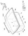
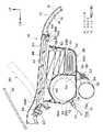
図1には、本実施形態に係る助手席用エアバッグ装置18の全体斜視図が示されている。また、図2には、助手席用エアバッグ装置18が組み込まれたインストルメントパネル10の外観斜視図が示されている。さらに、図3には、組付状態の助手席用エアバッグ装置18の縦断面構造が示されている。 FIG. 1 is an overall perspective view of a passenger
これらの図に示されるように、インストルメントパネル10は、車室内側に配置されかつ軟質樹脂材料によって構成されたインパネ表皮12と、このインパネ表皮12に対して所定の間隔をあけて配置されかつ硬質樹脂材料によって構成されたインパネ基材14と、これらのインパネ表皮12とインパネ基材14との間に充填されたウレタン発泡による発泡層16と、によって構成されている。 As shown in these drawings, the
一方、助手席用エアバッグ装置18は、インストルメントパネル10における助手席側頂部に配置されたエアバッグドア20と、このエアバッグドア20の裏面側に配設された本体部22と、によって構成されている。 On the other hand, the passenger
具体的に説明すると、インパネ基材14における助手席側の頂部所定位置には略矩形状の開口24が形成されており、この開口24の略車両下方側に本体部22が配設されている。本体部22は、前壁部26A、後壁部26B、一対の側壁部26C、底壁部26D、及び傾斜壁部26Eによって略箱体形状に形成された金属製のモジュールケース26を備えている。 More specifically, a substantially
モジュールケース26の底壁部26Dの裏面の両サイドには、中央部にボルト挿通孔が形成された一対の取付ブラケット30が固着されている。これに対応して、インストルメントパネル10の内方側に略車両幅方向を長手方向として配置された高強度のインパネリインフォース32には、ウエルドナット33が溶着された一対の取付ブラケット34が形成されている。そして、インパネリインフォース32側の取付ブラケット34にモジュールケース26側の取付ブラケット30を対応させて、固定ボルト36をウエルドナット33に螺合させることにより、モジュールケース26がインパネリインフォース32に固定されている。 A pair of
上述したモジュールケース26の内部前方側には、略円柱形状のインフレータ38が配設されている。インフレータ38の構成の一例について簡単に説明すると、インフレータ38の周壁部には複数のガス噴出孔(図示省略)が形成されている。また、インフレータ38の内部には、後述するスクイブ70に所定電流が通電されることにより着火する着火剤と、この着火剤が着火されることによりガス発生剤に火炎を伝播する伝火剤と、燃焼することにより大量のガスを発生するガス発生剤と、燃焼後のガス発生剤の砕片の除去等を行うフィルタ等が収容されている。なお、後述するスクイブ70との関係では上記ガス発生剤封入タイプのインフレータ38を用いるのが好ましいが、構成によっては圧縮ガスが封入されたボトルタイプのインフレータを適用することも可能である。 A substantially
また、モジュールケース26の内部後方側には、所定の折り畳み方(蛇腹折り、ロール折り等)で折り畳まれたエアバッグ40が配設されている。なお、エアバッグ40の端末部は、狭幅なリテーナ50を介してリベット等の固定具52でモジュールケース26の上端部に固定されている。また、インフレータ38とエアバッグ40との間には、インフレータ38から噴出されたガスを整流するための複数の開口部(図示省略)が形成されたディフューザ54が配設されている。 Further, an
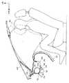
一方、図3に示されるように、助手席用エアバッグ装置18の本体部22を閉塞するエアバッグドア20は、ウインドシールドガラス42に対向して配置されている。より具体的には、エアバッグドア20は、車室内側に配置されかつインパネ表皮12の一部でもあるドア表皮44(なお、区別するために符号のみ変える)と、このドア表皮44に対して所定の間隔をあけて配置され硬質樹脂製かつ略矩形状とされたドア基材46(図1も参照)と、これらのドア表皮44とドア基材46との間に充填されインストルメントパネル10の発泡層16の一部でもある発泡層48(なお、区別するために符号のみ変える)と、によって構成されている。 On the other hand, as shown in FIG. 3, the
上述したドア基材46の周縁部には略車両下方側へ下がる段差部46Aが一体に形成されており、これに対応してインパネ基材14の開口24の周縁部には上向きに鉤状となるように形成された鉤状部14Aが一体に形成されている。段差部46Aと鉤状部14Aとは相互に当接されており、その外周側にインパネ表皮12とドア表皮44との境界を画定する断面U字状の表皮開裂部56が配置されている。なお、表皮開裂部56は、平面視で略コ字形に形成されている(図2参照)。 A
また、ドア基材46の前端部には、狭幅で略車両幅方向を長手方向とする取付部46Bが一体に形成されている。この取付部46Bはインパネ基材14における開口24の周縁前部の上面に当接され、この状態でボルト58及びナット60により開口24の周縁前部に固定されている。 A mounting
ここで、上述したインフレータ38の外周部には、軸直角方向からスクイブ(点火装置)70が取り付けられている。点火装置70は、図示しないコンソールボックス下方等に配設されたセンタコントロールユニットと接続されている。また、センタコントロールユニットは、車両前部両側等に配設され車両前部への所定の高荷重作用状態(車両急減速状態)を検出するエアバッグセンサ(図示省略)と接続されている。 Here, a squib (ignition device) 70 is attached to the outer peripheral portion of the inflator 38 from the direction perpendicular to the axis. The
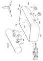
図5に示されるインフレータ38Aはスクイブ70を1個使用するシングル構造のインフレータであり、図6に示されるインフレータ38Bはスクイブ70を2個使用するデュアル構造(二段階出力型)のインフレータである。 The
スクイブ70は略円柱形状を成しており、大径部70Aと小径部70Bを備えている。大径部70Aの外周面には、固定手段の一方を構成する雄ねじ72が形成されている。また、小径部70Bの軸芯部からは配線74が引き出されている。 The
図6に示されるように、デュアル構造のインフレータ38Bでは、一対のスクイブ70が軸方向に所定の間隔Tをあけて配設されている。これに対応して、モジュールケース26の傾斜壁部26Eには、同一の間隔Tで一対の挿通孔76が形成されている。各挿通孔76の内径はスクイブ70の大径部70Aの外径と同一に設定されている。そして、インフレータ38Bをモジュールケース26の内側へ入れて一対のスクイブ70を一対の挿通孔76内へ各々挿通させた後、モジュールケース26の外側から固定手段の他方を構成するナット78をスクイブ70の雄ねじ72に螺合させることにより、インフレータ38Bがモジュールケース26の傾斜壁部26Eの内側に固定される構成である。 As shown in FIG. 6, in the
一方、図5に示されるように、シングル構造のインフレータ38Aでは、単一のスクイブ70が軸方向の所定位置に配設されており、当該スクイブ70からインフレータ38Aの軸方向に一定の間隔Tをあけて位置決め部材としての円柱形状の位置決めピン80が溶接により取り付けられている。位置決めピン80の外径はスクイブ70の大径部70Aの外径と同一に設定されており、又位置決めピン80の外周部には雄ねじ82が形成されている。なお、スクイブ70はインフレータ38Aの周壁部を貫通した状態で配置されるが、位置決めピン80はインフレータ38Aの外周面に溶接で固着されているのみである(即ち、インフレータ38Aの周壁部に孔は形成していない)。そして、インフレータ38Aをモジュールケース26の内側へ入れて一対のスクイブ70と位置決めピン80とを一対の挿通孔76内へそれぞれ挿通させた後、ナット78をスクイブ70の雄ねじ72と位置決めピン80の雄ねじ82とにそれぞれ螺合させることにより、インフレータ38Aがモジュールケース26の傾斜壁部26Eの内側に固定される構成である。 On the other hand, as shown in FIG. 5, in the
すなわち、本実施形態では、シングル構造のインフレータ38A及びデュアル構造のインフレータ38Bのいずれであっても、同一のモジュールケース26が使用されるようになっている。 In other words, in the present embodiment, the
(本実施形態の作用・効果)
次に、本実施形態の作用並びに効果について説明する。(Operation and effect of this embodiment)
Next, the operation and effect of this embodiment will be described.
車両前部への所定の高荷重作用時、即ち車両急減速時になると、当該車両急減速状態が図示しないエアバッグセンサによって検出される。これにより、センタコントロールユニットからインフレータ38のスクイブ70に所定電流が通電される。このため、インフレータ38が作動して、当該インフレータ38のガス噴出孔からガスが噴出される。噴出されたガスはディフューザ54によって整流されてから折り畳み状態のエアバッグ40内へ流入され、当該エアバッグ40を膨張させる。そして、エアバッグ40の膨張圧が所定圧に達すると、エアバッグドア20が表皮開裂部56から破断して、ウインドシールドガラス42側へ向けて片開きに展開される。これにより、エアバッグ40が助手席側へ向けて膨出される。なお、このとき、エアバッグドア20とモジュールケース26とを連結している図示しないストラップが伸張し、これによりエアバッグドア20の展開角度が規制される。その結果、エアバッグドア20とウインドシールドガラス42との干渉が防止される。 When a predetermined high load is applied to the front of the vehicle, that is, when the vehicle suddenly decelerates, the vehicle suddenly decelerated state is detected by an airbag sensor (not shown). As a result, a predetermined current is applied to the
また、上述した助手席用エアバッグ装置18に搭載されたインフレータ38がシングル構造のインフレータ38Aである場合には、単一のスクイブ70に通電され、インフレータ38Aから所定容量のガスが噴出される。これにより、エアバッグ40が所定の展開形状に膨張される(図4の実線図示状態参照)。 When the inflator 38 mounted on the
一方、助手席用エアバッグ装置18に搭載されたインフレータ38がデュアル構造のインフレータ38Bである場合には、エアバッグ40の展開制御がなされる。 On the other hand, when the inflator 38 mounted on the
すなわち、低速で衝突したような場合(軽衝突時)には、一方のスクイブ70のみに通電され、インフレータ38Bの言わば第一段目のみが作動される。これにより、所定容量のガスがエアバッグ40内へ流入され、第1の展開形状(図4の実線図示状態)となる。 That is, when a collision occurs at a low speed (light collision), only one
一方、高速で衝突したような場合(軽衝突時以外の衝突時)には、最初に一方のスクイブ70に通電され、所定容量のガスがエアバッグ40内へ流入される。続いて、他方のスクイブ70に通電されて、第1段目よりも少なめの容量のガスがエアバッグ40内へ時間遅れを生じて流入される。これにより、エアバッグ40内の膨張圧が一定の膨張圧以上である状態を持続させて、乗員に作用する衝撃を長時間に亘って緩和する(図4の二点鎖線図示状態参照)。 On the other hand, when a collision occurs at high speed (when a collision other than a light collision occurs), one of the
なお、デュアル構造のインフレータ38Bの展開制御は上記の如く衝突速度に基づいて行ってもよいし、助手席に着座した乗員が大人か子供かといった体格差に基づいて行ってもよい。体格差の検出は、一例として、フロントシートのシートポジションから検出される。 The deployment control of the dual structure inflator 38B may be performed based on the collision speed as described above, or may be performed based on a physique difference such as whether the passenger seated in the passenger seat is an adult or a child. The physique difference is detected from the seat position of the front seat as an example.
ここで、本実施形態に係る助手席用エアバッグ装置18では、デュアル構造のインフレータ38Bの場合には、当該インフレータ38Bの外周部に所定の間隔Tをあけて一対のスクイブ70を軸直角方向(互いに平行)に配設し、シングル構造のインフレータ38Aの場合には、同一間隔Tをあけて単一のスクイブ70と位置決めピン80とを軸直下方向(互いに平行)に配設したので、一対の挿通孔76の形成位置を変更することなく、同一構造のモジュールケース26を共用することができる。 Here, in the passenger-
より詳細に前記効果を説明すると、図7(A)には対比例としてのシングル構造のインフレータ90が示されている。この図に示されるように、インフレータ90の外周部に軸直角方向に突出するようにスクイブ70を固定し、ナット締めによりモジュールケースに固定しようとした場合、ナット締結時にインフレータ90が回転してしまうため、スクイブ70から所定距離離れた箇所に位置決めピン92を立設させておく必要がある。これに伴い、モジュールケースの傾斜壁部には、スクイブ70と位置決めピン92とが挿通可能な径が異なる一対の挿通孔を形成しておくことになる。 The effect will be described in more detail. FIG. 7A shows a
一方、図7(B)には対比例としてのデュアル構造のインフレータ94が示されている。この図に示されるように、デュアル構造のインフレータ94の場合には、前記場合と同様の考え方をすると、インフレータ94の外周部に一対のスクイブ70と位置決めピン92が配設されることになる。従って、デュアル構造のインフレータ94が搭載される場合には、モジュールケースの傾斜壁部には、三箇所に径が異なる挿通孔を形成する必要がある。このため、単純に「スクイブ70+位置決めピン92」によるインフレータのモジュールケースへの組付を採用すると、モジュールケースを製作する際に穴(挿通孔)を打ち分ける必要が生じ、製作の煩雑化、組付工程の煩雑化等を招く。 On the other hand, FIG. 7B shows a
なお補足すると、デュアル構造のインフレータ94の場合には、一対のスクイブ70が軸直角方向に配設されていれば、これらのスクイブ70によってナット締結時のインフレータ94の回転を防止(回り止め)できるとも考えられるが、シングル構造のインフレータ90の場合と同一の考え方を基調としてインフレータを構築する関係で、予備的に位置決めピン92を立設する。 Note that, in the case of the
しかし、本実施形態のように、モジュールケース26の挿通孔76の形成個数を2個とし、デュアル構造のインフレータ94の場合には一対のスクイブ70をそのまま位置決めピンとしても機能させ、シングル構造のインフレータ90の場合には単一のスクイブ70に加えて余剰の挿通孔76の形成位置と重なる位置に同一径寸法の位置決めピン80を新たに後付けすることとすれば、同一構造のモジュールケース26を共用することができる。その結果、本実施形態によれば、助手席用エアバッグ装置18の生産性を向上させることができると共にコスト削減を図ることができる。 However, as in the present embodiment, the number of the insertion holes 76 formed in the
また、本実施形態では、スクイブ70の大径部70Aの外周面及び位置決めピン92の外周面に雄ねじ72、82を形成することとし、ボルトとして機能させることにより固定手段の一翼を担わせることとしたので、別個独立に固定手段を設定する場合に比し、部品点数の削減を図ることができる。その結果、本実施形態によれば、助手席用エアバッグ装置18の構造の簡素化及びコスト削減を図ることができる。 In the present embodiment,
(実施形態の補足説明)
なお、上述した本実施形態では、エアバッグドア20がウインドシールドガラス42側へ展開するトップダッシュタイプの助手席用エアバッグ装置18のエアバッグモジュールの製造方法に対して本発明を適用したが、これに限らず、グローブボックス上部にエアバッグドアが配設される所謂ミッドシップタイプの助手席用エアバッグ装置のエアバッグモジュールの製造方法に対して本発明を適用してもよい。(Supplementary explanation of the embodiment)
In the above-described embodiment, the present invention is applied tothe manufacturing method of the airbag module of the top dash type
また、上述した本実施形態では、助手席用エアバッグ装置18のエアバッグモジュールの製造方法に対して本発明を適用したが、これに限らず、他のエアバッグ装置(例えば、ルーフサイドレールからバックがカーテン状に展開する側面衝突用の頭部保護エアバッグ装置やシートバックの側部に配設されてドアトリムと乗員の側部との間にエアバッグが展開される側面衝突用のサイドエアバッグ装置、ステアリングホイールのホイールパッドに配設される運転席用のエアバッグ装置等)のエアバッグモジュールの製造方法に対して本発明を適用してもよい。In the above-described embodiment, the present invention is applied to themethod of manufacturing the airbag module of the
さらに、上述した本実施形態では、スクイブ70の大径部70Aの外周面に雄ねじ72を形成し、スクイブ70を利用してインフレータ38A、38Bをモジュールケース26に固定する構成を採ったが、請求項1記載の本発明との関係では、固定手段をスクイブ70とは別個独立に設定した構成も含まれる。 Further, in the present embodiment described above, the
また、上述した本実施形態では、スクイブ70が2個設置されるデュアル構造のインフレータ38Bを例にしたが、これに限らず、スクイブ70が3個以上設置される場合でも同様の考え方を適用することができる。 In the above-described embodiment, the dual-structure inflator 38B in which two
さらに、上述した本実施形態では、インフレータ38が円柱形状を成していたが、これに限らず、他の形状を成していてもよい。 Furthermore, in this embodiment mentioned above, although the inflator 38 comprised the column shape, it may comprise not only this but another shape.
また、上述した本実施形態では、スクイブ70及び位置決めピン80をいずれも円柱形状とし、モジュールケース26の傾斜壁部26Eに形成される一対の挿通孔76も同一径寸法の円孔としたが、必ずしも、円形である必要はなく、多角形状のスクイブ、位置決めピン、挿通孔を採用してもよい。 In the present embodiment described above, the
さらに、上述した本実施形態では、位置決めピン80をインフレータ38Bの外周面に溶接により取り付ける構成を採ったが、これに限らず、溶接以外の取付手段を採用してもよい。 Further, in the above-described embodiment, the configuration in which the
また、上述した本実施形態では、モジュールケース26内にディフューザ54を配設したが、必ずしもディフューザ54を備えている必要はない。 In the above-described embodiment, the
さらに、上述した本実施形態では、エアバッグドア20が片開きに展開する構成を採ったが、これに限らず、両開きに展開する構成等、エアバッグドアの展開方法は種々の方法を採用し得る。 Furthermore, in the above-described embodiment, the configuration in which the
また、上述した本実施形態では、エアバッグ40の展開制御につき、一方のスクイブ70を乗員拘束時(衝突時)に作動させ、他方のスクイブ70を大きく遅延させて作動させるようにしたが、これに限らず、乗員の体格差による展開制御も含めて種々の展開制御を採用し得る。 Further, in the present embodiment described above, for the deployment control of the
18 助手席用エアバッグ装置
26 モジュールケース
38 インフレータ
38A シングル構造のインフレータ
38B デュアル構造のインフレータ
40 エアバッグ
70 スクイブ
72 雄ねじ(固定手段)
76 挿通孔
78 ナット(固定手段)
80 位置決めピン(位置決め部材)
82 雄ねじ(固定手段)18 Airbag Device for
76
80 Positioning pin (positioning member)
82 Male thread (fixing means)
Claims (2)
Translated fromJapaneseインフレータ及び折り畳み状態のエアバッグを収容すると共に点火装置の突出部分が挿通可能な複数の挿通孔が形成されたモジュールケースと、
インフレータをモジュールケースに固定する固定手段と、
を含んで構成されたエアバッグモジュール構造に適用されるエアバッグモジュールの製造方法であって、
挿通孔の形成個数が点火装置の配設個数と同数の場合には、当該点火装置の突出部分を対応する挿通孔内へそれぞれ挿通させた状態で固定手段を使ってインフレータをモジュールケースに固定し、
挿通孔の形成個数が点火装置の配設個数よりも多い場合には、インフレータにおける余剰となった挿通孔と対応する位置に当該挿通孔内へ挿通可能な位置決め部材を取り付けた上で、当該点火装置の突出部分及び位置決め部材を対応する挿通孔内へそれぞれ挿通させた状態で固定手段を使ってインフレータをモジュールケースに固定した、
ことを特徴とするエアバッグモジュールの製造方法。A single or a plurality of ignition devices that are arranged in a state of partially protruding from an inflator that generates gas by operation and inflates a folded airbag, and that activates the inflator in the event of a collision;
A module case that accommodates the inflator and the folded airbag and has a plurality of insertion holes into which the protruding portion of the ignition device can be inserted;
Fixing means for fixing the inflator to the module case;
Anairbag module manufacturing method applied to an airbag module structure configured to include:
When the number of insertion holes formed is the same as the number of ignition devices, the inflator is fixed to the module case using fixing means with the protruding portions of the ignition devices inserted into the corresponding insertion holes. ,
When the number of insertion holes formed is larger than the number of ignition devices, a positioning member that can be inserted into the insertion hole is attached to a position corresponding to the excess insertion hole in the inflator, and then the ignition The inflator was fixed to the module case using a fixing means in a state where the protruding portion of the device and the positioning member were respectively inserted into the corresponding insertion holes,
Amethod of manufacturing anair bag module .
ことを特徴とする請求項1記載のエアバッグモジュールの製造方法。The protruding portion of the ignition device and the positioning member also serve as the fixing means.
Themethod for manufacturing an airbag module according to claim 1.
Priority Applications (1)
| Application Number | Priority Date | Filing Date | Title |
|---|---|---|---|
| JP2004254489AJP4301123B2 (en) | 2004-09-01 | 2004-09-01 | Manufacturing method of airbag module |
Applications Claiming Priority (1)
| Application Number | Priority Date | Filing Date | Title |
|---|---|---|---|
| JP2004254489AJP4301123B2 (en) | 2004-09-01 | 2004-09-01 | Manufacturing method of airbag module |
Publications (2)
| Publication Number | Publication Date |
|---|---|
| JP2006069337A JP2006069337A (en) | 2006-03-16 |
| JP4301123B2true JP4301123B2 (en) | 2009-07-22 |
Family
ID=36150408
Family Applications (1)
| Application Number | Title | Priority Date | Filing Date |
|---|---|---|---|
| JP2004254489AExpired - Fee RelatedJP4301123B2 (en) | 2004-09-01 | 2004-09-01 | Manufacturing method of airbag module |
Country Status (1)
| Country | Link |
|---|---|
| JP (1) | JP4301123B2 (en) |
Families Citing this family (2)
| Publication number | Priority date | Publication date | Assignee | Title |
|---|---|---|---|---|
| DE102008026795A1 (en)* | 2008-06-02 | 2009-12-10 | Takata-Petri Ag | airbag module |
| JP5323191B2 (en)* | 2009-06-23 | 2013-10-23 | オートリブ ディベロップメント エービー | Airbag device |
- 2004
- 2004-09-01JPJP2004254489Apatent/JP4301123B2/ennot_activeExpired - Fee Related
Also Published As
| Publication number | Publication date |
|---|---|
| JP2006069337A (en) | 2006-03-16 |
Similar Documents
| Publication | Publication Date | Title |
|---|---|---|
| JP5679075B2 (en) | Automotive airbag system | |
| US6712385B2 (en) | Dent and vibration resistant rigid knee airbag | |
| US6808198B2 (en) | Pillar-mounted frontal airbag | |
| US6976706B2 (en) | Inflatable bolster with decorative front panel and expandable metal rear panel | |
| JP6265190B2 (en) | Car occupant protection device | |
| US8465049B2 (en) | Airbag and airbag device | |
| US11518335B2 (en) | Driver side airbag module | |
| JP2004276899A (en) | Inflatable restraint module | |
| KR20190066355A (en) | Curtain airbag of vehicle | |
| JP4301123B2 (en) | Manufacturing method of airbag module | |
| JP2007050847A (en) | Side impact airbag device | |
| JP2001163161A (en) | Head protection airbag device | |
| KR20020037201A (en) | connecting device of air bag modul for automobiles | |
| JP2004284423A (en) | Airbag device for rear end collision of vehicle | |
| KR100938328B1 (en) | Car Curtain Airbag | |
| JP2010264788A (en) | Knee airbag device for vehicle | |
| JP5725046B2 (en) | Knee lateral restraint airbag device | |
| KR101081701B1 (en) | Curtain Air Bag for Automobile | |
| JPH0542855A (en) | Air bag structure of automobile | |
| KR20030063738A (en) | The roof air-bag for automobile | |
| KR100510359B1 (en) | Driver air-bag for a vehicle | |
| KR100750403B1 (en) | Side airbag of car | |
| KR100512856B1 (en) | Double driver air-bag for a vehicle | |
| KR100417383B1 (en) | connecting device for airbag module of passenger | |
| KR200176767Y1 (en) | Front passenger airbags |
Legal Events
| Date | Code | Title | Description |
|---|---|---|---|
| A621 | Written request for application examination | Free format text:JAPANESE INTERMEDIATE CODE: A621 Effective date:20061025 | |
| A977 | Report on retrieval | Free format text:JAPANESE INTERMEDIATE CODE: A971007 Effective date:20081225 | |
| A131 | Notification of reasons for refusal | Free format text:JAPANESE INTERMEDIATE CODE: A131 Effective date:20090106 | |
| A521 | Written amendment | Free format text:JAPANESE INTERMEDIATE CODE: A523 Effective date:20090306 | |
| TRDD | Decision of grant or rejection written | ||
| A01 | Written decision to grant a patent or to grant a registration (utility model) | Free format text:JAPANESE INTERMEDIATE CODE: A01 Effective date:20090331 | |
| A01 | Written decision to grant a patent or to grant a registration (utility model) | Free format text:JAPANESE INTERMEDIATE CODE: A01 | |
| FPAY | Renewal fee payment (event date is renewal date of database) | Free format text:PAYMENT UNTIL: 20120501 Year of fee payment:3 | |
| A61 | First payment of annual fees (during grant procedure) | Free format text:JAPANESE INTERMEDIATE CODE: A61 Effective date:20090413 | |
| FPAY | Renewal fee payment (event date is renewal date of database) | Free format text:PAYMENT UNTIL: 20120501 Year of fee payment:3 | |
| FPAY | Renewal fee payment (event date is renewal date of database) | Free format text:PAYMENT UNTIL: 20130501 Year of fee payment:4 | |
| FPAY | Renewal fee payment (event date is renewal date of database) | Free format text:PAYMENT UNTIL: 20130501 Year of fee payment:4 | |
| LAPS | Cancellation because of no payment of annual fees |