JP4298460B2 - Panel speaker - Google Patents
Panel speakerDownload PDFInfo
- Publication number
- JP4298460B2 JP4298460B2JP2003346541AJP2003346541AJP4298460B2JP 4298460 B2JP4298460 B2JP 4298460B2JP 2003346541 AJP2003346541 AJP 2003346541AJP 2003346541 AJP2003346541 AJP 2003346541AJP 4298460 B2JP4298460 B2JP 4298460B2
- Authority
- JP
- Japan
- Prior art keywords
- diaphragm
- frame
- driver
- edge
- outer peripheral
- Prior art date
- Legal status (The legal status is an assumption and is not a legal conclusion. Google has not performed a legal analysis and makes no representation as to the accuracy of the status listed.)
- Expired - Lifetime
Links
Images


Landscapes
- Diaphragms For Electromechanical Transducers (AREA)
Description
Translated fromJapaneseこの発明は、音響機器の一種である平板状のパネルスピーカに関する。 The present invention relates to a flat panel speaker which is a kind of acoustic equipment.
パネル型のスピーカとしては、例えば特開2003−153361,特開2002−176685,特表2002−530902,特開2001−61194等が存在する。 As panel type speakers, there are, for example, Japanese Patent Application Laid-Open Nos. 2003-153361, 2002-176665, 2002-530902, and Japanese Patent Application 2001-61194.
これらのパネル型のスピーカは横長の矩形の枠状のフレーム内に平板状の振動板を配置するなどし、振動板に、印刷されたシートを貼ったり、画像やその他の視覚情報を表示させるように構成している。 These panel-type speakers have a flat diaphragm arranged in a horizontally long rectangular frame, so that a printed sheet is pasted on the diaphragm, and images and other visual information are displayed. It is configured.
これらのパネル型スピーカは本来のスピーカの機能である可聴情報伝達機能に加え、視覚情報表示機能も併せもたせるメリットがあるが、振動板が透明なものではないので、スピーカの背後を見通すことはできず、例えばPDP等の機器の前面に配置して映像をスピーカの前面から見るというような使用はできないものである。 These panel-type speakers have the advantage of having a visual information display function in addition to the audible information transmission function that is the function of the original speaker, but because the diaphragm is not transparent, the back of the speaker cannot be seen. For example, it is not possible to use the camera such as a PDP or the like placed on the front face of a device and viewing an image from the front face of the speaker.
最近、各種映像機器が普及してきており、スピーカもこれらと組み合わせた多様な使用形態に対応するものが望まれる一方、設置環境に合わせた多様な仕様や意匠性なども求められるようになってきた。 Recently, various types of video equipment have become widespread, and while it is desirable for speakers to be compatible with a variety of usage forms combined with these, a variety of specifications and design features tailored to the installation environment have also been required. .
パネルスピーカの振動板自体を透明なものにすれば、これらの要求に対応して設置の自由度を向上させたり、意匠性のすぐれたインテリアとしての効果を期待できる。 If the diaphragm of the panel speaker itself is made transparent, it is possible to improve the degree of freedom of installation in response to these requirements, and to expect the effect as an interior with excellent design.
振動板が透明であることによる使用方法の多様化に併せて、小型、薄型であっても優れた音響再生も両立させること、さらにこれを安価に製造することが期待される。 Along with the diversification of usage methods due to the transparent diaphragm, it is expected to achieve both excellent sound reproduction even if it is small and thin, and to manufacture it at low cost.
パネル型のスピーカの振動板を透明としたものとしては、特開昭62−73898,特開平11−288040,特開2002−252895等が存在する。
特開昭62−73898におけるスピーカは、テレビジョン受像機の前面に配置したり、カーステレオ用のスピーカとして窓ガラスに装着可能にしてあるが、振動板をエッジを介して湾曲状に保持し、かつ振動板の端部を振動板面にほぼ平行な方向に駆動する構成であるため、スピーカに厚みが生じ、軽量・コンパクト化に限界があった。 The speaker in JP-A-62-73898 is arranged on the front of a television receiver or can be attached to a window glass as a speaker for a car stereo, but the diaphragm is held in a curved shape via an edge, Further, since the end portion of the diaphragm is driven in a direction substantially parallel to the diaphragm surface, the speaker is thick, and there is a limit to light weight and compactness.
また、特開平11−288040は、スピーカの振動板は透明であるものの、スピーカに映像照射器が組み合わされているため、スピーカ装置が大型化し、また、コスト高となるとともに、スピーカは透明基板に透明圧電体、透明ホログラム素子等を積層した構成としているため、振動体にも厚みが生じ、かつ重くなり、またこの部分もコスト高を招来する、という課題があった。 In Japanese Patent Laid-Open No. 11-288040, although the diaphragm of the speaker is transparent, since the image irradiator is combined with the speaker, the size of the speaker device is increased, the cost is increased, and the speaker is mounted on a transparent substrate. Since the transparent piezoelectric body, the transparent hologram element, and the like are laminated, the vibration body is thick and heavy, and there is a problem that this portion also increases the cost.
また、特開2002−252895においては、振動板背面全面が開放された状態で、しかも振動板は部分的に設けたエッジで支持されている構造であるため、良好な音響再生ができないという課題があった。 Further, in Japanese Patent Laid-Open No. 2002-252895, since the diaphragm has a structure in which the entire rear surface of the diaphragm is opened, and the diaphragm is supported by a partially provided edge, there is a problem that good sound reproduction cannot be performed. there were.
この発明は上記のことに鑑み提案されたもので、その目的とするところは、振動板を透明で見通し可能なものとすることによって使用形態の自由度を高めるとともに、小型、薄型でかつ良好な音響再生ができるパネルスピーカを、簡易構成で安価に提供することにある。 The present invention has been proposed in view of the above, and an object of the present invention is to increase the degree of freedom of use by making the diaphragm transparent and visible, and to be small, thin and good. The object is to provide a panel speaker capable of sound reproduction at a low cost with a simple configuration.
請求項1記載の発明は、平面板状の透明な振動板2と、この振動板2の周囲に設けられ、少なくとも振動板2より重量のある材質からなり、かつ内側部分が大きな窓となっており、前記振動板の表裏面は開放される枠状のフレーム1とを備え、このフレーム1はバックキャビティとしてのほぼ密閉状の中空部7を有し、この中空部7内に振動板駆動用のドライバ8および枠状のエッジ17が設けられ、この中空部7内に前記振動板2の外周部2aが配設され、前記ドライバ8に接続されるとともに、前記外周部2aのほぼ全周が前記エッジ17に固着され、前記振動板2が前記エッジ17を介して支持され、前記フレーム1内に設けられたドライバ8は前記振動板2の振動の節に対し、少なくとも一つの次数の節を通り、かつ少なくとも一つの線対称配置を形成するような位置に配設された構成とし、上記目的を達成している。First aspect of the present invention, a flat plate shaped
請求項2記載の発明は、請求項1記載のパネルスピーカにおいて、前記振動板2を支持するエッジ17の前面側は振動を阻害しないように空間部が設けられるとともに、振動板2の前面側と前面枠体6との間にも空間部が設けられ、かつ前記ドライバ8の平面形状は横長のトラック形状に形成され、トラック形状の振動体12が前記振動板外周部2aの背面に接続されることを特徴としている。According to a second aspect of the present invention, inthe panel speaker according to the first aspect, the front side of the edge 17 supporting the
請求項1記載の発明によれば、額縁状のフレーム1に平面板状であって透明の振動板2を設け、この振動板2の外周部2aをフレーム1に設けたほぼ密閉状の中空部7内で支持し、かつ中空部7内に設けたドライバ8によって駆動するようにし、振動板2は平面板状であるため、パネルスピーカの厚みを薄くすることができ、小型、軽量化を達成でき、かつ振動板2は透明で見通し可能なため、配置の自由度が向上しインテリア的にも良好で、また他のTV等の映像機器類と組み合わせ一体化して使用することもでき、使用形態の多様化に対応し得る。 According to the first aspect of the present invention, the frame-
また、中空部7はバックキャビティとして機能し、さらに振動板2の外周部2aのほぼ全域が枠状のエッジ17に固着されこのエッジ17を介してフレームに取り付けられていることによって、良好な音響再生を達成している。また、フレーム1は振動板2よりも重量のある材質により構成したため、振動板が比較的重いものであって振動する際の反作用が大きくても、この反作用の影響を防いで安定した音響再生をすることができる。 Further, the
また、ドライバ8は振動板2の振動の節に対し、少なくとも一つの次数の振動の節の位置に設け、また、ドライバ8をトラック形状とし、振動板を能率良く駆動することができ、さらに少なくとも一つの線対称配置を形成するような位置に設けたことにより、良好な周波数特性を得ることができる。The
以下、図面に沿って本発明の実施例を説明する。 Embodiments of the present invention will be described below with reference to the drawings.
[実施の形態1]
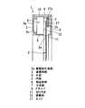
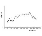
図1(a)は本発明の一実施例の正面図、同図(b)はそのA−A線断面図、図2は図1(b)中A部の拡大図、図3は本発明で用いられるドライバの概略内部構造図、図4は図1の状態から前面枠体、振動板を取り除いた正面図、図5は周波数特性図を示す。[Embodiment 1]
1A is a front view of an embodiment of the present invention, FIG. 1B is a cross-sectional view taken along the line AA of FIG. 2, FIG. 2 is an enlarged view of a portion A in FIG. 1B, and FIG. 4 is a schematic internal structure diagram of the driver used in FIG. 4, FIG. 4 is a front view in which the front frame and the diaphragm are removed from the state of FIG. 1, and FIG. 5 is a frequency characteristic diagram.
まず、図1において、1はフレーム、2は透明の材質からなる平面板状の振動板である。 First, in FIG. 1, 1 is a frame, and 2 is a flat plate-like diaphragm made of a transparent material.
フレーム1は枠状をなし、材質としては、例えばアルミ材のような少なくとも振動板2の重量よりも大きな重量を有する材質が用いられる。 The
このフレーム1は正面から見て額縁状の矩形をなし、内側部分が大きな窓となっており、ドライバ8を設置する中空部7を有する背面枠体3と、その中空部7を塞ぐように組み合わされる前面枠体6から構成されている。本実施例のフレーム形状は矩形としたが、必ずしも矩形に限定されるものではない。 The
振動板2はフレーム形状にほぼ対応した形状をなし、その大きさはフレーム1より若干小をなし、材質としては例えば厚さ0.9mmの透明な平面板状のアクリル板を用いると好ましいが、その他としてポリカーボネート等の、プラスチック製のもの、あるいはガラス等を用いても良い。 The
フレーム1の背面枠体3は、図1(b)および図2に示すように、外側の外板4および内側の内板5を有し、前面側に前面枠体6が組み合わせられ、これらによって内部にほぼ密閉状の中空部7が形成されている。 As shown in FIG. 1B and FIG. 2, the
この中空部7は振動板2を駆動するためのドライバ8や、振動板2の外周部2aを支持する例えば発泡ゴムからなるエッジ17が設けられているとともに、中空部7は音響効果を得るためのバックキャビティとして機能する。 The
ドライバ8は、図3に示すように、カップ状のヨーク9と、これより外形が大きいフレーム10とを備え、図2に示すように、ヨーク9の端部9aは背面枠体3の内壁面に形成された凹所3cに位置決め固定され、かつフレーム10の外周面の上下部分は外板4および内板5によって直接またはスペースを介し間接的に挟持される。したがって、ドライバ8は外板4、内板5によって外部から見えることはなく、外観的に良好となっている。 As shown in FIG. 3, the
内板5の前面側の端部5aと前面枠体6との間には空隙11が形成され、この空隙11を介して振動板2の外周部2a側が中空部7内に導入され、振動板2の外周部前面側はエッジ17によって振動可能に支持される。 A
基端17aが外板4の内側に固定されたエッジ17は枠状をなし、振動板2の外周部背面全体を支持するように構成されている。 The edge 17 whose
また、振動板2の外周部背面はドライバ8の振動体12に結合されている。 The rear surface of the outer peripheral portion of the
ドライバ8の内部構造の一例としては、図3に示すように、カップ状のヨーク9を有し、このヨーク9の内部に短円柱状のマグネット13が設けられ、このマグネット13の端面には円板状のポールピース14が設けられ、ポールピース14の外周面とヨーク9の開口部との間に磁気ギャップ15が形成され、これらによって磁気回路が構成され、磁気ギャップ15にボイスコイルからなる振動体12の一端部が配置され、振動体12の他端部側は振動板2の外周部2aの前面に接続されている。 As an example of the internal structure of the
振動体12はフレーム10内の開口部分に設けられたダンパ16によって支持されている。 The vibrating
なお、図2に示すように、振動板2を支持するエッジ17の前面側はエッジ17の振動を阻害しないように空間部が設けられ、また、振動板2の前面側と前面枠体6との間にも空間部が設けられている。 As shown in FIG. 2, a space is provided on the front side of the edge 17 that supports the
図4はフレーム1の前面枠体6および振動板2を取り除いた内部構造を示す正面図で、この図からわかるように、ドライバ8の平面形状は横長のトラック形状に形成され、背面枠体3の短辺側のほぼ中央部にそれぞれ設けられ、トラック形状の振動体12が振動板外周部2aの背面に接続される。
FIG. 4 is a front view showing the internal structure of the
このドライバ8は、平面板状の少なくとも一つの線対称配置を形成するような位置に配設されている。 The
動作にあたっては各ドライバ8に音声信号を印加することにより、それに応じて振動板12が振動し、その振動が平面板状の振動板2に伝達される。 In operation, an audio signal is applied to each
この際、フレーム1内のほぼ密閉状の中空部7はバックキャビティとして機能することにより、良好な周波数特性が得られ、かつこの場合、振動板2が接続されたエッジ17近傍の裏面から前面側へ音が回り込み表裏の音が干渉し合って音の劣化を招くことが防止され、良好な音響再生を実現し得る。 At this time, the substantially hermetically sealed
図5は本発明の周波数特性図を示す。 FIG. 5 shows a frequency characteristic diagram of the present invention.
また、図示例ではパネルスピーカを縦型に配置した例について示しているが、使用にあたり、横型に配置して使用し得ることは云うまでもない。 In the illustrated example, an example in which the panel speakers are arranged vertically is shown. Needless to say, however, the speakers can be arranged horizontally to be used.
この場合、ステレオ信号の左チャンネル信号を左側のドライバ8に、右チャンネル信号を右側のドライバ8に入力することにより、ステレオ再生を行うことができる。 In this case, stereo reproduction can be performed by inputting the left channel signal of the stereo signal to the
[実施の形態2]
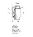
図6は本発明の他の実施例を示す。[Embodiment 2]
FIG. 6 shows another embodiment of the present invention.
この実施例では、背面枠体3の各長辺側にそれぞれ2個のドライバ8を設けてあり、第1実施例にては各短辺側にそれぞれ1個のドライバ8を、短辺に平行なほぼ中央の線に対して線対称な配置としているのに対し、短辺に平行な中心線、長辺に平行な中心線のいずれに対しても線対称をなす配置となっている。 In this embodiment, two
他の構成は前述の実施例とほぼ同様である。 Other configurations are almost the same as those of the above-described embodiment.
なお、図示例では横型のパネルスピーカを示したが、これを縦型にして使用しても良いことは勿論である。 In the illustrated example, a horizontal panel speaker is shown, but it is needless to say that it may be used in a vertical type.
1 フレーム
2 平面板状振動板
2a 振動板外周部
3 背面枠体
3c 凹所
4 外板
5 内板
5a 内板端部
6 前面枠体
7 中空部
8 ドライバ
9 ヨーク
9a ヨーク端部
10 フレーム
11 空隙
12 振動体
13 マグネット
14 ポールピース
15 磁気キャップ
16 ダンパ
17 エッジ
17a エッジ基部DESCRIPTION OF
Claims (2)
Translated fromJapanesePriority Applications (1)
| Application Number | Priority Date | Filing Date | Title |
|---|---|---|---|
| JP2003346541AJP4298460B2 (en) | 2003-10-06 | 2003-10-06 | Panel speaker |
Applications Claiming Priority (1)
| Application Number | Priority Date | Filing Date | Title |
|---|---|---|---|
| JP2003346541AJP4298460B2 (en) | 2003-10-06 | 2003-10-06 | Panel speaker |
Publications (2)
| Publication Number | Publication Date |
|---|---|
| JP2005117217A JP2005117217A (en) | 2005-04-28 |
| JP4298460B2true JP4298460B2 (en) | 2009-07-22 |
Family
ID=34539432
Family Applications (1)
| Application Number | Title | Priority Date | Filing Date |
|---|---|---|---|
| JP2003346541AExpired - LifetimeJP4298460B2 (en) | 2003-10-06 | 2003-10-06 | Panel speaker |
Country Status (1)
| Country | Link |
|---|---|
| JP (1) | JP4298460B2 (en) |
Families Citing this family (5)
| Publication number | Priority date | Publication date | Assignee | Title |
|---|---|---|---|---|
| JP2008219202A (en) | 2007-02-28 | 2008-09-18 | National Institute Of Information & Communication Technology | Sound vibration playback device |
| JP5223439B2 (en) | 2007-05-28 | 2013-06-26 | ソニー株式会社 | Semiconductor light emitting device |
| WO2012157691A1 (en) | 2011-05-17 | 2012-11-22 | 株式会社村田製作所 | Planar speaker and av device |
| KR101944676B1 (en)* | 2018-08-06 | 2019-02-28 | 주식회사 엠소닉 | Interior speaker |
| KR102074823B1 (en)* | 2018-12-10 | 2020-03-02 | 주식회사 엠소닉 | Interior speaker |
Family Cites Families (3)
| Publication number | Priority date | Publication date | Assignee | Title |
|---|---|---|---|---|
| JPH0659117B2 (en)* | 1987-03-25 | 1994-08-03 | 松下電器産業株式会社 | Speaker |
| JP3858412B2 (en)* | 1998-01-23 | 2006-12-13 | ソニー株式会社 | Filter device |
| TR200100136T2 (en)* | 1998-07-03 | 2001-06-21 | New Transducers Limited | Panel-shaped resonant speaker |
- 2003
- 2003-10-06JPJP2003346541Apatent/JP4298460B2/ennot_activeExpired - Lifetime
Also Published As
| Publication number | Publication date |
|---|---|
| JP2005117217A (en) | 2005-04-28 |
Similar Documents
| Publication | Publication Date | Title |
|---|---|---|
| CN107561753B (en) | Panel vibration type sound display device | |
| JP5314588B2 (en) | Composite speaker, sound image display device, and vehicle acoustic system | |
| JP4861825B2 (en) | Speaker system | |
| KR101817102B1 (en) | Display device for generating sound by panel vibration type | |
| EP1868409B1 (en) | Speaker system | |
| JP6136023B2 (en) | Speaker | |
| EP1617703B1 (en) | Speaker apparatus using display window | |
| JP4519837B2 (en) | Speaker device | |
| EP1800514B1 (en) | Display device comprising a panel acoustic transducer, and transparent panel acoustic transducer | |
| EP3761666B1 (en) | Display appratus | |
| JP2005191746A (en) | Speaker assembly | |
| CN103648071A (en) | Speaker, video device, and mobile information processing device | |
| JPWO2007125569A1 (en) | Speaker device | |
| JP2001061194A (en) | Panel-type loudspeaker | |
| JP2008283350A (en) | Flexible display acoustic device | |
| JP2010166515A (en) | Flat panel loudspeaker, audio/image display, and acoustic system for vehicle | |
| KR102261837B1 (en) | The exciter mounted on a glass and the vehicle thereof | |
| JP2008124738A (en) | Speaker device | |
| JPS6273898A (en) | Speaker | |
| JP4298460B2 (en) | Panel speaker | |
| JP4643626B2 (en) | Speaker device | |
| JP4190938B2 (en) | Panel type speaker | |
| WO2022193716A1 (en) | Projection device and display apparatus | |
| JP2000059879A (en) | Speaker device | |
| JPH11331966A (en) | Panel speaker |
Legal Events
| Date | Code | Title | Description |
|---|---|---|---|
| A621 | Written request for application examination | Free format text:JAPANESE INTERMEDIATE CODE: A621 Effective date:20060926 | |
| A131 | Notification of reasons for refusal | Free format text:JAPANESE INTERMEDIATE CODE: A131 Effective date:20081021 | |
| A521 | Request for written amendment filed | Free format text:JAPANESE INTERMEDIATE CODE: A523 Effective date:20081219 | |
| TRDD | Decision of grant or rejection written | ||
| A01 | Written decision to grant a patent or to grant a registration (utility model) | Free format text:JAPANESE INTERMEDIATE CODE: A01 Effective date:20090414 | |
| A01 | Written decision to grant a patent or to grant a registration (utility model) | Free format text:JAPANESE INTERMEDIATE CODE: A01 | |
| A61 | First payment of annual fees (during grant procedure) | Free format text:JAPANESE INTERMEDIATE CODE: A61 Effective date:20090415 | |
| R150 | Certificate of patent or registration of utility model | Ref document number:4298460 Country of ref document:JP Free format text:JAPANESE INTERMEDIATE CODE: R150 Free format text:JAPANESE INTERMEDIATE CODE: R150 | |
| FPAY | Renewal fee payment (event date is renewal date of database) | Free format text:PAYMENT UNTIL: 20120424 Year of fee payment:3 | |
| FPAY | Renewal fee payment (event date is renewal date of database) | Free format text:PAYMENT UNTIL: 20120424 Year of fee payment:3 | |
| FPAY | Renewal fee payment (event date is renewal date of database) | Free format text:PAYMENT UNTIL: 20130424 Year of fee payment:4 | |
| FPAY | Renewal fee payment (event date is renewal date of database) | Free format text:PAYMENT UNTIL: 20140424 Year of fee payment:5 | |
| S531 | Written request for registration of change of domicile | Free format text:JAPANESE INTERMEDIATE CODE: R313531 | |
| R350 | Written notification of registration of transfer | Free format text:JAPANESE INTERMEDIATE CODE: R350 | |
| R250 | Receipt of annual fees | Free format text:JAPANESE INTERMEDIATE CODE: R250 | |
| R250 | Receipt of annual fees | Free format text:JAPANESE INTERMEDIATE CODE: R250 | |
| R250 | Receipt of annual fees | Free format text:JAPANESE INTERMEDIATE CODE: R250 | |
| R250 | Receipt of annual fees | Free format text:JAPANESE INTERMEDIATE CODE: R250 | |
| R250 | Receipt of annual fees | Free format text:JAPANESE INTERMEDIATE CODE: R250 | |
| R250 | Receipt of annual fees | Free format text:JAPANESE INTERMEDIATE CODE: R250 | |
| R250 | Receipt of annual fees | Free format text:JAPANESE INTERMEDIATE CODE: R250 | |
| EXPY | Cancellation because of completion of term |