JP4298455B2 - Scanning image display device - Google Patents
Scanning image display deviceDownload PDFInfo
- Publication number
- JP4298455B2 JP4298455B2JP2003340789AJP2003340789AJP4298455B2JP 4298455 B2JP4298455 B2JP 4298455B2JP 2003340789 AJP2003340789 AJP 2003340789AJP 2003340789 AJP2003340789 AJP 2003340789AJP 4298455 B2JP4298455 B2JP 4298455B2
- Authority
- JP
- Japan
- Prior art keywords
- scanned
- scanning
- light source
- optical system
- light beam
- Prior art date
- Legal status (The legal status is an assumption and is not a legal conclusion. Google has not performed a legal analysis and makes no representation as to the accuracy of the status listed.)
- Expired - Fee Related
Links
Images


Classifications
- G—PHYSICS
- G02—OPTICS
- G02B—OPTICAL ELEMENTS, SYSTEMS OR APPARATUS
- G02B7/00—Mountings, adjusting means, or light-tight connections, for optical elements
- G02B7/003—Alignment of optical elements
- G—PHYSICS
- G02—OPTICS
- G02B—OPTICAL ELEMENTS, SYSTEMS OR APPARATUS
- G02B27/00—Optical systems or apparatus not provided for by any of the groups G02B1/00 - G02B26/00, G02B30/00
- G02B27/01—Head-up displays
- G02B27/017—Head mounted
- G—PHYSICS
- G02—OPTICS
- G02B—OPTICAL ELEMENTS, SYSTEMS OR APPARATUS
- G02B27/00—Optical systems or apparatus not provided for by any of the groups G02B1/00 - G02B26/00, G02B30/00
- G02B27/01—Head-up displays
- G02B27/017—Head mounted
- G02B27/0172—Head mounted characterised by optical features
- G—PHYSICS
- G02—OPTICS
- G02B—OPTICAL ELEMENTS, SYSTEMS OR APPARATUS
- G02B27/00—Optical systems or apparatus not provided for by any of the groups G02B1/00 - G02B26/00, G02B30/00
- G02B27/01—Head-up displays
- G02B27/017—Head mounted
- G02B27/0176—Head mounted characterised by mechanical features
- G—PHYSICS
- G02—OPTICS
- G02B—OPTICAL ELEMENTS, SYSTEMS OR APPARATUS
- G02B27/00—Optical systems or apparatus not provided for by any of the groups G02B1/00 - G02B26/00, G02B30/00
- G02B27/01—Head-up displays
- G02B27/0101—Head-up displays characterised by optical features
- G02B2027/0123—Head-up displays characterised by optical features comprising devices increasing the field of view
- G—PHYSICS
- G02—OPTICS
- G02B—OPTICAL ELEMENTS, SYSTEMS OR APPARATUS
- G02B26/00—Optical devices or arrangements for the control of light using movable or deformable optical elements
- G02B26/08—Optical devices or arrangements for the control of light using movable or deformable optical elements for controlling the direction of light
- G02B26/10—Scanning systems
- G02B26/105—Scanning systems with one or more pivoting mirrors or galvano-mirrors
Landscapes
- Physics & Mathematics (AREA)
- General Physics & Mathematics (AREA)
- Optics & Photonics (AREA)
- Transforming Electric Information Into Light Information (AREA)
- Mechanical Optical Scanning Systems (AREA)
Description
Translated fromJapanese本発明は、光源からの光束を光走査手段を用いて走査することにより画像を表示する走査型画像表示装置に関し、特に映像信号に基づいて所定の画像を表示する頭部装着型映像表示装置や、デジタルカメラ等の電子式ビューファンダーシステムに関するものである。 The present invention relates to a scanning image display device that displays an image by scanning a light beam from a light source using an optical scanning unit, and more particularly to a head-mounted image display device that displays a predetermined image based on a video signal, The present invention relates to an electronic view funder system such as a digital camera.
現在、頭部装着型映像表示装置やデジタルカメラ等の映像表示装置としては、透過型液晶、反射型液晶、または有機EL素子などのいわゆるフラットパネルと呼ばれる2次元表示素子を使用しているものがある。これら2次元表示素子を接眼光学系と組み合わせ、表示画像を虚像として観察するように構成されたものが数多く提案されている。近年、そのような画像表示装置は、より高精細な画像が要求されている。そのため、フラットパネルディスプレイ上に非常に多くの画素数分の画素を製作しなければならず、画素数が増えた分だけ画素欠陥が増加し易くなる一方で、フラットパネルの大きさに対して、相対的に画素の大きさが小さくなり製造が困難になるなどの問題があった。 Currently, as a head-mounted image display device, a digital camera, or the like, an image display device using a so-called flat panel such as a transmissive liquid crystal, a reflective liquid crystal, or an organic EL element is used. is there. Many proposals have been made to combine these two-dimensional display elements with an eyepiece optical system and observe a display image as a virtual image. In recent years, such image display apparatuses are required to have higher definition images. Therefore, a very large number of pixels must be manufactured on the flat panel display, and pixel defects are likely to increase as the number of pixels increases. There has been a problem that the size of the pixel is relatively small and the manufacture becomes difficult.
一方、2次元映像表示素子を用いず走査手段を使った表示装置が、米国特許5,467,104号などにて開示・提案されている。米国特許5,467,104号は、RGBの光を水平方向と垂直方向に走査し、光学系を介して網膜上に直接画像を形成する技術を示している。 On the other hand, a display device using scanning means without using a two-dimensional image display element is disclosed and proposed in US Pat. No. 5,467,104. US Pat. No. 5,467,104 shows a technique in which RGB light is scanned in the horizontal and vertical directions and an image is directly formed on the retina via an optical system.
光ビームの走査手段の製作方法として半導体プロセスの進歩に伴って、微小機械システム(Micro Electro Mechanical SYSTEM:MEMS)により、小型軽量でありながら高速の走査手段を作る技術が実現できるようになった。特開平07−175005(プレーナ型ガルバノミラーおよびその製造方法:日本信号株式会社)や特開平08−334723(光偏向素子:オリンパス光学工業)では、半導体プロセスを用いて製造された走査手段が開示・提案されている。また同様に、SPIE, Conference #4407 19(June 2001)、”Wafer scale packaging for a MEMS video scanner“ においては、頭部装着型表示装置用の2次元走査手段のMEMSが紹介されており、当該光走査手段を用いることで小型の走査型画像表示装置を実現できる。 Along with the progress of semiconductor processes as a method of manufacturing a light beam scanning means, a technique for producing a high-speed scanning means with a small size and light weight can be realized by a micro mechanical system (MEMS). Japanese Patent Application Laid-Open No. 07-175005 (planar type galvano mirror and manufacturing method thereof: Nippon Signal Co., Ltd.) and Japanese Patent Application Laid-Open No. 08-334723 (optical deflection element: Olympus Optical Industry) disclose scanning means manufactured using a semiconductor process. Proposed. Similarly, in SPIE, Conference # 440719 (June 2001), “Wafer scale packaging for a MEMS video scanner”, a MEMS of a two-dimensional scanning means for a head-mounted display device is introduced. A small scanning image display device can be realized by using the scanning means.
上記米国特許5,467,104号にて開示の走査型画像表示装置においても、非常に高速に光を走査することが要求されるため、光を走査するミラー等の走査部に非常に小型のデバイスが使われている。このような小型の走査デバイスを用いる場合、走査される光ビームがきわめて細いものとなり、観察者の瞳位置での光ビームが非常に径の小さなものとなるために射出瞳も小さくなり、光路と眼球の位置関係が変化した場合に像が観察できなくなるという問題が生じる。 The scanning image display device disclosed in the above-mentioned US Pat. No. 5,467,104 is also required to scan light at a very high speed. Therefore, the scanning unit such as a mirror that scans light has a very small size. The device is in use. When such a small scanning device is used, the light beam to be scanned is extremely thin, and the light beam at the observer's pupil position is very small in diameter, so the exit pupil is also small, and the optical path There arises a problem that an image cannot be observed when the positional relationship of the eyeballs changes.
このような問題を解決するための走査型画像表示装置において観察者に画像を提示する別の方法として、米国特許5,701,132号および米国特許5,757,544号に開示された技術がある。米国特許5,701,132号では、走査されたビームが像を形成する中間結像面上に、レンズアレイや拡散板等の拡大手段を配置し、透過させることにより、拡大手段を透過した後の光束の広がり角を拡大するようにしている。 As another method of presenting an image to an observer in a scanning image display apparatus for solving such a problem, there are techniques disclosed in US Pat. No. 5,701,132 and US Pat. No. 5,757,544. is there. In U.S. Pat. No. 5,701,132, after an enlarged means such as a lens array or a diffusing plate is arranged and transmitted on an intermediate image plane on which a scanned beam forms an image, it passes through the enlarged means. The divergence angle of the luminous flux is increased.
観察者の中には近視や遠視の人もいるために視度調整が要求される。これらの映像表示素子を用いて視度調整を行うためには一般的に映像表示素子と接眼光学系との位置関係を変化させたり、もしくは視度調整用の接眼光学系を設け、その光学系を移動させることによって視度調整を行っている。 Diopter adjustment is required because some observers are myopic and hyperopic. In order to perform diopter adjustment using these video display elements, in general, the positional relationship between the video display element and the eyepiece optical system is changed, or an eyepiece optical system for diopter adjustment is provided, and the optical system The diopter is adjusted by moving.
一般的な視度調整方法として視度補正用の可動の光学系を配置する手法がとられるが、部材が多くなり装置が大型化してしまう。このため、2次元表示素子を用いる場合においては素子自体を移動させて視度を調整する手法がとられている。
しかし走査型画像表示装置においては、2次元表示素子と等価である被走査面を移動させることによって視度を調整しようとすると、被走査面での像がボケてしまうという問題がある。これは、解像度を高める目的で、走査されるビームの被走査面上でのビーム径を絞るための光学系が光源と被走査面間に設置されているため、被走査面を移動させると光源との共役関係が崩れてしまうためである。 However, in the scanning image display device, there is a problem that an image on the scanned surface is blurred when the diopter is adjusted by moving the scanned surface equivalent to the two-dimensional display element. This is because, for the purpose of increasing the resolution, an optical system for reducing the beam diameter of the scanned beam on the scanned surface is installed between the light source and the scanned surface. This is because the conjugative relationship with the above is broken.
本発明は上記問題点に鑑みてなされたものであり、被走査面を有する走査型画像表示装置でありながら良好な視度調節が可能な走査型画像表示装置を提供することを目的とする。 The present invention has been made in view of the above problems, and an object of the present invention is to provide a scanning image display apparatus capable of adjusting diopter even though it is a scanning image display apparatus having a surface to be scanned.
本発明に係る走査型画像表示装置は、変調された光束を射出する光源と、前記光源からの光束を集光する集光光学系と、前記光源からの光束を二次元面内に走査する走査手段と、前記走査手段によって前記光束が走査されることで画像が再現される拡散機能を有する被走査面と、前記被走査面を観察するための接眼光学系とを有する走査型画像表示装置であって、前記被走査面が前記接眼光学系に対して移動可能であり、前記被走査面の移動に連動して前記光源と前記集光光学系のいずれか一方又は両方を前記被走査面と前記光源が前記集光光学系について共役な位置関係を保つように移動させる機構を有する。
A scanning image display apparatus according to the present invention includes a light source that emits a modulated light beam, acondensing optical system thatcollects the light beam from the light source, and scanning thatscans the light beam from the light source in a two-dimensional plane.means, and the scan surface having a diffusing function in which an image is reproduced by the light beam is scanned by said scanning means, said a scanning image display apparatus having an eyepiece optical systemfor observing the surface to be scanned there are, said movable surface to be scanned relative to the eyepiece optical system,andwhereinthe surface to be scanned eitheror both of the focusing optical system and the light source in conjunction with the movement of the surface to be scannedA mechanism formoving the light source so as to maintain a conjugate positional relationship with respect to the condensing optical system ;
以上説明したように、本発明にかかる走査型画像表示装置によれば、被走査面を有する走査型画像表示装置でありながら良好な視度調節が可能な走査型画像表示装置を提供することが可能となる。 As described above, according to the scanning image display device of the present invention, it is possible to provide a scanning image display device that can adjust diopter even though it is a scanning image display device having a surface to be scanned. It becomes possible.
以下、本発明に係る走査型画像表示装置について実施例に基づいて具体的に説明する。 Hereinafter, a scanning image display device according to the present invention will be described in detail based on examples.
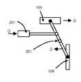
本発明の第1の実施例にかかる走査型画像表示装置の光学系を図1を用いて説明する。図1は、被走査面106に透過型拡散板を配置した走査型画像観察装置の光学系の構成を示す。このような走査型画像観察装置は映像信号に基づいて所定の画像を表示する頭部装着型映像表示装置や、デジタルカメラ等の電子式ビューファンダーシステムに好適なものである。 The optical system of the scanning image display apparatus according to the first embodiment of the present invention will be described with reference to FIG. FIG. 1 shows a configuration of an optical system of a scanning image observation apparatus in which a transmission type diffusion plate is arranged on a surface to be scanned 106. Such a scanning image observation apparatus is suitable for a head-mounted image display apparatus that displays a predetermined image based on a video signal and an electronic view funder system such as a digital camera.
図1中、光源101は、表示すべき画像の入力信号に基づき、不図示の駆動制御回路により変調される。光源101より、放射した光束は、集光光学系102を通過後、折り返し光学系103を介して走査手段104に向かう。走査手段104の内部には、半導体プロセスで製造された反射面を有する走査デバイスがあり、その反射面を動作させることで走査デバイス内の偏向点105に入射した光は走査デバイスにより偏向される。走査手段104により偏向された光束は、被走査面106を二次元的に走査し、走査手段104の走査特性と、光源101の変調を所定の制御手段によって同期をとることで、被走査面106上に形成される光源像を走査して映像信号にもとづいた画像が表示される。光学系107は、被走査面106を観察者が観察するための接眼光学系である。被走査面106には、拡散板が配置してあり、光源からの入射光束を拡散することで走査された光束によって形成される画像を観察者に提示するスクリーンとして機能し、観察者は被走査面106に再現された画像を実像又は虚像として認識する。 In FIG. 1, a
走査手段104により偏向された光束は、被走査面106上に光源像を形成するが、被走査面106は、透過型で拡散作用を有する面として構成されているため、入射した光束は、被走査面106で拡散され、光学系107を通って射出する。観察者は、射出瞳108近傍に、観察者の瞳をおくことで、被走査面106上に形成される画像を観察することができる。この時、集光光学系102に関して光源101と共役の位置に正確に被走査面106を配置することで、被走査面106に入射する光束の径は最小になり、解像度の高い像を観察者に提示可能となる。 The light beam deflected by the
しかしながら、観察者の中には近視や遠視の人もいるために視度調整が要求される。視度調整は可動の補助的な光学系を設けることでも可能であるが、同時に装置が大型化してしまう問題がある。他の方法として、被走査面106を接眼光学系107に対して移動させる手法があるが、図1に示す構成を持つ走査型表示装置の場合では、被走査面106と光源101間の集光光学系102に関する共役関係(結像関係)が崩れるために、被走査面106上での光束の径が大きくなり、再現される像がボケてしまう。 However, diopter adjustment is required because some observers are myopic and hyperopic. Diopter adjustment can be performed by providing a movable auxiliary optical system, but there is a problem that the apparatus becomes large at the same time. As another method, there is a method of moving the
この問題を解決するために、図1に示すように、光源101と集光光学系102を含む光源ユニット109をAで示す方向に移動させ、同時に走査面106上での結像関係を保つために被走査面106の位置を、接眼光学系107をBの方向に移動することが有効である。当該Bの方向は、接眼光学系107と被走査面106間の光路長を変更する方向に平行な方向であって、例えば接眼光学系107の光軸方向と平行な方向である。当該Bの方向への移動によって、被走査面106で拡散された光束の観察者の瞳位置までの光路長を短くすることができる。また、それぞれを逆の方向に移動させることによって被走査面106で拡散された光束の観察者の瞳位置までの光路長を長くすることができる。このように視度調節のために被走査面106を移動した際に、その移動量に応じて結像関係を維持しながら光源ユニット109を移動することで、再現される像を良好に保ったまま観察者の視度を調整することが可能となる。 In order to solve this problem, as shown in FIG. 1, the
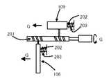
図2は、光源ユニット109と被走査面106を対応して移動させるための機構について示す図である。ここで、図1に示すような配置で光源ユニット109と被走査面106を配置すると、それぞれの部品は逆方向に移動するために、図2に示すように調整シャフト201に逆溝を作製しておき、光源ユニット109と被走査面106のそれぞれに調整シャフト201の溝と勘合する部位を作成しておく。これによって調整シャフト201を回すことによって、調整シャフト201の溝に沿って光源ユニット109と被走査面106は連動して移動するように構成することが可能である。 FIG. 2 is a diagram showing a mechanism for moving the
またそれぞれの部品を移動する方向を保つためにガイドの役割を果たし、ガタがなくスムーズに摺動することのできるシャフト202を通しておく。調整シャフト201をCの方向に回すことによって光源ユニット109と被走査面106をそれぞれC方向の移動を同時に行うことが可能となる。また調整シャフト201を逆向きに回すことによって両部材は前述した方向とは逆方向に移動する。光源ユニット109と被走査面106のそれぞれの移動量は調整シャフト201に作製した溝のピッチを変えることによって調整することが可能である。調整シャフト201の回転方向とそれぞれの部材の移動方向は逆でも構わない。ガタをなくすため、図2に示すように光源ユニット109と被走査面106を調整シャフト201の片端に押し当てるようにバネ203で圧力をかけておくことで精度良く移動させることが可能となる。他の方法としては、シャフト202とそれと勘合する穴の部位を摩擦抵抗の大きなゴムや樹脂で作製しておき、適度な力を加えないと摺動しない構成にしても良い。 Further, the
また図3に光源ユニット109と被走査面106の移動方法の別形態を示す。ある支点301を中心に回転運動をするヒンジの両端に光源ユニット109と被走査面106を接続しておき、片端点を押し下げるように支点301からずれた位置を押すことによって、他端が上がるようにしておく。調整シャフト201をDの方向に動かすことによって、光源ユニット109と被走査面106がDで示す方向に動く。また調整シャフト201逆向きに移動させることによって光源ユニット109、被走査面106も逆方向に動く。またこの調整シャフト201の代りに任意の位置で固定することのできる軸とリングの勘合した部材を用いても良い。また、調整は手動でも電動でも良い。これらの調整には組立時の光源ユニット109と被走査面106の位置調整部品を兼用することができるために部品点数を減らすことが可能となり、システムの小型化にもなる。 FIG. 3 shows another mode of moving the
他の方法として、光源ユニット109を移動させる代りに、集光光学系102のみを移動させ、視度調節のために移動した被走査面106と光源101が共役の位置となるように集光光学系102を移動させることによって結像関係を崩さず、被走査面106で拡散された光束の観察者の瞳位置までの距離を変え良好な視度調節を行うことができる。 As another method, instead of moving the
また他の手法として、光源101から走査手段104までを含む走査ユニット110を、前述した光源ユニット109の代りに被走査面106と連動して移動させることによっても同様の効果が得られる。 As another method, the same effect can be obtained by moving the
これらの手法を用いることによって、視度調整用の可動の光学系を特別に設けることなく、視度調整を行うことが可能となる。 By using these methods, it is possible to perform diopter adjustment without specially providing a movable optical system for diopter adjustment.
本発明の第2の実施例にかかる走査型画像表示装置の光学系を図4を用いて説明する。図4は、被走査面106に透過型拡散板を配置した走査型画像観察装置の光学系で実施例1と部品配置が異なった構成を示す。尚、説明の簡単のために、光学系の構成において実施例1と共通するものには同じ符号を付し、主に実施例1とは異なる部分について以下に説明する。 The optical system of the scanning image display apparatus according to the second embodiment of the present invention will be described with reference to FIG. FIG. 4 shows an optical system of a scanning type image observation apparatus in which a transmission type diffusion plate is arranged on the surface to be scanned 106, in which the component arrangement differs from that in the first embodiment. For the sake of simplicity, the same reference numerals are given to the same components in the configuration of the optical system as those in the first embodiment, and portions different from those in the first embodiment will be mainly described below.
図5は光源ユニット109と被走査面106を対応して移動させるための機構について示す図である。図4に示すような配置で光源ユニット109と被走査面106を配置すると、被走査面106の移動による視度調節の際には、それぞれの部品は同じ方向に移動する。このために、図5に示すように調整シャフト201に溝を作製しておき、それぞれの部位に光源ユニット109と被走査面106を連動して移動するように構成しておく。調整シャフト201をGの方向に回すことによって光源ユニット109と被走査面106をG方向に同時に移動させることが可能となる。また調整シャフト201を逆向きに回すことによって両部材は前述した方向とは逆方向に移動する。調整シャフト201の回転方向とそれぞれの部材の移動方向は逆でも構わない。 FIG. 5 is a diagram showing a mechanism for moving the
また図6に光源ユニット109と被走査面106の別の移動方法を示す。ある支点301を中心に回転運動をするヒンジに光源ユニット109と被走査面106を接続する。図6に示すように支点301からずれた位置を動かすことによって、光源ユニット109、被走査面106が同方向に移動するように構成しておく。この調整シャフト201をHの方向に移動させることによって、光源ユニット109と被走査面106がHで示す方向に動く。また調整シャフト201逆向きに移動させることによって光源ユニット109、被走査面106も逆方向に動く。またこの調整シャフト201の変わりに任意の位置で固定することのできる軸とリングの勘合した部材を用いても良い。また、調整は手動でも自動でも良い。これらの調整には組立時の光源ユニット109と被走査面106の位置調整部品を兼用することができるために部品点数を減らすことが可能となり、システムの小型化にもなる。 FIG. 6 shows another method for moving the
他の方法として、光源ユニット109を移動させる代りに、集光光学系102のみを移動させ、視度調節のために移動した被走査面106と光源101が共役の位置となるように集光光学系102を移動させることによって結像関係を崩さず、被走査面106で拡散された光束の観察者の瞳位置までの距離を変え良好な視度調節を行うことができる。 As another method, instead of moving the
また他の手法として、光源101から走査手段104までを含む走査ユニット110を、前述した光源ユニット109の代りに被走査面106と連動して移動させることによっても同様の効果が得られる。 As another method, the same effect can be obtained by moving the
これらの手法を用いることによって、視度調整用の可動の光学系を特別に設けることなく、視度調整を行うことが可能となる。 By using these methods, it is possible to perform diopter adjustment without specially providing a movable optical system for diopter adjustment.
本発明の第3の実施例にかかる走査型画像観察装置の光学系を図7を用いて説明する。図7は、被走査面106に反射型拡散板を配置した走査型画像観察装置の光学系の構成を示す。被走査面106を反射型とし、当該被走査面106に入射する光束と反射する光束を分離するためのハーフミラー701を備えている点で実施例1の光学系と異なる。 The optical system of the scanning image observation apparatus according to the third embodiment of the present invention will be described with reference to FIG. FIG. 7 shows a configuration of an optical system of a scanning image observation apparatus in which a reflection type diffusing plate is arranged on the surface to be scanned 106. It differs from the optical system of the first embodiment in that the scanned
図7中、光源101は、表示すべき画像の入力信号に基づいて、不図示の駆動制御回路により変調される。光源101より、放射した光束は、集光光学系102を通過後、折り返し光学系103を介して走査手段104に向かう。走査手段104の内部には、半導体プロセスで製造された走査デバイスがあり、その走査デバイス内の偏向点105に入射した光は走査デバイスにより偏向される。走査手段104により偏向された光束は、ハーフミラー701を透過して被走査面106を二次元的に走査する。この時、走査手段104の走査特性と、光源101の変調の同期をとることで、被走査面106上に光源像を形成して映像信号にもとづいた画像が表示される。光学系107は、被走査面106を観察者が観察するための接眼光学系である。被走査面106には拡散板が配置してあり、光源101からの入射光束を拡散して走査する。 In FIG. 7, the
走査手段104により偏向された光束は、被走査面106上に光源像を形成するが、被走査面106は、反射型で拡散作用を有する面として構成されているため、入射した光束は、被走査面106で反射拡散され、ハーフミラー701で反射偏向された光束が光学系107を通って射出する。観察者は、射出瞳108近傍に、観察者の目をおくことで、被走査面106上に形成される画像を観察することができる。この時、集光光学系102に関して光源101と共役の位置に正確に被走査面106を配置することで、被走査面106に入射する光束の径は最小になり、解像度の高い像を観察者に提示可能となる。 The light beam deflected by the
図7に示す光学系において良好な視度調節を行うためには、光源101と集光光学系102を含む光源ユニット109をIで示す方向に移動させ、走査面106上での結像関係を保つためには被走査面106の位置をJの方向に方向に移動することが有効である。これによって、被走査面106で拡散された光束の観察者の瞳位置までの光路長を短くすることになるためである。また、それぞれを逆方向に移動させることによって被走査面106で拡散された光束の観察者の瞳位置までの光路長を長くすることができる。このように視度調節のために被走査面106を移動した際に、その移動量に応じて光源ユニット109を移動することで、再現される像を良好に保ったまま観察者の視度を調整することが可能となる。 In order to perform satisfactory diopter adjustment in the optical system shown in FIG. 7, the
ここで、図7に示すような配置で光源ユニット109と被走査面106を配置すると、それぞれの部品は逆方向に移動するために、実施例1に関して図2で示したような手法で光源ユニット109と被走査面106を移動させることによって視度調整を行うことが可能となる。これらの調整には組立時の光源ユニット109と被走査面106の位置調整部品を兼用することができるために部品点数を減らすことが可能となり、システムの小型化にもなる。 Here, when the
他の方法として、光源ユニット109を移動させる代りに、集光光学系102のみを移動させ、視度調節のために移動した被走査面106と光源101が共役の位置となるように集光光学系102を移動させることによって結像関係を崩さず、被走査面106で拡散された光束の観察者の瞳位置までの距離を変え良好な視度調節を行うことができる。 As another method, instead of moving the
また他の手法として、光源101から走査手段104までを含む走査ユニット110を前述した光源ユニット109の代りに被走査面106を連動して移動させることによっても同様の効果が得られる。 As another method, the same effect can be obtained by moving the
これらの手法を用いることによって、今までは別に設けていた視度調整用の可動の光学系を設けることなく、視度調整を行うことが可能となる。 By using these methods, it is possible to perform diopter adjustment without providing a movable optical system for diopter adjustment that has been provided separately until now.
本発明の第4の実施例にかかる走査型画像観察装置の光学系を図8を用いて説明する。図8は、被走査面106に反射型拡散板を配置した走査型画像観察装置の光学系の構成を示す。実施例3と部品配置が異なった構成を示す。尚、説明の簡単のために、光学系の構成において実施例3と共通するものには同じ符号を付し、実施例3とは異なる部分についてのみ以下に説明する。 The optical system of the scanning image observation apparatus according to the fourth embodiment of the present invention will be described with reference to FIG. FIG. 8 shows a configuration of an optical system of a scanning image observation apparatus in which a reflection type diffusing plate is arranged on the surface to be scanned 106. The structure from which Example 3 differs in component arrangement is shown. For the sake of simplicity of explanation, the same reference numerals are given to the same components in the configuration of the optical system as those in the third embodiment, and only portions different from the third embodiment will be described below.
ここで、図8に示すような配置で光源ユニット109と被走査面106を配置すると、それぞれの部品は同方向に移動するために、実施例2について図5で示したような手法で光源ユニット109と被走査面106を移動させることによって視度調整を行うことが可能となる。これらの調整には組立時の光源ユニット109と被走査面106の位置調整部品を兼用することができるために部品点数を減らすことが可能となり、システムの小型化にもなる。 Here, when the
これらの手法を用いることによって、視度調整用の可動の光学系を特別に設けることなく、視度調整を行うことが可能となる。 By using these methods, it is possible to perform diopter adjustment without specially providing a movable optical system for diopter adjustment.
各実施例に示した構成においては、光源101と被走査面106の間に集光光学系102を配置しているだけなので、光源ユニット109と被走査面106の移動量は等しいが、走査手段104と被走査面106の間に光学系を配置している場合等は、被走査面106の移動量はその光学系の倍率を考慮した移動量となるために光源ユニット109の移動量とは異なる。 In the configuration shown in each embodiment, since the condensing
また本実施例においては、光源101としては、単色光のものを使用してもよいが、赤、緑、青の光を独立に発光する光源を色合成手段により組みあわせた構成とし、映像信号に基づいて独立に各色の光源の発光特性を制御することで観察者がカラー画像を観察することが可能となることは言うまでもない。 In the present embodiment, the
また本実施例においては、走査手段104として、図9に図示した構成の走査手段が考えられる。図9は走査手段104内の、半導体プロセスで製造された走査デバイス901である。走査面902は、トーションバー903をねじれ軸として、軸904を略中心として、共振往復揺動運動する。またさらに、トーションバー905を軸906として往復揺動運動する。2つの揺動運動を起こさせるアクチュエータとして、不図示の例えば、電磁力、静電気力などを使用したものが考えられる。このように走査デバイス901は2次元に走査できるデバイスであり、被走査面106上をラスタ走査できるようになっている。 In this embodiment, the
101 光源
102 集光光学系
103 折り返し光学系
104 走査手段
105 偏向点
106 被走査面
107 瞳結像光学系
108 射出瞳
109 光源ユニット
110 走査ユニット
201 調整シャフト
202 シャフト
203 バネ
301 支点
701 ハーフミラー
901 走査デバイス
902 走査面
903 トーションバー
904 軸
905 トーションバー
906 軸DESCRIPTION OF
Claims (5)
Translated fromJapanesePriority Applications (2)
| Application Number | Priority Date | Filing Date | Title |
|---|---|---|---|
| JP2003340789AJP4298455B2 (en) | 2003-09-30 | 2003-09-30 | Scanning image display device |
| US10/946,467US7609229B2 (en) | 2003-09-30 | 2004-09-21 | Image displaying apparatus |
Applications Claiming Priority (1)
| Application Number | Priority Date | Filing Date | Title |
|---|---|---|---|
| JP2003340789AJP4298455B2 (en) | 2003-09-30 | 2003-09-30 | Scanning image display device |
Publications (3)
| Publication Number | Publication Date |
|---|---|
| JP2005107179A JP2005107179A (en) | 2005-04-21 |
| JP2005107179A5 JP2005107179A5 (en) | 2006-11-16 |
| JP4298455B2true JP4298455B2 (en) | 2009-07-22 |
Family
ID=34373418
Family Applications (1)
| Application Number | Title | Priority Date | Filing Date |
|---|---|---|---|
| JP2003340789AExpired - Fee RelatedJP4298455B2 (en) | 2003-09-30 | 2003-09-30 | Scanning image display device |
Country Status (2)
| Country | Link |
|---|---|
| US (1) | US7609229B2 (en) |
| JP (1) | JP4298455B2 (en) |
Families Citing this family (22)
| Publication number | Priority date | Publication date | Assignee | Title |
|---|---|---|---|---|
| JP4504728B2 (en)* | 2003-11-21 | 2010-07-14 | 健爾 西 | Image display device and simulation device |
| JP4933056B2 (en)* | 2005-05-11 | 2012-05-16 | キヤノン株式会社 | Image display device and imaging device using the same |
| JP4829765B2 (en)* | 2006-12-08 | 2011-12-07 | キヤノン株式会社 | Image display device and image display system |
| JP5229327B2 (en)* | 2008-09-26 | 2013-07-03 | コニカミノルタアドバンストレイヤー株式会社 | Video display device, head-mounted display, and head-up display |
| WO2010062479A1 (en)* | 2008-11-02 | 2010-06-03 | David Chaum | System and apparatus for eyeglass appliance platform |
| KR101660411B1 (en)* | 2010-07-22 | 2016-09-28 | 삼성전자주식회사 | Super multi-view 3D display apparatus |
| US8681426B2 (en) | 2011-11-04 | 2014-03-25 | Honeywell International Inc. | Steerable near-to-eye display and steerable near-to-eye display system |
| WO2014155288A2 (en)* | 2013-03-25 | 2014-10-02 | Ecole Polytechnique Federale De Lausanne (Epfl) | Method and apparatus for head worn display with multiple exit pupils |
| WO2015025196A1 (en)* | 2013-08-23 | 2015-02-26 | Koc Universitesi | Method for autostereoscopic projection displays |
| JP6333007B2 (en)* | 2014-03-18 | 2018-05-30 | パイオニア株式会社 | Virtual image display device |
| CN103995355B (en)* | 2014-05-23 | 2016-06-01 | 北京理工大学 | The optical system of a kind of adjustable diopter for Helmet Mounted Display |
| CN106461939B (en)* | 2015-05-29 | 2019-03-15 | 深圳市柔宇科技有限公司 | From the method and head-mounted display apparatus of adaptation vision-control |
| US10732414B2 (en)* | 2016-08-17 | 2020-08-04 | Microsoft Technology Licensing, Llc | Scanning in optical systems |
| JP6731821B2 (en)* | 2016-09-28 | 2020-07-29 | 京セラ株式会社 | Display device and display system |
| US10553139B2 (en) | 2016-11-10 | 2020-02-04 | Microsoft Technology Licensing, Llc | Enhanced imaging system for linear micro-displays |
| WO2018093562A1 (en)* | 2016-11-16 | 2018-05-24 | Google Llc | Freeform projected display |
| WO2018112913A1 (en)* | 2016-12-23 | 2018-06-28 | 深圳市柔宇科技有限公司 | Head-mounted display device and dioptre display method therefor |
| US20180275408A1 (en)* | 2017-03-13 | 2018-09-27 | Htc Corporation | Head-mounted display apparatus |
| CN107300771B (en)* | 2017-06-21 | 2019-11-29 | 常州快来信息科技有限公司 | Wear the vision optimization method of 3D display equipment |
| JP2019074582A (en) | 2017-10-13 | 2019-05-16 | ソニー株式会社 | Information processing apparatus, information processing method, and program |
| JP2018124575A (en)* | 2018-04-24 | 2018-08-09 | パイオニア株式会社 | Virtual image display device |
| JP7685724B2 (en)* | 2022-03-01 | 2025-05-30 | 福井県 | Video Projection Equipment |
Family Cites Families (12)
| Publication number | Priority date | Publication date | Assignee | Title |
|---|---|---|---|---|
| US5467104A (en)* | 1992-10-22 | 1995-11-14 | Board Of Regents Of The University Of Washington | Virtual retinal display |
| US5757544A (en)* | 1993-03-09 | 1998-05-26 | Olympus Optical Co., Ltd. | Image display apparatus |
| JP2722314B2 (en) | 1993-12-20 | 1998-03-04 | 日本信号株式会社 | Planar type galvanometer mirror and method of manufacturing the same |
| TW307863B (en)* | 1994-03-15 | 1997-06-11 | Ibm | |
| JPH08334723A (en) | 1995-06-06 | 1996-12-17 | Olympus Optical Co Ltd | Optical deflection element |
| US5701132A (en)* | 1996-03-29 | 1997-12-23 | University Of Washington | Virtual retinal display with expanded exit pupil |
| US6043799A (en)* | 1998-02-20 | 2000-03-28 | University Of Washington | Virtual retinal display with scanner array for generating multiple exit pupils |
| US6396461B1 (en)* | 1998-08-05 | 2002-05-28 | Microvision, Inc. | Personal display with vision tracking |
| JP2000258844A (en) | 1999-03-09 | 2000-09-22 | Sony Corp | Video display device |
| JP2001027738A (en) | 1999-07-14 | 2001-01-30 | Minolta Co Ltd | Video display device |
| US7001019B2 (en)* | 2000-10-26 | 2006-02-21 | Canon Kabushiki Kaisha | Image observation apparatus and system |
| JP4058251B2 (en)* | 2001-09-07 | 2008-03-05 | キヤノン株式会社 | Scanning image display optical system, scanning image display device, and image display system |
- 2003
- 2003-09-30JPJP2003340789Apatent/JP4298455B2/ennot_activeExpired - Fee Related
- 2004
- 2004-09-21USUS10/946,467patent/US7609229B2/ennot_activeExpired - Fee Related
Also Published As
| Publication number | Publication date |
|---|---|
| US20050068255A1 (en) | 2005-03-31 |
| JP2005107179A (en) | 2005-04-21 |
| US7609229B2 (en) | 2009-10-27 |
Similar Documents
| Publication | Publication Date | Title |
|---|---|---|
| JP4298455B2 (en) | Scanning image display device | |
| EP2187259B1 (en) | Projector | |
| JP5223452B2 (en) | Projector, projection image forming method, and vehicle head-up display device | |
| JP4731938B2 (en) | Image display device / projection optical system | |
| KR101193524B1 (en) | Optical scan unit, image projector including the same, vehicle head-up display device, and mobile phone | |
| JP3489841B2 (en) | Display device incorporating a one-dimensional high-speed grating light valve array | |
| Urey et al. | Scanner design and resolution trade-offs for miniature scanning displays | |
| JP4574394B2 (en) | Scanning image display device | |
| US10216079B2 (en) | Scanning projector screen, and scanning projector system | |
| JP2010145769A (en) | Image display | |
| EP3982189B1 (en) | Image display device and display device | |
| JP2006178033A (en) | Scanning display optical system | |
| JP4095428B2 (en) | Optical scanning optical system, image projection apparatus, and image display system | |
| US7361878B2 (en) | Image display apparatus and image pickup apparatus with two dimensional scanning | |
| JP4689266B2 (en) | Image display device | |
| WO2005057269A1 (en) | Display unit and scanning method therefor | |
| JP4641378B2 (en) | Optical scanning device and image display device having the same | |
| US7508553B2 (en) | Image displaying apparatus and image pickup apparatus having the same | |
| JP2004347687A (en) | Scanning image display device and optical system for scanning image display device | |
| CN114488539A (en) | A scanning display module and a near-eye display device | |
| JP2007121581A (en) | Scanning image display device, imaging device, and image display system | |
| JP2021152565A (en) | Display unit and optical element | |
| JP4817637B2 (en) | Image display apparatus and imaging apparatus having the same | |
| KR100880282B1 (en) | Image display and projection optical system | |
| WO2009136588A1 (en) | Projection image display device |
Legal Events
| Date | Code | Title | Description |
|---|---|---|---|
| A521 | Request for written amendment filed | Free format text:JAPANESE INTERMEDIATE CODE: A523 Effective date:20061002 | |
| A621 | Written request for application examination | Free format text:JAPANESE INTERMEDIATE CODE: A621 Effective date:20061002 | |
| A977 | Report on retrieval | Free format text:JAPANESE INTERMEDIATE CODE: A971007 Effective date:20090108 | |
| A131 | Notification of reasons for refusal | Free format text:JAPANESE INTERMEDIATE CODE: A131 Effective date:20090120 | |
| A521 | Request for written amendment filed | Free format text:JAPANESE INTERMEDIATE CODE: A523 Effective date:20090323 | |
| TRDD | Decision of grant or rejection written | ||
| A01 | Written decision to grant a patent or to grant a registration (utility model) | Free format text:JAPANESE INTERMEDIATE CODE: A01 Effective date:20090414 | |
| A01 | Written decision to grant a patent or to grant a registration (utility model) | Free format text:JAPANESE INTERMEDIATE CODE: A01 | |
| A61 | First payment of annual fees (during grant procedure) | Free format text:JAPANESE INTERMEDIATE CODE: A61 Effective date:20090415 | |
| R150 | Certificate of patent or registration of utility model | Free format text:JAPANESE INTERMEDIATE CODE: R150 | |
| FPAY | Renewal fee payment (event date is renewal date of database) | Free format text:PAYMENT UNTIL: 20120424 Year of fee payment:3 | |
| LAPS | Cancellation because of no payment of annual fees |