JP4292643B2 - Gas pressure detector - Google Patents
Gas pressure detectorDownload PDFInfo
- Publication number
- JP4292643B2 JP4292643B2JP25523899AJP25523899AJP4292643B2JP 4292643 B2JP4292643 B2JP 4292643B2JP 25523899 AJP25523899 AJP 25523899AJP 25523899 AJP25523899 AJP 25523899AJP 4292643 B2JP4292643 B2JP 4292643B2
- Authority
- JP
- Japan
- Prior art keywords
- pressure
- sensor element
- pressure sensor
- gas
- circuit
- Prior art date
- Legal status (The legal status is an assumption and is not a legal conclusion. Google has not performed a legal analysis and makes no representation as to the accuracy of the status listed.)
- Expired - Fee Related
Links
Images


Landscapes
- Measuring Volume Flow (AREA)
- Measuring Fluid Pressure (AREA)
Description
Translated fromJapanese【0001】
【発明の属する技術分野】
本発明は、LPガス、都市ガス等の被測定気体のガス圧力検知装置に関する。
【0002】
【従来の技術】
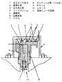
従来のこの種の半導体式圧力検知装置を図5に基づいて説明する。
【0003】
図5において、30は圧力センサ装着部、31は外枠、32は圧力導入口、33は半導体圧力センサ素子で、シリコン基盤上にエッチングにより設けられた厚み10μm程度のダイヤフラム膜が最下面にあり、この膜上に受圧で生じる機械的歪により電気抵抗値が変化する半導体抵抗が形成されている。34は台座で、通常半導体圧力センサ素子33の熱膨張係数に近い金属、ガラス等で構成され、前記機械的歪を吸収する柔軟性のある緩衝材として、また半導体圧力センサ素子33を保持するように使用されている。35はリードフレームで、半導体圧力センサ素子33と回路基板38を保持してセンサケース37に固定している。
【0004】
36は接合部で、接着剤または、共晶接合等200℃程度の高温によって台座34とセンサケース37の接合が行われている。センサケース37は上部に大気と通じる差圧孔42を備えている。38は増幅回路等の電気回路が形成された回路基板、39は外枠31とセンサース37を接合する接着剤、40はプラスチック樹脂によりセンサケース37等をモールドした樹脂モールド、また半導体圧力センサ素子33の外側には、大気中のゴミや水分が直接接触しないように、圧力伝達にエラーを生じない程度に十分に軟質のゲル41がコーティングされた構成となっている。
【0005】
【発明が解決しようとする課題】
このガス圧力検知装置はガスメータ等に装着され、ガス圧力の監視等の機能を果たしているが、このガスメータが万一火災等に遭遇した場合、周囲温度の上昇により材料が高温劣化して、ガス漏れの可能性があるという課題があった。
【0006】
本発明は、火災等による周囲温度の上昇時に圧力検知通路を閉止することにより、ガス漏れを防止する高信頼性のガス圧力検知装置を実現することを目的とする。
【0007】
【課題を解決するための手段】
この課題を解決するために本発明は、火災等による周囲温度の上昇時に耐熱材料で構成した圧力検知通路を閉止し、ガス漏れを防止するように構成したものである。これにより、火災等の周囲温度上昇時でもガス漏れ発生のない高信頼性の圧力検知装置が得られる。
【0008】
【発明の実施の形態】
本発明の請求項1に記載の発明は、受圧膜の受圧歪みを電気信号として出力する圧力センサ素子と、前記圧力センサ素子の下面に接合された応力緩衝台座と前記緩衝台座と接着剤を介して保持し、周囲と気密に囲まれた圧力検知通路を構成し、内部に通路の閉止を目的とした温度ヒューズ回路を内蔵する圧力導入管と、前記圧力センサ素子からの電気信号をワイヤーを介し回路基板に伝送するリードフレームと、前記圧力センサ素子からの電気信号を温度特性データにより調整及び増幅し装置外へ出力する回路基板と前記圧力導入管とリードフレームを樹脂で一体成形され前記回路基板を収納する下ケースと装着部に固定する固定部を設けて前記下ケースを収容する上ケースとを備え、前記圧力導入管通路内部に半田リングと網状の隔壁を備えたガス圧力検知装置としたものである。
【0009】
そして、圧力導入管内部に通路の閉止を目的とした温度ヒューズ回路を内蔵することにより、火災等で周囲温度が上昇した場合のガス漏れ防止が実現出来る作用を有する。また、火災等により周囲温度が上昇した場合、半田リングが溶融し網状の隔壁を閉止して、ガス漏れを防止する作用を有する。
【0012】
【実施例】
以下、本発明のガス圧力検知装置の実施例について図1から図4を用いて説明する。
【0013】
(実施例1)
図1は実施例1のガス圧力検知装置の断面図、図1において、半導体の圧力センサ素子1は、シリコン基板上にエッチングにより設けられた厚み10μm程度のダイヤフラム膜を構成しており、このダイヤフラム膜上に圧力印加に伴う機械的歪により抵抗値が変化する半導体抵抗が形成されている。
【0014】
この圧力センサ素子1の下面に接合された緩衝台座2を接着剤3を介してし、内部に火災等の高温異常時の通路の閉止を目的とした温度ヒューズ回路11を内蔵する圧力導入管4で保持し周囲と気密状態で囲まれた圧力検知回路を構成している。
【0015】
電気的には、圧力センサ素子1〜ワイヤ7〜リードフレーム4〜回路基板6で接続されており、回路基板6は図示はしない増幅回路等の電気回路が形成されている。
【0016】
下ケース9は、圧力導入管3とリードフレーム4を一体成形し回路基板6を収納し、装着部12への固定部を設けてなる上ケース10に収納された構成となっている。
【0017】
上記構成に基づき以下、作用について説明する。
【0018】
下ケース9の下部にある圧力導入管3から印加される被測定気体(LPガス、都市ガス)の圧力と大気圧との差圧により、圧力センサ素子1が機械的歪を生じ、その機械的歪は、印加圧力と大気圧の差圧に比例する。
【0019】
圧力センサ素子1が歪を発生すると、圧力センサ素子1上に形成された半導体抵抗の抵抗値が歪の大きさに比例して変化する。この抵抗値変化を検出し、回路基板6上に設けられた増幅回路で増幅した電気信号を出力することにより、印加圧力と大気圧の差圧を測定している。
【0020】
この圧力検知装置が火災等のため周囲温度が上昇した場合、圧力検査装置の各部品材料は高温劣化を発生し、最終的にはガス通路部よりのガス漏れにつながる場合も考えられる。
【0021】
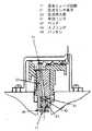
本実施例では各部品材料の高温劣化に至る前に、図2の温度ヒューズ回路11が動作する。周囲の温度上昇によって、半田リング41が溶融しロッド42がスプリング43の押し力に応じて半田リング41方向に押し上げられパッキン44が圧力導入管23に密着して通路を閉止することとなる。
【0022】
以上のように本実施例によれば、火災等による周囲温度の上昇時に各部品材料が高温劣化する以前に温度ヒューズ回路を動作させ、圧力検知通路を閉止することにより、ガス漏れを防止する高信頼性のガス圧力検知装置を実現することができる。
【0023】
(実施例2)
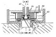
図3は、実施例2の圧力導入管4の断面を示す。図3において、圧力導入管4の下部に高温で溶融する半田リング13と網状隔壁14が設けてある。
【0024】
上記構成に基づき以下、作用について説明する。
【0025】
周囲の温度上昇によって、半田リング41が溶融し下部に設けられた網状隔壁14の表面に滴下する。滴下した半田は表面張力により網状隔壁表面を閉塞し圧力検知通路を閉止することとなる。
【0026】
以上のように本実施例によれば、火災等による周囲温度の上昇時に各部品材料が高温劣化する以前に網状隔壁14を半田で閉塞することにより、圧力検知通路を閉止することにより、万が一のガス漏れを防止することができる。
【0027】
(実施例3)
図4は、実施例3の形状記憶弁15を示し、図4において、圧力導入管4の下部に形状記憶合金で製作された形状記憶弁15が設けてあり、圧力導入管内部先端にはシールパッキン16が設けてある。
【0028】
上記構成に基づき以下、作用について説明する。
【0029】
形状記憶弁は温度上昇により変形し常温以下で元の形状に戻る動作ヒステリシスの大きな変形形態を行う特性である。周囲の温度上昇によって、形状記憶弁15がシールパッキン方向に変形することにより、形状記憶弁15とシールパッキン16が密着して圧力検知通路を閉止することとなる。
【0030】
以上のように本実施例によれば、火災等による周囲温度の上昇時に各部品材料が高温劣化する以前に形状記憶弁15が変形してシールパッキン16に密着することにより、圧力検知通路が閉止されガス漏れを防止するという有利な効果が得られる。
【0031】
【発明の効果】
以上のように本発明は、万が一の火災等の異常時にもガス漏れにむすびつかない高信頼性のガス圧力検知装置を実現できる。
【図面の簡単な説明】
【図1】本発明の実施例1におけるガス圧力検知装置の断面図
【図2】同装置の温度ヒューズ回路を示す断面図
【図3】本発明の実施例2におけるガス圧力検知装置の圧力導入管を示す断面図
【図4】本発明の実施例3におけるガス圧力検知装置の形状記憶弁を示す断面図
【図5】従来の圧力検知装置の断面図
【符号の説明】
1、21 圧力センサ素子
2 緩衝台座
3、23 圧力導入管
4 リードフレーム
5 接着剤
6 回路基板
7 ワイヤー
8 ポッテング剤(ゲル状)
9 下ケース
10 上ケース
11 温度ヒューズ回路
12 装着部
13 半田リング
14 網状隔壁
15 形状記憶弁[0001]
BACKGROUND OF THE INVENTION
The present invention relates to a gas pressure detection device for a gas to be measured such as LP gas and city gas.
[0002]
[Prior art]
A conventional semiconductor pressure detector of this type will be described with reference to FIG.
[0003]
In FIG. 5, 30 is a pressure sensor mounting portion, 31 is an outer frame, 32 is a pressure inlet, 33 is a semiconductor pressure sensor element, and a diaphragm film having a thickness of about 10 μm provided on the silicon substrate by etching is on the lowermost surface. On this film, a semiconductor resistor whose electric resistance value changes due to mechanical strain caused by pressure reception is formed. Reference numeral 34 denotes a pedestal, which is usually made of a metal, glass, or the like that has a thermal expansion coefficient close to that of the semiconductor
[0004]
[0005]
[Problems to be solved by the invention]
This gas pressure detector is attached to a gas meter and performs functions such as monitoring the gas pressure. However, if this gas meter encounters a fire, etc., the ambient temperature rises and the material deteriorates to a high temperature, causing gas leakage. There was a problem that there was a possibility of.
[0006]
An object of the present invention is to realize a highly reliable gas pressure detection device that prevents gas leakage by closing a pressure detection passage when an ambient temperature rises due to a fire or the like.
[0007]
[Means for Solving the Problems]
In order to solve this problem, the present invention is configured to close a pressure detection passage made of a heat-resistant material and prevent gas leakage when an ambient temperature rises due to a fire or the like. As a result, a highly reliable pressure detection device that does not cause gas leakage even when the ambient temperature rises such as a fire can be obtained.
[0008]
DETAILED DESCRIPTION OF THE INVENTION
According to a first aspect of the present invention, there is provided a pressure sensor element that outputs a pressure-receiving strain of a pressure-receiving film as an electric signal, a stress buffering base joined to a lower surface of the pressure sensor element, the buffering base, and an adhesive. And a pressure detection passage that is surrounded by air tightly and is surrounded by a pressure introduction pipe containing a temperature fuse circuit for the purpose of closing the passage, and an electric signal from the pressure sensor element via a wire. A lead frame that transmits to the circuit board, a circuit board that adjusts and amplifies the electrical signal from the pressure sensor element based on temperature characteristic data, and outputs the result to the outside of the apparatus, and the pressure introduction tube and the lead frame are integrally formed of resin provided fixing portion for fixing the mounting portion and the lower case for accommodating a upper case for housing the lower casea, Bei solder ring and mesh of the partition wall inside the pressure introduction pipe passage And it is obtained by the gas pressure detecting device.
[0009]
And by incorporating a temperature fuse circuit for the purpose of closing the passage inside the pressure introduction pipe, it has an effect of preventing gas leakage when the ambient temperature rises due to a fire or the like.In addition, when the ambient temperature rises due to a fire or the like, the solder ring melts and closes the net-like partition wall, thereby preventing gas leakage.
[0012]
【Example】
Embodiments of the gas pressure detection device of the present invention will be described below with reference to FIGS.
[0013]
Example 1
FIG. 1 is a cross-sectional view of a gas pressure detecting device according to a first embodiment. In FIG. 1, a semiconductor pressure sensor element 1 is configured by a diaphragm film having a thickness of about 10 μm provided by etching on a silicon substrate. A semiconductor resistor whose resistance value changes due to mechanical strain accompanying pressure application is formed on the film.
[0014]
A pressure introduction pipe 4 having a built-in
[0015]
Electrically, the pressure sensor element 1, the
[0016]
The lower case 9 has a configuration in which the
[0017]
The operation will be described below based on the above configuration.
[0018]
The pressure sensor element 1 is mechanically distorted by the differential pressure between the pressure of the gas to be measured (LP gas, city gas) applied from the
[0019]
When the pressure sensor element 1 generates strain, the resistance value of the semiconductor resistor formed on the pressure sensor element 1 changes in proportion to the magnitude of the strain. By detecting this change in resistance value and outputting an electric signal amplified by an amplifier circuit provided on the
[0020]
When the ambient temperature rises due to a fire or the like of this pressure detection device, each component material of the pressure inspection device may be deteriorated at a high temperature and may eventually lead to gas leakage from the gas passage portion.
[0021]
In this embodiment, the
[0022]
As described above, according to this embodiment, when the ambient temperature rises due to a fire or the like, the temperature fuse circuit is operated before each component material is deteriorated at a high temperature, and the pressure detection passage is closed to prevent gas leakage. A reliable gas pressure detection device can be realized.
[0023]
(Example 2)
FIG. 3 shows a cross section of the pressure introducing tube 4 of the second embodiment. In FIG. 3, a
[0024]
The operation will be described below based on the above configuration.
[0025]
As the ambient temperature rises, the
[0026]
As described above, according to this embodiment, by closing the pressure detection passage by closing the
[0027]
(Example 3)
FIG. 4 shows a
[0028]
The operation will be described below based on the above configuration.
[0029]
The shape memory valve has a characteristic of performing a deformation mode with a large operation hysteresis that is deformed by a temperature rise and returns to its original shape at a room temperature or lower. As the ambient temperature rises, the
[0030]
As described above, according to the present embodiment, when the ambient temperature rises due to a fire or the like, the
[0031]
【The invention's effect】
As described above, the present invention can realize a highly reliable gas pressure detection device that does not suffer from gas leakage even in the event of an abnormality such as a fire.
[Brief description of the drawings]
FIG. 1 is a cross-sectional view of a gas pressure detection device according to a first embodiment of the present invention. FIG. 2 is a cross-sectional view illustrating a temperature fuse circuit of the device. FIG. 3 is a pressure introduction of the gas pressure detection device according to a second embodiment of the present invention. FIG. 4 is a cross-sectional view showing a shape memory valve of a gas pressure detecting device in
1, 21
9
Claims (1)
Translated fromJapanesePriority Applications (1)
| Application Number | Priority Date | Filing Date | Title |
|---|---|---|---|
| JP25523899AJP4292643B2 (en) | 1999-09-09 | 1999-09-09 | Gas pressure detector |
Applications Claiming Priority (1)
| Application Number | Priority Date | Filing Date | Title |
|---|---|---|---|
| JP25523899AJP4292643B2 (en) | 1999-09-09 | 1999-09-09 | Gas pressure detector |
Publications (2)
| Publication Number | Publication Date |
|---|---|
| JP2001074580A JP2001074580A (en) | 2001-03-23 |
| JP4292643B2true JP4292643B2 (en) | 2009-07-08 |
Family
ID=17275964
Family Applications (1)
| Application Number | Title | Priority Date | Filing Date |
|---|---|---|---|
| JP25523899AExpired - Fee RelatedJP4292643B2 (en) | 1999-09-09 | 1999-09-09 | Gas pressure detector |
Country Status (1)
| Country | Link |
|---|---|
| JP (1) | JP4292643B2 (en) |
Families Citing this family (1)
| Publication number | Priority date | Publication date | Assignee | Title |
|---|---|---|---|---|
| JP7390544B2 (en)* | 2019-05-17 | 2023-12-04 | パナソニックIpマネジメント株式会社 | gas safety device |
- 1999
- 1999-09-09JPJP25523899Apatent/JP4292643B2/ennot_activeExpired - Fee Related
Also Published As
| Publication number | Publication date |
|---|---|
| JP2001074580A (en) | 2001-03-23 |
Similar Documents
| Publication | Publication Date | Title |
|---|---|---|
| US7162927B1 (en) | Design of a wet/wet amplified differential pressure sensor based on silicon piezoresistive technology | |
| JP4774678B2 (en) | Pressure sensor device | |
| JP3207123U (en) | Media isolation pressure sensor | |
| JP5739039B2 (en) | Pressure sensor | |
| JP2004513339A (en) | Pressure sensor module | |
| JP2001515588A (en) | Pressure sensor, constituent elements and manufacturing method | |
| JP6807486B2 (en) | Pressure sensor configuration and its manufacturing method | |
| JP4292643B2 (en) | Gas pressure detector | |
| US10908041B2 (en) | Device for measuring characteristics of a fluid | |
| JP5278448B2 (en) | Pressure sensor device | |
| JP2782572B2 (en) | Pressure sensor and method of manufacturing the same | |
| CN116425105A (en) | Sensor, sensor manufacturing method and smart wearable device | |
| JP3009971B2 (en) | Pressure sensor | |
| JP3081179B2 (en) | Pressure sensor and method of manufacturing the same | |
| JPH09178596A (en) | Pressure sensor | |
| JP3593397B2 (en) | Semiconductor pressure sensor | |
| JP3349489B2 (en) | Pressure sensor and method of manufacturing the same | |
| JPH08226861A (en) | Pressure sensor and its mounting structure | |
| JPH062189U (en) | Pressure sensor | |
| JP3149396B2 (en) | Manufacturing method of pressure sensor | |
| JP3189516B2 (en) | Gas pressure detector | |
| JPH095197A (en) | Semiconductor pressure sensor | |
| JPH0749275A (en) | Output circuit device for pressure sensor | |
| JPH10232177A (en) | Gas pressure detector | |
| JPH0843224A (en) | Pressure detector |
Legal Events
| Date | Code | Title | Description |
|---|---|---|---|
| A621 | Written request for application examination | Free format text:JAPANESE INTERMEDIATE CODE: A621 Effective date:20060830 | |
| RD01 | Notification of change of attorney | Free format text:JAPANESE INTERMEDIATE CODE: A7421 Effective date:20060913 | |
| A977 | Report on retrieval | Free format text:JAPANESE INTERMEDIATE CODE: A971007 Effective date:20081008 | |
| A131 | Notification of reasons for refusal | Free format text:JAPANESE INTERMEDIATE CODE: A131 Effective date:20081028 | |
| A521 | Written amendment | Free format text:JAPANESE INTERMEDIATE CODE: A523 Effective date:20081222 | |
| TRDD | Decision of grant or rejection written | ||
| A01 | Written decision to grant a patent or to grant a registration (utility model) | Free format text:JAPANESE INTERMEDIATE CODE: A01 Effective date:20090317 | |
| A01 | Written decision to grant a patent or to grant a registration (utility model) | Free format text:JAPANESE INTERMEDIATE CODE: A01 | |
| A61 | First payment of annual fees (during grant procedure) | Free format text:JAPANESE INTERMEDIATE CODE: A61 Effective date:20090330 | |
| FPAY | Renewal fee payment (event date is renewal date of database) | Free format text:PAYMENT UNTIL: 20120417 Year of fee payment:3 | |
| FPAY | Renewal fee payment (event date is renewal date of database) | Free format text:PAYMENT UNTIL: 20120417 Year of fee payment:3 | |
| LAPS | Cancellation because of no payment of annual fees |