JP4292360B2 - Device for forming a shaped axial hole through the spine - Google Patents
Device for forming a shaped axial hole through the spineDownload PDFInfo
- Publication number
- JP4292360B2 JP4292360B2JP2001559362AJP2001559362AJP4292360B2JP 4292360 B2JP4292360 B2JP 4292360B2JP 2001559362 AJP2001559362 AJP 2001559362AJP 2001559362 AJP2001559362 AJP 2001559362AJP 4292360 B2JP4292360 B2JP 4292360B2
- Authority
- JP
- Japan
- Prior art keywords
- drive shaft
- cutting
- distal end
- cutting head
- wire
- Prior art date
- Legal status (The legal status is an assumption and is not a legal conclusion. Google has not performed a legal analysis and makes no representation as to the accuracy of the status listed.)
- Expired - Fee Related
Links
- 238000005520cutting processMethods0.000claimsdescription176
- 238000005553drillingMethods0.000claimsdescription63
- 210000000988bone and boneAnatomy0.000claimsdescription45
- 239000000463materialSubstances0.000claimsdescription16
- 238000000227grindingMethods0.000claimsdescription15
- 238000003780insertionMethods0.000claimsdescription13
- 230000037431insertionEffects0.000claimsdescription13
- 239000012528membraneSubstances0.000claimsdescription7
- 230000000452restraining effectEffects0.000claims2
- 238000000034methodMethods0.000description45
- 239000007943implantSubstances0.000description35
- 238000013459approachMethods0.000description21
- 230000036961partial effectEffects0.000description13
- 230000008569processEffects0.000description12
- 238000001356surgical procedureMethods0.000description11
- 238000002684laminectomyMethods0.000description8
- 239000002184metalSubstances0.000description8
- 229910052751metalInorganic materials0.000description8
- 230000003416augmentationEffects0.000description7
- 230000004927fusionEffects0.000description7
- 208000002193PainDiseases0.000description6
- 210000000278spinal cordAnatomy0.000description6
- 210000000115thoracic cavityAnatomy0.000description6
- 238000003384imaging methodMethods0.000description5
- 210000003041ligamentAnatomy0.000description5
- 230000033001locomotionEffects0.000description5
- 208000008035Back PainDiseases0.000description4
- 230000008468bone growthEffects0.000description4
- 239000004568cementSubstances0.000description4
- 210000004705lumbosacral regionAnatomy0.000description4
- 230000007935neutral effectEffects0.000description4
- 238000002360preparation methodMethods0.000description4
- 206010041591Spinal osteoarthritisDiseases0.000description3
- 208000007103SpondylolisthesisDiseases0.000description3
- 230000002159abnormal effectEffects0.000description3
- 230000006378damageEffects0.000description3
- 238000011010flushing procedureMethods0.000description3
- 210000002414legAnatomy0.000description3
- 230000007246mechanismEffects0.000description3
- 210000005036nerveAnatomy0.000description3
- 230000035515penetrationEffects0.000description3
- 208000005801spondylosisDiseases0.000description3
- 230000008859changeEffects0.000description2
- 150000001875compoundsChemical class0.000description2
- 239000012530fluidSubstances0.000description2
- 238000002594fluoroscopyMethods0.000description2
- 230000003100immobilizing effectEffects0.000description2
- 238000002513implantationMethods0.000description2
- 210000003205muscleAnatomy0.000description2
- 239000007787solidSubstances0.000description2
- 125000006850spacer groupChemical group0.000description2
- 210000001519tissueAnatomy0.000description2
- 210000000689upper legAnatomy0.000description2
- 208000025940Back injuryDiseases0.000description1
- 208000010392Bone FracturesDiseases0.000description1
- AIGOAHIDIXDVAT-UHFFFAOYSA-NC1C2C3C2C3C1Chemical compoundC1C2C3C2C3C1AIGOAHIDIXDVAT-UHFFFAOYSA-N0.000description1
- 208000003618Intervertebral Disc DisplacementDiseases0.000description1
- 206010061246Intervertebral disc degenerationDiseases0.000description1
- 206010023509KyphosisDiseases0.000description1
- 208000007623LordosisDiseases0.000description1
- 208000008930Low Back PainDiseases0.000description1
- 208000006670Multiple fracturesDiseases0.000description1
- 208000006735PeriostitisDiseases0.000description1
- 244000208734Pisonia aculeataSpecies0.000description1
- 208000000875Spinal CurvaturesDiseases0.000description1
- 208000020307Spinal diseaseDiseases0.000description1
- 208000020339Spinal injuryDiseases0.000description1
- RTAQQCXQSZGOHL-UHFFFAOYSA-NTitaniumChemical compound[Ti]RTAQQCXQSZGOHL-UHFFFAOYSA-N0.000description1
- 230000009471actionEffects0.000description1
- 239000000853adhesiveSubstances0.000description1
- 230000001070adhesive effectEffects0.000description1
- 210000003484anatomyAnatomy0.000description1
- 238000004873anchoringMethods0.000description1
- 230000003466anti-cipated effectEffects0.000description1
- 210000000436anusAnatomy0.000description1
- 230000000712assemblyEffects0.000description1
- 238000000429assemblyMethods0.000description1
- 238000005452bendingMethods0.000description1
- 230000015572biosynthetic processEffects0.000description1
- 230000003139buffering effectEffects0.000description1
- 210000000845cartilageAnatomy0.000description1
- 230000006835compressionEffects0.000description1
- 238000007906compressionMethods0.000description1
- 238000002591computed tomographyMethods0.000description1
- 230000008878couplingEffects0.000description1
- 238000010168coupling processMethods0.000description1
- 238000005859coupling reactionMethods0.000description1
- 238000002788crimpingMethods0.000description1
- 238000013016dampingMethods0.000description1
- 230000003247decreasing effectEffects0.000description1
- 230000007547defectEffects0.000description1
- 230000007850degenerationEffects0.000description1
- 208000018180degenerative disc diseaseDiseases0.000description1
- 230000000994depressogenic effectEffects0.000description1
- 238000011161developmentMethods0.000description1
- 238000002059diagnostic imagingMethods0.000description1
- 230000010339dilationEffects0.000description1
- 208000037265diseases, disorders, signs and symptomsDiseases0.000description1
- 208000035475disorderDiseases0.000description1
- 210000002745epiphysisAnatomy0.000description1
- 210000000968fibrocartilageAnatomy0.000description1
- 210000001145finger jointAnatomy0.000description1
- ZZUFCTLCJUWOSV-UHFFFAOYSA-NfurosemideChemical compoundC1=C(Cl)C(S(=O)(=O)N)=CC(C(O)=O)=C1NCC1=CC=CO1ZZUFCTLCJUWOSV-UHFFFAOYSA-N0.000description1
- 230000035876healingEffects0.000description1
- 210000001624hipAnatomy0.000description1
- 210000004394hip jointAnatomy0.000description1
- 230000006698inductionEffects0.000description1
- 238000002347injectionMethods0.000description1
- 239000007924injectionSubstances0.000description1
- 238000012966insertion methodMethods0.000description1
- 208000021600intervertebral disc degenerative diseaseDiseases0.000description1
- 210000000281joint capsuleAnatomy0.000description1
- 210000000629knee jointAnatomy0.000description1
- 239000007788liquidSubstances0.000description1
- 210000004446longitudinal ligamentAnatomy0.000description1
- 230000014759maintenance of locationEffects0.000description1
- 238000004519manufacturing processMethods0.000description1
- 238000013507mappingMethods0.000description1
- 229910001092metal group alloyInorganic materials0.000description1
- 239000007769metal materialSubstances0.000description1
- 230000001537neural effectEffects0.000description1
- 230000007971neurological deficitEffects0.000description1
- 230000000399orthopedic effectEffects0.000description1
- 206010033675panniculitisDiseases0.000description1
- 210000004197pelvisAnatomy0.000description1
- 210000003460periosteumAnatomy0.000description1
- 230000002085persistent effectEffects0.000description1
- 238000003825pressingMethods0.000description1
- 230000001681protective effectEffects0.000description1
- 238000005086pumpingMethods0.000description1
- 238000011084recoveryMethods0.000description1
- 230000009467reductionEffects0.000description1
- 230000002829reductive effectEffects0.000description1
- 206010039722scoliosisDiseases0.000description1
- 238000004904shorteningMethods0.000description1
- 210000001032spinal nerveAnatomy0.000description1
- 238000003892spreadingMethods0.000description1
- 230000007480spreadingEffects0.000description1
- 230000000087stabilizing effectEffects0.000description1
- 210000004304subcutaneous tissueAnatomy0.000description1
- 239000000126substanceSubstances0.000description1
- 208000024891symptomDiseases0.000description1
- 208000011580syndromic diseaseDiseases0.000description1
- 208000037816tissue injuryDiseases0.000description1
- 239000010936titaniumSubstances0.000description1
- 229910052719titaniumInorganic materials0.000description1
- 230000000472traumatic effectEffects0.000description1
- 230000000007visual effectEffects0.000description1
- 238000003466weldingMethods0.000description1
- 239000002759woven fabricSubstances0.000description1
Images


Classifications
- A—HUMAN NECESSITIES
- A61—MEDICAL OR VETERINARY SCIENCE; HYGIENE
- A61B—DIAGNOSIS; SURGERY; IDENTIFICATION
- A61B17/00—Surgical instruments, devices or methods
- A61B17/32—Surgical cutting instruments
- A61B17/3205—Excision instruments
- A61B17/3207—Atherectomy devices working by cutting or abrading; Similar devices specially adapted for non-vascular obstructions
- A61B17/320758—Atherectomy devices working by cutting or abrading; Similar devices specially adapted for non-vascular obstructions with a rotating cutting instrument, e.g. motor driven
- A—HUMAN NECESSITIES
- A61—MEDICAL OR VETERINARY SCIENCE; HYGIENE
- A61B—DIAGNOSIS; SURGERY; IDENTIFICATION
- A61B17/00—Surgical instruments, devices or methods
- A61B17/16—Instruments for performing osteoclasis; Drills or chisels for bones; Trepans
- A61B17/1613—Component parts
- A61B17/1615—Drill bits, i.e. rotating tools extending from a handpiece to contact the worked material
- A61B17/1617—Drill bits, i.e. rotating tools extending from a handpiece to contact the worked material with mobile or detachable parts
- A—HUMAN NECESSITIES
- A61—MEDICAL OR VETERINARY SCIENCE; HYGIENE
- A61B—DIAGNOSIS; SURGERY; IDENTIFICATION
- A61B17/00—Surgical instruments, devices or methods
- A61B17/16—Instruments for performing osteoclasis; Drills or chisels for bones; Trepans
- A61B17/1662—Instruments for performing osteoclasis; Drills or chisels for bones; Trepans for particular parts of the body
- A61B17/1671—Instruments for performing osteoclasis; Drills or chisels for bones; Trepans for particular parts of the body for the spine
- A—HUMAN NECESSITIES
- A61—MEDICAL OR VETERINARY SCIENCE; HYGIENE
- A61B—DIAGNOSIS; SURGERY; IDENTIFICATION
- A61B17/00—Surgical instruments, devices or methods
- A61B17/16—Instruments for performing osteoclasis; Drills or chisels for bones; Trepans
- A61B17/17—Guides or aligning means for drills, mills, pins or wires
- A61B17/1739—Guides or aligning means for drills, mills, pins or wires specially adapted for particular parts of the body
- A61B17/1757—Guides or aligning means for drills, mills, pins or wires specially adapted for particular parts of the body for the spine
- A—HUMAN NECESSITIES
- A61—MEDICAL OR VETERINARY SCIENCE; HYGIENE
- A61B—DIAGNOSIS; SURGERY; IDENTIFICATION
- A61B17/00—Surgical instruments, devices or methods
- A61B17/32—Surgical cutting instruments
- A61B17/320016—Endoscopic cutting instruments, e.g. arthroscopes, resectoscopes
- A61B17/32002—Endoscopic cutting instruments, e.g. arthroscopes, resectoscopes with continuously rotating, oscillating or reciprocating cutting instruments
- A—HUMAN NECESSITIES
- A61—MEDICAL OR VETERINARY SCIENCE; HYGIENE
- A61B—DIAGNOSIS; SURGERY; IDENTIFICATION
- A61B17/00—Surgical instruments, devices or methods
- A61B17/56—Surgical instruments or methods for treatment of bones or joints; Devices specially adapted therefor
- A61B17/58—Surgical instruments or methods for treatment of bones or joints; Devices specially adapted therefor for osteosynthesis, e.g. bone plates, screws or setting implements
- A61B17/68—Internal fixation devices, including fasteners and spinal fixators, even if a part thereof projects from the skin
- A61B17/70—Spinal positioners or stabilisers, e.g. stabilisers comprising fluid filler in an implant
- A—HUMAN NECESSITIES
- A61—MEDICAL OR VETERINARY SCIENCE; HYGIENE
- A61F—FILTERS IMPLANTABLE INTO BLOOD VESSELS; PROSTHESES; DEVICES PROVIDING PATENCY TO, OR PREVENTING COLLAPSING OF, TUBULAR STRUCTURES OF THE BODY, e.g. STENTS; ORTHOPAEDIC, NURSING OR CONTRACEPTIVE DEVICES; FOMENTATION; TREATMENT OR PROTECTION OF EYES OR EARS; BANDAGES, DRESSINGS OR ABSORBENT PADS; FIRST-AID KITS
- A61F2/00—Filters implantable into blood vessels; Prostheses, i.e. artificial substitutes or replacements for parts of the body; Appliances for connecting them with the body; Devices providing patency to, or preventing collapsing of, tubular structures of the body, e.g. stents
- A61F2/02—Prostheses implantable into the body
- A61F2/30—Joints
- A61F2/44—Joints for the spine, e.g. vertebrae, spinal discs
- A61F2/441—Joints for the spine, e.g. vertebrae, spinal discs made of inflatable pockets or chambers filled with fluid, e.g. with hydrogel
- A—HUMAN NECESSITIES
- A61—MEDICAL OR VETERINARY SCIENCE; HYGIENE
- A61F—FILTERS IMPLANTABLE INTO BLOOD VESSELS; PROSTHESES; DEVICES PROVIDING PATENCY TO, OR PREVENTING COLLAPSING OF, TUBULAR STRUCTURES OF THE BODY, e.g. STENTS; ORTHOPAEDIC, NURSING OR CONTRACEPTIVE DEVICES; FOMENTATION; TREATMENT OR PROTECTION OF EYES OR EARS; BANDAGES, DRESSINGS OR ABSORBENT PADS; FIRST-AID KITS
- A61F2/00—Filters implantable into blood vessels; Prostheses, i.e. artificial substitutes or replacements for parts of the body; Appliances for connecting them with the body; Devices providing patency to, or preventing collapsing of, tubular structures of the body, e.g. stents
- A61F2/02—Prostheses implantable into the body
- A61F2/30—Joints
- A61F2/44—Joints for the spine, e.g. vertebrae, spinal discs
- A61F2/4455—Joints for the spine, e.g. vertebrae, spinal discs for the fusion of spinal bodies, e.g. intervertebral fusion of adjacent spinal bodies, e.g. fusion cages
- A61F2/4465—Joints for the spine, e.g. vertebrae, spinal discs for the fusion of spinal bodies, e.g. intervertebral fusion of adjacent spinal bodies, e.g. fusion cages having a circular or kidney shaped cross-section substantially perpendicular to the axis of the spine
- A—HUMAN NECESSITIES
- A61—MEDICAL OR VETERINARY SCIENCE; HYGIENE
- A61F—FILTERS IMPLANTABLE INTO BLOOD VESSELS; PROSTHESES; DEVICES PROVIDING PATENCY TO, OR PREVENTING COLLAPSING OF, TUBULAR STRUCTURES OF THE BODY, e.g. STENTS; ORTHOPAEDIC, NURSING OR CONTRACEPTIVE DEVICES; FOMENTATION; TREATMENT OR PROTECTION OF EYES OR EARS; BANDAGES, DRESSINGS OR ABSORBENT PADS; FIRST-AID KITS
- A61F2/00—Filters implantable into blood vessels; Prostheses, i.e. artificial substitutes or replacements for parts of the body; Appliances for connecting them with the body; Devices providing patency to, or preventing collapsing of, tubular structures of the body, e.g. stents
- A61F2/02—Prostheses implantable into the body
- A61F2/30—Joints
- A61F2/46—Special tools for implanting artificial joints
- A61F2/4601—Special tools for implanting artificial joints for introducing bone substitute, for implanting bone graft implants or for compacting them in the bone cavity
- A—HUMAN NECESSITIES
- A61—MEDICAL OR VETERINARY SCIENCE; HYGIENE
- A61F—FILTERS IMPLANTABLE INTO BLOOD VESSELS; PROSTHESES; DEVICES PROVIDING PATENCY TO, OR PREVENTING COLLAPSING OF, TUBULAR STRUCTURES OF THE BODY, e.g. STENTS; ORTHOPAEDIC, NURSING OR CONTRACEPTIVE DEVICES; FOMENTATION; TREATMENT OR PROTECTION OF EYES OR EARS; BANDAGES, DRESSINGS OR ABSORBENT PADS; FIRST-AID KITS
- A61F2/00—Filters implantable into blood vessels; Prostheses, i.e. artificial substitutes or replacements for parts of the body; Appliances for connecting them with the body; Devices providing patency to, or preventing collapsing of, tubular structures of the body, e.g. stents
- A61F2/02—Prostheses implantable into the body
- A61F2/30—Joints
- A61F2/46—Special tools for implanting artificial joints
- A61F2/4603—Special tools for implanting artificial joints for insertion or extraction of endoprosthetic joints or of accessories thereof
- A61F2/4611—Special tools for implanting artificial joints for insertion or extraction of endoprosthetic joints or of accessories thereof of spinal prostheses
- A—HUMAN NECESSITIES
- A61—MEDICAL OR VETERINARY SCIENCE; HYGIENE
- A61B—DIAGNOSIS; SURGERY; IDENTIFICATION
- A61B17/00—Surgical instruments, devices or methods
- A61B17/32—Surgical cutting instruments
- A61B17/3205—Excision instruments
- A61B17/3207—Atherectomy devices working by cutting or abrading; Similar devices specially adapted for non-vascular obstructions
- A61B17/320725—Atherectomy devices working by cutting or abrading; Similar devices specially adapted for non-vascular obstructions with radially expandable cutting or abrading elements
- A—HUMAN NECESSITIES
- A61—MEDICAL OR VETERINARY SCIENCE; HYGIENE
- A61B—DIAGNOSIS; SURGERY; IDENTIFICATION
- A61B17/00—Surgical instruments, devices or methods
- A61B17/56—Surgical instruments or methods for treatment of bones or joints; Devices specially adapted therefor
- A61B17/58—Surgical instruments or methods for treatment of bones or joints; Devices specially adapted therefor for osteosynthesis, e.g. bone plates, screws or setting implements
- A61B17/60—Surgical instruments or methods for treatment of bones or joints; Devices specially adapted therefor for osteosynthesis, e.g. bone plates, screws or setting implements for external osteosynthesis, e.g. distractors, contractors
- A61B17/66—Alignment, compression or distraction mechanisms
- A—HUMAN NECESSITIES
- A61—MEDICAL OR VETERINARY SCIENCE; HYGIENE
- A61B—DIAGNOSIS; SURGERY; IDENTIFICATION
- A61B17/00—Surgical instruments, devices or methods
- A61B17/56—Surgical instruments or methods for treatment of bones or joints; Devices specially adapted therefor
- A61B17/58—Surgical instruments or methods for treatment of bones or joints; Devices specially adapted therefor for osteosynthesis, e.g. bone plates, screws or setting implements
- A61B17/68—Internal fixation devices, including fasteners and spinal fixators, even if a part thereof projects from the skin
- A61B17/70—Spinal positioners or stabilisers, e.g. stabilisers comprising fluid filler in an implant
- A61B17/7055—Spinal positioners or stabilisers, e.g. stabilisers comprising fluid filler in an implant connected to sacrum, pelvis or skull
- A—HUMAN NECESSITIES
- A61—MEDICAL OR VETERINARY SCIENCE; HYGIENE
- A61B—DIAGNOSIS; SURGERY; IDENTIFICATION
- A61B17/00—Surgical instruments, devices or methods
- A61B17/56—Surgical instruments or methods for treatment of bones or joints; Devices specially adapted therefor
- A61B17/58—Surgical instruments or methods for treatment of bones or joints; Devices specially adapted therefor for osteosynthesis, e.g. bone plates, screws or setting implements
- A61B17/88—Osteosynthesis instruments; Methods or means for implanting or extracting internal or external fixation devices
- A61B17/8802—Equipment for handling bone cement or other fluid fillers
- A61B17/8805—Equipment for handling bone cement or other fluid fillers for introducing fluid filler into bone or extracting it
- A—HUMAN NECESSITIES
- A61—MEDICAL OR VETERINARY SCIENCE; HYGIENE
- A61B—DIAGNOSIS; SURGERY; IDENTIFICATION
- A61B17/00—Surgical instruments, devices or methods
- A61B17/00234—Surgical instruments, devices or methods for minimally invasive surgery
- A61B2017/00238—Type of minimally invasive operation
- A61B2017/00261—Discectomy
- A—HUMAN NECESSITIES
- A61—MEDICAL OR VETERINARY SCIENCE; HYGIENE
- A61B—DIAGNOSIS; SURGERY; IDENTIFICATION
- A61B17/00—Surgical instruments, devices or methods
- A61B2017/00681—Aspects not otherwise provided for
- A61B2017/00734—Aspects not otherwise provided for battery operated
- A—HUMAN NECESSITIES
- A61—MEDICAL OR VETERINARY SCIENCE; HYGIENE
- A61B—DIAGNOSIS; SURGERY; IDENTIFICATION
- A61B17/00—Surgical instruments, devices or methods
- A61B2017/00831—Material properties
- A61B2017/00867—Material properties shape memory effect
- A—HUMAN NECESSITIES
- A61—MEDICAL OR VETERINARY SCIENCE; HYGIENE
- A61B—DIAGNOSIS; SURGERY; IDENTIFICATION
- A61B17/00—Surgical instruments, devices or methods
- A61B17/28—Surgical forceps
- A61B17/29—Forceps for use in minimally invasive surgery
- A61B2017/2901—Details of shaft
- A61B2017/2905—Details of shaft flexible
- A—HUMAN NECESSITIES
- A61—MEDICAL OR VETERINARY SCIENCE; HYGIENE
- A61B—DIAGNOSIS; SURGERY; IDENTIFICATION
- A61B17/00—Surgical instruments, devices or methods
- A61B17/32—Surgical cutting instruments
- A61B17/3205—Excision instruments
- A61B17/3207—Atherectomy devices working by cutting or abrading; Similar devices specially adapted for non-vascular obstructions
- A61B2017/320733—Atherectomy devices working by cutting or abrading; Similar devices specially adapted for non-vascular obstructions with a flexible cutting or scraping element, e.g. with a whip-like distal filament member
- A—HUMAN NECESSITIES
- A61—MEDICAL OR VETERINARY SCIENCE; HYGIENE
- A61F—FILTERS IMPLANTABLE INTO BLOOD VESSELS; PROSTHESES; DEVICES PROVIDING PATENCY TO, OR PREVENTING COLLAPSING OF, TUBULAR STRUCTURES OF THE BODY, e.g. STENTS; ORTHOPAEDIC, NURSING OR CONTRACEPTIVE DEVICES; FOMENTATION; TREATMENT OR PROTECTION OF EYES OR EARS; BANDAGES, DRESSINGS OR ABSORBENT PADS; FIRST-AID KITS
- A61F2/00—Filters implantable into blood vessels; Prostheses, i.e. artificial substitutes or replacements for parts of the body; Appliances for connecting them with the body; Devices providing patency to, or preventing collapsing of, tubular structures of the body, e.g. stents
- A61F2/02—Prostheses implantable into the body
- A61F2/30—Joints
- A61F2/44—Joints for the spine, e.g. vertebrae, spinal discs
- A61F2/442—Intervertebral or spinal discs, e.g. resilient
- A—HUMAN NECESSITIES
- A61—MEDICAL OR VETERINARY SCIENCE; HYGIENE
- A61F—FILTERS IMPLANTABLE INTO BLOOD VESSELS; PROSTHESES; DEVICES PROVIDING PATENCY TO, OR PREVENTING COLLAPSING OF, TUBULAR STRUCTURES OF THE BODY, e.g. STENTS; ORTHOPAEDIC, NURSING OR CONTRACEPTIVE DEVICES; FOMENTATION; TREATMENT OR PROTECTION OF EYES OR EARS; BANDAGES, DRESSINGS OR ABSORBENT PADS; FIRST-AID KITS
- A61F2/00—Filters implantable into blood vessels; Prostheses, i.e. artificial substitutes or replacements for parts of the body; Appliances for connecting them with the body; Devices providing patency to, or preventing collapsing of, tubular structures of the body, e.g. stents
- A61F2/02—Prostheses implantable into the body
- A61F2/30—Joints
- A61F2/44—Joints for the spine, e.g. vertebrae, spinal discs
- A61F2/4455—Joints for the spine, e.g. vertebrae, spinal discs for the fusion of spinal bodies, e.g. intervertebral fusion of adjacent spinal bodies, e.g. fusion cages
- A—HUMAN NECESSITIES
- A61—MEDICAL OR VETERINARY SCIENCE; HYGIENE
- A61F—FILTERS IMPLANTABLE INTO BLOOD VESSELS; PROSTHESES; DEVICES PROVIDING PATENCY TO, OR PREVENTING COLLAPSING OF, TUBULAR STRUCTURES OF THE BODY, e.g. STENTS; ORTHOPAEDIC, NURSING OR CONTRACEPTIVE DEVICES; FOMENTATION; TREATMENT OR PROTECTION OF EYES OR EARS; BANDAGES, DRESSINGS OR ABSORBENT PADS; FIRST-AID KITS
- A61F2/00—Filters implantable into blood vessels; Prostheses, i.e. artificial substitutes or replacements for parts of the body; Appliances for connecting them with the body; Devices providing patency to, or preventing collapsing of, tubular structures of the body, e.g. stents
- A61F2/02—Prostheses implantable into the body
- A61F2/28—Bones
- A61F2002/2821—Bone stimulation by electromagnetic fields or electric current for enhancing ossification
- A—HUMAN NECESSITIES
- A61—MEDICAL OR VETERINARY SCIENCE; HYGIENE
- A61F—FILTERS IMPLANTABLE INTO BLOOD VESSELS; PROSTHESES; DEVICES PROVIDING PATENCY TO, OR PREVENTING COLLAPSING OF, TUBULAR STRUCTURES OF THE BODY, e.g. STENTS; ORTHOPAEDIC, NURSING OR CONTRACEPTIVE DEVICES; FOMENTATION; TREATMENT OR PROTECTION OF EYES OR EARS; BANDAGES, DRESSINGS OR ABSORBENT PADS; FIRST-AID KITS
- A61F2/00—Filters implantable into blood vessels; Prostheses, i.e. artificial substitutes or replacements for parts of the body; Appliances for connecting them with the body; Devices providing patency to, or preventing collapsing of, tubular structures of the body, e.g. stents
- A61F2/02—Prostheses implantable into the body
- A61F2/28—Bones
- A61F2002/2835—Bone graft implants for filling a bony defect or an endoprosthesis cavity, e.g. by synthetic material or biological material
- A—HUMAN NECESSITIES
- A61—MEDICAL OR VETERINARY SCIENCE; HYGIENE
- A61F—FILTERS IMPLANTABLE INTO BLOOD VESSELS; PROSTHESES; DEVICES PROVIDING PATENCY TO, OR PREVENTING COLLAPSING OF, TUBULAR STRUCTURES OF THE BODY, e.g. STENTS; ORTHOPAEDIC, NURSING OR CONTRACEPTIVE DEVICES; FOMENTATION; TREATMENT OR PROTECTION OF EYES OR EARS; BANDAGES, DRESSINGS OR ABSORBENT PADS; FIRST-AID KITS
- A61F2/00—Filters implantable into blood vessels; Prostheses, i.e. artificial substitutes or replacements for parts of the body; Appliances for connecting them with the body; Devices providing patency to, or preventing collapsing of, tubular structures of the body, e.g. stents
- A61F2/02—Prostheses implantable into the body
- A61F2/30—Joints
- A61F2002/30001—Additional features of subject-matter classified in A61F2/28, A61F2/30 and subgroups thereof
- A61F2002/30003—Material related properties of the prosthesis or of a coating on the prosthesis
- A61F2002/3006—Properties of materials and coating materials
- A61F2002/30092—Properties of materials and coating materials using shape memory or superelastic materials, e.g. nitinol
- A—HUMAN NECESSITIES
- A61—MEDICAL OR VETERINARY SCIENCE; HYGIENE
- A61F—FILTERS IMPLANTABLE INTO BLOOD VESSELS; PROSTHESES; DEVICES PROVIDING PATENCY TO, OR PREVENTING COLLAPSING OF, TUBULAR STRUCTURES OF THE BODY, e.g. STENTS; ORTHOPAEDIC, NURSING OR CONTRACEPTIVE DEVICES; FOMENTATION; TREATMENT OR PROTECTION OF EYES OR EARS; BANDAGES, DRESSINGS OR ABSORBENT PADS; FIRST-AID KITS
- A61F2/00—Filters implantable into blood vessels; Prostheses, i.e. artificial substitutes or replacements for parts of the body; Appliances for connecting them with the body; Devices providing patency to, or preventing collapsing of, tubular structures of the body, e.g. stents
- A61F2/02—Prostheses implantable into the body
- A61F2/30—Joints
- A61F2002/30001—Additional features of subject-matter classified in A61F2/28, A61F2/30 and subgroups thereof
- A61F2002/30108—Shapes
- A61F2002/30199—Three-dimensional shapes
- A61F2002/30291—Three-dimensional shapes spirally-coiled, i.e. having a 2D spiral cross-section
- A—HUMAN NECESSITIES
- A61—MEDICAL OR VETERINARY SCIENCE; HYGIENE
- A61F—FILTERS IMPLANTABLE INTO BLOOD VESSELS; PROSTHESES; DEVICES PROVIDING PATENCY TO, OR PREVENTING COLLAPSING OF, TUBULAR STRUCTURES OF THE BODY, e.g. STENTS; ORTHOPAEDIC, NURSING OR CONTRACEPTIVE DEVICES; FOMENTATION; TREATMENT OR PROTECTION OF EYES OR EARS; BANDAGES, DRESSINGS OR ABSORBENT PADS; FIRST-AID KITS
- A61F2/00—Filters implantable into blood vessels; Prostheses, i.e. artificial substitutes or replacements for parts of the body; Appliances for connecting them with the body; Devices providing patency to, or preventing collapsing of, tubular structures of the body, e.g. stents
- A61F2/02—Prostheses implantable into the body
- A61F2/30—Joints
- A61F2002/30001—Additional features of subject-matter classified in A61F2/28, A61F2/30 and subgroups thereof
- A61F2002/30316—The prosthesis having different structural features at different locations within the same prosthesis; Connections between prosthetic parts; Special structural features of bone or joint prostheses not otherwise provided for
- A61F2002/30535—Special structural features of bone or joint prostheses not otherwise provided for
- A61F2002/30537—Special structural features of bone or joint prostheses not otherwise provided for adjustable
- A61F2002/3055—Special structural features of bone or joint prostheses not otherwise provided for adjustable for adjusting length
- A—HUMAN NECESSITIES
- A61—MEDICAL OR VETERINARY SCIENCE; HYGIENE
- A61F—FILTERS IMPLANTABLE INTO BLOOD VESSELS; PROSTHESES; DEVICES PROVIDING PATENCY TO, OR PREVENTING COLLAPSING OF, TUBULAR STRUCTURES OF THE BODY, e.g. STENTS; ORTHOPAEDIC, NURSING OR CONTRACEPTIVE DEVICES; FOMENTATION; TREATMENT OR PROTECTION OF EYES OR EARS; BANDAGES, DRESSINGS OR ABSORBENT PADS; FIRST-AID KITS
- A61F2/00—Filters implantable into blood vessels; Prostheses, i.e. artificial substitutes or replacements for parts of the body; Appliances for connecting them with the body; Devices providing patency to, or preventing collapsing of, tubular structures of the body, e.g. stents
- A61F2/02—Prostheses implantable into the body
- A61F2/30—Joints
- A61F2002/30001—Additional features of subject-matter classified in A61F2/28, A61F2/30 and subgroups thereof
- A61F2002/30316—The prosthesis having different structural features at different locations within the same prosthesis; Connections between prosthetic parts; Special structural features of bone or joint prostheses not otherwise provided for
- A61F2002/30535—Special structural features of bone or joint prostheses not otherwise provided for
- A61F2002/30563—Special structural features of bone or joint prostheses not otherwise provided for having elastic means or damping means, different from springs, e.g. including an elastomeric core or shock absorbers
- A—HUMAN NECESSITIES
- A61—MEDICAL OR VETERINARY SCIENCE; HYGIENE
- A61F—FILTERS IMPLANTABLE INTO BLOOD VESSELS; PROSTHESES; DEVICES PROVIDING PATENCY TO, OR PREVENTING COLLAPSING OF, TUBULAR STRUCTURES OF THE BODY, e.g. STENTS; ORTHOPAEDIC, NURSING OR CONTRACEPTIVE DEVICES; FOMENTATION; TREATMENT OR PROTECTION OF EYES OR EARS; BANDAGES, DRESSINGS OR ABSORBENT PADS; FIRST-AID KITS
- A61F2/00—Filters implantable into blood vessels; Prostheses, i.e. artificial substitutes or replacements for parts of the body; Appliances for connecting them with the body; Devices providing patency to, or preventing collapsing of, tubular structures of the body, e.g. stents
- A61F2/02—Prostheses implantable into the body
- A61F2/30—Joints
- A61F2002/30001—Additional features of subject-matter classified in A61F2/28, A61F2/30 and subgroups thereof
- A61F2002/30316—The prosthesis having different structural features at different locations within the same prosthesis; Connections between prosthetic parts; Special structural features of bone or joint prostheses not otherwise provided for
- A61F2002/30535—Special structural features of bone or joint prostheses not otherwise provided for
- A61F2002/30565—Special structural features of bone or joint prostheses not otherwise provided for having spring elements
- A61F2002/30566—Helical springs
- A—HUMAN NECESSITIES
- A61—MEDICAL OR VETERINARY SCIENCE; HYGIENE
- A61F—FILTERS IMPLANTABLE INTO BLOOD VESSELS; PROSTHESES; DEVICES PROVIDING PATENCY TO, OR PREVENTING COLLAPSING OF, TUBULAR STRUCTURES OF THE BODY, e.g. STENTS; ORTHOPAEDIC, NURSING OR CONTRACEPTIVE DEVICES; FOMENTATION; TREATMENT OR PROTECTION OF EYES OR EARS; BANDAGES, DRESSINGS OR ABSORBENT PADS; FIRST-AID KITS
- A61F2/00—Filters implantable into blood vessels; Prostheses, i.e. artificial substitutes or replacements for parts of the body; Appliances for connecting them with the body; Devices providing patency to, or preventing collapsing of, tubular structures of the body, e.g. stents
- A61F2/02—Prostheses implantable into the body
- A61F2/30—Joints
- A61F2002/30001—Additional features of subject-matter classified in A61F2/28, A61F2/30 and subgroups thereof
- A61F2002/30316—The prosthesis having different structural features at different locations within the same prosthesis; Connections between prosthetic parts; Special structural features of bone or joint prostheses not otherwise provided for
- A61F2002/30535—Special structural features of bone or joint prostheses not otherwise provided for
- A61F2002/30593—Special structural features of bone or joint prostheses not otherwise provided for hollow
- A—HUMAN NECESSITIES
- A61—MEDICAL OR VETERINARY SCIENCE; HYGIENE
- A61F—FILTERS IMPLANTABLE INTO BLOOD VESSELS; PROSTHESES; DEVICES PROVIDING PATENCY TO, OR PREVENTING COLLAPSING OF, TUBULAR STRUCTURES OF THE BODY, e.g. STENTS; ORTHOPAEDIC, NURSING OR CONTRACEPTIVE DEVICES; FOMENTATION; TREATMENT OR PROTECTION OF EYES OR EARS; BANDAGES, DRESSINGS OR ABSORBENT PADS; FIRST-AID KITS
- A61F2/00—Filters implantable into blood vessels; Prostheses, i.e. artificial substitutes or replacements for parts of the body; Appliances for connecting them with the body; Devices providing patency to, or preventing collapsing of, tubular structures of the body, e.g. stents
- A61F2/02—Prostheses implantable into the body
- A61F2/30—Joints
- A61F2002/30001—Additional features of subject-matter classified in A61F2/28, A61F2/30 and subgroups thereof
- A61F2002/30667—Features concerning an interaction with the environment or a particular use of the prosthesis
- A61F2002/30677—Means for introducing or releasing pharmaceutical products, e.g. antibiotics, into the body
- A—HUMAN NECESSITIES
- A61—MEDICAL OR VETERINARY SCIENCE; HYGIENE
- A61F—FILTERS IMPLANTABLE INTO BLOOD VESSELS; PROSTHESES; DEVICES PROVIDING PATENCY TO, OR PREVENTING COLLAPSING OF, TUBULAR STRUCTURES OF THE BODY, e.g. STENTS; ORTHOPAEDIC, NURSING OR CONTRACEPTIVE DEVICES; FOMENTATION; TREATMENT OR PROTECTION OF EYES OR EARS; BANDAGES, DRESSINGS OR ABSORBENT PADS; FIRST-AID KITS
- A61F2/00—Filters implantable into blood vessels; Prostheses, i.e. artificial substitutes or replacements for parts of the body; Appliances for connecting them with the body; Devices providing patency to, or preventing collapsing of, tubular structures of the body, e.g. stents
- A61F2/02—Prostheses implantable into the body
- A61F2/30—Joints
- A61F2/30767—Special external or bone-contacting surface, e.g. coating for improving bone ingrowth
- A61F2/30771—Special external or bone-contacting surface, e.g. coating for improving bone ingrowth applied in original prostheses, e.g. holes or grooves
- A61F2002/30772—Apertures or holes, e.g. of circular cross section
- A61F2002/30774—Apertures or holes, e.g. of circular cross section internally-threaded
- A—HUMAN NECESSITIES
- A61—MEDICAL OR VETERINARY SCIENCE; HYGIENE
- A61F—FILTERS IMPLANTABLE INTO BLOOD VESSELS; PROSTHESES; DEVICES PROVIDING PATENCY TO, OR PREVENTING COLLAPSING OF, TUBULAR STRUCTURES OF THE BODY, e.g. STENTS; ORTHOPAEDIC, NURSING OR CONTRACEPTIVE DEVICES; FOMENTATION; TREATMENT OR PROTECTION OF EYES OR EARS; BANDAGES, DRESSINGS OR ABSORBENT PADS; FIRST-AID KITS
- A61F2/00—Filters implantable into blood vessels; Prostheses, i.e. artificial substitutes or replacements for parts of the body; Appliances for connecting them with the body; Devices providing patency to, or preventing collapsing of, tubular structures of the body, e.g. stents
- A61F2/02—Prostheses implantable into the body
- A61F2/30—Joints
- A61F2/30767—Special external or bone-contacting surface, e.g. coating for improving bone ingrowth
- A61F2/30771—Special external or bone-contacting surface, e.g. coating for improving bone ingrowth applied in original prostheses, e.g. holes or grooves
- A61F2002/30841—Sharp anchoring protrusions for impaction into the bone, e.g. sharp pins, spikes
- A—HUMAN NECESSITIES
- A61—MEDICAL OR VETERINARY SCIENCE; HYGIENE
- A61F—FILTERS IMPLANTABLE INTO BLOOD VESSELS; PROSTHESES; DEVICES PROVIDING PATENCY TO, OR PREVENTING COLLAPSING OF, TUBULAR STRUCTURES OF THE BODY, e.g. STENTS; ORTHOPAEDIC, NURSING OR CONTRACEPTIVE DEVICES; FOMENTATION; TREATMENT OR PROTECTION OF EYES OR EARS; BANDAGES, DRESSINGS OR ABSORBENT PADS; FIRST-AID KITS
- A61F2/00—Filters implantable into blood vessels; Prostheses, i.e. artificial substitutes or replacements for parts of the body; Appliances for connecting them with the body; Devices providing patency to, or preventing collapsing of, tubular structures of the body, e.g. stents
- A61F2/02—Prostheses implantable into the body
- A61F2/30—Joints
- A61F2/30767—Special external or bone-contacting surface, e.g. coating for improving bone ingrowth
- A61F2/30771—Special external or bone-contacting surface, e.g. coating for improving bone ingrowth applied in original prostheses, e.g. holes or grooves
- A61F2002/3085—Special external or bone-contacting surface, e.g. coating for improving bone ingrowth applied in original prostheses, e.g. holes or grooves with a threaded, e.g. self-tapping, bone-engaging surface, e.g. external surface
- A—HUMAN NECESSITIES
- A61—MEDICAL OR VETERINARY SCIENCE; HYGIENE
- A61F—FILTERS IMPLANTABLE INTO BLOOD VESSELS; PROSTHESES; DEVICES PROVIDING PATENCY TO, OR PREVENTING COLLAPSING OF, TUBULAR STRUCTURES OF THE BODY, e.g. STENTS; ORTHOPAEDIC, NURSING OR CONTRACEPTIVE DEVICES; FOMENTATION; TREATMENT OR PROTECTION OF EYES OR EARS; BANDAGES, DRESSINGS OR ABSORBENT PADS; FIRST-AID KITS
- A61F2/00—Filters implantable into blood vessels; Prostheses, i.e. artificial substitutes or replacements for parts of the body; Appliances for connecting them with the body; Devices providing patency to, or preventing collapsing of, tubular structures of the body, e.g. stents
- A61F2/02—Prostheses implantable into the body
- A61F2/30—Joints
- A61F2/30767—Special external or bone-contacting surface, e.g. coating for improving bone ingrowth
- A61F2/30771—Special external or bone-contacting surface, e.g. coating for improving bone ingrowth applied in original prostheses, e.g. holes or grooves
- A61F2002/30878—Special external or bone-contacting surface, e.g. coating for improving bone ingrowth applied in original prostheses, e.g. holes or grooves with non-sharp protrusions, for instance contacting the bone for anchoring, e.g. keels, pegs, pins, posts, shanks, stems, struts
- A61F2002/30879—Ribs
- A—HUMAN NECESSITIES
- A61—MEDICAL OR VETERINARY SCIENCE; HYGIENE
- A61F—FILTERS IMPLANTABLE INTO BLOOD VESSELS; PROSTHESES; DEVICES PROVIDING PATENCY TO, OR PREVENTING COLLAPSING OF, TUBULAR STRUCTURES OF THE BODY, e.g. STENTS; ORTHOPAEDIC, NURSING OR CONTRACEPTIVE DEVICES; FOMENTATION; TREATMENT OR PROTECTION OF EYES OR EARS; BANDAGES, DRESSINGS OR ABSORBENT PADS; FIRST-AID KITS
- A61F2/00—Filters implantable into blood vessels; Prostheses, i.e. artificial substitutes or replacements for parts of the body; Appliances for connecting them with the body; Devices providing patency to, or preventing collapsing of, tubular structures of the body, e.g. stents
- A61F2/02—Prostheses implantable into the body
- A61F2/30—Joints
- A61F2/30767—Special external or bone-contacting surface, e.g. coating for improving bone ingrowth
- A61F2/30771—Special external or bone-contacting surface, e.g. coating for improving bone ingrowth applied in original prostheses, e.g. holes or grooves
- A61F2002/30878—Special external or bone-contacting surface, e.g. coating for improving bone ingrowth applied in original prostheses, e.g. holes or grooves with non-sharp protrusions, for instance contacting the bone for anchoring, e.g. keels, pegs, pins, posts, shanks, stems, struts
- A61F2002/30884—Fins or wings, e.g. longitudinal wings for preventing rotation within the bone cavity
- A—HUMAN NECESSITIES
- A61—MEDICAL OR VETERINARY SCIENCE; HYGIENE
- A61F—FILTERS IMPLANTABLE INTO BLOOD VESSELS; PROSTHESES; DEVICES PROVIDING PATENCY TO, OR PREVENTING COLLAPSING OF, TUBULAR STRUCTURES OF THE BODY, e.g. STENTS; ORTHOPAEDIC, NURSING OR CONTRACEPTIVE DEVICES; FOMENTATION; TREATMENT OR PROTECTION OF EYES OR EARS; BANDAGES, DRESSINGS OR ABSORBENT PADS; FIRST-AID KITS
- A61F2/00—Filters implantable into blood vessels; Prostheses, i.e. artificial substitutes or replacements for parts of the body; Appliances for connecting them with the body; Devices providing patency to, or preventing collapsing of, tubular structures of the body, e.g. stents
- A61F2/02—Prostheses implantable into the body
- A61F2/30—Joints
- A61F2/30767—Special external or bone-contacting surface, e.g. coating for improving bone ingrowth
- A61F2/30771—Special external or bone-contacting surface, e.g. coating for improving bone ingrowth applied in original prostheses, e.g. holes or grooves
- A61F2002/30878—Special external or bone-contacting surface, e.g. coating for improving bone ingrowth applied in original prostheses, e.g. holes or grooves with non-sharp protrusions, for instance contacting the bone for anchoring, e.g. keels, pegs, pins, posts, shanks, stems, struts
- A61F2002/30891—Plurality of protrusions
- A61F2002/30892—Plurality of protrusions parallel
- A—HUMAN NECESSITIES
- A61—MEDICAL OR VETERINARY SCIENCE; HYGIENE
- A61F—FILTERS IMPLANTABLE INTO BLOOD VESSELS; PROSTHESES; DEVICES PROVIDING PATENCY TO, OR PREVENTING COLLAPSING OF, TUBULAR STRUCTURES OF THE BODY, e.g. STENTS; ORTHOPAEDIC, NURSING OR CONTRACEPTIVE DEVICES; FOMENTATION; TREATMENT OR PROTECTION OF EYES OR EARS; BANDAGES, DRESSINGS OR ABSORBENT PADS; FIRST-AID KITS
- A61F2/00—Filters implantable into blood vessels; Prostheses, i.e. artificial substitutes or replacements for parts of the body; Appliances for connecting them with the body; Devices providing patency to, or preventing collapsing of, tubular structures of the body, e.g. stents
- A61F2/02—Prostheses implantable into the body
- A61F2/30—Joints
- A61F2/30767—Special external or bone-contacting surface, e.g. coating for improving bone ingrowth
- A61F2002/30925—Special external or bone-contacting surface, e.g. coating for improving bone ingrowth etched
- A—HUMAN NECESSITIES
- A61—MEDICAL OR VETERINARY SCIENCE; HYGIENE
- A61F—FILTERS IMPLANTABLE INTO BLOOD VESSELS; PROSTHESES; DEVICES PROVIDING PATENCY TO, OR PREVENTING COLLAPSING OF, TUBULAR STRUCTURES OF THE BODY, e.g. STENTS; ORTHOPAEDIC, NURSING OR CONTRACEPTIVE DEVICES; FOMENTATION; TREATMENT OR PROTECTION OF EYES OR EARS; BANDAGES, DRESSINGS OR ABSORBENT PADS; FIRST-AID KITS
- A61F2/00—Filters implantable into blood vessels; Prostheses, i.e. artificial substitutes or replacements for parts of the body; Appliances for connecting them with the body; Devices providing patency to, or preventing collapsing of, tubular structures of the body, e.g. stents
- A61F2/02—Prostheses implantable into the body
- A61F2/30—Joints
- A61F2/3094—Designing or manufacturing processes
- A61F2002/3097—Designing or manufacturing processes using laser
- A—HUMAN NECESSITIES
- A61—MEDICAL OR VETERINARY SCIENCE; HYGIENE
- A61F—FILTERS IMPLANTABLE INTO BLOOD VESSELS; PROSTHESES; DEVICES PROVIDING PATENCY TO, OR PREVENTING COLLAPSING OF, TUBULAR STRUCTURES OF THE BODY, e.g. STENTS; ORTHOPAEDIC, NURSING OR CONTRACEPTIVE DEVICES; FOMENTATION; TREATMENT OR PROTECTION OF EYES OR EARS; BANDAGES, DRESSINGS OR ABSORBENT PADS; FIRST-AID KITS
- A61F2/00—Filters implantable into blood vessels; Prostheses, i.e. artificial substitutes or replacements for parts of the body; Appliances for connecting them with the body; Devices providing patency to, or preventing collapsing of, tubular structures of the body, e.g. stents
- A61F2/02—Prostheses implantable into the body
- A61F2/30—Joints
- A61F2/44—Joints for the spine, e.g. vertebrae, spinal discs
- A61F2002/448—Joints for the spine, e.g. vertebrae, spinal discs comprising multiple adjacent spinal implants within the same intervertebral space or within the same vertebra, e.g. comprising two adjacent spinal implants
- A—HUMAN NECESSITIES
- A61—MEDICAL OR VETERINARY SCIENCE; HYGIENE
- A61F—FILTERS IMPLANTABLE INTO BLOOD VESSELS; PROSTHESES; DEVICES PROVIDING PATENCY TO, OR PREVENTING COLLAPSING OF, TUBULAR STRUCTURES OF THE BODY, e.g. STENTS; ORTHOPAEDIC, NURSING OR CONTRACEPTIVE DEVICES; FOMENTATION; TREATMENT OR PROTECTION OF EYES OR EARS; BANDAGES, DRESSINGS OR ABSORBENT PADS; FIRST-AID KITS
- A61F2210/00—Particular material properties of prostheses classified in groups A61F2/00 - A61F2/26 or A61F2/82 or A61F9/00 or A61F11/00 or subgroups thereof
- A61F2210/0014—Particular material properties of prostheses classified in groups A61F2/00 - A61F2/26 or A61F2/82 or A61F9/00 or A61F11/00 or subgroups thereof using shape memory or superelastic materials, e.g. nitinol
- A—HUMAN NECESSITIES
- A61—MEDICAL OR VETERINARY SCIENCE; HYGIENE
- A61F—FILTERS IMPLANTABLE INTO BLOOD VESSELS; PROSTHESES; DEVICES PROVIDING PATENCY TO, OR PREVENTING COLLAPSING OF, TUBULAR STRUCTURES OF THE BODY, e.g. STENTS; ORTHOPAEDIC, NURSING OR CONTRACEPTIVE DEVICES; FOMENTATION; TREATMENT OR PROTECTION OF EYES OR EARS; BANDAGES, DRESSINGS OR ABSORBENT PADS; FIRST-AID KITS
- A61F2230/00—Geometry of prostheses classified in groups A61F2/00 - A61F2/26 or A61F2/82 or A61F9/00 or A61F11/00 or subgroups thereof
- A61F2230/0063—Three-dimensional shapes
- A61F2230/0091—Three-dimensional shapes helically-coiled or spirally-coiled, i.e. having a 2-D spiral cross-section
- A—HUMAN NECESSITIES
- A61—MEDICAL OR VETERINARY SCIENCE; HYGIENE
- A61F—FILTERS IMPLANTABLE INTO BLOOD VESSELS; PROSTHESES; DEVICES PROVIDING PATENCY TO, OR PREVENTING COLLAPSING OF, TUBULAR STRUCTURES OF THE BODY, e.g. STENTS; ORTHOPAEDIC, NURSING OR CONTRACEPTIVE DEVICES; FOMENTATION; TREATMENT OR PROTECTION OF EYES OR EARS; BANDAGES, DRESSINGS OR ABSORBENT PADS; FIRST-AID KITS
- A61F2310/00—Prostheses classified in A61F2/28 or A61F2/30 - A61F2/44 being constructed from or coated with a particular material
- A61F2310/00005—The prosthesis being constructed from a particular material
- A61F2310/00353—Bone cement, e.g. polymethylmethacrylate or PMMA
- A—HUMAN NECESSITIES
- A61—MEDICAL OR VETERINARY SCIENCE; HYGIENE
- A61N—ELECTROTHERAPY; MAGNETOTHERAPY; RADIATION THERAPY; ULTRASOUND THERAPY
- A61N5/00—Radiation therapy
- A61N5/10—X-ray therapy; Gamma-ray therapy; Particle-irradiation therapy
- A61N5/1001—X-ray therapy; Gamma-ray therapy; Particle-irradiation therapy using radiation sources introduced into or applied onto the body; brachytherapy
- A61N5/1027—Interstitial radiation therapy
- Y—GENERAL TAGGING OF NEW TECHNOLOGICAL DEVELOPMENTS; GENERAL TAGGING OF CROSS-SECTIONAL TECHNOLOGIES SPANNING OVER SEVERAL SECTIONS OF THE IPC; TECHNICAL SUBJECTS COVERED BY FORMER USPC CROSS-REFERENCE ART COLLECTIONS [XRACs] AND DIGESTS
- Y10—TECHNICAL SUBJECTS COVERED BY FORMER USPC
- Y10S—TECHNICAL SUBJECTS COVERED BY FORMER USPC CROSS-REFERENCE ART COLLECTIONS [XRACs] AND DIGESTS
- Y10S606/00—Surgery
- Y10S606/914—Toolkit for installing or removing spinal positioner or stabilizer
Landscapes
- Health & Medical Sciences (AREA)
- Orthopedic Medicine & Surgery (AREA)
- Life Sciences & Earth Sciences (AREA)
- Engineering & Computer Science (AREA)
- Biomedical Technology (AREA)
- Surgery (AREA)
- Animal Behavior & Ethology (AREA)
- Veterinary Medicine (AREA)
- Public Health (AREA)
- Heart & Thoracic Surgery (AREA)
- General Health & Medical Sciences (AREA)
- Oral & Maxillofacial Surgery (AREA)
- Transplantation (AREA)
- Nuclear Medicine, Radiotherapy & Molecular Imaging (AREA)
- Neurology (AREA)
- Medical Informatics (AREA)
- Molecular Biology (AREA)
- Vascular Medicine (AREA)
- Cardiology (AREA)
- Dentistry (AREA)
- Physical Education & Sports Medicine (AREA)
- Chemical & Material Sciences (AREA)
- Dispersion Chemistry (AREA)
- Surgical Instruments (AREA)
- Prostheses (AREA)
Description
Translated fromJapanese【0001】
本発明は、一般に脊椎手術において使用するための装置、特に低侵襲性、低外傷性の方法で、視認化化された経仙骨軸方向器具挿入/固定(TASIF)線とほぼ一致して椎体に1つ以上の形状決めした軸方向孔を形成するための装置に関する。
【0002】
成人の70%は、脊柱若しくは背骨の領域から広がる重大な背痛又は慢性背痛の発現を経験したことがあると推定されている。慢性背痛又は即時の手当を必要とする傷害に苦しんでいる多くの人々は、彼らの疼痛を緩和するための外科的手当に助けを求める。
【0003】
脊柱若しくは背骨は脊髄を取り囲んで、一連の相互に重なり合った33個の椎骨から構成されており、胴体及び頭部のための柔軟な支柱を提供する。頭の方(つまり頭部若しくは上方へ)向かう椎骨と仙椎とは線維軟骨でできた椎間板によって分離され、関節包及び靭帯によって結合されている。最上位の7個の椎骨は頸椎と呼ばれ、次の12個の椎骨は胸椎、若しくは背部椎と呼ばれている。その次の胸椎の下方の連続5個の椎骨は腰椎と呼ばれ、下降順でL1〜L5と指定されている。その次の腰椎の下方の連続5個の椎骨は仙椎と呼ばれ、下降順でS1〜S5とナンバリングされている。最後の仙椎の下方の4個の椎骨は尾椎と呼ばれている。成人では、5個の仙椎が癒合して仙骨と呼ばれる単一の骨を形成し、4個の未発達の尾椎が癒合して「尾骨」と呼ばれる別の骨を形成している。椎骨の数は、1つの領域での追加の椎骨によって増加したり、ときには別の領域で1個が欠如したりすることがある。
【0004】
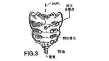
典型的には、腰椎、胸椎及び頸椎は、腹側本体若しくは椎体と背側弓若しくは神経弓とから構成される。胸部領域では、腹側本体は両側に肋骨の頭部を受け入れるための2つの肋骨窩を備えている。椎孔を取り囲む弓は、2本の脚と2枚の薄板から形成されている。脚は、両側で薄板と結合している椎体から後方向又は前方へ突き出ている骨性突起である。脚は椎弓根を形成している。椎弓は7個の突起を備えている。すなわち、1個の背棘突起、2個の外側横突起、及び4個の関節突起(2個の上関節突起と2個の下関節突起)である。弓の下境界線上の深くくぼんでいる下椎切痕は繊細な脊髄及び神経のための通路若しくは脊柱管を提供する。連続する椎孔が脊髄を取り囲んでいる。椎骨の関節突起は脊髄の後方へ延びている。
【0005】
連続する腰椎、胸椎及び頸椎の椎体は相互に関節式で連結しており、脊柱への圧縮力に対する緩衝作用及び減衰作用を提供する髄核である中央の塊を取り囲む線維性軟骨から形成された椎間板によって分離されている。椎間板は脊柱管の前方にある。下関節突起は尾側(即ち、足又は下方へ向かう)方向における次の連続する椎骨の上関節突起と関節式で連結している。数種の靭帯(棘上靭帯、棘間靭帯、前縦靭帯、後縦靭帯及び黄色靭帯)が、ある程度の限られた運動を許容しながら椎骨を正位置に保持している。
【0006】
脊椎の前方部分に位置する比較的に大きな椎体及び椎間板は脊柱の体重負荷サポートの大半を提供する。各椎体は、椎体の外面を備える比較的堅固な骨及び椎体の中心を備える脆弱な骨を有している。
【0007】
様々なタイプの脊柱障害が知られており、脊柱側弯症(脊柱の異常な側方湾曲)、脊柱後弯症(たいていは胸椎における、脊柱の異常な前方湾曲)、過剰前弯症(たいていは腰椎における、脊柱の異常な後方湾曲)、脊椎辷り症(通常は腰椎又は頸椎における、椎骨が他の椎骨へ被さる前方移動)、及び例えばぎっくり腰又は椎間板ヘルニア、変性椎間板疾患、骨折椎骨等がその他の障害が含まれる。そうした状態に苦しむ患者は通常、身体を衰弱させる極度の疼痛及びしばしば神経機能における神経学的欠損に直面する。
【0008】
脊椎手術のおよそ95%は、第4腰椎(「L4」)、第5腰椎(「L5」)と呼ばれる下方腰椎及び第1仙椎(「S1」)に関連している。持続性腰痛は、主としてL5とS1とを結合している椎間板の変性が原因である。この椎間板を除去して椎体を一緒に癒合させるため及び/又は椎間構造を安定化させるために外科処置が開発かつ使用されてきた。損傷した椎間板と椎体は高性能の診断的イメージング法を用いて確認することができるが、外科処置もまた高度の技術を要するため、一貫した満足の得られる臨床転帰を得ることができない。さらにその上、現在利用可能な癒合手術を受けた患者は重大な合併症を発生し、不快感を伴う回復期は長期に及ぶ。
【0009】
純然たる外科的技法の短所を克服するために、切除した椎間板及び/又は椎体の前方部分を強化又は置換するための脊柱インプラントの埋植術を含み、場合によっては治療された隣接椎骨の癒合に役立つように脊椎の領域を機械的に不動化する数多くの装置及び方法もまた長年に渡って使用又は提案されてきた。そのような方法は、上記の状態を効果的に治療し、患者が苦しんでいる疼痛を緩和するために使用されてきた。しかし、現在の固定用インプラント及び外科的埋植術には今もなお短所がある。そのようなインプラントの歴史的開発は、例えば米国特許第5,505,732号、第5,514,180号及び第5,888,223号に記載されている。
【0010】
脊椎固定のための1つの技術には、一般に脊椎と平行に走る多数の様々な形状の脊椎ロッドを使用することによる脊椎の不動化が含まれる。典型的には、脊椎の後面が分離され、最初に骨ネジが適切な椎骨の椎弓根又は仙骨へ締め付けられ、脊椎ロッドのための固定点として機能する。骨ネジは、棘突起の両側の各椎弓根に1本ずつ、一般に椎骨1個当たり2本が配置される。クランプ組立体は骨ネジへ脊椎ロッドを結合させる。脊椎ロッドは一般に、脊柱の所望の湾曲を達成するために曲げられる。ロッドを椎骨へ安定化させるためにワイヤーを使用することもできる。これらの技術は、例えば米国特許第5,415,661号に詳細に記載されている。
【0011】
これらのタイプのロッドシステムは有効であるが、後方アプローチをすること、及び治療される領域全体で各椎骨へネジ又はクランプを埋植することが必要になる。埋植されたシステムを十分に安定化させるために、椎弓根ネジを埋植するために治療される領域の上方の1個の椎骨及び下方の1個の椎骨がしばしば使用される。だが第2腰椎(L2)の上方の椎骨の椎弓根は極めて小さいので、小さな骨ネジしか使用することができず、これはときどき脊椎を安定化させるために必要なサポートを生じさせない。これらのロッドとネジ及びクランプ又はワイヤーは後方アプローチから脊椎に外科的に固定されるが、その処置は困難である。そのようなロッド組立体には大きな曲げモーメントが負荷され、さらにロッドは脊柱の外側に配置されるので、それらは付属コンポーネントの保持力を頼りとするのであるが、付属コンポーネントは椎骨から引き抜かれたり、引き離されたりする可能性がある。
【0012】
どちらも米国特許第5,735,899号に記載されている米国特許第4,553,273号及び第4,636,217号に開示されたこの方法の変形では、中央椎体の切開を通して上方及び下方椎体の内側へ外科的にアクセスすることによって3個の椎骨中2個が結合させられる。第’899号の特許では、これらのアプローチは「骨内」アプローチと呼ばれているが、中央椎体の除去による「骨間」アプローチと呼ぶ方がより適切である。この除去は、インプラントの両端を上方及び下方椎体内へ上向き及び下向きに推進できるように、それが占有するスペース内にインプラントを側方から挿入するのを可能にすることが必要である。これらのアプローチは第’899号特許では適切な内側−外側及び回転サポートを提供するのに失敗すると批判されている。第‘899号特許では、前方アプローチが実施され、上方及び下方椎骨内にスロットが作成され、ロッド端部がスロット内に適応させられ、側方へ延びているネジによって上方及び下方椎骨の残っている椎体へ取り付けられる。
【0013】
例えば米国特許第5,514,180号及び第5,888,223号に開示されているように、多数の椎間板形置換物若しくは人工椎間板インプラント及び挿入方法が提案されてきた。脊椎癒合術に臨床的に使用されてきたさらに他のタイプの椎間板強化若しくは増強インプラントは、外側にネジ切されていて2個の隣接椎骨間の椎間板内に形成された孔内に側方から適所へネジ入れられる中空シリンダー形チタン製ケージを備えている。死体若しくは骨盤からの骨移植片又は骨成長を促進する物質がその後、2個の隣接椎骨の融合を達成するためにケージ孔を通しての骨成長(又は内部成長)を促進するためにケージの中空中心内へ充填される。このような2個のケージインプラント及びそれらを配置するために使用する外科用ツールは、例えば米国特許第5,505,732号及び第5,700,291号に開示されている。ケージインプラント及び関連外科用ツール及びアプローチは、そのようなケージ各々のために2個の隣接する椎体間で側方に相当に大きな穴を正確にドリリングし、その後調製した各穴内にケージをネジ入れることを必要とする。1個以上の大きな穴は椎体の完全性を弱める可能性があり、さらに余りに後方にドリリングした場合は、脊髄を損傷させる可能性がある。極めて硬質の骨を備え、椎体に必要な強度を与えるのに役立つ椎体の端板は、通例はドリリング中に破壊されてしまう。1個以上のシリンダー形のケージは、椎体の残っている骨より硬く、さらに椎体は、崩れ又は「テレスコープ」して一緒になる傾向を示す。テレスコープすると、脊柱の長さの短縮を惹起し、さらに脊髄及び2個の隣接椎骨間を通過する神経の損傷を惹起する可能性がある。
【0014】
側方外科アプローチによって椎間板及び椎骨にアクセスするための方法及び装置は米国特許第5,976,146号に記載されている。介在する筋肉群又はその他の組織は、内視鏡視下での損傷した椎骨及び椎間板への側方からのアクセスを可能にするため及び修正外科処置を実施するために、第‘146号特許に開示されている空洞を形成して確保するツールセットによってバラバラに広げられる。
【0015】
上記の外科技法及び脊椎インプラントさらに臨床的に使用されてきたその他をまとめたものは、Joseph Y.Margoliesらによって編集された「Lumbosacral and Spinopelvic Fixation(腰仙部及び脊椎骨盤の固定)」と題する本の章の中に記載されている(Lippincott−Raven Publishers,フィラデルフィア、1996)。特に、第1、2、17、18、38、42及び44章を注目されたい。「Lumbopelvic Fusion(腰椎骨盤癒合術)」(Prof.Rene P.Louis,MDによる第38章)には、この場合にはS1に関連したL5及び椎間板の重度の位置ずれが生じている脊椎辷り症を修復するための技法が開示かつ描出されている。L5及びS1の前方側部が露出され、椎間板切除術が実施され、さらに位置ずれが重度の場合には、整復用ツールを使用してL5からS1への位置づけが機械的に修正される。L5を通ってS1内へ尾側方向へ延びるように形成された孔を通して、人工腓骨若しくは金属製ジュデット(Judet)スクリューがドエルとして挿入される。スクリューが使用される場合は、例えば患者から採取された骨のような骨成長材料がスクリューに平行して孔内へ挿入され、さらに椎間板の間隙はL5とS1との間の摘出された椎間板を塞ぐスペーサーインプラントとして機能するように椎骨面間にそれを保持できるようにスクリューへ縫合される骨が充填される。必要に応じて、外部ブリッジプレート又はロッドも挿入される。整復用ツールを用いて重度の脊椎辷り症の位置ずれを修正するためには後部側方若しくは前部側方アプローチが不可欠であるが、これは組織傷害を生じさせる。このアプローチ及び必要性のために、尾骨及び挿入されたジュデットスクリューはL5及びS1に交差するに過ぎない。
【0016】
脊椎辷り症を治療するための類似の前方アプローチは米国特許第6,056,749号に開示されている。このアプローチでは、ボアホールが頭寄り椎体に形成され、脊椎椎間板を通って尾側椎体内へ延ばされ、椎間板が切除され、椎間板間隙内へ側方からディスクケージが挿入され、さらに細長い中空のネジ切シャフトがボア内へディスクケージ内の穴を通って挿入される。ディスクケージは、採取された骨円板インサートの代わりとなり、シャフトとの連結交差は採取された骨円板インサートを上記で参照した出版物の第38章に開示された技法のスクリューへ結び付けるために使用される縫合糸の代わりとなる。
【0017】
上記の脊椎インプラントアプローチは、支持される、又は癒合される椎骨の前方若しくは後方部分を側方へ露出させる高度に侵襲性の手術を含んでいる。広範囲の筋肉剥離及び骨の調製が必要になる可能性がある。その結果として、脊柱はさらにいっそう弱化され、且つ/又は手術誘発性疼痛症候群を生じることがある。従って、現在使用又は提案されている下方腰椎を含む外科的固定及び癒合技法には数多くの欠点がある。余り重度ではない脊椎辷り症又は腰椎や仙椎及び椎間板に影響を及ぼす他の脊椎傷害又は欠損を修正するためには側方露出を回避するのが好ましい。
【0018】
脊椎辷り症を治療するための低侵入性後方アプローチは米国特許第6,086,589号に開示されているが、この場合には好ましくは椎骨を再アライメントした後に、露出された後方仙骨面から仙骨を通ってわずかに頭寄り方向でL5椎体内に直線状の孔が形成される。端部分へ限定された側面穴を備えた直線状の中空のスクリュー式シャフト及び骨成長材料がその孔の中に挿入される。好ましくはL5とS1との間の椎間板切除術が実施され、さらに好ましくは骨内部成長材料もまた頭寄り及び尾側椎体の間の間隙に挿入される。このアプローチによって、直線状の孔の遠位端と及びシャフトが接近してL5椎体の前面を穿孔する兆候を示すので、S1及びL5の限定されたアクセス及びアライメントだけを達成できる。
【0019】
折れた骨を安定化させるため、又は人工股関節、膝関節及び指関節を固定するために極めて多種多様な整形外科用インプラントが提案あるいは臨床使用されてきた。度々、ロッド若しくは関節サポートは例えば大腿骨のような細長い骨に形成された縦孔内に前後方向に配置される。細長いロッド及び吸収性セメントを使用して骨折した大腿骨又はその他の長骨を安定化させるための外科的方法は米国特許第5,514,137号に開示されている。いずれかの単一骨内へのロッドの配置を遂行するためには、骨端部が露出させられ、露出した端から他方の端へ通路がドリリングされる。その後、中空ロッドが挿入され、さらにロッドの遠位端とそのロッドを取り囲んでいる海綿質組織との間の固定を提供できるように中空ロッドを通して吸収性セメントが注入される。セメントを注入するためにはセメント注入装置もまた使用できる。同一方法で脊椎内に、又は脊椎に隣接してロッドを配置できる可能性については第’137号特許に短く触れられているが、特定のアプローチ又は装置は開示されていない。
【0020】
ドリリング用ツールは、椎骨内へ直線状の穴を穿孔するための上記の外科的処置の多くで使用されている。他の骨における湾曲した孔の穿孔については、例えば米国特許第4,265,231号、第4,541,423号、及び第5,002,546号に記載されている。第’231号特許は、縫合糸が孔の両開口端を通過するように骨内に湾曲した縫合糸保持開口端孔を穿孔するために使用される事前に湾曲化されたアウターシース内に取り囲まれている縦長のドリルドライブシャフトを記載している。第’546号特許は、骨を通る一定の湾曲路を穿孔するために回転式ロッカーアーム及びドリルビット用カーブドガイドを使用する複雑な曲線ドリリング用ツールを開示している。これらのアプローチはすべて、形成される湾曲した孔がアウターシース又はガイドの規定及び一定の湾曲に従うように指示する。シース又はガイドは、孔が形成されるにつれてその孔を通して前進させられるので、それが横切る骨の生理学的特徴を追跡するように孔の湾曲を使用者が調整することは不可能である。
【0021】
そこで本発明の好ましい実施形態は、外科的処置を実施するため、軸方向脊椎インプラントを受け入れるため、又は他の医学的理由のために脊椎の椎体を通る1つ以上の軸方向孔を形成するための装置に関する。そして、軸方向脊椎インプラントをアンカー止めするため、又はその中に供給される材料を収容するため、又はその他の目的のために、1個又は複数個の空洞を備えた軸方向孔が形成される。
【0022】
本発明の好ましい実施形態は、前方若しくは後方仙骨面の各前方若しくは後方目標点から少なくとも1個の仙椎椎体及び1個以上の腰椎椎体を通って頭寄り方向へ延びる前方及び後方TASIF軸方向孔をまず形成するための外科用ツールセットを含む装置に関する。それから、前側又は後側TASIF軸方向孔の1個又は複数個の選択した区間、たとえば頭部方向にあけられた穴の端、又はその穴に沿った円板スペースを広げてそこに空洞を設けるための穴拡大装置も使用される。空洞は、前側又は後側TASIF軸方向孔に挿入される軸方向脊椎インプラントをアンカー止めするための表面を提供したり、円板スペース又は椎体に形成されたその空洞内に置かれる材料を収容する、といったようなさまざまな目的に使用することができる。
【0023】
軸方向孔を形成するために、前仙骨面上の前方目標点は、仙骨前間隙を通る皮膚切開部から延びる経皮通路を使用してアクセスされる。各々前方若しくは後方目標点から1個以上の椎体を通って脊椎湾曲に従って頭寄り方向に延びる前方軸方向器具挿入/固定線(AAIFL)又は後方軸方向器具挿入/固定線(PAIFL)は、X線又は透視装置によって視認化される。好ましくは、湾曲した前方若しくは後方TASIF軸方向孔は、それぞれ視認化された各々AAIFL若しくはPAIFLと軸方向又は平行アライメントさせて形成される。但し、本発明は、湾曲した軸方向孔に限定されるものではない。
【0024】
単一の前方若しくは後方TASIF軸方向孔を形成する場合は、視認化された軸方向AAIFL及びPAIFLと軸方向又は平行アライメントさせて形成できる。同様に、複数の前方若しくは後方TASIF軸方向孔は、全部を視認化された軸方向AAIFL及びPAIFLと平行アライメントさせて、又はそうしたTASIF軸方向孔の少なくとも1つを、視認化された軸方向AAIFL及びPAIFLと軸方向アライメントさせて形成することができる。
【0025】
さらにその上、複数の前方若しくは後方TASIF軸方向孔は、全てが前方若しくは後方目標点から始まり、各TASIF軸方向孔が相互から離れて且つ視認化された軸方向AAIFL及びPAIFLから離れて分岐しながら頭寄り方向へ延びるように形成することができる。分岐しているTASIF軸方向孔は1個の頭寄り椎体又は別個の頭寄り椎体において間隔を開けて離れた場所で終了する。
【0026】
したがって、単一の前方若しくは後方TASIF軸方向孔の「アライメント」は、それぞれ視認化された軸方向AAIFL及びPAIFLとの同軸又は平行アライメントである。複数の前方若しくは後方TASIF軸方向孔のアライメントは、視認化された軸方向AAIFL及びPAIFLとの各々平行又は分岐アライメントのどちらかである。そのようなアライメントは、ここでは全てが軸方向と定義されている。
【0027】
ある実施形態では、視認化されたAAIFL及びPAIFLとアライメントさせて1個以上の仙椎椎体及び腰椎椎体を通って頭寄り方向へ延びるパイロット孔を形成するために同一の方法で径の小さい前方及び後方TASIF軸方向孔形成用ツールを使用できる。パイロット孔は、引続き前方及び後方TASIF軸方向孔を形成するために拡大される前方及び後方経皮通路の一部として使用することができる。
【0028】
本発明が先行技術において提示された困難を克服する方法の一部を指摘し、本発明を先行技術と識別するために本発明の前述の概要並びに本発明の長所及び特徴を本明細書において分かりやすく述べてきたが、いかなる意味においても最初に本特許出願において提示され、最終的に付与される請求項の解釈を制限するものとして作用することは意図されていない。
【0029】
本発明のこれら及びその他の長所及び特徴は、同様の参照番号が同一の構造を示している添付の図面とあわせて考慮に入れることにより、以下の好ましい実施形態の詳細な説明から容易に理解されるであろう。
【0030】
まず最初に、優先仮出願第60/182,748号から取り出された図1〜6の下記の説明に注目されたい。優先出願第60/182,748号において使用された頭字語TASF、AAFL及びPAFLは、本出願では、軸方向孔若しくはパイロット孔内へ挿入できる軸方向脊椎インプラントによって提供される癒合及び固定に加えて検査若しくは治療のために器具を導入できることを明示的に認識するために、本出願においてはTASIF、AAFIL及びPAFILへ変更されている。
【0031】
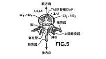
図1〜3は、脊柱の腰椎領域に関連して前方及び後方TASIF外科アプローチを略図的に示しており、さらに図4〜5は対応する後方TASIF軸方向孔22若しくは前方TASIF軸方向孔152又は対のTASIF軸方向孔221、222若しくは1521、1522内のTASIFインプラント又は対のTASIFインプラントの場所を示している。図5には、複数の、即ち2つ以上の同一物をAAIFL若しくはPAIFLと平行の並行関係で形成及び/又は使用できることを示すために、2つのTASIF軸方向孔及び軸方向脊椎インプラント若しくはロッドが示されている。図1〜3では前方及び後方経仙椎アクセスを提供し、図4及び5ではTASIF軸方向孔22若しくは152又は221、222若しくは1521、1522を形成する好ましいTASIF外科アプローチがさらに図面に示されている。好ましい経仙骨外科的アクセス及びTASIFパイロット孔形成用ツールは、さらに図面に示されている。
【0032】
図1の側面図には、尾骨、仙骨を形成している癒合した仙椎S1〜S5、及び上記の腰椎L1〜L5からなる脊柱の下方領域が示されている。ヒトの腰椎及び仙椎内に位置する一連の隣接椎骨は前方向、後方向及び軸方向を有しており、腰椎が、図1にD1〜D5と表示された無傷若しくは損傷した椎間板によって分離された。図2及び3は、仙骨及び尾骨の後方図及び前方図を示している。
【0033】
前方若しくは後方TASIF軸方向孔を形成するための方法及び装置は、まず最初に前仙骨位置、例えば図1及び3に示されたS1及びS2の接合点にある前方目標点に、又は後仙骨位置、例えば図1及び2に示されたS2の後方椎弓切除部位にアクセスすることを含んでいる。1本(又は1本以上)の視認化された、想像上の、軸方向器具挿入/固定線は、この図示された例ではL4及びL5である癒合すべき一連の隣接椎体を通って頭寄り方向及び軸方向に延びている。L4、D4、L5及びD5を通る視認化されたAAIFLは図1及び3に示されたS1に沿った前方目標点から比較的直線状に延びているが、しかし頭寄り方向で脊柱の湾曲に従うように湾曲してもよい。視認化されたPAIFLは、図1及び2に示されたS2の後方椎弓切除部位からより顕著な湾曲で頭寄り方向へ延びている。
【0034】
ここで、上記の視認下での仙骨前間隙を通る前方通路26を作製することは「Percutaneous Interventions in the Presacral Space:CT−guided Precoccygeal Approach−Early Experience(仙骨前間隙における経皮的インターベンション:CTガイド下尾骨前アプローチ−初期の経験)(Radiology 1999;213:901−904)」の中でJ.J.Trambert,MDによって記載された臨床技法によって証明されているように臨床的に実行可能であることを述べておかなければならない。
【0035】
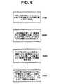
図6は、概略的に、図1〜3に示されている前方若しくは後方仙骨位置にアクセスし(S100)、後方及び前方TASIF軸方向孔を作製し(S200)、必要に応じて椎間板及び椎体を検査し、椎間板切除術、椎間板増強術、及び椎骨強化術を実施し(S300)、さらに後方及び前方軸方向脊椎インプラント及びロッドを埋植する(S400)外科ステップを簡単に示している。ステップS100では、図3の前方目標点又は図2の後方椎弓切除部位である前方若しくは後方仙骨位置へのアクセスが得られ、さらに作製しなければならない各軸方向孔のための開始点を提供するために前方若しくは後方仙骨位置に穿刺される。その後、一連の隣接椎骨の椎体及び椎間板を通って、PAIFL又はAAIFLのどちらかに沿って頭寄り方向及び軸方向に延びる軸方向孔が各穿刺点から穿孔される(S200)。軸方向孔は、ステップS300の処置を実施すべきかどうかを決定するために内視鏡を使用して視覚的に検査することができる。その軸方向孔を通って椎間板鏡検査又は椎間板切除術又は1個以上の椎間板の椎間板増強術又は椎体の脊椎作製術を実行できる(S300)。最後に、一連の隣接椎骨の椎体及び椎間板を通って頭寄り方向及び軸方向に延びるために細長いTASIF軸方向脊椎インプラント若しくはロッドが各軸方向孔内へ挿入される(S400)。ステップS400に代えて、上記のような治療を行なうため、又は疼痛を緩和するための他のタイプの軸方向脊椎インプラントを挿入することもできる。
【0036】
ステップS100は、好ましくは皮膚切開部から仙骨面の各前方若しくは後方目標点まで、又はある実施形態ではそれに被せて、若しくはそれを通過してさらに他の器具が導入されるパイロット孔の頭寄り端まで延びている前方若しくは後方経皮通路を作製するためにさらに他のツール及び器具の導入を可能にする前方若しくは後方経皮通路の作製を含んでいる。「前方仙骨前経皮通路」26(図1)は「仙骨前間隙」を通って仙骨まで前方へ延びている。後方経皮通路若しくは前方仙骨前経皮通路は、好ましくは1個以上の腰椎椎体及び存在する場合は椎間板を通って頭寄り方向に1つ以上の各後方若しくは前方TASIF孔を穿孔するために使用される。この関係での「経皮的(percutaneous)」は、他の医療技術からの特定処置を意味することなく、経皮的(transucutaneous又はtransdermal)におけると同様に、皮膚を通って後方又は前方目標点へ到達することを単純に意味している。経皮通路は一般に、X線若しくは透視装置によって視認化されるように各前方若しくは後方目標点から少なくとも1個の仙椎椎体及び1個以上の腰椎椎体を通って頭寄り方向に延びているAAIFL又はPAIFLと軸方向にアライメントしている。
【0037】
単一の前方若しくは後方TASIF孔は、好ましくは各視認化されたAAIFL若しくはPAIFLと軸方向にアライメントしており、さらに複数の前方若しくは後方TASIF孔は、好ましくは各視認化されたAAIFL若しくはPAIFLと平行にアライメントしている。軸方向脊椎インプラント及び椎間板切除術及び/又は椎間板及び/又は椎体増強術を実施するための器具を導入することは、経皮通路の用意及び1つ以上の前方若しくは後方TASIF孔の作製によって可能になる。
【0038】
ここで1つ以上の前方若しくは後方TASIF処置においてステップS100を実施するステップは前方及び/又は後方経皮通路の作製を完了するためにAAIFL及び/又はPAIFLをトラッキングするTASIF軸方向孔より径が小さなパイロット孔を穿孔するステップを含むことができる。ステップS300は必要に応じて、ステップ200におけるTASIF軸方向孔を作製するためのパイロット孔の拡大に続くよりも、ステップS100に続いてAAIFL/PAIFLパイロット孔を通して完了させることもできる。
【0039】
本発明の好ましい実施形態は、図4及び5に示されている視認化されたAAIFL及びPAIFLと軸方向にアライメントしている湾曲したパイロット孔又は湾曲した後方及び前方TASIF軸方向孔22若しくは152又は221...22n、若しくは1521...152nを形成するための外科用ツールセットを含む方法及び装置に関する。外科用ツールセットは、遠位ドリルシャフト区間に選択した湾曲を形成するために使用時に操作することができ、使用者が細長いドリルシャフト組立体の近位端から所望の穿孔面内へ湾曲した遠位セグメントを回転させることができるように十分なトルク能力を有する、例えば機械回転式ドリルビット、バーリング加工具、オーガー、研削器等(便宜的に、以下ではこれらを含めて、単にドリル・ビットと記述する)、あるいは各細長いドリル・シャフト・アセンブリーの遠位区間又は部分を真っ直ぐ伸ばしたり、これらの区間又は部分に選択した湾曲を作るために使用し、手で操作することができる同様の工具を含む。遠位部分を真っ直ぐ伸ばすときは、ドリルビットで真っ直ぐ穴をくり抜いて、TASIF軸方向孔の比較的真っ直ぐな区間を作る。次に、遠位部分が湾曲しているときは、TASIF軸穴の隣の区間に、TASIF軸穴のすでに穴をあけた区間より尾部側の区間に対して角度を成すように、ドリル・ビットで穴をあける。真っ直ぐな区間と湾曲した区間とを交互にくり返し拡張することによって、TASIFの軸方向孔は、全体として、上で述べたAAIFL又はPAIFLを追従する湾曲を形成する。
穿孔用ツールの第1実施例:
図7〜9は、図10〜18に示されている湾曲した視認化されたAAIFL若しくはPAIFLとアライメントさせた単一又は複数の湾曲した前方若しくは後方TASIF軸方向孔を穿孔するための1つの代表的穿孔用ツール10を示している。穿孔用ツール10は、1つの細長いドリルシャフト組立体12及びいかなる形状も取ることができるドリルモーター30(部分的に示されている)を備えている。ドリルモーター30が細長いドリルシャフト組立体12の近位端に永久的に取り付けられてその一部を形成できることは理解されるであろうが、ここでは別個の、取外式ドリルモーターとして図示されている。細長いドリルシャフト組立体12は、近位ドリルシャフト組立体端18の露出した近位ドライブシャフト端14と遠位ドリルシャフト組立体端24の露出したドリルビット20との間で延びている。露出した近位ドライブシャフト端14は、ドライブシャフト近位端から細長いドリルシャフト組立体の全長を通して露出した遠位ドリルビット20まで延びているドライブシャフト26を回転させるために技術においてよく知られている方法でドリルモーター30のチャック32内に受け入れられ、それに取り付けられている。露出した遠位ドリルビット20は、椎体の緻密かつ硬質の外骨膜及び緻密な骨層に穿通して相当に軟質の内側に位置する海綿質骨を通って前進するために適切な速度で回転できるバー若しくはオーガー若しくはスクリューのいずれかの形状を取ることができる。その後、ドリルビット20は穿通される各椎体の海綿質骨内に留まったままで各椎体及び椎間板の各対向面を穿孔しながら頭寄り方向に湾曲した経路で前進させられる。ドリルビット20は、好ましくはX線不透過性であるので、椎体を通るそれの前進は従来型イメージング装置を使用して観察することができる。
【0040】
細長いドリルシャフト組立体12はさらに、ドライブシャフト26を受け入れて取り囲むインナーシースルーメン36を有する前湾曲インナーシース34、インナーシース34を取り囲んでいるアウターシースルーメン42を有するアウターシース40、及びインナーシース34の近位端に取り付けられているハウジング16を備えている。アウターシース40は、インナーシース34の遠位セグメントが露出されるようにインナーシース34に被せて近位に引き戻すことができる、又はそれの遠位セグメントがアウターシースルーメン42内に取り囲まれるようにインナーシース34に被せて遠位へ伸ばすことができる。
【0041】
ドライブシャフト26は柔軟性かつ屈曲可能であり、単一フィラメント又はマルチフィラメントから作られた直線状若しくはコイル状ワイヤーから作製することができ、好ましくは従来型イメージング装置を使用して観察できるようにX線不透過性である。ドライブシャフト26の遠位端は、例えば図9に示されているように、ドリルビット20に対し、その近位面へ溶接することによって、又はドリルビット20の近位方向に延びているクリンプチューブ44のクリンプチューブルーメンの内側にクリンプすることによってなどのように、いずれかの方法によって取り付けられる。ドライブシャフト36の近位端は、図9に示されているように近位の露出したドライブシャフト端14から遠位方向に延びているさらに他のクリンプ若しくは溶接チューブ46内に受け入れられている。近位の露出したドライブシャフト端はハウジング16の近位端壁における軸受を通って延びており、それによってモーター30による回転のために支持される。
【0042】
ハウジング16及びドリルビット20の外径は直線状アウターシース40の外径より大きい。直線状アウターシース40は図7に示された近位位置、図9に示された遠位位置、及びハウジング16とドリルビット20によって拘束される任意の数の中間位置との間で前湾曲インナーシース34に被せて前後に動かすことができる。
【0043】
直線状アウターシース40は、好ましくはより柔軟性の前湾曲インナーシース34より相当に剛性が高くかつ長さが短い剛性の金属又はプラスチックから作製されている。より柔軟性の前湾曲インナーシース34は、プラスチック若しくは金属製の肉厚の薄いチューブから作製することができ、図7に示されているようにその遠位セグメントで例えば約90°のような適切な角度へ単一面で前湾曲させられる。この遠位セグメントの角度及び曲率半径はAAIFL又はPAIFLをトラッキングする必要を満たすためにアウターシース40の長さ及び剛性に応じて選択することができる。アウターシース40の剛性は、インナーシース34の遠位セグメントの湾曲を直線状にするために遠位方向へ前進させることを可能にするように選択される。しかし、アウターシース40は湾曲したTASIF軸方向孔がドリルビットによって作製されるにつれてその軸方向孔の領域内で屈曲又は湾曲させるのに十分な程度柔軟性である。この方法で、アウターシースは頭寄り方向に前進させたり、尾側方向に引き戻したりすることができ、さらになお湾曲したTASIF軸方向孔の湾曲に順応することができる。
後方TASIF軸方向孔の形成:
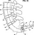
図10〜13は、図7〜9の穿孔用ツールを使用して図1及び2の視認化されたPAIFLと軸方向にアライメントさせて仙椎及び腰椎及び椎間板を通る後方TASIF軸方向孔22を形成するためのステップS200に含まれるステップを示している。同一ステップを使用して、ステップS200で拡大することのできる、ステップS100のパイロット孔を形成することができる。後方TASIF軸方向孔を形成するためにこの方法を使用する場合は、まず最初に径の小さな孔形成用ツール(例、径3.0mm)を使用してS1、L5及びL4を通る想像上の視認化されたPAIFL20に従って径の小さな湾曲したパイロット孔を穿孔する。その後、穿孔用ツールを抜去し、パイロット孔を通してネジ切り遠位ネジ込み式チップを有するガイドワイヤーを前進させてパイロット孔の尾側端及びL4帯の頭寄り部分内にネジ入れる。湾曲したガイドワイヤーをトラッキングできる柔軟な本体を有するオーバー・ザ・ワイヤー式孔拡大用ツールをガイドワイヤーの近位端に被せ、手動的又は機械的に回転させて、それに沿って前進させる。この方法で、小さなパイロット孔の径は例えば10.0mmの径のような径を有する前方TASIF軸方向孔22を形成するために拡大され、その後拡大用ツールが抜去される。
【0044】
椎体のサイズに比較した後方TASIF軸方向孔22の図示された径は単に模範例であること、及びパイロット孔及び穿孔用孔の径の範囲が各々約1〜10mm及び3〜30mmであってよいことが意図されていることは理解されるであろう。さらにその上、そのような複数の後方TASIF軸方向孔221...22nをPAIFLとほぼアライメントさせて並行関係で形成できることも理解されるであろう。
【0045】
図10では、仙骨の後面がステップS100において露出されている。患者の切開部位を取り囲む皮膚の領域は外科的に準備されており、肛門は粘着性ドレープを使用して手術野から除外されている。実際の皮膚穿刺部位はPAIFLをマッピングする腹臥位での術前CTスキャン又はMRI検査によって決定できる。ステップS100では、S2の後、仙骨面の上方の患者の皮膚に切開部が形成され、後方へ延びている、後仙骨面の骨梁を露出させるために皮下組織が剥離される。仙骨下方の後骨梁を通して小さな椎弓切除術14が実施される。椎弓切除術によって露出される包膜嚢及び神経根が静かに引っ込ませられ、脊柱管の末端部分が露出させられる。
【0046】
細長いドリルシャフト組立体12は、仙骨への最初の穿通が露出した仙骨面に対して実質的に直角となるように後方目標点でPAIFLと軸方向にアライメントさせられる。視認化されたPAIFL20に沿ってS2からTASIF軸方向孔をドリリング又は穿孔するためにドリルドライブシャフト組立体を受け入れるためのドリルガイドは、必要に応じてS2へ取り付けて、露出させた脊柱管及び皮膚切開部を通って後方へ伸ばすことができる。この開始位置で、インナーシース34を直線状にするために直線状のアウターシース40が十分遠位へ伸ばされ、さらに後方TASIF軸方向孔22の穿孔を開始するためにドリルビット20が回転させられる。このように、細長いドリルシャフト組立体12は、後方TASIF軸方向孔22の直線状のセグメント若しくは区間を形成するために前方へ前進する。
【0047】
ドリルビット20の進行は、従来型イメージング装置を使用して観察される。細長いドリルシャフト組立体12は前方向に伸ばされるので、図11に示されているように後方TASIF軸方向孔22の頭寄りセグメントに湾曲を導入する目的で頭寄り方向にインナーシースを湾曲させるためには直線状アウターシース34を近位方向へ引き戻すことが必要である。さらにまた、遠位セグメントの湾曲の面が脊椎の軸に対してアライメントするように近位ハウジング16を方向付けて保持することも必要である。図12に示すように、後側TASIF軸方向孔22の頭寄り部分の湾曲度は、フランジ50における真っ直ぐな外側シース40をフランジ50で近位及び遠位方向に移動させて湾曲した内側シース34の遠位部分の露出を幾分増減させることにより、連続的に調節される。この方法で、ドリルビット20は各椎体の海綿質骨内に留まったままで仙椎を通って頭寄り方向で腰椎椎体へ向かって前進する。理論的には、頭寄り方向へ脊椎のあらゆる数の椎体を通って穿孔することができる。
前方TASIF軸方向孔の作製:
図14〜16は、図7〜9の穿孔用ツールを使用して図1及び2の視認化されたPAIFLと軸方向にアライメントさせて仙椎及び腰椎及び椎間板を通る前方TASIF軸方向孔152を作製するためのステップS200に含まれるステップを示している。同一ステップを使用して、ステップS200で拡大することのできる、ステップS100のパイロット孔を作製することができる。椎体のサイズに比較して前方TASIF軸方向孔152の図示された径は単に模範例であること、及びパイロット孔及び穿孔用孔の径範囲が各々約1〜10mm及び3〜30mmである可能性があることが意図されていることは理解されるであろう。さらにその上、そのような複数の前方TASIF軸方向孔1521...152nをAAIFLとほぼアライメントさせて並行関係で作製できることも理解されるであろう。
【0048】
図14では、細長いドリルシャフト組立体12は、仙骨の最初の穿通が仙骨穿通面に対する頭側のS1及びL5の対向面に対して実質的に直角であるように、前方目標点でAAIFLと軸方向にアライメントしている。この前方仙骨面開始点に、尾骨に沿った患者の皮膚における切開部から通路作製用縫合糸若しくはツールを含んでいても含んでいなくてもよい前仙骨面に作製された経皮通路を通ってステップS100においてアクセスする。
【0049】
この開始位置では、インナーシース34を直線状にするために直線状のアウターシース40が十分遠位に延ばされるか、又はAAIFLへの最適な方向付けを提供するために患者の解剖学的構造に依存してわずかに引き戻される。前方TASIF軸方向孔152の穿孔を開始するためにドリルビット20が回転させられ、さらに後方TASIF軸方向孔22の比較的直線状の、又はわずかに湾曲したセグメントを作製するために細長いドリルシャフト組立体12が前方へ前進させられる。
【0050】
同様に、ドリルビット20の進行は従来型イメージング装置を使用して観察される。S1、D5(存在する場合)及びL5を通して頭寄り方向に細長いドリルシャフト組立体12を延ばすにつれて、図15に示されているように前方TASIF軸方向孔152の頭寄りセグメントにより程度の大きな湾曲を導入するために、インナーシースを頭寄り方向に湾曲させるために直線状のアウターシース34を近位へ引き戻すことが必要になる。同様に、さらにまた遠位セグメントの湾曲面が脊椎の軸に対してアライメントするように近位ハウジング16を方向付けて保持することも必要である。これは、近位ハウジング16上の外部参照マークを使用して遂行できる。前方TASIF軸方向孔152の頭寄りセグメントの湾曲の程度は、図15に示されているように湾曲したインナーシース34の遠位セグメントを多少露出させるための直線状アウターシース40の増加した近位及び遠位方向への移動によってフランジ50で持続的に調整される。この方法で、ドリルビット20は各椎体の海綿質骨内に留まったままで仙椎を通って頭寄り方向で腰椎椎体へ向かって前進する。
【0051】
前方TASIF軸方向孔152の全体的湾曲におけるわずかではあるが突然の角度変化は、アウターシース40の尾側引戻し及びインナーシース34の頭寄り前進によって、図15及び16に示されているようにL5及びL4の椎体内で作り出される。通常は椎間板間隙内又はより硬質の外側椎骨を通して穿孔する間におけるよりも、椎体の内部の海綿質骨内でドリルビット20の角度を調整する方が容易であることが予想されている。このため、海綿質の内骨を通して穿孔した後、椎間板の両側のより硬質の椎骨を通るドリルビット20の前進角度を直線状にするためにアウターシース40が遠位方向へ前進させられる。この直線状にされた穿孔進入角は例えば図17に示されているが、この場合、ドリルビット20はアウターシース40を頭寄り方向へ十分に前進させて椎体L4及びL5の対向面を越えて前進させられている。このプロセスは、前方TASIF軸方向孔152のより湾曲した区間とは異なる短い比較的に直線状の区間を生じさせる。従って、図18に示されている結果として生じる前方TASIF軸方向孔152は、脊椎の湾曲及び視認化されたAAIFLをトラッキングしている全体的湾曲を示しているが、曲率半径は変化しており、椎体L5及びL4の中央部分内では短い半径を示している。
他の代表的穿孔用ツール
図19〜21は、シース134の遠位セグメントに所望の湾曲を付与するために1本以上の先端配向ワイヤー104(図21)を使用する、ドリルモーター30及び細長いドリルシャフト組立体112を備える他の代表的実施形態に係る穿孔用ツール110を示している。シース134は、図9に示されたシース34の形態で遠位端124からハウジング124内へ延びているが、シース134はドライブシャフト126を受け入れるためのインナールーメン136及び先端配向ワイヤー104を受け入れるための径方向に偏在する先端配向ワイヤー用ルーメン102を取り囲んでいる。ドライブシャフト126の遠位端は、ドリルシャフト26の遠位端とドリルビット20との取り付けについての上記の形態でドリルビット120に取り付けられている。ドライブシャフト126の近位端は、ドライブシャフト26の近位端が近位の露出したドライブシャフト端14に取り付けられている形態で近位の露出したドライブシャフト端114に取り付けられている。ドライブシャフト126は、コイル状ワイヤー用ルーメンを通って延びているコアワイヤーを含む、若しくは含まない描出されたコイル状ワイヤー形を含むあらゆる形状を取ってよい。
【0052】
先端配向ワイヤー104は、遠位端124の取付点とハウジング138上に取り付けられた遠位セグメント湾曲コントロールリング106を備えるハウジング138内のアタッチメントとの間でドライブシャフトシース134の片側に沿って延びているワイヤー用ルーメンを通って延びている。接合部136に対して遠位にあるインナードライブシャフトシース134の遠位セグメントは、接合部136に対して近位にあるドライブシャフトシース134の近位セグメントより柔軟性である。遠位セグメント湾曲コントロールリング106は、ハウジングの柱面上方に位置しており、内側へ向かって延びている部材は、そこで先端配向ワイヤー104の近位端へ取り付けられているハウジング138における細長い溝108内へ延びている。図19及び20に示されているドライブシャフト遠位セグメントにおける湾曲を作製するための先端配向ワイヤー104の引戻しは、コントロールリング106を静止若しくはニュートラル位置から近位方向へスライドさせることによって実行されるが、このとき遠位セグメントは図19における破線で示されているように直線状の遠位セグメント形状134’を取る。ドライブシャフト126の遠位セグメントの長さ及びニュートラル位置からのコントロールリング106の運動範囲は、望ましいあらゆる角度若しくは範囲の湾曲を作製できるように選択できることは理解されるであろう。さらにその上、図19及び20に示された湾曲の反対側である遠位セグメントに湾曲を付与するためにコントロールリングをニュートラル位置から遠位方向へ押すことができるようにニュートラル位置からのコントロールリング106の運動範囲を選択できることも理解されるであろう。このため、先端配向ワイヤー104は引戻し専用のプルワイヤーであっても、引戻し及び延長用のプッシュプルワイヤーのいずれであってもよい。
【0053】
穿孔用ツール110は、図10〜18を参照して上記で説明したものと同一の形態で後方及び前方TASIF軸方向孔22及び152又は複数の同一軸方向孔を作製するために使用できる。後方及び前方TASIF軸方向孔22及び152の湾曲は、ドリルビット120が図10及び14に示された開始点から頭寄り方向に前進するにつれて、遠位セグメント湾曲コントロールリング106の操作によってコントロールされる。
さらに他の代表的穿孔用ツール
図22〜25は、ドリルモーター230及び細長いドリルシャフト組立体212を備える代表的穿孔用ツール210のさらに他の実施形態を示している。細長いドリルシャフト組立体212はさらにまた、ドライブシャフト226を受け入れて取り囲んでいるインナーシースルーメン236を有する直線状のインナーシース234、インナーシース234を取り囲んでいるアウターシースルーメン242を有する直線状アウターシース240、及びインナーシース234の近位端に取り付けられているハウジング238を備えている。この実施形態では、インナーシース234は必要に応じてあり、細長いドリルシャフト組立体212の全体の径を減少させるために省略することができる。
【0054】
ドライブシャフト226は、下記で説明するように使用時には遠位方向へ延ばしたときに直線状及び湾曲形のどちらにするにも十分に柔軟性かつ屈曲可能であり、従来型イメージング装置を使用して観察できるように好ましくはX線不透過性である単一フィラメント若しくはマルチフィラメントの直線状若しくはコイル状ワイヤーから作製することができる。ドライブシャフト226の遠位端は、例えば図23に示されているようにその近位面へ溶接することによって、又はドリルビット220の近位方向へ延びているクリンプチューブ244のクリンプチューブルーメンの内側にクリンプすることによって、というようにあらゆる形態で球形ドリルビット220へ取り付けられる。ドライブシャフト236の近位端は、図23に示されているように近位の露出したドライブシャフト端214から遠位方向へ延びているさらに他のクリンプ若しくは溶接チューブ246内に受け入れられる。近位の露出したドライブシャフト端214は、ハウジング238の近位端壁にある軸受を通って延びており、それによってモーター30による回転のために支持されている。
【0055】
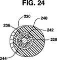
柔軟性アウターシース240は断面がほぼ円形であり、プッシュプル式近位ハンドル250とその遠位端との間で延びている。アウターシースルーメン242は、図23及び24に示されているように柔軟性アウターシース240の軸から偏らせてドリルビット220を配置するためにドリルシャフト226及び任意のインナーシース234がアウターシースルーメンを通って延びるように、柔軟性アウターシース240の軸から半径方向に偏っている。硬質プラスチック又は金属材料から作製されたスリーブ形のスラスト軸受228は、アウターシースルーメン242の遠位端開口部を取り囲んでそこからわずかに遠位方向へ突き出ているアウターシース遠位端に配置されている。アウターシース240の残りの露出した部分は、ドリルビット220によって作製された穴を通って前進させられるように柔軟性かつ圧縮性である。ハウジング238及びドリルビット220の外径は柔軟性アウターシース240の外径より大きい。柔軟性アウターシース240は図22に示された近位位置と図25に示された遠位位置との間でインナーシース234に被せて前後へ移動させることができる。ドリルビット220の外径は、図23及び24に示されているようにアウターシース240の外径とほぼ等しいか、又はそれよりわずかに大きい。
【0056】
径方向の偏り方向D(図23)に向かうアウター及びインナーシース240及び234の遠位セグメントにおける湾曲は、図25に示されているようにアウターシース240を十分な程度まで遠位方向へ前進させたときに作製される。スラスト軸受228の遠位面は、ハンドル250でアウターシース240を遠位方向へ押し、且つ/又はハウジング238でインナーシース234を近位方向へ引っ張ることによって、力を加えたときにドリルビット220の近位球面に対して支える。アウターシースルーメン242の軸方向偏り及びトラスト軸受228にすぐ近位でのアウターシース240の柔軟性は、協働してドリルビット220を径方向の偏り方向Dに向けて側方へ配向させる。径方向への偏り方向におけるアウターシース240の薄い肉厚はその軸方向圧縮及び図示された湾曲の誘発に寄与する。ドリルチップ220の角度配向及びアウター及びインナーシース240及び234の遠位セグメントの径方向への偏り方向Dへ向かう湾曲範囲は、材料の選択及びアウターシース240の軸からのアウターシースルーメン242の偏りによって選択することができる。
【0057】
穿孔用ツール210は、図10〜18を参照しながら上記で説明したのと同一形態で後方及び前方TASIF軸方向孔22及び152又は複数の同一軸方向孔を作製するために使用できる。後方及び前方TASIF軸方向孔22及び152の各区間の湾曲は、ドリルビット220が図10及び14に示された開始点から頭寄り方向に前進するにつれて、インナーシース234に対するアウターシース240の近位及び遠位操作によってコントロールする。
【0058】
TASIF軸方向孔若しくはパイロット孔穿孔用ツールの上記の実施形態は数多くの形態に変形できることは理解されるであろう。例えば、細長いドライブシャフト組立体は、TASIF軸方向孔内へそれの遠位端でフラッシング液をポンプ送出するため、及びフラッシング液及び骨破片を患者の身体の外部へ近位方向へ輸送するための液体ルーメンを提供するために変形することができる。さらに、細長いドライブシャフト組立体はガイドワイヤーに被せて前進させるために、その近位端から遠位端へ延びているガイドワイヤールーメンを提供するように変形することもできる。ガイドワイヤーに被せてドライブシャフトを回転させるための、適切なドライブモーター及びフラッシング能力を有するドライブシャフト組立体は、例えば米国特許第6,066,152号に開示されている。
【0059】
単一の後方若しくは前方TASIF軸方向孔22若しくは152を作製する場合は、上記のように視認化された軸方向AAIFL及びPAIFLと軸方向に若しくは平行にアライメントさせて作製することができる。同様に複数の後方若しくは前方TASIF軸方向孔は、全部を視認化された軸方向AAIFL及びPAIFLと平行にアライメントさせて、又は視認化された軸方向AAIFL及びPAIFLと軸方向アライメントで作製された少なくとも1つのそのようなTASIF軸方向孔を含めて作製することができる。
分岐しているTASIF軸方向孔:
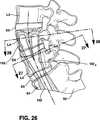
さらに、全部が図1〜3の前方若しくは後方目標点から開始して、相互に離れ且つ視認化された軸方向AAIFL及びPAIFLから離れて分岐しながら頭寄り方向へ延びる複数の前方若しくは後方TASIF軸方向孔を作製することができる。分岐しているTASIF軸方向孔は、1つの頭寄り椎体又は個別の複数の頭寄り椎体における間隔を開けて離れた場所で終了する。
【0060】
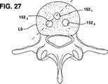
例えば、図25〜27は、前方目標点で開始して、ほばAAIFLの湾曲に従っているが外向きに分岐しながら頭寄り方向へ延びている共通尾側入口孔区間152’から穿孔された3つの前方TASIF軸方向孔1521、1522、1523からなる群を示している。共通入口孔区間からの分岐は、仙椎又はL5若しくはL4、又は孔がそれの中へ、又はそれを通って延びる他の頭寄り椎骨から開始できる。分岐しているTASIF軸方向孔1521、1522、1523の「三脚」は図26及び27に示されているように作製される。S1を通って、さらに椎間板D5及びL4の一部を横切る共通尾側入口孔区間は、その中への2つの細長い軸方向脊椎インプラントの挿入に適応するために分岐しているTASIF軸方向孔1521、1522、1523より径が大きくてよい。分岐しているTASIF軸方向孔1521、1522、1523の「三脚」内の細長い軸方向脊椎インプラントの挿入は実質的にL4、L5及びS1の固定を強化かつ増強できると考えられる。分岐しているTASIF軸方向孔1521、1522、1523は、図25〜27に示されているよりさらにいっそう延長させることができる。
軸方向脊椎インプラントをアンカー止めするためにくり抜かれる空洞:
このようにして、上に説明したツール・セットは、前述の一連の隣接椎骨及びあらゆる椎間板から成る椎体を貫通して前記軸方向癒合線と同じ線上に、頭部に向かって軸方向に、湾曲した経仙骨軸方向孔又は誘導穴をあけるために使用することができる。アライメントは、図4に示すように軸方向に行うことができ、図5に示すように並列的に行うこともでき、あるいは図25〜27に示すように分岐的に行うこともできる。さらに、上で説明したツールセットは、仙椎及び少なくとも一つの頭部側腰椎を貫通して比較的真っ直ぐな経仙骨軸方向孔を形成するために使用することもできる。空洞は、本発明に従って、比較的真っ直ぐか湾曲した経仙骨穴に形成される。
【0061】
空洞は、空洞を横切る前側又は後側TASIF軸方向孔22又は152の軸に対して垂直又はある角度を成すアンカー面が形成されるように椎骨又は椎間板の中へ外側に向かって延在することが好ましい。アンカー面は、外に向かって延びる細長い脊椎インプラントのアンカー部又は構造を前側又は後側TASIF軸方向孔22又は152内部の適切な位置に維持するため、それらを収容する。
【0062】
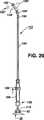
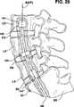
図29では、前側TASIF軸方向孔152は、椎体L3の中に延び、たとえば、前側TASIF軸方向孔152より直径が大きな拡張空洞154が、海綿質の中に形成される。前側TASIF軸方向孔152から外側に向かって延在する環状のアンカー面156を有する拡張空洞154を形成しうることが理解されよう。図示する拡張空洞154は、円筒形の樽状にくり抜かれるが、使用するツールによって、もっと球形又は半球形に近い形にすることもできる。図29に示すように、穴154をTASIFの軸方向孔の頭寄り終端と、もっと尾部寄りの椎体の両方に形成し得ると考えられる。
【0063】
さらに、椎間板スペースにまで延ばして、たとえば図29に示すように円板D5又はD4又はD3に形成し得ると考えられる。たとえば、円板状空洞154’が円板D4に描かれている。円板状空洞154’は、全体を円板D4内におさめ、L5及びL4の向かい合う椎体面を露出させるか、L5及び/又はL4の骨の中に延在することができる。
【0064】
拡張した空洞154、154’を作るには、穴を広げる切削ヘッドを装備した多様なツールを使用することができ、前側TASIF軸方向孔又は後側TASIF軸方向孔22を貫通して送りこまれ、作動させることができるツールであれば使用が可能である。切削ヘッドは頭寄り終端まで送られるか、軸方向孔の湾曲に適合することができる、細長くて柔軟な拡張ドライブシャフトを通して軸方向孔のもう一方の側に送られる必要がある。柔軟なツールドライブシャフトは、軸方向孔の範囲内を駆動され、典型的には回転して、切削ツールは、選択位置に空洞154、154’を拡張する。細長くて柔軟な拡張ドライブシャフト及び遠位切削ツールは、軸方向孔を貫通することによってその穴に案内されながら、空洞を形成する選択位置まで直接送ることができる。あるいは、前述のドライブシャフト及び前述の切削ツールは、柔軟な保護用外側シースを貫通し、且つ/又は軸方向孔の頭寄り終端のあらかじめ留置し脊椎骨に装着したガイドワイヤーを介して送ることができる。続いて、好ましくは柔軟なツールドライブシャフトを通じて、又は展開ワイヤーなどを操作して回転させながら、切削ツールを選択した位置に展開し、軸方向孔の外に向かって広げる。続いて、患者の体外の近位に装着した駆動モーターによって柔軟なツールドライブシャフトを回転させ、それによって切削ツールを回転させて海綿質又は円板体を切断又は研削し、穴径を広げて空洞を拡張する。空洞を形成したら、展開ワイヤーを手で操作するか、駆動モーターのスイッチを切ると同時に自動的に引き戻す。簡単にするため、以下に記述する好ましい拡張ツールの説明は、椎体内に空洞154を形成する場合について述べるが、円板状空洞154’を形成する場合にも適用できる。
(第1の模範的拡張ツール)
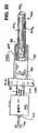
図30〜32は、細長くて柔軟なシース410のルーメン406の内部に収容されたドライブシャフト404の近位端に駆動モーター402が接続され、そのモーター駆動によって空洞を形成するツール400である。ドライブシャフト404は、ドライブシャフトルーメン412で形成され、該ルーメンは、駆動モーター402を介して駆動モーター402と接続するドライブシャフトから近位プルワイヤー・マニピュレーター416まで近位に向かって延びるプルワイヤー414を収容している。切削ツール・ルーメンを有する切削ヘッド420は、ドライブシャフトの遠位端418に接続され、そして遠位に向かって、前記ドライブシャフトの遠位端418から切削ツールの遠位端422まで延びている。プルワイヤー414の遠位端は、ドライブシャフトルーメンの遠位開口部から切削ツールルーメンを貫通して切削ツールの遠位端422との固定接続部まで延びている。
【0065】
切削ヘッド420は柔軟な肉薄金属管で形成され、前記金属管は縦方向に分割されてN個の切削ツールバンド4241〜424nを形成している。切削ツールバンド4241〜424nは、スプリング状を成しているが、通常は図30に描かれているように真っ直ぐな形態をとっている。空洞を形成するツール400は、後側又は前側TASIF軸方向孔22又は152を貫通して選択位置、たとえば最も頭部に近い腰椎体内部の頭寄り端まで、図30に描かれた形態で挿入される。
【0066】
次に、プルワイヤー414は、近位マニピュレーター416から近位に引かれ、第一の後退位置で固定され椎体の軟らかい海綿質内に空洞を拡張し始める。プルワイヤー414が切削ツールの遠位端422を引っ張ると、図31に示すように、N個の切削ツールバンド4241又は424nが外側に向かって弓状に湾曲する。続いて、プルワイヤー近位マニピュレーター416を、たとえばチャック機構によって正しい位置にロックし、駆動モーター402に通電してドライブシャフト404とプルワイヤー414とを相互に回転させることにより、切削ヘッド420を回転させる。周囲の椎骨が切削ツールバンド4241〜424nの鋭利な刃で切除され、切削ツールバンド4241〜424nは回転が止まるまで外側に向かって広がり続ける。プルワイヤー414はさらに近位まで後退させることができ、空洞をさらに大きく広げたいときは、図32に示すように、切削ツールバンド4241〜424nを外側に向かってさらに広げるように再設定することができる。
【0067】
空洞が所定の大きさに達したら切削ツールバンド4241〜424nの回転を停止させる。続いて、プルワイヤー414を解放して切削ヘッド420を図30に示す真っ直ぐな形に復帰させる。上記と同様にして、切削ツール400を外側又は前側TASIF軸方向孔22又は152の内部の、より尾部に近い位置から後退させるか、より尾部に近い位置まで後退させてより尾部に近い拡張空洞の空洞を形成する。
【0068】
切削ツール400は、たとえば形状、長さ、数及び切削ツールバンド4241〜424nに使用する材料を変えることによって多様に変化させることができる。さらに、切削ツールバンドを図30の形態から外側に広がった図31及び32の形態に押すために、プルワイヤーを使用することも可能であろう。
【0069】
さらに、駆動モーター402の電気を切って、切削ツールバンド4241〜424nの外側への広がりが増し、抵抗が生じるまで、近位マニピュレーター416をプルワイヤー414を自動的に引っ張る(あるいは、押しワイヤーの場合は押す)材料供給長さの計量ツールと交換することができる。
(第二の模範的拡張ツール)
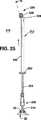
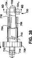
模式的に描いた駆動モーター502を細長く柔軟なシース510のルーメン506内部のドライブシャフト504の近位端に接続したさらに別の切削ツール500を図33及び34に示す。ドライブシャフト504は、ドライブシャフトルーメン512とで形成され、前記ルーメンは、駆動モーター502を介して駆動モーター502と接続するドライブシャフトから近位押しワイヤー・マニピュレーター516まで近位に向かって延びる押しワイヤー514を収容している。切削ツール・ルーメンを有する切削ヘッド520は、ドライブシャフトの遠位端518に接続され、そして遠位に向かって、前記ドライブシャフトの遠位端518から切削ツールの遠位端522まで延びている。
【0070】
切削ヘッド520は柔軟な肉薄金属管で形成され、前記金属管は縦長の間隙532を形成し、そして前記間隙532の長さ一杯に切削ツールワイヤー又はバンド524が延在している。切削ツールワイヤー又はバンドの遠位端は、遠位端522に、又はその近くで切削ヘッド520の内部に固定されている。押しワイヤー514の遠位端は、ドライブシャフトルーメン512の内部で切削ツールワイヤー又はバンド524の近位端に接続されている。切削ツールワイヤー又はバンド524は、スプリング様を成しているが、通常は図33に描かれているように、押しワイヤーマニピュレーター516が近位に向かって引かれているときは真っ直ぐな形態をとっている。空洞を形成するツール500は、後側又は前側TASIF軸方向孔22又は152を貫通して選択位置、たとえば最も頭部に近い腰椎体内部の頭寄り端まで、図33に描かれた形態で挿入される。
【0071】
次に、押しワイヤー514は、近位マニピュレーター516から遠位に向かって押され、引き延ばされた位置で固定され椎体の軟らかい海綿質内に空洞を拡張し始める。図34に示すように、押しワイヤー514は、切削ワイヤー又はバンド524を間隙532の外に向かって押し出す。切削ワイヤー又はバンド524は、超弾性金属合金などの材料で作ることができ、あらかじめ形成されたいくつかの屈曲部(bends or angles)を持ち、図34に示すように、その側面は、より矩形に近い横長な形状をしている。次に、押しワイヤー近位マニピュレーター516を、たとえばチャック機構によって正しい位置にロックし、駆動モーター502に通電してドライブシャフト504と押しワイヤー514とを共に回転させることにより、切削ヘッド520を回転させる。周囲の椎骨が切削ツールワイヤー又はバンド524の鋭利な刃で切除され、切削ツールワイヤー又はバンド524は回転が止まるまで外側に向かって広がり続ける。押しワイヤー514はさらに遠位に押し出すことができ、もし空洞をもっと大きく広げたいときは、切削ツールバンド又はワイヤー524をさらに外側に向かって広げるように再度設定することができる。
【0072】
空洞が所定の大きさに達したら切削ツール又はバンド524の回転を停止させる。続いて、押しワイヤー514を解放して切削ヘッド520を図33に示す真っ直ぐな形に復帰させる。上記と同様にして、切削ツール500を外側又は前側TASIF軸方向孔22又は152の内部の、より尾部に近い位置から後退させるか、より尾部に近い位置まで後退させてより尾部に近い拡張空洞の空洞を形成する。
(第三の模範的な拡張ツール)
模式的に描いた駆動モーター602を着脱が可能な細長く柔軟な外側シース610のルーメン606内部のドライブシャフト604の近位端に接続したさらに別の切削ツール600を図35及び36に示す。ドライブシャフトの遠位端618には切削ヘッド620が装着され、前記切削ヘッドは前記ドライブシャフト遠位端から切削ツールの遠位端622まで延在している。
【0073】
切削ヘッド620は、一本又は複数(N)本の研削ケーブル6241〜624nで形成され、前記ケーブルはドライブシャフトの遠位端のルーメン内に接合されるか、外部からクリンプされていて、その長さは比較的短い。研削ケーブル6241〜624nは、織られた金属又は編組された金属若しくは織布で作られ、研削化合物で被覆するか又は研削化合物を使って別の形態に形成することが好ましく、拘束されていないときは外側に向かってばねのように広がろうとする傾向を示す。
【0074】
図35に示すように、切削ツール620は、外側シースのルーメン606内に後退しながら、空洞154を作る位置まで前進する。次に、ハンドル又はグリップ616によって外側シース610を後退させると、研削ケーブル6241〜624nは外側に向かって展開する。駆動モーター602でドライブシャフト612を回転させると、研削ケーブル6241〜624nの自由端が周囲の椎骨にむち打つようにして研削する。ドライブシャフト612は後退させることもできるし、TASIF軸方向孔内部に展開して所望長さの空洞を形成することもできる。
【0075】
研削ケーブル6241〜624nは、ドライブシャフトの遠位端618から遠位に向かって遠在するように形成され、駆動モーター602でドライブシャフト612を回転させると、前記ケーブルは一本一本が個別に展開して周辺の骨に打ち当たる傾向を有する。しかし、研削ケーブル6241〜624nは、ドライブシャフト612に取り付けられ、ドライブシャフト612に対して直角に展開し、ルーメン606内に後退させるときにはドライブシャフトに巻き付くことが理解できよう。次に、研削ケーブル6241〜624nを解放すると、回転しながらドライブシャフト612の軸に対して側方に外側に向かって展開する傾向を有する。
(第四の模範的拡張ツール)
ナイフ、ルーテイング・ビット及び鋸歯など、柔軟なケーブルより剛直な穴あけエレメント又は切削エレメントを使用することができる。これらは、TASIF軸方向孔を通過するときには後退させ、それから受動的に又は能動的に外側に向かって展開して軸方向穿孔壁に拡張空洞を形成する。図37〜40は、図29に示すタイプのアンカー用空洞を形成するための拡張ツール700の模範的な形態を示す。図40に示すように、切削ヘッド720は交差する穴740に位置する一対の切削刃7241及び7242を含み、図37に示すように導入中は後退していて、図38〜40に示すように使用時には展開される。
【0076】
概略的に描かれた駆動モーター702は、ドライブシャフト704の近位端と接続され、前記ドライブシャフトは細長く柔軟なシース710のルーメン706内に収容されている。そして前記シースは図37に示す前進位置から図38〜40に示す後退位置まで動くことができる。ドライブシャフト704は、ドライブシャフトルーメン712とで形成され、前記ルーメンは、駆動モーター702から、切削ヘッド720との接続部718まで延在し、前記切削ヘッドはドライブシャフトの遠位端722まで延びている。ドライブシャフトルーメン712は、捻りワイヤ714を収容し、前記捻りワイヤはドライブシャフトの接続部から、近位に向かって駆動モーター702を通過し、近位の捻りワイヤマニピュレーター716まで延在する。捻りワイヤ714の遠位端はフォークのように分岐してピン742及び744を形成し、切削刃7241及び7242のそれぞれの穴746及び748をそれぞれ貫通して延びている。
【0077】
切削刃7241及び7242は、空洞を形成するツール400が、後側又は前側TASIF軸方向孔22又は152を貫通して選択位置、たとえば最も頭部に近い腰椎体内部の頭寄り端まで、図37に描かれた形態で挿入されるように、通常、穴740の内部に存在している。外側のシース710は、採用してもよいし採用しなくてもよいが、図37に示してあるように、後退させた切削刃7241及び7242を超えて延在する。
【0078】
次に、捻りワイヤ714を近位マニピュレーター716から捻って延伸した位置で固定し、椎体の軟らかい海綿質内部に空洞を拡張し始める。切削刃7241及び7242の鋭利な刃は、周辺の椎骨を切り取る。もし空洞をもっと大きく広げたいときは、穴あけの進行に合わせて切削刃7241及び7242をさらに外側に向かって広げるように、捻りワイヤ714をさらに捻ることができる。空洞が大きくなるのに合わせて、捻りワイヤ714が自動的に捻られるようにするため、近位マニピュレーター716を自動捻り機構に替えることができる。
【0079】
空洞が所定の大きさに達したら切削ヘッド720の回転を停止させる。続いて、捻りワイヤ714を反対方向に捻って切削刃7241及び7242を図37に示した後退位置まで後退させる。上記と同様にして、切削ヘッド720を外側又は前側TASIF軸方向孔22又は152の内部の、より尾部に近い位置から完全に引き抜くか、より尾部に近い位置まで後退させてより尾部に近い拡張空洞の空洞を形成する。
【0080】
切削刃7241及び7242を穴740の内部に後退させるか、穴740から延在させるには上で述べた以外の方法も可能である。ある別の実施態様では、切削刃7241及び7242を穴740の内部に緩く保持するか蝶番構造にして、ドライブシャフト704を駆動モーター702で回転させながら、遠心力によって、切削刃7241及び7242を外側に向かって展開させ、軟らかい海綿質を切り取ることができる。さらに別の方法では、穴740の内部に閉じ込めたばねによって遠心力を高めることができる。
(第五の模範的拡張ツール)
図41及び図42は、図29に示すタイプのアンカー用空洞を形成するための拡張ツール800の模範態様を示す。切削ヘッド820は細長い手鋤形ビット又はブレード824を含み、前記ビット又はブレードは、導入中及び引き抜き中の、図41に示すライン内に後退した形態及び図42に示す展開した位置から旋回する。細長いブレード824は、回転可能に支持されてドライブシャフトの遠位端818及び押しワイヤー814の遠位端に取り付けられ、切削刃832を動かして海綿質と接触したりこれから離れたりする。切削ブレード824の切削刃832に関して考えられるいくつかの形の例を図41及び42に示す。
【0081】
概略的に描かれた駆動モーター802は、ドライブシャフト804の近位端に接続され、前記ドライブシャフトは、細長く柔軟なシース810のルーメン806内部に収容され、そして前記シースは図41に示す前進した位置から図42に示す後退した位置まで動くことができる。外側のシース810は近位シースマニピュレーター826とシースの遠位端836の間に延在する。
【0082】
ドライブシャフト804は駆動ルーメン812とで形成され、前記ルーメンは、駆動モーター802から、切削ヘッド820との接続部818まで延在し、前記切削ヘッドはドライブシャフトの遠位端822まで延びている。ドライブシャフトルーメン812は、先端取り付けエレメントの向きを変えるためのワイヤー814を収容し、前記ワイヤーは、近位に向かって、ドライブシャフトと駆動モーター802との接続部から、駆動モーター802を通過して、先端取り付けエレメントの向きを変えるための近位マニピュレーター816まで延在している。先端取り付けエレメントの向きを変えるためのワイヤー814の遠位端は、回転可能な接続部を通してブレード824の近位の延長部834に接続される。
【0083】
ブレード824とドライブシャフト端822との間にピン及びスロットを備えたヒンジ30が形成される。ドライブシャフトルーメン812の内側には細長い間隙を有するフランジが形成され、ブレード824を貫通して穴が形成される。ヒンジのピンの近位端は細長い間隙に拘束され、ヒンジのピンの遠位端はブレードを貫通して形成された円形の穴に拘束される。切削刃832と海綿質とが角度を成すように切削ブレード824をヒンジ結合し広げる形態としては、多くの同等な形態をとることが可能である。
【0084】
切削ツールを使用するには、図41の後退位置で切削ブレード824を使って空洞が作られるべき、TASIF軸方向孔22又は152内部の位置に、切削ツール820を導入する。先端取り付けエレメントの向きを変えるためのワイヤー814を押すと、蝶番ピンの近位端は間隙をその遠位端に向かって滑動し、他方、蝶番ピンの遠位端は、円形穴の中で回転させ、その結果、図41に示す後退位置から図42に示す延びた位置まで、切削ブレード824を枢動する。次に、駆動モーター802に通電してドライブシャフト804及び延びた切削ブレード824を回転させる。ここで、先端取り付けエレメントの向きを変えるためのワイヤーのマニピュレーター816に、自動又は手動で押す力を加えると、切削ブレード824が回転して海綿質を切り去り、その結果、切削ブレードは、図41に示す後退位置から図42に示す一杯に延び切った位置まで、漸次伸展する。切削ツール820は、遠位にも近位にも移動することができ、形成される空洞の長さを伸ばし、形を作り出すことができる。
【0085】
空洞が所定の大きさと形が得られたら切削ヘッド820の回転を停止させる。先端取り付けエレメントの向きを変えるためのワイヤー814を近位に引っ張って、ヒンジのピンの近位端を間隙に沿ってその近位端まで滑動させ、他方、ヒンジのピンの遠位端を円形穴内部で回転させる。その結果、切削ブレード824は、図42の延伸位置から図41の後退位置まで枢動する。ここで空洞形成ツール800を後退させることができる。上記と同様にして、切削ヘッド820を、外側又は前側TASIF軸方向孔22又は152の内部の、より尾部に近い位置から完全に引き抜くか、より尾部に近い位置まで後退させてより尾部に近い拡張空洞の空洞を形成する。
(まとめ)
上記切削ヘッドの特徴は、相互に置き換えたり、一緒に組み合わせたりすることが可能であることは理解されよう。たとえば、研削材又は研削材で被覆し表面を鋭利な切削ブレードの刃で置き換えてもよいし、このような刃に加えてもよいし、切削ワイヤー表面に加えてもよい。
【0086】
上記の通りに図6のステップS200において作製される湾曲した後方及び前方TASIF軸方向孔22及び152は、仙骨において各後方及び前方目標点から始まり、上向き又は頭寄り方向へS1又はS2の椎体を通り、L5及びL4を含む頭寄り椎体を通り、さらに図1においてD4及びD5と表示された椎間板を通って延びる。椎間板D4及びD5は、通常は腰椎間で損傷又は変性しており、椎骨のインターベンション及び固定を必要とする患者が経験する疼痛を惹起する。後方又は前方TASIF軸方向孔22又は152の側面に沿った椎体及び椎間板の検査は、それを通して(又は事前に作製されている場合はパイロット孔を通して)挿入される細長い内視鏡を使用して行うことができる。椎間板除去術又は椎間板増強術及び/又は脊椎作製術は、患者の症状を緩和して軸方向脊椎インプラントの挿入によって達成される固定に役立たせるために、図6のステップS300に従って後方又は前方TASIF軸方向孔22又は152を通して実施できる。そのような処置では、材料又は器具は切除された椎間板間隙又は損傷した椎体に適合させるために湾曲した、後方及び前方TASIF軸方向孔22及び152を通して挿入することができる。
【0087】
上記で説明した湾曲した、後方及び前方TASIF軸方向孔22及び152内には様々な軸方向脊椎インプラントを挿入できることは理解されるであろう。そのような軸方向脊椎インプラントは側方から据え付けられる人工椎間板又は椎間板スペーサーと組合わせることができる。
【0088】
軸方向孔の内部に空洞を形成するための本発明の好ましい態様は、湾曲した軸方向孔に限定して記載してきたが、このような空洞を形成するための方法及び装置は、真っ直ぐか比較的真っ直ぐな軸方向孔の内部で有利に実施できることが理解できよう。さらに、このような空洞は、軸方向の穴の尾部側端に形成してもよいし、真っ直ぐな軸方向孔、湾曲した軸方向孔及び分岐した軸方向孔の頭寄り端と尾側端の中間の一個所又は複数個所に形成してもよいことが理解できよう。
【図面の簡単な説明】
【図1】 各々後方椎弓切除部位及び前方目標点から頭寄り方向及び軸方向に延びている視認化されたPAIFL及びAAIFLを描出している脊柱の腰椎及び仙椎部分の側方図である。
【図2】 各々後方椎弓切除部位及び前方目標点から頭寄り方向及び軸方向に延びている視認化されたPAIFL及びAAIFLを描出している脊柱の腰椎及び仙椎部分の後方図である。
【図3】 各々後方椎弓切除部位及び前方目標点から頭寄り方向及び軸方向に延びている視認化されたPAIFL及びAAIFLを描出している脊柱の腰椎及び仙椎部分の前方図である。
【図4】 図1〜3の視認化されたPAIFL及びAAIFLに従って作製されたTASIF軸方向孔内のTASIF軸方向脊椎インプラント若しくはロッドを描出している腰椎を一部断面で示す尾側から見た図である。
【図5】 図1〜3の視認化されたPAIFL及びAAIFLに対して平行に作製された類似の複数のTASIF軸方向孔内の複数の、例えば2個のTASIF軸方向脊椎インプラント若しくはロッドを描出している腰椎を一部断面で示す尾側から見た図である。
【図6】 経皮的に仙骨の後方若しくは前方目標点にアクセスするステップ、図1〜3の視認化されたPAIFL及びAAIFLに従った経皮通路を作製するステップ、並びにアクセスした椎体及び椎間板を治療するために1つ以上のTASIF軸方向孔を作製するステップ及び軸方向脊椎インプラントをその中に埋植するステップからなる引き続くステップを示している単純化されたフローチャートである。
【図7】 湾曲した前方若しくは後方TASIF軸方向孔を作製するための細長いドリルシャフト組立体及びドリルモーターを備える1つの代表的穿孔用ツール実施形態の平面図であり、このときドリルビットはアウターシースの引戻しによって細長いドリルドライブシャフト内に作製される90°湾曲を有している。
【図8】 アウターシースの調節によって細長いドリルシャフト組立体に作製された弱められた湾曲を有している図7の穿孔用ツールの平面図である。
【図9】 アウターシースをドリルビットの遠位端まで完全に遠位方向へ伸長させることによって湾曲が排除された図7及び8のドリルビットの断面図である。
【図10】 図7〜9の穿孔用ツールを使用して視認化された図1及び2のPAIFLと軸方向にアライメントさせた仙椎及び腰椎並びに椎間板を通る後方TASIF軸方向孔を作製するための1つの方法を示している部分的に断面を伴う側面図である。
【図11】 図7〜9の穿孔用ツールを使用して視認化された図1及び2のPAIFLと軸方向にアライメントさせた仙椎及び腰椎並びに椎間板を通る後方TASIF軸方向孔を作製するための1つの方法を示している部分的に断面を伴う側面図である。
【図12】 図7〜9の穿孔用ツールを使用して視認化された図1及び2のPAIFLと軸方向にアライメントさせた仙椎及び腰椎並びに椎間板を通る後方TASIF軸方向孔を作製するための1つの方法を示している部分的に断面を伴う側面図である。
【図13】 図7〜9の穿孔用ツールを使用して視認化された図1及び2のPAIFLと軸方向にアライメントさせた仙椎及び腰椎並びに椎間板を通る後方TASIF軸方向孔を作製するための1つの方法を示している部分的に断面を示伴う側面図である。
【図14】 図7〜9の穿孔用ツールを使用して視認化された図1及び2のPAIFLと軸方向にアライメントした仙椎及び腰椎並びに椎間板を通る前方TASIF軸方向孔を作製するための1つの方法を示している部分的に断面を伴う側面図である。
【図15】 図7〜9の穿孔用ツールを使用して視認化された図1及び2のPAIFLと軸方向にアライメントした仙椎及び腰椎並びに椎間板を通る前方TASIF軸方向孔を作製するための1つの方法を示している部分的に断面を伴う側面図である。
【図16】 図7〜9の穿孔用ツールを使用して視認化された図1及び2のPAIFLと軸方向にアライメントした仙椎及び腰椎並びに椎間板を通る前方TASIF軸方向孔を作製するための1つの方法を示している部分的に断面を伴う側面図である。
【図17】 図7〜9の穿孔用ツールを使用して視認化された図1及び2のPAIFLと軸方向にアライメントした仙椎及び腰椎並びに椎間板を通る前方TASIF軸方向孔を作製するための1つの方法を示している部分的に断面を伴う側面図である。
【図18】 図7〜9の穿孔用ツールを使用して視認化された図1及び2のPAIFLと軸方向にアライメントした仙椎及び腰椎並びに椎間板を通る前方TASIF軸方向孔を作製するための1つの方法を示している部分的に断面を伴う側面図である。
【図19】 図10〜18に図示された方法で湾曲した前方若しくは後方TASIF軸方向孔を作製するための細長いドリルシャフト組立体及びドリルモーターを備えるさらに他の代表的穿孔用ツール実施形態の図である。
【図20】 図10〜18に図示された方法で湾曲した前方若しくは後方TASIF軸方向孔を作製するための細長いドリルシャフト組立体及びドリルモーターを備えるさらに他の代表的穿孔用ツール実施形態の図である。
【図21】 図10〜18に図示された方法で湾曲した前方若しくは後方TASIF軸方向孔を作製するための細長いドリルシャフト組立体及びドリルモーターを備えるさらに他の代表的穿孔用ツール実施形態の図である。
【図22】 図10〜18に図示された方法で湾曲した前方若しくは後方TASIF軸方向孔を作製するための細長いドリルシャフト組立体及びドリルモーターを備えるさらに他の代表的穿孔用ツール実施形態の図である。
【図23】 図10〜18に図示された方法で湾曲した前方若しくは後方TASIF軸方向孔を作製するための細長いドリルシャフト組立体及びドリルモーターを備えるさらに他の代表的穿孔用ツール実施形態の図である。
【図24】 図10〜18に図示された方法で湾曲した前方若しくは後方TASIF軸方向孔を作製するための細長いドリルシャフト組立体及びドリルモーターを備えるさらに他の代表的穿孔用ツール実施形態の図である。
【図25】 図10〜18に図示された方法で湾曲した前方若しくは後方TASIF軸方向孔を作製するための細長いドリルシャフト組立体及びドリルモーターを備えるさらに他の代表的穿孔用ツール実施形態の図である。
【図26】 共通尾側区間から頭寄り方向に分岐して離れている複数の湾曲したTASIF軸方向孔の作製例を示している部分的に断面を伴う側面図である。
【図27】 複数の湾曲したTASIF軸方向孔の分岐を示している、図26の線27−27に沿う部分的断面を含む端面図である。
【図28】 複数の湾曲したTASIF軸方向孔の分岐を示している、図26の線28−28に沿う部分的断面を含む端面図である。
【図29】 尾側の終端に沿ってアンカーのための空洞を形成するために拡張した、TASIF軸方向孔の側面断面の一部である。
【図30】 図29に示したタイプのアンカーの穴を形成するための、拡張ツールの第一の代表例を示す。
【図31】 図29に示したタイプのアンカーの穴を形成するための、拡張ツールの第一の代表例を示す。
【図32】 図29に示したタイプのアンカーの穴を形成するための、拡張ツールの第一の代表例を示す。
【図33】 図29に示したタイプのアンカーの穴を形成するための、拡張ツールの第二の代表例を示す。
【図34】 図29に示したタイプのアンカーの穴を形成するための、拡張ツールの第二の代表例を示す。
【図35】 図29に示したタイプのアンカーの穴を形成するための、拡張ツールの第三の代表例を示す。
【図36】 図29に示したタイプのアンカーの穴を形成するための、拡張ツールの第三の代表例を示す。
【図37】 図29に示したタイプのアンカーの穴を形成するための、拡張ツールの第四の代表例を示す。
【図38】 図29に示したタイプのアンカーの穴を形成するための、拡張ツールの第四の代表例を示す。
【図39】 図29に示したタイプのアンカーの穴を形成するための、拡張ツールの第四の代表例を示す。
【図40】 図29に示したタイプのアンカーの穴を形成するための、拡張ツールの第四の代表例を示す。
【図41】 図29に示したタイプのアンカーの穴を形成するための、拡張ツールの第二の代表例を示す。
【図42】 図29に示したタイプのアンカーの穴を形成するための、拡張ツールの第二の代表例を示す。[0001]
The present invention generally relates to a device for use in spinal surgery, in particular a vertebral body in a minimally invasive, low traumatic manner, substantially coincident with the visualized transsacral axial instrument insertion / fixation (TASIF) line. And an apparatus for forming one or more shaped axial holes.
[0002]
It is estimated that 70% of adults have experienced significant back pain or chronic back pain spreading from the spinal column or spine area. Many people who suffer from chronic back pain or injuries that require immediate care seek help with surgical care to relieve their pain.
[0003]
The spine or spine surrounds the spinal cord and is made up of a series of 33 overlapping vertebrae, providing a flexible strut for the torso and head. The vertebra and sacral vertebra heading toward the head (ie head or upward) are separated by a disc made of fibrocartilage and joined by a joint capsule and a ligament. The top seven vertebrae are called cervical vertebrae, and the next 12 vertebrae are called thoracic vertebrae or dorsal vertebrae. The next five consecutive vertebrae below the thoracic vertebra are called lumbar vertebrae and are designated L1 to L5 in descending order. The next five consecutive vertebrae below the lumbar vertebra are called sacral vertebrae and are numbered S1 to S5 in descending order. The four vertebrae below the last sacrum are called caudal vertebrae. In adults, five sacral vertebrae coalesce to form a single bone called the sacrum, and four undeveloped caudal vertebrae coalesce to form another bone called the “coccyx”. The number of vertebrae may increase with additional vertebrae in one region, and sometimes one may be missing in another region.
[0004]
Typically, the lumbar, thoracic and cervical vertebrae are composed of a ventral body or vertebral body and a dorsal or neural arch. In the thoracic region, the ventral body is provided with two radial fossa for receiving the radial head on both sides. The arch surrounding the vertebral foramen is formed from two legs and two thin plates. The legs are osseous processes that protrude posteriorly or anteriorly from the vertebral bodies that are joined to the lamina on both sides. The leg forms a pedicle. The lamine has seven processes. That is, one dorsal spinous process, two lateral transverse processes, and four articular processes (two upper articular processes and two lower articular processes). A deeply depressed lower vertebral notch on the inferior border of the arch provides a passage or spinal canal for the delicate spinal cord and nerves. A continuous foramen surrounds the spinal cord. The articular process of the vertebra extends to the back of the spinal cord.
[0005]
Consecutive lumbar, thoracic and cervical vertebral bodies are articulated and formed from fibrous cartilage that surrounds the central mass, the nucleus pulposus that provides a buffering and damping action against compressive forces on the spinal column. Are separated by discs. The intervertebral disc is in front of the spinal canal. The inferior articular process is articulated with the upper articular process of the next successive vertebra in the caudal (ie, foot or downward) direction. Several types of ligaments (supraspinous ligament, interspinous ligament, anterior longitudinal ligament, posterior longitudinal ligament and yellow ligament) hold the vertebra in place while allowing some limited movement.
[0006]
The relatively large vertebral bodies and intervertebral discs located in the anterior portion of the spine provide the majority of spinal column weight bearing support. Each vertebral body has a relatively solid bone with the outer surface of the vertebral body and a fragile bone with the center of the vertebral body.
[0007]
Various types of spinal disorders are known: scoliosis (abnormal lateral curvature of the spine), kyphosis (usually in the thoracic vertebra, abnormal anterior curvature of the spine), excessive lordosis (usually in the lumbar spine) Abnormal posterior curvature of the spinal column), spondylosis (usually anterior movement of the vertebrae over the other vertebrae in the lumbar or cervical vertebrae), and other disorders such as tight hips or disc herniation, degenerative disc disease, fractured vertebrae, etc. included. Patients suffering from such conditions usually face extreme pain that often weakens the body and often neurological deficits in nerve function.
[0008]
Approximately 95% of spinal surgeries are associated with the lower lumbar vertebra, called the fourth lumbar vertebra ("L4"), the fifth lumbar vertebra ("L5"), and the first sacral vertebra ("S1"). Persistent low back pain is mainly due to degeneration of the intervertebral disc that connects L5 and S1. Surgical procedures have been developed and used to remove the intervertebral disc and fuse the vertebral bodies together and / or to stabilize the intervertebral structure. Damaged intervertebral discs and vertebral bodies can be identified using high-performance diagnostic imaging techniques, but surgical procedures are also highly technical and cannot provide consistently satisfactory clinical outcomes. Furthermore, patients who have undergone currently available fusion surgery will develop significant complications and the recovery period with discomfort will be long.
[0009]
To overcome the shortcomings of purely surgical techniques, including implants of spinal implants to strengthen or replace the anterior part of the resected disc and / or vertebral body, possibly healing of adjacent vertebrae that have been treated Numerous devices and methods for mechanically immobilizing the spinal region to help serve have also been used or proposed over the years. Such methods have been used to effectively treat the above conditions and relieve the pain suffering by patients. However, current fixation implants and surgical implantation still have shortcomings. The historical development of such implants is described, for example, in US Pat. Nos. 5,505,732, 5,514,180 and 5,888,223.
[0010]
One technique for spinal fixation involves immobilizing the spine by using a number of differently shaped spinal rods that typically run parallel to the spine. Typically, the posterior surface of the spine is separated and a bone screw is first clamped to the appropriate vertebra pedicle or sacrum, which serves as a fixation point for the spinal rod. There are typically two bone screws, one for each pedicle on either side of the spinous process, typically two per vertebra. The clamp assembly couples the spinal rod to the bone screw. The spinal rod is generally bent to achieve the desired curvature of the spinal column. A wire can also be used to stabilize the rod to the vertebra. These techniques are described in detail, for example, in US Pat. No. 5,415,661.
[0011]
These types of rod systems are effective, but require a posterior approach and the implantation of screws or clamps into each vertebra throughout the area to be treated. In order to sufficiently stabilize the implanted system, one vertebra above and one below the area to be treated for implanting the pedicle screw is often used. However, the pedicle of the vertebra above the second lumbar vertebra (L2) is so small that only small bone screws can be used, which sometimes does not provide the support necessary to stabilize the spine. These rods and screws and clamps or wires are surgically secured to the spine from the posterior approach, but the procedure is difficult. Such rod assemblies are loaded with large bending moments and the rods are placed outside the spinal column, so they rely on the retention of the accessory components, but the accessory components can be pulled out of the vertebrae. , May be pulled apart.
[0012]
In a variation of this method disclosed in US Pat. Nos. 4,553,273 and 4,636,217, both described in US Pat. No. 5,735,899, an incision is made through a central vertebral incision. And two of the three vertebrae are joined by surgical access to the inside of the lower vertebral body. In the '899 patent, these approaches are referred to as “intraosseous” approaches, but more appropriately referred to as “interbone” approaches with removal of the central vertebral body. This removal is necessary to allow the implant to be inserted laterally into the space it occupies so that both ends of the implant can be propelled upward and downward into the upper and lower vertebral bodies. These approaches are criticized in the '899 patent for failing to provide adequate medial-lateral and rotational support. In the '899 patent, an anterior approach is performed, slots are created in the upper and lower vertebrae, the rod ends are accommodated in the slots, and the upper and lower vertebrae remain with laterally extending screws. It is attached to the vertebral body.
[0013]
A number of disc replacements or artificial disc implants and insertion methods have been proposed, as disclosed, for example, in US Pat. Nos. 5,514,180 and 5,888,223. Yet another type of intervertebral disc augmentation or augmentation implant that has been used clinically for spinal fusions is in place from the side into a hole formed in the disc between the two adjacent vertebrae, threaded outward. It is equipped with a hollow cylinder type titanium cage that can be screwed into the screw. A bone graft from a cadaver or pelvis or a substance that promotes bone growth is then the hollow center of the cage to promote bone growth (or ingrowth) through the cage hole to achieve fusion of two adjacent vertebrae It is filled in. Two such cage implants and surgical tools used to place them are disclosed, for example, in US Pat. Nos. 5,505,732 and 5,700,291. Cage implants and related surgical tools and approaches accurately drill significantly larger holes laterally between two adjacent vertebral bodies for each such cage, and then screw the cage into each prepared hole. Need to put in. One or more large holes can weaken the integrity of the vertebral body and, if drilled too far back, can damage the spinal cord. Vertebral endplates, which contain extremely hard bones and help to provide the necessary strength to the vertebral body, are typically destroyed during drilling. One or more cylindrical cages are harder than the remaining bones of the vertebral body, and the vertebral bodies tend to collapse or “telescope” together. Telescopes can lead to shortening of the spinal column and further damage to the nerve that passes between the spinal cord and two adjacent vertebrae.
[0014]
A method and apparatus for accessing discs and vertebrae by a lateral surgical approach is described in US Pat. No. 5,976,146. The intervening muscle groups or other tissues are patented in the '146 patent to allow lateral access to the damaged vertebrae and discs endoscopically and to perform corrective surgical procedures. It is spread apart by a tool set that forms and secures the disclosed cavities.
[0015]
A summary of the above surgical techniques and spinal implants, as well as others that have been used clinically, is described in Joseph Y. et al. It is described in the chapter of the book, “Lumboscral and Spinopelvic Fixation” edited by Margolis et al. (Lippincott-Raven Publishers, Philadelphia, 1996). Note in
[0016]
A similar anterior approach for treating spondylolisthesis is disclosed in US Pat. No. 6,056,749. In this approach, a borehole is formed in the head vertebral body, extended through the spinal disc into the caudal vertebral body, the disc is excised, a disc cage is inserted laterally into the disc space, and an elongated hollow Threaded shaft is inserted into the bore through a hole in the disc cage. The disc cage replaces the harvested bone disc insert and the coupling intersection with the shaft is used to tie the harvested bone disc insert to the screw of the technique disclosed in Chapter 38 of the publication referenced above. An alternative to the sutures used.
[0017]
The spinal implant approach described above involves highly invasive surgery that exposes the anterior or posterior portion of the vertebrae to be supported or fused. Extensive muscle stripping and bone preparation may be required. As a result, the spinal column can be further weakened and / or produce surgically induced pain syndrome. Thus, there are a number of drawbacks to the surgical fixation and fusion techniques currently used or proposed including the lower lumbar spine. Side exposure is preferably avoided to correct less severe spondylosis or other spinal injuries or defects affecting the lumbar, sacral and intervertebral discs.
[0018]
A minimally invasive posterior approach for treating spondylolisthesis is disclosed in US Pat. No. 6,086,589, but in this case preferably from the exposed posterior sacral surface after realignment of the vertebrae. A straight hole is formed in the L5 vertebral body through the sacrum and slightly in the direction of the head. A straight, hollow screw shaft with a side hole limited to the end portion and bone growth material is inserted into the hole. Preferably a discectomy between L5 and S1 is performed, more preferably bone ingrowth material is also inserted into the gap between the head and caudal vertebral bodies. With this approach, only limited access and alignment of S1 and L5 can be achieved because the distal end of the straight hole and the shaft show signs of approaching and piercing the anterior surface of the L5 vertebral body.
[0019]
A great variety of orthopedic implants have been proposed or clinically used to stabilize broken bones or to fix hip, knee and finger joints. Often, the rod or joint support is placed in the anteroposterior direction in a longitudinal hole formed in an elongated bone such as the femur. A surgical method for stabilizing a fractured femur or other long bone using an elongated rod and resorbable cement is disclosed in US Pat. No. 5,514,137. To accomplish the placement of the rod within any single bone, the epiphysis is exposed and the passage is drilled from the exposed end to the other end. The hollow rod is then inserted and resorbable cement is injected through the hollow rod so as to provide further fixation between the distal end of the rod and the cancellous tissue surrounding the rod. A cement injection device can also be used to inject cement. Although the '137 patent is briefly touched on the possibility of positioning rods in or adjacent to the spine in the same way, no specific approach or device is disclosed.
[0020]
Drilling tools are used in many of the surgical procedures described above for drilling straight holes into vertebrae. Curved hole drilling in other bones is described, for example, in U.S. Pat. Nos. 4,265,231, 4,541,423, and 5,002,546. The '231 patent is enclosed within a pre-curved outer sheath that is used to pierce a suture holding open end hole that is curved into bone so that the suture passes through both open ends of the hole. The vertical drill drive shaft is described. The '546 patent discloses a complex curve drilling tool that uses a rotary rocker arm and a curved guide for a drill bit to drill a constant curved path through the bone. All of these approaches dictate that the curved holes that are formed follow the definition and constant curvature of the outer sheath or guide. As the sheath or guide is advanced through the hole as it is formed, it is impossible for the user to adjust the curvature of the hole to track the physiological characteristics of the bone it traverses.
[0021]
Thus, preferred embodiments of the present invention form one or more axial holes through the vertebral body of the spine for performing a surgical procedure, receiving an axial spinal implant, or for other medical reasons. Relates to a device for An axial bore with one or more cavities is then formed to anchor the axial spinal implant, to accommodate the material supplied therein, or for other purposes. .
[0022]
Preferred embodiments of the present invention include an anterior and posterior TASIF axis extending in a head-to-head direction from each anterior or posterior target point of the anterior or posterior sacral plane through at least one sacral vertebral body and one or more lumbar vertebral bodies. It relates to a device comprising a surgical tool set for first forming a directional hole. Then, one or more selected sections of the front or rear TASIF axial hole, such as the end of a hole drilled in the head direction, or a disk space along the hole, to provide a cavity there A hole enlarger is also used. The cavity provides a surface for anchoring an axial spinal implant that is inserted into the anterior or posterior TASIF axial hole, or contains material placed in that cavity formed in a disc space or vertebral body It can be used for various purposes such as.
[0023]
To form an axial hole, an anterior target point on the anterior sacral surface is accessed using a percutaneous passage that extends from a skin incision through the anterior sacral gap. An anterior axial instrument insertion / fixation line (AAIFL) or a posterior axial instrument insertion / fixation line (PAIFL) extending from the anterior or posterior target point through one or more vertebral bodies in the head direction according to the spinal curvature is X Visualized by a line or fluoroscopy device. Preferably, the curved front or rear TASIF axial hole is formed in axial or parallel alignment with each visualized AAIFL or PAIFL, respectively. However, the present invention is not limited to curved axial holes.
[0024]
When forming a single front or rear TASIF axial hole, it can be formed in axial or parallel alignment with the visualized axial directions AAIFL and PAIFL. Similarly, the plurality of anterior or posterior TASIF axial holes are all aligned in parallel with the visualized axial directions AAIFL and PAIFL, or at least one of such TASIF axial holes is visualized in the axial direction AAIFL. And can be formed in axial alignment with PAIFL.
[0025]
Furthermore, the plurality of front or rear TASIF axial holes all start from the front or rear target point, and each TASIF axial hole branches away from each other and from the visualized axial directions AAIFL and PAIFL. However, it can be formed to extend toward the head. Bifurcating TASIF axial holes terminate at spaced apart locations in one or separate head vertebral bodies.
[0026]
Thus, the “alignment” of a single front or rear TASIF axial hole is a coaxial or parallel alignment with the visualized axial directions AAIFL and PAIFL, respectively. The alignment of the plurality of front or rear TASIF axial holes is either parallel or branch alignment with each of the visualized axial directions AAIFL and PAIFL. All such alignments are defined herein as axial.
[0027]
In certain embodiments, the same diameter is reduced in a similar manner to form a pilot hole that is aligned with the visualized AAIFL and PAIFL to extend through one or more sacral and lumbar vertebral bodies. Front and rear TASIF axial hole forming tools can be used. The pilot holes can be used as part of anterior and posterior percutaneous passages that are subsequently expanded to form anterior and posterior TASIF axial holes.
[0028]
In order to point out some of the ways in which the present invention overcomes the difficulties presented in the prior art, and to distinguish the present invention from the prior art, the foregoing summary of the present invention and the advantages and features of the present invention are understood herein. Although briefly mentioned, it is not intended to limit the interpretation of the claims originally presented in this patent application and ultimately given in any way.
[0029]
These and other advantages and features of the present invention will be readily understood from the following detailed description of the preferred embodiments, when taken in conjunction with the accompanying drawings, in which like reference numerals indicate the same structure. It will be.
[0030]
First of all, note the following description of FIGS. 1-6 taken from priority provisional application 60 / 182,748. The acronyms TASF, AAFL and PAFL used in priority application 60 / 182,748 are used in this application in addition to the fusion and fixation provided by an axial spinal implant that can be inserted into an axial hole or pilot hole. In this application, changes have been made to TASIF, AAFIL, and PAFIL to explicitly recognize that an instrument can be introduced for examination or treatment.
[0031]
1-3 schematically illustrate an anterior and posterior TASIF surgical approach in connection with the lumbar region of the spinal column, and FIGS. 4-5 further illustrate corresponding posterior TASIF
[0032]
The side view of FIG. 1 shows the lower region of the spinal column consisting of the coccyx, the fused sacrum S1 to S5 forming the sacrum, and the lumbar vertebrae L1 to L5. A series of adjacent vertebrae located within the human lumbar and sacral vertebrae have anterior, posterior and axial orientations, and the lumbar vertebrae are separated by an intact or damaged disc labeled D1-D5 in FIG. It was. 2 and 3 show posterior and anterior views of the sacrum and coccyx.
[0033]
A method and apparatus for forming an anterior or posterior TASIF axial hole is first described at an anterior sacral position, eg, an anterior target point at the junction of S1 and S2 shown in FIGS. 1 and 3, or a posterior sacral position. For example, accessing the posterior laminectomy site of S2 shown in FIGS. One (or more) visualized, imaginary, axial instrument insertion / fixation line is headed through a series of adjacent vertebral bodies to be fused, L4 and L5 in this illustrated example. It extends in the offset direction and the axial direction. Visualized AAIFLs through L4, D4, L5 and D5 extend relatively straight from the anterior target point along S1 shown in FIGS. 1 and 3, but follow the curvature of the spinal column in a head-to-head direction It may be curved like this. The visualized PAIFL extends from the posterior laminectomy site of S2 shown in FIGS. 1 and 2 with a more pronounced curvature toward the head.
[0034]
Here, the creation of the
[0035]
FIG. 6 schematically accesses the anterior or posterior sacral position shown in FIGS. 1-3 (S100), creates posterior and anterior TASIF axial holes (S200), and intervertebral discs and vertebrae as needed. The surgical steps are briefly shown, examining the body, performing discectomy, disc augmentation, and vertebral augmentation (S300), and implanting posterior and anterior axial spinal implants and rods (S400). In step S100, access to the anterior target point of FIG. 3 or the anterior or posterior sacral location that is the posterior laminectomy site of FIG. 2 is obtained and a starting point is provided for each axial hole that must be created. In order to do this, it is punctured at the anterior or posterior sacral position. Thereafter, axial holes are drilled from each puncture point through the vertebral body and intervertebral disc of a series of adjacent vertebrae, extending axially and axially along either PAIFL or AAIFL (S200). The axial hole can be visually inspected using an endoscope to determine whether the procedure of step S300 should be performed. Through the axial hole, a discoscopic examination or discectomy or an intervertebral disc augmentation or vertebral spine preparation can be performed (S300). Finally, elongate TASIF axial spinal implants or rods are inserted into each axial bore to extend in a cephalad and axial direction through a series of adjacent vertebral vertebral bodies and discs (S400). As an alternative to step S400, other types of axial spinal implants may be inserted to perform treatment as described above or to relieve pain.
[0036]
Step S100 is preferably performed from the skin incision to each anterior or posterior target point of the sacral surface, or in some embodiments over or through it, the proximal end of the pilot hole where further instruments are introduced. It includes the creation of an anterior or posterior percutaneous passage that allows the introduction of additional tools and instruments to create an anterior or posterior percutaneous passage that extends to the front. The “anterior sacral percutaneous passage” 26 (FIG. 1) extends forward to the sacrum through the “pre-sacral gap”. The posterior percutaneous passage or anterior sacral percutaneous passage is preferably for drilling one or more respective posterior or anterior TASIF holes in the head direction through one or more lumbar vertebral bodies and, if present, the intervertebral disc. used. “Percutaneous” in this context does not imply specific treatment from other medical techniques, as in transcutaneous or transdermal, as well as posterior or anterior target points through the skin. It simply means getting to. A percutaneous passage generally extends from each anterior or posterior target point through at least one sacral vertebral body and one or more lumbar vertebral bodies, as viewed by an x-ray or fluoroscopy device, toward the head. Axially aligned with AAIFL or PAIFL.
[0037]
A single anterior or posterior TASIF hole is preferably axially aligned with each visualized AAIFL or PAIFL, and a plurality of anterior or posterior TASIF holes are preferably aligned with each visualized AAIFL or PAIFL. Aligned in parallel. Introducing an instrument for performing an axial spinal implant and discectomy and / or disc and / or vertebral augmentation is possible by providing a percutaneous passage and creating one or more anterior or posterior TASIF holes become.
[0038]
Here, performing step S100 in one or more anterior or posterior TASIF procedures is smaller in diameter than the TASIF axial hole tracking AAIFL and / or PAIFL to complete the creation of the anterior and / or posterior percutaneous passages. Drilling a pilot hole can be included. Step S300 can optionally be completed through the AAIFL / PAIFL pilot hole following step S100, rather than following the enlargement of the pilot hole to create the TASIF axial hole in step 200.
[0039]
Preferred embodiments of the present invention include curved pilot holes or curved rear and front TASIF
First example of drilling tool:
7-9 are one representative for drilling single or multiple curved anterior or posterior TASIF axial holes aligned with the curved visualized AAIFL or PAIFL shown in FIGS. A
[0040]
The elongate
[0041]
The
[0042]
The outer diameter of the
[0043]
The linear
Formation of the rear TASIF axial hole:
FIGS. 10-13 show a posterior TASIF
[0044]
The illustrated diameter of the posterior TASIF
[0045]
In FIG. 10, the posterior surface of the sacrum is exposed in step S100. The area of skin surrounding the patient's incision site is surgically prepared and the anus is removed from the surgical field using an adhesive drape. The actual skin puncture site can be determined by preoperative CT scan or MRI examination in the prone position mapping PAIFL. In step S100, after S2, an incision is made in the patient's skin above the sacral surface, and the subcutaneous tissue is exfoliated to expose the trabecular bone of the posterior sacral surface extending backward. A
[0046]
The elongate
[0047]
The progress of the
Creating the front TASIF axial hole:
FIGS. 14-16 illustrate an anterior TASIF
[0048]
In FIG. 14, the elongate
[0049]
In this starting position, the straight
[0050]
Similarly, the progress of the
[0051]
A slight but sudden change in angle in the overall curvature of the front TASIF
Other typical drilling tools
FIGS. 19-21 include a
[0052]
The
[0053]
The
Still other typical drilling tools
22-25 illustrate yet another embodiment of an
[0054]
The
[0055]
The flexible
[0056]
The curvature in the distal segment of the outer and
[0057]
The
[0058]
It will be appreciated that the above-described embodiment of the TASIF axial hole or pilot hole drilling tool can be varied in many forms. For example, the elongate drive shaft assembly is for pumping flushing fluid at its distal end into the TASIF axial bore and for transporting flushing fluid and bone debris proximally out of the patient's body. It can be deformed to provide a liquid lumen. Further, the elongate drive shaft assembly may be modified to provide a guide wire lumen extending from its proximal end to its distal end for advancement over the guide wire. A drive shaft assembly with suitable drive motor and flushing capability for rotating the drive shaft over a guide wire is disclosed, for example, in US Pat. No. 6,066,152.
[0059]
When the single rear or front TASIF
Branched TASIF axial hole:
Further, a plurality of front or rear TASIF shafts starting from the front or rear target point of FIGS. 1 to 3 and extending in the head direction while branching away from each other and visualized axial directions AAIFL and PAIFL Directional holes can be made. Bifurcating TASIF axial holes terminate at spaced apart locations in one head vertebral body or individual head vertebral bodies.
[0060]
For example, FIGS. 25-27 are perforated from a common caudal
Cavity hollowed out to anchor the axial spinal implant:
In this way, the tool set described above passes through the vertebral body comprising the aforementioned series of adjacent vertebrae and any intervertebral disc, on the same line as the axial fusion line, axially towards the head, Can be used to drill curved transsacral axial holes or guide holes. Alignment can be performed in the axial direction as shown in FIG. 4, can be performed in parallel as shown in FIG. 5, or can be performed in branches as shown in FIGS. Furthermore, the tool set described above can also be used to form a relatively straight transsacral axial hole through the sacrum and at least one cephalad lumbar vertebra. The cavity is formed in a relatively straight or curved transsacral hole in accordance with the present invention.
[0061]
The cavity extends outwardly into the vertebra or disc so that an anchor plane perpendicular to or at an angle to the axis of the anterior or posterior TASIF
[0062]
In FIG. 29, the anterior TASIF
[0063]
Furthermore, it is considered that it can be extended to the intervertebral disc space and formed into a disc D5 or D4 or D3 as shown in FIG. 29, for example. For example, a disk-shaped
[0064]
To create the expanded
(First exemplary extension tool)
FIGS. 30-32 show a
[0065]
The cutting
[0066]
The
[0067]
When the cavity reaches a predetermined size, the
[0068]
The
[0069]
Further, the
(Second exemplary extension tool)
A
[0070]
The cutting
[0071]
The
[0072]
When the cavity reaches a predetermined size, rotation of the cutting tool or
(Third exemplary extension tool)
A
[0073]
The cutting
[0074]
As shown in FIG. 35, the
[0075]
Grinding cable 6241 ~ 624n Is formed to be distally away from the
(Fourth exemplary extension tool)
Drilling or cutting elements that are more rigid than flexible cables, such as knives, routing bits, and saw teeth, can be used. These are retracted as they pass through the TASIF axial hole, and then passively or actively deploy outward to form an expansion cavity in the axial perforation wall. FIGS. 37-40 illustrate an exemplary configuration of an
[0076]
A schematically depicted
[0077]
Cutting
[0078]
The
[0079]
When the cavity reaches a predetermined size, the rotation of the cutting
[0080]
Cutting
(Fifth exemplary expansion tool)
41 and 42 show an exemplary embodiment of an
[0081]
A schematically depicted drive motor 802 is connected to the proximal end of the
[0082]
The
[0083]
A
[0084]
To use the cutting tool, the
[0085]
When the cavity has a predetermined size and shape, the rotation of the cutting
(Summary)
It will be understood that the features of the cutting heads can be interchanged with each other or combined together. For example, it may be coated with an abrasive or an abrasive and the surface may be replaced with a sharp cutting blade, or may be added to such a blade, or may be added to the cutting wire surface.
[0086]
As described above, the curved posterior and anterior TASIF
[0087]
It will be appreciated that various axial spinal implants can be inserted into the curved, posterior and anterior TASIF
[0088]
Although the preferred embodiment of the present invention for forming a cavity inside an axial hole has been described limited to curved axial holes, methods and apparatus for forming such a cavity are straightforward or comparable. It can be seen that it can be advantageously carried out inside a straight axial hole. Further, such cavities may be formed at the tail end of the axial hole, or at the head and tail ends of straight axial holes, curved axial holes and branched axial holes. It will be understood that it may be formed at one or more intermediate points.
[Brief description of the drawings]
FIG. 1 is a side view of a lumbar and sacral portion of a vertebral column depicting visualized PAIFL and AAIFL extending from the posterior laminectomy site and an anterior target point, respectively, in the head and axial directions. .
FIG. 2 is a posterior view of the lumbar and sacral portions of the spine depicting the visualized PAIFL and AAIFL extending from the posterior laminectomy site and the anterior target point, respectively, in the head and axial directions.
FIG. 3 is an anterior view of the lumbar and sacral portions of the vertebral column depicting visualized PAIFL and AAIFL extending head-to-head and axially from the posterior laminectomy site and anterior target point, respectively.
4 is a caudal view of the lumbar spine showing a TASIF axial spinal implant or rod in a TASIF axial bore made in accordance with the visualized PAIFL and AAIFL visualized in FIGS. FIG.
FIG. 5 depicts multiple, for example, two TASIF axial spinal implants or rods in similar multiple TASIF axial bores made parallel to the visualized PAIFL and AAIFL of FIGS. 1-3. It is the figure which looked at the lumbar vertebra which is doing from the caudal side which shows a partial cross section.
FIG. 6 Percutaneously accessing the posterior or anterior target point of the sacrum, creating a percutaneous passage according to the visualized PAIFL and AAIFL of FIGS. 1-3, and the accessed vertebral body and disc 6 is a simplified flow chart showing subsequent steps consisting of creating one or more TASIF axial bores for implanting and implanting an axial spinal implant therein.
FIG. 7 is a plan view of one exemplary drilling tool embodiment comprising an elongate drill shaft assembly and a drill motor for creating a curved front or rear TASIF axial hole, wherein the drill bit is an outer sheath With a 90 ° curvature created in the elongated drill drive shaft.
8 is a plan view of the drilling tool of FIG. 7 having a weakened curvature created in an elongated drill shaft assembly by adjustment of the outer sheath.
9 is a cross-sectional view of the drill bit of FIGS. 7 and 8 with the curvature eliminated by extending the outer sheath completely distally to the distal end of the drill bit. FIG.
10 for creating a posterior TASIF axial hole through the sacral and lumbar vertebrae and the intervertebral disc axially aligned with the PAIFL of FIGS. 1 and 2 visualized using the drilling tool of FIGS. FIG. 2 is a side view with a partial cross-section illustrating one method.
11 to create a posterior TASIF axial hole through the sacral and lumbar vertebrae and the intervertebral disc axially aligned with the PAIFL of FIGS. 1 and 2 visualized using the drilling tool of FIGS. FIG. 2 is a side view with a partial cross-section illustrating one method.
12 for creating a posterior TASIF axial hole through the sacral and lumbar vertebrae and the intervertebral disc axially aligned with the PAIFL of FIGS. 1 and 2 visualized using the drilling tool of FIGS. FIG. 2 is a side view with a partial cross-section illustrating one method.
13 to create a posterior TASIF axial hole through the sacral and lumbar vertebrae and the intervertebral disc axially aligned with the PAIFL of FIGS. 1 and 2 visualized using the drilling tool of FIGS. FIG. 6 is a side view with a partial cross-section illustrating one method.
14 for creating an anterior TASIF axial hole through the sacral and lumbar vertebrae and an intervertebral disc axially aligned with the PAIFL of FIGS. 1 and 2 visualized using the drilling tool of FIGS. FIG. 6 is a side view with a partial cross section illustrating one method.
15 for creating an anterior TASIF axial hole through the sacral and lumbar vertebrae and an intervertebral disc axially aligned with the PAIFL of FIGS. 1 and 2 visualized using the drilling tool of FIGS. FIG. 6 is a side view with a partial cross section illustrating one method.
16 for creating an anterior TASIF axial hole through the sacral and lumbar vertebrae and an intervertebral disc axially aligned with the PAIFL of FIGS. 1 and 2 visualized using the drilling tool of FIGS. FIG. 6 is a side view with a partial cross section illustrating one method.
17 for creating an anterior TASIF axial hole through the sacral and lumbar vertebrae and an intervertebral disc axially aligned with the PAIFL of FIGS. 1 and 2 visualized using the drilling tool of FIGS. FIG. 6 is a side view with a partial cross section illustrating one method.
18 for creating an anterior TASIF axial hole through the sacral and lumbar vertebrae and an intervertebral disc axially aligned with the PAIFL of FIGS. 1 and 2 visualized using the drilling tool of FIGS. FIG. 6 is a side view with a partial cross section illustrating one method.
FIG. 19 is a view of yet another exemplary drilling tool embodiment comprising an elongate drill shaft assembly and a drill motor for creating a curved forward or posterior TASIF axial hole in the manner illustrated in FIGS. 10-18. It is.
FIG. 20 is a view of yet another exemplary drilling tool embodiment comprising an elongate drill shaft assembly and a drill motor for creating a curved front or rear TASIF axial hole in the manner illustrated in FIGS. 10-18. It is.
FIG. 21 is a view of yet another exemplary drilling tool embodiment comprising an elongate drill shaft assembly and a drill motor for creating a curved forward or posterior TASIF axial hole in the manner illustrated in FIGS. It is.
FIG. 22 is a view of yet another exemplary drilling tool embodiment comprising an elongate drill shaft assembly and drill motor for creating a curved forward or rearward TASIF axial hole in the manner illustrated in FIGS. 10-18. It is.
FIG. 23 is a view of yet another exemplary drilling tool embodiment comprising an elongate drill shaft assembly and drill motor for creating a curved forward or rearward TASIF axial hole in the manner illustrated in FIGS. 10-18. It is.
FIG. 24 is a view of yet another exemplary drilling tool embodiment comprising an elongate drill shaft assembly and a drill motor for creating a curved forward or rearward TASIF axial hole in the manner illustrated in FIGS. 10-18. It is.
FIG. 25 is a view of yet another exemplary drilling tool embodiment comprising an elongate drill shaft assembly and a drill motor for creating a curved forward or posterior TASIF axial hole in the manner illustrated in FIGS. 10-18. It is.
FIG. 26 is a side view with a partial cross section showing an example of making a plurality of curved TASIF axial holes branching away from a common caudal section in a head-to-head direction.
FIG. 27 is an end view including a partial cross section taken along line 27-27 of FIG. 26 showing the branching of a plurality of curved TASIF axial holes.
FIG. 28 is an end view including a partial cross-section taken along line 28-28 of FIG. 26 showing the branching of a plurality of curved TASIF axial holes.
FIG. 29 is a portion of a side cross-section of a TASIF axial hole that has been expanded to form a cavity for an anchor along the caudal termination.
30 shows a first representative example of an expansion tool for forming an anchor hole of the type shown in FIG. 29. FIG.
31 shows a first representative example of an expansion tool for forming an anchor hole of the type shown in FIG. 29. FIG.
FIG. 32 shows a first representative example of an expansion tool for forming an anchor hole of the type shown in FIG.
33 shows a second representative example of an expansion tool for forming an anchor hole of the type shown in FIG. 29. FIG.
34 shows a second representative example of an expansion tool for forming an anchor hole of the type shown in FIG. 29. FIG.
35 shows a third representative example of an expansion tool for forming an anchor hole of the type shown in FIG. 29. FIG.
36 shows a third representative example of an expansion tool for forming an anchor hole of the type shown in FIG. 29. FIG.
FIG. 37 shows a fourth representative example of an expansion tool for forming an anchor hole of the type shown in FIG.
FIG. 38 shows a fourth representative example of an expansion tool for forming an anchor hole of the type shown in FIG.
39 shows a fourth representative example of an expansion tool for forming an anchor hole of the type shown in FIG. 29. FIG.
40 shows a fourth representative example of an expansion tool for forming an anchor hole of the type shown in FIG. 29. FIG.
FIG. 41 shows a second representative example of an expansion tool for forming an anchor hole of the type shown in FIG.
42 shows a second representative example of an expansion tool for forming an anchor hole of the type shown in FIG. 29. FIG.
Claims (13)
Translated fromJapanese前記軸方向器具挿入/固定線と同一線上のアクセスされた仙骨目標点から、頭寄りへ軸に沿って、前記一連の隣接椎骨及び椎間板の椎体を貫通して、湾曲した経仙骨軸方向の孔(22、152)をあけるよう穴あけ方向を制御可能な穴あけ手段(10、110、210)と、
経仙骨軸方向孔(22、152)の内部にぴったりはまる大きさの穴拡張用ツール(400、500、600、700、800)であって、アクセスされる仙骨目標点から、経仙骨軸方向孔(22、152)に沿って選択位置まで挿入するのに適合し、椎体内の経仙骨軸方向孔(22、152)の断面を広げ、少なくとも一つの空洞を形成するように操作可能なツール(400、500、600、700、800)と、を具備する装置。From the sacral anterior or posterior sacral target points collinear with the visualized axial instrument insertion / fixation line extending through the series of adjacent vertebral bodies to the shaft, the anterior, posterior, and A device for providing access to a series of adjacent vertebrae present in a human lumbar and sacral vertebrae having a shaft, wherein the shaft is curved in the anterior and posterior planes due to the curvature of the spine. Are separated by an intact or damaged disc, the device
From the accessed sacral target point collinear with the axial instrument insertion / fixation line, along the axis toward the head, through the vertebral body of the series of adjacent vertebrae and intervertebral discs, in acurved transsacral axial direction Drilling means (10, 110, 210)capable of controlling the drilling direction to drill holes (22, 152);
A tool for expanding a hole (400, 500, 600, 700, 800) of a size that fits inside the transsacral axial hole (22, 152) from the accessed sacral target point Tool adapted to be inserted along (22, 152) to a selected position and operable to widen the cross section of the transsacral axial hole (22, 152) in the vertebral body and form at least one cavity (400,500,600,700,800) andcomprises a device.
前記ドリルシャフト組立体(112)は、一つ以上の先端配向ワイヤー(104)を有し、 The drill shaft assembly (112) has one or more tip orientation wires (104);
前記先端配向ワイヤー(104)は、径方向に偏在する一つ以上の先端配向ワイヤー用ルーメン(102)内に配置され、ドリルビット(120)に取り付けられた柔軟性ドライブシャフト(126)を受け入れるためのインナールーメン(136)を有するシース(134)の遠位セグメントに所望の湾曲を付与する、請求項1に記載の装置。 The tip orientation wire (104) is disposed within one or more tip orientation wire lumens (102) that are radially distributed to receive a flexible drive shaft (126) attached to a drill bit (120). The device of claim 1, wherein the device provides a desired curvature to the distal segment of the sheath (134) having a plurality of inner lumens (136).
前記ドリルシャフト組立体(12)は、柔軟性ドライブシャフト(26)と、遠位ドリルシャフト組立体端(24)で露出したドリルビット(20)と、前湾曲インナーシース(34)と、前記前湾曲インナーシース(34)を覆って動くよう構成されたアウターシース(40)と、を有している、請求項1に記載の装置。 The drill shaft assembly (12) includes a flexible drive shaft (26), a drill bit (20) exposed at a distal drill shaft assembly end (24), a pre-curved inner sheath (34), and the front An apparatus according to claim 1, comprising an outer sheath (40) configured to move over the curved inner sheath (34).
前記ドリルシャフト組立体(212)は、アウターシースルーメン(242)を有する直線状の柔軟性アウターシース(240)を有しており、 The drill shaft assembly (212) has a linear flexible outer sheath (240) having an outer sheath lumen (242);
前記アウターシースルーメン(242)は、前記柔軟性アウターシース(240)の軸から半径方向に偏っており、ドリルビット(220)が取り付けられた柔軟性ドリルシャフト(226)を、前記柔軟性アウターシース(240)の軸から偏って前記ドリルビット(220)が位置するよう、収容するためのものである、請求項1に記載の装置。 The outer sheath lumen (242) is radially offset from the axis of the flexible outer sheath (240), and the flexible drill shaft (226) to which a drill bit (220) is attached is connected to the flexible outer sheath. The apparatus of claim 1, wherein the apparatus is for receiving such that the drill bit (220) is located offset from an axis of (240).
骨又は椎間板を切り取ることができ、かつ遠隔で画像化される切削ヘッド(420、520、620、720、820)と、
経仙骨軸方向孔(22、152)の内部に適合する後退位置から展開位置まで、椎骨又は椎間板に対して切削ヘッド(420、520、620、720、820)を展開するための展開手段と、
ドライブシャフトの近位端とドライブシャフト遠位端(418、518、618、718、818)との間に延在し、切削ヘッド(420、520、620、720、820)がドライブシャフトの遠位端(418、518、618、718、818)に装着され、展開手段が、後退位置で切削ヘッド(420、520、620、720、820)を装着したドライブシャフト(404、504、604、704、804)を挿入点から、経仙骨軸方向孔を貫通して、経仙骨軸方向孔に沿った選択位置まで前進させることができる、細長い柔軟な切削ヘッドドライブシャフト(404、504、604、704、804)と、
ドライブシャフトの近位端に装着して、展開した切削ヘッド(420、520、620、720、820)を回転させ、椎骨又は円板の材料を切り取って経仙骨軸方向孔(22、152)の断面を広げ、少なくとも一個の空洞を形成する切削ヘッドモーター(402、502、602、702、802)とを具備する請求項1に記載の装置。The drilling tool further comprises an expansion tool assembly (400, 500, 600, 700, 800), the expansion tool assembly comprising:
A cutting head (420, 520, 620, 720, 820) capable of cutting bones or discs and remotely imaged;
Deployment means for deploying the cutting head (420, 520, 620, 720, 820) against a vertebra or disc from a retracted position that fits within the transsacral axial hole (22, 152) to a deployed position;
Extending between the proximal end of the drive shaft and the distal end of the drive shaft (418, 518, 618, 718, 818), the cutting head (420, 520, 620, 720, 820) is distal to the drive shaft. Drive shafts (404, 504, 604, 704) mounted on the ends (418, 518, 618, 718, 818) and deployment means mounted with cutting heads (420, 520, 620, 720, 820) in the retracted position. 804) can be advanced from the insertion point through the transsacral axial hole to a selected position along the transsacral axial hole, elongate flexible cutting head drive shaft (404, 504, 604, 704, 804),
Attached to the proximal end of the drive shaft, the deployed cutting head (420, 520, 620, 720, 820) is rotated and the vertebrae or disc material is cut out of the transsacral axial hole (22, 152). The apparatus of claim 1, comprising a cutting head motor (402, 502, 602, 702, 802) that widens a cross section and forms at least one cavity.
ドライブシャフトルーメン(412)を有し、かつドライブシャフト近位端とドライブシャフト遠位端(418)の間に延在する細長い柔軟な切削ヘッドドライブシャフト(404)と、
骨又は椎間円を切り取ることができ、遠隔で画像化され、ドライブシャフト遠位端(418)に装着され、さらに、切削ドライブシャフト遠位端(418)から切削ヘッド遠位端(422)まで遠位方向に延び、かつ、縦方向に分割されて、切削バンドの刃を有する一個又は複数個の細長い切削ツールバンド(424)を形成する肉薄の柔軟な管を具備する切削ヘッド(420)と、
プルワイヤー(414)の近位端から、前記切削ヘッドドライブシャフトルーメン(412)と前記切削ヘッド(420)とを貫通してプルワイヤー遠位端まで延び、そして前記プルワイヤー遠位端は、経仙骨軸方向孔(22、152)内部の真っ直ぐな後退位置から、プルワイヤー(414)を、プルワイヤーの近位端又はその近くで近位方向に引っ張ると椎骨又は椎間板に切削バンドの刃をあてる展開位置まで、前記一個又は複数個の切削ツールバンド(424)を外に向かって広げる切削ヘッド遠位端(422)に接続されたプルワイヤー(414)と、
ドライブシャフトの近位端に装着して外側に向かって張り出すバンド(414)の切削刃を回転させ、椎骨又は円板の材料を切り取って経仙骨軸方向孔の断面を広げ、少なくとも一個の空洞を形成する切削ヘッドモーター(402)とを具備する請求項1に記載の装置。The drilling tool further comprises an expansion tool assembly (400), the expansion tool assembly comprising:
An elongated flexible cutting head drive shaft (404) having a drive shaft lumen (412) and extending between the drive shaft proximal end and the drive shaft distal end (418);
A bone or intervertebral circle can be cut, remotely imaged, attached to the drive shaft distal end (418), and further from the cutting drive shaft distal end (418) to the cutting head distal end (422) A cutting head (420) comprising a thin flexible tube extending distally and longitudinally divided to form one or more elongated cutting tool bands (424) having cutting band blades; ,
From the proximal end of the pull wire (414) extends through the cutting head drive shaft lumen (412) and the cutting head (420) to the pull wire distal end, and the pull wire distal end is Pulling the pull wire (414) proximally at or near the proximal end of the pull wire from a straight retracted position within the sacral axial hole (22, 152) places the cutting band blade on the vertebra or disc. A pull wire (414) connected to a cutting head distal end (422) that extends the one or more cutting tool bands (424) outwardly to a deployed position;
Rotate the cutting blade of the band (414) attached to the proximal end of the drive shaft and projecting outwards, cutting away the material of the vertebra or disc to widen the cross section of the transsacral axial hole, at least one cavity The apparatus of claim 1 comprising a cutting head motor (402) that forms
ドライブシャフト近位端とドライブシャフト遠位端(518)の間に延在するドライブシャフトルーメン(512)を備えた細長い柔軟な切削ヘッドドライブシャフト(504)と、
骨又は椎間板を切り取ることができ、ドライブシャフト遠位端(518)に装着されて遠隔で画像化される切削ヘッド(520)であって、さらに該切削ヘッド(520)は、切削ドライブシャフト遠位端(518)から切削ヘッド遠位端(522)まで遠位方向に延在する肉薄の柔軟な管部材と、切削ワイヤー近位端と切削ワイヤー遠位端との間に延在する細長い切削ワイヤー(524)とを具備し、前記切削ワイヤー近位端と遠位端が、柔軟な管部材の中へ延びる、切削ヘッド(520)と、
前記切削ヘッドドライブシャフトルーメン(512)を貫通し、前記切削ワイヤー(524)を、前記切削ヘッド(526)の内部か又は前記切削ヘッド(526)に沿う後退位置から、前記管部材から外に向かって延びる展開位置まで、前記切削ワイヤーを展開するための前記切削ヘッドまで延在する展開手段と、
ドライブシャフトの近位端に装着して外側に向かって展開した切削ワイヤー(524)を回転させ、椎骨又は円板の材料を切り取って経仙骨軸方向孔の断面を広げ、少なくとも一個の空洞を形成する切削ヘッドモーター(502)と、を具備する請求項1に記載の装置。The drilling tool further comprises an expansion tool assembly (500), the expansion tool assembly comprising:
An elongated flexible cutting head drive shaft (504) with a drive shaft lumen (512) extending between the drive shaft proximal end and the drive shaft distal end (518);
A cutting head (520) capable of cutting bone or intervertebral disc and mounted remotely to the drive shaft distal end (518) and remotely imaged, the cutting head (520) further distal to the cutting drive shaft A thin flexible tube member extending distally from end (518) to cutting head distal end (522) and an elongated cutting wire extending between the cutting wire proximal end and the cutting wire distal end A cutting head (520), wherein the cutting wire proximal and distal ends extend into a flexible tube member;
Passing through the cutting head drive shaft lumen (512), the cutting wire (524) is directed outwardly from the tube member either from within the cutting head (526) or from a retracted position along the cutting head (526). Extending to a cutting position for extending the cutting wire to the cutting head for expanding the cutting wire;
Rotate the cutting wire (524) attached to the proximal end of the drive shaft and deployed outward, cut out the vertebra or disc material to widen the cross section of the transsacral axial hole, forming at least one cavity The apparatus of claim 1, comprising: a cutting head motor (502) that performs.
ドライブシャフト近位端とドライブシャフト遠位端(418、518)の間に延在するドライブシャフトルーメン(412、512)を備えた細長い柔軟な切削ヘッドドライブシャフト(404、504)と、
骨又は椎間板を切り取ることができ、ドライブシャフト遠位端(412、512)に装着されて遠隔で画像化され、さらに、切削ドライブシャフト遠位端(418、518)から切削ヘッド遠位端(422、522)まで遠位方向に延在する肉薄の柔軟な管部材と、切削ワイヤー近位端と切削ワイヤー遠位端との間に延在する細長い切削ワイヤー(424、524)とを具備し、前記切削ワイヤー近位端と遠位端が、柔軟な管部材の中へ延びる、切削ヘッド(420、520)と、
マニピュレーター(416、516)ワイヤーの近位端と遠位端の間に、前記ドライブシャフトルーメン(412、512)を貫通して延在し、その遠位端が前記切削ワイヤー(424、524)に連結され、それによって、前記切削ヘッド(420、520)の内部又は前記切削ヘッドに沿う後退位置から、前記管部材から外に向かって延びる展開位置まで、外側に向かって切削ワイヤー(416、516)を展開させるために、マニピュレーターワイヤーの近位端、又はその近くで操作できるように設計されるマニピュレーター(416、516)ワイヤーと、
ドライブシャフトの近位端に装着して外側に向かって展開した切削ワイヤー(416、516)を回転させ、椎骨又は円板の材料を切り取って経仙骨軸方向孔の断面を広げ、少なくとも一個の空洞を形成する切削ヘッドモーター(402、502)と、を具備する請求項1に記載の装置。The drilling tool further comprises an expansion tool assembly (400, 500), the expansion tool assembly comprising:
An elongated flexible cutting head drive shaft (404, 504) with a drive shaft lumen (412, 512) extending between the drive shaft proximal end and the drive shaft distal end (418, 518);
Bone or intervertebral disc can be cut and attached to the drive shaft distal end (412, 512) and imaged remotely, and further from the cutting drive shaft distal end (418, 518) to the cutting head distal end (422) 522) and a thin flexible tube member extending distally and an elongated cutting wire (424, 524) extending between the cutting wire proximal end and the cutting wire distal end, A cutting head (420, 520), wherein the cutting wire proximal and distal ends extend into a flexible tube member;
A manipulator (416, 516) extends through the drive shaft lumen (412, 512) between the proximal and distal ends of the wire, the distal end of which extends to the cutting wire (424, 524). Connected thereby, cutting wires (416, 516) outward from an interior of the cutting head (420, 520) or a retracted position along the cutting head to a deployed position extending outward from the tube member A manipulator (416, 516) wire designed to be manipulated at or near the proximal end of the manipulator wire to deploy
The cutting wire (416, 516) mounted on the proximal end of the drive shaft and deployed outwardly is rotated, the vertebra or disc material is cut out to widen the cross section of the transsacral axial hole, and at least one cavity The apparatus according to claim 1, comprising: a cutting head motor (402, 502) that forms
ドライブシャフト近位端とドライブシャフト遠位端(618)の間に延在するドライブシャフトルーメン(612)を備えた細長い柔軟な切削ヘッドドライブシャフト(604)と、
骨又は椎間板を切り取ることができ、ドライブシャフト遠位端に装着されて遠隔で画像化され、さらに、ドライブシャフトの遠位端(618)に接続された少なくとも一本の研削ケーブル(624)を具備する切削ヘッド(620)と、
湾曲した経仙骨軸方向孔(22、152)を貫通する間、拘束された形態で前記少なくとも一本の研削ケーブル(624)を拘束するための展開手段と、
ドライブシャフトの近位端に装着し、拘束されていない研削ケーブル(624)を骨又は椎間板に対して回転させ、経仙骨軸方向孔の断面を広げて少なくとも一個の空洞を形成する切削ヘッドモーター(602)と、を具備する請求項1に記載の装置。The drilling tool further comprises an expansion tool assembly (600), the expansion tool assembly comprising:
An elongated flexible cutting head drive shaft (604) with a drive shaft lumen (612) extending between the drive shaft proximal end and the drive shaft distal end (618);
A bone or intervertebral disc can be cut, mounted at the distal end of the drive shaft and imaged remotely, and further comprising at least one grinding cable (624) connected to the distal end (618) of the drive shaft A cutting head (620) to
Deployment means for constraining the at least one grinding cable (624) in a constrained configuration while passing through the curved transsacral axial hole (22, 152);
A cutting head motor attached to the proximal end of the drive shaft and rotating an unconstrained grinding cable (624) relative to the bone or intervertebral disc to widen the cross section of the transsacral axial hole to form at least one cavity ( 602).
ドライブシャフト近位端とドライブシャフト遠位端(618)の間に延在するドライブシャフトルーメン(612)を備えた細長い柔軟な切削ヘッドドライブシャフト(604)と、
骨又は椎間板を切り取ることができ、ドライブシャフト遠位端に装着されて遠隔で画像化され、さらに、ドライブシャフトの遠位端(618)に接続された少なくとも一本の研削ケーブル(624)を具備する切削ヘッド(620)と、
シース(610)の近位端からシースの遠位端まで延在するシースルーメン(606)を具備する長形で柔軟な拘束性のシースであって、前記切削ヘッドドライブシャフト(604)がその中を貫通して延在し、かつ、少なくとも一つの前記研削ケーブル(624)が、経仙骨軸方向孔(22、152)を貫通する間は、拘束された形態でその中に収容される、長形で柔軟な拘束性のシースと、
ドライブシャフトの近位端に装着し、拘束されていない研削ケーブル(624)を椎骨又は椎間板に対して回転させ、経仙骨軸方向孔の断面を広げて少なくとも一個の空洞を形成する切削ヘッドモーター(602)と、を具備する請求項1に記載の装置。The drilling tool further comprises an expansion tool assembly (600), the expansion tool assembly comprising:
An elongated flexible cutting head drive shaft (604) with a drive shaft lumen (612) extending between the drive shaft proximal end and the drive shaft distal end (618);
A bone or intervertebral disc can be cut, mounted at the distal end of the drive shaft and imaged remotely, and further comprising at least one grinding cable (624) connected to the distal end (618) of the drive shaft A cutting head (620) to
A long, flexible, restraining sheath comprising a see-through membrane (606) extending from the proximal end of the sheath (610) to the distal end of the sheath, the cutting head drive shaft (604) therein The at least one grinding cable (624) is received in a constrained form therein while passing through the transsacral axial hole (22, 152). A flexible, restraining sheath in shape,
A cutting head motor attached to the proximal end of the drive shaft and rotating an unconstrained grinding cable (624) relative to the vertebra or intervertebral disc to widen the cross-section of the transsacral axial hole to form at least one cavity ( 602).
ドライブシャフト近位端とドライブシャフト遠位端(722、822)の間に延在するドライブシャフトルーメン(712、812)を備えた細長い柔軟な切削ヘッドドライブシャフト(704、804)と、
骨又は椎間板を切り取ることができ、ドライブシャフト遠位端(722、822)に装着されて遠隔で画像化され、さらに、切削ドライブシャフト遠位端(722、822)から軸に沿って遠位方向にツールハウジングの遠位端まで延在する細長いツールハウジングを具備し、かつ、前記細長いツールハウジングの軸を通過して直径方向に延びる交差穴を有し、切削刃を有する少なくとも一枚の切削ブレード(724、824)が前記交差穴の内部に装着される、切削ヘッドと、
切削刃が後退した交差穴の後退位置と、切削刃が切削ツールドライブシャフト(704、804)から外側に延びた交差穴の展開位置との間で切削ブレード(724、824)を移動させるための展開手段と、
ドライブシャフトの近位端に装着して外側に向かって展開した切削刃を回転させ、椎骨又は円板の材料を切り取って経仙骨軸方向孔の断面を広げ、少なくとも一個の空洞を形成する切削ヘッドモーター(702、802)と、を具備する請求項1に記載の装置。The drilling tool further comprises an expansion tool assembly (700, 800), the expansion tool assembly comprising:
An elongated flexible cutting head drive shaft (704, 804) with a drive shaft lumen (712, 812) extending between the drive shaft proximal end and the drive shaft distal end (722, 822);
Bone or intervertebral discs can be cut, mounted on the drive shaft distal end (722, 822) and imaged remotely, and further distally along the axis from the cutting drive shaft distal end (722, 822) At least one cutting blade having a cutting blade with an elongated tool housing extending to a distal end of the tool housing and having a cross hole extending diametrically through the axis of the elongated tool housing A cutting head in which (724, 824) is mounted inside the cross hole;
For moving the cutting blade (724, 824) between the retracted position of the cross hole where the cutting blade is retracted and the developed position of the cross hole where the cutting blade extends outward from the cutting tool drive shaft (704, 804). Deployment means;
A cutting head mounted on the proximal end of the drive shaft and rotated outwardly, cutting the vertebrae or disc material to widen the cross section of the transsacral axial hole and forming at least one cavity The apparatus of claim 1, comprising a motor (702, 802).
ドライブシャフト近位端とドライブシャフト遠位端(722、822)の間に延在するドライブシャフトルーメン(712、812)を備えた細長い柔軟な切削ヘッドドライブシャフト(704、804)と、
骨又は椎間板を切り取ることができ、ドライブシャフト遠位端(722、822)に装着されて遠隔で画像化され、さらに、切削ドライブシャフト遠位端(722、822)から軸に沿って遠位方向にツールハウジングの遠位端まで延在する細長いツールハウジングを具備し、かつ、前記細長いツールハウジングの軸を通過して直径方向に延びる交差穴を有し、一対の切削ブレード(724、824)のそれぞれが切削刃を有し、前記切削ブレード(724、824)は、切削刃が半径方向の互いに反対方向を向くように、交差穴に装着される切削ヘッド(720、820)と、
切削刃が後退した交差穴の後退位置と、切削刃が切削ツールドライブシャフト(704、804)から外側に延びた交差穴の展開位置との間で、切削ブレード(724、824)を動かすための展開手段と、
ドライブシャフトの近位端に装着して外側に向かって展開した切削刃を回転させ、椎骨又は円板の材料を切り取って経仙骨軸方向孔の断面を広げ、少なくとも一個の空洞を形成する切削ヘッドモーター(702、802)と、を具備する請求項1に記載の装置。The drilling tool further comprises an expansion tool assembly (700, 800), the expansion tool assembly comprising:
An elongated flexible cutting head drive shaft (704, 804) with a drive shaft lumen (712, 812) extending between the drive shaft proximal end and the drive shaft distal end (722, 822);
Bone or intervertebral discs can be cut, mounted on the drive shaft distal end (722, 822) and imaged remotely, and further distally along the axis from the cutting drive shaft distal end (722, 822) Of a pair of cutting blades (724, 824) having an elongated tool housing extending to a distal end of the tool housing and having a cross hole extending diametrically through the axis of the elongated tool housing. Each having a cutting blade, the cutting blades (724, 824), cutting heads (720, 820) mounted in the cross holes so that the cutting blades are directed in opposite directions in the radial direction;
For moving the cutting blade (724, 824) between the retracted position of the cross hole where the cutting blade is retracted and the developed position of the cross hole where the cutting blade extends outward from the cutting tool drive shaft (704, 804). Deployment means;
A cutting head mounted on the proximal end of the drive shaft and rotated outwardly, cutting the vertebrae or disc material to widen the cross section of the transsacral axial hole and forming at least one cavity The apparatus of claim 1, comprising a motor (702, 802).
Applications Claiming Priority (6)
| Application Number | Priority Date | Filing Date | Title |
|---|---|---|---|
| US18274800P | 2000-02-16 | 2000-02-16 | |
| US60/182,748 | 2000-02-16 | ||
| US09/710,369 | 2000-11-10 | ||
| US09/709,105US6790210B1 (en) | 2000-02-16 | 2000-11-10 | Methods and apparatus for forming curved axial bores through spinal vertebrae |
| US09/710,369US6740090B1 (en) | 2000-02-16 | 2000-11-10 | Methods and apparatus for forming shaped axial bores through spinal vertebrae |
| PCT/US2001/004744WO2001060262A1 (en) | 2000-02-16 | 2001-02-14 | Apparatus for forming shaped axial bores through spinal vertebrae |
Publications (3)
| Publication Number | Publication Date |
|---|---|
| JP2003522585A JP2003522585A (en) | 2003-07-29 |
| JP2003522585A5 JP2003522585A5 (en) | 2008-04-03 |
| JP4292360B2true JP4292360B2 (en) | 2009-07-08 |
Family
ID=36586000
Family Applications (2)
| Application Number | Title | Priority Date | Filing Date |
|---|---|---|---|
| JP2001559362AExpired - Fee RelatedJP4292360B2 (en) | 2000-02-16 | 2001-02-14 | Device for forming a shaped axial hole through the spine |
| JP2001559333AExpired - Fee RelatedJP4352204B2 (en) | 2000-02-16 | 2001-02-14 | Device for forming a curved axial hole through the spine |
Family Applications After (1)
| Application Number | Title | Priority Date | Filing Date |
|---|---|---|---|
| JP2001559333AExpired - Fee RelatedJP4352204B2 (en) | 2000-02-16 | 2001-02-14 | Device for forming a curved axial hole through the spine |
Country Status (5)
| Country | Link |
|---|---|
| US (4) | US6740090B1 (en) |
| EP (2) | EP1257210A4 (en) |
| JP (2) | JP4292360B2 (en) |
| AU (2) | AU2001239763A1 (en) |
| WO (2) | WO2001060232A2 (en) |
Families Citing this family (410)
| Publication number | Priority date | Publication date | Assignee | Title |
|---|---|---|---|---|
| US20050267481A1 (en) | 2003-10-17 | 2005-12-01 | Allen Carl | Systems, devices and apparatuses for bony fixation and disk repair and replacement and methods related thereto |
| US6783515B1 (en)* | 1999-09-30 | 2004-08-31 | Arthrocare Corporation | High pressure delivery system |
| US7641657B2 (en) | 2003-06-10 | 2010-01-05 | Trans1, Inc. | Method and apparatus for providing posterior or anterior trans-sacral access to spinal vertebrae |
| US6558390B2 (en) | 2000-02-16 | 2003-05-06 | Axiamed, Inc. | Methods and apparatus for performing therapeutic procedures in the spine |
| US6899716B2 (en)* | 2000-02-16 | 2005-05-31 | Trans1, Inc. | Method and apparatus for spinal augmentation |
| US6740090B1 (en)* | 2000-02-16 | 2004-05-25 | Trans1 Inc. | Methods and apparatus for forming shaped axial bores through spinal vertebrae |
| US7632274B2 (en)* | 2000-02-16 | 2009-12-15 | Trans1 Inc. | Thin cutter blades with retaining film for preparing intervertebral disc spaces |
| US7938836B2 (en) | 2003-10-23 | 2011-05-10 | Trans1, Inc. | Driver assembly for simultaneous axial delivery of spinal implants |
| US7717958B2 (en) | 2000-02-16 | 2010-05-18 | Trans1, Inc. | Prosthetic nucleus apparatus |
| US7744599B2 (en) | 2000-02-16 | 2010-06-29 | Trans1 Inc. | Articulating spinal implant |
| US7014633B2 (en)* | 2000-02-16 | 2006-03-21 | Trans1, Inc. | Methods of performing procedures in the spine |
| US6575979B1 (en)* | 2000-02-16 | 2003-06-10 | Axiamed, Inc. | Method and apparatus for providing posterior or anterior trans-sacral access to spinal vertebrae |
| DK1578315T3 (en) | 2000-02-16 | 2008-10-06 | Trans1 Inc | Device for vertebral column distribution and fusion |
| US6740093B2 (en) | 2000-02-28 | 2004-05-25 | Stephen Hochschuler | Method and apparatus for treating a vertebral body |
| US7258692B2 (en)* | 2000-03-07 | 2007-08-21 | Zimmer, Inc. | Method and apparatus for reducing femoral fractures |
| US20030220646A1 (en)* | 2002-05-23 | 2003-11-27 | Thelen Sarah L. | Method and apparatus for reducing femoral fractures |
| SE520688C2 (en)* | 2000-04-11 | 2003-08-12 | Bone Support Ab | An injectable bone mineral replacement material |
| SE517168C2 (en)* | 2000-07-17 | 2002-04-23 | Bone Support Ab | A composition for an injectable bone mineral replacement material |
| US6679886B2 (en)* | 2000-09-01 | 2004-01-20 | Synthes (Usa) | Tools and methods for creating cavities in bone |
| GB0108044D0 (en)* | 2001-03-30 | 2001-05-23 | British Telecomm | Application synchronisation |
| US6746451B2 (en)* | 2001-06-01 | 2004-06-08 | Lance M. Middleton | Tissue cavitation device and method |
| US20030050644A1 (en)* | 2001-09-11 | 2003-03-13 | Boucher Ryan P. | Systems and methods for accessing and treating diseased or fractured bone employing a guide wire |
| US7488320B2 (en)* | 2001-11-01 | 2009-02-10 | Renova Orthopedics, Llc | Orthopaedic implant fixation using an in-situ formed anchor |
| SE522098C2 (en)* | 2001-12-20 | 2004-01-13 | Bone Support Ab | Artificial bone mineral substitute material useful as an X-ray contrast medium comprises ceramic and water soluble non-ionic X-ray contrast agent |
| US20030220643A1 (en)* | 2002-05-24 | 2003-11-27 | Ferree Bret A. | Devices to prevent spinal extension |
| WO2003101308A1 (en)* | 2002-06-04 | 2003-12-11 | Office Of Technology Licensing Stanford University | Device and method for rapid aspiration and collection of body tissue from within an enclosed body space |
| US6793678B2 (en) | 2002-06-27 | 2004-09-21 | Depuy Acromed, Inc. | Prosthetic intervertebral motion disc having dampening |
| JP2004097790A (en)* | 2002-07-16 | 2004-04-02 | Nakanishi:Kk | Medical purpose hand piece and cutting tool |
| US8808284B2 (en) | 2008-09-26 | 2014-08-19 | Relievant Medsystems, Inc. | Systems for navigating an instrument through bone |
| US8361067B2 (en) | 2002-09-30 | 2013-01-29 | Relievant Medsystems, Inc. | Methods of therapeutically heating a vertebral body to treat back pain |
| US6907884B2 (en) | 2002-09-30 | 2005-06-21 | Depay Acromed, Inc. | Method of straddling an intraosseous nerve |
| US7258690B2 (en) | 2003-03-28 | 2007-08-21 | Relievant Medsystems, Inc. | Windowed thermal ablation probe |
| US8613744B2 (en) | 2002-09-30 | 2013-12-24 | Relievant Medsystems, Inc. | Systems and methods for navigating an instrument through bone |
| WO2004043271A1 (en)* | 2002-11-08 | 2004-05-27 | Sdgi Holdings, Inc. | Transpedicular intervertebral disk access methods and devices |
| US7776042B2 (en) | 2002-12-03 | 2010-08-17 | Trans1 Inc. | Methods and apparatus for provision of therapy to adjacent motion segments |
| US7329267B2 (en)* | 2002-12-23 | 2008-02-12 | Boston Scientific Scimed, Inc. | Medical cutting devices and methods of use |
| DE10303573B4 (en)* | 2003-01-30 | 2011-02-24 | Robert Bosch Gmbh | Method, computer program, storage medium and control and / or regulating device for operating an internal combustion engine, and internal combustion engine, in particular for a motor vehicle |
| SE0300620D0 (en)* | 2003-03-05 | 2003-03-05 | Bone Support Ab | A new bone substitute composition |
| US7582092B2 (en) | 2003-06-25 | 2009-09-01 | Depuy Products, Inc. | Assembly tool for modular implants and associated method |
| US8998919B2 (en) | 2003-06-25 | 2015-04-07 | DePuy Synthes Products, LLC | Assembly tool for modular implants, kit and associated method |
| US7074224B2 (en)* | 2003-06-25 | 2006-07-11 | Depuy Products, Inc. | Modular tapered reamer for bone preparation and associated method |
| US20040267267A1 (en)* | 2003-06-25 | 2004-12-30 | Daniels David Wayne | Non-linear reamer for bone preparation and associated method |
| US7297166B2 (en) | 2003-06-25 | 2007-11-20 | Depuy Products, Inc. | Assembly tool for modular implants and associated method |
| US7955355B2 (en) | 2003-09-24 | 2011-06-07 | Stryker Spine | Methods and devices for improving percutaneous access in minimally invasive surgeries |
| US8002798B2 (en) | 2003-09-24 | 2011-08-23 | Stryker Spine | System and method for spinal implant placement |
| WO2007079242A2 (en)* | 2005-12-29 | 2007-07-12 | Highgate Orthopedics, Inc. | Devices and methods for bony fixation and disk repair and replaceme |
| AU2004283727A1 (en)* | 2003-10-23 | 2005-05-06 | Trans1 Inc. | Tools and tool kits for performing minimally invasive procedures on the spine |
| SE0302983D0 (en) | 2003-11-11 | 2003-11-11 | Bone Support Ab | Apparatus for providing spongy bone with bone replacement and / or bone strengthening material and associated method |
| US20050113843A1 (en)* | 2003-11-25 | 2005-05-26 | Arramon Yves P. | Remotely actuated system for bone cement delivery |
| US20050113836A1 (en)* | 2003-11-25 | 2005-05-26 | Lozier Antony J. | Expandable reamer |
| US7785328B2 (en)* | 2003-12-30 | 2010-08-31 | Depuy Products, Inc. | Minimally invasive bone miller apparatus |
| US20050165487A1 (en) | 2004-01-28 | 2005-07-28 | Muhanna Nabil L. | Artificial intervertebral disc |
| US7846183B2 (en) | 2004-02-06 | 2010-12-07 | Spinal Elements, Inc. | Vertebral facet joint prosthesis and method of fixation |
| US7879037B2 (en)* | 2004-02-11 | 2011-02-01 | Medtronic Xomed, Inc. | High speed surgical cutting instrument |
| US20060064101A1 (en)* | 2004-02-12 | 2006-03-23 | Arthrocare Corporation | Bone access system |
| US8784421B2 (en) | 2004-03-03 | 2014-07-22 | Boston Scientific Scimed, Inc. | Apparatus and methods for removing vertebral bone and disc tissue |
| US20050209610A1 (en) | 2004-03-03 | 2005-09-22 | Scimed Life Systems, Inc. | Radially adjustable tissue removal device |
| US7959634B2 (en) | 2004-03-29 | 2011-06-14 | Soteira Inc. | Orthopedic surgery access devices |
| US7604636B1 (en)* | 2004-04-20 | 2009-10-20 | Biomet Sports Medicine, Llc | Method and apparatus for arthroscopic tunneling |
| US7578834B2 (en)* | 2004-05-03 | 2009-08-25 | Abdou M S | Devices and methods for the preservation of spinal prosthesis function |
| US7722612B2 (en)* | 2004-05-19 | 2010-05-25 | Sintea Biotech S.P.A. | Devices, kit and method for kyphoplasty |
| US8142462B2 (en) | 2004-05-28 | 2012-03-27 | Cavitech, Llc | Instruments and methods for reducing and stabilizing bone fractures |
| US9504583B2 (en) | 2004-06-10 | 2016-11-29 | Spinal Elements, Inc. | Implant and method for facet immobilization |
| JP2008503275A (en)* | 2004-06-16 | 2008-02-07 | ウォーソー・オーソペディック・インコーポレーテッド | Surgical instruments and methods for treatment of spinal structures |
| SE527528C2 (en)* | 2004-06-22 | 2006-04-04 | Bone Support Ab | Apparatus for the preparation of curable pulp and use of the apparatus |
| WO2006015001A1 (en)* | 2004-07-27 | 2006-02-09 | Synthes (U.S.A.) | Supplementation or replacement of a nucleus pulposus, of an intervertebral disc |
| JP2008508980A (en)* | 2004-08-09 | 2008-03-27 | トランス1,インク. | Nucleus nucleus prosthesis device and method |
| US7641690B2 (en)* | 2004-08-23 | 2010-01-05 | Abdou M Samy | Bone fixation and fusion device |
| WO2006034436A2 (en) | 2004-09-21 | 2006-03-30 | Stout Medical Group, L.P. | Expandable support device and method of use |
| WO2006041963A2 (en)* | 2004-10-05 | 2006-04-20 | Abdou M S | Devices and methods for inter-vertebral orthopedic device placement |
| US7578819B2 (en) | 2005-05-16 | 2009-08-25 | Baxano, Inc. | Spinal access and neural localization |
| US9101386B2 (en) | 2004-10-15 | 2015-08-11 | Amendia, Inc. | Devices and methods for treating tissue |
| US7959577B2 (en) | 2007-09-06 | 2011-06-14 | Baxano, Inc. | Method, system, and apparatus for neural localization |
| US7738969B2 (en) | 2004-10-15 | 2010-06-15 | Baxano, Inc. | Devices and methods for selective surgical removal of tissue |
| US8221397B2 (en) | 2004-10-15 | 2012-07-17 | Baxano, Inc. | Devices and methods for tissue modification |
| US8430881B2 (en) | 2004-10-15 | 2013-04-30 | Baxano, Inc. | Mechanical tissue modification devices and methods |
| JP5243034B2 (en) | 2004-10-15 | 2013-07-24 | バクサノ,インク. | Tissue removal device |
| US9247952B2 (en) | 2004-10-15 | 2016-02-02 | Amendia, Inc. | Devices and methods for tissue access |
| US7857813B2 (en) | 2006-08-29 | 2010-12-28 | Baxano, Inc. | Tissue access guidewire system and method |
| US7963915B2 (en) | 2004-10-15 | 2011-06-21 | Baxano, Inc. | Devices and methods for tissue access |
| US7887538B2 (en) | 2005-10-15 | 2011-02-15 | Baxano, Inc. | Methods and apparatus for tissue modification |
| US8613745B2 (en) | 2004-10-15 | 2013-12-24 | Baxano Surgical, Inc. | Methods, systems and devices for carpal tunnel release |
| US7938830B2 (en) | 2004-10-15 | 2011-05-10 | Baxano, Inc. | Powered tissue modification devices and methods |
| US8257356B2 (en) | 2004-10-15 | 2012-09-04 | Baxano, Inc. | Guidewire exchange systems to treat spinal stenosis |
| US20100331883A1 (en) | 2004-10-15 | 2010-12-30 | Schmitz Gregory P | Access and tissue modification systems and methods |
| US8062300B2 (en) | 2006-05-04 | 2011-11-22 | Baxano, Inc. | Tissue removal with at least partially flexible devices |
| US8048080B2 (en) | 2004-10-15 | 2011-11-01 | Baxano, Inc. | Flexible tissue rasp |
| US20110190772A1 (en) | 2004-10-15 | 2011-08-04 | Vahid Saadat | Powered tissue modification devices and methods |
| US8267969B2 (en) | 2004-10-20 | 2012-09-18 | Exactech, Inc. | Screw systems and methods for use in stabilization of bone structures |
| US8226690B2 (en) | 2005-07-22 | 2012-07-24 | The Board Of Trustees Of The Leland Stanford Junior University | Systems and methods for stabilization of bone structures |
| US8241330B2 (en) | 2007-01-11 | 2012-08-14 | Lanx, Inc. | Spinous process implants and associated methods |
| US9055981B2 (en) | 2004-10-25 | 2015-06-16 | Lanx, Inc. | Spinal implants and methods |
| US9801708B2 (en) | 2004-11-05 | 2017-10-31 | Biomet Sports Medicine, Llc | Method and apparatus for coupling soft tissue to a bone |
| US8118836B2 (en) | 2004-11-05 | 2012-02-21 | Biomet Sports Medicine, Llc | Method and apparatus for coupling soft tissue to a bone |
| US8088130B2 (en) | 2006-02-03 | 2012-01-03 | Biomet Sports Medicine, Llc | Method and apparatus for coupling soft tissue to a bone |
| US7658751B2 (en) | 2006-09-29 | 2010-02-09 | Biomet Sports Medicine, Llc | Method for implanting soft tissue |
| US7909851B2 (en) | 2006-02-03 | 2011-03-22 | Biomet Sports Medicine, Llc | Soft tissue repair device and associated methods |
| US8303604B2 (en) | 2004-11-05 | 2012-11-06 | Biomet Sports Medicine, Llc | Soft tissue repair device and method |
| US7749250B2 (en) | 2006-02-03 | 2010-07-06 | Biomet Sports Medicine, Llc | Soft tissue repair assembly and associated method |
| US7905904B2 (en) | 2006-02-03 | 2011-03-15 | Biomet Sports Medicine, Llc | Soft tissue repair device and associated methods |
| US8298262B2 (en) | 2006-02-03 | 2012-10-30 | Biomet Sports Medicine, Llc | Method for tissue fixation |
| US8361113B2 (en) | 2006-02-03 | 2013-01-29 | Biomet Sports Medicine, Llc | Method and apparatus for coupling soft tissue to a bone |
| US8128658B2 (en) | 2004-11-05 | 2012-03-06 | Biomet Sports Medicine, Llc | Method and apparatus for coupling soft tissue to bone |
| US9017381B2 (en) | 2007-04-10 | 2015-04-28 | Biomet Sports Medicine, Llc | Adjustable knotless loops |
| US8137382B2 (en) | 2004-11-05 | 2012-03-20 | Biomet Sports Medicine, Llc | Method and apparatus for coupling anatomical features |
| US7682378B2 (en) | 2004-11-10 | 2010-03-23 | Dfine, Inc. | Bone treatment systems and methods for introducing an abrading structure to abrade bone |
| US8562607B2 (en)* | 2004-11-19 | 2013-10-22 | Dfine, Inc. | Bone treatment systems and methods |
| WO2006058221A2 (en) | 2004-11-24 | 2006-06-01 | Abdou Samy M | Devices and methods for inter-vertebral orthopedic device placement |
| US20060178674A1 (en)* | 2005-02-08 | 2006-08-10 | Mcintyre John | Surgical apparatus having configurable portions |
| US20060229624A1 (en) | 2005-03-31 | 2006-10-12 | Zimmer Technology, Inc. | Orthopaedic cutting instrument and method |
| US20060235388A1 (en)* | 2005-04-15 | 2006-10-19 | Sdgi Holdings, Inc. | Pedicular tunneling for decompression and support |
| US8961516B2 (en) | 2005-05-18 | 2015-02-24 | Sonoma Orthopedic Products, Inc. | Straight intramedullary fracture fixation devices and methods |
| US9060820B2 (en) | 2005-05-18 | 2015-06-23 | Sonoma Orthopedic Products, Inc. | Segmented intramedullary fracture fixation devices and methods |
| US20070005067A1 (en)* | 2005-06-21 | 2007-01-04 | Brian Dross | Arthoscopic method and apparatus for tissue attachment to bone |
| EP1903949A2 (en) | 2005-07-14 | 2008-04-02 | Stout Medical Group, L.P. | Expandable support device and method of use |
| WO2009091960A2 (en)* | 2005-07-22 | 2009-07-23 | Vertiflex, Inc. | Tissue splitter |
| US8523865B2 (en) | 2005-07-22 | 2013-09-03 | Exactech, Inc. | Tissue splitter |
| US20070244562A1 (en)* | 2005-08-26 | 2007-10-18 | Magellan Spine Technologies, Inc. | Spinal implants and methods of providing dynamic stability to the spine |
| US20070050028A1 (en)* | 2005-08-26 | 2007-03-01 | Conner E S | Spinal implants and methods of providing dynamic stability to the spine |
| US8167915B2 (en) | 2005-09-28 | 2012-05-01 | Nuvasive, Inc. | Methods and apparatus for treating spinal stenosis |
| WO2007041648A2 (en)* | 2005-10-03 | 2007-04-12 | Abdou Samy M | Devices and methods for inter-vertebral orthopedic device placement |
| US8870920B2 (en) | 2005-10-07 | 2014-10-28 | M. Samy Abdou | Devices and methods for inter-vertebral orthopedic device placement |
| US20080051812A1 (en)* | 2006-08-01 | 2008-02-28 | Baxano, Inc. | Multi-Wire Tissue Cutter |
| US8062298B2 (en) | 2005-10-15 | 2011-11-22 | Baxano, Inc. | Flexible tissue removal devices and methods |
| US8366712B2 (en)* | 2005-10-15 | 2013-02-05 | Baxano, Inc. | Multiple pathways for spinal nerve root decompression from a single access point |
| US8092456B2 (en) | 2005-10-15 | 2012-01-10 | Baxano, Inc. | Multiple pathways for spinal nerve root decompression from a single access point |
| EP1948041A2 (en)* | 2005-10-24 | 2008-07-30 | Nexgen Spine, Inc. | Intervertebral disc replacement and associated instrumentation |
| USD669168S1 (en) | 2005-11-18 | 2012-10-16 | Carefusion 2200, Inc. | Vertebral augmentation needle |
| US7713273B2 (en)* | 2005-11-18 | 2010-05-11 | Carefusion 2200, Inc. | Device, system and method for delivering a curable material into bone |
| US8690884B2 (en) | 2005-11-18 | 2014-04-08 | Carefusion 2200, Inc. | Multistate-curvature device and method for delivering a curable material into bone |
| US7799035B2 (en)* | 2005-11-18 | 2010-09-21 | Carefusion 2200, Inc. | Device, system and method for delivering a curable material into bone |
| US20070162062A1 (en)* | 2005-12-08 | 2007-07-12 | Norton Britt K | Reciprocating apparatus and methods for removal of intervertebral disc tissues |
| US8486077B1 (en)* | 2006-01-05 | 2013-07-16 | Ezriel E. Kornel | Percutaneous posterolateral spine fusion |
| US8273005B2 (en)* | 2006-02-02 | 2012-09-25 | Samy Abdou | Treatment of pain, neurological dysfunction and neoplasms using radiation delivery catheters |
| US9538998B2 (en) | 2006-02-03 | 2017-01-10 | Biomet Sports Medicine, Llc | Method and apparatus for fracture fixation |
| US8597327B2 (en) | 2006-02-03 | 2013-12-03 | Biomet Manufacturing, Llc | Method and apparatus for sternal closure |
| US8562647B2 (en) | 2006-09-29 | 2013-10-22 | Biomet Sports Medicine, Llc | Method and apparatus for securing soft tissue to bone |
| US9078644B2 (en) | 2006-09-29 | 2015-07-14 | Biomet Sports Medicine, Llc | Fracture fixation device |
| US9149267B2 (en) | 2006-02-03 | 2015-10-06 | Biomet Sports Medicine, Llc | Method and apparatus for coupling soft tissue to a bone |
| US10517587B2 (en) | 2006-02-03 | 2019-12-31 | Biomet Sports Medicine, Llc | Method and apparatus for forming a self-locking adjustable loop |
| US9468433B2 (en) | 2006-02-03 | 2016-10-18 | Biomet Sports Medicine, Llc | Method and apparatus for forming a self-locking adjustable loop |
| US8652171B2 (en) | 2006-02-03 | 2014-02-18 | Biomet Sports Medicine, Llc | Method and apparatus for soft tissue fixation |
| US8968364B2 (en) | 2006-02-03 | 2015-03-03 | Biomet Sports Medicine, Llc | Method and apparatus for fixation of an ACL graft |
| US11259792B2 (en) | 2006-02-03 | 2022-03-01 | Biomet Sports Medicine, Llc | Method and apparatus for coupling anatomical features |
| US8562645B2 (en) | 2006-09-29 | 2013-10-22 | Biomet Sports Medicine, Llc | Method and apparatus for forming a self-locking adjustable loop |
| US11311287B2 (en) | 2006-02-03 | 2022-04-26 | Biomet Sports Medicine, Llc | Method for tissue fixation |
| US8926613B2 (en)* | 2011-03-25 | 2015-01-06 | Biomet Sports Medicine, Llc | Method and apparatus for forming a bone hole |
| US9408599B2 (en) | 2006-02-03 | 2016-08-09 | Biomet Sports Medicine, Llc | Method and apparatus for coupling soft tissue to a bone |
| US8801783B2 (en) | 2006-09-29 | 2014-08-12 | Biomet Sports Medicine, Llc | Prosthetic ligament system for knee joint |
| US7914534B2 (en)* | 2006-03-28 | 2011-03-29 | Loubert Suddaby | Disk preparation tool |
| EP2023864B1 (en) | 2006-05-01 | 2019-07-10 | Stout Medical Group, L.P. | Expandable support device |
| US8109957B2 (en) | 2006-06-30 | 2012-02-07 | Depuy Spine, Inc. | Disc nucleus removal devices and methods |
| DE102006030689A1 (en)* | 2006-07-04 | 2008-01-10 | Helmut-Schmidt-Universität Universität der Bundeswehr Hamburg | Tool e.g. laser tool, positioning device for use in medical field, has shaft connected with tool in area of ends of shaft over supporting unit and formed as curved guidance in section wise, where supporting unit is guided along guidance |
| US8579903B2 (en)* | 2006-07-13 | 2013-11-12 | K2M, Inc. | Devices and methods for stabilizing a spinal region |
| US8303630B2 (en)* | 2006-07-27 | 2012-11-06 | Samy Abdou | Devices and methods for the minimally invasive treatment of spinal stenosis |
| US8834526B2 (en) | 2006-08-09 | 2014-09-16 | Rolando Garcia | Methods and apparatus for treating spinal stenosis |
| US8298264B2 (en)* | 2006-09-07 | 2012-10-30 | Warsaw Orthopedic, Inc | Systems and methods for use in spinal support |
| WO2008031245A2 (en)* | 2006-09-14 | 2008-03-20 | Universität Bern | Surgical drilling device |
| US11259794B2 (en) | 2006-09-29 | 2022-03-01 | Biomet Sports Medicine, Llc | Method for implanting soft tissue |
| US8672969B2 (en) | 2006-09-29 | 2014-03-18 | Biomet Sports Medicine, Llc | Fracture fixation device |
| US8597298B2 (en) | 2006-09-29 | 2013-12-03 | DePuy Synthes Products, LLC | Proximal reamer |
| US7963967B1 (en)* | 2006-10-12 | 2011-06-21 | Woodse Enterprises, Inc. | Bone preparation tool |
| US20090082775A1 (en)* | 2006-10-25 | 2009-03-26 | Moti Altarac | Spondylolisthesis reduction system and method |
| US8096996B2 (en)* | 2007-03-20 | 2012-01-17 | Exactech, Inc. | Rod reducer |
| US8840621B2 (en) | 2006-11-03 | 2014-09-23 | Innovative Spine, Inc. | Spinal access systems and methods |
| US8057481B2 (en) | 2006-11-03 | 2011-11-15 | Innovative Spine, Llc | System and method for providing surgical access to a spine |
| US20080114364A1 (en)* | 2006-11-15 | 2008-05-15 | Aoi Medical, Inc. | Tissue cavitation device and method |
| WO2008064346A2 (en) | 2006-11-22 | 2008-05-29 | Sonoma Orthopedic Products, Inc. | Fracture fixation device, tools and methods |
| WO2008070863A2 (en) | 2006-12-07 | 2008-06-12 | Interventional Spine, Inc. | Intervertebral implant |
| WO2008076330A1 (en) | 2006-12-15 | 2008-06-26 | Soteira, Inc. | Drills and methods for vertebrostenting |
| US9265532B2 (en) | 2007-01-11 | 2016-02-23 | Lanx, Inc. | Interspinous implants and methods |
| IL181211A0 (en)* | 2007-02-07 | 2007-07-04 | Nmb Medical Applic Ltd | Device and methods for strengthening long bones |
| WO2008103606A2 (en)* | 2007-02-20 | 2008-08-28 | Gabriel Institute, Inc. | Bone drill and methods of treatment delivery |
| EP2813190B1 (en) | 2007-02-22 | 2017-04-26 | Spinal Elements, Inc. | Vertebral facet joint drill |
| US8992533B2 (en)* | 2007-02-22 | 2015-03-31 | Spinal Elements, Inc. | Vertebral facet joint drill and method of use |
| US20080208196A1 (en)* | 2007-02-26 | 2008-08-28 | Team-At-Work, Inc. | Method and device for restoring spinal disc function |
| WO2008128067A2 (en)* | 2007-04-11 | 2008-10-23 | Eduardo Gonzalez-Hernandez | Curved assembly for reattachment of fragmented bone segments |
| WO2008128105A1 (en)* | 2007-04-12 | 2008-10-23 | Texas Scottish Rite Hospital For Children | Orthopedic fastener for stabilization and fixation |
| US20090131952A1 (en) | 2007-05-21 | 2009-05-21 | Brian Schumacher | Delivery system and method for inflatable devices |
| US8900307B2 (en) | 2007-06-26 | 2014-12-02 | DePuy Synthes Products, LLC | Highly lordosed fusion cage |
| US20090005816A1 (en)* | 2007-06-26 | 2009-01-01 | Denardo Andrew J | Spinal rod, insertion device, and method of using |
| ATE459295T1 (en)* | 2007-07-20 | 2010-03-15 | Wolf Gmbh Richard | ENDOSCOPIC INSTRUMENT |
| US20090088789A1 (en)* | 2007-09-28 | 2009-04-02 | O'neil Michael J | Balloon With Shape Control For Spinal Procedures |
| US8556912B2 (en) | 2007-10-30 | 2013-10-15 | DePuy Synthes Products, LLC | Taper disengagement tool |
| US8518050B2 (en) | 2007-10-31 | 2013-08-27 | DePuy Synthes Products, LLC | Modular taper assembly device |
| US20090125032A1 (en)* | 2007-11-14 | 2009-05-14 | Gutierrez Robert C | Rod removal instrument |
| WO2009067568A1 (en)* | 2007-11-19 | 2009-05-28 | Magellan Spine Technologies, Inc. | Spinal implants and methods |
| US20090149878A1 (en)* | 2007-12-07 | 2009-06-11 | Csaba Truckai | Bone treatment systems and methods |
| US8192436B2 (en) | 2007-12-07 | 2012-06-05 | Baxano, Inc. | Tissue modification devices |
| US20090177206A1 (en)* | 2008-01-08 | 2009-07-09 | Zimmer Spine, Inc. | Instruments, implants, and methods for fixation of vertebral compression fractures |
| CA2781407A1 (en) | 2008-01-14 | 2009-07-23 | Michael P. Brenzel | Apparatus and methods for fracture repair |
| EP2237748B1 (en) | 2008-01-17 | 2012-09-05 | Synthes GmbH | An expandable intervertebral implant |
| US9345517B2 (en) | 2008-02-02 | 2016-05-24 | Globus Medical, Inc. | Pedicle screw having a removable rod coupling |
| WO2009097623A2 (en)* | 2008-02-02 | 2009-08-06 | Texas Scottish Rite Hospital For Children | Pedicle screw |
| US9579126B2 (en) | 2008-02-02 | 2017-02-28 | Globus Medical, Inc. | Spinal rod link reducer |
| US9408641B2 (en)* | 2008-02-02 | 2016-08-09 | Globus Medical, Inc. | Spinal rod link reducer |
| US8936641B2 (en) | 2008-04-05 | 2015-01-20 | DePuy Synthes Products, LLC | Expandable intervertebral implant |
| US20090270894A1 (en)* | 2008-04-25 | 2009-10-29 | Joshua David Rubin | Surgical instrument with internal irrigation |
| WO2009155319A1 (en) | 2008-06-17 | 2009-12-23 | Soteira, Inc. | Devices and methods for fracture reduction |
| US8277506B2 (en) | 2008-06-24 | 2012-10-02 | Carefusion 2200, Inc. | Method and structure for stabilizing a vertebral body |
| KR100884211B1 (en)* | 2008-06-26 | 2009-02-18 | 이달호 | Pizotom for maxillary sinus elevation treatment |
| US9314253B2 (en) | 2008-07-01 | 2016-04-19 | Amendia, Inc. | Tissue modification devices and methods |
| US8398641B2 (en) | 2008-07-01 | 2013-03-19 | Baxano, Inc. | Tissue modification devices and methods |
| US8409206B2 (en) | 2008-07-01 | 2013-04-02 | Baxano, Inc. | Tissue modification devices and methods |
| AU2009271047B2 (en) | 2008-07-14 | 2014-04-17 | Baxano Surgical, Inc. | Tissue modification devices |
| US20100016906A1 (en)* | 2008-07-21 | 2010-01-21 | Abdou M Samy | Device and method to access the anterior column of the spine |
| US20100076476A1 (en)* | 2008-07-25 | 2010-03-25 | To John T | Systems and methods for cable-based tissue removal |
| GB0813818D0 (en)* | 2008-07-29 | 2008-09-03 | Depuy Int Ltd | An instrument for forming a cavity within a bone |
| US20100036495A1 (en)* | 2008-08-07 | 2010-02-11 | PX Spine Corporation | Device and method for treating spine |
| CH700056B1 (en) | 2008-12-12 | 2012-04-13 | Med Titan Spine Gmbh | Surgical instrument. |
| US12245759B2 (en) | 2008-08-22 | 2025-03-11 | Biomet Sports Medicine, Llc | Method and apparatus for coupling soft tissue to bone |
| US12419632B2 (en) | 2008-08-22 | 2025-09-23 | Biomet Sports Medicine, Llc | Method and apparatus for coupling anatomical features |
| JP2012504027A (en) | 2008-09-26 | 2012-02-16 | ソノマ・オーソペディック・プロダクツ・インコーポレーテッド | Bone fixation device, tool and method |
| US10028753B2 (en) | 2008-09-26 | 2018-07-24 | Relievant Medsystems, Inc. | Spine treatment kits |
| CA2737374C (en)* | 2008-09-26 | 2017-03-28 | Relievant Medsystems, Inc. | Systems and methods for navigating an instrument through bone |
| US8167882B2 (en)* | 2008-09-30 | 2012-05-01 | Depuy Products, Inc. | Minimally invasive bone miller apparatus |
| US20100211176A1 (en) | 2008-11-12 | 2010-08-19 | Stout Medical Group, L.P. | Fixation device and method |
| WO2010056895A1 (en) | 2008-11-12 | 2010-05-20 | Stout Medical Group, L.P. | Fixation device and method |
| WO2010077359A1 (en) | 2008-12-30 | 2010-07-08 | Mitchell Hardenbrook | Expandable interbody implant and method |
| WO2010094032A2 (en) | 2009-02-16 | 2010-08-19 | Aoi Medical Inc. | Trauma nail accumulator |
| US8454706B2 (en)* | 2009-02-25 | 2013-06-04 | Brian C. de Beaubien | Antibiotic delivery system and method for treating an infected synovial joint during re-implantation of an orthopedic prosthesis |
| US20100228301A1 (en)* | 2009-03-09 | 2010-09-09 | Greenhalgh E Skott | Attachment device and methods of use |
| EP2405823A4 (en) | 2009-03-13 | 2012-07-04 | Baxano Inc | Flexible neural localization devices and methods |
| US8366719B2 (en) | 2009-03-18 | 2013-02-05 | Integrated Spinal Concepts, Inc. | Image-guided minimal-step placement of screw into bone |
| WO2010111246A1 (en) | 2009-03-23 | 2010-09-30 | Soteira, Inc. | Devices and methods for vertebrostenting |
| US9526620B2 (en) | 2009-03-30 | 2016-12-27 | DePuy Synthes Products, Inc. | Zero profile spinal fusion cage |
| US9173760B2 (en) | 2009-04-03 | 2015-11-03 | Metamodix, Inc. | Delivery devices and methods for gastrointestinal implants |
| ES2503553T3 (en) | 2009-04-03 | 2014-10-07 | Metamodix, Inc. | Modular Gastrointestinal Prosthesis |
| US8702641B2 (en) | 2009-04-03 | 2014-04-22 | Metamodix, Inc. | Gastrointestinal prostheses having partial bypass configurations |
| US9278019B2 (en) | 2009-04-03 | 2016-03-08 | Metamodix, Inc | Anchors and methods for intestinal bypass sleeves |
| US8801739B2 (en)* | 2009-04-17 | 2014-08-12 | Spine View, Inc. | Devices and methods for arched roof cutters |
| US8491585B2 (en)* | 2009-05-06 | 2013-07-23 | Kambiz Hannani | Methods and systems for minimally invasive lateral decompression |
| US9204886B2 (en)* | 2009-05-15 | 2015-12-08 | Zimmer, Inc. | Threaded, flexible implant and method for threading a curved hole |
| CH701107B1 (en)* | 2009-05-18 | 2013-11-29 | Biedermann Technologies Gmbh | Apparatus for drilling an arcuate bore. |
| US20100298832A1 (en)* | 2009-05-20 | 2010-11-25 | Osseon Therapeutics, Inc. | Steerable curvable vertebroplasty drill |
| US12096928B2 (en) | 2009-05-29 | 2024-09-24 | Biomet Sports Medicine, Llc | Method and apparatus for coupling soft tissue to a bone |
| US8394102B2 (en) | 2009-06-25 | 2013-03-12 | Baxano, Inc. | Surgical tools for treatment of spinal stenosis |
| EP2451365B1 (en)* | 2009-07-10 | 2015-07-01 | Kirk Promotion LTD. | Hip joint instrument |
| AU2010271294B2 (en) | 2009-07-10 | 2015-09-03 | Metamodix, Inc. | External anchoring configurations for modular gastrointestinal prostheses |
| US9241720B2 (en)* | 2009-07-10 | 2016-01-26 | Peter Forsell | Hip joint instrument and method |
| US8911474B2 (en) | 2009-07-16 | 2014-12-16 | Howmedica Osteonics Corp. | Suture anchor implantation instrumentation system |
| WO2011017712A2 (en)* | 2009-08-07 | 2011-02-10 | Exatech, Inc. | Systems and methods for stabilization of bone structures, including thorocolumbar stabilization systems and methods |
| US10383629B2 (en)* | 2009-08-10 | 2019-08-20 | Covidien Lp | System and method for preventing reprocessing of a powered surgical instrument |
| US8747472B2 (en)* | 2009-08-14 | 2014-06-10 | Baxano Surgical, Inc. | Spinal therapy device with fixated distraction distance |
| CA2713309C (en) | 2009-08-20 | 2013-07-02 | Howmedica Osteonics Corp. | Flexible acl instrumentation, kit and method |
| US8795335B1 (en) | 2009-11-06 | 2014-08-05 | Samy Abdou | Spinal fixation devices and methods of use |
| US8894658B2 (en) | 2009-11-10 | 2014-11-25 | Carefusion 2200, Inc. | Apparatus and method for stylet-guided vertebral augmentation |
| US8764806B2 (en) | 2009-12-07 | 2014-07-01 | Samy Abdou | Devices and methods for minimally invasive spinal stabilization and instrumentation |
| US9393129B2 (en) | 2009-12-10 | 2016-07-19 | DePuy Synthes Products, Inc. | Bellows-like expandable interbody fusion cage |
| US8568417B2 (en) | 2009-12-18 | 2013-10-29 | Charles River Engineering Solutions And Technologies, Llc | Articulating tool and methods of using |
| US8348950B2 (en) | 2010-01-04 | 2013-01-08 | Zyga Technology, Inc. | Sacroiliac fusion system |
| WO2011091052A1 (en)* | 2010-01-20 | 2011-07-28 | Kyle Taylor | Apparatus and methods for bone access and cavity preparation |
| US8696672B2 (en)* | 2010-01-22 | 2014-04-15 | Baxano Surgical, Inc. | Abrading tool for preparing intervertebral disc spaces |
| US9180137B2 (en) | 2010-02-09 | 2015-11-10 | Bone Support Ab | Preparation of bone cement compositions |
| US20110264098A1 (en)* | 2010-02-26 | 2011-10-27 | Cobbs Charles S | Minimally invasive systems, devices, and surgical methods for performing arthrodesis in the spine |
| WO2011112615A1 (en) | 2010-03-08 | 2011-09-15 | Krinke Todd A | Apparatus and methods for securing a bone implant |
| US20110251616A1 (en)* | 2010-04-12 | 2011-10-13 | K2M, Inc. | Expandable reamer and method of use |
| US9125671B2 (en) | 2010-04-29 | 2015-09-08 | Dfine, Inc. | System for use in treatment of vertebral fractures |
| US8900251B2 (en)* | 2010-05-28 | 2014-12-02 | Zyga Technology, Inc | Radial deployment surgical tool |
| US8533921B2 (en) | 2010-06-15 | 2013-09-17 | DePuy Synthes Products, LLC | Spiral assembly tool |
| US8979860B2 (en) | 2010-06-24 | 2015-03-17 | DePuy Synthes Products. LLC | Enhanced cage insertion device |
| US9907560B2 (en) | 2010-06-24 | 2018-03-06 | DePuy Synthes Products, Inc. | Flexible vertebral body shavers |
| US8623091B2 (en) | 2010-06-29 | 2014-01-07 | DePuy Synthes Products, LLC | Distractible intervertebral implant |
| TWI579007B (en) | 2010-07-02 | 2017-04-21 | 艾格諾福斯保健公司 | Use of bone regenerative material |
| AU2014277721B2 (en)* | 2010-08-18 | 2017-04-13 | Spinal Elements, Inc. | Tool and method for forming a lumen |
| EP2608747A4 (en) | 2010-08-24 | 2015-02-11 | Flexmedex Llc | Support device and method for use |
| US9095452B2 (en) | 2010-09-01 | 2015-08-04 | DePuy Synthes Products, Inc. | Disassembly tool |
| US9402732B2 (en) | 2010-10-11 | 2016-08-02 | DePuy Synthes Products, Inc. | Expandable interspinous process spacer implant |
| US9149286B1 (en) | 2010-11-12 | 2015-10-06 | Flexmedex, LLC | Guidance tool and method for use |
| US9320535B2 (en)* | 2010-11-15 | 2016-04-26 | Spine View, Inc. | Tissue removal system with retention mechanism |
| US9358122B2 (en) | 2011-01-07 | 2016-06-07 | K2M, Inc. | Interbody spacer |
| US9271765B2 (en) | 2011-02-24 | 2016-03-01 | Spinal Elements, Inc. | Vertebral facet joint fusion implant and method for fusion |
| US8740949B2 (en) | 2011-02-24 | 2014-06-03 | Spinal Elements, Inc. | Methods and apparatus for stabilizing bone |
| USD724733S1 (en) | 2011-02-24 | 2015-03-17 | Spinal Elements, Inc. | Interbody bone implant |
| US8394129B2 (en) | 2011-03-10 | 2013-03-12 | Interventional Spine, Inc. | Method and apparatus for minimally invasive insertion of intervertebral implants |
| US8518087B2 (en) | 2011-03-10 | 2013-08-27 | Interventional Spine, Inc. | Method and apparatus for minimally invasive insertion of intervertebral implants |
| ES2635496T3 (en) | 2011-04-06 | 2017-10-04 | Depuy Synthes Products Llc | Modular Orthopedic Hip Prosthesis |
| US9795398B2 (en) | 2011-04-13 | 2017-10-24 | Howmedica Osteonics Corp. | Flexible ACL instrumentation, kit and method |
| US10548619B2 (en) | 2011-04-29 | 2020-02-04 | Michael P. Wallace | Selective spinal tissue removal apparatus and method |
| US20140012261A1 (en)* | 2012-07-09 | 2014-01-09 | Henry Nita | Ultrasound Enhanced Selective Tissue Removal Method and Apparatus |
| US12329373B2 (en) | 2011-05-02 | 2025-06-17 | Biomet Sports Medicine, Llc | Method and apparatus for soft tissue fixation |
| CA2833543A1 (en) | 2011-05-05 | 2012-11-08 | Zyga Technology, Inc. | Sacroiliac fusion system |
| US8900279B2 (en) | 2011-06-09 | 2014-12-02 | Zyga Technology, Inc. | Bone screw |
| WO2012173616A1 (en)* | 2011-06-15 | 2012-12-20 | Empire Technology Development Llc | Punch tool |
| WO2013009900A2 (en)* | 2011-07-12 | 2013-01-17 | Eca Medical Instruments | Delivery devices and systems for tools used in medical procedures |
| US9848890B2 (en)* | 2011-07-15 | 2017-12-26 | Globus Medical, Inc. | Devices and methods for the preparation of intervertebral discs |
| EP2747682A4 (en) | 2011-08-23 | 2015-01-21 | Flexmedex Llc | Tissue removal device and method |
| US8845728B1 (en) | 2011-09-23 | 2014-09-30 | Samy Abdou | Spinal fixation devices and methods of use |
| US11812923B2 (en) | 2011-10-07 | 2023-11-14 | Alan Villavicencio | Spinal fixation device |
| USD739935S1 (en) | 2011-10-26 | 2015-09-29 | Spinal Elements, Inc. | Interbody bone implant |
| US9357991B2 (en) | 2011-11-03 | 2016-06-07 | Biomet Sports Medicine, Llc | Method and apparatus for stitching tendons |
| US9364255B2 (en) | 2011-11-09 | 2016-06-14 | Boston Scientific Scimed, Inc. | Medical cutting devices and methods of use |
| US9381013B2 (en) | 2011-11-10 | 2016-07-05 | Biomet Sports Medicine, Llc | Method for coupling soft tissue to a bone |
| US9314241B2 (en) | 2011-11-10 | 2016-04-19 | Biomet Sports Medicine, Llc | Apparatus for coupling soft tissue to a bone |
| US9445803B2 (en) | 2011-11-23 | 2016-09-20 | Howmedica Osteonics Corp. | Filamentary suture anchor |
| AU2012362524B2 (en) | 2011-12-30 | 2018-12-13 | Relievant Medsystems, Inc. | Systems and methods for treating back pain |
| US20130226240A1 (en) | 2012-02-22 | 2013-08-29 | Samy Abdou | Spinous process fixation devices and methods of use |
| EP3593740B1 (en)* | 2012-06-20 | 2021-10-06 | Stryker Corporation | System for off-axis tissue manipulation |
| US9629646B2 (en) | 2012-07-11 | 2017-04-25 | Jens Kather | Curved burr surgical instrument |
| EP2877127B1 (en) | 2012-07-26 | 2019-08-21 | Synthes GmbH | Expandable implant |
| US20140039552A1 (en) | 2012-08-03 | 2014-02-06 | Howmedica Osteonics Corp. | Soft tissue fixation devices and methods |
| US9198767B2 (en) | 2012-08-28 | 2015-12-01 | Samy Abdou | Devices and methods for spinal stabilization and instrumentation |
| US20140067069A1 (en) | 2012-08-30 | 2014-03-06 | Interventional Spine, Inc. | Artificial disc |
| US10588691B2 (en) | 2012-09-12 | 2020-03-17 | Relievant Medsystems, Inc. | Radiofrequency ablation of tissue within a vertebral body |
| US9320617B2 (en) | 2012-10-22 | 2016-04-26 | Cogent Spine, LLC | Devices and methods for spinal stabilization and instrumentation |
| WO2014071161A1 (en) | 2012-11-05 | 2014-05-08 | Relievant Medsystems, Inc. | System and methods for creating curved paths through bone and modulating nerves within the bone |
| US9844683B2 (en) | 2012-11-28 | 2017-12-19 | Laura Raus | Device for percutaneous interstitial brachytherapy |
| WO2014113483A1 (en) | 2013-01-15 | 2014-07-24 | Metamodix, Inc. | System and method for affecting intestinal microbial flora |
| US9078740B2 (en) | 2013-01-21 | 2015-07-14 | Howmedica Osteonics Corp. | Instrumentation and method for positioning and securing a graft |
| US20140213999A1 (en)* | 2013-01-28 | 2014-07-31 | Olympus Biotech Corporation | Biological Chamber Interbody Spinal Fusion |
| JP6352947B2 (en) | 2013-02-20 | 2018-07-04 | ボーナ スーポート アーベー | Improved hardening of sclerosing bone substitutes |
| US9717601B2 (en) | 2013-02-28 | 2017-08-01 | DePuy Synthes Products, Inc. | Expandable intervertebral implant, system, kit and method |
| US9402620B2 (en) | 2013-03-04 | 2016-08-02 | Howmedica Osteonics Corp. | Knotless filamentary fixation devices, assemblies and systems and methods of assembly and use |
| US9522070B2 (en) | 2013-03-07 | 2016-12-20 | Interventional Spine, Inc. | Intervertebral implant |
| US9788826B2 (en) | 2013-03-11 | 2017-10-17 | Howmedica Osteonics Corp. | Filamentary fixation device and assembly and method of assembly, manufacture and use |
| US9277928B2 (en) | 2013-03-11 | 2016-03-08 | Interventional Spine, Inc. | Method and apparatus for minimally invasive insertion of intervertebral implants |
| AU2014228369A1 (en)* | 2013-03-12 | 2015-09-03 | Smith & Nephew, Inc. | Retro guidewire reamer |
| US9463013B2 (en) | 2013-03-13 | 2016-10-11 | Stryker Corporation | Adjustable continuous filament structure and method of manufacture and use |
| CA2846149C (en) | 2013-03-14 | 2018-03-20 | Stryker Spine | Systems and methods for percutaneous spinal fusion |
| USD765853S1 (en) | 2013-03-14 | 2016-09-06 | Spinal Elements, Inc. | Flexible elongate member with a portion configured to receive a bone anchor |
| US9421044B2 (en) | 2013-03-14 | 2016-08-23 | Spinal Elements, Inc. | Apparatus for bone stabilization and distraction and methods of use |
| WO2014159225A2 (en) | 2013-03-14 | 2014-10-02 | Baxano Surgical, Inc. | Spinal implants and implantation system |
| US9993353B2 (en) | 2013-03-14 | 2018-06-12 | DePuy Synthes Products, Inc. | Method and apparatus for minimally invasive insertion of intervertebral implants |
| US9820784B2 (en) | 2013-03-14 | 2017-11-21 | Spinal Elements, Inc. | Apparatus for spinal fixation and methods of use |
| US9827020B2 (en) | 2013-03-14 | 2017-11-28 | Stryker European Holdings I, Llc | Percutaneous spinal cross link system and method |
| US9918827B2 (en) | 2013-03-14 | 2018-03-20 | Biomet Sports Medicine, Llc | Scaffold for spring ligament repair |
| US20140277039A1 (en)* | 2013-03-15 | 2014-09-18 | Acclarent, Inc. | Apparatus and method for treatment of ethmoid sinusitis |
| US9433437B2 (en) | 2013-03-15 | 2016-09-06 | Acclarent, Inc. | Apparatus and method for treatment of ethmoid sinusitis |
| US9629684B2 (en) | 2013-03-15 | 2017-04-25 | Acclarent, Inc. | Apparatus and method for treatment of ethmoid sinusitis |
| US10292694B2 (en) | 2013-04-22 | 2019-05-21 | Pivot Medical, Inc. | Method and apparatus for attaching tissue to bone |
| US9597091B2 (en) | 2013-05-13 | 2017-03-21 | Empire Technology Development Llc | Articulated bone drill and tap |
| US9278002B2 (en)* | 2013-06-07 | 2016-03-08 | Gregory Merrell | Elbow antibiotic spacer implant |
| CA2920576A1 (en)* | 2013-08-05 | 2015-02-12 | Scott L. Blumenthal | Vertebral endplate apparatus and method |
| US9724151B2 (en) | 2013-08-08 | 2017-08-08 | Relievant Medsystems, Inc. | Modulating nerves within bone using bone fasteners |
| US9839450B2 (en) | 2013-09-27 | 2017-12-12 | Spinal Elements, Inc. | Device and method for reinforcement of a facet |
| US9456855B2 (en) | 2013-09-27 | 2016-10-04 | Spinal Elements, Inc. | Method of placing an implant between bone portions |
| EP3057517B1 (en) | 2013-10-15 | 2020-04-08 | Stryker Corporation | Device for creating a void space in a living tissue, the device including a handle with a control knob that can be set regardless of the orientation of the handle |
| US10178998B2 (en) | 2013-11-29 | 2019-01-15 | Chongqing Xishan Science & Technology Co., Ltd. | Lateral grinding drill with continuously variable angle and driving component thereof |
| CN103767759B (en)* | 2014-01-28 | 2015-04-15 | 重庆西山科技有限公司 | Medical grinding cutter |
| US9744050B1 (en) | 2013-12-06 | 2017-08-29 | Stryker European Holdings I, Llc | Compression and distraction system for percutaneous posterior spinal fusion |
| US10159579B1 (en) | 2013-12-06 | 2018-12-25 | Stryker European Holdings I, Llc | Tubular instruments for percutaneous posterior spinal fusion systems and methods |
| US9408716B1 (en) | 2013-12-06 | 2016-08-09 | Stryker European Holdings I, Llc | Percutaneous posterior spinal fusion implant construction and method |
| US10610211B2 (en) | 2013-12-12 | 2020-04-07 | Howmedica Osteonics Corp. | Filament engagement system and methods of use |
| CN105939677A (en) | 2013-12-12 | 2016-09-14 | 康文图斯整形外科公司 | Tissue displacement tools and methods |
| US9861375B2 (en) | 2014-01-09 | 2018-01-09 | Zyga Technology, Inc. | Undercutting system for use in conjunction with sacroiliac fusion |
| US9770278B2 (en) | 2014-01-17 | 2017-09-26 | Arthrex, Inc. | Dual tip guide wire |
| US9980715B2 (en) | 2014-02-05 | 2018-05-29 | Trinity Orthopedics, Llc | Anchor devices and methods of use |
| US10045803B2 (en) | 2014-07-03 | 2018-08-14 | Mayo Foundation For Medical Education And Research | Sacroiliac joint fusion screw and method |
| US20160045207A1 (en)* | 2014-08-14 | 2016-02-18 | Biomet Manufacturing, Llc | Flexible bone reamer |
| US11478275B2 (en) | 2014-09-17 | 2022-10-25 | Spinal Elements, Inc. | Flexible fastening band connector |
| US9814499B2 (en) | 2014-09-30 | 2017-11-14 | Arthrex, Inc. | Intramedullary fracture fixation devices and methods |
| US9986992B2 (en) | 2014-10-28 | 2018-06-05 | Stryker Corporation | Suture anchor and associated methods of use |
| US10568616B2 (en) | 2014-12-17 | 2020-02-25 | Howmedica Osteonics Corp. | Instruments and methods of soft tissue fixation |
| AU2016212009C1 (en) | 2015-01-27 | 2021-02-25 | Spinal Elements, Inc. | Facet joint implant |
| US11426290B2 (en) | 2015-03-06 | 2022-08-30 | DePuy Synthes Products, Inc. | Expandable intervertebral implant, system, kit and method |
| US10433965B2 (en) | 2015-06-17 | 2019-10-08 | Joint Purification Systems Llc | Total joint replacement infection control devices and methods |
| US9913727B2 (en) | 2015-07-02 | 2018-03-13 | Medos International Sarl | Expandable implant |
| US10492838B2 (en) | 2015-07-13 | 2019-12-03 | IntraFuse, LLC | Flexible bone implant |
| US10485595B2 (en) | 2015-07-13 | 2019-11-26 | IntraFuse, LLC | Flexible bone screw |
| US10154863B2 (en) | 2015-07-13 | 2018-12-18 | IntraFuse, LLC | Flexible bone screw |
| US10499960B2 (en)* | 2015-07-13 | 2019-12-10 | IntraFuse, LLC | Method of bone fixation |
| US11602368B2 (en) | 2015-09-04 | 2023-03-14 | Jeffrey Scott Smith | Posterior to lateral interbody fusion approach with associated instrumentation and implants |
| US10524819B2 (en)* | 2015-09-04 | 2020-01-07 | Jeffrey Scott Smith | Posterior to lateral interbody fusion approach with associated instrumentation and implants |
| US10857003B1 (en) | 2015-10-14 | 2020-12-08 | Samy Abdou | Devices and methods for vertebral stabilization |
| CA3003306C (en) | 2015-11-17 | 2019-04-16 | Lenkbar, Llc | Surgical tunneling instrument with expandable section |
| US10492800B2 (en)* | 2015-11-25 | 2019-12-03 | Lenkbar, Llc | Bone cutting instrument with expandable section |
| EP3195833B1 (en) | 2016-01-19 | 2022-01-12 | K2M, Inc. | Surgical instrument |
| US9622897B1 (en) | 2016-03-03 | 2017-04-18 | Metamodix, Inc. | Pyloric anchors and methods for intestinal bypass sleeves |
| US10413332B2 (en) | 2016-04-25 | 2019-09-17 | Imds Llc | Joint fusion implant and methods |
| US9833321B2 (en) | 2016-04-25 | 2017-12-05 | Imds Llc | Joint fusion instrumentation and methods |
| WO2017201424A1 (en) | 2016-05-19 | 2017-11-23 | Metamodix, Inc. | Pyloric anchor retrieval tools and methods |
| US10368881B2 (en) | 2016-06-03 | 2019-08-06 | Quandary Medical, Llc | Method and apparatus for minimally invasive posterolateral spinal fusion |
| EP3474784A2 (en) | 2016-06-28 | 2019-05-01 | Eit Emerging Implant Technologies GmbH | Expandable and angularly adjustable intervertebral cages with articulating joint |
| US11510788B2 (en) | 2016-06-28 | 2022-11-29 | Eit Emerging Implant Technologies Gmbh | Expandable, angularly adjustable intervertebral cages |
| US10973648B1 (en) | 2016-10-25 | 2021-04-13 | Samy Abdou | Devices and methods for vertebral bone realignment |
| US10744000B1 (en) | 2016-10-25 | 2020-08-18 | Samy Abdou | Devices and methods for vertebral bone realignment |
| JP2019534130A (en) | 2016-10-27 | 2019-11-28 | ディーファイン,インコーポレイティド | Articulated osteotome with cement delivery channel |
| US10537436B2 (en) | 2016-11-01 | 2020-01-21 | DePuy Synthes Products, Inc. | Curved expandable cage |
| IT201600116509A1 (en)* | 2016-11-17 | 2018-05-17 | Medacta Int Sa | GUIDE FOR INTRAMIDOLLAR REAMER |
| CA3041114A1 (en) | 2016-11-28 | 2018-05-31 | Dfine, Inc. | Tumor ablation devices and related methods |
| US10470781B2 (en) | 2016-12-09 | 2019-11-12 | Dfine, Inc. | Medical devices for treating hard tissues and related methods |
| US10888433B2 (en) | 2016-12-14 | 2021-01-12 | DePuy Synthes Products, Inc. | Intervertebral implant inserter and related methods |
| US10660656B2 (en) | 2017-01-06 | 2020-05-26 | Dfine, Inc. | Osteotome with a distal portion for simultaneous advancement and articulation |
| US10631881B2 (en) | 2017-03-09 | 2020-04-28 | Flower Orthopedics Corporation | Plating depth gauge and countersink instrument |
| US10398563B2 (en) | 2017-05-08 | 2019-09-03 | Medos International Sarl | Expandable cage |
| US11344424B2 (en) | 2017-06-14 | 2022-05-31 | Medos International Sarl | Expandable intervertebral implant and related methods |
| CN110709019B (en)* | 2017-06-22 | 2023-12-26 | 史密夫和内修有限公司 | Surgical drill guide and system |
| WO2019010252A2 (en) | 2017-07-04 | 2019-01-10 | Conventus Orthopaedics, Inc. | APPARATUS AND METHODS FOR TREATING BONES |
| US10940016B2 (en) | 2017-07-05 | 2021-03-09 | Medos International Sarl | Expandable intervertebral fusion cage |
| USD902405S1 (en) | 2018-02-22 | 2020-11-17 | Stryker Corporation | Self-punching bone anchor inserter |
| EP4295892B1 (en) | 2018-04-09 | 2025-08-20 | Boston Scientific Scimed, Inc. | Cutting balloon catheter |
| US11179248B2 (en) | 2018-10-02 | 2021-11-23 | Samy Abdou | Devices and methods for spinal implantation |
| US11446156B2 (en) | 2018-10-25 | 2022-09-20 | Medos International Sarl | Expandable intervertebral implant, inserter instrument, and related methods |
| US11937864B2 (en) | 2018-11-08 | 2024-03-26 | Dfine, Inc. | Ablation systems with parameter-based modulation and related devices and methods |
| US11849986B2 (en) | 2019-04-24 | 2023-12-26 | Stryker Corporation | Systems and methods for off-axis augmentation of a vertebral body |
| BR112021022695A2 (en) | 2019-05-22 | 2021-12-28 | Spinal Elements Inc | Bone tethering and bone tethering inserter |
| US11457959B2 (en) | 2019-05-22 | 2022-10-04 | Spinal Elements, Inc. | Bone tie and bone tie inserter |
| AU2020346827A1 (en) | 2019-09-12 | 2022-03-31 | Relievant Medsystems, Inc. | Systems and methods for tissue modulation |
| US11986229B2 (en) | 2019-09-18 | 2024-05-21 | Merit Medical Systems, Inc. | Osteotome with inflatable portion and multiwire articulation |
| WO2021163313A1 (en) | 2020-02-14 | 2021-08-19 | Spinal Elements, Inc. | Bone tie methods |
| US11426286B2 (en) | 2020-03-06 | 2022-08-30 | Eit Emerging Implant Technologies Gmbh | Expandable intervertebral implant |
| CN116096328A (en) | 2020-08-13 | 2023-05-09 | 骨骼治疗公司 | Systems and methods for treating and preventing periprosthetic joint infections |
| US12082876B1 (en) | 2020-09-28 | 2024-09-10 | Relievant Medsystems, Inc. | Introducer drill |
| EP4268150A4 (en) | 2020-12-22 | 2024-12-18 | Relievant Medsystems, Inc. | PREDICTION OF CANDIDATES FOR SPINAL NEUROMODULATION |
| US11850160B2 (en) | 2021-03-26 | 2023-12-26 | Medos International Sarl | Expandable lordotic intervertebral fusion cage |
| US11752009B2 (en) | 2021-04-06 | 2023-09-12 | Medos International Sarl | Expandable intervertebral fusion cage |
| CN113171154A (en)* | 2021-04-21 | 2021-07-27 | 燕山大学 | An adjustable angle osteotome for endoscopic foraminal surgery |
| US12433668B1 (en) | 2021-11-08 | 2025-10-07 | Relievant Medsystems, Inc. | Impedance stoppage mitigation during radiofrequency tissue ablation procedures |
| US12369952B2 (en) | 2021-12-10 | 2025-07-29 | Spinal Elements, Inc. | Bone tie and portal |
| US12090064B2 (en) | 2022-03-01 | 2024-09-17 | Medos International Sarl | Stabilization members for expandable intervertebral implants, and related systems and methods |
Family Cites Families (236)
| Publication number | Priority date | Publication date | Assignee | Title |
|---|---|---|---|---|
| US1630239A (en) | 1924-05-09 | 1927-05-24 | Roy S Binkley | Antrum burr |
| US2336338A (en) | 1932-04-20 | 1943-12-07 | John A Zublin | Apparatus for drilling bores deviating from existing well bores |
| US3367326A (en) | 1965-06-15 | 1968-02-06 | Calvin H. Frazier | Intra spinal fixation rod |
| US3554192A (en) | 1967-07-24 | 1971-01-12 | Orthopedic Equipment Co | Medullary space drill |
| US3892232A (en) | 1973-09-24 | 1975-07-01 | Alonzo J Neufeld | Method and apparatus for performing percutaneous bone surgery |
| CH612341A5 (en) | 1976-03-16 | 1979-07-31 | Max Bernhard Ulrich | |
| US4170990A (en) | 1977-01-28 | 1979-10-16 | Fried. Krupp Gesellschaft Mit Beschrankter Haftung | Method for implanting and subsequently removing mechanical connecting elements from living tissue |
| GB1565178A (en) | 1977-02-24 | 1980-04-16 | Interfix Ltd | Bone screw |
| US4265231A (en) | 1979-04-30 | 1981-05-05 | Scheller Jr Arnold D | Curved drill attachment for bone drilling uses |
| GB2083754B (en) | 1980-09-15 | 1984-04-26 | Rezaian Seyed Mahmoud | Spinal fixator |
| US4453539A (en) | 1982-03-01 | 1984-06-12 | The University Of Toledo | Expandable intramedullary nail for the fixation of bone fractures |
| US4541423A (en) | 1983-01-17 | 1985-09-17 | Barber Forest C | Drilling a curved hole |
| US4609370A (en) | 1983-06-20 | 1986-09-02 | Morrison Peter C | Surgical needle assembly and apparatus for attachment on a surgical needle assembly |
| US4554914A (en) | 1983-10-04 | 1985-11-26 | Kapp John P | Prosthetic vertebral body |
| US4573448A (en) | 1983-10-05 | 1986-03-04 | Pilling Co. | Method for decompressing herniated intervertebral discs |
| US5190546A (en) | 1983-10-14 | 1993-03-02 | Raychem Corporation | Medical devices incorporating SIM alloy elements |
| US4553273A (en) | 1983-11-23 | 1985-11-19 | Henry Ford Hospital | Vertebral body prosthesis and spine stabilizing method |
| USRE33258E (en) | 1984-07-23 | 1990-07-10 | Surgical Dynamics Inc. | Irrigating, cutting and aspirating system for percutaneous surgery |
| FR2575059B1 (en)* | 1984-12-21 | 1988-11-10 | Daher Youssef | SHORING DEVICE FOR USE IN A VERTEBRAL PROSTHESIS |
| US4636217A (en) | 1985-04-23 | 1987-01-13 | Regents Of The University Of Minnesota | Anterior spinal implant |
| US4650466A (en)* | 1985-11-01 | 1987-03-17 | Angiobrade Partners | Angioplasty device |
| USRE33348E (en) | 1985-11-07 | 1990-09-25 | Zimmer, Inc. | Bone screw |
| US4640271A (en)* | 1985-11-07 | 1987-02-03 | Zimmer, Inc. | Bone screw |
| DE3602667A1 (en) | 1986-01-29 | 1987-08-06 | Heinrich Heule | Countersink tool for double-sided mounting of flat surfaces on through holes |
| US5002546A (en) | 1987-04-13 | 1991-03-26 | Romano Jack W | Curved bore drilling apparatus |
| US5147404A (en) | 1987-12-07 | 1992-09-15 | Downey Ernest L | Vertebra prosthesis |
| US4844088A (en) | 1987-12-11 | 1989-07-04 | Parviz Kambin | Surgical cutting device with reciprocating cutting member |
| US4862891A (en) | 1988-03-14 | 1989-09-05 | Canyon Medical Products | Device for sequential percutaneous dilation |
| US4858601A (en) | 1988-05-27 | 1989-08-22 | Glisson Richard R | Adjustable compression bone screw |
| US6120502A (en) | 1988-06-13 | 2000-09-19 | Michelson; Gary Karlin | Apparatus and method for the delivery of electrical current for interbody spinal arthrodesis |
| US7452359B1 (en) | 1988-06-13 | 2008-11-18 | Warsaw Orthopedic, Inc. | Apparatus for inserting spinal implants |
| US6123705A (en) | 1988-06-13 | 2000-09-26 | Sdgi Holdings, Inc. | Interbody spinal fusion implants |
| US6210412B1 (en) | 1988-06-13 | 2001-04-03 | Gary Karlin Michelson | Method for inserting frusto-conical interbody spinal fusion implants |
| US5484437A (en)* | 1988-06-13 | 1996-01-16 | Michelson; Gary K. | Apparatus and method of inserting spinal implants |
| US5015247A (en) | 1988-06-13 | 1991-05-14 | Michelson Gary K | Threaded spinal implant |
| CA1333209C (en) | 1988-06-28 | 1994-11-29 | Gary Karlin Michelson | Artificial spinal fusion implants |
| DE8814941U1 (en)* | 1988-12-01 | 1989-02-02 | Lieke, Michael, Dipl.-Ing. Dr., 7835 Teningen | Special milling cutters for use in implant technology |
| US4966604A (en) | 1989-01-23 | 1990-10-30 | Interventional Technologies Inc. | Expandable atherectomy cutter with flexibly bowed blades |
| US4969888A (en) | 1989-02-09 | 1990-11-13 | Arie Scholten | Surgical protocol for fixation of osteoporotic bone using inflatable device |
| CA1318469C (en) | 1989-02-15 | 1993-06-01 | Acromed Corporation | Artificial disc |
| US5131382A (en) | 1989-03-27 | 1992-07-21 | Meyer William F | Endoscopic percutaneous discectomy device |
| CA2007210C (en)* | 1989-05-10 | 1996-07-09 | Stephen D. Kuslich | Intervertebral reamer |
| US5062845A (en) | 1989-05-10 | 1991-11-05 | Spine-Tech, Inc. | Method of making an intervertebral reamer |
| US5458638A (en)* | 1989-07-06 | 1995-10-17 | Spine-Tech, Inc. | Non-threaded spinal implant |
| US5009659A (en)* | 1989-10-30 | 1991-04-23 | Schneider (Usa) Inc. | Fiber tip atherectomy catheter |
| US5019079A (en)* | 1989-11-20 | 1991-05-28 | Zimmer, Inc. | Bone screw |
| US5059193A (en) | 1989-11-20 | 1991-10-22 | Spine-Tech, Inc. | Expandable spinal implant and surgical method |
| US5030201A (en) | 1989-11-24 | 1991-07-09 | Aubrey Palestrant | Expandable atherectomy catheter device |
| US5062850A (en) | 1990-01-16 | 1991-11-05 | University Of Florida | Axially-fixed vertebral body prosthesis and method of fixation |
| US5195968A (en) | 1990-02-02 | 1993-03-23 | Ingemar Lundquist | Catheter steering mechanism |
| US5236460A (en) | 1990-02-12 | 1993-08-17 | Midas Rex Pneumatic Tools, Inc. | Vertebral body prosthesis |
| US5290289A (en) | 1990-05-22 | 1994-03-01 | Sanders Albert E | Nitinol spinal instrumentation and method for surgically treating scoliosis |
| US5269785A (en) | 1990-06-28 | 1993-12-14 | Bonutti Peter M | Apparatus and method for tissue removal |
| US6464713B2 (en) | 1990-06-28 | 2002-10-15 | Peter M. Bonutti | Body tissue fastening |
| US5192326A (en) | 1990-12-21 | 1993-03-09 | Pfizer Hospital Products Group, Inc. | Hydrogel bead intervertebral disc nucleus |
| US5242461A (en) | 1991-07-22 | 1993-09-07 | Dow Corning Wright | Variable diameter rotating recanalization catheter and surgical method |
| US5545228A (en) | 1991-08-15 | 1996-08-13 | Smith & Nephew Richards Inc. | Offset bone bolt |
| US5480440A (en) | 1991-08-15 | 1996-01-02 | Smith & Nephew Richards, Inc. | Open surgical technique for vertebral fixation with subcutaneous fixators positioned between the skin and the lumbar fascia of a patient |
| US5242443A (en) | 1991-08-15 | 1993-09-07 | Smith & Nephew Dyonics, Inc. | Percutaneous fixation of vertebrae |
| US5584887A (en) | 1991-08-15 | 1996-12-17 | Smith & Nephew Richards, Inc. | Percutaneous screw adapter |
| US5285795A (en) | 1991-09-12 | 1994-02-15 | Surgical Dynamics, Inc. | Percutaneous discectomy system having a bendable discectomy probe and a steerable cannula |
| US5360448A (en) | 1991-10-07 | 1994-11-01 | Thramann Jeffrey J | Porous-coated bone screw for securing prosthesis |
| US5313962A (en) | 1991-10-18 | 1994-05-24 | Obenchain Theodore G | Method of performing laparoscopic lumbar discectomy |
| US5395317A (en) | 1991-10-30 | 1995-03-07 | Smith & Nephew Dyonics, Inc. | Unilateral biportal percutaneous surgical procedure |
| US5762629A (en) | 1991-10-30 | 1998-06-09 | Smith & Nephew, Inc. | Oval cannula assembly and method of use |
| US5242444A (en) | 1991-11-04 | 1993-09-07 | University Of Florida | Lumbosacral fixation and fusion method and device |
| US5366457A (en) | 1991-12-13 | 1994-11-22 | David A. McGuire | Method and apparatus for preparing a bone and tendon graft |
| US5258031A (en) | 1992-01-06 | 1993-11-02 | Danek Medical | Intervertebral disk arthroplasty |
| US5534031A (en) | 1992-01-28 | 1996-07-09 | Asahi Kogaku Kogyo Kabushiki Kaisha | Prosthesis for spanning a space formed upon removal of an intervertebral disk |
| US5171279A (en) | 1992-03-17 | 1992-12-15 | Danek Medical | Method for subcutaneous suprafascial pedicular internal fixation |
| US5396880A (en) | 1992-04-08 | 1995-03-14 | Danek Medical, Inc. | Endoscope for direct visualization of the spine and epidural space |
| US5383884A (en) | 1992-12-04 | 1995-01-24 | American Biomed, Inc. | Spinal disc surgical instrument |
| CA2103200A1 (en) | 1992-12-28 | 1994-06-29 | Robert S. Howland | Cervical spine rod fixation system |
| US6030162A (en) | 1998-12-18 | 2000-02-29 | Acumed, Inc. | Axial tension screw |
| US8070786B2 (en) | 1993-01-21 | 2011-12-06 | Acumed Llc | System for fusing joints |
| US5336223A (en) | 1993-02-04 | 1994-08-09 | Rogers Charles L | Telescoping spinal fixator |
| CA2155422C (en) | 1993-02-10 | 2005-07-12 | Stephen D. Kuslich | Spinal stabilization surgical method |
| US5403276A (en) | 1993-02-16 | 1995-04-04 | Danek Medical, Inc. | Apparatus for minimally invasive tissue removal |
| US5415661A (en) | 1993-03-24 | 1995-05-16 | University Of Miami | Implantable spinal assist device |
| EP0621020A1 (en) | 1993-04-21 | 1994-10-26 | SULZER Medizinaltechnik AG | Intervertebral prosthesis and method of implanting such a prosthesis |
| US5785709A (en) | 1993-05-10 | 1998-07-28 | Hospital For Joint Diseases Orthopaedic Institute | Apparatus and method for performing a surgical procedure on bone lesions |
| US5445140A (en) | 1993-06-07 | 1995-08-29 | United States Surgical Corporation | Endoscopic surgical device |
| ATE263511T1 (en) | 1993-06-10 | 2004-04-15 | Karlin Technology Inc | PROTECTIVE DEVICE WITH TWO PASSAGES FOR SURGERY OF THE INTERVERBEL SPACE |
| US5376094A (en)* | 1993-08-19 | 1994-12-27 | Boston Scientific Corporation | Improved actuating handle with pulley system for providing mechanical advantage to a surgical working element |
| DE4328062A1 (en) | 1993-08-20 | 1995-02-23 | Heinrich Ulrich | Implant to replace vertebral bodies and / or to stabilize and fix the spine |
| US5433739A (en) | 1993-11-02 | 1995-07-18 | Sluijter; Menno E. | Method and apparatus for heating an intervertebral disc for relief of back pain |
| US5514137A (en) | 1993-12-06 | 1996-05-07 | Coutts; Richard D. | Fixation of orthopedic devices |
| US5558674A (en) | 1993-12-17 | 1996-09-24 | Smith & Nephew Richards, Inc. | Devices and methods for posterior spinal fixation |
| US5395188A (en) | 1993-12-23 | 1995-03-07 | Roy E. Bowling | Guide for angled and curved drilling |
| US5514180A (en) | 1994-01-14 | 1996-05-07 | Heggeness; Michael H. | Prosthetic intervertebral devices |
| US6241734B1 (en)* | 1998-08-14 | 2001-06-05 | Kyphon, Inc. | Systems and methods for placing materials into bone |
| ATE361028T1 (en) | 1994-01-26 | 2007-05-15 | Kyphon Inc | IMPROVED INFLATABLE DEVICE FOR USE IN SURGICAL METHODS OF FIXATION OF BONE |
| WO1995022285A1 (en) | 1994-02-18 | 1995-08-24 | Smith & Nephew Richards, Inc. | Apparatus for treating herniated discs |
| US6093207A (en) | 1994-03-18 | 2000-07-25 | Pisharodi; Madhavan | Middle expanded, removable intervertebral disk stabilizer disk |
| US5395131A (en) | 1994-04-22 | 1995-03-07 | Herrick; Douglas J. | Anti-theft hitch ball |
| US5888220A (en) | 1994-05-06 | 1999-03-30 | Advanced Bio Surfaces, Inc. | Articulating joint repair |
| US5571189A (en) | 1994-05-20 | 1996-11-05 | Kuslich; Stephen D. | Expandable fabric implant for stabilizing the spinal motion segment |
| US6001101A (en) | 1994-07-05 | 1999-12-14 | Depuy France | Screw device with threaded head for permitting the coaptation of two bone fragments |
| US5520688A (en)* | 1994-07-20 | 1996-05-28 | Lin; Chih-I | Vertebral auxiliary fixation device |
| DE69526094T2 (en) | 1994-09-15 | 2002-11-21 | Surgical Dynamics, Inc. | CONICAL FUSION CAGE |
| US5591170A (en)* | 1994-10-14 | 1997-01-07 | Genesis Orthopedics | Intramedullary bone cutting saw |
| US5562736A (en) | 1994-10-17 | 1996-10-08 | Raymedica, Inc. | Method for surgical implantation of a prosthetic spinal disc nucleus |
| AU4853596A (en) | 1994-12-08 | 1996-07-03 | Vanderbilt University | Low profile intraosseous anterior spinal fusion system and method |
| ES2259169T3 (en) | 1994-12-09 | 2006-09-16 | Sdgi Holdings, Inc. | REPLACEMENT OF ADJUSTABLE VERTEBRAL BODY. |
| US5665122A (en) | 1995-01-31 | 1997-09-09 | Kambin; Parviz | Expandable intervertebral cage and surgical method |
| US6010495A (en) | 1995-03-17 | 2000-01-04 | Tilton, Jr.; Eugene B. | Instrumentation for endoscopic surgical insertion and application of liquid, gel and like material |
| US5782919A (en) | 1995-03-27 | 1998-07-21 | Sdgi Holdings, Inc. | Interbody fusion device and method for restoration of normal spinal anatomy |
| US5554163A (en) | 1995-04-27 | 1996-09-10 | Shturman Cardiology Systems, Inc. | Atherectomy device |
| US5630816A (en) | 1995-05-01 | 1997-05-20 | Kambin; Parviz | Double barrel spinal fixation system and method |
| US6447518B1 (en) | 1995-07-18 | 2002-09-10 | William R. Krause | Flexible shaft components |
| FR2737968B1 (en)* | 1995-08-23 | 1997-12-05 | Biomat | IMPLANT FOR OSTEOSYNTHESIS OF SUPERIOR FEMALE EPIPHYSIS |
| US6423095B1 (en) | 1995-10-16 | 2002-07-23 | Sdgi Holdings, Inc. | Intervertebral spacers |
| US6095149A (en) | 1996-08-13 | 2000-08-01 | Oratec Interventions, Inc. | Method for treating intervertebral disc degeneration |
| CA2242645A1 (en) | 1995-12-08 | 1997-06-12 | Robert S. Bray, Jr. | Anterior stabilization device |
| US5709683A (en) | 1995-12-19 | 1998-01-20 | Spine-Tech, Inc. | Interbody bone implant having conjoining stabilization features for bony fusion |
| US5720749A (en)* | 1996-03-18 | 1998-02-24 | Snap-On Technologies, Inc. | Integral reamer apparatus with guide counterbores in female press-fitted parts |
| US5779704A (en) | 1996-03-19 | 1998-07-14 | Kim; Andrew C. | Bi-directional universal dynamic compression device |
| DE19780707C2 (en) | 1996-03-22 | 2002-09-12 | Sdgi Holdings Inc | Percutaneous surgery device |
| US5792044A (en) | 1996-03-22 | 1998-08-11 | Danek Medical, Inc. | Devices and methods for percutaneous surgery |
| WO1997038635A1 (en) | 1996-04-12 | 1997-10-23 | Surgical Dynamics, Inc. | Surgical cutting device removably connected to a rotary drive element |
| US5741261A (en) | 1996-06-25 | 1998-04-21 | Sdgi Holdings, Inc. | Minimally invasive spinal surgical methods and instruments |
| US5792110A (en) | 1996-06-26 | 1998-08-11 | Cunningham; Miles G. | Systems and methods for delivering therapeutic agents to selected sites in a subject |
| US5702455A (en) | 1996-07-03 | 1997-12-30 | Saggar; Rahul | Expandable prosthesis for spinal fusion |
| US5882346A (en)* | 1996-07-15 | 1999-03-16 | Cardiac Pathways Corporation | Shapable catheter using exchangeable core and method of use |
| US5895426A (en) | 1996-09-06 | 1999-04-20 | Osteotech, Inc. | Fusion implant device and method of use |
| US5921971A (en) | 1996-09-13 | 1999-07-13 | Boston Scientific Corporation | Single operator exchange biliary catheter |
| DE69736719T2 (en)* | 1996-10-23 | 2007-09-20 | Oratec Interventions, Inc., Menlo Park | DEVICE FOR TREATING INTERMEDIATE WHEELS |
| US6416515B1 (en) | 1996-10-24 | 2002-07-09 | Spinal Concepts, Inc. | Spinal fixation system |
| TW375522B (en) | 1996-10-24 | 1999-12-01 | Danek Medical Inc | Devices for percutaneous surgery under direct visualization and through an elongated cannula |
| US5827328A (en) | 1996-11-22 | 1998-10-27 | Buttermann; Glenn R. | Intervertebral prosthetic device |
| US5827285A (en) | 1996-12-12 | 1998-10-27 | Bramlet; Dale G. | Multipiece interfragmentary fixation assembly |
| US5749916A (en) | 1997-01-21 | 1998-05-12 | Spinal Innovations | Fusion implant |
| US6379334B1 (en) | 1997-02-10 | 2002-04-30 | Essex Technology, Inc. | Rotate advance catheterization system |
| US5713904A (en) | 1997-02-12 | 1998-02-03 | Third Millennium Engineering, Llc | Selectively expandable sacral fixation screw-sleeve device |
| EP1905392B1 (en) | 1997-03-07 | 2011-05-18 | Kyphon SÀRL | System for percutaneous bone and spinal stabilization, fixation and repair |
| US5972015A (en) | 1997-08-15 | 1999-10-26 | Kyphon Inc. | Expandable, asymetric structures for deployment in interior body regions |
| US5961329A (en) | 1997-07-02 | 1999-10-05 | Stucki-Mccormick; Suzanne U. | Combination distraction dental implant and method of use |
| US5976146A (en) | 1997-07-11 | 1999-11-02 | Olympus Optical Co., Ltd. | Surgical operation system and method of securing working space for surgical operation in body |
| US5964761A (en) | 1997-07-15 | 1999-10-12 | Kambin; Parviz | Method and instruments for percutaneous arthroscopic disc removal, bone biopsy and fixation of vertebrae |
| US6175758B1 (en) | 1997-07-15 | 2001-01-16 | Parviz Kambin | Method for percutaneous arthroscopic disc removal, bone biopsy and fixation of the vertebrae |
| US5937524A (en) | 1997-10-14 | 1999-08-17 | Hornsby; Colby | Tool for cutting melon from rind |
| US5824094A (en) | 1997-10-17 | 1998-10-20 | Acromed Corporation | Spinal disc |
| DE19750382A1 (en)* | 1997-11-13 | 1999-05-20 | Augustin Prof Dr Med Betz | Operative correction equipment for displaced vertebrae used in minimally invasive surgery |
| US6206826B1 (en) | 1997-12-18 | 2001-03-27 | Sdgi Holdings, Inc. | Devices and methods for percutaneous surgery |
| US6036696A (en)* | 1997-12-19 | 2000-03-14 | Stryker Technologies Corporation | Guide-pin placement device and method of use |
| US5928239A (en) | 1998-03-16 | 1999-07-27 | University Of Washington | Percutaneous surgical cavitation device and method |
| WO1999049819A1 (en) | 1998-04-01 | 1999-10-07 | Parallax Medical, Inc. | Pressure applicator for hard tissue implant placement |
| US6440138B1 (en)* | 1998-04-06 | 2002-08-27 | Kyphon Inc. | Structures and methods for creating cavities in interior body regions |
| US6019792A (en) | 1998-04-23 | 2000-02-01 | Cauthen Research Group, Inc. | Articulating spinal implant |
| US6126689A (en) | 1998-06-15 | 2000-10-03 | Expanding Concepts, L.L.C. | Collapsible and expandable interbody fusion device |
| US6080099A (en) | 1998-08-12 | 2000-06-27 | Syntheon, Llc | Radioactive therapeutic seeds |
| US6187000B1 (en) | 1998-08-20 | 2001-02-13 | Endius Incorporated | Cannula for receiving surgical instruments |
| FR2782632B1 (en) | 1998-08-28 | 2000-12-29 | Materiel Orthopedique En Abreg | EXPANSIBLE INTERSOMATIC FUSION CAGE |
| US6022362A (en) | 1998-09-03 | 2000-02-08 | Rubicor Medical, Inc. | Excisional biopsy devices and methods |
| CA2256132A1 (en) | 1998-12-16 | 2000-06-16 | Brian M. Strauss | Rotatable attachment mechanism for attaching a medical obstruction treatment device sub-assembly to a drive motor unit |
| JP4167398B2 (en)* | 1998-12-23 | 2008-10-15 | ネナド セシック, | Metaphyseal direction intramedullary screw for osteosynthesis of long bones |
| US20030045881A1 (en)* | 1998-12-30 | 2003-03-06 | Depuy France | Self-compressing osteosynthesis screw for surgery of small bones |
| US6306143B1 (en)* | 1999-01-19 | 2001-10-23 | Nobel Biocere Ab | Distraction osteogenesis fixture |
| US5989256A (en) | 1999-01-19 | 1999-11-23 | Spineology, Inc. | Bone fixation cable ferrule |
| US6086589A (en) | 1999-02-02 | 2000-07-11 | Spineology, Inc. | Method and device for fixing spondylolisthesis posteriorly |
| US6053916A (en) | 1999-02-17 | 2000-04-25 | Moore; Michael R. | Sacroiliac implant |
| US6436143B1 (en) | 1999-02-22 | 2002-08-20 | Anthony C. Ross | Method and apparatus for treating intervertebral disks |
| JP4132353B2 (en)* | 1999-02-22 | 2008-08-13 | 株式会社小糸製作所 | Vehicle lighting lens |
| CA2363254C (en) | 1999-03-07 | 2009-05-05 | Discure Ltd. | Method and apparatus for computerized surgery |
| US6056749A (en) | 1999-03-15 | 2000-05-02 | Spineology, Inc. | Method and device for fixing and correcting spondylolisthesis anteriorly |
| US6395007B1 (en) | 1999-03-16 | 2002-05-28 | American Osteomedix, Inc. | Apparatus and method for fixation of osteoporotic bone |
| AU4246000A (en) | 1999-04-16 | 2000-11-02 | Nuvasive, Inc. | Articulation systems for positioning minimally invasive surgical tools |
| US6478805B1 (en) | 1999-04-16 | 2002-11-12 | Nuvasive, Inc. | System for removing cut tissue from the inner bore of a surgical instrument |
| FR2792521B1 (en) | 1999-04-22 | 2001-08-31 | New Deal | COMPRESSION OSTEOSYNTHESIS SCREWS AND IMPLEMENTATION ANCILLARY |
| AU4988700A (en) | 1999-05-05 | 2000-11-17 | Gary K. Michelson | Spinal fusion implants with opposed locking screws |
| ATE515983T1 (en) | 1999-05-07 | 2011-07-15 | Univ Virginia Patent Found | SYSTEM FOR WELDING A SPINAL REGION |
| US6607530B1 (en) | 1999-05-10 | 2003-08-19 | Highgate Orthopedics, Inc. | Systems and methods for spinal fixation |
| US6371990B1 (en) | 1999-10-08 | 2002-04-16 | Bret A. Ferree | Annulus fibrosis augmentation methods and apparatus |
| US6159212A (en) | 1999-08-02 | 2000-12-12 | Schoedinger, Iii; George R. | Surgical tool and method to reduce vertebral displacement |
| US6520967B1 (en) | 1999-10-20 | 2003-02-18 | Cauthen Research Group, Inc. | Spinal implant insertion instrument for spinal interbody prostheses |
| ATE285207T1 (en) | 1999-10-22 | 2005-01-15 | Archus Orthopedics Inc | FACET ARTHROPLASTY DEVICES |
| US8007498B2 (en) | 1999-12-09 | 2011-08-30 | Mische Hans A | Methods and devices for treatment of bone fractures |
| US6287313B1 (en) | 1999-11-23 | 2001-09-11 | Sdgi Holdings, Inc. | Screw delivery system and method |
| WO2001041681A1 (en) | 1999-12-10 | 2001-06-14 | Nuvasive, Inc. | Facet screw and bone allograft intervertebral support and fusion system |
| US7641657B2 (en)* | 2003-06-10 | 2010-01-05 | Trans1, Inc. | Method and apparatus for providing posterior or anterior trans-sacral access to spinal vertebrae |
| US6814756B1 (en) | 2000-02-04 | 2004-11-09 | Gary K. Michelson | Expandable threaded arcuate interbody spinal fusion implant with lordotic configuration during insertion |
| US6383188B2 (en) | 2000-02-15 | 2002-05-07 | The Spineology Group Llc | Expandable reamer |
| US7632274B2 (en) | 2000-02-16 | 2009-12-15 | Trans1 Inc. | Thin cutter blades with retaining film for preparing intervertebral disc spaces |
| US7014633B2 (en)* | 2000-02-16 | 2006-03-21 | Trans1, Inc. | Methods of performing procedures in the spine |
| US7776068B2 (en) | 2003-10-23 | 2010-08-17 | Trans1 Inc. | Spinal motion preservation assemblies |
| US7717958B2 (en)* | 2000-02-16 | 2010-05-18 | Trans1, Inc. | Prosthetic nucleus apparatus |
| US7601171B2 (en)* | 2003-10-23 | 2009-10-13 | Trans1 Inc. | Spinal motion preservation assemblies |
| US7744599B2 (en) | 2000-02-16 | 2010-06-29 | Trans1 Inc. | Articulating spinal implant |
| US6740090B1 (en)* | 2000-02-16 | 2004-05-25 | Trans1 Inc. | Methods and apparatus for forming shaped axial bores through spinal vertebrae |
| US20070260270A1 (en) | 2000-02-16 | 2007-11-08 | Trans1 Inc. | Cutter for preparing intervertebral disc space |
| US6558386B1 (en) | 2000-02-16 | 2003-05-06 | Trans1 Inc. | Axial spinal implant and method and apparatus for implanting an axial spinal implant within the vertebrae of the spine |
| US6558390B2 (en)* | 2000-02-16 | 2003-05-06 | Axiamed, Inc. | Methods and apparatus for performing therapeutic procedures in the spine |
| DK1578315T3 (en) | 2000-02-16 | 2008-10-06 | Trans1 Inc | Device for vertebral column distribution and fusion |
| US20030191474A1 (en)* | 2000-02-16 | 2003-10-09 | Cragg Andrew H. | Apparatus for performing a discectomy through a trans-sacral axial bore within the vertebrae of the spine |
| US6575979B1 (en)* | 2000-02-16 | 2003-06-10 | Axiamed, Inc. | Method and apparatus for providing posterior or anterior trans-sacral access to spinal vertebrae |
| US7938836B2 (en) | 2003-10-23 | 2011-05-10 | Trans1, Inc. | Driver assembly for simultaneous axial delivery of spinal implants |
| US6899716B2 (en) | 2000-02-16 | 2005-05-31 | Trans1, Inc. | Method and apparatus for spinal augmentation |
| US6447514B1 (en) | 2000-03-07 | 2002-09-10 | Zimmer | Polymer filled hip fracture fixation device |
| US6402750B1 (en) | 2000-04-04 | 2002-06-11 | Spinlabs, Llc | Devices and methods for the treatment of spinal disorders |
| US6851430B2 (en) | 2000-05-01 | 2005-02-08 | Paul M. Tsou | Method and apparatus for endoscopic spinal surgery |
| US6579318B2 (en) | 2000-06-12 | 2003-06-17 | Ortho Development Corporation | Intervertebral spacer |
| EP1305077A4 (en) | 2000-08-01 | 2009-10-21 | Endius Inc | Method and apparatus for securing vertebrae |
| US6447546B1 (en) | 2000-08-11 | 2002-09-10 | Dale G. Bramlet | Apparatus and method for fusing opposing spinal vertebrae |
| US20020038123A1 (en) | 2000-09-20 | 2002-03-28 | Visotsky Jeffrey L. | Osteotomy implant |
| JP4130126B2 (en) | 2000-10-27 | 2008-08-06 | ウォーソー・オーソペディック・インコーポレーテッド | Annulus repair system and method |
| AU3407302A (en) | 2000-10-27 | 2002-05-06 | Blackstone Medical, Inc. | Facet fixation devices |
| US6666891B2 (en) | 2000-11-13 | 2003-12-23 | Frank H. Boehm, Jr. | Device and method for lumbar interbody fusion |
| US6847849B2 (en) | 2000-11-15 | 2005-01-25 | Medtronic, Inc. | Minimally invasive apparatus for implanting a sacral stimulation lead |
| US6419678B1 (en) | 2000-11-28 | 2002-07-16 | Wilson T. Asfora | Curved drill guide system |
| US6743257B2 (en) | 2000-12-19 | 2004-06-01 | Cortek, Inc. | Dynamic implanted intervertebral spacer |
| US6306140B1 (en) | 2001-01-17 | 2001-10-23 | Synthes (Usa) | Bone screw |
| US6666638B2 (en) | 2001-02-15 | 2003-12-23 | Phillips Screw Company | Deck screw having multiple threaded sections |
| US20060005880A1 (en)* | 2001-03-09 | 2006-01-12 | Fred E. Baker | Air and water hose apparatus for firefighters |
| CA2390912C (en)* | 2001-07-05 | 2008-01-29 | Depuy France | Self-tapping screw for small-bone surgery |
| US6678046B2 (en)* | 2001-08-28 | 2004-01-13 | Therma-Wave, Inc. | Detector configurations for optical metrology |
| US6899714B2 (en) | 2001-10-03 | 2005-05-31 | Vaughan Medical Technologies, Inc. | Vertebral stabilization assembly and method |
| US6923830B2 (en) | 2002-02-02 | 2005-08-02 | Gary K. Michelson | Spinal fusion implant having deployable bone engaging projections |
| US6875215B2 (en)* | 2002-02-15 | 2005-04-05 | John Stanley Taras | Distraction pin for fracture fixation |
| US20030181982A1 (en) | 2002-03-04 | 2003-09-25 | Spineology, Inc. | No-profile, lumbo-sacral fixation device and method |
| US6991653B2 (en)* | 2002-03-21 | 2006-01-31 | Sdgi Holdings, Inc. | Vertebral body and disc space replacement devices |
| JP4988203B2 (en)* | 2002-07-19 | 2012-08-01 | インターヴェンショナル スパイン、インコーポレイテッド | Spinal fixation method and spinal fixation device |
| US20050101961A1 (en)* | 2003-11-12 | 2005-05-12 | Huebner Randall J. | Bone screws |
| US7776042B2 (en)* | 2002-12-03 | 2010-08-17 | Trans1 Inc. | Methods and apparatus for provision of therapy to adjacent motion segments |
| US7037059B2 (en) | 2003-01-07 | 2006-05-02 | Altenloh, Brinck Co. Gmbh & Co. Kg | Self-tapping screw for composite materials |
| US20040193155A1 (en) | 2003-03-27 | 2004-09-30 | Hand Innovations, Inc. | Fracture fixation plate with particular plate hole and fastener engagement and methods of using the same |
| US20040230195A1 (en) | 2003-05-14 | 2004-11-18 | Inion Ltd. | Soft-tissue screw |
| US7708766B2 (en)* | 2003-08-11 | 2010-05-04 | Depuy Spine, Inc. | Distraction screw |
| GB0320375D0 (en)* | 2003-08-30 | 2003-10-01 | Grampian Univ Hospitals | Apparatus and method |
| AU2004283727A1 (en)* | 2003-10-23 | 2005-05-06 | Trans1 Inc. | Tools and tool kits for performing minimally invasive procedures on the spine |
| US20050107791A1 (en)* | 2003-11-14 | 2005-05-19 | Manderson Easton L. | Intramedullary locked compression screw for stabiliziation and union of complex ankle and subtalar deformities |
| JP2008508980A (en)* | 2004-08-09 | 2008-03-27 | トランス1,インク. | Nucleus nucleus prosthesis device and method |
| WO2007021772A2 (en)* | 2005-08-09 | 2007-02-22 | Trans1, Inc. | Exchange system for axial spinal procedures |
| US7717919B2 (en)* | 2005-11-04 | 2010-05-18 | Trans1 Inc. | Application of therapy aligned to an internal target path |
| US20080033466A1 (en)* | 2006-02-28 | 2008-02-07 | Trans1 Inc. | Surgical cutter with exchangeable cutter blades |
| US8088147B2 (en) | 2006-10-24 | 2012-01-03 | Trans1 Inc. | Multi-membrane prosthetic nucleus |
| EP2120746A2 (en) | 2007-01-05 | 2009-11-25 | TRANS1, Inc. | Percutaneous delivery of facet screws using depth control indicator |
- 2000
- 2000-11-10USUS09/710,369patent/US6740090B1/ennot_activeExpired - Lifetime
- 2000-11-10USUS09/709,105patent/US6790210B1/ennot_activeExpired - Fee Related
- 2001
- 2001-02-14AUAU2001239763Apatent/AU2001239763A1/ennot_activeAbandoned
- 2001-02-14EPEP01910676Apatent/EP1257210A4/ennot_activeWithdrawn
- 2001-02-14JPJP2001559362Apatent/JP4292360B2/ennot_activeExpired - Fee Related
- 2001-02-14AUAU2001238260Apatent/AU2001238260A1/ennot_activeAbandoned
- 2001-02-14WOPCT/US2001/004603patent/WO2001060232A2/enactiveApplication Filing
- 2001-02-14JPJP2001559333Apatent/JP4352204B2/ennot_activeExpired - Fee Related
- 2001-02-14EPEP01914369Apatent/EP1265538A4/ennot_activeWithdrawn
- 2001-02-14WOPCT/US2001/004744patent/WO2001060262A1/enactiveApplication Filing
- 2004
- 2004-05-25USUS10/853,476patent/US7569056B2/ennot_activeExpired - Fee Related
- 2009
- 2009-08-03USUS12/534,673patent/US20090292287A1/ennot_activeAbandoned
Also Published As
| Publication number | Publication date |
|---|---|
| AU2001238260A1 (en) | 2001-08-27 |
| JP2003522585A (en) | 2003-07-29 |
| WO2001060232A9 (en) | 2002-10-10 |
| US6790210B1 (en) | 2004-09-14 |
| EP1257210A1 (en) | 2002-11-20 |
| EP1265538A2 (en) | 2002-12-18 |
| US6740090B1 (en) | 2004-05-25 |
| US20040220577A1 (en) | 2004-11-04 |
| WO2001060232A3 (en) | 2002-03-07 |
| JP2003522575A (en) | 2003-07-29 |
| EP1265538A4 (en) | 2008-11-05 |
| WO2001060232A2 (en) | 2001-08-23 |
| WO2001060262A1 (en) | 2001-08-23 |
| JP4352204B2 (en) | 2009-10-28 |
| US7569056B2 (en) | 2009-08-04 |
| AU2001239763A1 (en) | 2001-08-27 |
| WO2001060262A9 (en) | 2002-10-17 |
| US20090292287A1 (en) | 2009-11-26 |
| EP1257210A4 (en) | 2007-03-07 |
Similar Documents
| Publication | Publication Date | Title |
|---|---|---|
| JP4292360B2 (en) | Device for forming a shaped axial hole through the spine | |
| EP1265541B1 (en) | Axial spinal implant | |
| US7641657B2 (en) | Method and apparatus for providing posterior or anterior trans-sacral access to spinal vertebrae | |
| US7087058B2 (en) | Method and apparatus for providing posterior or anterior trans-sacral access to spinal vertebrae | |
| US8317867B2 (en) | Methods and apparatus for performing therapeutic procedures in the spine | |
| JP4340834B2 (en) | Device for performing discectomy through a transsacral axial hole in the vertebra of the spine |
Legal Events
| Date | Code | Title | Description |
|---|---|---|---|
| A521 | Request for written amendment filed | Free format text:JAPANESE INTERMEDIATE CODE: A523 Effective date:20080206 | |
| A621 | Written request for application examination | Free format text:JAPANESE INTERMEDIATE CODE: A621 Effective date:20080206 | |
| A977 | Report on retrieval | Free format text:JAPANESE INTERMEDIATE CODE: A971007 Effective date:20080725 | |
| A131 | Notification of reasons for refusal | Free format text:JAPANESE INTERMEDIATE CODE: A131 Effective date:20080827 | |
| A601 | Written request for extension of time | Free format text:JAPANESE INTERMEDIATE CODE: A601 Effective date:20081125 | |
| A602 | Written permission of extension of time | Free format text:JAPANESE INTERMEDIATE CODE: A602 Effective date:20081202 | |
| A521 | Request for written amendment filed | Free format text:JAPANESE INTERMEDIATE CODE: A523 Effective date:20090127 | |
| TRDD | Decision of grant or rejection written | ||
| A01 | Written decision to grant a patent or to grant a registration (utility model) | Free format text:JAPANESE INTERMEDIATE CODE: A01 Effective date:20090304 | |
| A01 | Written decision to grant a patent or to grant a registration (utility model) | Free format text:JAPANESE INTERMEDIATE CODE: A01 | |
| A61 | First payment of annual fees (during grant procedure) | Free format text:JAPANESE INTERMEDIATE CODE: A61 Effective date:20090324 | |
| FPAY | Renewal fee payment (event date is renewal date of database) | Free format text:PAYMENT UNTIL: 20120417 Year of fee payment:3 | |
| R150 | Certificate of patent or registration of utility model | Free format text:JAPANESE INTERMEDIATE CODE: R150 | |
| FPAY | Renewal fee payment (event date is renewal date of database) | Free format text:PAYMENT UNTIL: 20120417 Year of fee payment:3 | |
| FPAY | Renewal fee payment (event date is renewal date of database) | Free format text:PAYMENT UNTIL: 20130417 Year of fee payment:4 | |
| FPAY | Renewal fee payment (event date is renewal date of database) | Free format text:PAYMENT UNTIL: 20130417 Year of fee payment:4 | |
| FPAY | Renewal fee payment (event date is renewal date of database) | Free format text:PAYMENT UNTIL: 20140417 Year of fee payment:5 | |
| R250 | Receipt of annual fees | Free format text:JAPANESE INTERMEDIATE CODE: R250 | |
| LAPS | Cancellation because of no payment of annual fees |