JP4291257B2 - Short-circuit arc welder and control method thereof - Google Patents
Short-circuit arc welder and control method thereofDownload PDFInfo
- Publication number
- JP4291257B2 JP4291257B2JP2004370874AJP2004370874AJP4291257B2JP 4291257 B2JP4291257 B2JP 4291257B2JP 2004370874 AJP2004370874 AJP 2004370874AJP 2004370874 AJP2004370874 AJP 2004370874AJP 4291257 B2JP4291257 B2JP 4291257B2
- Authority
- JP
- Japan
- Prior art keywords
- waveform
- voltage
- circuit
- current
- arc
- Prior art date
- Legal status (The legal status is an assumption and is not a legal conclusion. Google has not performed a legal analysis and makes no representation as to the accuracy of the status listed.)
- Expired - Lifetime
Links
- 238000000034methodMethods0.000titleclaimsdescription71
- 238000003466weldingMethods0.000claimsdescription71
- 230000008569processEffects0.000claimsdescription48
- 238000010891electric arcMethods0.000claimsdescription30
- 230000008859changeEffects0.000claimsdescription2
- 239000002184metalSubstances0.000description15
- 238000010586diagramMethods0.000description12
- 230000007704transitionEffects0.000description12
- 230000007423decreaseEffects0.000description9
- 230000004048modificationEffects0.000description9
- 238000012986modificationMethods0.000description9
- 208000024891symptomDiseases0.000description5
- 239000003990capacitorSubstances0.000description4
- 238000000926separation methodMethods0.000description4
- 230000008901benefitEffects0.000description3
- 238000005516engineering processMethods0.000description3
- 238000012545processingMethods0.000description3
- 239000011324beadSubstances0.000description2
- 230000004044responseEffects0.000description2
- 230000005856abnormalityEffects0.000description1
- 230000009471actionEffects0.000description1
- 235000008429breadNutrition0.000description1
- 230000003247decreasing effectEffects0.000description1
- 238000001514detection methodMethods0.000description1
- 230000000694effectsEffects0.000description1
- 238000010348incorporationMethods0.000description1
- 230000010354integrationEffects0.000description1
- 239000000155meltSubstances0.000description1
- 238000002844meltingMethods0.000description1
- 230000008018meltingEffects0.000description1
- 230000009467reductionEffects0.000description1
- 230000000630rising effectEffects0.000description1
- 239000007921spraySubstances0.000description1
- 238000010561standard procedureMethods0.000description1
Images


Classifications
- B—PERFORMING OPERATIONS; TRANSPORTING
- B23—MACHINE TOOLS; METAL-WORKING NOT OTHERWISE PROVIDED FOR
- B23K—SOLDERING OR UNSOLDERING; WELDING; CLADDING OR PLATING BY SOLDERING OR WELDING; CUTTING BY APPLYING HEAT LOCALLY, e.g. FLAME CUTTING; WORKING BY LASER BEAM
- B23K9/00—Arc welding or cutting
- B23K9/09—Arrangements or circuits for arc welding with pulsed current or voltage
- B23K9/091—Arrangements or circuits for arc welding with pulsed current or voltage characterised by the circuits
- B23K9/093—Arrangements or circuits for arc welding with pulsed current or voltage characterised by the circuits the frequency of the pulses produced being modulatable
- B—PERFORMING OPERATIONS; TRANSPORTING
- B23—MACHINE TOOLS; METAL-WORKING NOT OTHERWISE PROVIDED FOR
- B23K—SOLDERING OR UNSOLDERING; WELDING; CLADDING OR PLATING BY SOLDERING OR WELDING; CUTTING BY APPLYING HEAT LOCALLY, e.g. FLAME CUTTING; WORKING BY LASER BEAM
- B23K9/00—Arc welding or cutting
- B23K9/06—Arrangements or circuits for starting the arc, e.g. by generating ignition voltage, or for stabilising the arc
- B23K9/073—Stabilising the arc
- B—PERFORMING OPERATIONS; TRANSPORTING
- B23—MACHINE TOOLS; METAL-WORKING NOT OTHERWISE PROVIDED FOR
- B23K—SOLDERING OR UNSOLDERING; WELDING; CLADDING OR PLATING BY SOLDERING OR WELDING; CUTTING BY APPLYING HEAT LOCALLY, e.g. FLAME CUTTING; WORKING BY LASER BEAM
- B23K9/00—Arc welding or cutting
- B23K9/095—Monitoring or automatic control of welding parameters
- B—PERFORMING OPERATIONS; TRANSPORTING
- B23—MACHINE TOOLS; METAL-WORKING NOT OTHERWISE PROVIDED FOR
- B23K—SOLDERING OR UNSOLDERING; WELDING; CLADDING OR PLATING BY SOLDERING OR WELDING; CUTTING BY APPLYING HEAT LOCALLY, e.g. FLAME CUTTING; WORKING BY LASER BEAM
- B23K2101/00—Articles made by soldering, welding or cutting
- B23K2101/04—Tubular or hollow articles
- B23K2101/10—Pipe-lines
Landscapes
- Engineering & Computer Science (AREA)
- Physics & Mathematics (AREA)
- Plasma & Fusion (AREA)
- Mechanical Engineering (AREA)
- Arc Welding Control (AREA)
- Generation Of Surge Voltage And Current (AREA)
Description
Translated fromJapanese本発明は、一般に、アーク溶接の技術に関し、より具体的には、短絡電気アーク溶接を実行するための固有のコントローラを有する電気アーク溶接機に関する。 The present invention relates generally to the art of arc welding, and more particularly to an electric arc welder having a unique controller for performing short-circuit electric arc welding.
パイプ溶接に特に有用な種類の電気アーク溶接の分野において、溶接溜まり温度および流動性は、STT溶接として知られている短絡アーク溶接プロセスを用いることによって制御される。この技術は、Lincoln Electric Companyによって開発されて特許が取られており、特許文献1、特許文献2及び特許文献3を含むいくつかの特許に開示されている。これら3つの特許は、本発明が、好ましくは用いられるSTT溶接技術を説明している。この技術は公知であるため、これらの特許の援用は、本発明の実施を理解するための一般的な背景情報を与える。STT短絡溶接を実施する場合、波形ジェネレータは、その幅が、該周期の正確な部分で溶接プロセスにおいて流れる電流を決める一連の電流パルスを生成することにより、該溶接プロセスで用いられる正確な波形を生成する。この種の電気アーク溶接および他の短絡プロセスを実施する場合、Lincoln Electric Companyが販売しているPower Wave電気アーク溶接機を使用するのが一般的である。このようなインバータをベースとする溶接機は、特許文献4に開示されている。この特許は、本発明を実施するのに利用する一般的な種類の溶接機を開示するために援用する。背景技術は、譲受人の特許である特許文献5に開示されており、該特許も本願明細書に援用する。 In the field of electric arc welding, which is a particularly useful type of pipe welding, weld pool temperature and fluidity are controlled by using a short-circuit arc welding process known as STT welding. This technology has been developed and patented by the Lincoln Electric Company, and is disclosed in several patents, including Patent Literature 1, Patent Literature 2, and Patent Literature 3. These three patents describe the STT welding technique in which the present invention is preferably used. Since this technique is known, the incorporation of these patents provides general background information for understanding the practice of the present invention. When performing STT short-circuit welding, the waveform generator generates the exact waveform used in the welding process by generating a series of current pulses whose width determines the current that flows in the welding process at the exact part of the period. Generate. When performing this type of electric arc welding and other short circuit processes, it is common to use a Power Wave electric arc welder sold by the Lincoln Electric Company. A welding machine based on such an inverter is disclosed in Patent Document 4. This patent is incorporated to disclose a general type of welder utilized to practice the present invention. Background art is disclosed in the assignee's patent, which is incorporated herein by reference.
電気アーク溶接は、スプレー溶接、球状溶接および短絡溶接等の様々なプロセスにおいて行われる。用いるプロセスに関係なく、インバータは、三相ライン電流を所望の電圧または電流に変換する。電気アーク溶接のためのインバータをベースとする電源は、アーク溶接プロセスにおいて、所望の出力電流または電圧を生成するためのディジタル化した制御部を有する。パイプ溶接においては、パルス溶接または短絡溶接は、隣接する被加工物の縁部間の開いた間隙を閉じる「ルートパス」として知られている最初の溶接ビードに好適である。最良の結果のためには、短絡電気アーク溶接処理は、特許されたSTT技術を用いることによって実施される。この技術においては、正確な電流波形が、上記電源によって出力される。溶接の発生を増加させる。スパッタ低減は、短絡金属が分離して新たなアークを生成する直前に、該電流を劇的に低減することによって影響を受ける。その後、該電流波形は、次の短絡を待っている電極の端部を溶融するプラズマブーストを生成する。該プラズマブーストパルスのピーク電流は、設定バックグラウンド電流に達するまで、電流の立ち下がり部において徐々に低減される。その後、該バックグラウンド電流は、溶融金属ボールが、次の周期を引き起こす上記被加工物に対して短絡するまで維持される。このSTT電気アーク溶接プロセスにおいて、上記電流波形は、一連の電流パルスによって正確に制御され、該電流パルスの幅は、常に、該波形における該電流の大きさを決める。該波形の形状は、波形ジェネレータによって制御される。この技術を用いることにより、該電流波形は、上記溜まり温度および流動性の制御を可能にする。このような能力は、パイプ溶接における開いたルートパス等の間隙溶接用途において極めて重要である。上記溜まりが冷たすぎる場合には、金属融解の不足が生じる可能性がある。当然、該溜まりが熱すぎる場合には、該ルートに吸い戻される溶融金属によって引き起こされる不十分な内部バックビードが生じる可能性がある。従来、STT短絡溶接は、電流制御プロセスとして実施されてきた。オペレータが、アークおよび/または溜まりの熱を変化させたい場合には、設定値により電流を調整しなければならない。Electric arc welding is performed in various processes such as spray welding, spherical welding and short circuit welding. Regardless of the process used, the inverter converts the three-phase line current into the desired voltage or current. An inverter-based power supply for electric arc welding has a digitized controller for generating the desired output current or voltage in the arc welding process. In pipe welding, pulse welding or short circuit welding is suitable for the first weld bead known as the “root pass” that closes the open gap between the edges of adjacent workpieces. For best results, the short-circuit electric arc welding process is performed by using the patented STT technique. In this technique, an accurate current waveform is output by the power source. Increase the occurrence of welding. Sputter reduction is affected by dramatically reducing the current just before the short circuit metal separates and creates a new arc. The current waveform then creates a plasma boost that melts the end of the electrode waiting for the next short circuit. The peak current of the plasma boost pulse is gradually reduced at the falling edge of the current until the set background current is reached. The background current is then maintained until the molten metal ball is shorted to the workpiece causing the next cycle. In this STT electric arc welding process, the current waveform is precisely controlled by a series of current pulses, and the width of the current pulse always determines the magnitude of the current in the waveform. The shape of the waveform is controlled by a waveform generator. By using this technique, the current waveform allows control of the pool temperature and fluidity. Such capability is extremely important in gap welding applications such as open route paths in pipe welding. If the pool is too cold, there may be a lack of metal melting. Of course, if the pool is too hot, there may be insufficient internal back beads caused by the molten metal being sucked back into the route. Traditionally, STT short-circuit welding has been implemented as a current control process. If the operator wants to change the arc and / or pool heat, the current must be adjusted according to thesetpoint .
本発明の主な目的は、アーク状態が、電圧波形の関数として、一定のパラメータ波形により正確に制御される、電気アーク溶接機、該溶接機のためのコントローラ、および短絡溶接の方法を提供することにある。この正確な制御波形は、一定電圧、電圧掛ける電流である一定ワット数、あるいは、電圧掛ける電流を積分したものである一定ジュールとすることができる。短絡溶接プロセスにおけるアーク状態のこの電圧関数制御は、該溶接処理および上記電源の電圧範囲内での動作中の上記溶接溜まりの正確な熱制御を可能にする。 The main object of the present invention is to provide an electric arc welder, a controller for the welder, and a method of short circuit welding in which the arc state is accurately controlled by a constant parameter waveform as a function of the voltage waveform. There is. This precise control waveform can be a constant voltage, a constant wattage that is a voltage applied current, or a constant joule that is an integration of the voltage applied current. This voltage function control of arc conditions in the short-circuit welding process allows for accurate thermal control of the weld pool during the welding process and operation within the voltage range of the power source.
本発明の他の目的は、溶接機、コントローラおよび方法を、単一の電源によって実施することができ、かつ標準的な短絡溶接および/またはSTT短絡溶接に用いることができる、後述するような溶接機、コントローラおよび方法を提供することにある。 Another object of the present invention is the welding as described below, wherein the welder, controller and method can be implemented with a single power source and can be used for standard short circuit welding and / or STT short circuit welding. It is to provide a machine, a controller and a method.
本発明のさらに他の目的は、溶接機、コントローラおよび方法が、短絡状態中の電流制御の利点およびアーク状態中の電圧制御の利点を用い、かつ該電圧制御が一定のパラメータ波形を形成する、上述したような溶接機、コントローラおよび方法を提供することにある。
これらの目的および効果は、添付図面と共に挙げた以下の説明から明白になるであろう。Yet another object of the present invention is that the welder, controller and method use the advantages of current control during short circuit conditions and voltage control during arc conditions, and the voltage control forms a constant parameter waveform. It is to provide a welder, controller and method as described above.
These objects and advantages will become apparent from the following description taken in conjunction with the accompanying drawings.
本発明によれば、熱が、単に上記電極の位置を変化させることによって制御されるSTTモードで機能することができる電気アーク溶接機が提供される。伸長長さが、短絡溶接プロセスのアーク状態中に増加すると、熱が低下し、その逆もまた同様である。本発明は、短絡溶接プロセスのアーク部または状態のための電圧波形を生成するコントローラである。従って、上記電源は、電流および電圧制御モードで作動可能であるため、電流制御は、該溶接周期の短絡状態の間に最もよく用いられ、電圧制御は、プラズマまたはアーク状態に対して用いられる。従って、該電源の電流モードは、該溶接周期の短絡状態を実施するために、上記STT溶接機と同じ波形制御を用いる。電極の端部上の溶融金属ボールが、該被加工物に対して短絡した場合、制御されたピンチ電流波形が実施される。dv/dt、dr/dtまたはdt/dt検出器は、切迫したブレークまたは上記電極からの金属の分離を決定する。そして、電源スイッチは、該電極が分離する前に電流を瞬時に低減するために開かれる。この動作は、スパッタを最少化する。短絡が絶たれると、上記アーク状態またはプラズマ状態が即座に確立される。上記電源装置は、該電極において短絡が絶たれたことを、アーク電圧の増加として検出する。該電源は、電圧制御状態に移る。電圧波形は、次の短絡が検出されて、該波形が、該短絡を終わらせるための電流制御に戻されるまで、一定のアークパラメータを生成するために生成される。この電圧モードにおいて、電流は、電圧波形の所望の一定電圧により変化する。電圧制御回路が精密で、上記伸長長さが適切に一定を維持した場合、溶接電流は、該アークまたはプラズマ状態の間、適切に一定になる。該溶接プロセスの電圧制御部分は、次の短絡を待つために電圧がそれに対して移行する立ち下がり部または設定バックグラウンド電圧を有しない。該電圧を、該短絡溶接プロセスのアークまたはプラズマ状態の間に一定レベルに制御することにより、上記溶接溜まり温度および流動性を正確に制御して、溶接プロセスおよび上記電源の電圧範囲内での動作を最適化することができる。該短絡状態中の電流波形および該アーク状態中の一定電圧波形を用いたこの新規な技術は、どのような短絡電気アーク溶接プロセスにも適用可能である。本発明は、単に、短絡溶接プロセスのアークまたはプラズマ状態中に、制御された一定電圧の波形を用いることを含む。溶接プロセスの短絡状態は、標準的な技術に従って、またはSTT技術において用いられる正確な電流波形によって制御することができる。このような技術は、「ネック」として知られる、金属の切迫したブレークの検出時に、短絡電流を急減させるために、ダーリントンスイッチ等のスイッチを用いる。本発明は、該スイッチおよび「ネック」制御が用いられない変形短絡プロセスにおいて用いることができる。本発明の基本的な態様は、溶接プロセスのアークまたはプラズマ状態に対する正確で一定の電圧波形を用いた短絡状態の電流実施である。 In accordance with the present invention, an electric arc welder is provided that can function in an STT mode in which heat is controlled simply by changing the position of the electrodes. As the stretch length increases during the arc condition of the short-circuit welding process, the heat decreases and vice versa. The present invention is a controller that generates a voltage waveform for an arc or condition of a short circuit welding process. Thus, since the power source can operate in current and voltage control modes, current control is best used during the short-circuit condition of the welding cycle, and voltage control is used for plasma or arc conditions. Therefore, the current mode of the power supply uses the same waveform control as that of the STT welder in order to implement a short circuit state of the welding cycle. When the molten metal ball on the end of the electrode is shorted to the workpiece, a controlled pinch current waveform is implemented. The dv / dt, dr / dt or dt / dt detector determines the impending break or separation of the metal from the electrode. The power switch is then opened to instantaneously reduce the current before the electrodes are separated. This action minimizes spatter. When the short circuit is broken, the arc state or plasma state is immediately established. The power supply device detects that the short circuit is broken at the electrode as an increase in arc voltage. The power supply moves to a voltage control state. A voltage waveform is generated to generate a constant arc parameter until the next short circuit is detected and the waveform is returned to current control to end the short circuit. In this voltage mode, the current varies with the desired constant voltage of the voltage waveform. If the voltage control circuit is precise and the extension length is kept properly constant, the welding current will be properly constant during the arc or plasma condition. The voltage control portion of the welding process does not have a falling or set background voltage to which the voltage transitions to wait for the next short circuit. By controlling the voltage to a constant level during the arc or plasma state of the short circuit welding process, the weld pool temperature and fluidity are accurately controlled to operate within the voltage range of the welding process and the power source. Can be optimized. This novel technique using the current waveform during the short circuit and the constant voltage waveform during the arc is applicable to any short electric arc welding process. The present invention simply involves the use of a controlled constant voltage waveform during the arc or plasma state of the short circuit welding process. The short circuit condition of the welding process can be controlled according to standard techniques or by the exact current waveform used in the STT technique. Such a technique uses a switch, such as a Darlington switch, to reduce the short-circuit current upon detection of an impending metal break, known as a “neck”. The present invention can be used in a modified short circuit process where the switch and “neck” control is not used. The basic aspect of the present invention is short-circuit current implementation using an accurate and constant voltage waveform for the arc or plasma state of the welding process.
本発明の一つの態様によれば、アーク状態を制御する第2の波形が続く、短絡状態を制御する第1の波形を用いた短絡プロセスを実行するように作動される電気アーク溶接機が提供される。該溶接機は、短絡状態が終わったときにアーク信号を生成する比較器を備える。そして、コントローラは、該溶接機を、該第1の波形による制御から該第2の波形による制御へ移行させる。該アーク信号の生成に応答して、該第2の波形は、該第1の波形が、多少通常のものであってもよい電流波形である。これは、好ましくは、徴候決定回路を必要としないSTTプロセスまたは変形STTプロセスのいずれかである。本発明の広い態様においては、上記第1の波形は、電流制御波形であり、また上記第2の波形は、一定電圧を有する電圧制御波形である。当然、該第2の波形は、定ワット数の制御波形または定ジュールの制御波形の場合もある。これらの複雑なパラメータは、アーク電圧の関数である。当然、該波形は、本発明の電流波形または定電圧波形のいずれかを決定する一連の電流パルスとして実施される。In accordance with one aspect of the present invention, there is provided an electric arc welder that is operated to perform a short circuit process using a first waveform that controls a short circuit condition, followed by a second waveform that controls the arc condition. Is done. The welder includes a comparator that generates an arc signal when the short circuit condition ends. Then, the controller shifts the welder from the control based on the first waveform to the control based on the second waveform. In response to the generation of the arc signal, the second waveform is a current waveform where the first waveform may be somewhat normal. This is preferably either an STT process or a modified STT process that does not require a symptom determination circuit. In a broad aspect of the invention, the first waveform is a current control waveform and the second waveform is a voltage control waveform having a constant voltage. Of course, the waveform of the second is also the case of constantwattage control waveform or constant Joules control waveform. These complex parameters are a function of the arc voltage. Of course, the waveform is implemented as a series of current pulses that determine either the current waveform or the constant voltage waveform of the present invention.
本発明の別の他の態様は、アーク状態が続く短絡状態を伴う短絡プロセスを実行するように作動される電気アーク溶接機のためのコントローラを提供することにある。このようなコントローラは、短絡状態中の第1の電流制御モードと、アーク状態中の該電流制御モードとは異なる第2の制御モードとを有する。この第2の制御モードは、好ましくは、一定の電圧である。該モードは、正確な一定の波形のワット数および正確な一定の波形のジュール制御として実施されてきた。該波形は、18kHzを超えるレートで、および好ましくは、実質的に20kHz以上で生成されまたは形成される一連の電流パルスによって、該溶接プロセスにおいて形成される。実際には、それらのパルスは、波形ジェネレータから出力された所望の特性に従って電流または電圧のいずれかを制御するために閉ループフィードバックに用いられるパルス幅変調器によって生成される。 Another aspect of the present invention is to provide a controller for an electric arc welder that is operated to perform a short circuit process with a short circuit condition followed by an arc condition. Such a controller has a first current control mode during a short circuit condition and a second control mode different from the current control mode during an arc condition. This second control mode is preferably a constant voltage. The mode has been implemented as an accurate constant waveform wattage and an accurate constant waveform Joule control. The waveform is formed in the welding process by a series of current pulses generated or formed at a rate above 18 kHz, and preferably substantially above 20 kHz. In practice, these pulses are generated by a pulse width modulator used for closed loop feedback to control either current or voltage according to the desired characteristics output from the waveform generator.
本発明のさらに別の態様は、アーク状態が続く短絡状態を伴う短絡プロセスを実行するように作動される電気アーク溶接機を制御する方法を提供することにある。この方法は、短絡状態中に第1の電流制御モードを用いることと、アーク状態中に、該電流制御モードとは異なる第2の制御モードを用いることとを含む。実際には、この方法は、該第2の制御モードを電圧モード一定パラメータプロセスとして実施する動作を含み、該プロセスは、該アーク状態中に正確な一定波形を伴う。上記電源は、アーク抵抗に関係なく、その電圧範囲において作動される。 Yet another aspect of the present invention is to provide a method for controlling an electric arc welder that is operated to perform a short circuit process with a short circuit condition followed by an arc condition. The method includes using a first current control mode during a short circuit condition and using a second control mode different from the current control mode during an arc condition. In practice, the method includes the operation of implementing the second control mode as a voltage mode constant parameter process, which process involves an accurate constant waveform during the arc condition. The power source is operated in its voltage range regardless of arc resistance.
次に、本発明の好適な実施形態を説明するためのみの図について説明し、図1は、短絡状態10と、定電圧として示す一定のパラメータを有するアーク状態12とを含む短絡溶接プロセスの場合のSTTタイプの波形Aを示す。この波形は、溶接中の電流特性であり、18kHzを超える周波数で生成される複数の電流パルス20によって形成される。該電流パルスの幅は、図1に示すような波形の大きさまたは高さを制御する。短絡溶接は、プラズマ状態12と、電極の端部上の溶融金属球が被加工物に接触したときに始まる短絡状態10とを代わるがわる、とることを含む。この事象は、時刻30に発生する。そして、金属は、表面張力動作により上記電極から該被加工物に移る。この動作は、急増電流部32aと、第2の傾斜を与えるブレークポイント32bと、徴候ポイント32cとを有する特性を有する電流を制御するのに用いるピンチパルス32によって加速される。後に説明するように、dv/dt、dr/dtまたはdp/dt回路は、溶融金属の表面張力移動が、分離または破裂する準備ができたときを検知する。そのとき、断面が急速に減少するため、電圧が増加する。この事象は、被加工物からの溶融電極先端部の破裂または分離に先行する。スパッタを低減するため、上記波形は、実際の金属分離前の電流急減部32dを含む。電流ピンチパルス32は、図1に示すピンチパルス32の形状によるSTT技術で制御される。その後には、電流が急速に増加してプラズマパルス40が生成される前の時刻txで示されるわずかな遅延34がある。STT技術において、この電流の急速な増加は、固定ピーク電流に向けられる。本発明において、上記コントローラは、短絡状態中の電流制御と、アーク状態12中の電圧制御との間で上記電源を移行させる。このことは、電圧関数のプラズマ一定パラメータパルス40における電流増加を引き起こす。図1のこのような定電圧波形は、通常、概して定電流を生成する。所望量のエネルギは、時刻30で短絡を待つ溶融金属球を生成するために伝送される。本発明においては、アーク状態12中に実施される波形は、定電圧VPおよびそれに伴って短絡を有する電圧波形である。該定電圧波形の端部においては、電圧を急減させて、上記電源を、ピンチパルス32の場合の電流制御に移行させる時刻30における新たな短絡がある。すなわち、本発明は、短絡状態10中の電流制御と、アーク状態12中の電圧制御とを用いることを含む。それぞれの場合において、それらの制御は、所望の特性を生成する所定の波形を随伴する。従って、アーク状態12は、電圧関数である。好適な実施形態においては、該電圧関数は、アーク両端の電圧である。後に説明するように、これは、図3に示す波形100として示す、状態10中に所望の大きさで予め選択された波形を生成するために、該短絡状態中に作動される一般的な閉ループ制御である。同じコンセプト、例えば、短絡状態中の電流制御および状態12’中の電圧関数制御は、図2に示す本発明の第2の実施形態において用いられる。波形A’は、短絡状態10’およびアーク状態12’を含む。閉ループ制御の場合に状態12’中に用いられる電圧関数は、ワット数である。プラズマパルス40’は、図3に示すような一定の波形150である。該電圧関数は、ジュールの場合もあるため、ジュール閉ループフィードバックは、図1および2に示すような波形を生成する。 Reference is now made to the figures only to illustrate the preferred embodiment of the present invention, where FIG. 1 shows the case of a short circuit welding process including a
パルス幅変調を用いると、本発明の好適な実施形態で使用するタイプのインバータをベースとした電源は、図3に概略的に示す電流および電圧曲線を生じる。典型的なSTT構成における電流波形100は、溶融金属球が上記被加工物に対して短絡して該電圧を急減させる時刻30において急減する。そのような電圧の減少は、上記電源を、プラズマ状態12の電圧制御から短絡状態12の電流制御に移行させる基準電圧VR以下までである。電流制御は、溶接周期の短絡状態を実施する。該電流は、増加可能になるまで、短期間、抑制される。従って、上記電源の電流制御は、その後解除されて、位置32aにおける電流の急速な増加を可能にして、ブレークポイント32bおよび徴候ポイント32cを有するピンチパルス32を生成する。すでに説明したように、上記電源の電流制御は、部分32dで示すように電流を急減させる。すなわち、破裂または金属分離は、時間taの間維持される低電流34で発生する。この時間の間、動作の電流モードは、電圧の増加が、その電流が、予め決められた一定の電圧制御波形によって規定される波形150を有する電流パルス40を生成できるようにする。電流パルス40は、急峻な立ち上がりエッジを有し、電流は、パルス40の一定レベルに向かって進む。この電流レベルは、上記電源の電圧制御の間に用いられる波形150の設定ピーク電圧部分によって引き起こされる。その後、電流パルス40は、時刻30まで一定のままである。パルス40は、図3に示す所望の電圧波形150によって規定される形状を有する電流パルスである。電流制御は、波形100を有するパルス10を定義し、電圧制御は、波形150を有するパルス40を定義する。ポイント30において、該電圧制御は短絡にあい、制御は、電圧から電流に移行する。その後、低電流が、時刻32aまで維持される。そして、電流パルス10が、所望の電流波形100によって生成される。上記電源は、ピンチパルス32の所望の形状を維持する。電圧は、該所望電流の結果として、急激に上昇する。ブレークポイント32bにおいて、該電圧は、部分32cまで上部ラインに沿って移行し、そこで該電圧は、標準的な徴候信号に応答して、ライン32dに沿って急減する。これは、まだ電流制御モードである。短絡した電極は、時刻32dにおいて分離し、該電圧を、低電流34でアークが再確立されたときに得られるアーク電圧としての電圧制御波形150に上記電源を移行させる基準VR以上のレベルに増加させる。この次の波形150は、定電圧42を含む。ピーク電圧42に達するためには、短い時間が必要である。この短い時間に実際の遅延を加えたものは、時間Txを有する上述した遅延34に等しい。この制御は、STT溶接機における標準的な実施である。上記電極を溶融させる電圧波形150の処理の後、電圧42が保持されて、次の短い時間を待つ。実際には、図3に示す100〜300サイクルのパルスが、毎秒実行される。定電圧42を調整することにより、上記溶接溜まりの温度および/または流動性が制御される。With pulse width modulation, an inverter based power supply of the type used in the preferred embodiment of the present invention produces the current and voltage curves shown schematically in FIG. The
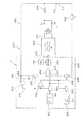
本発明を実施する場合、好適な実施形態は、溶接機200が、STT短絡溶接プロセス等の短絡アーク溶接プロセスを実施するようにプログラム可能である論理プロセッサをベースとしたコントローラCを有する、図3のブロック図および論理に示すディジタル制御スキームを用いる。インバータ202は、電流をスイッチ206およびインダクタ208を介して、被加工物214を溶接するのに用いる前進ワイヤの形の電極210へ向ける標準的な整流出力回路204を有する。電圧帰還220は、アーク電圧のレベルをディジタルコントローラCへ戻す。同様に、シャント222は、瞬時アーク電流を、フィードバックライン224によってコントローラCへ戻す。標準的な制御技術によれば、コントローラCにおける論理プロセッサは、ライン240で表わす波形制御を用いた入力ディジタル化エラー増幅器234を有する、ディジタルで実装したパルス幅変調器230を含む。パルス幅変調器230は、インバータ202にライン242のフィードバック値に基づいて、ライン240上の波形に追従させる。標準的な実施によれば、電流波形ジェネレータ250は、溶接周期の様々な部分の間、上記電極と被加工物との間に、電流パルスの所望の特性を与えるために設けられている。発振器232は、少なくとも18kHzの周波数に設定されるため、ライン233のパルスは、この高周波を有する。この発明において、電流波形ジェネレータ250は、ディジタルイネーブルスイッチ252の導通状態によって決まる溶接周期の時刻またはセグメントの部分の間にのみ、パルス変調器230によって使用される。該スイッチが使用可能になると、ジェネレータ250は、ライン224上のフィードバックレベルが、当技術分野で用いられるような標準的なSTT波形として示す所望の正確な電流特性または波形100に追従するように、ライン240上の論理を制御する。本発明によれば、電圧波形ジェネレータ260は、一定の波形150を生成するためにも設けられている。ジェネレータ260は、入力を、ディジタルイネーブルスイッチ262を介して入力240へ向ける。スイッチ252とスイッチ262は、逆に動作する。一方のイネーブルスイッチが閉じた場合、他方のイネーブルスイッチが開く。従って、エラー増幅器234は、スイッチ252、262の導通状態に従って、電流波形ジェネレータ250または電圧波形ジェネレータ260(波形150)のいずれかから生成された波形を受け取る。標準的なSTT技術によれば、dv/dt回路として示される徴候回路270は、金属移行がブレークポイント付近である場合に、スイッチ206を開く論理をライン272に生成する。そして、抵抗器274が該溶接回路に挿入されて、部分32cに沿って電流を低減する。上記電流モードと電圧モードとの間で切り替えるため、ディジタル化比較器280は、電圧フィードバック220に接続された正の入力282と、基準電圧VRによって制御される負の入力284とを有する。比較器280の出力ライン290は、電圧モードディジタルスイッチ292に接続されている。ライン290上の論理は、電流モードスイッチ298を制御するための反対の論理をライン296上に生成するために、インバータ294によって反転される。動作中、短絡のスタート時において、ライン220上の電圧が減少した場合、論理0がライン290に現れる。このことは、スイッチ292およびスイッチ262を非作動状態にする。インバータ294は、ライン296に論理1を生成する。このことは、スイッチ298を作動状態にするため、ライン224の電流フィードバックレベルは、エラー増幅器234の入力242に向けられる。同時に、ライン296上の論理1が、ディジタルスイッチ252を作動させるため、波形ジェネレータ250は、該エラー増幅器の入力240に接続される。この動作中、インバータ202は、ジェネレータ250からの波形100に追従する。上記短絡の終了時において、アーク電圧は、急速に増加する。そして、入力282上の値は、ライン284上の基準電圧を超える。電圧モードスイッチ292を閉じ、かつスイッチ262を作動させる論理1がライン290に生成されるため、ジェネレータ260は、ライン240の論理を制御する。これと同時に、スイッチ252および298が非作動状態にされる。ライン220上のフィードバック電圧信号は、スイッチ292を介して入力242へ向けられる。このようにして、インバータ202は、ジェネレータ260によって生成される一定の電圧波形150の波形に追従する。このジェネレータは、一定ワット数の波形ジェネレータまたは一定ジュールの波形ジェネレータであってもよい。これら全ての繰り返しは、短絡溶接プロセスのアーク状態を制御するために実施される。図3に開示された論理スキームは、コントローラCのディジタル技術によって処理され、様々なディジタル技術を、所望の電圧関数を一定のプラズマパラメータとして追跡する波形により該アーク状態を操作するという目的を達成するのに用いることができる。従来、アーク状態中の波形は、単に、短絡波形の伸長であったため、該アークを電圧関数として制御するという利点は利用できなかった。In practicing the present invention, a preferred embodiment includes a controller C based on a logic processor in which the
ある場合においては、溶融球が形成された後、該アーク状態中に電流制御に移行することが好ましい。ディジタルスイッチは、論理プロセッサが、図4に示すスイッチ290aによってライン290を開いた場合に用いられる。この2つの極スイッチ概念は、ライン290bをアース290cによって接地する。このことは、論理0をライン290b上に配置して、該スイッチを電流制御に移行させる。このスイッチの動作は、溶融球がプラズマパルス40によって形成された後に、上記論理プロセッサによって選択される。 In some cases, it is preferable to transition to current control during the arc condition after the molten sphere is formed. The digital switch is used when the logical processor opens the
図5および6は、図3のブロック図および論理チャートのわずかな変更例を示す。図5において、電圧関数は、一定のワット数であり、そのため、比較器280のライン282の入力は、ライン220上の電圧フィードバックと、ライン224上の電流フィードバックとの積である。これらの値は、乗算器210によって結合されて、ワット数フィードバックを表わす値をライン312に生成する。電流フィードバック224は、図3ですでに示したように、スイッチ298の入力で使用される。図5に示す、コントローラCにおけるディジタル処理のためのわずかな変更例を用いることにより、アーク状態は、ワット数フィードバックによって制御される一定のワット数波形を有し、短絡状態は、電流フィードバックにより、図3に示すように制御される。図6において、ライン312における積は、積分器320によって積分されて、ライン322にジュールフィードバックを生成する。これは、比較器280の正の入力282およびスイッチ292の入力に向けられるため、アーク状態は、所望のジュール波形150の正確な反映である一定のジュール波形によって制御される。図3に概略的に示すディジタル処理の他のこのような変形例は、アーク状態のパルス部分が、所望の電圧関数の正確な表現である波形150によって制御される限り用いることができる。CV電源の定格電圧は、溶接プロセスの異常により超えられることはない。 5 and 6 show a slight modification of the block diagram and logic chart of FIG. In FIG. 5, the voltage function is a constant wattage, so the input on
次に、図7〜9について説明すると、溶接機200の変更例が示されている。変更された溶接機200’は、ダーリントンスイッチ206およびネック徴候回路270が取り除かれた変更STT溶接機である。この変更回路は、それぞれ図1および2に示す波形の対応部分と同じ符号を有する、図7に示すような波形を生成する。該ダーリントンスイッチを取り除くことにより、インダクタ208は、ブレッドポイント32cから定電圧波形40への電流の低下を制御して、急速な時間一定曲線400に沿って移行させる。これは、変更STT曲線である。この変更例の場合、短絡状態30における移行は、時間一定曲線402に沿ったものである。同様に、図8に示す波形は、移行曲線410および導入移行曲線412を有する。本発明の好適な実施形態のこれらのわずかな変更例は、オハイオ州クリーブランドのLincoln Electric Companyによって普及した同じSTT溶接プロセスを必ず用いることなく、本発明の効果を可能にする。電流波形と、一定のパラメータ波形による波形のプラズマまたはアーク状態とにより該溶接プロセスの短絡状態を制御する図9の変形例以外の溶接機のその他の変更例は、本発明の実施を可能にする。 Next, with reference to FIGS. 7 to 9, a modified example of the
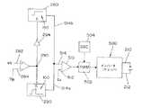
インバータ500または同等のチョッパーが、発振器504により18kHzを超える周波数で作動するパルス幅変調器502によって制御される波形を有する、本発明の実施の単純化した図を図10に示す。エラー増幅器510は、アーク電流検知装置からの帰還入力512と、ライン514aにより波形ジェネレータ250に接続され、かつライン514bにより波形ジェネレータ260に接続された制御入力514とを有する。ライン282上のアーク電圧は、パルス幅変調器502へ伝送される波形の特性を決める。標準的な実施によれば、上記徴候回路は、プラズマ状態への移行を無効にする。そして、先立ってアーク状態を発生させる。ライン282上の論理は、インバータ500によって処理される特定の波形100または150を制御する。この一般的なシステムは、図1、2および7、8に示す溶接プロセスを実行する場合に用いられる。 A simplified diagram of an implementation of the present invention is shown in FIG. 10 where the
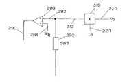
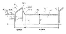
2つの傾斜構成波形100が詳細に示されている本発明の別の態様を図11および12に示す。この波形は、波形100が電流制御であり、かつ波形150が異なって、例えば、電圧によって制御される溶接機において使用される。該溶接プロセスの各波形に対して2つの別々の制御モードを用いた場合、電流波形が、図3および9のジェネレータ250の制御を構成する回路520によって得られるような形状を有することを保障することが有利である。回路520は、スイッチ526が開いてアークがないことが示されたときに、コンデンサ524の放電によって制御される積分増幅器522を含む。これは、波形100の間である。コンデンサ524は、図12に示すような波形100の第1の部分550の間に、アース532に対して抵抗器530を介して放電される。積分器522は、入力基準540と制御入力542とを有する。該積分器は、コンデンサ524が放電したときに、第1の部分550が、概して直線であることを保障する。出力544が、バッテリー549により作動される加減抵抗器548による手動調節によって入力546上の電圧により設定されるブレークポイント電流32bに達すると、比較器560は、スイッチ564を閉じる信号をライン562に生成する。このことは、抵抗器566を抵抗器530と並列にして、コンデンサ524の放電速度を増加させる。従って、ブレークポイント32bの後、部分552の傾斜は、図12に示すように減少する。電流波形100は、ライン272のネック信号により、あるいは、通常550アンペアの設定値に達するライン544上の電流によって終了する。このことは、図示しない標準的な最大電流回路によってなされる。2つの傾斜電流パルスを用いることにより、一定の電圧パルス波形150の使用は、上記アーク溶接機の短絡制御に影響を及ぼさない。Another aspect of the present invention in which two sloped
本発明の1つの態様によれば、波形技術を用いた電気アーク溶接機は、図13に概略的に示すような電流ブレークポイント調整回路600を有する。標準的な手動調節要素548は、ブレークポイントレベル信号を、ライン612によって回路610に入力する加減抵抗器602を用いる。従って、設定ポイント32bは、手動で調整される。本発明は、ライン632上の信号によって、アーク溶接機コントローラ630のパラメータを調整する、手動調節可能なパラメータ回路620の使用を含む。該パラメータ回路は、好ましくは、ノブ652によって調節される電圧回路650である。スイッチ660は、ライン632または666の信号を入力612に接続するために、端子662、664間で移動可能である。このことは、短絡電流波形のブレークポイントを設定する。他のパラメータも、ワイヤ送給速度等の設定ポイントを調整するのに用いることができる。
電気アーク溶接機を構成するために、必要に応じて、様々な構成要素を組み合わせることができる。According to one aspect of the present invention, an electric arc welder using waveform technology has a current
Various components can be combined as needed to construct an electric arc welder.
10 短絡状態
12 アーク状態
32b ブレークポイント
32c 徴候ポイント
40 プラズマパルス10
Claims (9)
Translated fromJapanese前記プロセスが、前記短絡状態中の第1の電流制御波形と、アーク状態中の第2の電圧制御波形とを有する短絡状態とアーク状態との連続的な入れ代わりからなり、
18kHz以上のレートで作動するパルス波変調器によって制御される一連の電流パルスから前記第1の波形を構成する第1の波形ジェネレータと、
18kHz以上のレートで作動するパルス波変調器によって制御される一連の電流パルスから前記第2の波形を構成する第2の波形ジェネレータとを備える電気アーク溶接機において、
前記第1の波形が、第1の傾斜と、ブレークポイントと、第2の傾斜とを有し、
前記ブレークポイントの電流レベルを手動調整するブレークポイント回路を含むことを特徴とする電気アーク溶接機。An electric arc welder that operates to perform a short circuit welding process between an electrode and a workpiece,
The process comprises a continuous replacement of a short circuit condition and an arc condition having a first current control waveform during the short circuit condition and a second voltage control waveform during the arc condition;
A first waveform generator constituting the first waveform from a series of current pulses controlled by a pulse wave modulator operating at a rate of 18 kHz or higher;
An electric arc welder comprising: a second waveform generator that constitutes the second waveform from a series of current pulses controlled by a pulse wave modulator operating at a rate of 18 kHz or higher;
The first waveform has a first slope, a breakpoint, and a second slope;
An electric arc welder comprising a breakpoint circuit for manually adjusting a current level of the breakpoint.
前記検知した電圧が所定値よりも大きい場合に、前記電圧検出器からのアーク信号の生成時に、前記短絡状態から前記アーク状態に前記溶接プロセスを移行させる回路とを有することを特徴とする請求項1又は2に記載の電気アーク溶接機。A voltage detector comprising a circuit for detecting an arc voltage between the electrode and the workpiece;
A circuit for transferring the welding process from the short-circuit state to the arc state when generating an arc signal from the voltage detector when the detected voltage is larger than a predetermined value. The electric arc welder according to 1or 2 .
前記アークスイッチと並列に設けた抵抗器と、
前記アーク信号の生成時に、前記アークスイッチを開くための回路とを含むことを特徴とする請求項3記載の電気アーク溶接機。The welding machine includes an arc switch provided in series with the electrode and the workpiece;
A resistor provided in parallel with the arc switch;
4. An electric arc welder according to claim3 , further comprising a circuit for opening the arc switch when the arc signal is generated.
前記プロセスが、短絡状態とアーク状態との連続的な入れ代わりであるプロセスであり、前記プロセスが、前記短絡状態中の第1の電流制御波形を具備し、
前記電気アーク溶接機が、
18kHz以上のレートで作動するパルス波変調器によって制御される一連の電流パルスから前記第1の電流制御波形を形成する第1の波形ジェネレータを具備し、
前記第1の電流制御波形が、第1の傾斜と、ブレークポイントと、第2の傾斜とを含み、更に、
入力信号に応じて前記ブレークポイントの電流を設定するブレークポイント回路と、
前記ブレークポイント回路に対する第1の手動調節可能な入力信号と、
前記ブレークポイント回路に対する第2の手動調節可能な入力信号と、
前記入力信号のうちの1つを前記ブレークポイント回路に接続するスイッチと、
で構成したことを特徴とする電気アーク溶接機。An electric arc welder that operates to perform a short circuit welding process between an electrode and a workpiece,
The process is a continuous replacement of a short circuit condition and an arc condition, the process comprising a first current control waveform during the short circuit condition;
The electric arc welder is
Comprising a first waveform generator that forms the first current control waveform from a series of current pulses controlled by a pulse wave modulator operating at a rate of 18 kHz or higher;
The first current control waveform includes a first slope, a breakpoint, and a second slope;
A breakpoint circuit for setting the current of the breakpoint according to an input signal;
A first manually adjustable input signal to the breakpoint circuit;
A second manually adjustable input signal to the breakpoint circuit;
A switch connecting one of the input signals to the breakpoint circuit;
An electric arc welding machine characterized by comprising.
Applications Claiming Priority (1)
| Application Number | Priority Date | Filing Date | Title |
|---|---|---|---|
| US10/783,115US7109439B2 (en) | 2004-02-23 | 2004-02-23 | Short circuit arc welder and method of controlling same |
Publications (2)
| Publication Number | Publication Date |
|---|---|
| JP2005238329A JP2005238329A (en) | 2005-09-08 |
| JP4291257B2true JP4291257B2 (en) | 2009-07-08 |
Family
ID=34750455
Family Applications (1)
| Application Number | Title | Priority Date | Filing Date |
|---|---|---|---|
| JP2004370874AExpired - LifetimeJP4291257B2 (en) | 2004-02-23 | 2004-12-22 | Short-circuit arc welder and control method thereof |
Country Status (9)
| Country | Link |
|---|---|
| US (1) | US7109439B2 (en) |
| EP (1) | EP1570937B1 (en) |
| JP (1) | JP4291257B2 (en) |
| KR (1) | KR100607980B1 (en) |
| AU (1) | AU2004212533B2 (en) |
| BR (1) | BRPI0404323A (en) |
| CA (1) | CA2479694C (en) |
| ES (1) | ES2393309T3 (en) |
| MX (1) | MXPA04011695A (en) |
Families Citing this family (62)
| Publication number | Priority date | Publication date | Assignee | Title |
|---|---|---|---|---|
| US8203099B2 (en)* | 2004-06-04 | 2012-06-19 | Lincoln Global, Inc. | Method and device to build-up, clad, or hard-face with minimal admixture |
| US8704131B2 (en)* | 2006-03-31 | 2014-04-22 | Illinois Tool Works Inc. | Method and apparatus for pulse welding |
| DE102007004177A1 (en)* | 2007-01-27 | 2008-08-07 | Ewm Hightec Welding Gmbh | Gentle short-circuit entry |
| US20090261073A1 (en)* | 2008-04-22 | 2009-10-22 | Lincoln Global, Inc. | System and methods of using variable waveform ac arc welding to achieve specific weld metal chemistries |
| GB0819377D0 (en)* | 2008-10-22 | 2008-11-26 | Saipem Spa | Method and apparatus for measuring a pipe weld joint |
| US9085041B2 (en) | 2009-01-13 | 2015-07-21 | Lincoln Global, Inc. | Method and system to start and use combination filler wire feed and high intensity energy source for welding |
| US10086461B2 (en) | 2009-01-13 | 2018-10-02 | Lincoln Global, Inc. | Method and system to start and use combination filler wire feed and high intensity energy source for welding |
| US8653417B2 (en)* | 2009-01-13 | 2014-02-18 | Lincoln Global, Inc. | Method and system to start and use a combination filler wire feed and high intensity energy source |
| WO2010116695A1 (en) | 2009-04-08 | 2010-10-14 | パナソニック株式会社 | Arc welding method and arc welding device |
| US8809736B2 (en)* | 2009-07-29 | 2014-08-19 | Panasonic Corporation | Arc welding method and arc welding apparatus |
| KR101642547B1 (en)* | 2010-05-28 | 2016-07-25 | 이에스에이비 아베 | Short arc welding system |
| US9403231B2 (en)* | 2011-11-09 | 2016-08-02 | Illinois Tool Works Inc. | Hybrid pulsed-short circuit welding regime |
| US9403233B2 (en) | 2011-12-16 | 2016-08-02 | Illinois Tool Works Inc. | DC electrode negative rotating arc welding method and system |
| CN104640664B (en) | 2012-07-12 | 2017-05-03 | 林肯环球股份有限公司 | Method of and system for starting and useing in combination a filler wire feed and arc generating source for welding |
| US9511442B2 (en) | 2012-07-27 | 2016-12-06 | Illinois Tool Works Inc. | Adaptable rotating arc welding method and system |
| DE212013000247U1 (en) | 2012-12-06 | 2015-10-09 | Lincoln Global, Inc. | System for starting and using a combined cored wire feed and high intensity power source for welding |
| US10040143B2 (en) | 2012-12-12 | 2018-08-07 | Illinois Tool Works Inc. | Dabbing pulsed welding system and method |
| US10906114B2 (en) | 2012-12-21 | 2021-02-02 | Illinois Tool Works Inc. | System for arc welding with enhanced metal deposition |
| US9950383B2 (en) | 2013-02-05 | 2018-04-24 | Illinois Tool Works Inc. | Welding wire preheating system and method |
| US10835983B2 (en) | 2013-03-14 | 2020-11-17 | Illinois Tool Works Inc. | Electrode negative pulse welding system and method |
| US11045891B2 (en) | 2013-06-13 | 2021-06-29 | Illinois Tool Works Inc. | Systems and methods for anomalous cathode event control |
| US9498838B2 (en) | 2013-07-24 | 2016-11-22 | Lincoln Global, Inc. | System and method of controlling heat input in tandem hot-wire applications |
| WO2015022569A2 (en) | 2013-08-13 | 2015-02-19 | Lincoln Global, Inc. | Method and system to start and use combination filler wire feed and high intensity energy source for welding aluminium to steel |
| US10953484B2 (en) | 2013-09-16 | 2021-03-23 | Illinois Tool Works Inc. | Narrow groove welding method and system |
| US10543551B2 (en) | 2013-09-16 | 2020-01-28 | Illinois Tool Works Inc. | Synchronized rotating arc welding method and system |
| US10828728B2 (en) | 2013-09-26 | 2020-11-10 | Illinois Tool Works Inc. | Hotwire deposition material processing system and method |
| US10464168B2 (en) | 2014-01-24 | 2019-11-05 | Lincoln Global, Inc. | Method and system for additive manufacturing using high energy source and hot-wire |
| WO2015124977A1 (en) | 2014-02-21 | 2015-08-27 | Lincoln Global, Inc. | Hybrid hot-wire and arc welding method and system using offset positioning |
| US9718147B2 (en) | 2014-03-07 | 2017-08-01 | Lincoln Global, Inc. | Method and system to start and use combination filler wire feed and high intensity energy source for root pass welding of the inner diameter of clad pipe |
| US10052706B2 (en) | 2014-04-04 | 2018-08-21 | Lincoln Global, Inc. | Method and system to use AC welding waveform and enhanced consumable to improve welding of galvanized workpiece |
| CN103962686B (en)* | 2014-04-25 | 2015-12-09 | 深圳麦格米特电气股份有限公司 | Consumable electrode arc welding molten drop necking down detection method |
| US11154946B2 (en) | 2014-06-30 | 2021-10-26 | Illinois Tool Works Inc. | Systems and methods for the control of welding parameters |
| US11198189B2 (en) | 2014-09-17 | 2021-12-14 | Illinois Tool Works Inc. | Electrode negative pulse welding system and method |
| US11478870B2 (en) | 2014-11-26 | 2022-10-25 | Illinois Tool Works Inc. | Dabbing pulsed welding system and method |
| US10189106B2 (en) | 2014-12-11 | 2019-01-29 | Illinois Tool Works Inc. | Reduced energy welding system and method |
| US11370050B2 (en) | 2015-03-31 | 2022-06-28 | Illinois Tool Works Inc. | Controlled short circuit welding system and method |
| CN104972197B (en)* | 2015-07-20 | 2017-04-26 | 中北大学 | Welding process quality evaluation method for shielded metal arc welding |
| US11285559B2 (en) | 2015-11-30 | 2022-03-29 | Illinois Tool Works Inc. | Welding system and method for shielded welding wires |
| US10610946B2 (en) | 2015-12-07 | 2020-04-07 | Illinois Tool Works, Inc. | Systems and methods for automated root pass welding |
| US10675699B2 (en) | 2015-12-10 | 2020-06-09 | Illinois Tool Works Inc. | Systems, methods, and apparatus to preheat welding wire |
| US12194579B2 (en) | 2015-12-10 | 2025-01-14 | Illinois Tool Works Inc. | Systems, methods, and apparatus to preheat welding wire |
| GB2560995A (en)* | 2017-03-31 | 2018-10-03 | Macgregor Welding Systems Ltd | Welding apparatus and method |
| US10766092B2 (en) | 2017-04-18 | 2020-09-08 | Illinois Tool Works Inc. | Systems, methods, and apparatus to provide preheat voltage feedback loss protection |
| US10870164B2 (en) | 2017-05-16 | 2020-12-22 | Illinois Tool Works Inc. | Systems, methods, and apparatus to preheat welding wire |
| EP4151349A1 (en) | 2017-06-09 | 2023-03-22 | Illinois Tool Works, Inc. | Welding torch with two contact tips and same tool center point as torch with one contact tip |
| CA3066666A1 (en) | 2017-06-09 | 2018-12-13 | Illinois Tool Works Inc. | Contact tips with screw threads and head to enable unthreading of the screw threads comprising longitudinal slots for gas flow; welding torch with contact tips |
| US11590597B2 (en) | 2017-06-09 | 2023-02-28 | Illinois Tool Works Inc. | Systems, methods, and apparatus to preheat welding wire |
| US11524354B2 (en) | 2017-06-09 | 2022-12-13 | Illinois Tool Works Inc. | Systems, methods, and apparatus to control weld current in a preheating system |
| CA3066687C (en) | 2017-06-09 | 2022-08-02 | Illinois Tool Works Inc. | Welding torch, with two contact tips and a plurality of liquid cooling assemblies for conducting currents to the contact tips |
| US11020813B2 (en) | 2017-09-13 | 2021-06-01 | Illinois Tool Works Inc. | Systems, methods, and apparatus to reduce cast in a welding wire |
| US11027362B2 (en) | 2017-12-19 | 2021-06-08 | Lincoln Global, Inc. | Systems and methods providing location feedback for additive manufacturing |
| US11654503B2 (en) | 2018-08-31 | 2023-05-23 | Illinois Tool Works Inc. | Submerged arc welding systems and submerged arc welding torches to resistively preheat electrode wire |
| US11014185B2 (en) | 2018-09-27 | 2021-05-25 | Illinois Tool Works Inc. | Systems, methods, and apparatus for control of wire preheating in welding-type systems |
| US12115604B2 (en)* | 2018-10-19 | 2024-10-15 | Illinois Tool Works Inc. | Systems and methods for voltage control of a short circuit during a pulse welding process |
| CN113474113A (en) | 2018-12-19 | 2021-10-01 | 伊利诺斯工具制品有限公司 | Contact tip, wire preheating assembly, contact tip assembly and consumable electrode feed welding-type system |
| US20200238418A1 (en)* | 2019-01-24 | 2020-07-30 | Illinois Tool Works Inc. | Systems and methods with integrated switch for controlled short circuit welding processes |
| US20200246902A1 (en)* | 2019-01-31 | 2020-08-06 | Illinois Tool Works Inc. | Systems and methods for controlled arc and short phase time adjustment |
| US11623292B2 (en)* | 2019-03-29 | 2023-04-11 | Lincoln Global, Inc. | Real time resistance monitoring of an arc welding circuit |
| US12103121B2 (en) | 2019-04-30 | 2024-10-01 | Illinois Tool Works Inc. | Methods and apparatus to control welding power and preheating power |
| EP3772389A1 (en)* | 2019-08-06 | 2021-02-10 | Fronius International GmbH | Method and device for stabilizing a transition between different welding process phases of a welding process |
| US11772182B2 (en) | 2019-12-20 | 2023-10-03 | Illinois Tool Works Inc. | Systems and methods for gas control during welding wire pretreatments |
| US12194574B2 (en) | 2021-09-02 | 2025-01-14 | Lincoln Global, Inc. | System and method for adapting break point for short circuit welding |
Family Cites Families (16)
| Publication number | Priority date | Publication date | Assignee | Title |
|---|---|---|---|---|
| JPS57168773A (en)* | 1981-04-10 | 1982-10-18 | Mitsubishi Electric Corp | Short circuit transfer arc welding machine |
| US4546234A (en)* | 1983-08-11 | 1985-10-08 | Kabushiki Kaisha Kobe Seiko Sho | Output control of short circuit welding power source |
| JPS60145277A (en)* | 1984-01-06 | 1985-07-31 | Kobe Steel Ltd | Method for controlling output of welding power source |
| US4954691A (en)* | 1986-12-10 | 1990-09-04 | The Lincoln Electric Company | Method and device for controlling a short circuiting type welding system |
| US5003154A (en)* | 1986-12-11 | 1991-03-26 | The Lincoln Electric Company | Apparatus and method of short circuiting arc welding |
| US4866247A (en) | 1986-12-11 | 1989-09-12 | The Lincoln Electric Company | Apparatus and method of short circuiting arc welding |
| US5148001A (en) | 1986-12-11 | 1992-09-15 | The Lincoln Electric Company | System and method of short circuiting arc welding |
| US5001326A (en)* | 1986-12-11 | 1991-03-19 | The Lincoln Electric Company | Apparatus and method of controlling a welding cycle |
| US4717807A (en) | 1986-12-11 | 1988-01-05 | The Lincoln Electric Company | Method and device for controlling a short circuiting type welding system |
| AU596761B2 (en)* | 1987-12-21 | 1990-05-10 | Lincoln Electric Company, The | Apparatus and method of short circuiting arc welding |
| US5278390A (en) | 1993-03-18 | 1994-01-11 | The Lincoln Electric Company | System and method for controlling a welding process for an arc welder |
| US5961863A (en)* | 1998-01-09 | 1999-10-05 | Lincoln Global, Inc. | Short circuit pipe welding |
| US6051810A (en) | 1998-01-09 | 2000-04-18 | Lincoln Global, Inc. | Short circuit welder |
| US6087626A (en)* | 1998-02-17 | 2000-07-11 | Illinois Tool Works Inc. | Method and apparatus for welding |
| US6015964A (en) | 1998-08-03 | 2000-01-18 | Lincoln Global, Inc. | Electric arc welder with controlled arc |
| US6501049B2 (en) | 2001-01-23 | 2002-12-31 | Lincoln Global, Inc. | Short circuit arc welder and method of controlling same |
- 2004
- 2004-02-23USUS10/783,115patent/US7109439B2/ennot_activeExpired - Lifetime
- 2004-08-31CACA002479694Apatent/CA2479694C/ennot_activeExpired - Fee Related
- 2004-09-15AUAU2004212533Apatent/AU2004212533B2/ennot_activeCeased
- 2004-09-21KRKR1020040075336Apatent/KR100607980B1/ennot_activeExpired - Fee Related
- 2004-09-30ESES04023284Tpatent/ES2393309T3/ennot_activeExpired - Lifetime
- 2004-09-30EPEP04023284Apatent/EP1570937B1/ennot_activeExpired - Lifetime
- 2004-10-05BRBR0404323-5Apatent/BRPI0404323A/ennot_activeIP Right Cessation
- 2004-11-25MXMXPA04011695Apatent/MXPA04011695A/enactiveIP Right Grant
- 2004-12-22JPJP2004370874Apatent/JP4291257B2/ennot_activeExpired - Lifetime
Also Published As
| Publication number | Publication date |
|---|---|
| AU2004212533A1 (en) | 2005-09-08 |
| MXPA04011695A (en) | 2005-10-26 |
| CA2479694A1 (en) | 2005-08-23 |
| EP1570937B1 (en) | 2012-08-08 |
| AU2004212533B2 (en) | 2007-01-18 |
| BRPI0404323A (en) | 2005-11-01 |
| JP2005238329A (en) | 2005-09-08 |
| US20050184039A1 (en) | 2005-08-25 |
| ES2393309T3 (en) | 2012-12-20 |
| US7109439B2 (en) | 2006-09-19 |
| KR20050083537A (en) | 2005-08-26 |
| CA2479694C (en) | 2008-04-29 |
| EP1570937A2 (en) | 2005-09-07 |
| EP1570937A3 (en) | 2008-01-02 |
| KR100607980B1 (en) | 2006-08-09 |
Similar Documents
| Publication | Publication Date | Title |
|---|---|---|
| JP4291257B2 (en) | Short-circuit arc welder and control method thereof | |
| KR100493125B1 (en) | Short circuit arc welder and method of controlling same | |
| CA2260118C (en) | Method and apparatus for short arc welding | |
| US6995338B2 (en) | Method and apparatus for short circuit welding | |
| US6933466B2 (en) | Method and apparatus for arc welding with wire heat control | |
| US7842903B2 (en) | Short arc welding system | |
| KR20140144730A (en) | Improved process for surface tension transfer short circuit welding | |
| JP6945290B2 (en) | Welding system for AC welding with reduced spatter | |
| AU772634B2 (en) | A welding control system |
Legal Events
| Date | Code | Title | Description |
|---|---|---|---|
| A131 | Notification of reasons for refusal | Free format text:JAPANESE INTERMEDIATE CODE: A131 Effective date:20080325 | |
| A521 | Written amendment | Free format text:JAPANESE INTERMEDIATE CODE: A523 Effective date:20080625 | |
| A131 | Notification of reasons for refusal | Free format text:JAPANESE INTERMEDIATE CODE: A131 Effective date:20080924 | |
| A521 | Written amendment | Free format text:JAPANESE INTERMEDIATE CODE: A523 Effective date:20081219 | |
| TRDD | Decision of grant or rejection written | ||
| A01 | Written decision to grant a patent or to grant a registration (utility model) | Free format text:JAPANESE INTERMEDIATE CODE: A01 Effective date:20090324 | |
| A01 | Written decision to grant a patent or to grant a registration (utility model) | Free format text:JAPANESE INTERMEDIATE CODE: A01 | |
| A61 | First payment of annual fees (during grant procedure) | Free format text:JAPANESE INTERMEDIATE CODE: A61 Effective date:20090402 | |
| R150 | Certificate of patent or registration of utility model | Free format text:JAPANESE INTERMEDIATE CODE: R150 | |
| FPAY | Renewal fee payment (event date is renewal date of database) | Free format text:PAYMENT UNTIL: 20120410 Year of fee payment:3 | |
| FPAY | Renewal fee payment (event date is renewal date of database) | Free format text:PAYMENT UNTIL: 20120410 Year of fee payment:3 | |
| FPAY | Renewal fee payment (event date is renewal date of database) | Free format text:PAYMENT UNTIL: 20130410 Year of fee payment:4 | |
| FPAY | Renewal fee payment (event date is renewal date of database) | Free format text:PAYMENT UNTIL: 20130410 Year of fee payment:4 | |
| FPAY | Renewal fee payment (event date is renewal date of database) | Free format text:PAYMENT UNTIL: 20140410 Year of fee payment:5 | |
| R250 | Receipt of annual fees | Free format text:JAPANESE INTERMEDIATE CODE: R250 | |
| R250 | Receipt of annual fees | Free format text:JAPANESE INTERMEDIATE CODE: R250 | |
| R250 | Receipt of annual fees | Free format text:JAPANESE INTERMEDIATE CODE: R250 | |
| R250 | Receipt of annual fees | Free format text:JAPANESE INTERMEDIATE CODE: R250 | |
| R250 | Receipt of annual fees | Free format text:JAPANESE INTERMEDIATE CODE: R250 | |
| R250 | Receipt of annual fees | Free format text:JAPANESE INTERMEDIATE CODE: R250 |