JP4291202B2 - Ultrasonic treatment device - Google Patents
Ultrasonic treatment deviceDownload PDFInfo
- Publication number
- JP4291202B2 JP4291202B2JP2004124184AJP2004124184AJP4291202B2JP 4291202 B2JP4291202 B2JP 4291202B2JP 2004124184 AJP2004124184 AJP 2004124184AJP 2004124184 AJP2004124184 AJP 2004124184AJP 4291202 B2JP4291202 B2JP 4291202B2
- Authority
- JP
- Japan
- Prior art keywords
- ultrasonic
- treatment
- vibration
- flexible probe
- ultrasonic treatment
- Prior art date
- Legal status (The legal status is an assumption and is not a legal conclusion. Google has not performed a legal analysis and makes no representation as to the accuracy of the status listed.)
- Expired - Lifetime
Links
- 238000009210therapy by ultrasoundMethods0.000titleclaimsdescription44
- 230000005540biological transmissionEffects0.000claimsdescription15
- 238000002955isolationMethods0.000claims1
- 239000000523sampleSubstances0.000description43
- 230000007704transitionEffects0.000description4
- 238000003780insertionMethods0.000description3
- 230000037431insertionEffects0.000description3
- 238000000034methodMethods0.000description3
- 238000012986modificationMethods0.000description3
- 230000004048modificationEffects0.000description3
- 230000005489elastic deformationEffects0.000description2
- 229910000737DuraluminInorganic materials0.000description1
- 229910000990Ni alloyInorganic materials0.000description1
- 239000004642PolyimideSubstances0.000description1
- 238000005452bendingMethods0.000description1
- 230000000694effectsEffects0.000description1
- 239000000835fiberSubstances0.000description1
- 230000002452interceptive effectEffects0.000description1
- 229910052751metalInorganic materials0.000description1
- 239000002184metalSubstances0.000description1
- 150000002739metalsChemical class0.000description1
- 229920001721polyimidePolymers0.000description1
- 239000010453quartzSubstances0.000description1
- VYPSYNLAJGMNEJ-UHFFFAOYSA-Nsilicon dioxideInorganic materialsO=[Si]=OVYPSYNLAJGMNEJ-UHFFFAOYSA-N0.000description1
- 239000010935stainless steelSubstances0.000description1
- 229910001220stainless steelInorganic materials0.000description1
Images


Classifications
- A—HUMAN NECESSITIES
- A61—MEDICAL OR VETERINARY SCIENCE; HYGIENE
- A61B—DIAGNOSIS; SURGERY; IDENTIFICATION
- A61B17/00—Surgical instruments, devices or methods
- A61B17/32—Surgical cutting instruments
- A61B17/320068—Surgical cutting instruments using mechanical vibrations, e.g. ultrasonic
- A61B17/320092—Surgical cutting instruments using mechanical vibrations, e.g. ultrasonic with additional movable means for clamping or cutting tissue, e.g. with a pivoting jaw
- A—HUMAN NECESSITIES
- A61—MEDICAL OR VETERINARY SCIENCE; HYGIENE
- A61B—DIAGNOSIS; SURGERY; IDENTIFICATION
- A61B17/00—Surgical instruments, devices or methods
- A61B17/28—Surgical forceps
- A61B17/29—Forceps for use in minimally invasive surgery
- A61B2017/2901—Details of shaft
- A61B2017/2902—Details of shaft characterized by features of the actuating rod
- A—HUMAN NECESSITIES
- A61—MEDICAL OR VETERINARY SCIENCE; HYGIENE
- A61B—DIAGNOSIS; SURGERY; IDENTIFICATION
- A61B17/00—Surgical instruments, devices or methods
- A61B17/32—Surgical cutting instruments
- A61B17/320068—Surgical cutting instruments using mechanical vibrations, e.g. ultrasonic
- A61B2017/320088—Surgical cutting instruments using mechanical vibrations, e.g. ultrasonic with acoustic insulation, e.g. elements for damping vibrations between horn and surrounding sheath
Landscapes
- Health & Medical Sciences (AREA)
- Surgery (AREA)
- Engineering & Computer Science (AREA)
- Life Sciences & Earth Sciences (AREA)
- Heart & Thoracic Surgery (AREA)
- Nuclear Medicine, Radiotherapy & Molecular Imaging (AREA)
- Mechanical Engineering (AREA)
- Biomedical Technology (AREA)
- Dentistry (AREA)
- Medical Informatics (AREA)
- Molecular Biology (AREA)
- Animal Behavior & Ethology (AREA)
- General Health & Medical Sciences (AREA)
- Public Health (AREA)
- Veterinary Medicine (AREA)
- Surgical Instruments (AREA)
Description
Translated fromJapanese本発明は、超音波処置具に関するものである。 The present invention relates to an ultrasonic treatment instrument.
従来、超音波振動を利用して生体組織を凝固させ、切開(切除)する超音波処置具が知られている。このような超音波処置具は、例えば、超音波振動を伝達するプローブ先端の処置部がループ状或いは棒状に成形され、このループ状或いは棒状の処置部によって生体組織に超音波処置を施していた(例えば、特許文献1,2参照)。 2. Description of the Related Art Conventionally, an ultrasonic treatment tool that coagulates and cuts (removes) a living tissue using ultrasonic vibration is known. In such an ultrasonic treatment instrument, for example, a treatment portion at the tip of a probe that transmits ultrasonic vibration is formed in a loop shape or a rod shape, and ultrasonic treatment is performed on a living tissue by the loop shape or the rod shape treatment portion. (For example, refer to
ところで、体腔内へ挿入される挿入部が湾曲自在に構成されたいわゆる軟性内視鏡においては、挿入部の湾曲に対応して自在に曲がる可撓性プローブを用いた超音波処置具が使用されている。ここで、可撓性プローブとは、例えば、90°以上曲げたときに、弾性変形によって略元の形に戻る特性を有するプローブを言う。このような可撓性プローブを用いた従来の超音波処置具は、プローブ先端に鉗子を設けたものがないことから、生体組織を挟んで超音波処置を施すことができず、このような機能を有した超音波処置具の提供が望まれていた。 By the way, in a so-called flexible endoscope in which an insertion portion to be inserted into a body cavity is configured to be bendable, an ultrasonic treatment tool using a flexible probe that bends freely corresponding to the bending of the insertion portion is used. ing. Here, the flexible probe means, for example, a probe having a characteristic of returning to a substantially original shape by elastic deformation when bent by 90 ° or more. Since there is no conventional ultrasonic treatment instrument using such a flexible probe with forceps at the tip of the probe, ultrasonic treatment cannot be performed with a living tissue sandwiched between them. It has been desired to provide an ultrasonic treatment device having
本発明は、上記に鑑みてなされたものであって、生体組織を挟んで超音波処置を施すことができる可撓性プローブを用いた超音波処置具を提供することを目的とする。 This invention is made | formed in view of the above, Comprising: It aims at providing the ultrasonic treatment tool using the flexible probe which can perform an ultrasonic treatment on both sides of a biological tissue.
上述した課題を解決し、目的を達成するために、請求項1に係る超音波処置具は、可撓性を有する伝達部材の先端へ超音波発生手段が発生した超音波を伝達し、超音波処置を施す超音波処置具であって、前記伝達部材の先端に処置部を設けると共に、前記処置部と係合して生体組織を把持し、操作ワイヤによって開閉される把持部材を前記処置部に設け、前記処置部は、前記超音波の波長の略1/2の長さを有し、先端が前記超音波の振動における腹となり、前記超音波の伝達方向に直交する面における断面積を前記伝達部材よりも大きくして剛性が付与され、前記把持部材は、前記超音波の振動における節位置において前記処置部と係合され、前記操作ワイヤは、一端が前記把持部材に連結され、他端が操作部材に連結されて前記操作部材によって操作されることを特徴とする。 In order to solve the above-described problems and achieve the object, the ultrasonic treatment device according to claim 1 transmits ultrasonic waves generated by the ultrasonic wave generation means to the distal end of a flexible transmission member. An ultrasonic treatment instrument for performing a treatment, wherein a treatment portion is provided at a distal end of the transmission member, and a grasping member that engages with the treatment portion to grasp a living tissue and is opened and closed by an operation wire is attached to the treatment portion. The treatment portion has a length approximately half of the wavelength of the ultrasonic wave, the tip is an antinode in the vibration of the ultrasonic wave, and a cross-sectional area on a plane orthogonal to the transmission direction of the ultrasonic wave is It is larger than the transmission member and is given rigidity, and the gripping member is engaged with the treatment portion at a node position in the ultrasonic vibration, and one end of the operation wire is connected to the gripping member and the other end Is connected to the operating member and the operating member Accordingly, characterized in that it is operated.
請求項1の超音波処置具によれば、鉗子と剛性が付与された処置部とによって生体組織を挟み、可撓性の伝達部材を伝達されてくる超音波によって生体組織に超音波処置が施される。 According to the ultrasonic treatment instrument of the first aspect, the biological tissue is sandwiched between the forceps and the treatment portion provided with rigidity, and ultrasonic treatment is performed on the biological tissue by the ultrasonic wave transmitted through the flexible transmission member. Is done.
また、請求項2に係る超音波処置具は、上記の発明において、前記伝達部材は、シースによって覆われていることを特徴とする。 The ultrasonic treatment instrument according to
また、請求項3に係る超音波処置具は、上記の発明において、前記伝達部材は、前記超音波の振動における節位置に、前記シース内面と当接する防振部材が設けられていることを特徴とする。 The ultrasonic treatment instrument according to
本発明にかかる超音波処置具は、処置部に剛性が付与されているので、把持部材と処置部とによって生体組織を挟んで超音波処置を施すことができるという効果を奏する。 The ultrasonic treatment instrument according to the present invention has an effect that ultrasonic treatment can be performed with the living tissue sandwiched between the grasping member and the treatment portion because the treatment portion is provided with rigidity.
以下に、本発明にかかる超音波処置具の実施の形態を、図面を参照して詳細に説明する。図1は、本発明にかかる超音波処置具の概略構成を一部破断して示す断面図である。図2は、図1の超音波処置具先端の処置部,鉗子及び操作ワイヤを示す斜視図である。図3は、図2を部分的に断面にして示した底面図である。 Hereinafter, embodiments of an ultrasonic treatment device according to the present invention will be described in detail with reference to the drawings. FIG. 1 is a cross-sectional view illustrating a schematic configuration of an ultrasonic treatment device according to the present invention, partially broken away. FIG. 2 is a perspective view showing a treatment portion, forceps, and an operation wire at the distal end of the ultrasonic treatment instrument of FIG. FIG. 3 is a bottom view showing FIG. 2 partially in cross section.
超音波処置具1は、図1に示すように、超音波振動子ユニット2、長尺の可撓性プローブ3、鉗子5及び操作ユニット9を備えている。 As shown in FIG. 1, the
超音波振動子ユニット2は、図1に示すように、ホーン2aを有するボルト締めランジュバン型の振動子であり、支持部材8に取り付けられ、電源ケーブル2bによって電源と接続されている。超音波振動子ユニット2は、ホーン2aのフランジ部2cを固定することで、超音波振動子2d及びホーン2aの部分がケーシング2eに収納固定されている。このとき、電源ケーブル2bと前記電源との間にはフットスイッチが設けられ、超音波処置具1は、フットスイッチによって電源がオン・オフされる。 As shown in FIG. 1, the
可撓性プローブ3は、図1に示すように、一端が超音波振動子2dと接続され、超音波振動子2dが発した超音波を伝達する可撓性を有する伝達部材であり、チタン合金,ニッケル合金,ステンレス,ジュラルミン等の金属や石英ファイバ等が使用される。可撓性プローブ3は、他端の先端に処置部3aが設けられている。ここで、可撓性プローブ3は、例えば、90°以上曲げたときに、弾性変形により略元の形に戻る程度の可撓性を有している。 As shown in FIG. 1, the
処置部3aは、図2及び図3に示すように、テーパ状の移行部3bを介して可撓性プローブ3の先端に設けられ、超音波振動子2dが発する超音波の波長(λ)の略λ/2の長さを有し、先端が超音波の振動における腹となるように設定されている。処置部3aは、超音波の伝達方向に直交する面における断面積を可撓性プローブ3の断面積よりも大きくすることによって、可撓性プローブ3よりも大きな剛性が付与されている。例えば、処置部3aは、可撓性プローブ3の断面積Spに対する断面積の比(=St/Sp)を1.3≦St/Sp≦8の範囲に設定する。また、処置部3aは、カバー部材4に挿通されて先端がカバー部材4から延出している。このように断面積を可撓性プローブ3の断面積よりも大きくすることにより、処置部3aは、鉗子5との間に生体組織を挟んでも曲がらない程度の剛性が付与される。 As shown in FIGS. 2 and 3, the
このとき、処置部3aは、可撓性プローブ3の断面積よりも大きく設定すると、移行部3bが超音波の振動における節位置に近い程、振幅の減衰率が大きくなる。このため、移行部3bは、図3に示すように、超音波振動の腹位置に設けることで、振幅の減衰率を最小限に抑えている。また、処置部3aは、可撓性プローブ3の断面積よりも大きい。しかし、可撓性プローブ3の断面積を基準とする超音波振動子2dの断面積の比に関する一般的な値(10〜30)に比べると、可撓性プローブ3の断面積Spに対する断面積の比が1.3≦St/Sp≦8と小さい。このため、可撓性プローブ3は、処置部3aを設けても、振幅の減衰率に大きな影響を及ぼすことはない。そして、処置部3aは、超音波の振動における節位置に、処置部3aと係合して生体組織を把持する鉗子5が開閉自在に取り付けられている。 At this time, if the
カバー部材4は、図2及び図3に示すように、略円筒状の部材で、先端両側に鉗子5を取り付ける互いに平行な取付面4aが形成され、後部に形成した円筒部4bによって取付面4aとの間に操作ワイヤ6を繰り出す開口4cが形成されている。カバー部材4は、図1に示すように、円筒部4bにシース7の一端が連結されている。シース7は、他端が支持部材8と連結され、可撓性プローブ3及び操作ワイヤ6を覆っている。 As shown in FIGS. 2 and 3, the cover member 4 is a substantially cylindrical member, and has mounting
鉗子5は、図1乃至図3に示すように、一端が鉗子5に連結され、他端が操作ユニット9に連結される操作ワイヤ6を介して操作ユニット9によってピン5cを中心として開閉操作される(図1矢印参照)。鉗子5は、処置部3aと係合する本体5aの後部両側に後方へ延出する連結アーム5bが設けられている。鉗子5は、2つの連結アーム5bを取付面4aに当接させ、超音波振動における節位置に取り付けられるピン5cによって各連結アーム5bが処置部3aと連結されている(図3参照)。このように、鉗子5は、節位置において処置部3aと連結されることから、処置部3aの超音波振動の影響を受けることはない。尚、ピン5cは、図4−1に示すように、処置部3aを貫通させて取り付けてもよい。また、図4−2に示すように、ピン5cに代えて、処置部3aの超音波振動における節位置に突起3dを設け、突起3dによって鉗子5を処置部3aに開閉自在に支持させてもよい。 As shown in FIGS. 1 to 3, the
操作ワイヤ6は、図2に示すように、一端が2本に分岐され、分岐された各先端部分が2本の連結アーム5bの後部にそれぞれ取り付けたワイヤピン6aに連結されている。そして、操作ワイヤ6は、後端が操作ユニット9の可動ハンドル9cと連結されている。 As shown in FIG. 2, the
操作ユニット9は、図1に示すように、支持部材8に取り付けられた支持筒9a、2本のガイド部材9b、可動ハンドル9c及び固定ハンドル9dを有している。支持筒9aは、内部に挿通した操作ワイヤ6を可動ハンドル9cへ案内する。ガイド部材9bは、可動ハンドル9cを操作ワイヤ6に沿ってスライド自在に案内する。可動ハンドル9cは、操作ワイヤ6が連結される板上の部材で、両側に指掛け孔9eが設けられ、図1において矢印方向へ移動することによって操作ワイヤ6を介して鉗子5を開閉する。固定ハンドル9dは、ガイド部材9bの後端に取り付けられ、指掛け孔9fが設けられている。 As shown in FIG. 1, the operation unit 9 includes a
以上のように構成される超音波処置具1は、例えば、内視鏡のチャンネルに挿通し、処置部3a及び鉗子5を先端から突出させたり、体腔内に直接挿入したりして使用される。このとき、超音波処置具1は、可動ハンドル9cを固定ハンドル9d側に引き寄せ、図1において操作ワイヤ6を介して鉗子5をピン5cの周りに反時計方向に回動させ、鉗子5が処置部3aと係合した閉状態にして前記チャンネル等に挿入する。 The
挿入後は、可動ハンドル9cを固定ハンドル9dから引き離すように押し出す。これにより、鉗子5が、操作ワイヤ6を介してピン5cの周りに時計方向に回動し、処置部3aとの係合が解除された開状態になる。そして、前記内視鏡によって体腔内を観察しながら再び可動ハンドル9cを操作して鉗子5を閉じ、所望個所の生体組織を処置部3aと鉗子5とによって挟み、超音波処置を施す。このとき、処置部3aは、可撓性プローブ3の断面積よりも断面積を大きくすることによって高い剛性が付与されている。このため、超音波処置具1は、プローブ3が可撓性を有していても、処置部3aに高い剛性が付与されていることから、処置部3aと鉗子5とによって生体組織を確実に把持して超音波処置を施すことができる。 After the insertion, the
また、超音波処置具1は、処置部3aが可撓性プローブ3を伝送される超音波の波長の略1/2の長さを有し、処置部3aの先端が超音波の振動における腹となるように設定されている。このため、超音波処置具1は、処置部3aと鉗子5とによって生体組織を把持したときに、把持した生体組織に最も効率よく超音波処置を施すことができる。 Further, the
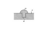
ここで、超音波処置具1は、図5に示すように、可撓性プローブ3をインナシース11で覆うと共に、可撓性プローブ3の超音波振動における節位置に、インナシース11内面に当接する防振部材12を設けてもよい。可撓性プローブ3をインナシース11で覆うと、超音波処置具1は、可撓性プローブ3と鉗子5の開閉操作によって図中左右方向に動く操作ワイヤ6とがインナシース11によって隔離されるため、可撓性プローブ3と操作ワイヤ6とがシース7内で干渉して絡まることが防止される。 Here, as shown in FIG. 5, the
また、可撓性プローブ3に防振部材12を設けると、可撓性プローブ3を伝達される超音波の振動に起因して可撓性プローブ3に発生するノイズ振動が抑制され、超音波の振動を安定して伝達することができる。このとき、防振部材12は、耐熱性を有するフッ素樹脂,ポリイミド,ゴム等からなる素材を使用し、図6に示すように、可撓性プローブ3に周方向に形成した凹部3cに取り付ける。 In addition, when the
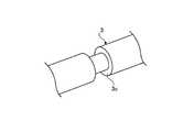
ここで、防振部材12は、図7に示すように、可撓性プローブ3に周方向に形成される凹部3cを、可撓性プローブ3の長手方向に沿って延びる長手状の溝とし、この溝に取り付けることで、超音波振動の節位置を含む前後数mmの範囲に設けてもよい。また、防振部材は、図8に示す防振部材13のように、可撓性プローブ3の外周に周方向に間隔をおいて設けてもよい。 Here, as shown in FIG. 7, the
以上のように、本発明にかかる超音波処置具は、処置部に剛性を付与したので、可撓性プローブを用いた超音波処置具に有用である。 As described above, the ultrasonic treatment instrument according to the present invention is useful for an ultrasonic treatment instrument using a flexible probe because rigidity is imparted to the treatment portion.
1 超音波処置
2 超音波振動子ユニット
3 可撓性プローブ
3a 処置部
3b 移行部
4 カバー部材
4a 取付面
4b 円筒部
4c 開口
5 鉗子
5c ピン
6 操作ワイヤ
7 シース
8 支持部材
9 操作ユニット
9a 支持筒
9b ガイド部材
9c 可動ハンドル
9d 固定ハンドル
9e,9f 指掛け孔
11 インナシース
12,13 防振部材DESCRIPTION OF
Claims (3)
Translated fromJapanese前記伝達部材の先端に処置部を設けると共に、前記処置部と係合して生体組織を把持し、操作ワイヤによって開閉される把持部材を前記処置部に設け、
前記処置部は、前記超音波の波長の略1/2の長さを有し、先端が前記超音波の振動における腹となり、前記超音波の伝達方向に直交する面における断面積を前記伝達部材よりも大きくして剛性が付与され、
前記把持部材は、前記超音波の振動における節位置において前記処置部と係合され、
前記操作ワイヤは、一端が前記把持部材に連結され、他端が操作部材に連結されて前記操作部材によって操作されることを特徴とする超音波処置具。An ultrasonic treatment tool that transmits ultrasonic waves generated by ultrasonic generation means to the tip of a flexible transmission member and performs ultrasonic treatment,
A treatment part is provided at the distal end of the transmission member, a living body is grasped by engaging with the treatment part, and a grasping member that is opened and closed by an operation wire is provided in the treatment part.
The treatment portion has a length approximately half of the wavelength of the ultrasonic wave, and a distal end becomes an antinode in the vibration of the ultrasonic wave, and a cross-sectional area in a plane orthogonal to the ultrasonic wave transmission direction is the transmission member. To give greater rigidity
The gripping member is engaged with the treatment portion at a node position in the ultrasonic vibration,
One end of the operation wire is connected to the grip member, and the other end is connected to the operation member, and the operation wire is operated by the operation member.
Priority Applications (4)
| Application Number | Priority Date | Filing Date | Title |
|---|---|---|---|
| JP2004124184AJP4291202B2 (en) | 2004-04-20 | 2004-04-20 | Ultrasonic treatment device |
| EP04821907AEP1738703A4 (en) | 2004-04-20 | 2004-11-12 | Ultrasonic treatment tool |
| PCT/JP2004/016877WO2005102197A1 (en) | 2004-04-20 | 2004-11-12 | Ultrasonic treatment tool |
| US11/474,843US20060247558A1 (en) | 2004-04-20 | 2006-06-26 | Ultrasonic treatment apparatus |
Applications Claiming Priority (1)
| Application Number | Priority Date | Filing Date | Title |
|---|---|---|---|
| JP2004124184AJP4291202B2 (en) | 2004-04-20 | 2004-04-20 | Ultrasonic treatment device |
Publications (2)
| Publication Number | Publication Date |
|---|---|
| JP2005304685A JP2005304685A (en) | 2005-11-04 |
| JP4291202B2true JP4291202B2 (en) | 2009-07-08 |
Family
ID=35196697
Family Applications (1)
| Application Number | Title | Priority Date | Filing Date |
|---|---|---|---|
| JP2004124184AExpired - LifetimeJP4291202B2 (en) | 2004-04-20 | 2004-04-20 | Ultrasonic treatment device |
Country Status (4)
| Country | Link |
|---|---|
| US (1) | US20060247558A1 (en) |
| EP (1) | EP1738703A4 (en) |
| JP (1) | JP4291202B2 (en) |
| WO (1) | WO2005102197A1 (en) |
Families Citing this family (140)
| Publication number | Priority date | Publication date | Assignee | Title |
|---|---|---|---|---|
| US11229472B2 (en) | 2001-06-12 | 2022-01-25 | Cilag Gmbh International | Modular battery powered handheld surgical instrument with multiple magnetic position sensors |
| JP4128496B2 (en)* | 2003-07-30 | 2008-07-30 | オリンパス株式会社 | Ultrasonic treatment device |
| US8182501B2 (en) | 2004-02-27 | 2012-05-22 | Ethicon Endo-Surgery, Inc. | Ultrasonic surgical shears and method for sealing a blood vessel using same |
| US20060079879A1 (en) | 2004-10-08 | 2006-04-13 | Faller Craig N | Actuation mechanism for use with an ultrasonic surgical instrument |
| US20070191713A1 (en) | 2005-10-14 | 2007-08-16 | Eichmann Stephen E | Ultrasonic device for cutting and coagulating |
| US20070167965A1 (en)* | 2006-01-05 | 2007-07-19 | Ethicon Endo-Surgery, Inc. | Ultrasonic medical instrument |
| US7621930B2 (en) | 2006-01-20 | 2009-11-24 | Ethicon Endo-Surgery, Inc. | Ultrasound medical instrument having a medical ultrasonic blade |
| US8057498B2 (en) | 2007-11-30 | 2011-11-15 | Ethicon Endo-Surgery, Inc. | Ultrasonic surgical instrument blades |
| US8226675B2 (en) | 2007-03-22 | 2012-07-24 | Ethicon Endo-Surgery, Inc. | Surgical instruments |
| US8911460B2 (en) | 2007-03-22 | 2014-12-16 | Ethicon Endo-Surgery, Inc. | Ultrasonic surgical instruments |
| US8142461B2 (en) | 2007-03-22 | 2012-03-27 | Ethicon Endo-Surgery, Inc. | Surgical instruments |
| US8808319B2 (en) | 2007-07-27 | 2014-08-19 | Ethicon Endo-Surgery, Inc. | Surgical instruments |
| US8523889B2 (en) | 2007-07-27 | 2013-09-03 | Ethicon Endo-Surgery, Inc. | Ultrasonic end effectors with increased active length |
| US8882791B2 (en) | 2007-07-27 | 2014-11-11 | Ethicon Endo-Surgery, Inc. | Ultrasonic surgical instruments |
| US8430898B2 (en) | 2007-07-31 | 2013-04-30 | Ethicon Endo-Surgery, Inc. | Ultrasonic surgical instruments |
| US8512365B2 (en) | 2007-07-31 | 2013-08-20 | Ethicon Endo-Surgery, Inc. | Surgical instruments |
| US9044261B2 (en) | 2007-07-31 | 2015-06-02 | Ethicon Endo-Surgery, Inc. | Temperature controlled ultrasonic surgical instruments |
| EP2217157A2 (en) | 2007-10-05 | 2010-08-18 | Ethicon Endo-Surgery, Inc. | Ergonomic surgical instruments |
| US10010339B2 (en) | 2007-11-30 | 2018-07-03 | Ethicon Llc | Ultrasonic surgical blades |
| US9089360B2 (en) | 2008-08-06 | 2015-07-28 | Ethicon Endo-Surgery, Inc. | Devices and techniques for cutting and coagulating tissue |
| JP5382685B2 (en)* | 2008-10-31 | 2014-01-08 | 公立大学法人首都大学東京 | Ultrasonic probe and ultrasonic diagnostic apparatus |
| US9700339B2 (en) | 2009-05-20 | 2017-07-11 | Ethicon Endo-Surgery, Inc. | Coupling arrangements and methods for attaching tools to ultrasonic surgical instruments |
| US8663220B2 (en) | 2009-07-15 | 2014-03-04 | Ethicon Endo-Surgery, Inc. | Ultrasonic surgical instruments |
| US11090104B2 (en) | 2009-10-09 | 2021-08-17 | Cilag Gmbh International | Surgical generator for ultrasonic and electrosurgical devices |
| USRE47996E1 (en) | 2009-10-09 | 2020-05-19 | Ethicon Llc | Surgical generator for ultrasonic and electrosurgical devices |
| US9168054B2 (en) | 2009-10-09 | 2015-10-27 | Ethicon Endo-Surgery, Inc. | Surgical generator for ultrasonic and electrosurgical devices |
| US9050093B2 (en) | 2009-10-09 | 2015-06-09 | Ethicon Endo-Surgery, Inc. | Surgical generator for ultrasonic and electrosurgical devices |
| US10441345B2 (en) | 2009-10-09 | 2019-10-15 | Ethicon Llc | Surgical generator for ultrasonic and electrosurgical devices |
| US8951272B2 (en) | 2010-02-11 | 2015-02-10 | Ethicon Endo-Surgery, Inc. | Seal arrangements for ultrasonically powered surgical instruments |
| US8961547B2 (en) | 2010-02-11 | 2015-02-24 | Ethicon Endo-Surgery, Inc. | Ultrasonic surgical instruments with moving cutting implement |
| US8469981B2 (en) | 2010-02-11 | 2013-06-25 | Ethicon Endo-Surgery, Inc. | Rotatable cutting implement arrangements for ultrasonic surgical instruments |
| US8486096B2 (en) | 2010-02-11 | 2013-07-16 | Ethicon Endo-Surgery, Inc. | Dual purpose surgical instrument for cutting and coagulating tissue |
| US8579928B2 (en) | 2010-02-11 | 2013-11-12 | Ethicon Endo-Surgery, Inc. | Outer sheath and blade arrangements for ultrasonic surgical instruments |
| GB2480498A (en) | 2010-05-21 | 2011-11-23 | Ethicon Endo Surgery Inc | Medical device comprising RF circuitry |
| US8795327B2 (en) | 2010-07-22 | 2014-08-05 | Ethicon Endo-Surgery, Inc. | Electrosurgical instrument with separate closure and cutting members |
| US9192431B2 (en) | 2010-07-23 | 2015-11-24 | Ethicon Endo-Surgery, Inc. | Electrosurgical cutting and sealing instrument |
| US9259265B2 (en) | 2011-07-22 | 2016-02-16 | Ethicon Endo-Surgery, Llc | Surgical instruments for tensioning tissue |
| WO2013119545A1 (en) | 2012-02-10 | 2013-08-15 | Ethicon-Endo Surgery, Inc. | Robotically controlled surgical instrument |
| US9724118B2 (en) | 2012-04-09 | 2017-08-08 | Ethicon Endo-Surgery, Llc | Techniques for cutting and coagulating tissue for ultrasonic surgical instruments |
| US9237921B2 (en) | 2012-04-09 | 2016-01-19 | Ethicon Endo-Surgery, Inc. | Devices and techniques for cutting and coagulating tissue |
| US9439668B2 (en) | 2012-04-09 | 2016-09-13 | Ethicon Endo-Surgery, Llc | Switch arrangements for ultrasonic surgical instruments |
| US9241731B2 (en) | 2012-04-09 | 2016-01-26 | Ethicon Endo-Surgery, Inc. | Rotatable electrical connection for ultrasonic surgical instruments |
| US20140005705A1 (en) | 2012-06-29 | 2014-01-02 | Ethicon Endo-Surgery, Inc. | Surgical instruments with articulating shafts |
| US9408622B2 (en) | 2012-06-29 | 2016-08-09 | Ethicon Endo-Surgery, Llc | Surgical instruments with articulating shafts |
| US9226767B2 (en) | 2012-06-29 | 2016-01-05 | Ethicon Endo-Surgery, Inc. | Closed feedback control for electrosurgical device |
| US9351754B2 (en) | 2012-06-29 | 2016-05-31 | Ethicon Endo-Surgery, Llc | Ultrasonic surgical instruments with distally positioned jaw assemblies |
| US9326788B2 (en) | 2012-06-29 | 2016-05-03 | Ethicon Endo-Surgery, Llc | Lockout mechanism for use with robotic electrosurgical device |
| US9820768B2 (en) | 2012-06-29 | 2017-11-21 | Ethicon Llc | Ultrasonic surgical instruments with control mechanisms |
| US9393037B2 (en) | 2012-06-29 | 2016-07-19 | Ethicon Endo-Surgery, Llc | Surgical instruments with articulating shafts |
| US9283045B2 (en) | 2012-06-29 | 2016-03-15 | Ethicon Endo-Surgery, Llc | Surgical instruments with fluid management system |
| US9198714B2 (en) | 2012-06-29 | 2015-12-01 | Ethicon Endo-Surgery, Inc. | Haptic feedback devices for surgical robot |
| US20140005702A1 (en) | 2012-06-29 | 2014-01-02 | Ethicon Endo-Surgery, Inc. | Ultrasonic surgical instruments with distally positioned transducers |
| CN102813550B (en)* | 2012-08-27 | 2014-08-13 | 杭州电子科技大学 | Electronic control bending device of tool bit of ultrasonic scalpel |
| EP2900158B1 (en) | 2012-09-28 | 2020-04-15 | Ethicon LLC | Multi-function bi-polar forceps |
| US10201365B2 (en) | 2012-10-22 | 2019-02-12 | Ethicon Llc | Surgeon feedback sensing and display methods |
| US9095367B2 (en) | 2012-10-22 | 2015-08-04 | Ethicon Endo-Surgery, Inc. | Flexible harmonic waveguides/blades for surgical instruments |
| US20140135804A1 (en) | 2012-11-15 | 2014-05-15 | Ethicon Endo-Surgery, Inc. | Ultrasonic and electrosurgical devices |
| JP5750670B2 (en) | 2012-12-13 | 2015-07-22 | オリンパス株式会社 | Treatment equipment |
| US10226273B2 (en) | 2013-03-14 | 2019-03-12 | Ethicon Llc | Mechanical fasteners for use with surgical energy devices |
| US9241728B2 (en) | 2013-03-15 | 2016-01-26 | Ethicon Endo-Surgery, Inc. | Surgical instrument with multiple clamping mechanisms |
| NO347629B1 (en) | 2013-04-02 | 2024-02-05 | Logined Bv | Processing seismic attributes using mathematical morphology |
| US9814514B2 (en) | 2013-09-13 | 2017-11-14 | Ethicon Llc | Electrosurgical (RF) medical instruments for cutting and coagulating tissue |
| US9265926B2 (en) | 2013-11-08 | 2016-02-23 | Ethicon Endo-Surgery, Llc | Electrosurgical devices |
| GB2521229A (en) | 2013-12-16 | 2015-06-17 | Ethicon Endo Surgery Inc | Medical device |
| GB2521228A (en) | 2013-12-16 | 2015-06-17 | Ethicon Endo Surgery Inc | Medical device |
| US9795436B2 (en) | 2014-01-07 | 2017-10-24 | Ethicon Llc | Harvesting energy from a surgical generator |
| US9554854B2 (en) | 2014-03-18 | 2017-01-31 | Ethicon Endo-Surgery, Llc | Detecting short circuits in electrosurgical medical devices |
| US10092310B2 (en) | 2014-03-27 | 2018-10-09 | Ethicon Llc | Electrosurgical devices |
| US10463421B2 (en) | 2014-03-27 | 2019-11-05 | Ethicon Llc | Two stage trigger, clamp and cut bipolar vessel sealer |
| US9737355B2 (en) | 2014-03-31 | 2017-08-22 | Ethicon Llc | Controlling impedance rise in electrosurgical medical devices |
| US9913680B2 (en) | 2014-04-15 | 2018-03-13 | Ethicon Llc | Software algorithms for electrosurgical instruments |
| US10285724B2 (en) | 2014-07-31 | 2019-05-14 | Ethicon Llc | Actuation mechanisms and load adjustment assemblies for surgical instruments |
| US10639092B2 (en) | 2014-12-08 | 2020-05-05 | Ethicon Llc | Electrode configurations for surgical instruments |
| US10245095B2 (en) | 2015-02-06 | 2019-04-02 | Ethicon Llc | Electrosurgical instrument with rotation and articulation mechanisms |
| US10342602B2 (en) | 2015-03-17 | 2019-07-09 | Ethicon Llc | Managing tissue treatment |
| US10321950B2 (en) | 2015-03-17 | 2019-06-18 | Ethicon Llc | Managing tissue treatment |
| US10595929B2 (en) | 2015-03-24 | 2020-03-24 | Ethicon Llc | Surgical instruments with firing system overload protection mechanisms |
| US10034684B2 (en) | 2015-06-15 | 2018-07-31 | Ethicon Llc | Apparatus and method for dissecting and coagulating tissue |
| US11020140B2 (en) | 2015-06-17 | 2021-06-01 | Cilag Gmbh International | Ultrasonic surgical blade for use with ultrasonic surgical instruments |
| US10898256B2 (en) | 2015-06-30 | 2021-01-26 | Ethicon Llc | Surgical system with user adaptable techniques based on tissue impedance |
| US10034704B2 (en) | 2015-06-30 | 2018-07-31 | Ethicon Llc | Surgical instrument with user adaptable algorithms |
| US11051873B2 (en) | 2015-06-30 | 2021-07-06 | Cilag Gmbh International | Surgical system with user adaptable techniques employing multiple energy modalities based on tissue parameters |
| US10357303B2 (en) | 2015-06-30 | 2019-07-23 | Ethicon Llc | Translatable outer tube for sealing using shielded lap chole dissector |
| US11141213B2 (en) | 2015-06-30 | 2021-10-12 | Cilag Gmbh International | Surgical instrument with user adaptable techniques |
| US11129669B2 (en) | 2015-06-30 | 2021-09-28 | Cilag Gmbh International | Surgical system with user adaptable techniques based on tissue type |
| US10154852B2 (en) | 2015-07-01 | 2018-12-18 | Ethicon Llc | Ultrasonic surgical blade with improved cutting and coagulation features |
| US10194973B2 (en) | 2015-09-30 | 2019-02-05 | Ethicon Llc | Generator for digitally generating electrical signal waveforms for electrosurgical and ultrasonic surgical instruments |
| US10595930B2 (en) | 2015-10-16 | 2020-03-24 | Ethicon Llc | Electrode wiping surgical device |
| US10179022B2 (en) | 2015-12-30 | 2019-01-15 | Ethicon Llc | Jaw position impedance limiter for electrosurgical instrument |
| US10575892B2 (en) | 2015-12-31 | 2020-03-03 | Ethicon Llc | Adapter for electrical surgical instruments |
| US10716615B2 (en) | 2016-01-15 | 2020-07-21 | Ethicon Llc | Modular battery powered handheld surgical instrument with curved end effectors having asymmetric engagement between jaw and blade |
| US11229471B2 (en) | 2016-01-15 | 2022-01-25 | Cilag Gmbh International | Modular battery powered handheld surgical instrument with selective application of energy based on tissue characterization |
| US11051840B2 (en) | 2016-01-15 | 2021-07-06 | Ethicon Llc | Modular battery powered handheld surgical instrument with reusable asymmetric handle housing |
| US11129670B2 (en) | 2016-01-15 | 2021-09-28 | Cilag Gmbh International | Modular battery powered handheld surgical instrument with selective application of energy based on button displacement, intensity, or local tissue characterization |
| US12193698B2 (en) | 2016-01-15 | 2025-01-14 | Cilag Gmbh International | Method for self-diagnosing operation of a control switch in a surgical instrument system |
| US10555769B2 (en) | 2016-02-22 | 2020-02-11 | Ethicon Llc | Flexible circuits for electrosurgical instrument |
| US10485607B2 (en) | 2016-04-29 | 2019-11-26 | Ethicon Llc | Jaw structure with distal closure for electrosurgical instruments |
| US10702329B2 (en) | 2016-04-29 | 2020-07-07 | Ethicon Llc | Jaw structure with distal post for electrosurgical instruments |
| US10646269B2 (en) | 2016-04-29 | 2020-05-12 | Ethicon Llc | Non-linear jaw gap for electrosurgical instruments |
| US10456193B2 (en) | 2016-05-03 | 2019-10-29 | Ethicon Llc | Medical device with a bilateral jaw configuration for nerve stimulation |
| US10245064B2 (en) | 2016-07-12 | 2019-04-02 | Ethicon Llc | Ultrasonic surgical instrument with piezoelectric central lumen transducer |
| US10893883B2 (en) | 2016-07-13 | 2021-01-19 | Ethicon Llc | Ultrasonic assembly for use with ultrasonic surgical instruments |
| US10842522B2 (en) | 2016-07-15 | 2020-11-24 | Ethicon Llc | Ultrasonic surgical instruments having offset blades |
| US10376305B2 (en) | 2016-08-05 | 2019-08-13 | Ethicon Llc | Methods and systems for advanced harmonic energy |
| US10285723B2 (en) | 2016-08-09 | 2019-05-14 | Ethicon Llc | Ultrasonic surgical blade with improved heel portion |
| USD847990S1 (en) | 2016-08-16 | 2019-05-07 | Ethicon Llc | Surgical instrument |
| US10736649B2 (en) | 2016-08-25 | 2020-08-11 | Ethicon Llc | Electrical and thermal connections for ultrasonic transducer |
| US10952759B2 (en) | 2016-08-25 | 2021-03-23 | Ethicon Llc | Tissue loading of a surgical instrument |
| US10751117B2 (en) | 2016-09-23 | 2020-08-25 | Ethicon Llc | Electrosurgical instrument with fluid diverter |
| US10603064B2 (en) | 2016-11-28 | 2020-03-31 | Ethicon Llc | Ultrasonic transducer |
| US11266430B2 (en) | 2016-11-29 | 2022-03-08 | Cilag Gmbh International | End effector control and calibration |
| US10799284B2 (en) | 2017-03-15 | 2020-10-13 | Ethicon Llc | Electrosurgical instrument with textured jaws |
| US10820920B2 (en) | 2017-07-05 | 2020-11-03 | Ethicon Llc | Reusable ultrasonic medical devices and methods of their use |
| WO2019224952A1 (en)* | 2018-05-23 | 2019-11-28 | オリンパス株式会社 | Treatment tool re-processing method |
| US20210196357A1 (en) | 2019-12-30 | 2021-07-01 | Ethicon Llc | Electrosurgical instrument with asynchronous energizing electrodes |
| US11779387B2 (en) | 2019-12-30 | 2023-10-10 | Cilag Gmbh International | Clamp arm jaw to minimize tissue sticking and improve tissue control |
| US12114912B2 (en) | 2019-12-30 | 2024-10-15 | Cilag Gmbh International | Non-biased deflectable electrode to minimize contact between ultrasonic blade and electrode |
| US12336747B2 (en) | 2019-12-30 | 2025-06-24 | Cilag Gmbh International | Method of operating a combination ultrasonic / bipolar RF surgical device with a combination energy modality end-effector |
| US11684412B2 (en) | 2019-12-30 | 2023-06-27 | Cilag Gmbh International | Surgical instrument with rotatable and articulatable surgical end effector |
| US11950797B2 (en) | 2019-12-30 | 2024-04-09 | Cilag Gmbh International | Deflectable electrode with higher distal bias relative to proximal bias |
| US20210196362A1 (en) | 2019-12-30 | 2021-07-01 | Ethicon Llc | Electrosurgical end effectors with thermally insulative and thermally conductive portions |
| US11452525B2 (en) | 2019-12-30 | 2022-09-27 | Cilag Gmbh International | Surgical instrument comprising an adjustment system |
| US12343063B2 (en) | 2019-12-30 | 2025-07-01 | Cilag Gmbh International | Multi-layer clamp arm pad for enhanced versatility and performance of a surgical device |
| US12076006B2 (en) | 2019-12-30 | 2024-09-03 | Cilag Gmbh International | Surgical instrument comprising an orientation detection system |
| US11696776B2 (en) | 2019-12-30 | 2023-07-11 | Cilag Gmbh International | Articulatable surgical instrument |
| US11786291B2 (en) | 2019-12-30 | 2023-10-17 | Cilag Gmbh International | Deflectable support of RF energy electrode with respect to opposing ultrasonic blade |
| US12064109B2 (en) | 2019-12-30 | 2024-08-20 | Cilag Gmbh International | Surgical instrument comprising a feedback control circuit |
| US11779329B2 (en) | 2019-12-30 | 2023-10-10 | Cilag Gmbh International | Surgical instrument comprising a flex circuit including a sensor system |
| US12053224B2 (en) | 2019-12-30 | 2024-08-06 | Cilag Gmbh International | Variation in electrode parameters and deflectable electrode to modify energy density and tissue interaction |
| US11937866B2 (en) | 2019-12-30 | 2024-03-26 | Cilag Gmbh International | Method for an electrosurgical procedure |
| US11937863B2 (en) | 2019-12-30 | 2024-03-26 | Cilag Gmbh International | Deflectable electrode with variable compression bias along the length of the deflectable electrode |
| US11911063B2 (en) | 2019-12-30 | 2024-02-27 | Cilag Gmbh International | Techniques for detecting ultrasonic blade to electrode contact and reducing power to ultrasonic blade |
| US11812957B2 (en) | 2019-12-30 | 2023-11-14 | Cilag Gmbh International | Surgical instrument comprising a signal interference resolution system |
| US11986201B2 (en) | 2019-12-30 | 2024-05-21 | Cilag Gmbh International | Method for operating a surgical instrument |
| US12082808B2 (en) | 2019-12-30 | 2024-09-10 | Cilag Gmbh International | Surgical instrument comprising a control system responsive to software configurations |
| US12262937B2 (en) | 2019-12-30 | 2025-04-01 | Cilag Gmbh International | User interface for surgical instrument with combination energy modality end-effector |
| US11786294B2 (en) | 2019-12-30 | 2023-10-17 | Cilag Gmbh International | Control program for modular combination energy device |
| US12023086B2 (en) | 2019-12-30 | 2024-07-02 | Cilag Gmbh International | Electrosurgical instrument for delivering blended energy modalities to tissue |
| US11944366B2 (en) | 2019-12-30 | 2024-04-02 | Cilag Gmbh International | Asymmetric segmented ultrasonic support pad for cooperative engagement with a movable RF electrode |
| US11660089B2 (en) | 2019-12-30 | 2023-05-30 | Cilag Gmbh International | Surgical instrument comprising a sensing system |
Family Cites Families (20)
| Publication number | Priority date | Publication date | Assignee | Title |
|---|---|---|---|---|
| JPS62292150A (en)* | 1986-06-13 | 1987-12-18 | オリンパス光学工業株式会社 | Ultrasonic transmitting medium for treatment in cavity |
| US5322055B1 (en) | 1993-01-27 | 1997-10-14 | Ultracision Inc | Clamp coagulator/cutting system for ultrasonic surgical instruments |
| FR2715588B1 (en) | 1994-02-03 | 1996-03-01 | Aerospatiale | Ultrasonic percussion device. |
| JP3989030B2 (en)* | 1995-04-06 | 2007-10-10 | オリンパス株式会社 | Ultrasonic incision coagulator |
| US6669690B1 (en)* | 1995-04-06 | 2003-12-30 | Olympus Optical Co., Ltd. | Ultrasound treatment system |
| US6129735A (en)* | 1996-06-21 | 2000-10-10 | Olympus Optical Co., Ltd. | Ultrasonic treatment appliance |
| US6063098A (en)* | 1996-12-23 | 2000-05-16 | Houser; Kevin | Articulable ultrasonic surgical apparatus |
| US5989275A (en)* | 1997-02-28 | 1999-11-23 | Ethicon Endo-Surgery, Inc. | Damping ultrasonic transmission components |
| US5980510A (en)* | 1997-10-10 | 1999-11-09 | Ethicon Endo-Surgery, Inc. | Ultrasonic clamp coagulator apparatus having improved clamp arm pivot mount |
| JP3489416B2 (en) | 1997-10-17 | 2004-01-19 | トヨタ自動車株式会社 | In-vehicle equipment control system and in-vehicle equipment control device |
| US5897523A (en)* | 1998-04-13 | 1999-04-27 | Ethicon Endo-Surgery, Inc. | Articulating ultrasonic surgical instrument |
| JP3537387B2 (en)* | 1998-04-16 | 2004-06-14 | オリンパス株式会社 | Ultrasonic treatment tool |
| US6193709B1 (en)* | 1998-05-13 | 2001-02-27 | Olympus Optical Co., Ltd. | Ultrasonic treatment apparatus |
| US5989264A (en)* | 1998-06-11 | 1999-11-23 | Ethicon Endo-Surgery, Inc. | Ultrasonic polyp snare |
| US6231578B1 (en) | 1998-08-05 | 2001-05-15 | United States Surgical Corporation | Ultrasonic snare for excising tissue |
| US6254623B1 (en)* | 1999-06-30 | 2001-07-03 | Ethicon Endo-Surgery, Inc. | Ultrasonic clamp coagulator surgical instrument with improved blade geometry |
| JP2001346806A (en)* | 2000-04-07 | 2001-12-18 | Olympus Optical Co Ltd | Ultrasonic resectoscope |
| JP2002085420A (en)* | 2000-09-19 | 2002-03-26 | Olympus Optical Co Ltd | Apparatus and method for ultrasonic coagulating and incising |
| US6893434B2 (en) | 2002-05-13 | 2005-05-17 | Axya Medical, Inc. | Ultrasonic soft tissue cutting and coagulation systems including a retractable grasper |
| JP2004000336A (en)* | 2002-05-31 | 2004-01-08 | Olympus Corp | Ultrasonic treatment apparatus |
- 2004
- 2004-04-20JPJP2004124184Apatent/JP4291202B2/ennot_activeExpired - Lifetime
- 2004-11-12EPEP04821907Apatent/EP1738703A4/ennot_activeWithdrawn
- 2004-11-12WOPCT/JP2004/016877patent/WO2005102197A1/ennot_activeApplication Discontinuation
- 2006
- 2006-06-26USUS11/474,843patent/US20060247558A1/ennot_activeAbandoned
Also Published As
| Publication number | Publication date |
|---|---|
| JP2005304685A (en) | 2005-11-04 |
| EP1738703A4 (en) | 2010-08-25 |
| US20060247558A1 (en) | 2006-11-02 |
| EP1738703A1 (en) | 2007-01-03 |
| WO2005102197A1 (en) | 2005-11-03 |
Similar Documents
| Publication | Publication Date | Title |
|---|---|---|
| JP4291202B2 (en) | Ultrasonic treatment device | |
| JP5322721B2 (en) | Surgical equipment | |
| JP4976597B2 (en) | Ultrasonic treatment device | |
| JP3704399B2 (en) | Ultrasonic treatment device | |
| JP5215216B2 (en) | Surgical equipment | |
| JP3600070B2 (en) | Ultrasonic treatment tool | |
| JP5164877B2 (en) | Ultrasonic treatment device | |
| JP4388475B2 (en) | Ultrasonic treatment device | |
| KR101055526B1 (en) | Surgical surgical device | |
| JP2009261911A (en) | Surgical operating apparatus | |
| JP2005278935A (en) | Ultrasonic treatment apparatus | |
| KR102106746B1 (en) | laparoscopic instrument | |
| JP3354032B2 (en) | Surgical forceps and ultrasonic coagulation and incision device | |
| CN100522086C (en) | Ultrasonic wave disposal apparatus | |
| JP2007313315A (en) | Medical device actuators | |
| JP3238138B2 (en) | Ultrasonic treatment equipment | |
| JP2010167204A (en) | Ultrasonic treatment system | |
| JP2004033565A (en) | Ultrasonic treatment instrument | |
| JP3922912B2 (en) | Ultrasonic treatment device | |
| JPH105238A (en) | Ultrasonic treater | |
| JPH08275952A (en) | Ultrasonic dissecting and coagulating device | |
| JP4323204B2 (en) | Ultrasonic treatment device | |
| JP4276873B2 (en) | Ultrasonic treatment device | |
| JP2004305587A (en) | Ultrasonic treating apparatus | |
| JP2002159506A (en) | Ultrasonic treatment device |
Legal Events
| Date | Code | Title | Description |
|---|---|---|---|
| A621 | Written request for application examination | Free format text:JAPANESE INTERMEDIATE CODE: A621 Effective date:20051228 | |
| A131 | Notification of reasons for refusal | Free format text:JAPANESE INTERMEDIATE CODE: A131 Effective date:20080902 | |
| TRDD | Decision of grant or rejection written | ||
| A01 | Written decision to grant a patent or to grant a registration (utility model) | Free format text:JAPANESE INTERMEDIATE CODE: A01 Effective date:20090310 | |
| A01 | Written decision to grant a patent or to grant a registration (utility model) | Free format text:JAPANESE INTERMEDIATE CODE: A01 | |
| A61 | First payment of annual fees (during grant procedure) | Free format text:JAPANESE INTERMEDIATE CODE: A61 Effective date:20090402 | |
| FPAY | Renewal fee payment (event date is renewal date of database) | Free format text:PAYMENT UNTIL: 20120410 Year of fee payment:3 | |
| FPAY | Renewal fee payment (event date is renewal date of database) | Free format text:PAYMENT UNTIL: 20120410 Year of fee payment:3 | |
| FPAY | Renewal fee payment (event date is renewal date of database) | Free format text:PAYMENT UNTIL: 20130410 Year of fee payment:4 | |
| FPAY | Renewal fee payment (event date is renewal date of database) | Free format text:PAYMENT UNTIL: 20140410 Year of fee payment:5 | |
| S531 | Written request for registration of change of domicile | Free format text:JAPANESE INTERMEDIATE CODE: R313531 | |
| R350 | Written notification of registration of transfer | Free format text:JAPANESE INTERMEDIATE CODE: R350 | |
| R250 | Receipt of annual fees | Free format text:JAPANESE INTERMEDIATE CODE: R250 |