JP4291173B2 - Impact driver - Google Patents
Impact driverDownload PDFInfo
- Publication number
- JP4291173B2 JP4291173B2JP2004034016AJP2004034016AJP4291173B2JP 4291173 B2JP4291173 B2JP 4291173B2JP 2004034016 AJP2004034016 AJP 2004034016AJP 2004034016 AJP2004034016 AJP 2004034016AJP 4291173 B2JP4291173 B2JP 4291173B2
- Authority
- JP
- Japan
- Prior art keywords
- output shaft
- cam
- anvil
- chuck sleeve
- impact driver
- Prior art date
- Legal status (The legal status is an assumption and is not a legal conclusion. Google has not performed a legal analysis and makes no representation as to the accuracy of the status listed.)
- Expired - Fee Related
Links
- 230000007246mechanismEffects0.000claimsdescription19
- 230000001105regulatory effectEffects0.000claimsdescription5
- 230000002093peripheral effectEffects0.000description6
- 230000009471actionEffects0.000description3
- 210000000078clawAnatomy0.000description3
- 238000005553drillingMethods0.000description3
- 230000006872improvementEffects0.000description3
- 229910000831SteelInorganic materials0.000description2
- 230000008859changeEffects0.000description2
- 230000000694effectsEffects0.000description2
- 239000010959steelSubstances0.000description2
- 230000003466anti-cipated effectEffects0.000description1
- 230000008901benefitEffects0.000description1
- 238000005096rolling processMethods0.000description1
- 238000000926separation methodMethods0.000description1
Images


Classifications
- B—PERFORMING OPERATIONS; TRANSPORTING
- B25—HAND TOOLS; PORTABLE POWER-DRIVEN TOOLS; MANIPULATORS
- B25B—TOOLS OR BENCH DEVICES NOT OTHERWISE PROVIDED FOR, FOR FASTENING, CONNECTING, DISENGAGING OR HOLDING
- B25B21/00—Portable power-driven screw or nut setting or loosening tools; Attachments for drilling apparatus serving the same purpose
- B25B21/02—Portable power-driven screw or nut setting or loosening tools; Attachments for drilling apparatus serving the same purpose with means for imparting impact to screwdriver blade or nut socket
- B—PERFORMING OPERATIONS; TRANSPORTING
- B25—HAND TOOLS; PORTABLE POWER-DRIVEN TOOLS; MANIPULATORS
- B25B—TOOLS OR BENCH DEVICES NOT OTHERWISE PROVIDED FOR, FOR FASTENING, CONNECTING, DISENGAGING OR HOLDING
- B25B21/00—Portable power-driven screw or nut setting or loosening tools; Attachments for drilling apparatus serving the same purpose
- B25B21/02—Portable power-driven screw or nut setting or loosening tools; Attachments for drilling apparatus serving the same purpose with means for imparting impact to screwdriver blade or nut socket
- B25B21/023—Portable power-driven screw or nut setting or loosening tools; Attachments for drilling apparatus serving the same purpose with means for imparting impact to screwdriver blade or nut socket for imparting an axial impact, e.g. for self-tapping screws
- B—PERFORMING OPERATIONS; TRANSPORTING
- B25—HAND TOOLS; PORTABLE POWER-DRIVEN TOOLS; MANIPULATORS
- B25D—PERCUSSIVE TOOLS
- B25D11/00—Portable percussive tools with electromotor or other motor drive
- B25D11/06—Means for driving the impulse member
- B25D11/10—Means for driving the impulse member comprising a cam mechanism
- B25D11/102—Means for driving the impulse member comprising a cam mechanism the rotating axis of the cam member being coaxial with the axis of the tool
- B—PERFORMING OPERATIONS; TRANSPORTING
- B25—HAND TOOLS; PORTABLE POWER-DRIVEN TOOLS; MANIPULATORS
- B25D—PERCUSSIVE TOOLS
- B25D16/00—Portable percussive machines with superimposed rotation, the rotational movement of the output shaft of a motor being modified to generate axial impacts on the tool bit
- B25D16/006—Mode changers; Mechanisms connected thereto
- B—PERFORMING OPERATIONS; TRANSPORTING
- B25—HAND TOOLS; PORTABLE POWER-DRIVEN TOOLS; MANIPULATORS
- B25D—PERCUSSIVE TOOLS
- B25D2216/00—Details of portable percussive machines with superimposed rotation, the rotational movement of the output shaft of a motor being modified to generate axial impacts on the tool bit
- B25D2216/0007—Details of percussion or rotation modes
- B25D2216/0023—Tools having a percussion-and-rotation mode
- B—PERFORMING OPERATIONS; TRANSPORTING
- B25—HAND TOOLS; PORTABLE POWER-DRIVEN TOOLS; MANIPULATORS
- B25D—PERCUSSIVE TOOLS
- B25D2216/00—Details of portable percussive machines with superimposed rotation, the rotational movement of the output shaft of a motor being modified to generate axial impacts on the tool bit
- B25D2216/0007—Details of percussion or rotation modes
- B25D2216/0038—Tools having a rotation-only mode
Landscapes
- Engineering & Computer Science (AREA)
- Mechanical Engineering (AREA)
- Percussive Tools And Related Accessories (AREA)
- Drilling And Boring (AREA)
Description
Translated fromJapanese本発明は、出力軸に回転と間歇的な打撃作動とを付与可能なインパクトドライバに関する。 The present invention relates to an impact driver capable of imparting rotation and intermittent hitting operation to an output shaft.
インパクトドライバは、ハウジングに内蔵したモータと、ハウジングから突出させた出力軸との間に、モータのトルクを出力軸へ伝達すると共に、出力軸への負荷に応じてその回転方向へ打撃作動を付与可能な回転打撃機構を設けている。この回転打撃機構としては、例えば特許文献1に開示のように、モータにより回転するスピンドルに、カム溝とボールとを介してハンマーを連結し、そのハンマーの前方に、ハンマーと回転方向で係脱可能なアンビル(出力軸)を設けて、スピンドルの回転をハンマーを介してアンビルへ伝達する構造が知られている。これは、アンビルへの負荷が一定値を超えると、ハンマーがカム溝に沿って後退してアンビルから一旦離脱し、前方へ付勢するコイルバネによってハンマーが再びカム溝に沿って前進しながらアンビルに係止するという作用を繰り返すことで、アンビルにその回転方向へ間歇的に打撃作動を付加可能としたものである。 The impact driver transmits the torque of the motor to the output shaft between the motor built in the housing and the output shaft protruding from the housing, and gives a striking action in the rotational direction according to the load on the output shaft. A possible rotary striking mechanism is provided. As this rotary striking mechanism, for example, as disclosed in Patent Document 1, a hammer is connected to a spindle rotated by a motor via a cam groove and a ball, and the hammer is engaged with and disengaged in the rotational direction in front of the hammer. There is known a structure in which a possible anvil (output shaft) is provided and the rotation of the spindle is transmitted to the anvil via a hammer. This is because when the load on the anvil exceeds a certain value, the hammer moves backward along the cam groove and temporarily leaves the anvil, and the hammer moves forward again along the cam groove by the coil spring biased forward. By repeating the action of locking, it is possible to add a striking operation intermittently in the direction of rotation of the anvil.
このようなインパクトドライバは、専らネジやボルト等による締着作業に使用されるが、例えば石膏板等の被加工材にアンカーボルトの締着作業を行うような場合は、まず震動ドリルを用いて被加工材に穿孔を行い、加工した孔にアンカーボルトをインパクトドライバを用いて締着する作業を行うことになる。よって、作業者は、震動ドリルとインパクトドライバとの2つの工具を使い分けることとなり、工具交換の手間が生じて作業性が良くなかった。 Such impact drivers are exclusively used for fastening work with screws, bolts, etc. For example, when performing fastening work of anchor bolts on workpieces such as plasterboard, first use a vibration drill. A work is performed in which a workpiece is perforated and an anchor bolt is fastened to the processed hole using an impact driver. Therefore, the operator uses two tools, ie, a vibration drill and an impact driver, and the work of replacing the tool is not good.
そこで、請求項1に記載の発明は、震動による穿孔作業も容易に行え、使い勝手に優れるインパクトドライバを提供することを目的としたものである。 SUMMARY OF THE INVENTION An object of the present invention is to provide an impact driver that can be easily drilled by vibration and is easy to use.
上記目的を達成するために、請求項1に記載の発明は、ハウジングに内蔵したモータと、前記ハウジングから突出させた出力軸との間に、前記モータのトルクを前記出力軸へ伝達すると共に、前記出力軸への負荷に応じてその回転方向へ打撃作動を付与可能な回転打撃機構を設けたインパクトドライバであって、前記出力軸を軸方向に前後へ微動可能に設け、前記出力軸の先端に、軸方向へのスライド操作で前記出力軸に工具を着脱可能なチャックスリーブを外装する一方、前記出力軸の回転に伴って前記出力軸に軸方向への震動を発生させる震動付与機構を、任意に選択可能に設けると共に、前記震動付与機構を、前記出力軸と別体で回転可能に外装され、前記チャックスリーブの一部が外装する第1カムと、その第1カムの後方で前記出力軸に遊挿され、前記ハウジング側へ固定される第2カムと、前記両カムの互いの対向面に形成され、前記出力軸の後退位置で互いに当接可能なカム歯と、前記チャックスリーブと出力軸との間に設けられ、前記チャックスリーブの回転操作によって前記第1カムの回転を任意に規制可能な規制手段とから構成することを特徴とするものである。In order to achieve the above object, according to the first aspect of the present invention, the torque of the motor is transmitted to the output shaft between the motor built in the housing and the output shaft protruding from the housing. An impact driver provided with a rotary striking mechanism capable of imparting a striking action in the rotational direction according to a load on the output shaft, wherein the output shaft is provided so as to be finely movable back and forth in the axial direction, andthe tip of the output shaft In addition, a vibration imparting mechanism for generating a vibration in the axial direction on the output shaft as the output shaft rotateswhile externally mounting a chuck sleeve on which the tool can be attached to and detached from the output shaft by a sliding operation in the axial direction, optionally provided selectableRutotomoni, the vibration applying mechanism, rotatably is sheathed with said output shaft and another member, a first cam portion of the chuck sleeve sheathing, the behind of the first cam Out A second cam that is loosely inserted into the shaft and fixed to the housing side, cam teeth that are formed on opposing surfaces of the two cams and that can come into contact with each other at the retracted position of the output shaft, and the chuck sleeve And a restricting means provided between the output shaft and capable of arbitrarily restricting the rotation of the first cam by rotating the chuck sleeve .
請求項2に記載の発明は、請求項1の目的に加えて、規制手段を操作しやすい位置で簡単に形成するために、規制手段を、出力軸の外周に形成された被係合部と、第1カムにその半径方向へ遊挿されて、チャックスリーブの回転操作に伴って出力軸に対して進退動し、前進位置で被係合部と係合する係合部材とから形成したものである。According to asecond aspect of the present invention, in addition to the object of thefirst aspect , in order to easily form the restricting means at a position where the restricting means can be easily operated, the restricting means includes an engaged portion formed on the outer periphery of the output shaft. The engagement member is inserted into the first cam in the radial direction, moves forward and backward with respect to the output shaft as the chuck sleeve rotates, and engages with the engaged portion at the forward position. It is.
請求項1に記載の発明によれば、震動付与機構によって震動付きモードの選択が可能となるため、穿孔作業とネジ締め作業とがインパクトドライバ一台で可能となり、作業性の向上が期待できる。
また、上記効果に加えて、チャックスリーブを規制手段に用いてモード切替の操作部材と兼用しているから、従来のインパクトドライバからの設計変更が少なく、より低コストで震動付与機構を形成できる利点がある。
請求項2に記載の発明によれば、請求項1の効果に加えて、出力軸前端の操作しやすい位置で規制手段を簡単に形成することができる。
According to the first aspect of the present invention, since the mode with vibration can be selected by the vibration applying mechanism, the drilling operation and the screw tightening operation can be performed with one impact driver, and improvement in workability can be expected.
In addition to the above effects, the chuck sleeve is used as a restricting means and also serves as a mode switching operation member, so that the design change from the conventional impact driver is less and the vibration imparting mechanism can be formed at a lower cost. There is.
According to thesecond aspect of the invention, in addition to the effect of thefirst aspect , the restricting means can be easily formed at a position where the front end of the output shaft is easy to operate.
以下、本発明の実施の形態を図面に基づいて説明する。
《形態1》
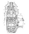
図1は、インパクトドライバの一例を示す一部縦断面図で、インパクトドライバ1は、モータ3を収容した本体ハウジング2の前方に、スピンドル6やハンマー7等を内蔵した前側のハウジングとなるハンマーケース5を組み付け、ハンマーケース5の前方に、出力軸としてのアンビル8を突出してなる。9はスイッチ、10はトリガーである。本体ハウジング2とハンマーケース5との間には、ギヤハウジング11が介在され、このギヤハウジング11が、モータ3のモータ軸4を軸支してハンマーケース5内に突出させると共に、スピンドル6の後端をボールベアリング12を介して軸支している。モータ軸4は、先端にピニオン13を嵌着すると共に、スピンドル6の後端に形成された中空部14へ同軸で遊挿し、スピンドル6の後方外周に軸着された複数の遊星歯車15,15・・と噛合して、モータ軸4の回転を減速してスピンドル6へ伝達可能となっている。Hereinafter, embodiments of the present invention will be described with reference to the drawings.
<< Form 1 >>
FIG. 1 is a partial longitudinal sectional view showing an example of an impact driver. The impact driver 1 is a hammer case serving as a front housing in which a
アンビル8は、ハンマーケース5の前端で軸受16によって回転可能に軸支されており、スピンドル6は、前端の小径部17がアンビル8の後面へ同軸で遊挿し、その小径部17の後方でハンマー7を外装している。ハンマー7は、スピンドル6の外周面で傾斜状に形成された一対のカム溝18,18と、ハンマー7の内周面で軸方向に形成された一対の連結溝19,19とに夫々跨って嵌挿される2つのスチールボール20,20とによってスピンドル6へ一体回転可能に連結されると共に、その後方でスピンドル6に外装されたコイルバネ21によって前方へ付勢されている。ハンマー7の前面には、アンビル8後端へ放射方向に延設された一対のアーム22,22に係合可能な一対の係合爪23,23が形成されて、図1に示すハンマー7の前進位置では、係合爪23,23がアーム22,22と係合してハンマー7とアンビル8とを回転方向で一体化させる。24は、アンビル8の先端に外装されたチャックスリーブで、常態ではコイルバネ25によって図1の後退位置へ付勢されて、アンビル8に内挿されたボール26,26をアンビル8の軸心側へ突出させ、ドライバビット等をアンビル8へ挿着する。 The
そして、ハンマーケース5において、アンビル8を軸支する前端の筒状部27の位置には、震動付与機構が設けられている。まず、アンビル8は、図2にも示すように、後端がスピンドル6の大径部に当接する後退位置と、アーム22,22の前方で外装されたワッシャー28がハンマーケース5に当接する前進位置との間で軸方向へ微動可能となっており、筒状部27の前端に近い部位には、後面にカム歯30,30・・を放射方向に形成した筒状の第1カム29が一体に外装され、その第1カム29の後方には、前面に同じくカム歯32,32・・を放射方向に形成した円盤状の第2カム31が回転可能に外装されている。この第2カム31は、筒状部27の内周後方に形成された段部33に受けられるフラットワッシャー34と、その前面でアンビル8の周面に沿って配置される複数のボール35,35・・とによって後退位置を規制され、アンビル8の後退位置で、第1カム29と第2カム31とのカム歯30,32同士が当接するようになっている。また、第2カム31の外周には、図3に示すように、軸方向の係止歯36,36・・が全周に亘って形成されている。 In the
一方、筒状部27には、内側端部が第2カム31の係止歯36に係合可能な係合部材としての係合ピン37が、筒状部27の放射方向で進退動可能に設けられている。この係合ピン37は、その外側端部のストッパ38と筒状部27外周との間で外装されたコイルバネ39によって、第2カム31からの離脱方向へ付勢される。筒状部27には、操作部材となる筒状のモード切替リング40が回転可能に外装されて、係合ピン37の突出位置を規制している。但し、モード切替リング40の内周面には、周方向の両側をテーパ面とした案内凹部41が形成されており、モード切替リング40の回転に伴い、案内凹部41を係合ピン37の位置とそこから周方向にずれた位置とに切り替えることで、係合ピン37の位置を変更可能としている。すなわち、案内凹部41が係合ピン37からずれた図3の回転位置では、係合ピン37はコイルバネ39の付勢に抗して中心側へ前進し、内側端部を第2カム31の係止歯36に係合させ(震動付きモード)、案内凹部41が係合ピン37の外側に位置する図4の回転位置では、係合ピン37はコイルバネ39の付勢によって外側へ後退し、内側端部を係止歯36から離脱させる(震動なしモード)。 On the other hand, the
以上の如く構成されたインパクトドライバ1においては、まずモード切替リング40を操作して震動なしモードを選択した場合、トリガー10の押し込み操作でスイッチ9をONさせ、モータ3を駆動させると、モータ軸4の回転が減速してスピンドル6へ伝わり、ハンマー7を介してアンビル8を回転させる。よって、アンビル8の先端に挿着したドライバビット等によってネジ締めが行える。ここで、ドライバビットの押し付けによってアンビル8は後退位置にあるため、アンビル8と一体回転する第1カム29が第2カム31と当接することになるが、係合ピン37が離脱している第2カム31は回転フリー状態であるため、第1カム29と一体に回転し、アンビル8に震動は発生しない。 In the impact driver 1 configured as described above, when the
ネジ締めが進んでアンビル8への負荷が高まると、スチールボール20,20をスピンドル6のカム溝18,18に沿って後方へ転動させながら、コイルバネ21の付勢に抗してハンマー7が後退し、アンビル8から外れる。しかし、アンビル8から外れた瞬間、コイルバネ21の付勢によって再びスピンドル6と共に回転しながら前進し、係合爪23,23をアンビル8のアーム22,22へ再係合させる。このハンマー7のアンビル8に対する離脱と係合との繰り返しにより、アンビル8へは回転方向へ間歇的に打撃作動(インパクト)が発生し、増し締めが可能となる。 When the screw tightening progresses and the load on the
一方、モード切替リング40を操作して震動付きモードを選択した場合、係合ピン37によって第2カム31の回転が規制されるため、後退位置で第1カム29がアンビル8と共に回転すると、回転規制される第2カム31と回転する第1カム29との互いのカム歯30,32同士が干渉し、第1カム29及びアンビル8に軸方向への震動を発生させる。ハンマー7によるインパクトの発生は同じであるため、ここでは震動+打撃が得られることになる。 On the other hand, when the mode with the vibration is selected by operating the
このように上記形態1のインパクトドライバ1によれば、アンビル8を軸方向に前後へ微動可能に設けると共に、アンビル8の回転に伴ってアンビル8に軸方向への震動を発生させる震動付与機構を、任意に選択可能に設けたことで、穿孔作業とネジ締め作業とがインパクトドライバ一台で可能となり、作業性の向上が期待できる。
特に、震動付与機構を、アンビル8に外装されて一体回転する第1カム29と、その第1カム29の後方にあってアンビル8に遊挿され、軸方向に移動規制される第2カム31と、両カム29,31の互いの対向面に形成され、アンビル8の後退位置で互いに当接可能なカム歯30,32と、ハンマーケース5の筒状部27に設けられ、第2カム31の回転をハンマーケース5の外部から任意に規制可能な規制手段とから形成したことで、震動付与機構が簡単に形成可能となる。As described above, according to the impact driver 1 of the first aspect, the
In particular, the vibration imparting mechanism includes a
また、規制手段を、筒状部27に外装されたモード切替リング40と、そのモード切替リング40の回転操作に伴って第2カム31に対して進退動し、前進位置で第2カム31と係合する係合ピン37とから形成したことで、操作しやすいハウジング前端で規制手段が簡単に形成可能となっている。 Further, the restricting means moves forward and backward with respect to the
なお、第2カムと係合部材との係合構造は、上記形態に限らず、第2カムの係止歯をよりピッチの広い突部に代えたり、係合部材を第2カムの周方向に長くして係合部分を広くしたり、係合部材を複数設けたり等の設計変更は可能である。また、操作部材は、モード切替リングのような筒状部材に限らず、半円や円弧状の部材としても良いし、ハウジングに形成された面取部上で直線的にスライド可能に設けられて係合部材を進退動させるスライド部材であっても差し支えない。
さらに、操作部材と筒状部との間に、震動付きモードと震動なしモードとの操作位置の目安となるクリック手段を設けたり、2つの操作位置でのみ操作可能な規制手段を設けたりすることができる。
加えて、係合部材は第2カムの周面に係合する構造としているが、第2カムの軸方向の前後面の何れかに係合部材を配置して、操作部材の操作で前後移動可能とし、第2カムの前後面に形成した凹部等の被係合部に係合部材を係脱させる構造も採用できる。Note that the engagement structure between the second cam and the engagement member is not limited to the above form, and the engaging teeth of the second cam are replaced with protrusions with a wider pitch, or the engagement member is in the circumferential direction of the second cam. It is possible to change the design such that the engagement portion is widened by increasing the length of the engagement portion or a plurality of engagement members are provided. Further, the operation member is not limited to a cylindrical member such as a mode switching ring, but may be a semicircular or arcuate member, and is provided to be linearly slidable on a chamfered portion formed in the housing. A slide member that moves the engagement member back and forth may be used.
Furthermore, between the operating member and the cylindrical portion, a click means that serves as a guide for the operation position in the mode with vibration and the mode without vibration is provided, or a restriction means that can be operated only at two operation positions is provided. Can do.
In addition, the engaging member is structured to engage with the peripheral surface of the second cam. However, the engaging member is arranged on any of the front and rear surfaces in the axial direction of the second cam, and is moved back and forth by operating the operating member. It is also possible to employ a structure in which the engaging member is engaged with and disengaged from an engaged portion such as a recess formed on the front and rear surfaces of the second cam.
《形態2》
次に、インパクトドライバの他の実施の形態を説明する。なお、形態1と同じ構成部は同じ符号を付して重複する説明を省略する。
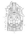
図5に示すインパクトドライバ1において、アンビル8には、前方から筒状の第1カム50と第2カム52とが夫々外装されている。第1カム50は、ハンマーケース5の筒状部27によって後方部分を軸支されて、アンビル8と別体で回転及び軸方向への移動が可能となっており、後面には、カム歯51,51・・が放射状に形成されている。また、第2カム52は、筒状部27に後方から圧入されてハンマーケース5と一体化され、アンビル8を軸支すると共に、後端に形成されたフランジ部53によってアンビル8の前進位置を規制している。よって、アンビル8は、アーム22,22がスピンドル6の大径部に当接する後退位置と、第2カム52のフランジ部53に当接する図5,6の前進位置との間で軸方向に微動可能となる。54,54・・は、第2カム52における第1カム50との対向面で放射状に形成されたカム歯である。<<
Next, another embodiment of the impact driver will be described. Note that the same components as those in the first embodiment are denoted by the same reference numerals and redundant description is omitted.
In the impact driver 1 shown in FIG. 5, a cylindrical
一方、第1カム50の前方部分には、チャックスリーブ24の後半部分に外装されると共に、係合部材となる一対の鍔付ピン55,55が、第1カム50の半径方向で進退動可能に遊挿されて、その前進位置で、アンビル8の周面で周方向に複数並設された被係合部としての凹部56,56・・に係合可能となっている。但し、図6に示すように、鍔付ピン55に外装されたコイルバネ57により、各鍔付ピン55は、上端がチャックスリーブ24の内面に当接する後退方向へ付勢されている。チャックスリーブ24の内面には、各鍔付ピン55の頭部と干渉可能で、周方向にテーパ面を形成した案内凸部58,58が突設されており、チャックスリーブ24の回転操作に伴い、案内凸部58,58を鍔付ピン55,55の位置と、そこから周方向にずれた位置とに切り替えることで、鍔付ピン55,55の進退位置を変更可能としている。 On the other hand, at the front portion of the
すなわち、案内凸部58が鍔付ピン55の外側に位置する図6の回転位置では、各鍔付ピン55はコイルバネ57の付勢に抗して中心側へ前進し、内側端部をアンビル8の凹部56に係合させ(震動付きモード)、案内凸部58が鍔付ピン55からずれた図7の回転位置では、鍔付ピン55はコイルバネ57の付勢によって外側へ後退し、内側端部を凹部56から離脱させる(震動なしモード)。なお、アンビル8にドライバビット等を着脱する際には、チャックスリーブ24をコイルバネ25の付勢に抗して前進させ、軸心側へ押圧していたボール26の規制を解除することになるが、このチャックスリーブ24の前進にかかわらず、鍔付ピン55の当接状態は変わらない設定となっている。 That is, in the rotational position of FIG. 6 in which the guide
以上の如く構成されたインパクトドライバ1においては、まずチャックスリーブ24を回転操作して震動なしモードを選択した場合、トリガー10の押し込み操作でスイッチ9をONさせ、モータ3を駆動させると、形態1と同様にアンビル8が回転し、負荷の増大に伴ってハンマー7による間歇的な打撃作動が加わる。ここで、アンビル8が後退位置にあっても、鍔付ピン55が凹部56に係合しない第1カム50は回転フリー状態であるため、第2カム52と当接してもアンビル8に震動は発生しない。
一方、チャックスリーブ24を回転操作して震動付きモードを選択した場合、鍔付ピン55,55によって第1カム50がアンビル8と結合される。よって、後退位置でアンビル8が回転すると、アンビル8と一体回転する第1カム50と第2カム52との互いのカム歯51,54同士が干渉し、第1カム50及びアンビル8に軸方向への震動を発生させ、震動+打撃が得られる。In the impact driver 1 configured as described above, when the no-vibration mode is selected by rotating the
On the other hand, when the
このように上記形態2のインパクトドライバ1においても、震動付与機構を選択可能に設けたことで、穿孔作業とネジ締め作業とがインパクトドライバ一台で可能となり、作業性の向上が期待できる。特に、震動付与機構を、アンビル8と別体で回転可能に外装され、チャックスリーブ24の一部が外装する第1カム50と、その第1カム50の後方でアンビル8に遊挿され、ハンマーケース5側へ固定される第2カム52と、両カム50,52の互いの対向面に形成され、アンビル8の後退位置で互いに当接可能なカム歯51,54と、チャックスリーブ24とアンビル8との間に設けられ、チャックスリーブ24の回転操作によって第1カム50の回転を任意に規制可能な規制手段とから形成して、ビット着脱用のチャックスリーブ24をモード切替リングと兼用しているから、従来のインパクトドライバからの設計変更が少なく、より低コストで震動付与機構を形成できる利点がある。 Thus, also in the impact driver 1 of the said
また、ここでも、規制手段を、アンビル8の外周に形成された凹部56と、第1カム50にその半径方向へ遊挿されて、チャックスリーブ24の回転操作に伴ってアンビル8に対して進退動し、前進位置で凹部56と係合する鍔付ピン55とから形成したことで、アンビル8前端のチャックスリーブ24を利用した規制手段が簡単に形成可能となっている。
なお、この形態2においても、鍔付ピンの数や形状、第1カムや第2カムの形状等は適宜変更可能で、チャックスリーブも、係合部材との当接部のみを部分的に延設したり、第1カムに外装されて係合部材が当接するスリーブを別体に装着したりすることができる。
勿論形態1と同様に、チャックスリーブとアンビルとの間に、震動付きモードと震動なしモードとの回転位置の目安となるクリック手段を設けたり、2つの回転位置でのみ回転可能な規制手段を設けたりすることもできる。Also in this case, the restricting means is loosely inserted in the radial direction of the
In the second embodiment as well, the number and shape of the hooked pins, the shapes of the first cam and the second cam, and the like can be changed as appropriate, and the chuck sleeve also partially extends only in the contact portion with the engaging member. Or a sleeve that is externally attached to the first cam and that is in contact with the engaging member can be mounted separately.
Needless to say, as in the first embodiment, a click means is provided between the chuck sleeve and the anvil as a guide for the rotational position between the vibration mode and the vibrationless mode, or a restriction means that can rotate only at the two rotational positions. You can also.
そして、上記形態1,2においては、アンビルへの打撃付与にハンマーを利用したインパクトドライバを例示しているが、入力される連続的なトルクを内部の油圧上昇に伴ってスピンドルへの間歇的なトルクとして出力可能なオイルユニットを用いたインパクトドライバであっても、スピンドル或いはオイルユニット全体を軸方向へ微動可能として、ハウジングとスピンドルとの間や、スピンドルとチャックスリーブとの間に形態1,2のような震動付与機構を形成することは可能である。
And in the said
1‥インパクトドライバ、2‥本体ハウジング、3‥モータ、5‥ハンマーケース、6‥スピンドル、7‥ハンマー、8‥アンビル、24‥チャックスリーブ、29,50‥第1カム、31,52‥第2カム、30,32,51,54‥カム歯、36‥係止歯、37‥係合ピン、40‥モード切替リング、41‥案内凹部、55‥鍔付ピン、56‥凹部、58‥案内凸部。
DESCRIPTION OF SYMBOLS 1 ... Impact driver, 2 ... Body housing, 3 ... Motor, 5 ... Hammer case, 6 ... Spindle, 7 ... Hammer, 8 ... Anvil, 24 ... Chuck sleeve, 29, 50 ... 1st cam, 31, 52 ... 2nd Cam, 30, 32, 51, 54 ... Cam teeth, 36 ... Locking teeth, 37 ... Engagement pin, 40 ... Mode switching ring, 41 ... Guide recess, 55 ... Brazed pin, 56 ... Recess, 58 ... Guide convex Department.
Claims (2)
Translated fromJapanese前記出力軸を軸方向に前後へ微動可能に設け、前記出力軸の先端に、軸方向へのスライド操作で前記出力軸に工具を着脱可能なチャックスリーブを外装する一方、
前記出力軸の回転に伴って前記出力軸に軸方向への震動を発生させる震動付与機構を、任意に選択可能に設けると共に、前記震動付与機構を、前記出力軸と別体で回転可能に外装され、前記チャックスリーブの一部が外装する第1カムと、その第1カムの後方で前記出力軸に遊挿され、前記ハウジング側へ固定される第2カムと、前記両カムの互いの対向面に形成され、前記出力軸の後退位置で互いに当接可能なカム歯と、前記チャックスリーブと出力軸との間に設けられ、前記チャックスリーブの回転操作によって前記第1カムの回転を任意に規制可能な規制手段とから構成することを特徴とするインパクトドライバ。Between the motor built in the housing and the output shaft protruding from the housing, the torque of the motor is transmitted to the output shaft, and a striking operation is given in the rotational direction according to the load on the output shaft. An impact driver with a possible rotary striking mechanism,
The output shaft is provided sothat it can be finely moved back and forthin the axial direction, and a chuck sleeve on which the tool can be attached to and detached from the output shaft by sliding operation in the axial direction is provided atthe tip of the output shaft,
The vibration applying mechanism for generating a vibration in the axial direction to the output shaft in accordance with rotation of the output shaft, optionally provided selectableRutotomoni, the vibration applying mechanism, rotatably with the output shaft and another member A first cam that is externally mounted and partially covered by the chuck sleeve; a second cam that is loosely inserted into the output shaft behind the first cam and fixed to the housing; and Cam teeth formed on opposing surfaces and capable of contacting each other at the retracted position of the output shaft, and provided between the chuck sleeve and the output shaft, and the first cam can be arbitrarily rotated by rotating the chuck sleeve. The impact driver is characterizedby comprising a regulating means that can be regulated .
Priority Applications (4)
| Application Number | Priority Date | Filing Date | Title |
|---|---|---|---|
| JP2004034016AJP4291173B2 (en) | 2004-02-10 | 2004-02-10 | Impact driver |
| US11/045,380US7131503B2 (en) | 2004-02-10 | 2005-01-31 | Impact driver having a percussion application mechanism which operation mode can be selectively switched between percussion and non-percussion modes |
| DE602005011504TDE602005011504D1 (en) | 2004-02-10 | 2005-02-08 | Impact tool with a hammer mechanism whose impact wrench mode can be selectively activated or deactivated |
| EP05002593AEP1563960B1 (en) | 2004-02-10 | 2005-02-08 | Impact driver having a percussion application mechanism which operation mode can be selectively switched between percussion and non-percussion mode |
Applications Claiming Priority (1)
| Application Number | Priority Date | Filing Date | Title |
|---|---|---|---|
| JP2004034016AJP4291173B2 (en) | 2004-02-10 | 2004-02-10 | Impact driver |
Publications (2)
| Publication Number | Publication Date |
|---|---|
| JP2005224881A JP2005224881A (en) | 2005-08-25 |
| JP4291173B2true JP4291173B2 (en) | 2009-07-08 |
Family
ID=34697886
Family Applications (1)
| Application Number | Title | Priority Date | Filing Date |
|---|---|---|---|
| JP2004034016AExpired - Fee RelatedJP4291173B2 (en) | 2004-02-10 | 2004-02-10 | Impact driver |
Country Status (4)
| Country | Link |
|---|---|
| US (1) | US7131503B2 (en) |
| EP (1) | EP1563960B1 (en) |
| JP (1) | JP4291173B2 (en) |
| DE (1) | DE602005011504D1 (en) |
Families Citing this family (60)
| Publication number | Priority date | Publication date | Assignee | Title |
|---|---|---|---|---|
| US7308948B2 (en) | 2004-10-28 | 2007-12-18 | Makita Corporation | Electric power tool |
| JP4643298B2 (en)* | 2005-02-14 | 2011-03-02 | 株式会社マキタ | Impact tool |
| DE102006045842A1 (en)* | 2006-09-27 | 2008-04-03 | Robert Bosch Gmbh | Hand tool |
| EP1961522B1 (en) | 2007-02-23 | 2015-04-08 | Robert Bosch Gmbh | Rotary power tool operable in either an impact mode or a drill mode |
| US7806198B2 (en) | 2007-06-15 | 2010-10-05 | Black & Decker Inc. | Hybrid impact tool |
| CA2606039C (en) | 2007-10-03 | 2016-03-29 | Camoplast Inc. | A track assembly for an all-terrain vehicle |
| US7798245B2 (en)* | 2007-11-21 | 2010-09-21 | Black & Decker Inc. | Multi-mode drill with an electronic switching arrangement |
| US7770660B2 (en)* | 2007-11-21 | 2010-08-10 | Black & Decker Inc. | Mid-handle drill construction and assembly process |
| US7717191B2 (en) | 2007-11-21 | 2010-05-18 | Black & Decker Inc. | Multi-mode hammer drill with shift lock |
| US7762349B2 (en) | 2007-11-21 | 2010-07-27 | Black & Decker Inc. | Multi-speed drill and transmission with low gear only clutch |
| US7854274B2 (en) | 2007-11-21 | 2010-12-21 | Black & Decker Inc. | Multi-mode drill and transmission sub-assembly including a gear case cover supporting biasing |
| US7717192B2 (en) | 2007-11-21 | 2010-05-18 | Black & Decker Inc. | Multi-mode drill with mode collar |
| US7735575B2 (en)* | 2007-11-21 | 2010-06-15 | Black & Decker Inc. | Hammer drill with hard hammer support structure |
| JP2009184042A (en)* | 2008-02-05 | 2009-08-20 | Hitachi Koki Co Ltd | Rotating hammer tool |
| EP2318636B1 (en) | 2008-08-06 | 2019-01-09 | Milwaukee Electric Tool Corporation | Precision torque tool |
| US9193053B2 (en) | 2008-09-25 | 2015-11-24 | Black & Decker Inc. | Hybrid impact tool |
| DE102008042423A1 (en)* | 2008-09-29 | 2010-04-01 | Robert Bosch Gmbh | Hand tool with a spindle for holding a tool |
| USD591129S1 (en)* | 2008-10-24 | 2009-04-28 | Ingersoll-Rand Company | Air impact tool |
| US8251158B2 (en) | 2008-11-08 | 2012-08-28 | Black & Decker Inc. | Multi-speed power tool transmission with alternative ring gear configuration |
| US8631880B2 (en)* | 2009-04-30 | 2014-01-21 | Black & Decker Inc. | Power tool with impact mechanism |
| JP5284898B2 (en)* | 2009-07-21 | 2013-09-11 | 株式会社マキタ | Impact tool |
| CN102019608B (en)* | 2009-09-10 | 2013-07-03 | 苏州宝时得电动工具有限公司 | Power tool |
| EP2335881A1 (en)* | 2009-12-15 | 2011-06-22 | Robert Bosch GmbH | Power tool having an impact mechanism |
| US8460153B2 (en)* | 2009-12-23 | 2013-06-11 | Black & Decker Inc. | Hybrid impact tool with two-speed transmission |
| US8584770B2 (en) | 2010-03-23 | 2013-11-19 | Black & Decker Inc. | Spindle bearing arrangement for a power tool |
| DE102011005553A1 (en)* | 2010-10-15 | 2012-04-19 | Robert Bosch Gmbh | Hand-held power tool with a Spindellockvorrichtung |
| US9102046B2 (en) | 2010-12-20 | 2015-08-11 | Brigham Young University | Hand tool impacting device with floating pin mechanism |
| DE102011089914A1 (en)* | 2011-12-27 | 2013-06-27 | Robert Bosch Gmbh | Hand tool device |
| DE102011089910A1 (en)* | 2011-12-27 | 2013-06-27 | Robert Bosch Gmbh | Hand tool device |
| DE102012209446A1 (en)* | 2012-06-05 | 2013-12-05 | Robert Bosch Gmbh | Hand machine tool device |
| JP6050110B2 (en) | 2012-12-27 | 2016-12-21 | 株式会社マキタ | Impact tools |
| JP6198515B2 (en)* | 2013-08-08 | 2017-09-20 | 株式会社マキタ | Impact tools |
| US10040178B2 (en) | 2014-05-27 | 2018-08-07 | Makita Corporation | Power tool and rotary impact tool |
| JP2015223657A (en)* | 2014-05-27 | 2015-12-14 | 株式会社マキタ | Electric power tool and rotary impact tool |
| US9867647B2 (en)* | 2014-09-16 | 2018-01-16 | A.M. Surgical, Inc. | Device for driving fixation elements into bone and method of use thereof |
| GB201421577D0 (en)* | 2014-12-04 | 2015-01-21 | Black & Decker Inc | Drill |
| GB201421576D0 (en) | 2014-12-04 | 2015-01-21 | Black & Decker Inc | Drill |
| GB2545237A (en) | 2015-12-10 | 2017-06-14 | Black & Decker Inc | Planetray gear system |
| US10406667B2 (en)* | 2015-12-10 | 2019-09-10 | Black & Decker Inc. | Drill |
| DE102017211772A1 (en)* | 2016-07-11 | 2018-01-11 | Robert Bosch Gmbh | Hand machine tool device |
| DE102017211774A1 (en)* | 2016-07-11 | 2018-01-11 | Robert Bosch Gmbh | Hand machine tool device |
| DE102016223678B4 (en) | 2016-11-29 | 2022-10-13 | Robert Bosch Gmbh | Hand machine tool device |
| DE102016224245A1 (en)* | 2016-12-06 | 2018-06-07 | Robert Bosch Gmbh | Hand tool with a spring detent mechanism |
| US11318589B2 (en)* | 2018-02-19 | 2022-05-03 | Milwaukee Electric Tool Corporation | Impact tool |
| EP3898101A4 (en)* | 2018-12-21 | 2022-11-30 | Milwaukee Electric Tool Corporation | HIGH TORQUE IMPACT TOOL |
| CN211805940U (en) | 2019-09-20 | 2020-10-30 | 米沃奇电动工具公司 | Impact tool and hammer head |
| US12059775B2 (en) | 2019-12-19 | 2024-08-13 | Black & Decker Inc. | Power tool with compact motor assembly |
| US11509193B2 (en) | 2019-12-19 | 2022-11-22 | Black & Decker Inc. | Power tool with compact motor assembly |
| US11705778B2 (en) | 2019-12-19 | 2023-07-18 | Black & Decker Inc. | Power tool with compact motor assembly |
| WO2021131495A1 (en)* | 2019-12-26 | 2021-07-01 | 工機ホールディングス株式会社 | Rotary tool |
| CN111643152A (en)* | 2020-06-16 | 2020-09-11 | 王伟 | Multifunctional electric osteotome |
| WO2022005929A1 (en)* | 2020-07-02 | 2022-01-06 | Milwaukee Electric Tool Corporation | Rotary impact tool having bit holding device |
| JP2022158636A (en)* | 2021-04-02 | 2022-10-17 | 株式会社マキタ | Electric power tool and impact tool |
| JP7696237B2 (en)* | 2021-06-10 | 2025-06-20 | 株式会社マキタ | Rotary impact tool |
| JP7691303B2 (en)* | 2021-08-06 | 2025-06-11 | 株式会社マキタ | Impact Tools |
| DE112022005129T5 (en) | 2021-12-07 | 2024-08-29 | Milwaukee Electric Tool Corporation | IMPACT TOOL WITH A MULTI-PART ANVIL ASSEMBLY |
| JP2023090417A (en)* | 2021-12-17 | 2023-06-29 | 株式会社マキタ | Power tool |
| JP2023168850A (en)* | 2022-05-16 | 2023-11-29 | 株式会社マキタ | Impact tool |
| JP2023181600A (en)* | 2022-06-13 | 2023-12-25 | 株式会社マキタ | Impact tool |
| US12415254B2 (en) | 2022-09-06 | 2025-09-16 | Ingersoll-Rand Industrial U.S., Inc. | Impact tool with front lubrication assembly |
Family Cites Families (11)
| Publication number | Priority date | Publication date | Assignee | Title |
|---|---|---|---|---|
| IT1066884B (en)* | 1976-08-09 | 1985-03-12 | Star Utensili Elett | DRILL OF THE PERCUSSION TYPE |
| DE4301610C2 (en)* | 1993-01-22 | 1996-08-14 | Bosch Gmbh Robert | Impact wrench |
| GB9304540D0 (en)* | 1993-03-05 | 1993-04-21 | Black & Decker Inc | Power tool and mechanism |
| DE19717712A1 (en)* | 1997-04-18 | 1998-10-22 | Black & Decker Inc | Hammer drill |
| DE19809135A1 (en)* | 1998-03-04 | 1999-09-09 | Scintilla Ag | Electric hand machine tool |
| US6142242A (en)* | 1999-02-15 | 2000-11-07 | Makita Corporation | Percussion driver drill, and a changeover mechanism for changing over a plurality of operating modes of an apparatus |
| JP2002273666A (en) | 2001-03-19 | 2002-09-25 | Makita Corp | Rotary impact tool |
| US6892827B2 (en)* | 2002-08-27 | 2005-05-17 | Matsushita Electric Works, Ltd. | Electrically operated vibrating drill/driver |
| TW554792U (en)* | 2003-01-29 | 2003-09-21 | Mobiletron Electronics Co Ltd | Function switching device of electric tool |
| DE20305853U1 (en)* | 2003-04-11 | 2003-09-04 | Mobiletron Electronics Co., Ltd., Taya, Taichung | Electric drill with hammer or rotational operation has pressure ring with catches to control movement of arms controlling drill shaft drive |
| JP4405900B2 (en)* | 2004-03-10 | 2010-01-27 | 株式会社マキタ | Impact driver |
- 2004
- 2004-02-10JPJP2004034016Apatent/JP4291173B2/ennot_activeExpired - Fee Related
- 2005
- 2005-01-31USUS11/045,380patent/US7131503B2/ennot_activeExpired - Fee Related
- 2005-02-08DEDE602005011504Tpatent/DE602005011504D1/ennot_activeExpired - Lifetime
- 2005-02-08EPEP05002593Apatent/EP1563960B1/ennot_activeExpired - Lifetime
Also Published As
| Publication number | Publication date |
|---|---|
| EP1563960A2 (en) | 2005-08-17 |
| US20050173139A1 (en) | 2005-08-11 |
| EP1563960B1 (en) | 2008-12-10 |
| DE602005011504D1 (en) | 2009-01-22 |
| EP1563960A3 (en) | 2007-06-20 |
| JP2005224881A (en) | 2005-08-25 |
| US7131503B2 (en) | 2006-11-07 |
Similar Documents
| Publication | Publication Date | Title |
|---|---|---|
| JP4291173B2 (en) | Impact driver | |
| JP5468570B2 (en) | Impact tool | |
| JP4405900B2 (en) | Impact driver | |
| JP5583500B2 (en) | Impact tool | |
| JP5744639B2 (en) | Electric tool | |
| JP5340881B2 (en) | Impact tool | |
| JP5744669B2 (en) | Electric tool | |
| CN103269832A (en) | drive tool | |
| JPH0740258A (en) | Impact rotational tool | |
| JP5493272B2 (en) | Rotary impact tool | |
| JP4497040B2 (en) | Vibration drill | |
| JP4597849B2 (en) | Rotating hammer tool | |
| JP4552843B2 (en) | Hammer tool adapter | |
| JP2011073087A (en) | Fastening machine tool | |
| JP5412744B2 (en) | Portable tools | |
| JP2012006101A (en) | Impact tool | |
| JP2009172732A (en) | Impact rotary tool | |
| JP5076968B2 (en) | Rotating hammer tool | |
| JP4291179B2 (en) | Impact driver | |
| JP5284856B2 (en) | Impact tool | |
| JP2013022691A (en) | Impact rotary tool | |
| JP4526229B2 (en) | Screwdriver for hand tool device | |
| JP5403309B2 (en) | Rotating hammer tool | |
| JP2007054934A (en) | Connection tool and impact tool equipped with the same | |
| JP3669561B2 (en) | Rotary tool with hydraulic impact mechanism |
Legal Events
| Date | Code | Title | Description |
|---|---|---|---|
| A621 | Written request for application examination | Free format text:JAPANESE INTERMEDIATE CODE: A621 Effective date:20060817 | |
| A977 | Report on retrieval | Free format text:JAPANESE INTERMEDIATE CODE: A971007 Effective date:20081211 | |
| A131 | Notification of reasons for refusal | Free format text:JAPANESE INTERMEDIATE CODE: A131 Effective date:20081216 | |
| A521 | Written amendment | Free format text:JAPANESE INTERMEDIATE CODE: A523 Effective date:20090210 | |
| TRDD | Decision of grant or rejection written | ||
| A01 | Written decision to grant a patent or to grant a registration (utility model) | Free format text:JAPANESE INTERMEDIATE CODE: A01 Effective date:20090303 | |
| A01 | Written decision to grant a patent or to grant a registration (utility model) | Free format text:JAPANESE INTERMEDIATE CODE: A01 | |
| A61 | First payment of annual fees (during grant procedure) | Free format text:JAPANESE INTERMEDIATE CODE: A61 Effective date:20090402 | |
| R150 | Certificate of patent or registration of utility model | Free format text:JAPANESE INTERMEDIATE CODE: R150 | |
| FPAY | Renewal fee payment (event date is renewal date of database) | Free format text:PAYMENT UNTIL: 20120410 Year of fee payment:3 | |
| FPAY | Renewal fee payment (event date is renewal date of database) | Free format text:PAYMENT UNTIL: 20120410 Year of fee payment:3 | |
| FPAY | Renewal fee payment (event date is renewal date of database) | Free format text:PAYMENT UNTIL: 20120410 Year of fee payment:3 | |
| FPAY | Renewal fee payment (event date is renewal date of database) | Free format text:PAYMENT UNTIL: 20130410 Year of fee payment:4 | |
| FPAY | Renewal fee payment (event date is renewal date of database) | Free format text:PAYMENT UNTIL: 20130410 Year of fee payment:4 | |
| FPAY | Renewal fee payment (event date is renewal date of database) | Free format text:PAYMENT UNTIL: 20140410 Year of fee payment:5 | |
| R250 | Receipt of annual fees | Free format text:JAPANESE INTERMEDIATE CODE: R250 | |
| LAPS | Cancellation because of no payment of annual fees |