JP4291142B2 - 3D annuloplasty rings and templates - Google Patents
3D annuloplasty rings and templatesDownload PDFInfo
- Publication number
- JP4291142B2 JP4291142B2JP2003524492AJP2003524492AJP4291142B2JP 4291142 B2JP4291142 B2JP 4291142B2JP 2003524492 AJP2003524492 AJP 2003524492AJP 2003524492 AJP2003524492 AJP 2003524492AJP 4291142 B2JP4291142 B2JP 4291142B2
- Authority
- JP
- Japan
- Prior art keywords
- ring
- annuloplasty ring
- free ends
- annuloplasty
- template
- Prior art date
- Legal status (The legal status is an assumption and is not a legal conclusion. Google has not performed a legal analysis and makes no representation as to the accuracy of the status listed.)
- Expired - Lifetime
Links
- 210000000591tricuspid valveAnatomy0.000claimsabstractdescription16
- 239000007943implantSubstances0.000claimsabstract2
- 239000011159matrix materialSubstances0.000claimsdescription18
- 239000000463materialSubstances0.000claimsdescription13
- 230000002093peripheral effectEffects0.000claimsdescription10
- 239000013013elastic materialSubstances0.000claimsdescription8
- 229920001296polysiloxanePolymers0.000claimsdescription8
- 239000002783friction materialSubstances0.000claimsdescription4
- 230000008439repair processEffects0.000abstractdescription9
- 239000004744fabricSubstances0.000abstractdescription8
- 238000005452bendingMethods0.000abstractdescription7
- 210000001992atrioventricular nodeAnatomy0.000description6
- 238000000034methodMethods0.000description6
- 230000017531blood circulationEffects0.000description5
- 210000003709heart valveAnatomy0.000description4
- 210000001519tissueAnatomy0.000description4
- 239000011162core materialSubstances0.000description3
- 229910000701elgiloys (Co-Cr-Ni Alloy)Inorganic materials0.000description3
- 238000002513implantationMethods0.000description3
- 210000005241right ventricleAnatomy0.000description3
- RTAQQCXQSZGOHL-UHFFFAOYSA-NTitaniumChemical compound[Ti]RTAQQCXQSZGOHL-UHFFFAOYSA-N0.000description2
- 210000003484anatomyAnatomy0.000description2
- 230000008901benefitEffects0.000description2
- 210000004027cellAnatomy0.000description2
- 238000012986modificationMethods0.000description2
- 230000004048modificationEffects0.000description2
- 239000004033plasticSubstances0.000description2
- 229920003023plasticPolymers0.000description2
- 210000005245right atriumAnatomy0.000description2
- 210000001013sinoatrial nodeAnatomy0.000description2
- 229910001220stainless steelInorganic materials0.000description2
- 239000010935stainless steelSubstances0.000description2
- 238000001356surgical procedureMethods0.000description2
- 239000010936titaniumSubstances0.000description2
- 229910052719titaniumInorganic materials0.000description2
- 229920004934Dacron®Polymers0.000description1
- 208000031481Pathologic ConstrictionDiseases0.000description1
- 239000004809TeflonSubstances0.000description1
- 229920006362Teflon®Polymers0.000description1
- 208000007536ThrombosisDiseases0.000description1
- 241000251539Vertebrata <Metazoa>Species0.000description1
- 230000001746atrial effectEffects0.000description1
- 210000004763bicuspidAnatomy0.000description1
- 239000008280bloodSubstances0.000description1
- 210000004369bloodAnatomy0.000description1
- 210000004375bundle of hisAnatomy0.000description1
- 230000000747cardiac effectEffects0.000description1
- 210000003850cellular structureAnatomy0.000description1
- 230000008859changeEffects0.000description1
- 230000002950deficientEffects0.000description1
- 230000001934delayEffects0.000description1
- 201000010099diseaseDiseases0.000description1
- 208000037265diseases, disorders, signs and symptomsDiseases0.000description1
- 239000000835fiberSubstances0.000description1
- 210000002837heart atriumAnatomy0.000description1
- 210000005003heart tissueAnatomy0.000description1
- 208000018578heart valve diseaseDiseases0.000description1
- 230000000004hemodynamic effectEffects0.000description1
- 230000010354integrationEffects0.000description1
- 210000005240left ventricleAnatomy0.000description1
- 229910052751metalInorganic materials0.000description1
- 239000002184metalSubstances0.000description1
- 210000003205muscleAnatomy0.000description1
- 230000003387muscularEffects0.000description1
- 210000001087myotubuleAnatomy0.000description1
- 210000000056organAnatomy0.000description1
- 238000001615p waveMethods0.000description1
- 210000003540papillary muscleAnatomy0.000description1
- 230000000149penetrating effectEffects0.000description1
- 239000005020polyethylene terephthalateSubstances0.000description1
- 210000003102pulmonary valveAnatomy0.000description1
- 230000003014reinforcing effectEffects0.000description1
- 230000000717retained effectEffects0.000description1
- 230000033764rhythmic processEffects0.000description1
- 238000009958sewingMethods0.000description1
- 229920002379silicone rubberPolymers0.000description1
- 239000004945silicone rubberSubstances0.000description1
- 208000037804stenosisDiseases0.000description1
- 230000036262stenosisEffects0.000description1
- 239000000758substrateSubstances0.000description1
- 230000003746surface roughnessEffects0.000description1
- 210000002435tendonAnatomy0.000description1
- BFKJFAAPBSQJPD-UHFFFAOYSA-NtetrafluoroetheneChemical compoundFC(F)=C(F)FBFKJFAAPBSQJPD-UHFFFAOYSA-N0.000description1
- 230000007704transitionEffects0.000description1
- 230000002861ventricularEffects0.000description1
Images


Classifications
- A—HUMAN NECESSITIES
- A61—MEDICAL OR VETERINARY SCIENCE; HYGIENE
- A61F—FILTERS IMPLANTABLE INTO BLOOD VESSELS; PROSTHESES; DEVICES PROVIDING PATENCY TO, OR PREVENTING COLLAPSING OF, TUBULAR STRUCTURES OF THE BODY, e.g. STENTS; ORTHOPAEDIC, NURSING OR CONTRACEPTIVE DEVICES; FOMENTATION; TREATMENT OR PROTECTION OF EYES OR EARS; BANDAGES, DRESSINGS OR ABSORBENT PADS; FIRST-AID KITS
- A61F2/00—Filters implantable into blood vessels; Prostheses, i.e. artificial substitutes or replacements for parts of the body; Appliances for connecting them with the body; Devices providing patency to, or preventing collapsing of, tubular structures of the body, e.g. stents
- A61F2/02—Prostheses implantable into the body
- A61F2/24—Heart valves ; Vascular valves, e.g. venous valves; Heart implants, e.g. passive devices for improving the function of the native valve or the heart muscle; Transmyocardial revascularisation [TMR] devices; Valves implantable in the body
- A61F2/2442—Annuloplasty rings or inserts for correcting the valve shape; Implants for improving the function of a native heart valve
- A61F2/2445—Annuloplasty rings in direct contact with the valve annulus
- A61F2/2448—D-shaped rings
- A—HUMAN NECESSITIES
- A61—MEDICAL OR VETERINARY SCIENCE; HYGIENE
- A61F—FILTERS IMPLANTABLE INTO BLOOD VESSELS; PROSTHESES; DEVICES PROVIDING PATENCY TO, OR PREVENTING COLLAPSING OF, TUBULAR STRUCTURES OF THE BODY, e.g. STENTS; ORTHOPAEDIC, NURSING OR CONTRACEPTIVE DEVICES; FOMENTATION; TREATMENT OR PROTECTION OF EYES OR EARS; BANDAGES, DRESSINGS OR ABSORBENT PADS; FIRST-AID KITS
- A61F2/00—Filters implantable into blood vessels; Prostheses, i.e. artificial substitutes or replacements for parts of the body; Appliances for connecting them with the body; Devices providing patency to, or preventing collapsing of, tubular structures of the body, e.g. stents
- A61F2/02—Prostheses implantable into the body
- A61F2/24—Heart valves ; Vascular valves, e.g. venous valves; Heart implants, e.g. passive devices for improving the function of the native valve or the heart muscle; Transmyocardial revascularisation [TMR] devices; Valves implantable in the body
- A61F2/2442—Annuloplasty rings or inserts for correcting the valve shape; Implants for improving the function of a native heart valve
- A61F2/2466—Delivery devices therefor
- A—HUMAN NECESSITIES
- A61—MEDICAL OR VETERINARY SCIENCE; HYGIENE
- A61F—FILTERS IMPLANTABLE INTO BLOOD VESSELS; PROSTHESES; DEVICES PROVIDING PATENCY TO, OR PREVENTING COLLAPSING OF, TUBULAR STRUCTURES OF THE BODY, e.g. STENTS; ORTHOPAEDIC, NURSING OR CONTRACEPTIVE DEVICES; FOMENTATION; TREATMENT OR PROTECTION OF EYES OR EARS; BANDAGES, DRESSINGS OR ABSORBENT PADS; FIRST-AID KITS
- A61F2230/00—Geometry of prostheses classified in groups A61F2/00 - A61F2/26 or A61F2/82 or A61F9/00 or A61F11/00 or subgroups thereof
- A61F2230/0063—Three-dimensional shapes
- A61F2230/0091—Three-dimensional shapes helically-coiled or spirally-coiled, i.e. having a 2-D spiral cross-section
- A—HUMAN NECESSITIES
- A61—MEDICAL OR VETERINARY SCIENCE; HYGIENE
- A61F—FILTERS IMPLANTABLE INTO BLOOD VESSELS; PROSTHESES; DEVICES PROVIDING PATENCY TO, OR PREVENTING COLLAPSING OF, TUBULAR STRUCTURES OF THE BODY, e.g. STENTS; ORTHOPAEDIC, NURSING OR CONTRACEPTIVE DEVICES; FOMENTATION; TREATMENT OR PROTECTION OF EYES OR EARS; BANDAGES, DRESSINGS OR ABSORBENT PADS; FIRST-AID KITS
- A61F2250/00—Special features of prostheses classified in groups A61F2/00 - A61F2/26 or A61F2/82 or A61F9/00 or A61F11/00 or subgroups thereof
- A61F2250/0014—Special features of prostheses classified in groups A61F2/00 - A61F2/26 or A61F2/82 or A61F9/00 or A61F11/00 or subgroups thereof having different values of a given property or geometrical feature, e.g. mechanical property or material property, at different locations within the same prosthesis
- A61F2250/0029—Special features of prostheses classified in groups A61F2/00 - A61F2/26 or A61F2/82 or A61F9/00 or A61F11/00 or subgroups thereof having different values of a given property or geometrical feature, e.g. mechanical property or material property, at different locations within the same prosthesis differing in bending or flexure capacity
- A—HUMAN NECESSITIES
- A61—MEDICAL OR VETERINARY SCIENCE; HYGIENE
- A61F—FILTERS IMPLANTABLE INTO BLOOD VESSELS; PROSTHESES; DEVICES PROVIDING PATENCY TO, OR PREVENTING COLLAPSING OF, TUBULAR STRUCTURES OF THE BODY, e.g. STENTS; ORTHOPAEDIC, NURSING OR CONTRACEPTIVE DEVICES; FOMENTATION; TREATMENT OR PROTECTION OF EYES OR EARS; BANDAGES, DRESSINGS OR ABSORBENT PADS; FIRST-AID KITS
- A61F2250/00—Special features of prostheses classified in groups A61F2/00 - A61F2/26 or A61F2/82 or A61F9/00 or A61F11/00 or subgroups thereof
- A61F2250/0014—Special features of prostheses classified in groups A61F2/00 - A61F2/26 or A61F2/82 or A61F9/00 or A61F11/00 or subgroups thereof having different values of a given property or geometrical feature, e.g. mechanical property or material property, at different locations within the same prosthesis
- A61F2250/0036—Special features of prostheses classified in groups A61F2/00 - A61F2/26 or A61F2/82 or A61F9/00 or A61F11/00 or subgroups thereof having different values of a given property or geometrical feature, e.g. mechanical property or material property, at different locations within the same prosthesis differing in thickness
- A—HUMAN NECESSITIES
- A61—MEDICAL OR VETERINARY SCIENCE; HYGIENE
- A61F—FILTERS IMPLANTABLE INTO BLOOD VESSELS; PROSTHESES; DEVICES PROVIDING PATENCY TO, OR PREVENTING COLLAPSING OF, TUBULAR STRUCTURES OF THE BODY, e.g. STENTS; ORTHOPAEDIC, NURSING OR CONTRACEPTIVE DEVICES; FOMENTATION; TREATMENT OR PROTECTION OF EYES OR EARS; BANDAGES, DRESSINGS OR ABSORBENT PADS; FIRST-AID KITS
- A61F2250/00—Special features of prostheses classified in groups A61F2/00 - A61F2/26 or A61F2/82 or A61F9/00 or A61F11/00 or subgroups thereof
- A61F2250/0014—Special features of prostheses classified in groups A61F2/00 - A61F2/26 or A61F2/82 or A61F9/00 or A61F11/00 or subgroups thereof having different values of a given property or geometrical feature, e.g. mechanical property or material property, at different locations within the same prosthesis
- A61F2250/0037—Special features of prostheses classified in groups A61F2/00 - A61F2/26 or A61F2/82 or A61F9/00 or A61F11/00 or subgroups thereof having different values of a given property or geometrical feature, e.g. mechanical property or material property, at different locations within the same prosthesis differing in height or in length
- Y—GENERAL TAGGING OF NEW TECHNOLOGICAL DEVELOPMENTS; GENERAL TAGGING OF CROSS-SECTIONAL TECHNOLOGIES SPANNING OVER SEVERAL SECTIONS OF THE IPC; TECHNICAL SUBJECTS COVERED BY FORMER USPC CROSS-REFERENCE ART COLLECTIONS [XRACs] AND DIGESTS
- Y10—TECHNICAL SUBJECTS COVERED BY FORMER USPC
- Y10S—TECHNICAL SUBJECTS COVERED BY FORMER USPC CROSS-REFERENCE ART COLLECTIONS [XRACs] AND DIGESTS
- Y10S623/00—Prosthesis, i.e. artificial body members, parts thereof, or aids and accessories therefor
- Y10S623/90—Stent for heart valve
Landscapes
- Health & Medical Sciences (AREA)
- Cardiology (AREA)
- Oral & Maxillofacial Surgery (AREA)
- Transplantation (AREA)
- Engineering & Computer Science (AREA)
- Biomedical Technology (AREA)
- Heart & Thoracic Surgery (AREA)
- Vascular Medicine (AREA)
- Life Sciences & Earth Sciences (AREA)
- Animal Behavior & Ethology (AREA)
- General Health & Medical Sciences (AREA)
- Public Health (AREA)
- Veterinary Medicine (AREA)
- Prostheses (AREA)
Abstract
Description
Translated fromJapanese (発明の分野)
本発明は、一般に、医療用デバイスに関し、特に三尖弁輪形成リングおよび送達テンプレートに関する。(Field of Invention)
The present invention relates generally to medical devices, and more particularly to tricuspid annuloplasty rings and delivery templates.
(発明の背景)
脊椎動物において、その心臓は、4つのポンプチャンバーを有する中空の筋性器官である。左心房および右心房および左心室および右心室は、各々、それ自体の1方向の弁を備える。天然の心臓弁は、大動脈弁、僧帽弁(すなわち二尖弁)、三尖弁、および肺動脈弁として識別され、そして各々、各々大動脈筋繊維および心室筋繊維に直接または間接的のいずれかで結合された緻密な繊維状環を含む輪中に取りつけられている。(Background of the Invention)
In vertebrates, the heart is a hollow muscular organ with four pump chambers. The left and right atria and the left and right ventricles each have their own one-way valve. Natural heart valves are identified as aortic, mitral (ie bicuspid), tricuspid, and pulmonary valves, and either directly or indirectly to aortic and ventricular muscle fibers, respectively. It is mounted in a ring that contains a dense fibrous ring connected.
心臓弁疾患は、1つ以上の心臓弁が、適切に機能しない、広範な状態である。罹患した心臓弁は、狭窄(ここで、この弁は、十分な順方向の血流が弁を通ることを可能にするのに十分に開かない)および/または不全(ここで、この弁は、弁が閉じられる場合に、完全に閉じず、弁を通る過剰な血液の逆流を引き起こす)として分類され得る。弁疾患は、未処置のままであると重篤な弱体化を起こし、致命的でさえあり得る。 Heart valve disease is a widespread condition in which one or more heart valves do not function properly. A diseased heart valve may have stenosis (where the valve does not open sufficiently to allow sufficient forward blood flow through the valve) and / or failure (where the valve is When the valve is closed, it does not close completely, causing excessive blood backflow through the valve. Valve disease can be severely weakened and remain fatal if left untreated.
種々の手術技術が、罹患または損傷した弁を修復するために用いられ得る。弁置換手術において、損傷したリーフレットが切除され、そして環が、置換弁を受容するように彫刻される。 Various surgical techniques can be used to repair a diseased or damaged valve. In valve replacement surgery, the damaged leaflet is excised and the ring is sculpted to receive the replacement valve.
不完全な弁を処置するための別のより抜本的でない方法は、修復または再構築を介するものであり、これは、代表的に、最小限石灰化した弁に対して用いられる。不全の処置において有効であることが示されている1つの修復技術は、弁輪形成術であり、ここで、弁輪(valve annulus)の有効なサイズが補綴輪状形成修復のセグメントまたは環を弁輪周辺の心臓の内壁に取りつけることによって収縮される。弁形成リングは、心臓周期の間に起こる機能的変化を支持するように設計されており:接合および弁の一体化を維持させて、順方向の流れの間は良好な血流力学を可能にしながら、逆流を防ぐ。弁形成リングは、代表的に、該環が心臓組織に縫い付けられることを可能にする生体適合性のファブリックまたは布で覆われた金属(例えば、ステンレスまたはチタン)または可撓性材料(例えば、シリコーンラバーまたはDacronコード(cordage))の内側基材を備える。弁形成リングは、剛性または可撓性であり得、裂けていても連続していてもよく、そして種々の形状(例えば、環状、D型、C型、または腎臓型が挙げられる)を有し得る。例が、米国特許第5,041,130号、同第5,104,407号、同第5,201,880号、同第5,258,021号、同第5,607,471号、および同第6,187,040号に見出される。ほとんどの弁形成リングは、1つの平面上に形成されており、いくつかのD型環は、その位置で輪を固定するように、それらの前方に沿って曲がっているかまたは直線の側部である。 Another less drastic method for treating defective valves is through repair or reconstruction, which is typically used for minimally calcified valves. One repair technique that has been shown to be effective in the treatment of insufficiency is annuloplasty, where the effective size of the valve annulus valve the prosthetic annuloplasty segment or ring. It is contracted by attaching to the inner wall of the heart around the annulus. The annuloplasty ring is designed to support the functional changes that occur during the cardiac cycle: allowing junctions and valve integration to be maintained, allowing good hemodynamics during forward flow While preventing backflow. An annuloplasty ring is typically a metal (eg, stainless steel or titanium) or a flexible material (eg, stainless steel or titanium) covered with a biocompatible fabric or cloth that allows the annulus to be sewn to heart tissue. With an inner substrate of silicone rubber or Dacron cord. Annuloplasty rings can be rigid or flexible, can be torn or continuous, and have a variety of shapes, including annular, D-type, C-type, or kidney-type obtain. Examples are U.S. Patent Nos. 5,041,130, 5,104,407, 5,201,880, 5,258,021, 5,607,471, and No. 6,187,040. Most annuloplasty rings are formed on one plane, and some D-rings are bent along their front or on straight sides to secure the ring in that position. is there.
特定の局面は、他の心臓弁の修復にも適用され得るが、本願は、右心房(RA)と右心室(RV)との間の血流を調節する三尖弁の修復に特定の関連を有する。 Although certain aspects may be applied to repair of other heart valves, the present application has particular relevance to the repair of tricuspid valves that regulate blood flow between the right atrium (RA) and the right ventricle (RV). Have
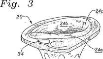
三尖弁20は、図1における平面図において見出され、そして輪22および輪により規定される流口(flow orifice)へと内側に延びる3つのリーフレット24a、24b、24c(それぞれ、中隔、前方、および後方)を含む。腱索26は、これらのRV中に配置された乳頭筋にリーフレットを接続して、これらのリーフレットの動きを制御する。三尖弁輪22は、弁の基部の卵型の繊維状環であり、これは、僧坊弁の輪ほど突出していないが、周がわずかに大きい。中隔リーフレット24aは、線維三角への取りつけ部位である、心臓内の繊維状の「骨格」構造である。コッホ三角30およびトダーロ腱32は、三尖弁修復手順の間、解剖学的ランドマークを提供する。房室(AV)結節34は、結節組織のセクションであり、このセクションは、最初に、洞房結節からの心臓のインパルスを遅延させてこの房が収縮してそれらの内容物を枯渇させることを可能にし、そして房室束への心臓のインパルスを中継する。正常な心臓のリズムにおいて、洞房結節は、電気的インパルスを発生させ、このインパルスは、右心房筋および左心房筋を介して移動し、電気的変化をおこす(これは、p−波により心電図(ECG)上で現れる))。次いで、電気的インパルスは、より遅いペースで導電するAV結節34の特定された組織を通ってさらに移動を続ける。これは、心室が刺激される前に休止(PR間隔)させる。当然、外科医は、AV結節34に近すぎるかまたはその中に縫合糸を位置させることを避けなくてはならない。Cリングにより、外科医は、AV結節34に隣接して環の中を切断をすることができ、従って、その位置で縫合する必要性がないので、この環は、三尖弁の修復のための良い選択である。 The
多数の設計が現在利用可能であるかまたは過去に提案されているが、三尖弁輪の実際の形状によりぴったりと一致する三尖弁輪についての必要性が存在する。 Although many designs are currently available or have been proposed in the past, there is a need for a tricuspid annulus that more closely matches the actual shape of the tricuspid annulus.
(発明の要旨)
本発明は、軸の周りでほぼ構成され、2つの自由端を規定するように不連続である環本体を備える弁形成リングを提供する。この環本体は、三次元経路に沿った弛緩構成を有し、その結果、これらの自由端は、環本体の中間点を通る輪の参照平面から軸方向にオフセットである。好ましい実施形態において、2つの自由端は、約2〜15mmの間で軸方向にオフセットである。弁形成リングは、特に、三尖弁輪を強化するように適合されており、そしてまた、一方の自由端で終結する曲線状の前方側部、他方の自由端で終結する曲線状の後方側部および前方側部と後方側部との間の相対的に直線状の中隔側部を有する。後方側部は、前方側部より短くそしてより小さい曲率半径を有する。(Summary of the Invention)
The present invention provides an annuloplasty ring comprising an annulus body that is generally configured about an axis and is discontinuous to define two free ends. The ring body has a relaxed configuration along a three-dimensional path so that these free ends are axially offset from the reference plane of the ring through the midpoint of the ring body. In a preferred embodiment, the two free ends are axially offset between about 2-15 mm. The annuloplasty ring is specifically adapted to reinforce the tricuspid annulus, and also has a curved front side that terminates at one free end, a curved rear side that terminates at the other free end And a relatively straight septum side between the front side and the rear side. The rear side is shorter and has a smaller radius of curvature than the front side.
本発明の1つの局面に従って、この環本体は、弾性材料の複数バンドの内部構造支持体を備える。低摩擦材料が、各々の2つの隣接するバンドの間に挿入されて、その間の移動を容易にし得る。複数のバンドが、柔軟な材料(好ましくは成形されたシリコーン)のマトリクス中に包埋され得る。1つの実施形態において、柔軟な材料のマトリクス中に包埋された、2つの同軸に配置されたバンドが存在する。半径方向に延びる軸の周りの湾曲を容易にするために、これらの弾性材料の複数のバンドの各々が、その軸方向の寸法より相対的に広い半径方向の寸法を有し得る。 According to one aspect of the invention, the ring body comprises a multi-band internal structural support of elastic material. A low friction material may be inserted between each two adjacent bands to facilitate movement therebetween. Multiple bands can be embedded in a matrix of flexible material (preferably molded silicone). In one embodiment, there are two coaxially arranged bands embedded in a matrix of flexible material. In order to facilitate curvature about a radially extending axis, each of the plurality of bands of elastic material may have a radial dimension that is relatively wider than its axial dimension.
本発明の別の局面は、ほぼ中心軸の周りに構成され、2つの自由端を規定するように不連続である三次元環本体を備える弁形成リングであり、ここでこの環本体は、この環本体を、その2つの自由端での湾曲において、その中間点での湾曲より可撓性にするような構成を有する。 Another aspect of the present invention is an annuloplasty ring comprising a three-dimensional ring body that is configured about a central axis and is discontinuous to define two free ends, wherein the ring body is The ring body is configured to be more flexible in bending at its two free ends than bending at its midpoint.
この弁形成リング本体は、内部構造支持体を備え得、この内部構造支持体は、2つの自由端、これらの自由端の一方で終結する曲線状の前方側部、これらの自由端の他方で終結する直線状の中隔側部、および前方側部と中隔側部との間に延びる曲線状の後方側部を有し、ここで、後方側部の大部分は、ほぼこの軸に垂直な平面内にある。2つの自由端は、望ましくは、両方、この平面から同じ方向に軸方向にオフセットである。また、構造支持体は、その長さに沿って変化する断面を有し得る。例えば、断面は、後方側部において一部C型であり得、そしてなお2つの自由端は、矩形である。 The annuloplasty ring body may comprise an internal structural support, the internal structural support being two free ends, a curved forward side terminating at one of these free ends, at the other of these free ends. It has a straight septal side that terminates and a curved rear side that extends between the front side and the septal side, where the majority of the rear side is approximately perpendicular to this axis. In a flat plane. The two free ends are preferably both offset axially in the same direction from this plane. The structural support can also have a cross section that varies along its length. For example, the cross-section can be partially C-shaped at the rear side and still the two free ends are rectangular.
本発明のさらなる局面に従うと、この環本体は、柔軟なマトリクスで囲まれた内部構造支持体バンドを備え得、ここで、このマトリクスは、このバンドを囲む管状の内側部分および移植縫合糸が通過し得る外部フランジを備える。外部フランジは、その外部表面上が凸面であるように湾曲され得る。好ましくは、この外部フランジは、複数の円周状に間隔の空いた半径方向の壁で、セル構造を作製するように、その内側管状部分に接続される。 According to a further aspect of the invention, the annulus body may comprise an internal structural support band surrounded by a flexible matrix, wherein the matrix passes through the tubular inner portion surrounding the band and the graft suture. A possible external flange. The outer flange can be curved so that its outer surface is convex. Preferably, the outer flange is connected to its inner tubular portion so as to create a cell structure with a plurality of circumferentially spaced radial walls.
本発明のさらなる局面は、ほぼ中心軸の周りに構成され、2つの自由端を規定するように不連続である環本体を備える弁形成リングを提供する。この環本体は、この環本体を、中心軸から半径方向に延びる軸の周りでの湾曲において、中心軸自体の周りでの湾曲より可撓性であるようにする構造を有する。この環本体は、弾性材料の複数のバンドの内部構造支持体を備え得る。低摩擦材料が、各々の2つの隣接するバンドの間に挿入され得る。複数のバンドが、柔軟な材料(好ましくはシリコーン)のマトリクス中に包埋され得る。柔軟な材料のマトリクス中に包埋された、2つの同軸に配置されたバンドが存在し得る。望ましくは、これらの弾性材料の複数のバンドの各々が、その軸方向の寸法より相対的に広い半径方向の寸法を有し得る。 A further aspect of the present invention provides an annuloplasty ring comprising an annulus body that is configured about a central axis and that is discontinuous to define two free ends. The ring body has a structure that makes the ring body more flexible in bending around an axis extending radially from the central axis than bending around the central axis itself. The ring body may comprise an internal structural support of a plurality of bands of elastic material. A low friction material can be inserted between each two adjacent bands. Multiple bands can be embedded in a matrix of flexible material (preferably silicone). There may be two coaxially arranged bands embedded in a matrix of flexible material. Desirably, each of the plurality of bands of elastic material may have a radial dimension that is relatively wider than its axial dimension.
本発明のさらなる局面において、弁形成リングテンプレートが提供される。このテンプレートは、軸の周りに構成され、そして2つの自由端を規定するように不連続である周辺の取り付け環を有する剛性の本体を有する。この取り付け環は、これらの自由端が軸方向にオフセットであるように三次元の経路に沿っている。このテンプレートは、中央プラットフォームを備え得、周辺の取り付け環は、複数のほぼ半径方向に延びるスポークを介してこの中央プラットフォームに取りつけられる。ハンドル受容ハブは、ほぼ中央プラットフォームから延び得る。望ましくは、周辺の取り付け環は、軸の周りで、円周上に約四分の三、延びる。 In a further aspect of the invention, an annuloplasty ring template is provided. The template is constructed around an axis and has a rigid body with a peripheral mounting ring that is discontinuous to define two free ends. The mounting ring is along a three-dimensional path so that these free ends are offset in the axial direction. The template may comprise a central platform, with a peripheral mounting ring attached to the central platform via a plurality of substantially radially extending spokes. The handle receiving hub may extend from approximately the central platform. Desirably, the peripheral mounting ring extends about a quarter of the circumference around the axis.
好ましい実施形態において、テンプレートの周辺の取り付け環は、その中に弁形成リングを受容するための半径方向外側の溝を規定する。このテンプレートは、周辺の取り付け環上に提供された複数のカッティングガイドをさらに備え得る。この取り付け環における一対の貫通する穴は、一本の縫合糸が、この取り付け環の外側に配置された弁形成リングを通ってかまたはその周りを通り、これらの穴の1つを通り、カッティングガイド上を通り、他の穴を通り、そして弁形成リングに戻るように延び得るように、各々のカッティングガイドのいずれかの側部に提供される。各々のカッティングガイドは、一対の交差するスロットを備え得、これらのスロットのうち一方は、他方より浅く、そしてこれらの貫通する穴の間に延びる縫合糸を受容するように配置される。より深いスロットは、鋭利な器具がこのカッティングガイドで縫合糸を切断するように延び得る空間を提供する。 In a preferred embodiment, the mounting ring around the template defines a radially outer groove for receiving the annuloplasty ring therein. The template may further comprise a plurality of cutting guides provided on the peripheral mounting ring. A pair of through-holes in the mounting ring allows a single suture to pass through or around the annuloplasty ring located on the outside of the mounting ring, through one of these holes, cutting Provided on either side of each cutting guide so that it can extend over the guide, through the other holes, and back to the annuloplasty ring. Each cutting guide may comprise a pair of intersecting slots, one of these slots being shallower than the other and arranged to receive a suture extending between these penetrating holes. The deeper slot provides a space where a sharp instrument can extend to cut the suture with this cutting guide.
本発明の特徴および利点のさらなる理解は、本明細書および図面の残りの部分を参照することにより明らかになる。 A further understanding of the features and advantages of the present invention will become apparent by reference to the remaining portions of the specification and drawings.
(好ましい実施形態の説明)
本発明は、非平面または三次元(3D)の弁形成リングを提供し、この環は、3Dの輪に一致するような形状である。いくつかの研究は、三尖弁が、そのような非平面輪を有し、従って、本発明は、特に、その弁の修復に適することを示す。当然他の弁が、何人かの患者において3Dの輪を有し得、そして本発明の弁形成リングもまた、外科医により所望される場合、これらの位置での有用性を有し得る。当然、全ての弁形成リングは断面の厚さを有するので、これらの環は、ある程度、三次元である。本発明の文脈において、非平面または三次元の弁形成リングは、三次元形状を仮定する公称断面中心線を有し、言いかえれば、単一平面上に乗らない。同様に、本発明の例示的な環、および本明細書中で体現される特徴からの利益を得ることができるほかの形状は、非環状の周辺形状を有するが、軸を有することが示されている。例示される環、および他の非環状または非平面状の環に対する参照において用語「軸」とは、平面図において見た場合に環の領域の中心を通過する、環を通る線を言う。この「軸」はまた、環が移植された場合、弁の穴の中(従って、環の中)の血流の想像線としてみなされ得る。(Description of Preferred Embodiment)
The present invention provides a non-planar or three-dimensional (3D) annuloplasty ring that is shaped to match a 3D ring. Some studies indicate that tricuspid valves have such a non-planar ring and therefore the present invention is particularly suitable for repair of the valve. Of course, other valves may have a 3D annulus in some patients, and the annuloplasty ring of the present invention may also have utility in these positions if desired by the surgeon. Of course, since all annuloplasty rings have a cross-sectional thickness, these rings are to some extent three dimensional. In the context of the present invention, a non-planar or three-dimensional annuloplasty ring has a nominal cross-sectional centerline that assumes a three-dimensional shape, in other words, does not ride on a single plane. Similarly, exemplary rings of the present invention, and other shapes that can benefit from the features embodied herein, are shown to have a non-annular peripheral shape but have an axis. ing. The term “axis” in reference to the exemplified rings and other non-annular or non-planar rings refers to a line through the ring that passes through the center of the region of the ring when viewed in plan view. This "axis" can also be considered as an imaginary line of blood flow in the valve hole (and thus in the ring) when the ring is implanted.
本明細書中の実施形態のいずれか1つの種々の構造的詳細は、明白に記述されない場合でさえ、別の実施形態に移され得ることが理解されるべきである。例えば、図8A〜8Dにおいて見出される内部環構造支持体は、他の場所に記載されるように、シリコーンスリーブおよび外部ファブリックカバーを有する環において用いられ得る。また、図5〜7に見出されるテンプレート90または110は、図8A〜図8Dにおいて見出される内部環構造支持体を用いて構築された環に一致し、そしてそれを保持するように適合され得る。 It should be understood that various structural details of any one of the embodiments herein may be transferred to another embodiment even if not explicitly described. For example, the inner ring structure support found in FIGS. 8A-8D can be used in rings with a silicone sleeve and an outer fabric cover, as described elsewhere. Also, the
過去、多数の環のデザインがあるにも関らず、有効に三尖弁の形状に適合したものはなかった。従来のC型環(すなわち、周辺の当たりに連続性のない点を(break in continuity)を有する環)が平面上に形成される。移植される場合、平面の環は、その相対的な剛性に起因して、その環自体の形状に対して、非平面輪を一致させる傾向にある。不幸なことに、これは、「修復される」弁の最適な能力を妨害し得る。 In the past, despite the many ring designs, none of them effectively matched the shape of the tricuspid valve. A conventional C-shaped ring (ie, a ring having break in continuity around the periphery) is formed on the plane. When implanted, the planar ring tends to match the non-planar ring to the shape of the ring itself due to its relative stiffness. Unfortunately, this can interfere with the optimal ability of the “repaired” valve.
図2は、ほぼ軸44の周りに構成され、2つの自由端46a、46bを規定するように不連続である環本体42を有する本発明の例示的な弁形成リング40を例示する。図3は、遠近法での三尖弁20を示し、そして図4は、移植されているかそうでなければ三尖弁20に固定された後の平面図における弁形成リング40を示す。図4において見出されるように、平面図において見る場合、弁形成リング40の本体42は、相対的に直線状の中隔側部50a、曲線状後方側部50b、および曲線状前方側部50cを規定する。後方側部50bは、前方側部50cより短く、そしてより小さい曲率半径を有する。 FIG. 2 illustrates an
再び、図2における軸44は、移植された場合、この環の中心にあるか、または環40を通る血流の軸に沿って存在し、そして上方向および下方向は、図で見られるような方向であることが理解される。環40は、血液が下方向に流れるように三尖弁輪中に移植されるように設計される。 Again,
図2は、2つの自由端46a、46bの例示的な軸方向のオフセットを示す。ラジアル線が各々の自由端46a、46bから中心軸44に示される。これらのラジアル線と軸44との交点の間の距離Aは、軸方向のオフセットを表す。距離Aは、患者に依存して変化し得るが、代表的には、約2.0mm〜約15.0mmの間である。この実施形態において、曲線状前方側部50cは、自由端46aまでの全てでほぼ平面内にある。従って、第二の自由端46bが、この環およびホストの輪についての輪状の参照平面をほぼ規定する前方側部50cの主要な部分の下に下がるので、ついで、それは、第一の自由端46aから軸方向にオフセットである。しかし、第一の自由端46aは、環状参照平面内にないかもしれず、第二の自由端46bと同じ面に下がり得る。自由端46a、46bのいずれかは、環状参照平面の軸方向上側にさえあり得る。簡潔には、環40は、ネイティブの三尖弁輪に一致するように三次元的に設計され、そして当業者は、可能な変更の数を認識する。 FIG. 2 shows an exemplary axial offset of the two
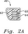
弁形成リング40が、従来技術において規定された多数の方法で構築され得るが、1つの特に有用な構造は、柔軟なコア材料およびファブリックカバーにより囲まれたいくつかの相対的に剛性でありなお弾性の内部構造支持体を備える。例えば、図2Aに見出されるように、弁形成リング40は、縫合透過性コア材料62(例えば、シリコーン)により囲まれ、外部ファブリックカバー64を有する、相対的に剛性でありなお弾性の材料(例えば、Elgiloy)の複数バンドの内部骨格60を備え得る。複数バンド60は、より容易に互いに対して曲がり得るように、プラスチックまたは他の相対的に低摩擦材料(例えば、TEFLON)により分離され得る。複数バンド60(これは、環40の可撓性を制限する)が、軸44に対してほぼ垂直に整列され、従って、この環は、少なくとも軸の周りでの湾曲において可撓性であることが当業者に注目される。望ましくは、本発明の環40は、中心軸44からのラジアル線に沿った軸の周りでの湾曲においてより可撓性である。すなわち、例えば、自由端46a、46bは、互いに対する方向または互いから離れる方向よりも軸に対して平行に上方向および下方向に、容易に曲げられる。図2C〜図2Eに見出されるように、この可撓性の方向付けを達成するための多数の方法が存在する。 Although the
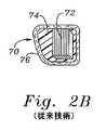
対照的に、図2Bは、外側のファブリックカバー76を有する縫合透過性のコア材料74(例えば、シリコーン)により囲まれた相対的に剛性な材料(例えば、Elgiloy)の複数バンドの内部骨格72を有する従来技術の環70の断面を示す。そのような従来技術のデバイスにおいて、バンド60は、軸44に沿ってかまたはそれに平行に方向付けられ、従って、中心軸の周りでの湾曲においてより可撓性である。 In contrast, FIG. 2B shows a multi-band
図2Cは、より柔軟なマトリクス80(例えば、シリコーン)中に包埋された複数の内部バンド78を有する本発明の代替的な環の断面を示す。前述のように、望ましくは、バンド78は、マトリクス80より剛性であり、そして移植された場合、この輪に構造的支持を提供する。バンド78は、本発明の環の好ましい可撓性特性を提供するように、軸方向の寸法が薄くかつ半径方向に広い。バンド78は、前述の可撓性を増強するように、その間のマトリクス80で間隔が空いていることが示される。 FIG. 2C shows an alternative ring cross section of the present invention having a plurality of
図2Dは、柔軟な材料のマトリクス82中に包埋された2つの同軸に配置された構造バンド81が存在するさらなる実施形態を例示する。バンド81は、これらのそれぞれの断面が四角または円のいずれである場合でも、上で説明したように、一緒になって、この環の所望の可撓性特性を作り出す。しかし、見出されるように、好ましくは、バンド81は、軸方向の寸法より大きな半径を有する(このことは、半径方向軸の周りの環の可撓性に寄与する)。 FIG. 2D illustrates a further embodiment in which there are two coaxially arranged
図2Eは、柔軟なマトリクス84により囲まれた円周上の強化バンド83を有する環の断面を示す。マトリクス84の管状の内側部分は、バンド83を囲み、一方、外壁フランジ85は、移植縫合糸が通過し得るさらなる材料を提供する。好ましい実施形態において、フランジ85は、その外部表面上が凸形であるように湾曲しており、そして複数の円周上に間隔の空いた半径方向の壁86を有する内部管状部分に結合されている。従って、一連の円周上のセル87が、壁86の間に作製される。マトリクス84のセル状構造は、このマトリクス84を、柔軟かつ圧縮性のあるものにし、このことは、非常にでこぼこした環に対するこの輪の一致を容易にする。ファブリックカバー(示さず)もまた用いられ得る。 FIG. 2E shows a cross-section of an annulus with a circumferential reinforcing
図2および図3を再び参照して、三次元形状の弁形成リング40が、三尖弁輪22の形状にほぼ対応して見出される。第一の自由端46aは、中隔リーフレット24aに隣接する領域を、AV結節34の前方側部に対して位置決めする。第二の自由端46bは、中隔リーフレット24aに隣接する領域をAV結節34の後方側部に対して位置決めする。第二の自由端46bは、それぞれの解剖学的取り付け領域がそうであるように、第一の自由端46aに対して軸方向にオフセットである。従って、弁形成リング40は、輪22の3−D形状にぴったり一致し、そして環がその輪に取り付けられた場合、最小限の組織の歪みが生じる。さらに、自由端46a、46bは、軸44に対して平行である弧に沿って、互いに対して容易に曲げられ得るので、環40の方向付けられた可撓性は、環と組織との間の3−D形状の適合を容易にする。 Referring again to FIGS. 2 and 3, a three-dimensional
当業者は、他の取りつけ手段が存在することを理解するが、複数の縫合糸88を用いて輪22中に移植された弁形成リング40が図4に見出される。縫合糸88は、環本体42の周りに均一に分配され、そして最小限の表面粗さを表すように締め付けられ、そしてそこに血栓が形成される機会を減少する。再び、自由端46a、46bは、AV結節34のいずれかの側部上に示され、これらは、感受性の伝導系を損傷する危険性を最小限にする。 Those skilled in the art will appreciate that other attachment means exist, but an
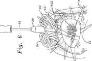
好ましい送達テンプレートおよび方法がまた、本発明の三次元弁形成リング40を提供される。図5および図6に関して、環40は、テンプレート90に取り外し可能に固定され、これは、次いで、送達ハンドル92の遠位端に保持されることが見出される。テンプレート90は、環40が移植される間、その有利な形状を維持する、環40のための縫合プラットフォームを提供する。これに関して、テンプレート90は、環40の軸44と一致する軸の周りにほぼ構成された周辺の取り付け環94を備える。この周囲の取り付け環94は、2つの自由端96a、96bを規定するように不連続であり、そしてこれらの自由端が軸方向にオフセットであるような三次元経路にほぼ沿っている。望ましくは、この周辺の取り付け環94の三次元経路は、弁形成リング40の三次元経路と同一である。縫合糸(示さず)または他の類似の好都合な取り外し可能な手段は、テンプレート90に環40を固定して、図5に見出されるようなアセンブリを形成する。ハンドル92のハブ98は、縫合糸または迅速取り外し(quick−release)クリップ等を用いてテンプレートに取り外し可能に取り付けられ得、その結果、このハンドルは、輪のより良好な視界のために移植の間、取り外され得る。 Preferred delivery templates and methods are also provided for the three-
図6は、中断された縫合移植手順における工程を示す。環22を露出した後、外科医は、複数の個々の縫合糸100を、輪22の周りで固定し、その位置においてこれらの縫合糸が、環40の周りに配置される。次いで、各々の縫合糸100の自由端は、102に見出されるように環40の縫合透過性の外側部分における対応する位置を通過される。全ての縫合糸100が環40に予め通された後、外科医は、ハンドル92を用いて環を縫合糸のアレイの下、そして環22中の位置に操作する。例示されていない次の工程は、各々の縫合糸を環40に密着して縫合し、これらを、図4に見出されるように固定することを含む。再び、ハンドル92が、この操作のためにテンプレート90から取り外され得る。最後に、テンプレート90が、環40から取り外され、そして操作部位から任意の取り付けられた縫合糸が取り外される。 FIG. 6 shows the steps in an interrupted suture implantation procedure. After exposing the
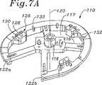
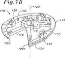
図7A〜図7Cは、本発明の環40の移植における使用のための例示的テンプレート110の複数の斜視図である。テンプレート110は、複数のスポーク116を介して中央プラットフォーム114に結合された周囲の取り付け環112を備える。テンプレート110は、種々の材料から構成され得、生体適合性プラスチックが好ましい。ウインドウ117は、移植部位のより良好な視界のためにスポーク116の間に存在する。ハンドル受容ハブ118は、プラットフォーム114から上方向に突出し、そしてテンプレート110の中心軸120をほぼ規定する。取り付け環112は、軸120の周りに約四分の三、延び、そして2つの軸方向に間隔の空いた端部122a、122bにおいて終結する。 7A-7C are multiple perspective views of an
好ましい実施形態において、取り付け環112は、半径方向外側に開くチャネルまたは溝124を備え、これは、環40とほぼ同じ曲線を有するようにサイズ決めされ、従って、環40をテンプレート90の周りの適切な場所にぴったりと保持させる。溝124は、環の大部分がそこから外側に突出して、輪に対する露出およびそれに対する取りつけを容易にするように浅い。 In a preferred embodiment, the mounting
複数の(好ましくは3つの)カッティングガイド126が、取り付け環112から、その周辺に規則的な間隔で軸方向上側に突出する。カッティングガイド126の各々は、第一の相対的に深いスロット128および第一のスロットと交差する第二のより浅いスロット130を備える。望ましくは、縫合糸(示さず)は、環40を、テンプレートに固定し、そして容易に切断可能なように、カッティングガイド126を超えて延びる。取り付け環112において溝124の中に開いている複数の通路132は、環本体42から取り付け環を通り、カッティングガイド126までの、縫合糸の直接的な通過を可能にする。図7Aに最もよく見出されるように、各々のカッティングガイド126のいずれかの側部上に2つのそのような通路132が存在する。望ましくは、通路132は、取り付け環112の上部表面からの直線状の穴であり、この穴は、交差し、従って凹型溝124に対して開いている。 A plurality of (preferably three) cutting guides 126 protrude from the mounting
取り付け環112の全体形状は、上記のように、三次元であり、2つの自由端122a、122bは、軸方向に間隔が空いている。この三次元構造は、緩やかな螺旋でも、特定の患者もしくは患者の代表的なサンプルにより規定される他の類似の形状でもよい。例示的な実施形態において、そして図7Cにおいて最もよく見出されるように、この取り付け環112の大部分は、平面内にあり、第二の自由端122bで終結する一方の側部は、第一の自由端122aから軸方向に間隔が空けられるように緩やかな曲線または螺旋に形成される。取り付け環112の一部が取り付け環のらせんセグメントに沿って延びる中隔リーフレットに隣接して存在するように、この弁形成リングが取り付け環112上に構成される(図4の24aおよび50aを参照のこと)。一般的に、多くの患者が、前方側部および後方側部の周りに相対的に平面状の三尖弁輪を有するが、扁平の中隔側部の周りには有さないと考えられている。従って、取り付け環112の形状は、推定の解剖学的輪郭を模倣し、従って、この環は、輪を過度に歪めることなく適切な位置に縫合され得る。 The overall shape of the mounting
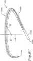
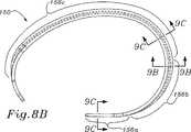
図8A〜8Dは、本発明の三尖弁形成リングのための例示的な内部構造支持体150を例示する。構造支持体150は、最終的には、上記のように、1つ以上の外側の可撓性層で覆われ、従って、最終的な環本体は、支持体の形状を仮定する。構造支持体150は、相対的に剛性の材料であり、なお弾性の材料(例えば、Elgiloy)から作製され得る。 8A-8D illustrate an exemplary
図8Bにおいて見出されるように平面図において見た場合、構造支持体150は、一方の自由端154bで終結する相対的に直線状中隔側部156a、曲線状後方側部156b、および他方の自由端154aで終結する曲線状前方側部156cを規定する。後方側部156bは、他の2つの側部の間にある。前述の実施形態におけるように、後方側部156bは、前方側部156cより短く、そして前方側部156cより小さい曲率半径を有する。 When viewed in plan view as seen in FIG. 8B, the
構造支持体150は、軸152の周りにほぼ構成されており、そして2つの自由端154a、154bを規定するように不連続である。構造支持体150の大部分は、軸152に垂直な輪状参照平面151の中にほぼあり(図8D)、そして2つの自由端154a、154bは、その平面からオフセットであるように、その平面から湾曲する。輪状参照平面151は、三尖弁輪の高さで軸152に垂直である平面として規定される。次いで、この高さは、図面において、(下記のように)前方側部156cの中間点、またはそのより大きな断面部分の中間点により表される。図8Cは、前方側部56cにおける中間点Mを例示し、この点は、ホストの輪の名目上の高さを表す。この軸152に対する垂線は、参照点Rで接する。従って、参照平面は、点Rを通り、軸52に対して垂直である。
従って、図8Dに最もよく見出されるように、2つの自由端154a、154bは、参照軸151から同じ方向で、そして互いに、軸方向にオフセットである。当然、この環は、なお三次元である(すなわち、この環は、平面状でない)が、自由端154a、154bは、示されるように、互いから、軸方向にオフセットである必要はない。例えば、これらの自由端154a、154bの一方または両方は、参照平面151の上に上方に湾曲さえし得る。特定の三次元の構成は、三尖弁輪の天然の形状に適合するか、または可能な限り少なくともその形状に近づくようにモデル化され、従って、三尖弁輪の当業者は、種々の形態が可能であることを理解する。 Thus, as best seen in FIG. 8D, the two
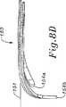
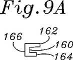
図8Bおよび図9A〜図9Cに関して、少なくとも前方側部156cのほとんどに沿った、構造支持体150の断面形状が、自由端154a、154bでの湾曲においてより可撓性を有するように設計される。図9Aは、後方側部156cを通る断面であり、そしてこれは、上部ウェブ162と下部ウェブ164との間(両方が内側基部166から延びる)に形成される外側に面する溝160を有するほぼC型の断面を示す。上部ウェブ162は、下部ウェブ164より半径方向にわずかに遠く延びる。 8B and 9A-9C, the cross-sectional shape of the
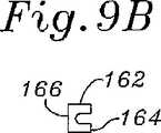
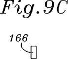
構造支持体150の断面形状は、中間点Mから自由端154a、154bまで、その長さに沿って変化する。前方側部156cの中間点での断面と2つの自由端154a、154bでの断面との間の移行は、ゆるやかであり、そして図9A〜9Cにおいて反映されている。ウェブ162、164は、図9Cにおいて見出されるように、半径方向の寸法において徐々に無くなり、残るのは、矩形の基部166だけである。両方の自由端154a、154bで、半径方向の寸法は、軸方向より短いので、端部は、中心軸152の周りでの湾曲においてより可撓性である。図8A〜8Dにおいて見出される内側環構造支持体の特性は、他の構造(例えば、上記のような、複数の同軸のバンド)と共に与えられ得ることが記述されるべきである。 The cross-sectional shape of the
本発明の好ましい実施形態の完全な説明が前述されたが、種々の代替物、改変、および等価物が用いられ得る。さらに、特定の他の改変が添付の特許請求の範囲内で実施され得ることが明らかである。 While a complete description of the preferred embodiments of the present invention has been described above, various alternatives, modifications, and equivalents may be used. Furthermore, it will be apparent that certain other modifications may be practiced within the scope of the appended claims.
Claims (29)
Translated fromJapanese該前方側部は、該自由端が、該環本体の中間点を通る輪の参照平面から軸方向にオフセットであるような三次元経路に従う構成を有し、該前方側部は、該三尖弁輪の公称高さを示し、該輪の参照平面は、該三尖弁輪の該公称高さの軸に垂直であり、
該2つの自由端が互いに軸方向にオフセットであり、該軸方向のオフセットは、該端の各々から該軸への半径方向の線の交点の間の距離である、
弁形成リング。Anannuloplasty ring having an annulus body configured about an axis and discontinuous to define two free ends, wherein theannulus is adapted to reinforce the tricuspid annulus And a curvilinear front side terminating at one of the free ends, a relatively straight septal side terminating at the other free end, and between the front side and the septal side A curved rear side extending to the rear side, the rear side being shorter than the front side and having a smaller radius of curvature than the front side,
Said front side, said free end,have aconfiguration which follows from the reference plane of the wheel passing through the midpoint of the ring body in a three-dimensional path as axially areoffset, said front side portion, the three Indicates the nominal height of the leaflet, the reference plane of the ring is perpendicular to the axis of the nominal height of the tricuspid valve ring;
The two free ends are axially offset from each other, the axial offset being the distance between the intersection of radial lines from each of the ends to the axis;
Annuloplasty ring.
該環本体は、該環本体を、該2つの自由端での湾曲においてその中間点より可撓性にする構造を有し、該2つの自由端は、該三尖弁輪の公称高さを示す該前方側部の中間点を通じた輪の参照平面から軸方向にオフセットであり、該輪の参照平面は、該三尖弁輪の該公称高さの軸に垂直であり、
該2つの自由端が、両方とも、前記環本体の中間点を通る輪の参照平面から軸方向にオフセットであり、該2つの自由端が互いに軸方向にオフセットであり、該軸方向のオフセットは、該端の各々から該軸への半径方向の線の交点の間の距離である、
弁形成リング。Disposed about the substantially central axis, and a annuloplasty ring with a discontinuity in a three-dimensional ring body so as to define two free ends, wherein thering body has two free ends An inner structural support, a curvilinear front side terminating at one of the free ends, a relatively linear septal side terminating at the other free end, and the front and septal sides; A curved rear side extending between, wherein a majority of the rear side is in a plane substantially perpendicular to the axis.
Ring body, the ring body,have a structure that flexible than its midpoint in the curved at the two free ends,the two free ends, the nominal height of the tricuspid annulus Is axially offset from the reference plane of the wheel through the midpoint of the front side shown, the reference plane of the wheel being perpendicular to the nominal height axis of the tricuspid valve annulus,
The two free ends are both axially offset from the reference plane of the ring passing through the midpoint of the ring body, the two free ends are axially offset from each other, and the axial offset is , The distance between the intersection of radial lines from each of the ends to the axis,
Annuloplasty ring.
Applications Claiming Priority (3)
| Application Number | Priority Date | Filing Date | Title |
|---|---|---|---|
| US09/941,406US6749630B2 (en) | 2001-08-28 | 2001-08-28 | Tricuspid ring and template |
| US10/139,070US6908482B2 (en) | 2001-08-28 | 2002-05-03 | Three-dimensional annuloplasty ring and template |
| PCT/US2002/027506WO2003020178A1 (en) | 2001-08-28 | 2002-08-28 | Three-dimensional annuloplasty ring and template |
Publications (2)
| Publication Number | Publication Date |
|---|---|
| JP2005501605A JP2005501605A (en) | 2005-01-20 |
| JP4291142B2true JP4291142B2 (en) | 2009-07-08 |
Family
ID=26836832
Family Applications (1)
| Application Number | Title | Priority Date | Filing Date |
|---|---|---|---|
| JP2003524492AExpired - LifetimeJP4291142B2 (en) | 2001-08-28 | 2002-08-28 | 3D annuloplasty rings and templates |
Country Status (7)
| Country | Link |
|---|---|
| US (5) | US6908482B2 (en) |
| EP (1) | EP1420723B1 (en) |
| JP (1) | JP4291142B2 (en) |
| AT (1) | ATE419809T1 (en) |
| CA (1) | CA2456838C (en) |
| DE (1) | DE60230771D1 (en) |
| WO (1) | WO2003020178A1 (en) |
Families Citing this family (192)
| Publication number | Priority date | Publication date | Assignee | Title |
|---|---|---|---|---|
| US6955689B2 (en)* | 2001-03-15 | 2005-10-18 | Medtronic, Inc. | Annuloplasty band and method |
| US6786924B2 (en)* | 2001-03-15 | 2004-09-07 | Medtronic, Inc. | Annuloplasty band and method |
| US6800090B2 (en)* | 2001-05-14 | 2004-10-05 | Cardiac Dimensions, Inc. | Mitral valve therapy device, system and method |
| US7935145B2 (en) | 2001-05-17 | 2011-05-03 | Edwards Lifesciences Corporation | Annuloplasty ring for ischemic mitral valve insuffuciency |
| ITMI20011012A1 (en) | 2001-05-17 | 2002-11-17 | Ottavio Alfieri | ANNULAR PROSTHESIS FOR MITRAL VALVE |
| US7367991B2 (en)* | 2001-08-28 | 2008-05-06 | Edwards Lifesciences Corporation | Conformal tricuspid annuloplasty ring and template |
| US6908482B2 (en)* | 2001-08-28 | 2005-06-21 | Edwards Lifesciences Corporation | Three-dimensional annuloplasty ring and template |
| US7635387B2 (en)* | 2001-11-01 | 2009-12-22 | Cardiac Dimensions, Inc. | Adjustable height focal tissue deflector |
| US6824562B2 (en) | 2002-05-08 | 2004-11-30 | Cardiac Dimensions, Inc. | Body lumen device anchor, device and assembly |
| US6805710B2 (en)* | 2001-11-13 | 2004-10-19 | Edwards Lifesciences Corporation | Mitral valve annuloplasty ring for molding left ventricle geometry |
| US6976995B2 (en) | 2002-01-30 | 2005-12-20 | Cardiac Dimensions, Inc. | Fixed length anchor and pull mitral valve device and method |
| US7179282B2 (en)* | 2001-12-05 | 2007-02-20 | Cardiac Dimensions, Inc. | Device and method for modifying the shape of a body organ |
| US20050209690A1 (en)* | 2002-01-30 | 2005-09-22 | Mathis Mark L | Body lumen shaping device with cardiac leads |
| US6719786B2 (en)* | 2002-03-18 | 2004-04-13 | Medtronic, Inc. | Flexible annuloplasty prosthesis and holder |
| US7118595B2 (en)* | 2002-03-18 | 2006-10-10 | Medtronic, Inc. | Flexible annuloplasty prosthesis and holder |
| DE60234675D1 (en)* | 2002-03-27 | 2010-01-21 | Sorin Biomedica Emodialisi S R | Anuloplasty prosthesis with a pierced component |
| CA2877641C (en) | 2002-05-08 | 2017-01-17 | Cardiac Dimensions Pty. Ltd. | Device and method for modifying the shape of a body organ |
| EP1531762B1 (en)* | 2002-08-29 | 2010-04-14 | St. Jude Medical, Cardiology Division, Inc. | Implantable devices for controlling the internal circumference of an anatomic orifice or lumen |
| US8758372B2 (en)* | 2002-08-29 | 2014-06-24 | St. Jude Medical, Cardiology Division, Inc. | Implantable devices for controlling the size and shape of an anatomical structure or lumen |
| US7316708B2 (en) | 2002-12-05 | 2008-01-08 | Cardiac Dimensions, Inc. | Medical device delivery system |
| DE10301023A1 (en)* | 2003-01-13 | 2004-07-22 | Medos Medizintechnik Ag | Implant, in particular ring for heart valve, designed in curved and asymmetric shape |
| US20040158321A1 (en)* | 2003-02-12 | 2004-08-12 | Cardiac Dimensions, Inc. | Method of implanting a mitral valve therapy device |
| US20040220654A1 (en) | 2003-05-02 | 2004-11-04 | Cardiac Dimensions, Inc. | Device and method for modifying the shape of a body organ |
| US9526616B2 (en) | 2003-12-19 | 2016-12-27 | Cardiac Dimensions Pty. Ltd. | Mitral valve annuloplasty device with twisted anchor |
| US7794496B2 (en) | 2003-12-19 | 2010-09-14 | Cardiac Dimensions, Inc. | Tissue shaping device with integral connector and crimp |
| US20050137450A1 (en)* | 2003-12-19 | 2005-06-23 | Cardiac Dimensions, Inc., A Washington Corporation | Tapered connector for tissue shaping device |
| US20070073387A1 (en)* | 2004-02-27 | 2007-03-29 | Forster David C | Prosthetic Heart Valves, Support Structures And Systems And Methods For Implanting The Same |
| US7938856B2 (en) | 2004-05-14 | 2011-05-10 | St. Jude Medical, Inc. | Heart valve annuloplasty prosthesis sewing cuffs and methods of making same |
| US7452376B2 (en) | 2004-05-14 | 2008-11-18 | St. Jude Medical, Inc. | Flexible, non-planar annuloplasty rings |
| US20050256568A1 (en)* | 2004-05-14 | 2005-11-17 | St. Jude Medical, Inc. | C-shaped heart valve prostheses |
| WO2005112832A1 (en) | 2004-05-14 | 2005-12-01 | St. Jude Medical, Inc. | Systems and methods for holding annuloplasty rings |
| US7758638B2 (en)* | 2004-07-13 | 2010-07-20 | Ats Medical, Inc. | Implant with an annular base |
| US20060015178A1 (en)* | 2004-07-15 | 2006-01-19 | Shahram Moaddeb | Implants and methods for reshaping heart valves |
| EP1855619A4 (en) | 2005-01-20 | 2013-10-02 | Cardiac Dimensions Inc | Tissue shaping device |
| CN102247225B (en)* | 2005-02-28 | 2015-07-22 | 梅德坦提亚国际有限公司 | Device for improving the function of heart valve and kit |
| US8608797B2 (en) | 2005-03-17 | 2013-12-17 | Valtech Cardio Ltd. | Mitral valve treatment techniques |
| US7575595B2 (en) | 2005-03-23 | 2009-08-18 | Edwards Lifesciences Corporation | Annuloplasty ring and holder combination |
| US7842085B2 (en) | 2005-03-23 | 2010-11-30 | Vaso Adzich | Annuloplasty ring and holder combination |
| US8864823B2 (en) | 2005-03-25 | 2014-10-21 | StJude Medical, Cardiology Division, Inc. | Methods and apparatus for controlling the internal circumference of an anatomic orifice or lumen |
| EP2767260B1 (en) | 2005-03-25 | 2019-07-03 | St. Jude Medical, Cardiology Division, Inc. | Apparatus for controlling the internal circumference of an anatomic orifice or lumen |
| US8333777B2 (en) | 2005-04-22 | 2012-12-18 | Benvenue Medical, Inc. | Catheter-based tissue remodeling devices and methods |
| US8267993B2 (en)* | 2005-06-09 | 2012-09-18 | Coroneo, Inc. | Expandable annuloplasty ring and associated ring holder |
| US8685083B2 (en)* | 2005-06-27 | 2014-04-01 | Edwards Lifesciences Corporation | Apparatus, system, and method for treatment of posterior leaflet prolapse |
| US8951285B2 (en) | 2005-07-05 | 2015-02-10 | Mitralign, Inc. | Tissue anchor, anchoring system and methods of using the same |
| US7691143B2 (en)* | 2005-09-21 | 2010-04-06 | Genesee Biomedical, Inc. | Annuloplasty ring holder |
| JP4820875B2 (en)* | 2005-10-26 | 2011-11-24 | セント ジュード メディカル インコーポレイテッド | Saddle-shaped mitral annuloplasty prosthesis with asymmetry and related methods |
| JP5371440B2 (en) | 2005-12-15 | 2013-12-18 | ジョージア テック リサーチ コーポレイション | Papillary muscle position control device, system and method |
| JP2009519784A (en) | 2005-12-15 | 2009-05-21 | ジョージア テック リサーチ コーポレイション | System and method for controlling heart valve dimensions |
| JP5361392B2 (en) | 2005-12-15 | 2013-12-04 | ジョージア テック リサーチ コーポレイション | System and method enabling heart valve replacement |
| EP1803420B1 (en)* | 2005-12-28 | 2009-07-01 | Sorin Biomedica Cardio S.R.L. | Annuloplasty prosthesis with an auxetic structure |
| EP2029053B1 (en) | 2006-05-15 | 2011-02-23 | Edwards Lifesciences AG | A system for altering the geometry of the heart |
| EP2029056B1 (en)* | 2006-06-02 | 2014-05-21 | Medtronic, Inc. | Annuloplasty ring and method |
| US8197538B2 (en) | 2006-06-02 | 2012-06-12 | Medtronic, Inc. | Annuloplasty prosthesis with in vivo shape identification and related methods of use |
| US11285005B2 (en) | 2006-07-17 | 2022-03-29 | Cardiac Dimensions Pty. Ltd. | Mitral valve annuloplasty device with twisted anchor |
| US20080021547A1 (en)* | 2006-07-24 | 2008-01-24 | Davidson Jim A | Tissue compatible heart valve sewing ring |
| US20080058924A1 (en)* | 2006-09-01 | 2008-03-06 | Aaron Ingle | Saddle-shaped annuloplasty ring |
| US7879087B2 (en)* | 2006-10-06 | 2011-02-01 | Edwards Lifesciences Corporation | Mitral and tricuspid annuloplasty rings |
| SE530568C2 (en)* | 2006-11-13 | 2008-07-08 | Medtentia Ab | Device and method for improving the function of a heart valve |
| US11259924B2 (en) | 2006-12-05 | 2022-03-01 | Valtech Cardio Ltd. | Implantation of repair devices in the heart |
| AU2007330338A1 (en) | 2006-12-05 | 2008-06-12 | Valtech Cardio, Ltd. | Segmented ring placement |
| US9883943B2 (en) | 2006-12-05 | 2018-02-06 | Valtech Cardio, Ltd. | Implantation of repair devices in the heart |
| CA2674485A1 (en) | 2007-01-03 | 2008-07-17 | Mitralsolutions, Inc. | Implantable devices for controlling the size and shape of an anatomical structure or lumen |
| WO2008094469A2 (en)* | 2007-01-26 | 2008-08-07 | Medtronic, Inc. | Annuloplasty device for tricuspid valve repair |
| US9381084B2 (en) | 2007-01-26 | 2016-07-05 | Medtronic, Inc. | Annuloplasty device for tricuspid valve repair |
| WO2008097999A2 (en) | 2007-02-05 | 2008-08-14 | Mitralsolutions, Inc. | Minimally invasive system for delivering and securing an annular implant |
| CA2677361C (en) | 2007-02-09 | 2016-04-05 | Edwards Lifesciences Corporation | Progressively sized annuloplasty rings |
| US11660190B2 (en) | 2007-03-13 | 2023-05-30 | Edwards Lifesciences Corporation | Tissue anchors, systems and methods, and devices |
| US8529620B2 (en)* | 2007-05-01 | 2013-09-10 | Ottavio Alfieri | Inwardly-bowed tricuspid annuloplasty ring |
| CA2698388C (en) | 2007-09-07 | 2015-11-24 | Edwards Lifesciences Corporation | Active holder for annuloplasty ring delivery |
| US7993395B2 (en) | 2008-01-25 | 2011-08-09 | Medtronic, Inc. | Set of annuloplasty devices with varying anterior-posterior ratios and related methods |
| US8382829B1 (en) | 2008-03-10 | 2013-02-26 | Mitralign, Inc. | Method to reduce mitral regurgitation by cinching the commissure of the mitral valve |
| KR100960700B1 (en)* | 2008-03-13 | 2010-05-31 | 주식회사 사이언씨티 | Lifting mitral valve ring forming mechanism |
| EP2273951B1 (en)* | 2008-04-09 | 2021-02-17 | Georgia Tech Research Corporation | Annuloplasty rings |
| US8152844B2 (en) | 2008-05-09 | 2012-04-10 | Edwards Lifesciences Corporation | Quick-release annuloplasty ring holder |
| JP5390597B2 (en)* | 2008-05-09 | 2014-01-15 | エドワーズ ライフサイエンシーズ コーポレイション | Annuloplasty ring specific to degenerative valvular disease |
| US20090287303A1 (en) | 2008-05-13 | 2009-11-19 | Edwards Lifesciences Corporation | Physiologically harmonized tricuspid annuloplasty ring |
| EP2296744B1 (en) | 2008-06-16 | 2019-07-31 | Valtech Cardio, Ltd. | Annuloplasty devices |
| US8647254B2 (en) | 2008-07-01 | 2014-02-11 | Maquet Cardiovascular Llc | Epicardial clip |
| US8006594B2 (en) | 2008-08-11 | 2011-08-30 | Cardiac Dimensions, Inc. | Catheter cutting tool |
| US8147542B2 (en) | 2008-12-22 | 2012-04-03 | Valtech Cardio, Ltd. | Adjustable repair chords and spool mechanism therefor |
| US10517719B2 (en) | 2008-12-22 | 2019-12-31 | Valtech Cardio, Ltd. | Implantation of repair devices in the heart |
| US8808368B2 (en) | 2008-12-22 | 2014-08-19 | Valtech Cardio, Ltd. | Implantation of repair chords in the heart |
| US8911494B2 (en) | 2009-05-04 | 2014-12-16 | Valtech Cardio, Ltd. | Deployment techniques for annuloplasty ring |
| US8940044B2 (en) | 2011-06-23 | 2015-01-27 | Valtech Cardio, Ltd. | Closure element for use with an annuloplasty structure |
| US8715342B2 (en)* | 2009-05-07 | 2014-05-06 | Valtech Cardio, Ltd. | Annuloplasty ring with intra-ring anchoring |
| US9011530B2 (en) | 2008-12-22 | 2015-04-21 | Valtech Cardio, Ltd. | Partially-adjustable annuloplasty structure |
| US8241351B2 (en) | 2008-12-22 | 2012-08-14 | Valtech Cardio, Ltd. | Adjustable partial annuloplasty ring and mechanism therefor |
| US8926697B2 (en) | 2011-06-23 | 2015-01-06 | Valtech Cardio, Ltd. | Closed band for percutaneous annuloplasty |
| WO2010073246A2 (en) | 2008-12-22 | 2010-07-01 | Valtech Cardio, Ltd. | Adjustable annuloplasty devices and adjustment mechanisms therefor |
| JP2012515624A (en) | 2009-01-22 | 2012-07-12 | セント・ジュード・メディカル,カーディオロジー・ディヴィジョン,インコーポレイテッド | Postoperative adjustment tool, minimally invasive mounting device, and adjustable tricuspid valve ring |
| JP2012515625A (en)* | 2009-01-22 | 2012-07-12 | セント・ジュード・メディカル,カーディオロジー・ディヴィジョン,インコーポレイテッド | Magnetic docking system and method for long term adjustment of implantable devices |
| US8353956B2 (en) | 2009-02-17 | 2013-01-15 | Valtech Cardio, Ltd. | Actively-engageable movement-restriction mechanism for use with an annuloplasty structure |
| US9968452B2 (en) | 2009-05-04 | 2018-05-15 | Valtech Cardio, Ltd. | Annuloplasty ring delivery cathethers |
| US8523881B2 (en) | 2010-07-26 | 2013-09-03 | Valtech Cardio, Ltd. | Multiple anchor delivery tool |
| US8690939B2 (en) | 2009-10-29 | 2014-04-08 | Valtech Cardio, Ltd. | Method for guide-wire based advancement of a rotation assembly |
| US8277502B2 (en)* | 2009-10-29 | 2012-10-02 | Valtech Cardio, Ltd. | Tissue anchor for annuloplasty device |
| US10098737B2 (en) | 2009-10-29 | 2018-10-16 | Valtech Cardio, Ltd. | Tissue anchor for annuloplasty device |
| US9180007B2 (en) | 2009-10-29 | 2015-11-10 | Valtech Cardio, Ltd. | Apparatus and method for guide-wire based advancement of an adjustable implant |
| US9011520B2 (en) | 2009-10-29 | 2015-04-21 | Valtech Cardio, Ltd. | Tissue anchor for annuloplasty device |
| US8734467B2 (en) | 2009-12-02 | 2014-05-27 | Valtech Cardio, Ltd. | Delivery tool for implantation of spool assembly coupled to a helical anchor |
| US8870950B2 (en) | 2009-12-08 | 2014-10-28 | Mitral Tech Ltd. | Rotation-based anchoring of an implant |
| US20110160849A1 (en)* | 2009-12-22 | 2011-06-30 | Edwards Lifesciences Corporation | Bimodal tricuspid annuloplasty ring |
| US8449608B2 (en)* | 2010-01-22 | 2013-05-28 | Edwards Lifesciences Corporation | Tricuspid ring |
| WO2011097251A1 (en)* | 2010-02-03 | 2011-08-11 | Genesee Biomedical, Inc. | Semi-flexible annuloplasty ring |
| ES2365317B1 (en) | 2010-03-19 | 2012-08-03 | Xavier Ruyra Baliarda | PROTESTIC BAND, IN PARTICULAR FOR THE REPAIR OF A MITRAL VALVE. |
| CA2793839C (en)* | 2010-03-23 | 2018-05-22 | Boston Scientific Scimed, Inc. | Annuloplasty device |
| US8579964B2 (en) | 2010-05-05 | 2013-11-12 | Neovasc Inc. | Transcatheter mitral valve prosthesis |
| US8579968B1 (en) | 2010-05-19 | 2013-11-12 | Micardia Corporation | Adjustable tricuspid ring |
| US8790394B2 (en) | 2010-05-24 | 2014-07-29 | Valtech Cardio, Ltd. | Adjustable artificial chordeae tendineae with suture loops |
| US11653910B2 (en) | 2010-07-21 | 2023-05-23 | Cardiovalve Ltd. | Helical anchor implantation |
| EP2608743B1 (en) | 2010-08-24 | 2018-04-04 | Edwards Lifesciences Corporation | Flexible annuloplasty ring with select control points |
| CA2812007C (en) | 2010-08-31 | 2016-06-21 | Edwards Lifesciences Corporation | Physiologic tricuspid annuloplasty ring |
| US8932350B2 (en)* | 2010-11-30 | 2015-01-13 | Edwards Lifesciences Corporation | Reduced dehiscence annuloplasty ring |
| US9308087B2 (en) | 2011-04-28 | 2016-04-12 | Neovasc Tiara Inc. | Sequentially deployed transcatheter mitral valve prosthesis |
| US9554897B2 (en) | 2011-04-28 | 2017-01-31 | Neovasc Tiara Inc. | Methods and apparatus for engaging a valve prosthesis with tissue |
| US10792152B2 (en) | 2011-06-23 | 2020-10-06 | Valtech Cardio, Ltd. | Closed band for percutaneous annuloplasty |
| EP3345573B1 (en) | 2011-06-23 | 2020-01-29 | Valtech Cardio, Ltd. | Closure element for use with annuloplasty structure |
| US9918840B2 (en) | 2011-06-23 | 2018-03-20 | Valtech Cardio, Ltd. | Closed band for percutaneous annuloplasty |
| US8920493B2 (en) | 2011-09-16 | 2014-12-30 | St. Jude Medical, Cardiology Division, Inc. | Systems and methods for holding annuloplasty rings |
| US8858623B2 (en) | 2011-11-04 | 2014-10-14 | Valtech Cardio, Ltd. | Implant having multiple rotational assemblies |
| EP3656434B1 (en) | 2011-11-08 | 2021-10-20 | Valtech Cardio, Ltd. | Controlled steering functionality for implant-delivery tool |
| EP2881083B1 (en) | 2011-12-12 | 2017-03-22 | David Alon | Heart valve repair device |
| US9345573B2 (en) | 2012-05-30 | 2016-05-24 | Neovasc Tiara Inc. | Methods and apparatus for loading a prosthesis onto a delivery system |
| US9216018B2 (en) | 2012-09-29 | 2015-12-22 | Mitralign, Inc. | Plication lock delivery system and method of use thereof |
| WO2014064694A2 (en) | 2012-10-23 | 2014-05-01 | Valtech Cardio, Ltd. | Controlled steering functionality for implant-delivery tool |
| EP2911593B1 (en) | 2012-10-23 | 2020-03-25 | Valtech Cardio, Ltd. | Percutaneous tissue anchor techniques |
| WO2014087402A1 (en) | 2012-12-06 | 2014-06-12 | Valtech Cardio, Ltd. | Techniques for guide-wire based advancement of a tool |
| US20150351906A1 (en) | 2013-01-24 | 2015-12-10 | Mitraltech Ltd. | Ventricularly-anchored prosthetic valves |
| EP2961351B1 (en) | 2013-02-26 | 2018-11-28 | Mitralign, Inc. | Devices for percutaneous tricuspid valve repair |
| US9149360B2 (en) | 2013-03-12 | 2015-10-06 | Edwards Lifesciences Corporation | Dynamic annuloplasty ring sizer |
| US9687346B2 (en) | 2013-03-14 | 2017-06-27 | Edwards Lifesciences Corporation | Multi-stranded heat set annuloplasty rings |
| US10449333B2 (en) | 2013-03-14 | 2019-10-22 | Valtech Cardio, Ltd. | Guidewire feeder |
| CN105283214B (en) | 2013-03-15 | 2018-10-16 | 北京泰德制药股份有限公司 | Translate conduit, system and its application method |
| US9572665B2 (en) | 2013-04-04 | 2017-02-21 | Neovasc Tiara Inc. | Methods and apparatus for delivering a prosthetic valve to a beating heart |
| WO2014197630A1 (en)* | 2013-06-05 | 2014-12-11 | Lc Therapeutics, Inc. | Annuloplasty device |
| ES2660196T3 (en)* | 2013-08-14 | 2018-03-21 | Sorin Group Italia S.R.L. | String replacement device |
| US10070857B2 (en) | 2013-08-31 | 2018-09-11 | Mitralign, Inc. | Devices and methods for locating and implanting tissue anchors at mitral valve commissure |
| WO2015059699A2 (en) | 2013-10-23 | 2015-04-30 | Valtech Cardio, Ltd. | Anchor magazine |
| US9610162B2 (en) | 2013-12-26 | 2017-04-04 | Valtech Cardio, Ltd. | Implantation of flexible implant |
| CN103735337B (en) | 2013-12-31 | 2016-08-17 | 金仕生物科技(常熟)有限公司 | Artificial heart valve forming ring |
| EP3174502B1 (en) | 2014-07-30 | 2022-04-06 | Cardiovalve Ltd | Apparatus for implantation of an articulatable prosthetic valve |
| EP3922213A1 (en) | 2014-10-14 | 2021-12-15 | Valtech Cardio, Ltd. | Leaflet-restraining techniques |
| CN110141399B (en) | 2015-02-05 | 2021-07-27 | 卡迪尔维尔福股份有限公司 | Prosthetic valve with axial sliding frame |
| CN104665888A (en)* | 2015-02-16 | 2015-06-03 | 江苏大学 | Mitral chordae sewing machine for implanting artificial chordae through minimally invasive technology and method of mitral chordae sewing machine |
| US20160256269A1 (en) | 2015-03-05 | 2016-09-08 | Mitralign, Inc. | Devices for treating paravalvular leakage and methods use thereof |
| CN107847320B (en) | 2015-04-30 | 2020-03-17 | 瓦尔泰克卡迪欧有限公司 | Valvuloplasty techniques |
| US10314707B2 (en)* | 2015-06-09 | 2019-06-11 | Edwards Lifesciences, Llc | Asymmetric mitral annuloplasty band |
| CA3007660A1 (en) | 2015-12-15 | 2017-06-22 | Neovasc Tiara Inc. | Transseptal delivery system |
| US10751182B2 (en) | 2015-12-30 | 2020-08-25 | Edwards Lifesciences Corporation | System and method for reshaping right heart |
| US10828160B2 (en) | 2015-12-30 | 2020-11-10 | Edwards Lifesciences Corporation | System and method for reducing tricuspid regurgitation |
| US10433952B2 (en) | 2016-01-29 | 2019-10-08 | Neovasc Tiara Inc. | Prosthetic valve for avoiding obstruction of outflow |
| US10531866B2 (en) | 2016-02-16 | 2020-01-14 | Cardiovalve Ltd. | Techniques for providing a replacement valve and transseptal communication |
| US10702274B2 (en) | 2016-05-26 | 2020-07-07 | Edwards Lifesciences Corporation | Method and system for closing left atrial appendage |
| GB201611910D0 (en) | 2016-07-08 | 2016-08-24 | Valtech Cardio Ltd | Adjustable annuloplasty device with alternating peaks and troughs |
| US20190231525A1 (en) | 2016-08-01 | 2019-08-01 | Mitraltech Ltd. | Minimally-invasive delivery systems |
| CA3031187A1 (en) | 2016-08-10 | 2018-02-15 | Cardiovalve Ltd. | Prosthetic valve with concentric frames |
| US10722356B2 (en) | 2016-11-03 | 2020-07-28 | Edwards Lifesciences Corporation | Prosthetic mitral valve holders |
| CA3042588A1 (en) | 2016-11-21 | 2018-05-24 | Neovasc Tiara Inc. | Methods and systems for rapid retraction of a transcatheter heart valve delivery system |
| US10390953B2 (en) | 2017-03-08 | 2019-08-27 | Cardiac Dimensions Pty. Ltd. | Methods and devices for reducing paravalvular leakage |
| US11045627B2 (en) | 2017-04-18 | 2021-06-29 | Edwards Lifesciences Corporation | Catheter system with linear actuation control mechanism |
| EP3395296B1 (en)* | 2017-04-28 | 2019-12-18 | Medtentia International Ltd Oy | Annuloplasty implant |
| US12064347B2 (en) | 2017-08-03 | 2024-08-20 | Cardiovalve Ltd. | Prosthetic heart valve |
| US11793633B2 (en) | 2017-08-03 | 2023-10-24 | Cardiovalve Ltd. | Prosthetic heart valve |
| CA3073834A1 (en) | 2017-08-25 | 2019-02-28 | Neovasc Tiara Inc. | Sequentially deployed transcatheter mitral valve prosthesis |
| US10835221B2 (en) | 2017-11-02 | 2020-11-17 | Valtech Cardio, Ltd. | Implant-cinching devices and systems |
| US11135062B2 (en) | 2017-11-20 | 2021-10-05 | Valtech Cardio Ltd. | Cinching of dilated heart muscle |
| CN116531147A (en) | 2018-01-24 | 2023-08-04 | 爱德华兹生命科学创新(以色列)有限公司 | Contraction of annuloplasty structures |
| EP4248904A3 (en) | 2018-01-26 | 2023-11-29 | Edwards Lifesciences Innovation (Israel) Ltd. | Techniques for facilitating heart valve tethering and chord replacement |
| WO2019148048A1 (en) | 2018-01-27 | 2019-08-01 | Chine, Llc | Self-adjusting device |
| IT201800005436A1 (en)* | 2018-05-16 | 2019-11-16 | Semi-rigid ring for annuloplasty and manufacturing method | |
| EP3820406B1 (en) | 2018-07-12 | 2023-12-20 | Edwards Lifesciences Innovation (Israel) Ltd. | Annuloplasty systems and locking tools therefor |
| CA3104687A1 (en)* | 2018-07-30 | 2020-02-06 | Edwards Lifesciences Corporation | Minimally-invasive low strain annuloplasty ring |
| CN113271890B (en) | 2018-11-08 | 2024-08-30 | 内奥瓦斯克迪亚拉公司 | Ventricular deployment of transcatheter mitral valve prosthesis |
| CN109662805B (en)* | 2019-01-18 | 2024-02-13 | 西安增材制造国家研究院有限公司 | Tricuspid annuloplasty ring and method of making same |
| CA3132873A1 (en) | 2019-03-08 | 2020-09-17 | Neovasc Tiara Inc. | Retrievable prosthesis delivery system |
| CA3135753C (en) | 2019-04-01 | 2023-10-24 | Neovasc Tiara Inc. | Controllably deployable prosthetic valve |
| US11491006B2 (en) | 2019-04-10 | 2022-11-08 | Neovasc Tiara Inc. | Prosthetic valve with natural blood flow |
| US11779742B2 (en) | 2019-05-20 | 2023-10-10 | Neovasc Tiara Inc. | Introducer with hemostasis mechanism |
| SG11202112651QA (en) | 2019-05-29 | 2021-12-30 | Valtech Cardio Ltd | Tissue anchor handling systems and methods |
| JP7520897B2 (en) | 2019-06-20 | 2024-07-23 | ニオバスク ティアラ インコーポレイテッド | Thin prosthetic mitral valve |
| WO2021005246A1 (en)* | 2019-07-11 | 2021-01-14 | Medtentia International Ltd Oy | Annuloplasty device |
| EP3766457A1 (en)* | 2019-07-17 | 2021-01-20 | Medtentia International Ltd Oy | Annuloplasty device |
| US12364606B2 (en) | 2019-07-23 | 2025-07-22 | Edwards Lifesciences Innovation (Israel) Ltd. | Fluoroscopic visualization of heart valve anatomy |
| JP2022546160A (en) | 2019-08-30 | 2022-11-04 | エドワーズ ライフサイエンシーズ イノベーション (イスラエル) リミテッド | Anchor channel tip |
| EP4034042A1 (en) | 2019-09-25 | 2022-08-03 | Cardiac Implants LLC | Cardiac valve annulus reduction system |
| EP4193934A1 (en) | 2019-10-29 | 2023-06-14 | Edwards Lifesciences Innovation (Israel) Ltd. | Annuloplasty and tissue anchor technologies |
| CR20210655A (en) | 2019-12-16 | 2022-06-02 | Edwards Lifesciences Corp | Valve holder assembly with suture looping protection |
| US12023247B2 (en) | 2020-05-20 | 2024-07-02 | Edwards Lifesciences Corporation | Reducing the diameter of a cardiac valve annulus with independent control over each of the anchors that are launched into the annulus |
| CA3182316A1 (en) | 2020-06-19 | 2021-12-23 | Edwards Lifesciences Innovation (Israel) Ltd. | Self-stopping tissue anchors |
| US12357459B2 (en) | 2020-12-03 | 2025-07-15 | Cardiovalve Ltd. | Transluminal delivery system |
| JP2023554000A (en) | 2020-12-14 | 2023-12-26 | カーディアック・ディメンションズ・プロプライエタリー・リミテッド | Modular preloaded medical implants and delivery systems |
| CN114948343A (en)* | 2022-05-06 | 2022-08-30 | 兰州兰飞医疗器械有限公司 | A kind of artificial heart valve mitral annuloplasty ring |
Family Cites Families (176)
| Publication number | Priority date | Publication date | Assignee | Title |
|---|---|---|---|---|
| NL143127B (en)* | 1969-02-04 | 1974-09-16 | Rhone Poulenc Sa | REINFORCEMENT DEVICE FOR A DEFECTIVE HEART VALVE. |
| FR2306671A1 (en) | 1975-04-11 | 1976-11-05 | Rhone Poulenc Ind | VALVULAR IMPLANT |
| FR2298313A1 (en)* | 1975-06-23 | 1976-08-20 | Usifroid | LINEAR REDUCER FOR VALVULOPLASTY |
| US4164046A (en)* | 1977-05-16 | 1979-08-14 | Cooley Denton | Valve prosthesis |
| US4275469A (en) | 1979-12-13 | 1981-06-30 | Shelhigh Inc. | Prosthetic heart valve |
| US4489446A (en) | 1982-07-14 | 1984-12-25 | Reed Charles C | Heart valve prosthesis |
| DE3230858C2 (en) | 1982-08-19 | 1985-01-24 | Ahmadi, Ali, Dr. med., 7809 Denzlingen | Ring prosthesis |
| CA1303298C (en)* | 1986-08-06 | 1992-06-16 | Alain Carpentier | Flexible cardiac valvular support prosthesis |
| US4790844A (en) | 1987-01-30 | 1988-12-13 | Yoel Ovil | Replacement of cardiac valves in heart surgery |
| US4917097A (en) | 1987-10-27 | 1990-04-17 | Endosonics Corporation | Apparatus and method for imaging small cavities |
| IT1218951B (en) | 1988-01-12 | 1990-04-24 | Mario Morea | PROSTHETIC DEVICE FOR SURGICAL CORRECTION OF TRICUSPIDAL INSUFFICENCE |
| US5010892A (en) | 1988-05-04 | 1991-04-30 | Triangle Research And Development Corp. | Body lumen measuring instrument |
| DE69010890T2 (en) | 1989-02-13 | 1995-03-16 | Baxter Int | PARTLY FLEXIBLE RING-SHAPED PROSTHESIS FOR IMPLANTING AROUND THE HEART-VALVE RING. |
| US5290300A (en) | 1989-07-31 | 1994-03-01 | Baxter International Inc. | Flexible suture guide and holder |
| US5041130A (en) | 1989-07-31 | 1991-08-20 | Baxter International Inc. | Flexible annuloplasty ring and holder |
| US5697375A (en) | 1989-09-18 | 1997-12-16 | The Research Foundation Of State University Of New York | Method and apparatus utilizing heart sounds for determining pressures associated with the left atrium |
| US4993428A (en) | 1990-02-12 | 1991-02-19 | Microstrain Company | Method of and means for implanting a pressure and force sensing apparatus |
| WO1991019456A1 (en) | 1990-06-14 | 1991-12-26 | Lesbar Pty Limited | Respiratory monitor |
| US5064431A (en) | 1991-01-16 | 1991-11-12 | St. Jude Medical Incorporated | Annuloplasty ring |
| DE69231964T2 (en) | 1991-05-16 | 2002-06-06 | Mures Cardiovascular Research, Inc. | HEART VALVE |
| WO1993002640A1 (en)* | 1991-08-02 | 1993-02-18 | Baxter International Inc. | Flexible suture guide and holder |
| US5704361A (en) | 1991-11-08 | 1998-01-06 | Mayo Foundation For Medical Education And Research | Volumetric image ultrasound transducer underfluid catheter system |
| DE69331315T2 (en) | 1992-01-27 | 2002-08-22 | Medtronic, Inc. | ANULOPLASTIC AND SEAM RINGS |
| US5306296A (en) | 1992-08-21 | 1994-04-26 | Medtronic, Inc. | Annuloplasty and suture rings |
| US5201880A (en) | 1992-01-27 | 1993-04-13 | Pioneering Technologies, Inc. | Mitral and tricuspid annuloplasty rings |
| US5258021A (en) | 1992-01-27 | 1993-11-02 | Duran Carlos G | Sigmoid valve annuloplasty ring |
| US5316016A (en) | 1992-07-07 | 1994-05-31 | Scimed Life Systems, Inc. | Imaging balloon catheter and methods for use and manufacture |
| US5733331A (en) | 1992-07-28 | 1998-03-31 | Newcor Industrial S.A. | Total mitral heterologous bioprosthesis to be used in mitral or tricuspid heat replacement |
| US5336178A (en) | 1992-11-02 | 1994-08-09 | Localmed, Inc. | Intravascular catheter with infusion array |
| US5972030A (en) | 1993-02-22 | 1999-10-26 | Heartport, Inc. | Less-invasive devices and methods for treatment of cardiac valves |
| US6010531A (en) | 1993-02-22 | 2000-01-04 | Heartport, Inc. | Less-invasive devices and methods for cardiac valve surgery |
| FR2708458B1 (en) | 1993-08-03 | 1995-09-15 | Seguin Jacques | Prosthetic ring for cardiac surgery. |
| US5450860A (en) | 1993-08-31 | 1995-09-19 | W. L. Gore & Associates, Inc. | Device for tissue repair and method for employing same |
| US5396887A (en) | 1993-09-23 | 1995-03-14 | Cardiac Pathways Corporation | Apparatus and method for detecting contact pressure |
| US5480424A (en) | 1993-11-01 | 1996-01-02 | Cox; James L. | Heart valve replacement using flexible tubes |
| US5397348A (en) | 1993-12-13 | 1995-03-14 | Carbomedics, Inc. | Mechanical heart valve with compressible stiffening ring |
| US6217610B1 (en) | 1994-07-29 | 2001-04-17 | Edwards Lifesciences Corporation | Expandable annuloplasty ring |
| US5593435A (en) | 1994-07-29 | 1997-01-14 | Baxter International Inc. | Distensible annuloplasty ring for surgical remodelling of an atrioventricular valve and nonsurgical method for post-implantation distension thereof to accommodate patient growth |
| US5573007A (en) | 1994-08-08 | 1996-11-12 | Innerspace, Inc. | Gas column pressure monitoring catheters |
| US5533515A (en) | 1994-08-11 | 1996-07-09 | Foster-Miller | Solid state sphincter myometers |
| US5545133A (en) | 1994-09-16 | 1996-08-13 | Scimed Life Systems, Inc. | Balloon catheter with improved pressure source |
| US5752522A (en) | 1995-05-04 | 1998-05-19 | Cardiovascular Concepts, Inc. | Lesion diameter measurement catheter and method |
| US5814098A (en) | 1995-06-07 | 1998-09-29 | St. Jude Medical, Inc. | Adjustable sizing apparatus |
| US5865801A (en) | 1995-07-18 | 1999-02-02 | Houser; Russell A. | Multiple compartmented balloon catheter with external pressure sensing |
| GB9519194D0 (en) | 1995-09-20 | 1995-11-22 | Univ Wales Medicine | Anorectal angle measurement |
| AU7671896A (en)* | 1995-11-01 | 1997-05-22 | St. Jude Medical Inc. | Bioresorbable annuloplasty prosthesis |
| US5662704A (en) | 1995-12-01 | 1997-09-02 | Medtronic, Inc. | Physiologic mitral valve bioprosthesis |
| DE69630235T2 (en) | 1995-12-01 | 2004-08-05 | Medtronic, Inc., Minneapolis | Annuloplasty prosthesis |
| AU2345997A (en) | 1996-04-08 | 1997-10-29 | Medtronic, Inc. | Method of fixing a physiologic mitral valve bioprosthesis |
| US5885228A (en) | 1996-05-08 | 1999-03-23 | Heartport, Inc. | Valve sizer and method of use |
| WO1997042871A1 (en) | 1996-05-10 | 1997-11-20 | Cardiovascular Concepts, Inc. | Lesion diameter measurement catheter and method |
| SE506299C2 (en) | 1996-05-20 | 1997-12-01 | Bertil Oredsson | Transducer to detect changes in cross-section of an elongated body cavity |
| DE19632263C1 (en) | 1996-08-09 | 1998-01-08 | Domed Medizintechnik Gmbh | Method and device for venous compression plethysmography |
| DE69721550T2 (en) | 1996-09-13 | 2004-03-18 | Medtronic, Inc., Minneapolis | HEART VALVE PROSTHESIS WITH SEWING PART OF NON-SQUARE RADIAL WIDTH |
| US5848969A (en) | 1996-10-28 | 1998-12-15 | Ep Technologies, Inc. | Systems and methods for visualizing interior tissue regions using expandable imaging structures |
| US5919147A (en) | 1996-11-01 | 1999-07-06 | Jain; Krishna M. | Method and apparatus for measuring the vascular diameter of a vessel |
| US7883539B2 (en) | 1997-01-02 | 2011-02-08 | Edwards Lifesciences Llc | Heart wall tension reduction apparatus and method |
| US6406420B1 (en) | 1997-01-02 | 2002-06-18 | Myocor, Inc. | Methods and devices for improving cardiac function in hearts |
| US5924984A (en) | 1997-01-30 | 1999-07-20 | University Of Iowa Research Foundation | Anorectal probe apparatus having at least one muscular activity sensor |
| EP0860151A1 (en) | 1997-02-25 | 1998-08-26 | Naqeeb Khalid | Cardiac valvular support prosthesis |
| US5776189A (en)* | 1997-03-05 | 1998-07-07 | Khalid; Naqeeb | Cardiac valvular support prosthesis |
| US5833605A (en) | 1997-03-28 | 1998-11-10 | Shah; Ajit | Apparatus for vascular mapping and methods of use |
| AU9225598A (en) | 1997-09-04 | 1999-03-22 | Endocore, Inc. | Artificial chordae replacement |
| US5921934A (en) | 1997-11-25 | 1999-07-13 | Scimed Life Systems, Inc. | Methods and apparatus for non-uniform rotation distortion detection in an intravascular ultrasound imaging system |
| US6174332B1 (en)* | 1997-12-05 | 2001-01-16 | St. Jude Medical, Inc. | Annuloplasty ring with cut zone |
| US6332893B1 (en) | 1997-12-17 | 2001-12-25 | Myocor, Inc. | Valve to myocardium tension members device and method |
| US6024918A (en) | 1998-03-13 | 2000-02-15 | Medtronic, Inc. | Method for attachment of biomolecules to surfaces of medical devices |
| US6001127A (en) | 1998-03-31 | 1999-12-14 | St. Jude Medical, Inc. | Annuloplasty ring holder |
| FR2776912B1 (en) | 1998-04-06 | 2000-08-04 | Houari Lofti | DEVICE FOR THE OPERATIVE OPERATION OF THE CARDIO-CIRCULATORY APPARATUS OF THE HUMAN OR ANIMAL BODY |
| US6143024A (en) | 1998-06-04 | 2000-11-07 | Sulzer Carbomedics Inc. | Annuloplasty ring having flexible anterior portion |
| US6250308B1 (en)* | 1998-06-16 | 2001-06-26 | Cardiac Concepts, Inc. | Mitral valve annuloplasty ring and method of implanting |
| US6019739A (en) | 1998-06-18 | 2000-02-01 | Baxter International Inc. | Minimally invasive valve annulus sizer |
| US6159240A (en)* | 1998-08-31 | 2000-12-12 | Medtronic, Inc. | Rigid annuloplasty device that becomes compliant after implantation |
| US6102945A (en)* | 1998-10-16 | 2000-08-15 | Sulzer Carbomedics, Inc. | Separable annuloplasty ring |
| US6066160A (en) | 1998-11-23 | 2000-05-23 | Quickie Llc | Passive knotless suture terminator for use in minimally invasive surgery and to facilitate standard tissue securing |
| WO2000032105A1 (en) | 1998-11-25 | 2000-06-08 | Ball Semiconductor, Inc. | Monitor for interventional procedures |
| DE19910233A1 (en) | 1999-03-09 | 2000-09-21 | Jostra Medizintechnik Ag | Anuloplasty prosthesis |
| US6231602B1 (en) | 1999-04-16 | 2001-05-15 | Edwards Lifesciences Corporation | Aortic annuloplasty ring |
| US6183512B1 (en)* | 1999-04-16 | 2001-02-06 | Edwards Lifesciences Corporation | Flexible annuloplasty system |
| US6312464B1 (en) | 1999-04-28 | 2001-11-06 | NAVIA JOSé L. | Method of implanting a stentless cardiac valve prosthesis |
| US6187040B1 (en)* | 1999-05-03 | 2001-02-13 | John T. M. Wright | Mitral and tricuspid annuloplasty rings |
| US6602289B1 (en) | 1999-06-08 | 2003-08-05 | S&A Rings, Llc | Annuloplasty rings of particular use in surgery for the mitral valve |
| FR2799364B1 (en) | 1999-10-12 | 2001-11-23 | Jacques Seguin | MINIMALLY INVASIVE CANCELING DEVICE |
| US6977950B1 (en) | 1999-11-29 | 2005-12-20 | Lucent Technologies Inc. | Power distribution network for optoelectronic circuits |
| EP1239795B1 (en) | 1999-12-23 | 2006-12-06 | Edwards Lifesciences Corporation | Enhanced visualization of medical implants |
| US6409759B1 (en) | 1999-12-30 | 2002-06-25 | St. Jude Medical, Inc. | Harvested tissue heart valve with sewing rim |
| CN1806775A (en) | 2000-01-14 | 2006-07-26 | 维亚科公司 | Tissue annuloplasty band and apparatus and method for fashioning, sizing and implanting the same |
| US6402781B1 (en)* | 2000-01-31 | 2002-06-11 | Mitralife | Percutaneous mitral annuloplasty and cardiac reinforcement |
| US20050070999A1 (en) | 2000-02-02 | 2005-03-31 | Spence Paul A. | Heart valve repair apparatus and methods |
| US6797002B2 (en) | 2000-02-02 | 2004-09-28 | Paul A. Spence | Heart valve repair apparatus and methods |
| US6368348B1 (en) | 2000-05-15 | 2002-04-09 | Shlomo Gabbay | Annuloplasty prosthesis for supporting an annulus of a heart valve |
| US6419695B1 (en)* | 2000-05-22 | 2002-07-16 | Shlomo Gabbay | Cardiac prosthesis for helping improve operation of a heart valve |
| US6869444B2 (en)* | 2000-05-22 | 2005-03-22 | Shlomo Gabbay | Low invasive implantable cardiac prosthesis and method for helping improve operation of a heart valve |
| US8366769B2 (en)* | 2000-06-01 | 2013-02-05 | Edwards Lifesciences Corporation | Low-profile, pivotable heart valve sewing ring |
| US6406493B1 (en) | 2000-06-02 | 2002-06-18 | Hosheng Tu | Expandable annuloplasty ring and methods of use |
| US6805711B2 (en) | 2000-06-02 | 2004-10-19 | 3F Therapeutics, Inc. | Expandable medical implant and percutaneous delivery |
| US6419696B1 (en)* | 2000-07-06 | 2002-07-16 | Paul A. Spence | Annuloplasty devices and related heart valve repair methods |
| US6524338B1 (en)* | 2000-08-25 | 2003-02-25 | Steven R. Gundry | Method and apparatus for stapling an annuloplasty band in-situ |
| US6602288B1 (en)* | 2000-10-05 | 2003-08-05 | Edwards Lifesciences Corporation | Minimally-invasive annuloplasty repair segment delivery template, system and method of use |
| US6723038B1 (en) | 2000-10-06 | 2004-04-20 | Myocor, Inc. | Methods and devices for improving mitral valve function |
| US6918917B1 (en) | 2000-10-10 | 2005-07-19 | Medtronic, Inc. | Minimally invasive annuloplasty procedure and apparatus |
| US6786924B2 (en) | 2001-03-15 | 2004-09-07 | Medtronic, Inc. | Annuloplasty band and method |
| US6955689B2 (en) | 2001-03-15 | 2005-10-18 | Medtronic, Inc. | Annuloplasty band and method |
| US6619291B2 (en) | 2001-04-24 | 2003-09-16 | Edwin J. Hlavka | Method and apparatus for catheter-based annuloplasty |
| US7037334B1 (en) | 2001-04-24 | 2006-05-02 | Mitralign, Inc. | Method and apparatus for catheter-based annuloplasty using local plications |
| US6800090B2 (en)* | 2001-05-14 | 2004-10-05 | Cardiac Dimensions, Inc. | Mitral valve therapy device, system and method |
| ITMI20011012A1 (en) | 2001-05-17 | 2002-11-17 | Ottavio Alfieri | ANNULAR PROSTHESIS FOR MITRAL VALVE |
| US7935145B2 (en) | 2001-05-17 | 2011-05-03 | Edwards Lifesciences Corporation | Annuloplasty ring for ischemic mitral valve insuffuciency |
| US6858039B2 (en) | 2002-07-08 | 2005-02-22 | Edwards Lifesciences Corporation | Mitral valve annuloplasty ring having a posterior bow |
| US20030078653A1 (en) | 2001-06-15 | 2003-04-24 | Ivan Vesely | Tissue engineered mitral valve chordae and methods of making and using same |
| US6726716B2 (en) | 2001-08-24 | 2004-04-27 | Edwards Lifesciences Corporation | Self-molding annuloplasty ring |
| US6908482B2 (en)* | 2001-08-28 | 2005-06-21 | Edwards Lifesciences Corporation | Three-dimensional annuloplasty ring and template |
| US6749630B2 (en) | 2001-08-28 | 2004-06-15 | Edwards Lifesciences Corporation | Tricuspid ring and template |
| US7367991B2 (en)* | 2001-08-28 | 2008-05-06 | Edwards Lifesciences Corporation | Conformal tricuspid annuloplasty ring and template |
| EP1432369B1 (en)* | 2001-08-31 | 2008-02-27 | Mitral Interventions | Apparatus for valve repair |
| US6726715B2 (en) | 2001-10-23 | 2004-04-27 | Childrens Medical Center Corporation | Fiber-reinforced heart valve prosthesis |
| US20060020336A1 (en) | 2001-10-23 | 2006-01-26 | Liddicoat John R | Automated annular plication for mitral valve repair |
| GB0125925D0 (en) | 2001-10-29 | 2001-12-19 | Univ Glasgow | Mitral valve prosthesis |
| US6949122B2 (en)* | 2001-11-01 | 2005-09-27 | Cardiac Dimensions, Inc. | Focused compression mitral valve device and method |
| US6805710B2 (en) | 2001-11-13 | 2004-10-19 | Edwards Lifesciences Corporation | Mitral valve annuloplasty ring for molding left ventricle geometry |
| US6764510B2 (en) | 2002-01-09 | 2004-07-20 | Myocor, Inc. | Devices and methods for heart valve treatment |
| WO2003105670A2 (en) | 2002-01-10 | 2003-12-24 | Guided Delivery Systems, Inc. | Devices and methods for heart valve repair |
| US6830586B2 (en) | 2002-02-28 | 2004-12-14 | 3F Therapeutics, Inc. | Stentless atrioventricular heart valve fabricated from a singular flat membrane |
| US7118595B2 (en) | 2002-03-18 | 2006-10-10 | Medtronic, Inc. | Flexible annuloplasty prosthesis and holder |
| US6719786B2 (en) | 2002-03-18 | 2004-04-13 | Medtronic, Inc. | Flexible annuloplasty prosthesis and holder |
| US7101395B2 (en) | 2002-06-12 | 2006-09-05 | Mitral Interventions, Inc. | Method and apparatus for tissue connection |
| US7608103B2 (en) | 2002-07-08 | 2009-10-27 | Edwards Lifesciences Corporation | Mitral valve annuloplasty ring having a posterior bow |
| US6966924B2 (en) | 2002-08-16 | 2005-11-22 | St. Jude Medical, Inc. | Annuloplasty ring holder |
| EP1531762B1 (en) | 2002-08-29 | 2010-04-14 | St. Jude Medical, Cardiology Division, Inc. | Implantable devices for controlling the internal circumference of an anatomic orifice or lumen |
| ATE402670T1 (en) | 2002-10-10 | 2008-08-15 | Cleveland Clinic Foundation | DEVICE FOR REPLACING A MITRAL VALVE WITH A STENTLESS BIOPROSTHETIC VALVE WITH CHORDAE |
| US7087064B1 (en) | 2002-10-15 | 2006-08-08 | Advanced Cardiovascular Systems, Inc. | Apparatuses and methods for heart valve repair |
| US7112219B2 (en) | 2002-11-12 | 2006-09-26 | Myocor, Inc. | Devices and methods for heart valve treatment |
| US7247134B2 (en) | 2002-11-12 | 2007-07-24 | Myocor, Inc. | Devices and methods for heart valve treatment |
| JP4691017B2 (en) | 2003-03-18 | 2011-06-01 | セント ジュード メディカル インコーポレイテッド | Body tissue remodeling method and apparatus |
| US6945996B2 (en) | 2003-04-18 | 2005-09-20 | Sedransk Kyra L | Replacement mitral valve |
| AU2003237985A1 (en) | 2003-06-09 | 2005-01-28 | 3F Therapeutics, Inc. | Atrioventricular heart valve and minimally invasive delivery systems thereof |
| WO2004112651A2 (en) | 2003-06-20 | 2004-12-29 | Medtronic Vascular, Inc. | Chordae tendinae girdle |
| WO2005034813A2 (en) | 2003-10-03 | 2005-04-21 | Edwards Lifesciences Corporation | Annuloplasty rings for repair of abnormal mitral valves |
| US7166127B2 (en) | 2003-12-23 | 2007-01-23 | Mitralign, Inc. | Tissue fastening systems and methods utilizing magnetic guidance |
| US20070038294A1 (en) | 2004-01-21 | 2007-02-15 | Navia Jose L | Method and apparatus for replacing a mitral valve and an aortic valve with a homograft |
| US8206439B2 (en) | 2004-02-23 | 2012-06-26 | International Heart Institute Of Montana Foundation | Internal prosthesis for reconstruction of cardiac geometry |
| US7951196B2 (en) | 2004-04-29 | 2011-05-31 | Edwards Lifesciences Corporation | Annuloplasty ring for mitral valve prolapse |
| US7294148B2 (en) | 2004-04-29 | 2007-11-13 | Edwards Lifesciences Corporation | Annuloplasty ring for mitral valve prolapse |
| US20050256568A1 (en) | 2004-05-14 | 2005-11-17 | St. Jude Medical, Inc. | C-shaped heart valve prostheses |
| US7938856B2 (en) | 2004-05-14 | 2011-05-10 | St. Jude Medical, Inc. | Heart valve annuloplasty prosthesis sewing cuffs and methods of making same |
| WO2005112832A1 (en) | 2004-05-14 | 2005-12-01 | St. Jude Medical, Inc. | Systems and methods for holding annuloplasty rings |
| US7452376B2 (en) | 2004-05-14 | 2008-11-18 | St. Jude Medical, Inc. | Flexible, non-planar annuloplasty rings |
| US20050278022A1 (en) | 2004-06-14 | 2005-12-15 | St. Jude Medical, Inc. | Annuloplasty prostheses with improved anchoring structures, and related methods |
| US7377941B2 (en) | 2004-06-29 | 2008-05-27 | Micardia Corporation | Adjustable cardiac valve implant with selective dimensional adjustment |
| US20060015178A1 (en) | 2004-07-15 | 2006-01-19 | Shahram Moaddeb | Implants and methods for reshaping heart valves |
| US8034102B2 (en) | 2004-07-19 | 2011-10-11 | Coroneo, Inc. | Aortic annuloplasty ring |
| US8012202B2 (en) | 2004-07-27 | 2011-09-06 | Alameddine Abdallah K | Mitral valve ring for treatment of mitral valve regurgitation |
| US20090043381A1 (en) | 2004-10-05 | 2009-02-12 | Macoviak John A | Atrioventricular valve annulus repair systems and methods including retro-chordal anchors |
| US20060195183A1 (en) | 2005-02-18 | 2006-08-31 | The Cleveland Clinic Foundation | Apparatus and methods for replacing a cardiac valve |
| EP1893131A1 (en) | 2005-04-20 | 2008-03-05 | The Cleveland Clinic Foundation | Apparatus and method for replacing a cardiac valve |
| CA2611545A1 (en) | 2005-06-07 | 2006-12-14 | The International Heart Institute Of Montana Foundation | A system, including method and apparatus for percutaneous endovascular treatment of functional mitral valve insufficiency |
| US8685083B2 (en) | 2005-06-27 | 2014-04-01 | Edwards Lifesciences Corporation | Apparatus, system, and method for treatment of posterior leaflet prolapse |
| WO2007006057A1 (en) | 2005-07-06 | 2007-01-11 | The Cleveland Clinic Foundation | Apparatus and method for replacing a cardiac valve |
| US20070049952A1 (en) | 2005-08-30 | 2007-03-01 | Weiss Steven J | Apparatus and method for mitral valve repair without cardiopulmonary bypass, including transmural techniques |
| US20070078297A1 (en) | 2005-08-31 | 2007-04-05 | Medtronic Vascular, Inc. | Device for Treating Mitral Valve Regurgitation |
| JP4820875B2 (en) | 2005-10-26 | 2011-11-24 | セント ジュード メディカル インコーポレイテッド | Saddle-shaped mitral annuloplasty prosthesis with asymmetry and related methods |
| US20070100439A1 (en) | 2005-10-31 | 2007-05-03 | Medtronic Vascular, Inc. | Chordae tendinae restraining ring |
| US20070118151A1 (en) | 2005-11-21 | 2007-05-24 | The Brigham And Women's Hospital, Inc. | Percutaneous cardiac valve repair with adjustable artificial chordae |
| JP5371440B2 (en) | 2005-12-15 | 2013-12-18 | ジョージア テック リサーチ コーポレイション | Papillary muscle position control device, system and method |
| US7799038B2 (en) | 2006-01-20 | 2010-09-21 | Boston Scientific Scimed, Inc. | Translumenal apparatus, system, and method |
| US7431692B2 (en) | 2006-03-09 | 2008-10-07 | Edwards Lifesciences Corporation | Apparatus, system, and method for applying and adjusting a tensioning element to a hollow body organ |
| EP2029053B1 (en) | 2006-05-15 | 2011-02-23 | Edwards Lifesciences AG | A system for altering the geometry of the heart |
| SE530568C2 (en) | 2006-11-13 | 2008-07-08 | Medtentia Ab | Device and method for improving the function of a heart valve |
| CA2671514A1 (en) | 2006-11-17 | 2008-05-29 | St. Jude Medical, Inc. | Prosthetic heart valve structures and related methods |
| WO2008094469A2 (en) | 2007-01-26 | 2008-08-07 | Medtronic, Inc. | Annuloplasty device for tricuspid valve repair |
| CA2677361C (en) | 2007-02-09 | 2016-04-05 | Edwards Lifesciences Corporation | Progressively sized annuloplasty rings |
| US20090192602A1 (en) | 2008-01-25 | 2009-07-30 | Medtronic, Inc. | Deformable Sizer and Holder Devices for Minimally Invasive Cardiac Surgery |
| US7993395B2 (en) | 2008-01-25 | 2011-08-09 | Medtronic, Inc. | Set of annuloplasty devices with varying anterior-posterior ratios and related methods |
| US20090287303A1 (en) | 2008-05-13 | 2009-11-19 | Edwards Lifesciences Corporation | Physiologically harmonized tricuspid annuloplasty ring |
| US8144155B2 (en) | 2008-08-11 | 2012-03-27 | Microsoft Corp. | Example-based motion detail enrichment in real-time |
| US8449608B2 (en)* | 2010-01-22 | 2013-05-28 | Edwards Lifesciences Corporation | Tricuspid ring |
- 2002
- 2002-05-03USUS10/139,070patent/US6908482B2/ennot_activeExpired - Lifetime
- 2002-08-28WOPCT/US2002/027506patent/WO2003020178A1/enactiveApplication Filing
- 2002-08-28CACA2456838Apatent/CA2456838C/ennot_activeExpired - Lifetime
- 2002-08-28JPJP2003524492Apatent/JP4291142B2/ennot_activeExpired - Lifetime
- 2002-08-28DEDE60230771Tpatent/DE60230771D1/ennot_activeExpired - Lifetime
- 2002-08-28ATAT02757452Tpatent/ATE419809T1/ennot_activeIP Right Cessation
- 2002-08-28EPEP02757452Apatent/EP1420723B1/ennot_activeExpired - Lifetime
- 2005
- 2005-04-14USUS11/106,421patent/US8123800B2/ennot_activeExpired - Lifetime
- 2012
- 2012-02-09USUS13/370,194patent/US9149359B2/ennot_activeExpired - Fee Related
- 2012-02-09USUS13/370,228patent/US9414922B2/ennot_activeExpired - Fee Related
- 2016
- 2016-08-15USUS15/237,535patent/US10188518B2/ennot_activeExpired - Fee Related
Also Published As
| Publication number | Publication date |
|---|---|
| US8123800B2 (en) | 2012-02-28 |
| ATE419809T1 (en) | 2009-01-15 |
| EP1420723B1 (en) | 2009-01-07 |
| US9149359B2 (en) | 2015-10-06 |
| US20050182487A1 (en) | 2005-08-18 |
| US20120143322A1 (en) | 2012-06-07 |
| US20120143321A1 (en) | 2012-06-07 |
| JP2005501605A (en) | 2005-01-20 |
| US9414922B2 (en) | 2016-08-16 |
| US20160354206A1 (en) | 2016-12-08 |
| WO2003020178A1 (en) | 2003-03-13 |
| US6908482B2 (en) | 2005-06-21 |
| DE60230771D1 (en) | 2009-02-26 |
| CA2456838A1 (en) | 2003-03-13 |
| US20030208264A1 (en) | 2003-11-06 |
| EP1420723A1 (en) | 2004-05-26 |
| US10188518B2 (en) | 2019-01-29 |
| CA2456838C (en) | 2010-10-19 |
Similar Documents
| Publication | Publication Date | Title |
|---|---|---|
| JP4291142B2 (en) | 3D annuloplasty rings and templates | |
| US7367991B2 (en) | Conformal tricuspid annuloplasty ring and template | |
| US6749630B2 (en) | Tricuspid ring and template | |
| EP1237508B1 (en) | Mitral valve annuloplasty ring | |
| JP5734178B2 (en) | Annuloplasty ring and method for repairing a heart valve | |
| US11213393B2 (en) | Compressible heart valve annulus sizing templates | |
| JP2010533037A (en) | Aortic valve reinforcement device in body wall and reinforced living aortic valve | |
| JP2011520505A (en) | Physiologically harmonious tricuspid annuloplasty ring | |
| JP2004510493A (en) | Minimally invasive annuloplasty repair segment delivery template system | |
| AU2002323469A1 (en) | Three-dimensional annuloplasty ring and template | |
| WO2018151247A1 (en) | Artificial heart valve | |
| MXPA02002942A (en) | Mitral valve annuloplasty ring and method |
Legal Events
| Date | Code | Title | Description |
|---|---|---|---|
| A621 | Written request for application examination | Free format text:JAPANESE INTERMEDIATE CODE: A621 Effective date:20050825 | |
| A131 | Notification of reasons for refusal | Free format text:JAPANESE INTERMEDIATE CODE: A131 Effective date:20080516 | |
| A601 | Written request for extension of time | Free format text:JAPANESE INTERMEDIATE CODE: A601 Effective date:20080804 | |
| A602 | Written permission of extension of time | Free format text:JAPANESE INTERMEDIATE CODE: A602 Effective date:20080811 | |
| A521 | Request for written amendment filed | Free format text:JAPANESE INTERMEDIATE CODE: A523 Effective date:20081112 | |
| TRDD | Decision of grant or rejection written | ||
| A01 | Written decision to grant a patent or to grant a registration (utility model) | Free format text:JAPANESE INTERMEDIATE CODE: A01 Effective date:20090311 | |
| A01 | Written decision to grant a patent or to grant a registration (utility model) | Free format text:JAPANESE INTERMEDIATE CODE: A01 | |
| A61 | First payment of annual fees (during grant procedure) | Free format text:JAPANESE INTERMEDIATE CODE: A61 Effective date:20090402 | |
| R150 | Certificate of patent or registration of utility model | Ref document number:4291142 Country of ref document:JP Free format text:JAPANESE INTERMEDIATE CODE: R150 Free format text:JAPANESE INTERMEDIATE CODE: R150 | |
| FPAY | Renewal fee payment (event date is renewal date of database) | Free format text:PAYMENT UNTIL: 20120410 Year of fee payment:3 | |
| FPAY | Renewal fee payment (event date is renewal date of database) | Free format text:PAYMENT UNTIL: 20120410 Year of fee payment:3 | |
| FPAY | Renewal fee payment (event date is renewal date of database) | Free format text:PAYMENT UNTIL: 20130410 Year of fee payment:4 | |
| R250 | Receipt of annual fees | Free format text:JAPANESE INTERMEDIATE CODE: R250 | |
| FPAY | Renewal fee payment (event date is renewal date of database) | Free format text:PAYMENT UNTIL: 20130410 Year of fee payment:4 | |
| FPAY | Renewal fee payment (event date is renewal date of database) | Free format text:PAYMENT UNTIL: 20140410 Year of fee payment:5 | |
| R250 | Receipt of annual fees | Free format text:JAPANESE INTERMEDIATE CODE: R250 | |
| R250 | Receipt of annual fees | Free format text:JAPANESE INTERMEDIATE CODE: R250 | |
| R250 | Receipt of annual fees | Free format text:JAPANESE INTERMEDIATE CODE: R250 | |
| R250 | Receipt of annual fees | Free format text:JAPANESE INTERMEDIATE CODE: R250 | |
| R250 | Receipt of annual fees | Free format text:JAPANESE INTERMEDIATE CODE: R250 | |
| R250 | Receipt of annual fees | Free format text:JAPANESE INTERMEDIATE CODE: R250 | |
| R250 | Receipt of annual fees | Free format text:JAPANESE INTERMEDIATE CODE: R250 | |
| R250 | Receipt of annual fees | Free format text:JAPANESE INTERMEDIATE CODE: R250 | |
| R250 | Receipt of annual fees | Free format text:JAPANESE INTERMEDIATE CODE: R250 | |
| R250 | Receipt of annual fees | Free format text:JAPANESE INTERMEDIATE CODE: R250 | |
| EXPY | Cancellation because of completion of term |