JP4290888B2 - Wound sheet stent graft with outer skeleton - Google Patents
Wound sheet stent graft with outer skeletonDownload PDFInfo
- Publication number
- JP4290888B2 JP4290888B2JP2000581971AJP2000581971AJP4290888B2JP 4290888 B2JP4290888 B2JP 4290888B2JP 2000581971 AJP2000581971 AJP 2000581971AJP 2000581971 AJP2000581971 AJP 2000581971AJP 4290888 B2JP4290888 B2JP 4290888B2
- Authority
- JP
- Japan
- Prior art keywords
- graft
- stent
- outer peripheral
- peripheral wall
- tubular graft
- Prior art date
- Legal status (The legal status is an assumption and is not a legal conclusion. Google has not performed a legal analysis and makes no representation as to the accuracy of the status listed.)
- Expired - Fee Related
Links
- 230000002093peripheral effectEffects0.000claimsdescription81
- 239000000463materialSubstances0.000claimsdescription13
- 238000004804windingMethods0.000claimsdescription12
- 238000004873anchoringMethods0.000claimsdescription11
- 238000000034methodMethods0.000claimsdescription7
- -1polyethylene terephthalatePolymers0.000claimsdescription4
- 239000000853adhesiveSubstances0.000claimsdescription3
- 230000001070adhesive effectEffects0.000claimsdescription3
- WYTGDNHDOZPMIW-RCBQFDQVSA-NalstonineNatural productsC1=CC2=C3C=CC=CC3=NC2=C2N1C[C@H]1[C@H](C)OC=C(C(=O)OC)[C@H]1C2WYTGDNHDOZPMIW-RCBQFDQVSA-N0.000claimsdescription3
- 229920000728polyesterPolymers0.000claimsdescription3
- 239000005020polyethylene terephthalateSubstances0.000claimsdescription3
- 229920002635polyurethanePolymers0.000claimsdescription3
- 239000004814polyurethaneSubstances0.000claimsdescription3
- 239000000126substanceSubstances0.000claimsdescription3
- 230000023555blood coagulationEffects0.000claimsdescription2
- 230000008602contractionEffects0.000claimsdescription2
- 229920000139polyethylene terephthalatePolymers0.000claimsdescription2
- 229920001343polytetrafluoroethylenePolymers0.000claimsdescription2
- 239000004810polytetrafluoroethyleneSubstances0.000claimsdescription2
- 239000002861polymer materialSubstances0.000claims1
- 210000004204blood vesselAnatomy0.000description15
- 210000003090iliac arteryAnatomy0.000description12
- 210000000702aorta abdominalAnatomy0.000description8
- HLXZNVUGXRDIFK-UHFFFAOYSA-Nnickel titaniumChemical compound[Ti].[Ti].[Ti].[Ti].[Ti].[Ti].[Ti].[Ti].[Ti].[Ti].[Ti].[Ni].[Ni].[Ni].[Ni].[Ni].[Ni].[Ni].[Ni].[Ni].[Ni].[Ni].[Ni].[Ni].[Ni]HLXZNVUGXRDIFK-UHFFFAOYSA-N0.000description7
- 229910001000nickel titaniumInorganic materials0.000description7
- 206010002329AneurysmDiseases0.000description4
- 210000001367arteryAnatomy0.000description3
- 230000017531blood circulationEffects0.000description3
- 230000003447ipsilateral effectEffects0.000description3
- 229910001220stainless steelInorganic materials0.000description3
- 239000010935stainless steelSubstances0.000description3
- 210000005166vasculatureAnatomy0.000description3
- 210000000709aortaAnatomy0.000description2
- 208000007474aortic aneurysmDiseases0.000description2
- 229910001566austeniteInorganic materials0.000description2
- 238000005530etchingMethods0.000description2
- 239000007943implantSubstances0.000description2
- 238000002513implantationMethods0.000description2
- 229910000734martensiteInorganic materials0.000description2
- 239000007769metal materialSubstances0.000description2
- 238000012986modificationMethods0.000description2
- 230000004048modificationEffects0.000description2
- 238000007789sealingMethods0.000description2
- 201000001320AtherosclerosisDiseases0.000description1
- 229920004934Dacron®Polymers0.000description1
- 208000031481Pathologic ConstrictionDiseases0.000description1
- 239000004809TeflonSubstances0.000description1
- 229920006362Teflon®Polymers0.000description1
- 210000001015abdomenAnatomy0.000description1
- 210000003484anatomyAnatomy0.000description1
- 230000006835compressionEffects0.000description1
- 238000007906compressionMethods0.000description1
- 238000001816coolingMethods0.000description1
- 201000010099diseaseDiseases0.000description1
- 208000037265diseases, disorders, signs and symptomsDiseases0.000description1
- 238000005516engineering processMethods0.000description1
- 230000001747exhibiting effectEffects0.000description1
- 210000001105femoral arteryAnatomy0.000description1
- 238000010438heat treatmentMethods0.000description1
- 230000003902lesionEffects0.000description1
- 238000009958sewingMethods0.000description1
- 239000012781shape memory materialSubstances0.000description1
- 230000036262stenosisEffects0.000description1
- 208000037804stenosisDiseases0.000description1
- 238000002054transplantationMethods0.000description1
- 238000009827uniform distributionMethods0.000description1
- 230000002792vascularEffects0.000description1
Images


Classifications
- A—HUMAN NECESSITIES
- A61—MEDICAL OR VETERINARY SCIENCE; HYGIENE
- A61F—FILTERS IMPLANTABLE INTO BLOOD VESSELS; PROSTHESES; DEVICES PROVIDING PATENCY TO, OR PREVENTING COLLAPSING OF, TUBULAR STRUCTURES OF THE BODY, e.g. STENTS; ORTHOPAEDIC, NURSING OR CONTRACEPTIVE DEVICES; FOMENTATION; TREATMENT OR PROTECTION OF EYES OR EARS; BANDAGES, DRESSINGS OR ABSORBENT PADS; FIRST-AID KITS
- A61F2/00—Filters implantable into blood vessels; Prostheses, i.e. artificial substitutes or replacements for parts of the body; Appliances for connecting them with the body; Devices providing patency to, or preventing collapsing of, tubular structures of the body, e.g. stents
- A61F2/02—Prostheses implantable into the body
- A61F2/04—Hollow or tubular parts of organs, e.g. bladders, tracheae, bronchi or bile ducts
- A61F2/06—Blood vessels
- A61F2/07—Stent-grafts
- A—HUMAN NECESSITIES
- A61—MEDICAL OR VETERINARY SCIENCE; HYGIENE
- A61F—FILTERS IMPLANTABLE INTO BLOOD VESSELS; PROSTHESES; DEVICES PROVIDING PATENCY TO, OR PREVENTING COLLAPSING OF, TUBULAR STRUCTURES OF THE BODY, e.g. STENTS; ORTHOPAEDIC, NURSING OR CONTRACEPTIVE DEVICES; FOMENTATION; TREATMENT OR PROTECTION OF EYES OR EARS; BANDAGES, DRESSINGS OR ABSORBENT PADS; FIRST-AID KITS
- A61F2/00—Filters implantable into blood vessels; Prostheses, i.e. artificial substitutes or replacements for parts of the body; Appliances for connecting them with the body; Devices providing patency to, or preventing collapsing of, tubular structures of the body, e.g. stents
- A61F2/82—Devices providing patency to, or preventing collapsing of, tubular structures of the body, e.g. stents
- A61F2/92—Stents in the form of a rolled-up sheet expanding after insertion into the vessel, e.g. with a spiral shape in cross-section
- A—HUMAN NECESSITIES
- A61—MEDICAL OR VETERINARY SCIENCE; HYGIENE
- A61F—FILTERS IMPLANTABLE INTO BLOOD VESSELS; PROSTHESES; DEVICES PROVIDING PATENCY TO, OR PREVENTING COLLAPSING OF, TUBULAR STRUCTURES OF THE BODY, e.g. STENTS; ORTHOPAEDIC, NURSING OR CONTRACEPTIVE DEVICES; FOMENTATION; TREATMENT OR PROTECTION OF EYES OR EARS; BANDAGES, DRESSINGS OR ABSORBENT PADS; FIRST-AID KITS
- A61F2/00—Filters implantable into blood vessels; Prostheses, i.e. artificial substitutes or replacements for parts of the body; Appliances for connecting them with the body; Devices providing patency to, or preventing collapsing of, tubular structures of the body, e.g. stents
- A61F2/82—Devices providing patency to, or preventing collapsing of, tubular structures of the body, e.g. stents
- A61F2/848—Devices providing patency to, or preventing collapsing of, tubular structures of the body, e.g. stents having means for fixation to the vessel wall, e.g. barbs
- A—HUMAN NECESSITIES
- A61—MEDICAL OR VETERINARY SCIENCE; HYGIENE
- A61F—FILTERS IMPLANTABLE INTO BLOOD VESSELS; PROSTHESES; DEVICES PROVIDING PATENCY TO, OR PREVENTING COLLAPSING OF, TUBULAR STRUCTURES OF THE BODY, e.g. STENTS; ORTHOPAEDIC, NURSING OR CONTRACEPTIVE DEVICES; FOMENTATION; TREATMENT OR PROTECTION OF EYES OR EARS; BANDAGES, DRESSINGS OR ABSORBENT PADS; FIRST-AID KITS
- A61F2/00—Filters implantable into blood vessels; Prostheses, i.e. artificial substitutes or replacements for parts of the body; Appliances for connecting them with the body; Devices providing patency to, or preventing collapsing of, tubular structures of the body, e.g. stents
- A61F2/82—Devices providing patency to, or preventing collapsing of, tubular structures of the body, e.g. stents
- A61F2/86—Stents in a form characterised by the wire-like elements; Stents in the form characterised by a net-like or mesh-like structure
- A61F2/89—Stents in a form characterised by the wire-like elements; Stents in the form characterised by a net-like or mesh-like structure the wire-like elements comprising two or more adjacent rings flexibly connected by separate members
- A—HUMAN NECESSITIES
- A61—MEDICAL OR VETERINARY SCIENCE; HYGIENE
- A61F—FILTERS IMPLANTABLE INTO BLOOD VESSELS; PROSTHESES; DEVICES PROVIDING PATENCY TO, OR PREVENTING COLLAPSING OF, TUBULAR STRUCTURES OF THE BODY, e.g. STENTS; ORTHOPAEDIC, NURSING OR CONTRACEPTIVE DEVICES; FOMENTATION; TREATMENT OR PROTECTION OF EYES OR EARS; BANDAGES, DRESSINGS OR ABSORBENT PADS; FIRST-AID KITS
- A61F2/00—Filters implantable into blood vessels; Prostheses, i.e. artificial substitutes or replacements for parts of the body; Appliances for connecting them with the body; Devices providing patency to, or preventing collapsing of, tubular structures of the body, e.g. stents
- A61F2/82—Devices providing patency to, or preventing collapsing of, tubular structures of the body, e.g. stents
- A61F2/86—Stents in a form characterised by the wire-like elements; Stents in the form characterised by a net-like or mesh-like structure
- A61F2/90—Stents in a form characterised by the wire-like elements; Stents in the form characterised by a net-like or mesh-like structure characterised by a net-like or mesh-like structure
- A61F2/91—Stents in a form characterised by the wire-like elements; Stents in the form characterised by a net-like or mesh-like structure characterised by a net-like or mesh-like structure made from perforated sheets or tubes, e.g. perforated by laser cuts or etched holes
- A61F2/915—Stents in a form characterised by the wire-like elements; Stents in the form characterised by a net-like or mesh-like structure characterised by a net-like or mesh-like structure made from perforated sheets or tubes, e.g. perforated by laser cuts or etched holes with bands having a meander structure, adjacent bands being connected to each other
- A—HUMAN NECESSITIES
- A61—MEDICAL OR VETERINARY SCIENCE; HYGIENE
- A61F—FILTERS IMPLANTABLE INTO BLOOD VESSELS; PROSTHESES; DEVICES PROVIDING PATENCY TO, OR PREVENTING COLLAPSING OF, TUBULAR STRUCTURES OF THE BODY, e.g. STENTS; ORTHOPAEDIC, NURSING OR CONTRACEPTIVE DEVICES; FOMENTATION; TREATMENT OR PROTECTION OF EYES OR EARS; BANDAGES, DRESSINGS OR ABSORBENT PADS; FIRST-AID KITS
- A61F2/00—Filters implantable into blood vessels; Prostheses, i.e. artificial substitutes or replacements for parts of the body; Appliances for connecting them with the body; Devices providing patency to, or preventing collapsing of, tubular structures of the body, e.g. stents
- A61F2/95—Instruments specially adapted for placement or removal of stents or stent-grafts
- A61F2/958—Inflatable balloons for placing stents or stent-grafts
- A—HUMAN NECESSITIES
- A61—MEDICAL OR VETERINARY SCIENCE; HYGIENE
- A61F—FILTERS IMPLANTABLE INTO BLOOD VESSELS; PROSTHESES; DEVICES PROVIDING PATENCY TO, OR PREVENTING COLLAPSING OF, TUBULAR STRUCTURES OF THE BODY, e.g. STENTS; ORTHOPAEDIC, NURSING OR CONTRACEPTIVE DEVICES; FOMENTATION; TREATMENT OR PROTECTION OF EYES OR EARS; BANDAGES, DRESSINGS OR ABSORBENT PADS; FIRST-AID KITS
- A61F2/00—Filters implantable into blood vessels; Prostheses, i.e. artificial substitutes or replacements for parts of the body; Appliances for connecting them with the body; Devices providing patency to, or preventing collapsing of, tubular structures of the body, e.g. stents
- A61F2/02—Prostheses implantable into the body
- A61F2/04—Hollow or tubular parts of organs, e.g. bladders, tracheae, bronchi or bile ducts
- A61F2/06—Blood vessels
- A61F2002/065—Y-shaped blood vessels
- A—HUMAN NECESSITIES
- A61—MEDICAL OR VETERINARY SCIENCE; HYGIENE
- A61F—FILTERS IMPLANTABLE INTO BLOOD VESSELS; PROSTHESES; DEVICES PROVIDING PATENCY TO, OR PREVENTING COLLAPSING OF, TUBULAR STRUCTURES OF THE BODY, e.g. STENTS; ORTHOPAEDIC, NURSING OR CONTRACEPTIVE DEVICES; FOMENTATION; TREATMENT OR PROTECTION OF EYES OR EARS; BANDAGES, DRESSINGS OR ABSORBENT PADS; FIRST-AID KITS
- A61F2/00—Filters implantable into blood vessels; Prostheses, i.e. artificial substitutes or replacements for parts of the body; Appliances for connecting them with the body; Devices providing patency to, or preventing collapsing of, tubular structures of the body, e.g. stents
- A61F2/02—Prostheses implantable into the body
- A61F2/04—Hollow or tubular parts of organs, e.g. bladders, tracheae, bronchi or bile ducts
- A61F2/06—Blood vessels
- A61F2/07—Stent-grafts
- A61F2002/072—Encapsulated stents, e.g. wire or whole stent embedded in lining
- A—HUMAN NECESSITIES
- A61—MEDICAL OR VETERINARY SCIENCE; HYGIENE
- A61F—FILTERS IMPLANTABLE INTO BLOOD VESSELS; PROSTHESES; DEVICES PROVIDING PATENCY TO, OR PREVENTING COLLAPSING OF, TUBULAR STRUCTURES OF THE BODY, e.g. STENTS; ORTHOPAEDIC, NURSING OR CONTRACEPTIVE DEVICES; FOMENTATION; TREATMENT OR PROTECTION OF EYES OR EARS; BANDAGES, DRESSINGS OR ABSORBENT PADS; FIRST-AID KITS
- A61F2/00—Filters implantable into blood vessels; Prostheses, i.e. artificial substitutes or replacements for parts of the body; Appliances for connecting them with the body; Devices providing patency to, or preventing collapsing of, tubular structures of the body, e.g. stents
- A61F2/02—Prostheses implantable into the body
- A61F2/04—Hollow or tubular parts of organs, e.g. bladders, tracheae, bronchi or bile ducts
- A61F2/06—Blood vessels
- A61F2/07—Stent-grafts
- A61F2002/075—Stent-grafts the stent being loosely attached to the graft material, e.g. by stitching
- A—HUMAN NECESSITIES
- A61—MEDICAL OR VETERINARY SCIENCE; HYGIENE
- A61F—FILTERS IMPLANTABLE INTO BLOOD VESSELS; PROSTHESES; DEVICES PROVIDING PATENCY TO, OR PREVENTING COLLAPSING OF, TUBULAR STRUCTURES OF THE BODY, e.g. STENTS; ORTHOPAEDIC, NURSING OR CONTRACEPTIVE DEVICES; FOMENTATION; TREATMENT OR PROTECTION OF EYES OR EARS; BANDAGES, DRESSINGS OR ABSORBENT PADS; FIRST-AID KITS
- A61F2/00—Filters implantable into blood vessels; Prostheses, i.e. artificial substitutes or replacements for parts of the body; Appliances for connecting them with the body; Devices providing patency to, or preventing collapsing of, tubular structures of the body, e.g. stents
- A61F2/82—Devices providing patency to, or preventing collapsing of, tubular structures of the body, e.g. stents
- A61F2/848—Devices providing patency to, or preventing collapsing of, tubular structures of the body, e.g. stents having means for fixation to the vessel wall, e.g. barbs
- A61F2002/8486—Devices providing patency to, or preventing collapsing of, tubular structures of the body, e.g. stents having means for fixation to the vessel wall, e.g. barbs provided on at least one of the ends
- A—HUMAN NECESSITIES
- A61—MEDICAL OR VETERINARY SCIENCE; HYGIENE
- A61F—FILTERS IMPLANTABLE INTO BLOOD VESSELS; PROSTHESES; DEVICES PROVIDING PATENCY TO, OR PREVENTING COLLAPSING OF, TUBULAR STRUCTURES OF THE BODY, e.g. STENTS; ORTHOPAEDIC, NURSING OR CONTRACEPTIVE DEVICES; FOMENTATION; TREATMENT OR PROTECTION OF EYES OR EARS; BANDAGES, DRESSINGS OR ABSORBENT PADS; FIRST-AID KITS
- A61F2220/00—Fixations or connections for prostheses classified in groups A61F2/00 - A61F2/26 or A61F2/82 or A61F9/00 or A61F11/00 or subgroups thereof
- A61F2220/0008—Fixation appliances for connecting prostheses to the body
- A61F2220/0016—Fixation appliances for connecting prostheses to the body with sharp anchoring protrusions, e.g. barbs, pins, spikes
- A—HUMAN NECESSITIES
- A61—MEDICAL OR VETERINARY SCIENCE; HYGIENE
- A61F—FILTERS IMPLANTABLE INTO BLOOD VESSELS; PROSTHESES; DEVICES PROVIDING PATENCY TO, OR PREVENTING COLLAPSING OF, TUBULAR STRUCTURES OF THE BODY, e.g. STENTS; ORTHOPAEDIC, NURSING OR CONTRACEPTIVE DEVICES; FOMENTATION; TREATMENT OR PROTECTION OF EYES OR EARS; BANDAGES, DRESSINGS OR ABSORBENT PADS; FIRST-AID KITS
- A61F2220/00—Fixations or connections for prostheses classified in groups A61F2/00 - A61F2/26 or A61F2/82 or A61F9/00 or A61F11/00 or subgroups thereof
- A61F2220/0025—Connections or couplings between prosthetic parts, e.g. between modular parts; Connecting elements
- A61F2220/005—Connections or couplings between prosthetic parts, e.g. between modular parts; Connecting elements using adhesives
- A—HUMAN NECESSITIES
- A61—MEDICAL OR VETERINARY SCIENCE; HYGIENE
- A61F—FILTERS IMPLANTABLE INTO BLOOD VESSELS; PROSTHESES; DEVICES PROVIDING PATENCY TO, OR PREVENTING COLLAPSING OF, TUBULAR STRUCTURES OF THE BODY, e.g. STENTS; ORTHOPAEDIC, NURSING OR CONTRACEPTIVE DEVICES; FOMENTATION; TREATMENT OR PROTECTION OF EYES OR EARS; BANDAGES, DRESSINGS OR ABSORBENT PADS; FIRST-AID KITS
- A61F2220/00—Fixations or connections for prostheses classified in groups A61F2/00 - A61F2/26 or A61F2/82 or A61F9/00 or A61F11/00 or subgroups thereof
- A61F2220/0025—Connections or couplings between prosthetic parts, e.g. between modular parts; Connecting elements
- A61F2220/0066—Connections or couplings between prosthetic parts, e.g. between modular parts; Connecting elements stapled
- A—HUMAN NECESSITIES
- A61—MEDICAL OR VETERINARY SCIENCE; HYGIENE
- A61F—FILTERS IMPLANTABLE INTO BLOOD VESSELS; PROSTHESES; DEVICES PROVIDING PATENCY TO, OR PREVENTING COLLAPSING OF, TUBULAR STRUCTURES OF THE BODY, e.g. STENTS; ORTHOPAEDIC, NURSING OR CONTRACEPTIVE DEVICES; FOMENTATION; TREATMENT OR PROTECTION OF EYES OR EARS; BANDAGES, DRESSINGS OR ABSORBENT PADS; FIRST-AID KITS
- A61F2220/00—Fixations or connections for prostheses classified in groups A61F2/00 - A61F2/26 or A61F2/82 or A61F9/00 or A61F11/00 or subgroups thereof
- A61F2220/0025—Connections or couplings between prosthetic parts, e.g. between modular parts; Connecting elements
- A61F2220/0075—Connections or couplings between prosthetic parts, e.g. between modular parts; Connecting elements sutured, ligatured or stitched, retained or tied with a rope, string, thread, wire or cable
- A—HUMAN NECESSITIES
- A61—MEDICAL OR VETERINARY SCIENCE; HYGIENE
- A61F—FILTERS IMPLANTABLE INTO BLOOD VESSELS; PROSTHESES; DEVICES PROVIDING PATENCY TO, OR PREVENTING COLLAPSING OF, TUBULAR STRUCTURES OF THE BODY, e.g. STENTS; ORTHOPAEDIC, NURSING OR CONTRACEPTIVE DEVICES; FOMENTATION; TREATMENT OR PROTECTION OF EYES OR EARS; BANDAGES, DRESSINGS OR ABSORBENT PADS; FIRST-AID KITS
- A61F2230/00—Geometry of prostheses classified in groups A61F2/00 - A61F2/26 or A61F2/82 or A61F9/00 or A61F11/00 or subgroups thereof
- A61F2230/0002—Two-dimensional shapes, e.g. cross-sections
- A61F2230/0028—Shapes in the form of latin or greek characters
- A61F2230/0054—V-shaped
- A—HUMAN NECESSITIES
- A61—MEDICAL OR VETERINARY SCIENCE; HYGIENE
- A61F—FILTERS IMPLANTABLE INTO BLOOD VESSELS; PROSTHESES; DEVICES PROVIDING PATENCY TO, OR PREVENTING COLLAPSING OF, TUBULAR STRUCTURES OF THE BODY, e.g. STENTS; ORTHOPAEDIC, NURSING OR CONTRACEPTIVE DEVICES; FOMENTATION; TREATMENT OR PROTECTION OF EYES OR EARS; BANDAGES, DRESSINGS OR ABSORBENT PADS; FIRST-AID KITS
- A61F2250/00—Special features of prostheses classified in groups A61F2/00 - A61F2/26 or A61F2/82 or A61F9/00 or A61F11/00 or subgroups thereof
- A61F2250/0014—Special features of prostheses classified in groups A61F2/00 - A61F2/26 or A61F2/82 or A61F9/00 or A61F11/00 or subgroups thereof having different values of a given property or geometrical feature, e.g. mechanical property or material property, at different locations within the same prosthesis
- A61F2250/0039—Special features of prostheses classified in groups A61F2/00 - A61F2/26 or A61F2/82 or A61F9/00 or A61F11/00 or subgroups thereof having different values of a given property or geometrical feature, e.g. mechanical property or material property, at different locations within the same prosthesis differing in diameter
Landscapes
- Health & Medical Sciences (AREA)
- Engineering & Computer Science (AREA)
- Biomedical Technology (AREA)
- Heart & Thoracic Surgery (AREA)
- Public Health (AREA)
- Transplantation (AREA)
- Cardiology (AREA)
- Veterinary Medicine (AREA)
- Oral & Maxillofacial Surgery (AREA)
- Vascular Medicine (AREA)
- Life Sciences & Earth Sciences (AREA)
- Animal Behavior & Ethology (AREA)
- General Health & Medical Sciences (AREA)
- Gastroenterology & Hepatology (AREA)
- Pulmonology (AREA)
- Prostheses (AREA)
- Media Introduction/Drainage Providing Device (AREA)
- Lasers (AREA)
- Surgical Instruments (AREA)
Description
Translated fromJapanese【0001】
(技術分野)
本発明は、一般に体腔に移植するプロテーゼ関し、より詳しくは管状移植片に取り付けられる柔軟な外側骨格をもつステント移植片に関する。
【0002】
(背景技術)
移植片プロテーゼは、血管内、特に動脈瘤に罹ったり、複数の狭窄を包含するアテローム性動脈硬化で切れた大動脈などの動脈内にしばしば移植される。例えば、大動脈瘤は、患者の例えば腹部大動脈の腸骨動脈分岐内に発生することがあるが、その場合、血管壁が破裂する前に治療しなければならない。このような疾病で損傷を受けた血管を治療するため、一般に移植片プロテーゼの使用を含む処置が施されている。
【0003】
管状移植片にステントを取り付けてなる幾つかの移植片プロテーゼが今までに提案されている。管状移植片は、生体に適合したポーラスまたは非ポーラスな管状構造物であり、この管状移植片にワイヤーメッシュなどのステント構造が取り付けられる。ステントは、目標治療箇所に対応する拡張した外形を取るように付勢されるが、患者の血管系内への導入を容易にするため収縮した状態に拘束される。移植片プロテーゼは、収縮した状態で経皮的に導入され、血管内の治療箇所まで前進せしめられ、拡張した状態をとるように解放されて治療箇所を修復し、あるいは治療箇所にバイパスを形成する。
【0004】
このようなプロテーゼにしばしば随伴する問題の1つは、管状移植片を治療箇所に効果的に固定することである。解放されたプロテーゼが、治療箇所近傍の血管壁に十分に噛み込まないと、移植後に移植片プロテーゼが移動して、損傷した血管壁を剥き出しにする虞がある。塑性変形して拡張しうるステント構造は、移植片プロテーゼと血管壁との噛み合いをより直接的に制御する試みに提供される。しかし、このような拡張しうる構造は、ステント構造を拡張状態に拡げるためのバルーンや他の拡張部材の使用を必要とする。このバルーンなどの使用は、ステント構造の不均一な拡張やバルーンの破裂を惹起する可能性がある。
【0005】
塑性変形しうるステントに加えて、巻きシートステント構造が提案されている。巻きシートステントは、一杯に拡張したステントの寸法がより正確に制御できるので、血管内へのアンカリング(食い込み)を強めることができる。しかし、巻きシートステントは、長手軸と直交する方向に実質上剛であり、その結果、移植片プロテーゼは、潜在的に柔軟性の少ないものになって、人体組織に苦痛を与える条件下では効果的に移植することができない。
【0006】
従って、改善された柔軟性を備え、しかも血管内への十分なアンカリングを奏するような改善されたステント移植片への必要が高まっている。
【0007】
(発明の概要)
本発明は、管状移植片に取り付けられる外側骨格を有するステント移植片を対象とする。本発明の一態様によってステント移植片が提供され、このステント移植片は、外周および内腔を限定する外周壁をもつ管状移植片を備え、上記内腔は、管状移植片の第1端部と第2端部の間に軸方向に延在している。外側骨格は、外周壁に取り付けられるとともに、1つ以上の曲がりくねった要素を有し、各曲がりくねった要素は、円形や楕円形や他の適切な外形の外周壁を概ね取り囲むように周方向に延び、かつ、外周壁の少なくとも一部に沿って軸方向にも延びている。ステントは、巻かれたシートステントからなり上記第1端部と第2端部を体内通路内に強固にアンカリングするために、これらの端部の外周壁の内側に設けられる。
【0008】
好ましい実施形態では、各曲がりくねった要素は、管状移植片の外周壁の周りに周方向に延びるジグザグな構造である。より好ましくは、複数の曲がりくねった要素は、管状移植片が隣接する曲がりくねった要素相互間で関節運動できるように、外周壁に沿って軸方向に分布させられている。曲がりくねった要素は、外周壁に個々に取り付けられるか、あるいは隣接する要素間に延びる1つ以上の接続要素によって互いに連結されるかの少なくともいずれかである。
【0009】
他の好ましい実施形態では、各曲がりくねった要素は、外周壁に沿って軸方向に延びる概ね正弦曲線の形状を成す。複数の曲がりくねった要素は、外周壁の外周に沿って実質上均等に分布されているのが好ましい。好ましくは、これらの各曲がりくねった要素は、実質上横方向の外周要素を有し、隣接する外周要素は、交互に湾曲する湾曲要素によって連結され、これによって概ね正弦曲線の形状を呈する。
【0010】
ステント移植片の外側骨格は、体内通路内への導入を容易にするための収縮状態と、体内通路内で展開するための拡張状態との間で制御できるのが好ましい。外側骨格は、拡張状態において、管状移植片を実質上支えて、管状移植片の内腔を実質上開状態に保持する。好ましい実施形態では、外側骨格は、収縮状態へと半径方向に圧縮できるとともに、拡張状態をとるように付勢される。これと択一的に、外側骨格の収縮状態は、外側骨格を平坦にしてから周方向に巻くことによって達成できる。
【0011】
管状移植片は、ポリエステル、ポリテトラフルオロエタリン、ダクロン、テフロン、ポリウレタンなどのポリマー材料から作ることができる。外側骨格は、縫い合わせ、ステープル、ワイヤ、接着剤などによって管状移植片に取り付けるか、またはこれと択一的に熱接合、化学的接合、超音波接合によって管状移植片に取り付けることができる。外側骨格は、ステンレス鋼またはニチノールなどの金属材料から作ることができ、1つ以上の曲がりくねった要素が内部に形成された平坦な巻きシートであるか、曲がりくねった形状に形成されたワイヤである。
【0012】
択一的な実施形態では、管状移植片の第1端部と第2端部は、類似の断面を有するか、管状移植片の第1端部が、第2端部の断面積よりも実質上小さい断面積を有する。さらに、外側骨格は、管状移植片の外面または内面に取り付けられるか、管状移植片の壁に埋め込まれる。
【0013】
本発明の他の実施形態によれば、分岐管内へ取り付けるため、第1端部と第2分岐端部をもつ第1管状移植片セグメントを備えたステント移植片が提供され、上記第1管状移植片セグメントは、第1外周壁を有する。上記第2分岐端部から第2管状移植片セグメントが延び出し、この第2管状移植片セグメントは、第2外周壁を有する。上記第1外周壁および第2外周壁の少なくとも1つに、外側骨格が取り付けられ、この外側骨格は、1つ以上の曲がりくねった要素を有し、各曲がりくねった要素は、それが取り付けられる各外周壁の少なくとも一部に沿って周方向および軸方向に延びている。
【0014】
巻きシートステントは、第1端部を体内通路内に十分にアンカリングするため、第1端部に設けられる。同様に、巻きシートステントは、第1管状移植片セグメントの第2端部に対向する第2管状移植片セグメントに設けられる。
【0015】
ステント移植片は、好ましくは、第2分岐端部に取り付けることができる第3管状移植片をも有し、この第3管状移植片は、第3外周壁を有する。外側骨格は、第3外周壁に取り付けることができる1つ以上の曲がりくねった要素をも有する。
【0016】
こうして、本発明によるステント移植片は、治療箇所の人体組織に実質上合致する実質上柔軟な領域を有する。この柔軟な領域は、1つ以上の曲がりくねった要素を備えて管状移植片に取り付けられる外側骨格によって限定される。曲がりくねった要素は、隣接する曲がりくねった要素相互間の関節運動を容易にするか、曲がりくねった要素自体の圧縮と拡張の少なくとも1つを可能にするに十分弾性的で柔軟であるかの少なくともいずれかである。
【0017】
ステント移植片は、治療箇所の近傍の管状移植片の実質的なシールとアンカリングの少なくともいずれか1つのために、管状移植片の端部に取り付けられる巻きシートステントであるシール部材を備える。こうして、ステント移植片は、人体組織に与えられる苦痛を調停しつつ、人体通路内への効果的なシーリングとアンカリングを提供する。
【0018】
(発明を実施するための最良の形態)
本発明の他の対象と特徴は、添付の図面と共に以下の説明を考慮すれば、明らかになる。
【0019】
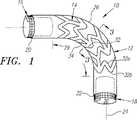
さて、図面に戻ると、図1は、本発明によるステント移植片10の好ましい第1の実施形態を示しており、このステント移植片は、管状移植片12と、外側骨格14と第1と第2の巻きシートステント16,18とを備えている。管状移植片12は、それらの間に長手軸24を限定する第1および第2の端部20,22と、外周部28および内側の内腔30を限定する外周壁26とを有する。管状移植片12は、ポリエステル、ポリテトラフルオロエタリン、ポリエチレンテレフタレート、ポリテトラフルオロエチレン、ポリウレタンなどのポリマー材料であるのが好ましい人体に適合した種々の材料から作ることができる。
【0020】
外側骨格14は、外周壁26に取り付けられ、複数の曲がりくねった要素32を有する。外側骨格14は、ニチノールやステンレス鋼などの人体に適合した金属材料であるのが好ましい種々の半ば剛な材料から作ることができる。この材料は、ステント移植片10の関節運動、外側骨格14の収縮状態-拡張状態間での収縮、および拡張の少なくとも1つを容易にするために、後述するように、弾性変形可能か、形状記憶特性を有するか、塑性変形可能かの少なくともいずれかである。外側骨格14は、シート材料からエッチング、切断、その他によって形成された個々の曲がりくねった要素32を有する平坦なシート材料を用いて作ることができる。これと択一的に、外側骨格14は、例えば各曲がりくねった要素32をワイヤの単一のストランドから形成するなどによって、ワーヤのような材料から作ることができる。
【0021】
外側骨格14は、外周壁26の外側またはこれと択一的に外周壁26の内側に取り付けることができる。「外側骨格」という文言は、上記箇所のどれもを包含する意図であり、他の箇所に勝る或る箇所に限定する意図ではない。外側骨格14は、縫い合わせ、ワイヤ、ステープルなどの機械的固定手段、接着剤、または熱接合,化学的接合,超音波接合などの接合処理によって取り付けることができる。
【0022】
各曲がりくねった要素32は、外周壁26の少なくとも一部に沿って「周方向」および「軸方向」の両方向に延びる。「周方向」とは、曲がりくねった要素32が、好ましくは円形または楕円形である外周壁26を取り囲むように、例えば外周壁26の円周または他の外周を概ね回るように延びることを指す一方、「軸方向」とは、曲がりくねった要素32が、長手軸24と概ね平行に外周壁26に沿って延びることを指す。こうして、各曲がりくねった要素32は、例えば急峻な「Z」または丸い「U」の形状の互いに連結された要素からなる概ね「ジグザグ」の形状を限定する。
【0023】
図1,2に示された第1の実施形態では、曲がりくねった要素14は、概ね真直ぐな真直軸方向域32aと、外周壁26の周りに実質上周方向に延びる湾曲した湾曲外周域32bとが一体に形成された複数のジグザグな要素によって限定される。従って、曲がりくねった要素32は、ステント移植片10が長手軸24に対して実質上横方向に向けられたとき、隣接する曲がりくねった要素32相互間での関節運動を容易にするような多数セルの外側骨格14を提供する。
【0024】
或る実施形態では、曲がりくねった要素32は、好ましくは隣接する曲がりくねった要素32間に実質上軸方向に延びる接続要素34によって連結される。接続要素34は、曲がりくねった要素が平坦なシートから作られる場合、エッチングまたは切断によって形成されるか、曲がりくねった要素32に従来の手法で取り付けられたワイヤのストランドであるかのいずれかである。これと択一的に、曲がりくねった要素32は、管状移植変12の外周壁26に個々に取り付けられる分離した構造にすることができる。
【0025】
巻きシートステント16,18は、管状移植片の各端部20,22の外周壁26の内側に取り付けられる。巻きシートステント16,18は、自動的に拡張してもよいが、例えばバルーンや他の拡張しうる部材(図示せず)を用いてより大きい直径になるようにラチェット噛合するなど機械的に拡張できる方が好ましい。
【0026】
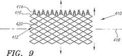
巻きシートステント16,18は、拡張しうる設計、拡張しうる座屈防止セグメント、拡張しうるクラウンをつけた端部のうちの少なくとも1つを有することができる。例えば、図9には、一杯に拡張しうる巻きシートステント410が示されており、この巻きシートステントは、個々の弾性メッシュ要素420を限定し、側縁416縁に沿ってメッシュ要素420に受け入れられるための歯414をもつ実質的に平坦なメッシュ構造412から形成されている。このメッシュ構造412は、長手軸418および円周または外周(図示せず)を長手軸418と実質上直交する平面内で限定すべく、ロール状に巻き込まれる。メッシュ構造412は、ステンレス鋼などの塑性変形しうる材料から作られる。
【0027】
しかし、好ましい実施形態では、研磨か、熱処理かの少なくともいずれかを施されたニチノールなどの形状記憶材料から作られる。例えばオーステナイト相などの応力のない状態において、メッシュ要素420は、好ましくは「伸びた」状態、即ちメッシュ要素がメッシュ構造412の周辺の周りへ拡張して、メッシュ構造412が、例えばステント410が内部に移植されるべき血管の断面と実質上同じになる拡大した寸法をとるように偏らされた状態を呈する。また、メッシュ要素420は、「伸びない」状態、即ちメッシュ要素がメッシュ構造420の周辺の周りから圧縮されて、メッシュ構造412が、実質上縮小した寸法をとる状態を呈する。これは、メッシュ構造412の材料であるニチノールが、例えば熱処理後の冷却によってマルテンサイト相に変態することによって達成される。そうすると、ステント410は、既に述べたようにステント移植片への取り付けのための収縮した供給プロフィルに巻き込まれ、あるいは折り畳まれる。
【0028】
ステント410が血管内に移植されると、メッシュ構造412は、例えばオーステナイト相などの応力のない状態に戻る、つまり伸びて、血管壁を拡大するように拡張する。血管によってステントに半径方向の圧縮力が加えられると、メッシュ要素420は周辺の周りから圧縮され、これによってステント410の再巻き込みが可能になるので、従来の巻きシートステントに実質上半径方向の圧縮力が加わったとき生じていた座屈の可能性がなくなる。
【0029】
図10A,Bは、巻きシートステント510の他の実施形態を示しており、この巻きシートステントは、メッシュ構造で形成された伸びうる座屈防止セグメント512を有し、この座屈防止セグメントは、巻きシート部分514部分に取り付けられる。巻きシート部分514は、側縁518に沿った歯516を有し、重畳する内側および外側の軸方向部分524,526と、長手軸520と、外周522とを限定するようにロールされあるいは巻き込まれて、座屈防止セグメント512が、軸方向、つまり長手軸520と実質上平行に延びるようになる。前の実施形態と同様に、座屈防止セグメント512は、ニチノールから作ることができ、このニチノールは、熱処理され、引き伸ばされた後、冷却されて引き伸ばされない状態になる。軸方向に向いた座屈防止セグメント512は、半径方向の圧縮力を受けたとき、上述のように外周522の周りに圧縮されるメッシュ要素524を設けることによって、巻きシートステント510全体が巻き戻るのを容易にする。こうして、ステント510は、外周の周りに一般に圧縮されない巻きシートステントの利点と、引き伸ばしうるステント構造の利点を組み合せるのである。
【0030】
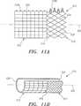
図11A,11Bを参照すると、ステント610の他の実施形態が示されており、このステントは、座屈防止セグメント、即ち「クラウンをつけた端部616」を巻きシート部分612部分の一端614に有する。巻きシート部分612および座屈防止セグメント616は、側縁620に沿って歯618a,618bを有するとともに、長手軸620および周囲624を限定するように巻かれる。座屈防止セグメント616は、好ましくは研磨され、所望の形状に熱処理され、冷却されて引き伸ばされない状態となった後、崩れて巻かれた供給プロフィルに巻き込まれる。移植された後、座屈防止セグメント616内のメッシュ要素626は、ステント610が半径方向の圧縮力を受けると、上述の実施形態と同様に圧縮され、ステント610の端部をテーパ状にさせる。これと択一的に、座屈防止セグメント616の端部628は、(図示しないが)外側に張り出させることができ、これによってステントが、血管内への移植の際に半径方向の圧縮力を受けたときに、実質上均一な寸法をとるように部分的に巻き戻る。
【0031】
巻きシートステント16,18も、体内通路内へのステント移植片10のアンカリングを強めるために、外側へ向いたフックやバー(図示せず)を備えることができる。血液凝固性の物質(図示せず)を、体内通路の壁に対するシールを強めるため、巻きシートステント16,18の外面、またはこれと択一的に管状移植片12の端部20,22に備えることができる。本発明によるステント移植片と一緒に用いられる適切な巻きシートステントに関する情報は、1986年5月25日にKreamerに付与された米国特許第4,577,631号、1991年4月16日にDerbyshireに付与された米国特許第5,007,926号、1992年10月28日にLau et al.に付与された米国特許第5,158,548号、1993年7月27日にKreamerに再発行された米国特許第Re 34,327号、1995年6月13日にWilliamsに付与された米国特許第5,423,885号、1995年8月15日にKhosravi et al.に付与された米国特許第5,441,515号、1995年8月22日にSigwartに付与された米国特許第5,443,500号に見い出すことができる。これらの参考文献の開示内容およびこれらに引用された他の内容は、参考として本明細書に明白に一体化されている。
【0032】
図3A,Bを参照すると、ステント移植片10は、図3Bに示された拡張状態から図3Aに示された収縮状態へ圧縮することができる。好ましい実施形態では、外側骨格14は、拡張状態をとるように弾性的に偏らせられるが、患者の血管系内へのステント移植片10の導入を容易にするため、収縮状態に拘束することもできる。
【0033】
例えば、ステント移植片10は、収縮状態に拘束されて、(図示しない)血管に経皮的に導入される。ステント移植片10は、目標治療箇所である例えば大動脈や他の血管(図示せず)内まで前進させられて、外側骨格14を拡張状態に自動的に広げるように展開させられる。そして、巻きシートステント16,18は、管状移植片12の端部20,22を治療箇所の近傍の所定位置に実質上噛み込ませてアンカリングするような所望の寸法に拡張させられる。これと択一的に、巻きシートステント16,18が、(図示しない)分離した構成部材として設けられている場合は、これらの巻きシートステントは、実質上展開して、先に展開した管状移植片12の端部20,22にアンカリングするように拡張する。
【0034】
外側骨格14は、ステント移植片10に半径方向の圧縮力を単に加えることによって収縮状態に保持され、ステント移植片10を例えばスリーブ内に拘束する。これと択一的に、外側骨格14がニチノールから作られた場合、ニチノールのマルテンサイトの特性が、半径方向に圧縮された後のステント移植片10を収縮状態に実質上保持する。外側骨格14の曲がりくねった要素32の「ジグザグ」な形状は、ステント移植片が半径方向の圧縮力を受けたとき、ステント移植片10が図3Aに示すように半径方向に実質上均一に圧縮されるのを容易にする。これによって、外側骨格14や管状移植片12における局部応力の虞が最小化される。
【0035】
外側骨格14が自動的に拡張状態をとるとき、曲がりくねった要素32は、好ましくは実質上拡張して管状移植片12の外周壁26を支え、これによって、内腔30を図3Bに示すように実質上塞がれない開状態に維持し、修復された治療箇所を通る血液の流れを容易にする。これと択一的な実施形態では、外側骨格14は、最初は収縮状態に作られるが、ステント移植片10が治療箇所で展開した後、例えばバルーンや他の拡張できる部材を用いて拡張状態に塑性変形できるものであり、その価値は当該分野の専門家が認めるところである。
【0036】
外側骨格14の複数の曲がりくねった要素32によって提供される多セル形状は、前進中や治療箇所での展開の際にステント移植片10が苦痛を受ける生体組織に順応することを容易にする。ステント移植片10が例えば血管の急な湾曲部分の周りを進むときに、ステント移植片10に実質上横方向の力が加わると、ステント移植片10は、隣接する曲がりくねった要素32相互間で容易に関節運動して、血管の形状に順応する。さらに、各曲がりくねった要素32のジグザグな要素が、弾性変形でき、これによって、ステント移植片が局所的な人体組織の条件に順応することが更に容易化される。このように、本発明によるステント移植片10は、実質上剛なアンカリングステント16,18の間に延びる実質上柔軟な中間域29を有する。中間域29は、管状移植片12が治療箇所の人体組織に順応することを可能にし、外側骨格14は、崩壊または座屈しないように管状移植片12を実質上支える。
【0037】
図4には、外側骨格114の他の好ましい実施形態が示されており、この外側骨格は、管状移植片112(破線)の外周壁126に取り付けられた1つ以上の曲がりくねった要素132を有する。この曲がりくねった要素は、ステント移植片の長手軸124に沿って実質上軸方向に延びている。各曲がりくねった要素132は、外周壁126に沿って実質上軸方向に延びる概ね正弦曲線の形状を限定するとともに、実質上横方向の外周要素134を有し、隣接する外周要素134は交互に湾曲する湾曲要素136によって、概ね正弦曲線の形状を限定するように連結されるのが好ましい。
【0038】
好ましい実施形態では、複数の曲がりくねった要素は、外周壁126の外周の周りに実質上均一に分布させて設けることができる。例えば、図5A〜Dに示すように、1対の曲がりくねった要素132を、互いに対向する外周壁126に取り付けることができる。
【0039】
図5A〜Dには、1対の軸方向の曲がりくねった要素132a,132bをもつステント移植片110が示されており、このステント移植片は、拡張した状態から収縮した状態に巻かれる。外側骨格114は、図5Aの拡張状態をとるように付勢されるのが好ましい。曲がりくねった要素132a,132bの間に実質上軸方向に延びる空間133空間によって、ステント移植片110片の両端の巻きシートステント(図示せず)を含むステント移植片110は、図5Bに示すように平坦にすることができる、そうすると、ステント移植片110片の一端は、図5Cに示すように、ステント移植片110全体が図5Dに示す収縮状態に完全に巻かれるまで、巻きシートステントと同様に巻き込まれ、これによって減少したプロフィルが提供される。すると、ステント移植片110は、収縮状態で保持されて、目標箇所で展開されるまで患者の血管系に導入されて前進させられ、この目標箇所で拡張した状態に自動的に広がる。
【0040】
図6には、ステント移植片210の他の好ましい実施形態が示されている。このステント移植片は、第1端部220と第2端部222との間に実質上テーパ状の外形を有する。前述の実施形態と同様に、ステント移植片210は管状移植片212を有し、この管状移植片に、弾性的で柔軟な領域を提供すべく外側骨格214が取り付けられる。巻きシートステント216,218は、端部220,222を人体通路内にアンカリングすべく、管状移植片212の端部220,222に取り付けられる。管状移植片212片の第2の端部222は、第1の端部220よりも実質上小さい直径をもっていて、テーパ状の血管の人体構造に実質上順応するか、第1のより大きい血管と第2のより小さい血管との間に延びるようになっている。
【0041】
図8を参照すると、直前で述べたテーパ上のステント移植片は、腹部大動脈252から分岐254を経て腸骨動脈256a,256bに延びる大動脈瘤250を修復するための方法に用いられる。ステント移植片210は、収縮した状態でより大きい第1端部220を腹部大動脈252に向けて分岐254を通って導入される。例えば、ステント移植片210は、カテーテル供給器具(図示せず)に載せられて周辺動脈(図示せず)内へ経皮的に導入され、同側の腸骨動脈256a内へ入り、分岐254を通って第1端部220が損傷していない腹部大動脈252に達するまで前進させられる。ここで、ステント移植片210は、例えば展開の際に外側骨格214が自動的に拡張するとき、拡張した状態へ展開されて広げられる。ステント移植片210上の巻きシートステント216,218は、拡張させられて、腹部大動脈252の損傷していない箇所および同側の腸骨動脈256aにステント移植片210を実質上アンカリングし、シールする。
【0042】
反対側の腸骨動脈256bは、血管オクルーダ(閉鎖具)260によって実質上永続的に塞がれ、大腿−大腿のバイパス移植片270が、大腿動脈258の間またはこれと択一的に腸骨動脈256の間に取り付けられて、同側の腸骨動脈256aから反対側の腸骨動脈256b以遠への血流を可能にする。
【0043】
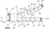
図7には、本発明の他の態様による分岐を修復するためのステント移植片310が示されている。ステント移植片310は、複数の管状セグメント、即ち第1主セグメント312と、この第1主セグメント312から延び出す第2延長セグメント314と、第3セグメントつまり第1主セグメント312上のカラー318に取り付けうる「連結リム316」とを有する。第1主セグメント312は、長手軸324をそれらの間に限定する第1端部230と第2分岐端部322とを有し、この第2分岐端部322から互いに隣接して第2延長セグメント314とカラー318が延び出している。
【0044】
第1主セグメント312と第2延長セグメント314は、夫々第1外周壁326と第2外周壁328を有し、これらの外周壁は、一体に形成されるか、互いに取り付けられる分離した部分として形成される。第1外周壁326は、第1端部320から延び出して第1主セグメント321を通り、第2外周壁328で限定される第1分岐内腔330aと、カラー330bによって少なくとも部分的に限定される第2分岐内腔330bとに分岐する。
【0045】
外側骨格332は、前述の曲がりくねった要素と同様に、第1外周壁326と第2外周壁328の少なくとも1つおよび/またはカラー318に取り付けられる。好ましくは、曲がりくねった要素の第1のセット334aが、第1主セグメント312を支えるべく第1外周壁326に取り付けられ、曲がりくねった要素の第2のセット334bが、第2延長セグメント314を支えるべく第2外周壁328に取り付けられる。曲がりくねった要素334は、各外周壁326,328に個々に取り付けられるか、隣接する曲がりくねった要素が、上述のように1つ以上の(図示しない)接続要素で互いに連結されるかの少なくともいずれかにできる。
【0046】
第1の巻きシートステント336は、第1端部320を体内通路内に実質上アンカリングおよび/またはシーリングするために、第1端部320に取り付けられる。同様に、第2の巻きシートステント338は、第2延長セグメント314の遠位端340に取り付けられる。
【0047】
連結リム316は、1つ以上の曲がりくねった要素350が取り付けられる第3外周壁348を有し、これによってステント移植片310の外側骨格332が更に限定される。第3の巻きシートステント342は、連結リム316の第1端部、つまり遠位端344に取り付けられる。連結リム316の第2端部、つまり近位端346は、例えば重ね接続またはこれと択一的に他の巻きシートステント(図示せず)を用いて第1主セグメント312のカラー318に取り付けることができる。
【0048】
外側骨格332は、前述のステント移植片と同様に、人体通路内への導入を容易化するための収縮状態と、人体通路内で展開するための拡張状態との間で制御される。例えば、各曲がりくねった要素334a,334b,350は、収縮状態へ半径方向に圧縮でき、拡張状態をとるように付勢されることができる。
【0049】
好ましい実施形態では、第1主セグメント312の第1端部320は、拡張状態で腹部大動脈の損傷していない箇所の直径に実質上相当する寸法を有する。第2延長セグメント314と連結リム316の遠位端340,344は、拡張状態で第1主セグメント312の寸法よりも実質上小さい寸法、好ましくは腸骨動脈の損傷していない箇所に実質上相当する寸法を有する。
【0050】
第1主セグメント312と第2延長セグメント314は、収縮状態に半径方向へ圧縮でき、図8に示されたと同様に、患者の血管系内で大動脈-腸骨動脈分岐部(図示せず)の動脈瘤などの分岐した治療箇所へ向けられる。第1端部320は、第2延長セグメント314を第1の腸骨動脈内に延ばし、カラー318を第2の腸骨動脈の方に向けて、動脈瘤近傍の腹部大動脈の損傷していない箇所と整列させられる。第1主セグメント312と第2延長セグメント314は、拡張した状態に展開されて広がり、第1,第2の巻きシートステント336,338は、損傷していない腹部大動脈と第1の腸骨動脈の壁に実質上噛み込むように夫々拡張する。
【0051】
連結リム316は、収縮状態で第2の腸骨動脈内に前進し、その近位端346をカラー318と整列させる。そして、連結リム316は、拡張させられて拡張状態に広げられ、その近位端346がカラー318に実質上噛み合う。第3の巻きシートステント342は、第2の腸骨動脈の損傷していない箇所に噛み込んでシールするように拡張する。
【0052】
こうして、大動脈-腸骨動脈分岐部の損傷箇所は、本発明によるステント移植片310を用いて完全にバイパスされる。柔軟な外側骨格332は、ステント移植片310が分岐した治療箇所の人体組織に実質上順応することを可能にするとともに、管状の移植片セグメント312,314を支えて、血流を収容する実質上塞がれずに開いた内腔を提供する。巻きシートステント336,338,342は、ステント移植片310の各端部320,340,344に実質上アンカリングし、および/またはステント移植片310を血管壁に対して実質上シールする。
【0053】
本発明は、種々の変更例と択一的な実施形態が可能であるが、特定の実施形態のみが図面に示され、ここに詳細に説明された。しかし、本発明が、ここに開示された特定の実施形態や方法に限定されず、それとは逆に、添付の請求項の真髄と範囲内に入る総ての変更例や均等物や択一例に及ぶものと理解されなければならない。
【図面の簡単な説明】
【図1】 本発明による外側骨格をもつステント移植片の斜視図である。
【図2】 上記外側骨格を限定する複数の曲がりくねった要素の第1実施形態を示す図1のステント移植片の詳細側面図である。
【図3】 収縮状態および拡張状態にあるステント移植片を夫々示す図1のステント移植片の3-3線に沿う断面図である。
【図4】 管状移植片(破線)に取り付け得る曲がりくねった要素の他の実施形態を示す斜視図である。
【図5】 ステント移植片を収縮状態に巻く方法を示す本発明によるステント移植片の端面図である。
【図6】 テーパ状の外形をもつステント移植片の他の実施形態を示す斜視図である。
【図7】 分岐する主セグメントと延長セグメントと取り付け可能な連結リムとをもつステント移植片の他の実施形態を示す斜視図である。
【図8】 分岐管の動脈瘤を治療するために、分岐を横切ってステント移植片を移植する方法を示す腹部の断面図である。
【図9】 本発明によるステント移植片と一緒に用いられる一杯に拡張し得るステントの側面図である。
【図10】 座屈防止セグメントをもつステントの夫々端面図および側面図である。
【図11】 拡張し得る端部をもつステントの側面図および斜視図である。
【符号の説明】
10 ステント移植片
12 管状移植片
14 外側骨格
16,18 巻きシートステント
20 第1端部
22 第2端部
24 長手軸
26 外周壁
29 柔軟な中間域
30 内腔
32 曲がりくねった要素
34 接続要素[0001]
(Technical field)
The present invention relates generally to prostheses for implantation in body cavities, and more particularly to stent grafts having a flexible outer skeleton attached to a tubular graft.
[0002]
(Background technology)
Graft prostheses are often transplanted into blood vessels, particularly arteries such as an aorta that suffers from an aneurysm and is cut by atherosclerosis that includes multiple stenosis. For example, an aortic aneurysm may occur in a patient's eg iliac bifurcation of the abdominal aorta, in which case it must be treated before the vessel wall ruptures. In order to treat blood vessels damaged by such diseases, procedures including the use of graft prostheses are generally performed.
[0003]
Several graft prostheses have been proposed so far in which a stent is attached to a tubular graft. The tubular graft is a porous or non-porous tubular structure that is compatible with a living body, and a stent structure such as a wire mesh is attached to the tubular graft. The stent is biased to assume an expanded profile corresponding to the target treatment site, but is constrained to a contracted state to facilitate introduction into the patient's vasculature. The graft prosthesis is introduced percutaneously in a contracted state, advanced to the treatment site in the blood vessel, released to assume the expanded state, repairing the treatment site, or creating a bypass at the treatment site .
[0004]
One of the problems often associated with such prostheses is the effective fixation of the tubular graft to the treatment site. If the released prosthesis does not sufficiently bite into the blood vessel wall near the treatment site, the graft prosthesis may move after transplantation, exposing the damaged blood vessel wall. A plastically expandable stent structure is provided in an attempt to more directly control the engagement between the graft prosthesis and the vessel wall. However, such expandable structures require the use of a balloon or other expansion member to expand the stent structure to an expanded state. The use of this balloon or the like can cause non-uniform expansion of the stent structure and balloon rupture.
[0005]
In addition to a plastically deformable stent, a wound sheet stent structure has been proposed. The wound sheet stent can enhance anchoring into the blood vessel because the size of the fully expanded stent can be controlled more precisely. However, the wound sheet stent is substantially rigid in the direction perpendicular to the longitudinal axis, so that the graft prosthesis is potentially less flexible and effective under conditions that hurt human tissue Cannot be transplanted.
[0006]
Accordingly, there is a growing need for an improved stent graft that has improved flexibility and provides sufficient anchoring into the blood vessel.
[0007]
(Summary of Invention)
The present invention is directed to a stent graft having an outer skeleton attached to a tubular graft. According to one aspect of the present invention, a stent-graft is provided, the stent-graft comprising a tubular graft having an outer peripheral wall defining an outer periphery and a lumen, the lumen including a first end of the tubular graft and An axial direction extends between the second ends. The outer skeleton is attached to the outer peripheral wall and has one or more tortuous elements, each tortuous element extending circumferentially so as to generally surround the outer peripheral wall of a circular, oval or other suitable shape. And it also extends in the axial direction along at least a part of the outer peripheral wall. Stent isConsisting of a wound sheet stent In order to firmly anchor the first end and the second end into the body passage, these endsInside the outer wall of the Provided.
[0008]
In a preferred embodiment, each tortuous element is a zigzag structure that extends circumferentially around the outer peripheral wall of the tubular graft. More preferably, the plurality of tortuous elements are distributed axially along the outer peripheral wall so that the tubular graft can articulate between adjacent tortuous elements. The tortuous elements are at least either individually attached to the outer peripheral wall or connected to each other by one or more connecting elements extending between adjacent elements.
[0009]
In another preferred embodiment, each tortuous element has a generally sinusoidal shape extending axially along the outer peripheral wall. The plurality of tortuous elements are preferably distributed substantially evenly along the outer periphery of the outer peripheral wall. Preferably, each of these tortuous elements has a substantially transverse peripheral element, and adjacent peripheral elements are connected by alternating curved elements, thereby exhibiting a generally sinusoidal shape.
[0010]
The outer skeleton of the stent-graft is preferably controllable between a contracted state for ease of introduction into the body passage and an expanded state for deployment within the body passage. The outer skeleton substantially supports the tubular graft in the expanded state and holds the lumen of the tubular graft substantially open. In a preferred embodiment, the outer skeleton can be radially compressed into a contracted state and biased to assume an expanded state. Alternatively, the contracted state of the outer skeleton can be achieved by flattening the outer skeleton and then winding it in the circumferential direction.
[0011]
Tubular implants can be made from polymeric materials such as polyester, polytetrafluoroethalin, dacron, teflon, polyurethane. The outer skeleton can be attached to the tubular graft by stitching, staples, wires, adhesives, etc., or alternatively to the tubular graft by thermal bonding, chemical bonding, ultrasonic bonding. The outer skeleton can be made from a metallic material such as stainless steel or nitinol, and can be a flat wound sheet with one or more tortuous elements formed therein, or a wire formed into a tortuous shape.
[0012]
In alternative embodiments, the first and second ends of the tubular graft have a similar cross-section, or the first end of the tubular graft is substantially greater than the cross-sectional area of the second end. It has a small cross-sectional area. Further, the outer skeleton is attached to the outer or inner surface of the tubular graft or embedded in the wall of the tubular graft.
[0013]
According to another embodiment of the present invention, there is provided a stent-graft comprising a first tubular graft segment having a first end and a second bifurcated end for mounting in a branch tube, wherein the first tubular graft is provided. The one segment has a first outer peripheral wall. A second tubular graft segment extends from the second bifurcated end, and the second tubular graft segment has a second outer peripheral wall. An outer skeleton is attached to at least one of the first outer peripheral wall and the second outer peripheral wall, and the outer skeleton has one or more tortuous elements, and each tortuous element has an outer circumference to which it is attached. Extending circumferentially and axially along at least a portion of the wall.
[0014]
A wound sheet stent is provided at the first end to sufficiently anchor the first end into the body passage. Similarly, a wound sheet stent is provided on the second tubular graft segment opposite the second end of the first tubular graft segment.
[0015]
The stent-graft preferably also has a third tubular graft that can be attached to the second bifurcated end, the third tubular graft having a third outer peripheral wall. The outer skeleton also has one or more tortuous elements that can be attached to the third outer peripheral wall.
[0016]
Thus, a stent-graft according to the present invention has a substantially flexible region that substantially matches the human tissue at the treatment site. This flexible region is limited by an outer skeleton that is attached to the tubular graft with one or more tortuous elements. The torsion element is at least either elastic enough to facilitate articulation between adjacent torsion elements or at least one of compression and expansion of the torsion element itself It is.
[0017]
The A tent graft is a wound sheet stent that is attached to the end of a tubular graft for at least one of substantial sealing and anchoring of the tubular graft near the treatment site.Ru A tool member. Thus, the stent-graft provides effective sealing and anchoring into the human body passage while mediating the pain imparted to human tissue.
[0018]
(Best Mode for Carrying Out the Invention)
Other objects and features of the present invention will become apparent from the following description taken in conjunction with the accompanying drawings.
[0019]
Turning now to the drawings, FIG. 1 shows a first preferred embodiment of a
[0020]
The outer skeleton 14 is attached to the outer
[0021]
The outer skeleton 14 can be attached to the outside of the outer
[0022]
Each
[0023]
In the first embodiment shown in FIGS. 1 and 2, the tortuous element 14 includes a straight axial region 32a that is generally straight and a curved curved outer region 32b that extends substantially circumferentially about the outer
[0024]
In certain embodiments, the
[0025]
The
[0026]
The
[0027]
However, in a preferred embodiment, it is made from a shape memory material such as Nitinol that has been polished and / or heat treated. In an unstressed state, such as an austenite phase, the
[0028]
When the
[0029]
FIGS. 10A and B show another embodiment of a
[0030]
Referring to FIGS. 11A and 11B, another embodiment of a
[0031]
The
[0032]
Referring to FIGS. 3A and B, the stent-
[0033]
For example, the stent-
[0034]
The outer skeleton 14 is held in a contracted state by simply applying a radial compressive force to the stent-
[0035]
When the outer skeleton 14 is automatically expanded, the
[0036]
The multi-cell shape provided by the multiple
[0037]
FIG. 4 shows another preferred embodiment of the
[0038]
In a preferred embodiment, the plurality of tortuous elements can be provided with a substantially uniform distribution around the outer periphery of the outer
[0039]
5A-D show a
[0040]
In FIG. 6, another preferred embodiment of a stent-
[0041]
Referring to FIG. 8, the taper stent graft just described is used in a method for repairing an
[0042]
The contralateral
[0043]
FIG. 7 illustrates a stent-
[0044]
The first
[0045]
The
[0046]
A first
[0047]
The connecting
[0048]
The
[0049]
In a preferred embodiment, the
[0050]
The first
[0051]
The connecting
[0052]
Thus, the aortic-iliac bifurcation lesion is completely bypassed using the
[0053]
While the invention is susceptible to various modifications and alternative embodiments, only specific embodiments thereof are shown in the drawings and have been described in detail herein. However, the invention is not limited to the specific embodiments and methods disclosed herein, but on the contrary, to all modifications, equivalents and alternatives falling within the spirit and scope of the appended claims. It must be understood that it extends.
[Brief description of the drawings]
FIG. 1 is a perspective view of a stent-graft having an outer skeleton according to the present invention.
2 is a detailed side view of the stent-graft of FIG. 1 showing a first embodiment of a plurality of tortuous elements that define the outer skeleton. FIG.
3 is a cross-sectional view taken along line 3-3 of the stent-graft of FIG. 1 showing the stent-graft in a contracted state and an expanded state, respectively.
FIG. 4 is a perspective view showing another embodiment of a serpentine element that can be attached to a tubular graft (dashed line).
FIG. 5 is an end view of a stent-graft according to the present invention showing a method of winding the stent-graft in a contracted state.
FIG. 6 is a perspective view of another embodiment of a stent-graft having a tapered profile.
FIG. 7 is a perspective view of another embodiment of a stent-graft having a bifurcated main segment, an extension segment, and an attachable connecting rim.
FIG. 8 is a cross-sectional view of the abdomen showing a method of implanting a stent-graft across a bifurcation to treat a branch vessel aneurysm.
FIG. 9 is a side view of a fully expandable stent for use with a stent graft according to the present invention.
FIG. 10 is an end view and a side view, respectively, of a stent having an anti-buckling segment.
FIG. 11 is a side and perspective view of a stent with an expandable end.
[Explanation of symbols]
10 Stent graft
12 Tubular graft
14 Outer skeleton
16,18 roll sheet stent
20 First end
22 Second end
24 Long axis
26 outer wall
29 Flexible midrange
30 lumens
32 Winding elements
34 Connection elements
Claims (33)
Translated fromJapanese外周およびその内側の内腔(30)を限定する外周壁(26)を有し、上記内腔(30)が第1端部(20)と第2端部(22)の間に軸方向に延在する管状移植片(12)と、
複数の独立の曲がりくねった要素からなり、上記外周壁(26)の中間部分に取り付けられる外側骨格であって、上記各曲がりくねった要素(14)は、上記外周壁(26)の少なくとも一部に沿って周方向にも軸方向にも延び、上記管状移植片(12)の隣接する曲がりくねった要素(14)間での関節運動を提供すべく上記外周壁(26)に沿って軸方向に互いに位相を揃えて分布させられるとともに、上記内腔を実質上開いた状態に保持するための拡張状態に偏らせられ、また、体内通路内への導入を容易にするための収縮状態に束縛されうるような外側骨格(14)と、
上記第1端部(20)を体内通路内に実質上アンカリングするために、第1端部(20)の外周壁(26)の内側に取り付けられた巻かれたシートステントからなるステント(16)とを備えたステント移植片。A stent-graft (10) comprising:
An outer peripheral wall (26) that defines an outer periphery and an inner lumen (30); An extending tubular graft (12);
An outer skeleton composed of a plurality of independent winding elements and attached to an intermediate portion of the outer peripheral wall (26), wherein each of the winding elements (14) extends along at least a part of the outer peripheral wall (26). Both circumferentially and axially extending and phased axially along the outer peripheral wall (26) to provide articulation between adjacent tortuous elements (14) of the tubular graft (12) So that the lumen can be biased to an expanded state to keep the lumen substantially open, and can be constrained to a contracted state to facilitate introduction into the body passage. The outer skeleton (14),
A stent (16) comprising awound sheet stent attached tothe inside ofthe outer peripheral wall (26) of the first end (20) for anchoring the first end (20) substantially into the body passage. A stent-graft.
外周およびその内側の内腔(130)を限定する外周壁(126)を有し、上記内腔(130)が第1端部と第2端部の間に軸方向に延在する管状移植片(112)と、
複数の独立の曲がりくねった要素からなり、上記外周壁(126)の中間部分に取り付けられる外側骨格であって、上記各曲がりくねった要素(132)は、上記外周壁(126)に沿って実質上軸方向に延びる概ね正弦曲線の形状を限定するとともに、上記内腔を実質上開いた状態に保持するための拡張状態に偏らせられ、また、体内通路内への導入を容易にするための収縮状態に束縛されうるような外側骨格(114)と、
上記第1端部を体内通路内に実質上アンカリングするために、第1端部の外周壁(126)の内側に取り付けられた巻かれたシートステントからなるステント(16)とを備えたステント移植片。A stent-graft (110) comprising:
A tubular graft having an outer peripheral wall (126) defining an outer periphery and an inner lumen (130) therein, the lumen (130) extending axially between the first end and the second end (112)
An outer skeleton composed of a plurality of independent winding elements and attached to an intermediate portion of the outer peripheral wall (126), wherein each of the winding elements (132) substantially extends along the outer peripheral wall (126). A generally sinusoidal shape extending in the direction,biased to an expanded state to hold the lumen substantially open, and in a contracted state to facilitate introduction into the body passage An outer skeleton (114) that can be bound to
A stent comprising a wound sheet stent (16) mounted inside the outer peripheral wall (126) of the first end for substantially anchoring the first end into the body passage Graft.
外周およびその内側の内腔(30)を限定する外周壁(26)を有し、上記内腔(30)が第1端部(20)と第2端部(22)の間に軸方向に延在する管状移植片(12)と、
上記外周壁(26)に取り付けられ、隣接する曲がりくねった要素(14)相互間での管状移植片(12)の関節運動を提供すべく、上記外周壁(26)に沿って軸方向に所定の形状で互いに位相を揃えて分布させられ、各曲がりくねった要素(14)が上記管状移植片(12)の外周壁の周りに実質上周方向に延びるジグザグな形状を限定する複数の曲がりくねった要素(14)からなり、各曲がりくねった要素(14)が、上記内腔(30)を実質上開いた状態に保持するための拡張状態に偏らせられ、また、体内通路内への導入を容易にするための収縮状態に束縛されうるような外側骨格(14)と、
上記第1端部(20)または第2端部(22)の少なくともいずれかを体内通路内に実質上アンカリングするために、第1端部(20)または第2端部(22)の外周壁(26)の内側に取り付けられた巻かれたシートステントからなるステントとを備えたステント移植片。A stent-graft (10) comprising:
An outer peripheral wall (26) that defines an outer periphery and an inner lumen (30); An extending tubular graft (12);
A predetermined axially along the outer peripheral wall (26) to provide articulation of the tubular graft (12) between the adjacent tortuous elements (14) attached to the outer peripheral wall (26). A plurality of tortuous elements that are distributed in phase with each other, each tortuous element (14) defining a zigzag shape extending substantially circumferentially around the outer peripheral wall of the tubular graft (12) (consists 14), each serpentine element(14) is biased to the expanded state for holding the substantially open position the bore (30), also facilitates the introduction into the body passageAn outer skeleton (14) that canbe constrained to contraction for
An outer periphery of the first end (20) or the second end (22) for anchoring at least one of the first end (20) or the second end (22) into the body passage. A stent graftcomprising a stent comprising a wound sheet stent attached to the inside of a wall (26) .
上記管状移植片(312)の第1端部(320)と反対側の中間部分(312)から延び出すとともに、外周壁(328)および中間部分(312)と反対側の第2端部(340)を有する管状移植片延長セグメント(314)と、
この管状移植片延長セグメント(314)の隣接する曲がりくねった要素(334)相互間での上記管状移植片延長セグメント(314)の関節運動を提供すべく、上記管状移植片延長セグメント(314)の外周壁(328)に沿って所定の形状で分布させられてこの管状移植片延長セグメントに個々に取り付けられる複数の曲がりくねった要素(334b)と、
上記管状移植片延長セグメント(314)に隣接するカラー(318)とを更に備えたステント移植片。The stent graft (310) of claim14 , wherein the tubular graft is bifurcated, and the stent graft (310) comprises:
The tubular graft (312) extends fromthe intermediate portion (312) opposite to the first end (320) and extends to the outer peripheral wall (328)and the second end (340) opposite to the intermediate portion (312). ) a tubular graft extension segment (314) having,
To provide articulation of adjacent serpentine elementsof the tubular graft extension segment (314) (334) the tubular graft extension segment between each other (314), the outer circumference of the tubular graft extension segment (314) A plurality of tortuous elements (334b) distributed in a predetermined shape along the wall (328) and individually attached to the tubular graft extension segment;
A stent graft further comprisinga collar (318) adjacent to the tubular graft extension segment (314) .
外周壁(348)を有するとともに、上記管状移植片延長セグメント(314)に隣接する上記カラー(318)に取り付けられうる管状移植片連結リム(316)と、
この管状移植片連結リム (316)の隣接する曲がりくねった要素(350)相互間での上記管状移植片連結リム(316)の関節運動を提供すべく、上記管状移植片連結リム(316)の外周壁(348)に沿って所定の形状で分布させられてこの管状移植片延長セグメントに個々に取り付けられる複数の曲がりくねった要素(350)とを更に備えたステント移植片。The stent-graft (310) according to claim21 ,
A tubular graft connection rim (316) having an outer peripheral wall (348) and attachable to thecollar (318) adjacent to the tubular graft extension segment (314);
The outer periphery of the tubular graft connection rim (316) to provide articulation of the tubular graft connection rim (316) between adjacent tortuous elements (350) of the tubular graft connection rim (316). A stent graft further comprisinga plurality of tortuous elements (350) distributed in a predetermined shape along the wall (348) and individually attached to the tubular graft extension segment .
第1端部(320)と第2分岐端部(322)を有し、第1外周壁(326)を有する第1管状移植片セグメント(312)と、
上記第2分岐端部(322)から延び出し、第2外周壁(328)を有する第2管状移植片セグメント(314)と、
複数の独立の曲がりくねった要素からなり、上記第1外周壁(326)および第2外周壁(328)の少なくとも一方に取り付けられる外側骨格(334a,334b)であって、上記各曲がりくねった要素(334a,334b)は、取り付けられた夫々の外周壁の少なくとも一部に沿って周方向にも軸方向にも延び、隣接する曲がりくねった要素間での上記管状移植片の関節運動を提供すべく外周壁に沿って軸方向に互いに位相を揃えて分布させられるとともに、上記内腔を実質上開いた状態に保持するための拡張状態に偏らせられ、また、体内通路内への導入を容易にするための収縮状態に束縛されうるような外側骨格(334a,334b)と、
上記第1端部(320)を人体通路内に実質上アンカリングするために、第1端部(320)の外周壁(326)の内側に取り付けられた巻かれたステント(336)とを備えたステント移植片。A stent-graft mounted in a branch vessel,
A first tubular graft segment (312 ) having a first end (320) and a second branch end (322) and having a first outer peripheral wall (326);
A second tubular graft segment (314) extending from the second bifurcated end (322) and having a second outer peripheral wall (328);
An outer skeleton (334a, 334b) comprising a plurality of independent winding elements and attached to at least one of the first outer peripheral wall (326) and the second outer peripheral wall (328), each of the winding elements (334a) , 334b) extend circumferentially and axially along at least a portion of each attached outer peripheral wall to provide articulation of the tubular graft between adjacent tortuous elements In the axial direction and biased to an expanded state to keep the lumen substantially open, and to facilitate introduction into the body passage an outer skeleton such as may be bound to a contracted state(334a, 334b),
A wound stent (336) attached to the inside of the outer peripheral wall (326) of the first end (320) to substantially anchor the first end (320) into the human body passage. Stent graft.
外周およびその内側の内腔を限定する外周壁を有し、上記内腔が第1端部と第2端部の間に軸方向に延在する管状移植片と、
上記外周壁に取り付けられ、隣接する曲がりくねった要素相互間での管状移植片の関節運動を提供すべく、上記外周壁に沿って軸方向に所定の形状で互いに位相を揃えて分布させられ、各曲がりくねった要素が上記管状移植片の外周壁の周りに実質上周方向に延びるジグザグな形状を限定する複数の曲がりくねった要素と、
上記第1端部および第2端部を人体通路内に実質上アンカリングするために上記管状移植片の第1端部および第2端部の外周壁の内側に夫々固定される巻かれたシートステントからなるステントとを備えたステント移植片。A stent-graft,
A tubular graft having an outer peripheral wall defining an outer periphery and an inner lumen therein, the lumen extending axially between a first end and a second end;
Attached to the outer peripheral wall and distributed in phase with each other in a predetermined shape in the axial direction along the outer peripheral wall to provide articulation of the tubular graft between adjacent tortuous elements, A plurality of tortuous elements defining a zigzag shape in which the tortuous elements extend substantially circumferentially about the outer peripheral wall of the tubular graft;
Arolled sheet secured tothe inside ofthe outer peripheral wall of the first and second ends of the tubular graft, respectively, for anchoring the first end and the second end substantially into the human body passage. A stent graftcomprising a stent comprising a stent.
外周およびその内側の内腔を限定する外周壁を有し、上記内腔が第1端部と第2端部の間に軸方向に延在する管状移植片と、
上記管状移植片の中間部に取り付けられ、隣接する曲がりくねった要素相互間での管状移植片の関節運動を提供すべく、上記中間部に沿って軸方向に所定の形状で分布させられ、各曲がりくねった要素が上記管状移植片の外周壁の周りに実質上周方向に延びるジグザグな形状を限定するとともに、上記内腔を実質上開いた状態に保持するための拡張状態に偏らせられ、また、体内通路内への導入を容易にするための収縮状態に束縛されうる複数の曲がりくねった要素と、
上記第1端部および第2端部を人体通路内に実質上アンカリングするために上記管状移植片の第1端部および第2端部の外周壁の内側に夫々固定される巻かれたシートステントからなるステントとを備えたステント移植片。A stent-graft,
A tubular graft having an outer peripheral wall defining an outer periphery and an inner lumen therein, the lumen extending axially between a first end and a second end;
In order to provide articulation of the tubular graft between adjacent tortuous elements attached to the middle section of the tubular graft, it is distributed in a predetermined shape in the axial direction along the middle section, and each twisted The element is biased to an expanded state to limit the zigzag shape extending substantially circumferentially about the outer peripheral wall of the tubular graft and to hold the lumen substantially open; A plurality of tortuous elements that can be constrained to a contracted state to facilitate introduction into the body passageway;
Arolled sheet secured tothe inside ofthe outer peripheral wall of the first and second ends of the tubular graft, respectively, for anchoring the first end and the second end substantially into the human body passage. A stent graftcomprising a stent comprising a stent.
Applications Claiming Priority (3)
| Application Number | Priority Date | Filing Date | Title |
|---|---|---|---|
| US09/192,977 | 1998-11-16 | ||
| US09/192,977US6325820B1 (en) | 1998-11-16 | 1998-11-16 | Coiled-sheet stent-graft with exo-skeleton |
| PCT/US1999/026389WO2000028921A2 (en) | 1998-11-16 | 1999-11-08 | Coiled-sheet stent-graft with exo-skeleton |
Publications (3)
| Publication Number | Publication Date |
|---|---|
| JP2002529192A JP2002529192A (en) | 2002-09-10 |
| JP2002529192A5 JP2002529192A5 (en) | 2006-12-21 |
| JP4290888B2true JP4290888B2 (en) | 2009-07-08 |
Family
ID=22711803
Family Applications (1)
| Application Number | Title | Priority Date | Filing Date |
|---|---|---|---|
| JP2000581971AExpired - Fee RelatedJP4290888B2 (en) | 1998-11-16 | 1999-11-08 | Wound sheet stent graft with outer skeleton |
Country Status (8)
| Country | Link |
|---|---|
| US (8) | US6325820B1 (en) |
| EP (1) | EP1131018B1 (en) |
| JP (1) | JP4290888B2 (en) |
| AT (1) | ATE223181T1 (en) |
| CA (1) | CA2351542C (en) |
| DE (1) | DE69902805T2 (en) |
| ES (1) | ES2185416T3 (en) |
| WO (1) | WO2000028921A2 (en) |
Families Citing this family (195)
| Publication number | Priority date | Publication date | Assignee | Title |
|---|---|---|---|---|
| US7686846B2 (en) | 1996-06-06 | 2010-03-30 | Devax, Inc. | Bifurcation stent and method of positioning in a body lumen |
| US8728143B2 (en) | 1996-06-06 | 2014-05-20 | Biosensors International Group, Ltd. | Endoprosthesis deployment system for treating vascular bifurcations |
| US7238197B2 (en) | 2000-05-30 | 2007-07-03 | Devax, Inc. | Endoprosthesis deployment system for treating vascular bifurcations |
| US6887268B2 (en)* | 1998-03-30 | 2005-05-03 | Cordis Corporation | Extension prosthesis for an arterial repair |
| US6626938B1 (en) | 2000-11-16 | 2003-09-30 | Cordis Corporation | Stent graft having a pleated graft member |
| US6322585B1 (en)* | 1998-11-16 | 2001-11-27 | Endotex Interventional Systems, Inc. | Coiled-sheet stent-graft with slidable exo-skeleton |
| US8092514B1 (en)* | 1998-11-16 | 2012-01-10 | Boston Scientific Scimed, Inc. | Stretchable anti-buckling coiled-sheet stent |
| US6325820B1 (en)* | 1998-11-16 | 2001-12-04 | Endotex Interventional Systems, Inc. | Coiled-sheet stent-graft with exo-skeleton |
| ATE296591T1 (en) | 1999-07-02 | 2005-06-15 | Endotex Interventional Sys Inc | PENDABLE, STRETCHABLE WRAPPED STENT |
| US6733513B2 (en) | 1999-11-04 | 2004-05-11 | Advanced Bioprosthetic Surfaces, Ltd. | Balloon catheter having metal balloon and method of making same |
| US6610087B1 (en) | 1999-11-16 | 2003-08-26 | Scimed Life Systems, Inc. | Endoluminal stent having a matched stiffness region and/or a stiffness gradient and methods for providing stent kink resistance |
| US6585758B1 (en) | 1999-11-16 | 2003-07-01 | Scimed Life Systems, Inc. | Multi-section filamentary endoluminal stent |
| US7300457B2 (en) | 1999-11-19 | 2007-11-27 | Advanced Bio Prosthetic Surfaces, Ltd. | Self-supporting metallic implantable grafts, compliant implantable medical devices and methods of making same |
| US6379383B1 (en) | 1999-11-19 | 2002-04-30 | Advanced Bio Prosthetic Surfaces, Ltd. | Endoluminal device exhibiting improved endothelialization and method of manufacture thereof |
| US7335426B2 (en) | 1999-11-19 | 2008-02-26 | Advanced Bio Prosthetic Surfaces, Ltd. | High strength vacuum deposited nitinol alloy films and method of making same |
| US6936066B2 (en) | 1999-11-19 | 2005-08-30 | Advanced Bio Prosthetic Surfaces, Ltd. | Complaint implantable medical devices and methods of making same |
| US8458879B2 (en) | 2001-07-03 | 2013-06-11 | Advanced Bio Prosthetic Surfaces, Ltd., A Wholly Owned Subsidiary Of Palmaz Scientific, Inc. | Method of fabricating an implantable medical device |
| US6929658B1 (en)* | 2000-03-09 | 2005-08-16 | Design & Performance-Cyprus Limited | Stent with cover connectors |
| AU2001240956A1 (en)* | 2000-03-09 | 2001-09-17 | Diseno Y Desarrollo Medico, S.A. De C.V. | Stent with cover connectors |
| DK1263349T3 (en)* | 2000-03-14 | 2009-10-19 | Cook Inc | Endovascular stent graft |
| US6680126B1 (en)* | 2000-04-27 | 2004-01-20 | Applied Thin Films, Inc. | Highly anisotropic ceramic thermal barrier coating materials and related composites |
| AU2001286731A1 (en)* | 2000-08-25 | 2002-03-04 | Kensey Nash Corporation | Covered stents, systems for deploying covered stents |
| US6547818B1 (en)* | 2000-10-20 | 2003-04-15 | Endotex Interventional Systems, Inc. | Selectively thinned coiled-sheet stents and methods for making them |
| WO2002038080A2 (en) | 2000-11-07 | 2002-05-16 | Advanced Bio Prosthetic Surfaces, Ltd. | Endoluminal stent, self-fupporting endoluminal graft and methods of making same |
| US7314483B2 (en) | 2000-11-16 | 2008-01-01 | Cordis Corp. | Stent graft with branch leg |
| US20040098091A1 (en)* | 2000-11-17 | 2004-05-20 | Raimund Erbel | Endovascular prosthesis |
| DE10104361A1 (en)* | 2001-02-01 | 2002-08-08 | Fumedica Intertrade Ag Huenenb | Combination of vascular prosthesis and holding element |
| EP1372534B1 (en)* | 2001-03-28 | 2006-11-29 | Cook Incorporated | Set of sections for a modular stent graft assembly |
| US20040073288A1 (en)* | 2001-07-06 | 2004-04-15 | Andrew Kerr | Stent/graft assembly |
| US9937066B2 (en) | 2001-04-11 | 2018-04-10 | Andre Kerr | Stent/graft assembly |
| US20040215322A1 (en) | 2001-07-06 | 2004-10-28 | Andrew Kerr | Stent/graft assembly |
| US10105209B2 (en) | 2001-04-11 | 2018-10-23 | Andrew Kerr | Stent/graft assembly |
| US7175651B2 (en)* | 2001-07-06 | 2007-02-13 | Andrew Kerr | Stent/graft assembly |
| US7105017B2 (en)* | 2001-04-11 | 2006-09-12 | Andrew Kerr | Axially-connected stent/graft assembly |
| US20020193872A1 (en)* | 2001-06-18 | 2002-12-19 | Trout Hugh H. | Prosthetic graft assembly and method of use |
| US6979346B1 (en)* | 2001-08-08 | 2005-12-27 | Advanced Cardiovascular Systems, Inc. | System and method for improved stent retention |
| US7179283B2 (en)* | 2001-11-02 | 2007-02-20 | Scimed Life Systems, Inc. | Vapor deposition process for producing a stent-graft and a stent-graft produced therefrom |
| US6712843B2 (en)* | 2001-11-20 | 2004-03-30 | Scimed Life Systems, Inc | Stent with differential lengthening/shortening members |
| US7147661B2 (en) | 2001-12-20 | 2006-12-12 | Boston Scientific Santa Rosa Corp. | Radially expandable stent |
| US20030181973A1 (en)* | 2002-03-20 | 2003-09-25 | Harvinder Sahota | Reduced restenosis drug containing stents |
| AU2003239369A1 (en)* | 2002-05-06 | 2003-11-17 | Abbott Laboratories | Endoprosthesis for controlled contraction and expansion |
| US7128756B2 (en)* | 2002-05-08 | 2006-10-31 | Abbott Laboratories | Endoprosthesis having foot extensions |
| US8425549B2 (en) | 2002-07-23 | 2013-04-23 | Reverse Medical Corporation | Systems and methods for removing obstructive matter from body lumens and treating vascular defects |
| US7556643B2 (en)* | 2002-07-24 | 2009-07-07 | Boston Scientific Scimed, Inc. | Graft inside stent |
| CA2495155A1 (en) | 2002-08-15 | 2004-02-26 | Gmp Cardiac Care, Inc. | Stent-graft with rails |
| US6878162B2 (en)* | 2002-08-30 | 2005-04-12 | Edwards Lifesciences Ag | Helical stent having improved flexibility and expandability |
| US9561123B2 (en) | 2002-08-30 | 2017-02-07 | C.R. Bard, Inc. | Highly flexible stent and method of manufacture |
| US8518096B2 (en)* | 2002-09-03 | 2013-08-27 | Lifeshield Sciences Llc | Elephant trunk thoracic endograft and delivery system |
| AU2003270817B2 (en) | 2002-09-26 | 2009-09-17 | Vactronix Scientific, Llc | High strength vacuum deposited nitionol alloy films, medical thin film graft materials and method of making same |
| ES2325249T3 (en) | 2002-11-08 | 2009-08-31 | Jacques Seguin | ENDOVASCULAR PROTESIS FOR A FORK. |
| US7318836B2 (en)* | 2003-03-11 | 2008-01-15 | Boston Scientific Scimed, Inc. | Covered stent |
| JP2004290279A (en)* | 2003-03-25 | 2004-10-21 | Terumo Corp | Biological organ expanding utensil, self-expanding type stent, and its manufacturing method |
| US7279003B2 (en)* | 2003-04-24 | 2007-10-09 | Medtronic Vascular, Inc. | Stent graft tapered spring |
| US7658759B2 (en)* | 2003-04-24 | 2010-02-09 | Cook Incorporated | Intralumenally implantable frames |
| US7625398B2 (en) | 2003-05-06 | 2009-12-01 | Abbott Laboratories | Endoprosthesis having foot extensions |
| US7625401B2 (en) | 2003-05-06 | 2009-12-01 | Abbott Laboratories | Endoprosthesis having foot extensions |
| US20040236414A1 (en)* | 2003-05-23 | 2004-11-25 | Brar Balbir S. | Devices and methods for treatment of stenotic regions |
| US7226473B2 (en)* | 2003-05-23 | 2007-06-05 | Brar Balbir S | Treatment of stenotic regions |
| US7491227B2 (en)* | 2003-06-16 | 2009-02-17 | Boston Scientific Scimed, Inc. | Coiled-sheet stent with flexible mesh design |
| US20050015140A1 (en)* | 2003-07-14 | 2005-01-20 | Debeer Nicholas | Encapsulation device and methods of use |
| WO2005034807A1 (en) | 2003-10-10 | 2005-04-21 | William A. Cook Australia Pty. Ltd | Composite stent graft |
| US7338530B2 (en)* | 2003-11-24 | 2008-03-04 | Checkmed Systems, Inc. | Stent |
| US20050149168A1 (en)* | 2003-12-30 | 2005-07-07 | Daniel Gregorich | Stent to be deployed on a bend |
| US7479158B2 (en)* | 2004-02-20 | 2009-01-20 | Boston Scientific Scimed, Inc. | Stent with nested flexible connectors for flexibility and crimpability |
| US8992592B2 (en) | 2004-12-29 | 2015-03-31 | Boston Scientific Scimed, Inc. | Medical devices including metallic films |
| US8591568B2 (en) | 2004-03-02 | 2013-11-26 | Boston Scientific Scimed, Inc. | Medical devices including metallic films and methods for making same |
| US8632580B2 (en) | 2004-12-29 | 2014-01-21 | Boston Scientific Scimed, Inc. | Flexible medical devices including metallic films |
| US8998973B2 (en) | 2004-03-02 | 2015-04-07 | Boston Scientific Scimed, Inc. | Medical devices including metallic films |
| US7901447B2 (en) | 2004-12-29 | 2011-03-08 | Boston Scientific Scimed, Inc. | Medical devices including a metallic film and at least one filament |
| US7497872B2 (en)* | 2004-03-08 | 2009-03-03 | Cook Incorporated | Retainer for a stent-graft |
| US7955373B2 (en)* | 2004-06-28 | 2011-06-07 | Boston Scientific Scimed, Inc. | Two-stage stent-graft and method of delivering same |
| US20060034769A1 (en)* | 2004-08-13 | 2006-02-16 | Rutgers, The State University | Radiopaque polymeric stents |
| FR2874500B1 (en)* | 2004-08-31 | 2006-12-29 | Perouse Soc Par Actions Simpli | VASCULAR PROSTHESIS BIFURQUEE |
| US20060060266A1 (en)* | 2004-09-01 | 2006-03-23 | Pst, Llc | Stent and method for manufacturing the stent |
| US20060074480A1 (en) | 2004-09-01 | 2006-04-06 | Pst, Llc | Stent and method for manufacturing the stent |
| US20060253193A1 (en)* | 2005-05-03 | 2006-11-09 | Lichtenstein Samuel V | Mechanical means for controlling blood pressure |
| US7854760B2 (en) | 2005-05-16 | 2010-12-21 | Boston Scientific Scimed, Inc. | Medical devices including metallic films |
| EP2364676B1 (en) | 2005-06-30 | 2018-12-19 | Abbott Laboratories | Endoprosthesis having foot extensions |
| US8043366B2 (en) | 2005-09-08 | 2011-10-25 | Boston Scientific Scimed, Inc. | Overlapping stent |
| EP1965732B1 (en)* | 2005-12-29 | 2010-05-05 | Med Institute, Inc. | Endoluminal device including a mechanism for proximal or distal fixation, and sealing and methods of use thereof |
| US20070173924A1 (en)* | 2006-01-23 | 2007-07-26 | Daniel Gelbart | Axially-elongating stent and method of deployment |
| JP2009526572A (en) | 2006-02-14 | 2009-07-23 | アンギオメット ゲゼルシャフト ミット ベシュレンクテル ハフツング ウント コムパニー メディツィンテヒニク コマンデイトゲゼルシャフト | Highly flexible stent and manufacturing method |
| US8597341B2 (en)* | 2006-03-06 | 2013-12-03 | David Elmaleh | Intravascular device with netting system |
| US8801777B2 (en)* | 2007-04-18 | 2014-08-12 | David Elmaleh | Intravascular device with netting system |
| US9155641B2 (en)* | 2006-03-09 | 2015-10-13 | Cook Medical Technologies Llc | Expandable stent grafts |
| US20070276444A1 (en)* | 2006-05-24 | 2007-11-29 | Daniel Gelbart | Self-powered leadless pacemaker |
| US20070287879A1 (en)* | 2006-06-13 | 2007-12-13 | Daniel Gelbart | Mechanical means for controlling blood pressure |
| WO2008001386A2 (en)* | 2006-06-29 | 2008-01-03 | L.R.S. Ortho Ltd. | System and method for locating of distal holes of an intramedullary nail |
| US8632581B2 (en)* | 2006-07-10 | 2014-01-21 | Cook Medical Technologies Llc | Conformable end sealing stent |
| CA2660851A1 (en)* | 2006-08-17 | 2008-02-21 | Nfocus Neuromedical, Inc. | Isolation devices for the treatment of aneurysms |
| US20080071346A1 (en)* | 2006-09-14 | 2008-03-20 | Boston Scientific Scimed, Inc. | Multilayer Sheet Stent |
| EP3292837B1 (en)* | 2006-11-22 | 2022-11-09 | Inspire M.D Ltd | Optimized stent jacket |
| US20080195193A1 (en)* | 2007-02-01 | 2008-08-14 | Cook Incorporated | Covered balloon expandable stent design and method of covering |
| EP4005537A1 (en) | 2007-02-12 | 2022-06-01 | C.R. Bard Inc. | Highly flexible stent and method of manufacture |
| US8333799B2 (en)* | 2007-02-12 | 2012-12-18 | C. R. Bard, Inc. | Highly flexible stent and method of manufacture |
| ES2624595T3 (en) | 2007-03-05 | 2017-07-17 | Endospan Ltd | Bifurcated, supportive, expandable endoluminal grafts with multiple components and methods for use |
| DE102007019058A1 (en) | 2007-04-23 | 2008-10-30 | Stengel, Max, Dr.Dr. | Vascular implant for the treatment of an aneurysm |
| US8906081B2 (en) | 2007-09-13 | 2014-12-09 | W. L. Gore & Associates, Inc. | Stented vascular graft |
| US8088140B2 (en) | 2008-05-19 | 2012-01-03 | Mindframe, Inc. | Blood flow restorative and embolus removal methods |
| US10123803B2 (en) | 2007-10-17 | 2018-11-13 | Covidien Lp | Methods of managing neurovascular obstructions |
| US8066757B2 (en) | 2007-10-17 | 2011-11-29 | Mindframe, Inc. | Blood flow restoration and thrombus management methods |
| US9220522B2 (en) | 2007-10-17 | 2015-12-29 | Covidien Lp | Embolus removal systems with baskets |
| US11337714B2 (en) | 2007-10-17 | 2022-05-24 | Covidien Lp | Restoring blood flow and clot removal during acute ischemic stroke |
| US9198687B2 (en) | 2007-10-17 | 2015-12-01 | Covidien Lp | Acute stroke revascularization/recanalization systems processes and products thereby |
| US8585713B2 (en) | 2007-10-17 | 2013-11-19 | Covidien Lp | Expandable tip assembly for thrombus management |
| US8926680B2 (en) | 2007-11-12 | 2015-01-06 | Covidien Lp | Aneurysm neck bridging processes with revascularization systems methods and products thereby |
| WO2009076515A1 (en) | 2007-12-11 | 2009-06-18 | Cornell University | Method and apparatus for sealing an opening in the side wall of a body lumen |
| US7896911B2 (en) | 2007-12-12 | 2011-03-01 | Innovasc Llc | Device and method for tacking plaque to blood vessel wall |
| US10022250B2 (en) | 2007-12-12 | 2018-07-17 | Intact Vascular, Inc. | Deployment device for placement of multiple intraluminal surgical staples |
| US8128677B2 (en) | 2007-12-12 | 2012-03-06 | Intact Vascular LLC | Device and method for tacking plaque to a blood vessel wall |
| US9375327B2 (en) | 2007-12-12 | 2016-06-28 | Intact Vascular, Inc. | Endovascular implant |
| US20110230954A1 (en)* | 2009-06-11 | 2011-09-22 | Peter Schneider | Stent device having focal elevating elements for minimal surface area contact with lumen walls |
| US9603730B2 (en) | 2007-12-12 | 2017-03-28 | Intact Vascular, Inc. | Endoluminal device and method |
| US10166127B2 (en) | 2007-12-12 | 2019-01-01 | Intact Vascular, Inc. | Endoluminal device and method |
| CN101965162B (en) | 2007-12-15 | 2014-12-10 | 恩多斯潘有限公司 | Extra-vascular wrapping for treating aneurysmatic aorta in conjunction with endovascular stent-graft and methods thereof |
| US20140005586A1 (en)* | 2007-12-21 | 2014-01-02 | Ara J. Feinstein | Devices, systems, and methods for repair of vascular defects |
| US20090192455A1 (en)* | 2008-01-07 | 2009-07-30 | David Ferrera | Novel enhanced ptna rapid exchange type of catheter system |
| FR2926214B1 (en)* | 2008-01-10 | 2010-12-31 | Novatech Sa | ENDOPROSTHESIS FOR ANATOMICAL CANAL |
| JP5457373B2 (en) | 2008-02-22 | 2014-04-02 | コヴィディエン リミテッド パートナーシップ | Device for blood flow recovery |
| US9480826B2 (en) | 2008-03-21 | 2016-11-01 | Cagent Vascular, Llc | Intravascular device |
| EP2254641B1 (en) | 2008-03-21 | 2016-09-21 | Cagent Vascular, LLC | Device for pre-angioplasty serration and dilatation |
| US11229777B2 (en) | 2008-03-21 | 2022-01-25 | Cagent Vascular, Inc. | System and method for plaque serration |
| CN101977650A (en) | 2008-04-11 | 2011-02-16 | 曼德弗雷姆公司 | Monorail neural microcatheter for delivery of medical device for treatment of stroke, methods and products thereof |
| EP2633823B1 (en) | 2008-04-21 | 2016-06-01 | Covidien LP | Braid-ball embolic devices and delivery systems |
| WO2009140437A1 (en) | 2008-05-13 | 2009-11-19 | Nfocus Neuromedical, Inc. | Braid implant delivery systems |
| US9179918B2 (en) | 2008-07-22 | 2015-11-10 | Covidien Lp | Vascular remodeling device |
| US20100049307A1 (en)* | 2008-08-25 | 2010-02-25 | Aga Medical Corporation | Stent graft having extended landing area and method for using the same |
| EP2196175A1 (en)* | 2008-12-12 | 2010-06-16 | Abbott Laboratories Vascular Enterprises Limited | Covered toroid stent and methods of manufacture |
| DE102009003890A1 (en)* | 2009-01-02 | 2010-07-08 | Bioregeneration Gmbh | Apparatus comprising a device and a liner implantable in a vessel of the body of a patient, and methods of making same |
| JP5750051B2 (en) | 2009-01-22 | 2015-07-15 | コーネル ユニヴァーシティー | Method and apparatus for restricting flow through a lumen wall |
| US8641753B2 (en) | 2009-01-31 | 2014-02-04 | Cook Medical Technologies Llc | Preform for and an endoluminal prosthesis |
| US8075611B2 (en)* | 2009-06-02 | 2011-12-13 | Medtronic, Inc. | Stented prosthetic heart valves |
| CA3009244C (en) | 2009-06-23 | 2020-04-28 | Endospan Ltd. | Vascular prostheses for treating aneurysms |
| WO2011004374A1 (en) | 2009-07-09 | 2011-01-13 | Endospan Ltd. | Apparatus for closure of a lumen and methods of using the same |
| US9095342B2 (en) | 2009-11-09 | 2015-08-04 | Covidien Lp | Braid ball embolic device features |
| CN102740807B (en) | 2009-11-30 | 2015-11-25 | 恩多斯潘有限公司 | Multi-component stent-graft system for implantation into vessels with multiple branches |
| EP2509535B1 (en) | 2009-12-08 | 2016-12-07 | Endospan Ltd | Endovascular stent-graft system with fenestrated and crossing stent-grafts |
| WO2011081814A1 (en) | 2009-12-28 | 2011-07-07 | Cook Medical Technologies Llc | Endoluminal device with kink-resistant regions |
| WO2011080738A1 (en) | 2009-12-31 | 2011-07-07 | Endospan Ltd. | Endovascular flow direction indicator |
| WO2011094638A1 (en) | 2010-01-28 | 2011-08-04 | Micro Therapeutics, Inc. | Vascular remodeling device |
| WO2011094634A1 (en) | 2010-01-28 | 2011-08-04 | Micro Therapeutics, Inc. | Vascular remodeling device |
| US9468517B2 (en) | 2010-02-08 | 2016-10-18 | Endospan Ltd. | Thermal energy application for prevention and management of endoleaks in stent-grafts |
| CN102958472B (en)* | 2010-10-29 | 2015-09-09 | 奥林巴斯医疗株式会社 | Medical rack |
| US8915950B2 (en) | 2010-12-06 | 2014-12-23 | Covidien Lp | Vascular remodeling device |
| CA2826022A1 (en) | 2011-02-03 | 2012-08-09 | Endospan Ltd. | Implantable medical devices constructed of shape memory material |
| JP5868432B2 (en) | 2011-02-11 | 2016-02-24 | コヴィディエン リミテッド パートナーシップ | Two-stage deployed aneurysm embolization device |
| WO2012111006A1 (en) | 2011-02-17 | 2012-08-23 | Endospan Ltd. | Vascular bands and delivery systems therefor |
| WO2012117395A1 (en) | 2011-03-02 | 2012-09-07 | Endospan Ltd. | Reduced-strain extra- vascular ring for treating aortic aneurysm |
| US20120245674A1 (en) | 2011-03-25 | 2012-09-27 | Tyco Healthcare Group Lp | Vascular remodeling device |
| WO2012135859A2 (en) | 2011-04-01 | 2012-10-04 | Cornell University | Method and apparatus for restricting flow through an opening in the side wall of a body lumen, and/or for reinforcing a weakness in the side wall of a body lumen, while still maintaining substantially normal flow through the body lumen |
| DE102011101522A1 (en)* | 2011-05-13 | 2012-11-15 | Phenox Gmbh | thrombectomy |
| US10285831B2 (en) | 2011-06-03 | 2019-05-14 | Intact Vascular, Inc. | Endovascular implant |
| US8574287B2 (en) | 2011-06-14 | 2013-11-05 | Endospan Ltd. | Stents incorporating a plurality of strain-distribution locations |
| US8951298B2 (en) | 2011-06-21 | 2015-02-10 | Endospan Ltd. | Endovascular system with circumferentially-overlapping stent-grafts |
| AU2012203620B9 (en) | 2011-06-24 | 2014-10-02 | Cook Medical Technologies Llc | Helical Stent |
| US9254209B2 (en) | 2011-07-07 | 2016-02-09 | Endospan Ltd. | Stent fixation with reduced plastic deformation |
| US9839510B2 (en) | 2011-08-28 | 2017-12-12 | Endospan Ltd. | Stent-grafts with post-deployment variable radial displacement |
| US9060886B2 (en) | 2011-09-29 | 2015-06-23 | Covidien Lp | Vascular remodeling device |
| EP2763601B1 (en) | 2011-10-07 | 2020-03-25 | Cornell University | Apparatus for restricting flow through an opening in a body lumen while maintaining normal flow |
| US9427339B2 (en) | 2011-10-30 | 2016-08-30 | Endospan Ltd. | Triple-collar stent-graft |
| US9597204B2 (en) | 2011-12-04 | 2017-03-21 | Endospan Ltd. | Branched stent-graft system |
| CN110464520A (en) | 2012-01-25 | 2019-11-19 | 因特脉管有限公司 | Intracavitary unit and method |
| WO2013171730A1 (en) | 2012-05-15 | 2013-11-21 | Endospan Ltd. | Stent-graft with fixation elements that are radially confined for delivery |
| WO2014062713A1 (en) | 2012-10-15 | 2014-04-24 | Elmaleh David R | Material structures for intravascular device |
| US9186267B2 (en) | 2012-10-31 | 2015-11-17 | Covidien Lp | Wing bifurcation reconstruction device |
| US9314248B2 (en) | 2012-11-06 | 2016-04-19 | Covidien Lp | Multi-pivot thrombectomy device |
| US9993360B2 (en) | 2013-01-08 | 2018-06-12 | Endospan Ltd. | Minimization of stent-graft migration during implantation |
| US9295571B2 (en) | 2013-01-17 | 2016-03-29 | Covidien Lp | Methods and apparatus for luminal stenting |
| US9668892B2 (en) | 2013-03-11 | 2017-06-06 | Endospan Ltd. | Multi-component stent-graft system for aortic dissections |
| US9463105B2 (en) | 2013-03-14 | 2016-10-11 | Covidien Lp | Methods and apparatus for luminal stenting |
| US10736758B2 (en) | 2013-03-15 | 2020-08-11 | Covidien | Occlusive device |
| AU2014284216B2 (en) | 2013-06-21 | 2017-10-05 | Boston Scientific Scimed, Inc. | Stent with deflecting connector |
| WO2015075708A1 (en) | 2013-11-19 | 2015-05-28 | Endospan Ltd. | Stent system with radial-expansion locking |
| US9662232B2 (en)* | 2014-04-11 | 2017-05-30 | Red Vascular Technologies, LLC | Alignment system for multiple branch endografts |
| WO2015187872A1 (en) | 2014-06-04 | 2015-12-10 | Cagent Vascular, Llc | Cage for medical balloon |
| US9855155B2 (en)* | 2014-06-26 | 2018-01-02 | Cardinal Health Switzeerland 515 Gmbh | Endoprosthesis anchoring and sealing |
| US10315007B2 (en)* | 2014-07-15 | 2019-06-11 | Stryker Corporation | Vascular access system and method of use |
| CA2969535A1 (en) | 2014-11-03 | 2016-05-12 | Cagent Vascular, Llc | Serration balloon |
| CN106029005B (en) | 2014-12-18 | 2018-01-19 | 恩都思潘有限公司 | The Endovascular stent-graft of horizontal conduit with tired resistance |
| US9931231B2 (en) | 2014-12-29 | 2018-04-03 | Cook Medical Technologies Llc | Support structures for prostheses with branching portions |
| US9433520B2 (en) | 2015-01-29 | 2016-09-06 | Intact Vascular, Inc. | Delivery device and method of delivery |
| US9375336B1 (en) | 2015-01-29 | 2016-06-28 | Intact Vascular, Inc. | Delivery device and method of delivery |
| US10449064B2 (en) | 2015-02-12 | 2019-10-22 | Boston Scientific Scimed, Inc. | Stent with anti-migration feature |
| US10130497B2 (en) | 2015-02-20 | 2018-11-20 | Boston Scientific Scimed, Inc. | Stent with retractable anchors |
| CN113907834A (en) | 2015-09-17 | 2022-01-11 | 开金血管公司 | Wedge cutter for medical balloon |
| US10478194B2 (en) | 2015-09-23 | 2019-11-19 | Covidien Lp | Occlusive devices |
| US10993824B2 (en) | 2016-01-01 | 2021-05-04 | Intact Vascular, Inc. | Delivery device and method of delivery |
| WO2018089560A1 (en) | 2016-11-09 | 2018-05-17 | Boston Scientific Scimed, Inc. | Stent anchoring system |
| CN110114108B (en) | 2016-11-16 | 2022-12-06 | 开金血管公司 | System and method for depositing a drug into tissue through teeth |
| US11660218B2 (en) | 2017-07-26 | 2023-05-30 | Intact Vascular, Inc. | Delivery device and method of delivery |
| US11291570B2 (en) | 2018-04-27 | 2022-04-05 | Cook Medical Technologies Llc | Hybrid stent and delivery system |
| EP3595589B1 (en) | 2018-05-21 | 2024-10-09 | Aran Biomedical Teoranta | Insertable medical devices with low profile composite coverings |
| AU2019310102B2 (en) | 2018-07-25 | 2025-03-06 | Cagent Vascular, Inc. | Medical balloon catheters with enhanced pushability |
| EP3876876B1 (en)* | 2019-04-11 | 2023-01-25 | Boston Scientific Scimed, Inc. | Delivery systems for devices with unsupported structure |
| EP3854349A1 (en)* | 2020-01-23 | 2021-07-28 | Kardiozis SAS | Endoprosthesis and method of manufacturing an endoprosthesis |
Family Cites Families (125)
| Publication number | Priority date | Publication date | Assignee | Title |
|---|---|---|---|---|
| US515105A (en)* | 1894-02-20 | Apparatus for purifying steam and removing extraneous matter | ||
| US3868956A (en) | 1972-06-05 | 1975-03-04 | Ralph J Alfidi | Vessel implantable appliance and method of implanting it |
| US4565589A (en) | 1982-03-05 | 1986-01-21 | Raychem Corporation | Nickel/titanium/copper shape memory alloy |
| US4512338A (en) | 1983-01-25 | 1985-04-23 | Balko Alexander B | Process for restoring patency to body vessels |
| US4503569A (en) | 1983-03-03 | 1985-03-12 | Dotter Charles T | Transluminally placed expandable graft prosthesis |
| US5190546A (en)* | 1983-10-14 | 1993-03-02 | Raychem Corporation | Medical devices incorporating SIM alloy elements |
| US4631094A (en) | 1984-11-06 | 1986-12-23 | Raychem Corporation | Method of processing a nickel/titanium-based shape memory alloy and article produced therefrom |
| US4795458A (en) | 1987-07-02 | 1989-01-03 | Regan Barrie F | Stent for use following balloon angioplasty |
| JPS6446477A (en) | 1987-08-13 | 1989-02-20 | Terumo Corp | Catheter |
| US5192307A (en) | 1987-12-08 | 1993-03-09 | Wall W Henry | Angioplasty stent |
| US6974475B1 (en) | 1987-12-08 | 2005-12-13 | Wall W Henry | Angioplasty stent |
| US4830003A (en) | 1988-06-17 | 1989-05-16 | Wolff Rodney G | Compressive stent and delivery system |
| US5019085A (en) | 1988-10-25 | 1991-05-28 | Cordis Corporation | Apparatus and method for placement of a stent within a subject vessel |
| US4950227A (en) | 1988-11-07 | 1990-08-21 | Boston Scientific Corporation | Stent delivery system |
| US4950277A (en) | 1989-01-23 | 1990-08-21 | Interventional Technologies, Inc. | Atherectomy cutting device with eccentric wire and method |
| CH678393A5 (en) | 1989-01-26 | 1991-09-13 | Ulrich Prof Dr Med Sigwart | |
| US5100429A (en) | 1989-04-28 | 1992-03-31 | C. R. Bard, Inc. | Endovascular stent and delivery system |
| US4994071A (en) | 1989-05-22 | 1991-02-19 | Cordis Corporation | Bifurcating stent apparatus and method |
| US5035706A (en) | 1989-10-17 | 1991-07-30 | Cook Incorporated | Percutaneous stent and method for retrieval thereof |
| US5158548A (en) | 1990-04-25 | 1992-10-27 | Advanced Cardiovascular Systems, Inc. | Method and system for stent delivery |
| US5578071A (en) | 1990-06-11 | 1996-11-26 | Parodi; Juan C. | Aortic graft |
| US5236447A (en)* | 1990-06-29 | 1993-08-17 | Nissho Corporation | Artificial tubular organ |
| US5122154A (en) | 1990-08-15 | 1992-06-16 | Rhodes Valentine J | Endovascular bypass graft |
| DE9117152U1 (en) | 1990-10-09 | 1996-07-11 | Cook Inc., Bloomington, Ind. | Stent |
| US5330500A (en) | 1990-10-18 | 1994-07-19 | Song Ho Y | Self-expanding endovascular stent with silicone coating |
| FR2671280B1 (en) | 1991-01-03 | 1993-03-05 | Sgro Jean Claude | SELF-EXHIBITING VASCULAR STENT WITH PERMANENT ELASTICITY, LOW SHORTENING AND ITS APPLICATION MATERIAL. |
| US5356423A (en) | 1991-01-04 | 1994-10-18 | American Medical Systems, Inc. | Resectable self-expanding stent |
| US5135536A (en) | 1991-02-05 | 1992-08-04 | Cordis Corporation | Endovascular stent and method |
| CA2065634C (en)* | 1991-04-11 | 1997-06-03 | Alec A. Piplani | Endovascular graft having bifurcation and apparatus and method for deploying the same |
| US5197978B1 (en) | 1991-04-26 | 1996-05-28 | Advanced Coronary Tech | Removable heat-recoverable tissue supporting device |
| US5443498A (en) | 1991-10-01 | 1995-08-22 | Cook Incorporated | Vascular stent and method of making and implanting a vacsular stent |
| US5151105A (en) | 1991-10-07 | 1992-09-29 | Kwan Gett Clifford | Collapsible vessel sleeve implant |
| US5366504A (en) | 1992-05-20 | 1994-11-22 | Boston Scientific Corporation | Tubular medical prosthesis |
| US5662713A (en) | 1991-10-09 | 1997-09-02 | Boston Scientific Corporation | Medical stents for body lumens exhibiting peristaltic motion |
| US5387235A (en)* | 1991-10-25 | 1995-02-07 | Cook Incorporated | Expandable transluminal graft prosthesis for repair of aneurysm |
| CA2079417C (en)* | 1991-10-28 | 2003-01-07 | Lilip Lau | Expandable stents and method of making same |
| US5167614A (en) | 1991-10-29 | 1992-12-01 | Medical Engineering Corporation | Prostatic stent |
| US5683448A (en)* | 1992-02-21 | 1997-11-04 | Boston Scientific Technology, Inc. | Intraluminal stent and graft |
| US5405377A (en) | 1992-02-21 | 1995-04-11 | Endotech Ltd. | Intraluminal stent |
| US5354308A (en) | 1992-05-01 | 1994-10-11 | Beth Israel Hospital Association | Metal wire stent |
| US5540712A (en) | 1992-05-01 | 1996-07-30 | Nitinol Medical Technologies, Inc. | Stent and method and apparatus for forming and delivering the same |
| WO1995014500A1 (en) | 1992-05-01 | 1995-06-01 | Beth Israel Hospital | A stent |
| US5772680A (en) | 1992-06-02 | 1998-06-30 | General Surgical Innovations, Inc. | Apparatus and method for developing an anatomic space for laparoscopic procedures with laparoscopic visualization |
| US5562725A (en)* | 1992-09-14 | 1996-10-08 | Meadox Medicals Inc. | Radially self-expanding implantable intraluminal device |
| US5678276A (en)* | 1992-10-30 | 1997-10-21 | Ledingham; Blake A. | Paint brush with bristle clamping panels |
| DE4303181A1 (en) | 1993-02-04 | 1994-08-11 | Angiomed Ag | Implantable catheter |
| US5441515A (en) | 1993-04-23 | 1995-08-15 | Advanced Cardiovascular Systems, Inc. | Ratcheting stent |
| IL105828A (en) | 1993-05-28 | 1999-06-20 | Medinol Ltd | Medical stent |
| KR970004845Y1 (en) | 1993-09-27 | 1997-05-21 | 주식회사 수호메디테크 | Endoscopic expansion medical equipment |
| WO1995008966A1 (en) | 1993-09-30 | 1995-04-06 | White Geoffrey H | Intraluminal graft |
| US5723004A (en) | 1993-10-21 | 1998-03-03 | Corvita Corporation | Expandable supportive endoluminal grafts |
| US5989280A (en)* | 1993-10-22 | 1999-11-23 | Scimed Lifesystems, Inc | Stent delivery apparatus and method |
| JP2703510B2 (en) | 1993-12-28 | 1998-01-26 | アドヴァンスド カーディオヴァスキュラー システムズ インコーポレーテッド | Expandable stent and method of manufacturing the same |
| US5466242A (en) | 1994-02-02 | 1995-11-14 | Mori; Katsushi | Stent for biliary, urinary or vascular system |
| US5549663A (en) | 1994-03-09 | 1996-08-27 | Cordis Corporation | Endoprosthesis having graft member and exposed welded end junctions, method and procedure |
| US5556413A (en) | 1994-03-11 | 1996-09-17 | Advanced Cardiovascular Systems, Inc. | Coiled stent with locking ends |
| US5843120A (en) | 1994-03-17 | 1998-12-01 | Medinol Ltd. | Flexible-expandable stent |
| US5449373A (en) | 1994-03-17 | 1995-09-12 | Medinol Ltd. | Articulated stent |
| US5733303A (en) | 1994-03-17 | 1998-03-31 | Medinol Ltd. | Flexible expandable stent |
| AU2621295A (en) | 1994-05-24 | 1995-12-18 | Smith & Nephew Plc | Intervertebral disc implant |
| DE69518435T3 (en)* | 1994-06-08 | 2004-07-22 | CardioVascular Concepts, Inc., Portola Valley | A branching graft manufacturing system |
| US5788979A (en) | 1994-07-22 | 1998-08-04 | Inflow Dynamics Inc. | Biodegradable coating with inhibitory properties for application to biocompatible materials |
| US6331188B1 (en)* | 1994-08-31 | 2001-12-18 | Gore Enterprise Holdings, Inc. | Exterior supported self-expanding stent-graft |
| US6015429A (en) | 1994-09-08 | 2000-01-18 | Gore Enterprise Holdings, Inc. | Procedures for introducing stents and stent-grafts |
| US5723003A (en)* | 1994-09-13 | 1998-03-03 | Ultrasonic Sensing And Monitoring Systems | Expandable graft assembly and method of use |
| US5649977A (en) | 1994-09-22 | 1997-07-22 | Advanced Cardiovascular Systems, Inc. | Metal reinforced polymer stent |
| US5836964A (en) | 1996-10-30 | 1998-11-17 | Medinol Ltd. | Stent fabrication method |
| AU3783195A (en)* | 1994-11-15 | 1996-05-23 | Advanced Cardiovascular Systems Inc. | Intraluminal stent for attaching a graft |
| WO1996021404A1 (en)* | 1995-01-14 | 1996-07-18 | Prograft, Medical, Inc. | Kink-resistant stent-graft |
| US5722680A (en)* | 1996-05-29 | 1998-03-03 | The Burton Corporation | Step-in snowboard binding |
| US5681345A (en) | 1995-03-01 | 1997-10-28 | Scimed Life Systems, Inc. | Sleeve carrying stent |
| JP3507503B2 (en)* | 1995-03-10 | 2004-03-15 | インプラ・インコーポレーテッド | Sealable stent for body cavity, method for producing the same, and method for introducing the same into body cavity |
| EP0813397A4 (en)* | 1995-03-10 | 1999-10-06 | Cardiovascular Concepts Inc | Tubular endoluminar prosthesis having oblique ends |
| US6053943A (en)* | 1995-12-08 | 2000-04-25 | Impra, Inc. | Endoluminal graft with integral structural support and method for making same |
| US5591197A (en)* | 1995-03-14 | 1997-01-07 | Advanced Cardiovascular Systems, Inc. | Expandable stent forming projecting barbs and method for deploying |
| CA2171896C (en) | 1995-03-17 | 2007-05-15 | Scott C. Anderson | Multi-anchor stent |
| US5667523A (en)* | 1995-04-28 | 1997-09-16 | Impra, Inc. | Dual supported intraluminal graft |
| WO1996036297A1 (en) | 1995-05-19 | 1996-11-21 | Kanji Inoue | Transplantation instrument, method of bending same and method of transplanting same |
| DE69635659T2 (en)* | 1995-06-01 | 2006-07-06 | Meadox Medicals, Inc. | IMPLANTABLE INTRALUMINARY PROSTHESIS |
| US5728131A (en) | 1995-06-12 | 1998-03-17 | Endotex Interventional Systems, Inc. | Coupling device and method of use |
| US5833707A (en) | 1995-07-05 | 1998-11-10 | Advanced Cardiovascular Systems, Inc. | Removable stent and method of deployment |
| US5824040A (en) | 1995-12-01 | 1998-10-20 | Medtronic, Inc. | Endoluminal prostheses and therapies for highly variable body lumens |
| US6042605A (en) | 1995-12-14 | 2000-03-28 | Gore Enterprose Holdings, Inc. | Kink resistant stent-graft |
| US5843158A (en)* | 1996-01-05 | 1998-12-01 | Medtronic, Inc. | Limited expansion endoluminal prostheses and methods for their use |
| US5843117A (en) | 1996-02-14 | 1998-12-01 | Inflow Dynamics Inc. | Implantable vascular and endoluminal stents and process of fabricating the same |
| UA58485C2 (en) | 1996-05-03 | 2003-08-15 | Медінол Лтд. | Method for manufacture of bifurcated stent (variants) and bifurcated stent (variants) |
| EP0808614B1 (en) | 1996-05-23 | 2003-02-26 | Samsung Electronics Co., Ltd. | Flexible self-expandable stent and method for making the same |
| FR2750853B1 (en)* | 1996-07-10 | 1998-12-18 | Braun Celsa Sa | MEDICAL PROSTHESIS, IN PARTICULAR FOR ANEVRISMS, WITH PERFECTIONED CONNECTION BETWEEN ITS SHEATH AND ITS STRUCTURE |
| US5728150A (en) | 1996-07-29 | 1998-03-17 | Cardiovascular Dynamics, Inc. | Expandable microporous prosthesis |
| US6007573A (en) | 1996-09-18 | 1999-12-28 | Microtherapeutics, Inc. | Intracranial stent and method of use |
| US5807404A (en) | 1996-09-19 | 1998-09-15 | Medinol Ltd. | Stent with variable features to optimize support and method of making such stent |
| EP1011524A4 (en) | 1996-09-20 | 2001-04-25 | Medical Inc Converge | Radially expanding prostheses and systems for their deployment |
| US5843176A (en) | 1996-10-17 | 1998-12-01 | Cordis Corporation | Self-expanding endoprosthesis |
| US5824045A (en) | 1996-10-21 | 1998-10-20 | Inflow Dynamics Inc. | Vascular and endoluminal stents |
| US6086610A (en) | 1996-10-22 | 2000-07-11 | Nitinol Devices & Components | Composite self expanding stent device having a restraining element |
| US5871437A (en) | 1996-12-10 | 1999-02-16 | Inflow Dynamics, Inc. | Radioactive stent for treating blood vessels to prevent restenosis |
| US6015431A (en) | 1996-12-23 | 2000-01-18 | Prograft Medical, Inc. | Endolumenal stent-graft with leak-resistant seal |
| US5868782A (en) | 1996-12-24 | 1999-02-09 | Global Therapeutics, Inc. | Radially expandable axially non-contracting surgical stent |
| US6494904B1 (en)* | 1996-12-27 | 2002-12-17 | Ramus Medical Technologies | Method and apparatus for forming vascular prostheses |
| US5817126A (en) | 1997-03-17 | 1998-10-06 | Surface Genesis, Inc. | Compound stent |
| US6048360A (en)* | 1997-03-18 | 2000-04-11 | Endotex Interventional Systems, Inc. | Methods of making and using coiled sheet graft for single and bifurcated lumens |
| US5824054A (en) | 1997-03-18 | 1998-10-20 | Endotex Interventional Systems, Inc. | Coiled sheet graft stent and methods of making and use |
| US5824052A (en) | 1997-03-18 | 1998-10-20 | Endotex Interventional Systems, Inc. | Coiled sheet stent having helical articulation and methods of use |
| US5843168A (en) | 1997-03-31 | 1998-12-01 | Medtronic, Inc. | Double wave stent with strut |
| DE19720115C2 (en)* | 1997-05-14 | 1999-05-20 | Jomed Implantate Gmbh | Stent graft |
| US5843175A (en) | 1997-06-13 | 1998-12-01 | Global Therapeutics, Inc. | Enhanced flexibility surgical stent |
| FR2764794B1 (en) | 1997-06-20 | 1999-11-12 | Nycomed Lab Sa | EXPANDED TUBULAR DEVICE WITH VARIABLE THICKNESS |
| US5855600A (en) | 1997-08-01 | 1999-01-05 | Inflow Dynamics Inc. | Flexible implantable stent with composite design |
| US5926076A (en)* | 1997-08-07 | 1999-07-20 | Werlatone, Inc. | Adjustable broadband directional coupler |
| US5964770A (en) | 1997-09-30 | 1999-10-12 | Litana Ltd. | High strength medical devices of shape memory alloy |
| US5976182A (en) | 1997-10-03 | 1999-11-02 | Advanced Cardiovascular Systems, Inc. | Balloon-expandable, crush-resistant locking stent and method of loading the same |
| US5980565A (en)* | 1997-10-20 | 1999-11-09 | Iowa-India Investments Company Limited | Sandwich stent |
| US6224625B1 (en)* | 1997-10-27 | 2001-05-01 | Iowa-India Investments Company Limited | Low profile highly expandable stent |
| ES2227877T3 (en)* | 1997-12-16 | 2005-04-01 | B. Braun Celsa | MEDICAL SET FOR THE TREATMENT OF AN ANATOMICAL CONDUCT AFFECTION. |
| US6129755A (en) | 1998-01-09 | 2000-10-10 | Nitinol Development Corporation | Intravascular stent having an improved strut configuration |
| US5938697A (en)* | 1998-03-04 | 1999-08-17 | Scimed Life Systems, Inc. | Stent having variable properties |
| US6015433A (en) | 1998-05-29 | 2000-01-18 | Micro Therapeutics, Inc. | Rolled stent with waveform perforation pattern |
| US6159239A (en)* | 1998-08-14 | 2000-12-12 | Prodesco, Inc. | Woven stent/graft structure |
| US6143022A (en)* | 1998-08-24 | 2000-11-07 | Medtronic Ave, Inc. | Stent-graft assembly with dual configuration graft component and method of manufacture |
| US5980563A (en)* | 1998-08-31 | 1999-11-09 | Tu; Lily Chen | Ablation apparatus and methods for treating atherosclerosis |
| US6071307A (en) | 1998-09-30 | 2000-06-06 | Baxter International Inc. | Endoluminal grafts having continuously curvilinear wireforms |
| US6168619B1 (en)* | 1998-10-16 | 2001-01-02 | Quanam Medical Corporation | Intravascular stent having a coaxial polymer member and end sleeves |
| EP1126795A2 (en)* | 1998-11-06 | 2001-08-29 | St. Jude Medical Cardiovascular Group, Inc. | Medical graft connector component and methods of making and installing same |
| US6322585B1 (en)* | 1998-11-16 | 2001-11-27 | Endotex Interventional Systems, Inc. | Coiled-sheet stent-graft with slidable exo-skeleton |
| US6325820B1 (en)* | 1998-11-16 | 2001-12-04 | Endotex Interventional Systems, Inc. | Coiled-sheet stent-graft with exo-skeleton |
- 1998
- 1998-11-16USUS09/192,977patent/US6325820B1/ennot_activeExpired - Lifetime
- 1999
- 1999-09-28USUS09/406,984patent/US6290720B1/ennot_activeExpired - Lifetime
- 1999-11-08DEDE69902805Tpatent/DE69902805T2/ennot_activeExpired - Lifetime
- 1999-11-08ATAT99963872Tpatent/ATE223181T1/enactive
- 1999-11-08CACA2351542Apatent/CA2351542C/ennot_activeExpired - Fee Related
- 1999-11-08ESES99963872Tpatent/ES2185416T3/ennot_activeExpired - Lifetime
- 1999-11-08JPJP2000581971Apatent/JP4290888B2/ennot_activeExpired - Fee Related
- 1999-11-08WOPCT/US1999/026389patent/WO2000028921A2/enactiveIP Right Grant
- 1999-11-08EPEP99963872Apatent/EP1131018B1/ennot_activeExpired - Lifetime
- 2001
- 2001-08-17USUS09/932,079patent/US6632240B2/ennot_activeExpired - Fee Related
- 2001-11-27USUS09/996,473patent/US6635081B2/ennot_activeExpired - Fee Related
- 2003
- 2003-08-05USUS10/635,394patent/US7223284B2/ennot_activeExpired - Fee Related
- 2003-08-08USUS10/638,040patent/US7179284B2/ennot_activeExpired - Fee Related
- 2006
- 2006-02-24USUS11/361,155patent/US7731743B2/ennot_activeExpired - Fee Related
- 2007
- 2007-02-14USUS11/675,040patent/US7641683B2/ennot_activeExpired - Fee Related
Also Published As
| Publication number | Publication date |
|---|---|
| DE69902805T2 (en) | 2009-10-01 |
| US20040049258A1 (en) | 2004-03-11 |
| ATE223181T1 (en) | 2002-09-15 |
| WO2000028921A3 (en) | 2000-08-10 |
| US7179284B2 (en) | 2007-02-20 |
| WO2000028921B1 (en) | 2000-10-12 |
| US6290720B1 (en) | 2001-09-18 |
| CA2351542C (en) | 2010-08-03 |
| WO2000028921A2 (en) | 2000-05-25 |
| US20020038142A1 (en) | 2002-03-28 |
| US6325820B1 (en) | 2001-12-04 |
| US20010051823A1 (en) | 2001-12-13 |
| US7223284B2 (en) | 2007-05-29 |
| US7731743B2 (en) | 2010-06-08 |
| EP1131018B1 (en) | 2002-09-04 |
| JP2002529192A (en) | 2002-09-10 |
| EP1131018A2 (en) | 2001-09-12 |
| US20070135888A1 (en) | 2007-06-14 |
| US20040030378A1 (en) | 2004-02-12 |
| US6632240B2 (en) | 2003-10-14 |
| CA2351542A1 (en) | 2000-05-25 |
| WO2000028921A9 (en) | 2002-08-22 |
| US7641683B2 (en) | 2010-01-05 |
| US20060142841A1 (en) | 2006-06-29 |
| US6635081B2 (en) | 2003-10-21 |
| ES2185416T3 (en) | 2003-04-16 |
| DE69902805D1 (en) | 2002-10-10 |
Similar Documents
| Publication | Publication Date | Title |
|---|---|---|
| JP4290888B2 (en) | Wound sheet stent graft with outer skeleton | |
| EP1168985B1 (en) | Coiled-sheet stent-graft with slidable exo-skeleton | |
| CN107872968B (en) | Support frame | |
| EP0712614B1 (en) | Intraluminal stent for attaching a graft | |
| CA2363371C (en) | An improved delivery apparatus for a self-expanding retractable stent | |
| JP3611578B2 (en) | Delivery catheter and graft for the treatment of aneurysms | |
| US7500988B1 (en) | Stent for use in a stent graft | |
| EP0783874B1 (en) | Vascular prosthesis | |
| US6482227B1 (en) | Stent graft having improved attachment within a body vessel | |
| JPH0852165A (en) | Device and method for arrangement of transplanting piece in cavity | |
| CA2363311C (en) | An improved stent for use in a stent graft | |
| JP2003515386A (en) | Endovascular graft system |
Legal Events
| Date | Code | Title | Description |
|---|---|---|---|
| A521 | Request for written amendment filed | Free format text:JAPANESE INTERMEDIATE CODE: A523 Effective date:20061101 | |
| A621 | Written request for application examination | Free format text:JAPANESE INTERMEDIATE CODE: A621 Effective date:20061101 | |
| A131 | Notification of reasons for refusal | Free format text:JAPANESE INTERMEDIATE CODE: A131 Effective date:20080325 | |
| A601 | Written request for extension of time | Free format text:JAPANESE INTERMEDIATE CODE: A601 Effective date:20080623 | |
| A602 | Written permission of extension of time | Free format text:JAPANESE INTERMEDIATE CODE: A602 Effective date:20080701 | |
| A602 | Written permission of extension of time | Free format text:JAPANESE INTERMEDIATE CODE: A602 Effective date:20080701 | |
| A521 | Request for written amendment filed | Free format text:JAPANESE INTERMEDIATE CODE: A523 Effective date:20080730 | |
| A601 | Written request for extension of time | Free format text:JAPANESE INTERMEDIATE CODE: A601 Effective date:20080825 | |
| A521 | Request for written amendment filed | Free format text:JAPANESE INTERMEDIATE CODE: A821 Effective date:20080730 | |
| A602 | Written permission of extension of time | Free format text:JAPANESE INTERMEDIATE CODE: A602 Effective date:20080901 | |
| A521 | Request for written amendment filed | Free format text:JAPANESE INTERMEDIATE CODE: A523 Effective date:20080924 | |
| A072 | Dismissal of procedure [no reply to invitation to correct request for examination] | Free format text:JAPANESE INTERMEDIATE CODE: A072 Effective date:20081007 | |
| A521 | Request for written amendment filed | Free format text:JAPANESE INTERMEDIATE CODE: A523 Effective date:20081031 | |
| A521 | Request for written amendment filed | Free format text:JAPANESE INTERMEDIATE CODE: A821 Effective date:20081031 | |
| A521 | Request for written amendment filed | Free format text:JAPANESE INTERMEDIATE CODE: A821 Effective date:20090210 | |
| RD02 | Notification of acceptance of power of attorney | Free format text:JAPANESE INTERMEDIATE CODE: A7422 Effective date:20090210 | |
| A521 | Request for written amendment filed | Free format text:JAPANESE INTERMEDIATE CODE: A821 Effective date:20090213 | |
| RD04 | Notification of resignation of power of attorney | Free format text:JAPANESE INTERMEDIATE CODE: A7424 Effective date:20090213 | |
| TRDD | Decision of grant or rejection written | ||
| A01 | Written decision to grant a patent or to grant a registration (utility model) | Free format text:JAPANESE INTERMEDIATE CODE: A01 Effective date:20090313 | |
| A01 | Written decision to grant a patent or to grant a registration (utility model) | Free format text:JAPANESE INTERMEDIATE CODE: A01 | |
| A61 | First payment of annual fees (during grant procedure) | Free format text:JAPANESE INTERMEDIATE CODE: A61 Effective date:20090402 | |
| R150 | Certificate of patent or registration of utility model | Free format text:JAPANESE INTERMEDIATE CODE: R150 | |
| FPAY | Renewal fee payment (event date is renewal date of database) | Free format text:PAYMENT UNTIL: 20120410 Year of fee payment:3 | |
| LAPS | Cancellation because of no payment of annual fees |