JP4290364B2 - Improved gripper for handling preforms - Google Patents
Improved gripper for handling preformsDownload PDFInfo
- Publication number
- JP4290364B2 JP4290364B2JP2001503235AJP2001503235AJP4290364B2JP 4290364 B2JP4290364 B2JP 4290364B2JP 2001503235 AJP2001503235 AJP 2001503235AJP 2001503235 AJP2001503235 AJP 2001503235AJP 4290364 B2JP4290364 B2JP 4290364B2
- Authority
- JP
- Japan
- Prior art keywords
- preform
- collar
- gripping
- gripping tool
- cylindrical portion
- Prior art date
- Legal status (The legal status is an assumption and is not a legal conclusion. Google has not performed a legal analysis and makes no representation as to the accuracy of the status listed.)
- Expired - Lifetime
Links
Images


Classifications
- B—PERFORMING OPERATIONS; TRANSPORTING
- B25—HAND TOOLS; PORTABLE POWER-DRIVEN TOOLS; MANIPULATORS
- B25J—MANIPULATORS; CHAMBERS PROVIDED WITH MANIPULATION DEVICES
- B25J15/00—Gripping heads and other end effectors
- B25J15/02—Gripping heads and other end effectors servo-actuated
- B25J15/0206—Gripping heads and other end effectors servo-actuated comprising articulated grippers
- B—PERFORMING OPERATIONS; TRANSPORTING
- B29—WORKING OF PLASTICS; WORKING OF SUBSTANCES IN A PLASTIC STATE IN GENERAL
- B29C—SHAPING OR JOINING OF PLASTICS; SHAPING OF MATERIAL IN A PLASTIC STATE, NOT OTHERWISE PROVIDED FOR; AFTER-TREATMENT OF THE SHAPED PRODUCTS, e.g. REPAIRING
- B29C2949/00—Indexing scheme relating to blow-moulding
- B29C2949/07—Preforms or parisons characterised by their configuration
- B29C2949/0715—Preforms or parisons characterised by their configuration the preform having one end closed
- B—PERFORMING OPERATIONS; TRANSPORTING
- B29—WORKING OF PLASTICS; WORKING OF SUBSTANCES IN A PLASTIC STATE IN GENERAL
- B29C—SHAPING OR JOINING OF PLASTICS; SHAPING OF MATERIAL IN A PLASTIC STATE, NOT OTHERWISE PROVIDED FOR; AFTER-TREATMENT OF THE SHAPED PRODUCTS, e.g. REPAIRING
- B29C49/00—Blow-moulding, i.e. blowing a preform or parison to a desired shape within a mould; Apparatus therefor
- B29C49/02—Combined blow-moulding and manufacture of the preform or the parison
- B29C49/06—Injection blow-moulding
- B—PERFORMING OPERATIONS; TRANSPORTING
- B29—WORKING OF PLASTICS; WORKING OF SUBSTANCES IN A PLASTIC STATE IN GENERAL
- B29C—SHAPING OR JOINING OF PLASTICS; SHAPING OF MATERIAL IN A PLASTIC STATE, NOT OTHERWISE PROVIDED FOR; AFTER-TREATMENT OF THE SHAPED PRODUCTS, e.g. REPAIRING
- B29C49/00—Blow-moulding, i.e. blowing a preform or parison to a desired shape within a mould; Apparatus therefor
- B29C49/42—Component parts, details or accessories; Auxiliary operations
- B29C49/4205—Handling means, e.g. transfer, loading or discharging means
- B29C49/42073—Grippers
- B29C49/42075—Grippers with pivoting clamps
- B—PERFORMING OPERATIONS; TRANSPORTING
- B29—WORKING OF PLASTICS; WORKING OF SUBSTANCES IN A PLASTIC STATE IN GENERAL
- B29C—SHAPING OR JOINING OF PLASTICS; SHAPING OF MATERIAL IN A PLASTIC STATE, NOT OTHERWISE PROVIDED FOR; AFTER-TREATMENT OF THE SHAPED PRODUCTS, e.g. REPAIRING
- B29C49/00—Blow-moulding, i.e. blowing a preform or parison to a desired shape within a mould; Apparatus therefor
- B29C49/42—Component parts, details or accessories; Auxiliary operations
- B29C49/4205—Handling means, e.g. transfer, loading or discharging means
- B29C49/42073—Grippers
- B29C49/42087—Grippers holding outside the neck
Landscapes
- Engineering & Computer Science (AREA)
- Robotics (AREA)
- Mechanical Engineering (AREA)
- Blow-Moulding Or Thermoforming Of Plastics Or The Like (AREA)
- Processing And Handling Of Plastics And Other Materials For Molding In General (AREA)
- Control And Other Processes For Unpacking Of Materials (AREA)
Abstract
Description
Translated fromJapanese【0001】
<説明>
本発明は最も効果的に半オートマチック式で円筒体をつかみ、すなわち確実に保持し、解放する把持具に関する。
【0002】
よりいっそう説明を簡単にするために、下記の記載では容器の製造に使用される熱可塑性材料のプリフォームが参照されるが、本発明は添付する請求の範囲から逸脱しない範囲で、異なる適用例で使用される他の円筒体にも勿論適応され得ることが理解される。
【0003】
プリフォームをつかみしっかり保持する把持具はドイツ実用新案第29713510号及びフランス特許第2720679号より公知であり、それらの把持具は、ハンドリングアームと、一組の対称な弾性的に分岐する部材と、前記アームと前記対称な部材との間の結合手段とを備えている。後者は凹部を形成するような形状とされており、カラーを前記凹部の外側部分に対して単に押し当てることによって、その両側のアームにプリフォームのカラーの円筒部分が挿入できるように設置され、サイズが決められている。前記外側部分はそのような押圧作用により、プリフォームのカラーが前記凹部に滑り入りそして保持されるのに適切な程度にまで拡大される。
【0004】
しかしながら、そのような作用、及びその様な作用を行う特定の種類の把持具は下記の欠点を有する。
【0005】
すなわち、プリフォームには軸方向応力と横方向応力の両方が加わることがあり、そのような応力に耐え得るためには、前記対称な部材は相当な弾性強度を持ち合わせる必要がある。
【0006】
しかしながら、必要とされる弾性強度の程度によりアームとプリフォームの外面との間で相当な摩擦が発生し、それがわずかに加熱されるのみである熱可塑性材料で形成されていることを考慮すれば、わずかな摩耗を受ける。大規模な連続生産の場合、上述のことにより、生産に必要とされるプラスチック材料のごく小さな粒子、すなわち「粉末(flour)」が発生し、それが工場の隣接箇所に悪影響を与え、その後の工程作業の規則的な流れを妨げてそれらを不正確にする。
【0007】
一方、そのような好ましくない影響を減少させなければならないとき、アームの弾性把持力を低減させる必要が起こる。しかしながら、そのような制約は当業者には大変良く知られているように、プリフォームの位置決めにおいて対応する不正確さを起こし、明らかな取扱い難さが起こる。
【0008】
その上に、弾性強度の大きい保持アームを設けた把持具を製作すると、生産にははるかに高度な正確さを要求し、その結果更にいっそう費用がかさむことを意味することになる。
【0009】
従って、本発明の一の主要な目的は、円筒体、特にプラスチックのプリフォームを扱う把持具を提供することであり、その把持具は、前述の欠点とは無縁であり、同時にコンパクトで、作用が安全でかつ信頼性があり、容易に利用することができる技術の使用に基づく簡単で信頼性のある構成を必要とする。
【0010】
そのような種類の把持具は、特に添付の請求項に関して概して説明された特徴を備えて得られる。
【0011】
いずれにしても、本発明の特徴や利点は、添付の図面に関する限定されない例示を通じて以下に示されている説明からより容易に理解することができる。
【0012】
図面を参照すると、本発明に基づく把持具は、
−ハンドリングアーム1と、
−プリフォーム3をつかみ支持するプレート2と、
−前記アームと前記プレートとの間に設けられてそれらにしっかり接合される連結手段4と、
−二つの対称な側部把持部材5、6と、
−前記把持部材5及び6に対応する先端の間に設けられた円筒バネ8とを備える。
【0013】
前記プレート2はその先端に半円形開口部7を備え、プリフォーム3のカラーの円筒部分28の一部を収容するのに適切な直径を有する。
【0014】
しかしながら、プリフォームのカラーの適切部分と結合することが可能であれば、前記開口部を円形でない形状とすること、代わりに例えば円形でない弧の形状であることも可能である。
【0015】
更に、その両側の側縁と対応して、各側部把持部材5と6を収容できる二つの溝9、10が設けられる。
【0016】
前記連結手段4に前記側部把持部材5及び6が適当な枢動結合手段(ピボット、ピン等)で蝶着されており、連結手段4はプレート2としっかり接合されているため、側部把持部材5及び6がプレートに実質的に取り付けられていても、前記プレートに対してわずかに回転可能である。前記枢動結合手段が、前記側部把持部材に設けられた適当な各穴11及び12に係合するからである。
【0017】
これらの部材には、半円形開口部7と対応するように配置されている各先端13及び14に、二つの円弧15及び16がそれぞれ設けられている。
【0018】
前記先端13、14の反対の端には円筒圧縮バネ8が設けられており、バネ8は先端13、14を閉じるか、或いは少なくとも互いに近づけて保つ傾向がある。特に図1及び図5に示すように、前記先端13及び14の各内側17及び18が前記サポートプレート2の中央隆起部20の外縁に当接するように適合されていることから、先端の間の隙間が制限される。
【0019】
前記側部部材は少なくとも静止位置と、少なくとも作用位置へと動くように適しており、静止位置は中央隆起部20の停止作用の効果がでるまで先端13及び14を互いに近づける傾向をもつバネ8の動作により決定される。
【0020】
この静止位置では、円弧15及び16は図7及び図8に記号で示される配置へ移動する。
【0021】
すなわち、その直径Dが半円形開口部7の直径Hよりわずかに小さい円を示す。
【0022】
円弧15及び16の各外縁21及び22は、直径Dより小さく、かつまたプリフォームの外周直径よりも小さい距離Mに配置されている。
【0023】
図1、図5、及び図6に作用位置が図示される。プリフォームは半円形開口部7内に挿入され、バネ8の弾性作用の効果によりプリフォームのカラーの円筒部分に円弧15及び16が押し当てられ保持される。また、カラーの直径が静止位置で円弧の直径Dより大きいため、プリフォームが挿入されると、円の弧が外側にたわみ、プリフォームをしっかり保持することができる。
【0024】
中央隆起部20に、半円形開口部7に隣接する縁に対応して、特に図2に示すように、当接手段が円弧23の形状で設けられ、図1、図5、及び図6に示すように、プリフォームのカラーの円筒部分に密に結合するような場合は、前記プリフォーム保持作用は更に有利に改善され得る。
【0025】
このように、弾力的に閉じる側部部材5、6と、プリフォームのカラーに結合するように移動する当接手段23との組み合わせ作用により、プリフォームのカラーを弾力的に解放可能なように、前記説明した把持具に対してしっかり保持することができる。
【0026】
実際、プリフォームのカラーの適当な部分を半円形開口部内に軸方向に押し入れることにより、十分に、側部把持部材を適切な程度に離すことができ、それによりプリフォームが半円形開口部に滑り入れさせることができる。側部把持部材がそのような位置へ移動すると、バネ8の作用により、側部把持部材の静止位置に戻ろうとするため、プリフォームのカラーが確実に保持される。
要するに、本発明によれば、カラー部分を有するプリフォーム用の把持具は、
ハンドリングアーム(1)と、
プリフォーム(3)の支持と取扱いに適合されており、一つの一体の部品でできたプレートで形成され、その先端には好ましくは半円形開口部(7)が設けられ前記プリフォームのカラーの一部分(28)と結合すべく移動してそれを収容するのに適合されている支持手段(2)と、
前記アームと前記支持手段との間に設けられてそれらに堅固に接合される連結手段(4)と、
二つの先端(13、14)にはプリフォームのカラーの二つの各部分(15、16)に嵌合的に結合するように移動可能な各形状(15、16)が形成され、更に弾性的に移動して所定の位置まで互いに接近するように適合されている、前記プレートに蝶着されている二つの好ましくは対称な、平行する側部把持部材(5、6)とを有する。
【0027】
特に、このような実施例では、プリフォームへの横方向応力は半円形開口部7のアームの抵抗により簡単に打ち消されて、プリフォームをしっかりと効果的に保持する能力になんら影響を与えない。他方で、プリフォームが把持具に挿入され解放されることにより決定される軸方向応力は、バネ8の特性を単に適当に調整することによりいかなる好ましい程度にも限定することができ、当接手段23がそのように結合されることにより、プリフォームの安定性や特にプリフォームが保持される位置の精密さを損なうことはない。
【0028】
プリフォームが挿入される方法は、下記のように簡単に更に改善され得る。二つの把持部材5及び6が各先端13及び14に設けられ、適当なフレア状に拡開された各縁31及び32がV字型又はじょうご状の構成をなすように配置される。プリフォームが自ら位置決めをするように促し、先端13及び14がプリフォームの適度な軸方向圧力の作用でも離れるようにするためである。
【0029】
添付の図面を参照した上述の記載や図面は単に本発明の例示として挙げられており、従って本発明の請求の範囲から逸脱しない範囲で数々の変形や修正も採り入れることができることが理解される。
【図面の簡単な説明】
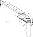
【図1】 本発明に基づく把持具の斜視図である。
【図2】 図1に図示されるのと同じ把持具の構成部分の同様の斜視図である。
【図3】 図2に図示される同じ構成部分の平面図である。
【図4】 図3に図示される構成部分のA−A断面の図である。
【図5】 図1に図示される把持具のB−B断面の図である。
【図6】 図5に図示される把持具のA−A断面の図である。
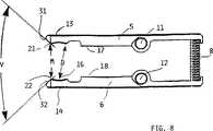
【図7】 図1に図示される把持具のいくつかの構成部分の部分組立の斜視図である。
【図8】 図7に図示する組立の平面図である。[0001]
<Description>
The present invention relates to a gripper that grips a cylinder body in a semi-automatic manner, most effectively holding it securely and releasing it.
[0002]
For the sake of simplicity, the following description refers to a preform of thermoplastic material used in the manufacture of the container, but the invention is not limited to the different claims without departing from the scope of the appended claims. It will be understood that other cylinders used in can of course be applied.
[0003]
Gripping tools for grasping and holding the preform firmly are knownfrom German Utility Model No. 2991310 and French Patent No. 2720679 , which gripping arm, a pair of symmetrical elastically branched members, And a coupling means between the arm and the symmetrical member. The latter is shaped so as to form a recess, and is installed so that the cylindrical portion of the collar of the preform can be inserted into the arms on both sides thereof by simply pressing the collar against the outer portion of the recess, Size is decided. The outer portion is expanded by such a pressing action to an extent appropriate for the preform collar to slide into and hold into the recess.
[0004]
However, such actions, and certain types of grippers that perform such actions, have the following disadvantages.
[0005]
That is, both an axial stress and a lateral stress may be applied to the preform, and in order to withstand such a stress, the symmetric member needs to have a considerable elastic strength.
[0006]
However, it should be taken into account that the degree of elastic strength required causes considerable friction between the arm and the outer surface of the preform, which is made of a thermoplastic material that is only slightly heated. If so, it will be slightly worn. In the case of large-scale continuous production, the above results in the production of very small particles of plastic material, or “flour”, that are needed for production, which adversely affects adjacent parts of the factory and Prevent the regular flow of process operations and make them inaccurate.
[0007]
On the other hand, when such undesirable effects must be reduced, the need arises to reduce the elastic gripping force of the arm. However, such constraints, as is well known to those skilled in the art, cause corresponding inaccuracies in the positioning of the preform, resulting in obvious handling difficulties.
[0008]
On top of that, producing a gripper with a holding arm with high elastic strength means that the production requires much higher accuracy and as a result is even more expensive.
[0009]
Accordingly, one main object of the present invention is to provide a gripping tool for handling cylindrical bodies, in particular plastic preforms, which is free from the aforementioned drawbacks and at the same time is compact and functional. Requires a simple and reliable configuration based on the use of technology that is safe, reliable and easily available.
[0010]
Such a gripper is obtained with the features generally described with particular reference to the appended claims.
[0011]
In any case, the features and advantages of the present invention can be more readily understood from the description set forth below through non-limiting examples with reference to the accompanying drawings.
[0012]
Referring to the drawings, a gripping tool according to the present invention is
-
A
-Connecting means 4 provided between said arm and said plate and firmly joined thereto;
Two symmetrical
A cylindrical spring 8 provided between the tips corresponding to the
[0013]
The
[0014]
However, if it is possible to combine with the appropriate part of the collar of the preform, it is also possible for the opening to have a non-circular shape, instead for example a non-circular arc shape.
[0015]
Furthermore, two
[0016]
The
[0017]
These members are provided with two
[0018]
A cylindrical compression spring 8 is provided at the opposite end of the
[0019]
Said side members are suitable to move at least to a rest position and at least to an action position, the rest position of the spring 8 having a tendency to bring the
[0020]
In this rest position, the
[0021]
That is, a circle whose diameter D is slightly smaller than the diameter H of the semicircular opening 7 is shown.
[0022]
The
[0023]
The working position is illustrated in FIGS. The preform is inserted into the semicircular opening 7, and the
[0024]
The
[0025]
In this manner, the collar of the preform can be released elastically by the combined action of the
[0026]
In fact, by pushing the appropriate part of the collar of the preform axially into the semicircular opening, the side gripping member can be sufficiently separated to an appropriate extent so that the preform can be separated from the semicircular opening. Can be slipped into. When the side gripping member moves to such a position, the spring 8 tries to return to the stationary position of the side gripping member by the action of the spring 8, so that the preform collar is securely held.
In short, according to the present invention, a preform gripping tool having a collar portion is
A handling arm (1);
Adapted to support and handle the preform (3), formed of a plate made of one integral part, preferably provided with a semicircular opening (7) at its tip, the collar of the preform Support means (2) adapted to move to receive and accommodate a portion (28);
Connecting means (4) provided between the arm and the support means and firmly joined thereto;
The two tips (13, 14) are formed with shapes (15, 16) that are movable so as to be matingly coupled to the two parts (15, 16) of the preform collar, and are more elastic. And preferably two symmetrical side parallel gripping members (5, 6) hinged to the plate, adapted to move to a predetermined position.
[0027]
In particular, in such an embodiment, the lateral stress on the preform is easily countered by the resistance of the arm of the semicircular opening 7 and does not affect the ability to hold the preform firmly and effectively. . On the other hand, the axial stress determined by the preform being inserted into and released from the gripper can be limited to any preferred degree by simply adjusting the characteristics of the spring 8 appropriately. Such a connection of 23 does not impair the stability of the preform and in particular the precision of the position where the preform is held.
[0028]
The method by which the preform is inserted can be easily further improved as described below. Two
[0029]
It will be understood that the above description and drawings with reference to the accompanying drawings are merely illustrative of the invention and that numerous variations and modifications may be incorporated without departing from the scope of the claims of the invention.
[Brief description of the drawings]
FIG. 1 is a perspective view of a gripping tool according to the present invention.
FIG. 2 is a similar perspective view of the same gripper component shown in FIG. 1;
FIG. 3 is a plan view of the same components shown in FIG.
4 is a cross-sectional view taken along the line AA of the component shown in FIG. 3;
FIG. 5 is a cross-sectional view of the gripping tool shown in FIG. 1 taken along the line BB.
6 is a cross-sectional view taken along the line AA of the gripping tool illustrated in FIG. 5. FIG.
7 is a perspective view of a partial assembly of several components of the gripper illustrated in FIG. 1. FIG.
8 is a plan view of the assembly shown in FIG.
Claims (5)
Translated fromJapaneseハンドリングアーム(1)と、
プリフォーム(3)の支持と取扱いに適合されており、一つの一体の部品でできたプレートで形成され、その先端には半円形開口部(7)が設けられ前記プリフォームのカラーの一部分(28)と結合すべく移動してそれを収容するのに適合されている支持手段(2)と、
前記アームと前記支持手段との間に設けられてそれらに堅固に接合される連結手段(4)と、
二つの先端(13、14)にはプリフォームのカラーの二つの各部分(15、16)に嵌合的に結合するように移動可能な各形状(15、16)が形成され、更に弾性的に移動して所定の位置まで互いに接近するように適合されている、前記プレートに蝶着されている二つの対称な、平行する側部把持部材(5、6)と、
前記各先端(13、14)の両側の前記二つの側部把持部材に圧縮形態で作用する一以上の弾性部材とを備え、
前記弾性部材は、前記把持部材に作用する円筒バネ(8)を備え、
前記プレートには前記先端と反対の端に前記ばねを収容するための穴(33)が設けられている把持具において、
前記プレートは中央に隆起部(20)を備え、前記側部把持部材はその静止位置にて隆起部の各溝(9、10)に当接することを特徴とするプリフォーム用の把持具。A grip for a preform having a color part,
A handling arm (1);
It is adapted to support and handle the preform (3), is formed of a plate made of one integral part,and has a semicircular opening (7) at its tip,which is a part of the collar of the preform ( 28) support means (2) adapted to move to receive and accommodate it;
Connecting means (4) provided between the arm and the support means and firmly joined thereto;
The two tips (13, 14) are formed with shapes (15, 16) that are movable so as to be matingly coupled to the two parts (15, 16) of the preform collar, and are more elastic. Two symmetrical parallel side gripping members (5, 6) hinged to the plate, adapted to move to each other and to a predetermined position;
One or more elastic members acting in a compressed form on the two side gripping members on both sides of each tip (13, 14);
The elastic member includes a cylindrical spring (8) that acts on thegripping member,
In the gripping tool in which the plate is provided with a hole (33) for accommodating the spring at the end opposite to the tip.
The preform has a raised portion (20) in the center, and the side gripping member abuts against each groove (9, 10) of the raised portion at its stationary position.
Applications Claiming Priority (3)
| Application Number | Priority Date | Filing Date | Title |
|---|---|---|---|
| IT99U000023 | 1999-06-09 | ||
| IT1999PN000023UIT248029Y1 (en) | 1999-06-09 | 1999-06-09 | GRIPPER PERFECTED FOR PREFORM HANDLING |
| PCT/EP2000/003679WO2000076746A1 (en) | 1999-06-09 | 2000-04-25 | Improved grippers for handling preforms |
Publications (2)
| Publication Number | Publication Date |
|---|---|
| JP2003502173A JP2003502173A (en) | 2003-01-21 |
| JP4290364B2true JP4290364B2 (en) | 2009-07-01 |
Family
ID=11395492
Family Applications (1)
| Application Number | Title | Priority Date | Filing Date |
|---|---|---|---|
| JP2001503235AExpired - LifetimeJP4290364B2 (en) | 1999-06-09 | 2000-04-25 | Improved gripper for handling preforms |
Country Status (9)
| Country | Link |
|---|---|
| US (1) | US6612634B1 (en) |
| EP (1) | EP1183146B1 (en) |
| JP (1) | JP4290364B2 (en) |
| AT (1) | ATE228427T1 (en) |
| BR (1) | BR0011374B1 (en) |
| DE (1) | DE60000876T2 (en) |
| ES (1) | ES2187472T3 (en) |
| IT (1) | IT248029Y1 (en) |
| WO (1) | WO2000076746A1 (en) |
Families Citing this family (38)
| Publication number | Priority date | Publication date | Assignee | Title |
|---|---|---|---|---|
| US20050082828A1 (en) | 2003-09-12 | 2005-04-21 | Wicks Jeffrey C. | Releasable connection assembly for joining tubing sections |
| US7448653B2 (en) | 2005-06-10 | 2008-11-11 | Value Plastics, Inc. | Female connector for releasable coupling with a male connector defining a fluid conduit |
| US7806139B2 (en) | 2006-01-20 | 2010-10-05 | Value Plastics, Inc. | Fluid conduit coupling assembly having male and female couplers with integral valves |
| DE102006003142A1 (en) | 2006-01-24 | 2007-08-16 | Sig Technology Ltd. | Device for blow molding containers |
| DE102007011923A1 (en)* | 2007-03-08 | 2008-09-11 | Sig Technology Ag | Device for handling workpieces |
| USD654573S1 (en) | 2007-11-19 | 2012-02-21 | Value Plastics, Inc. | Female quick connect fitting |
| DE102008029711A1 (en)* | 2008-06-24 | 2010-01-07 | Krones Ag | Changeable gripping element for transporting containers |
| USD634840S1 (en) | 2008-07-03 | 2011-03-22 | Value Plastics, Inc. | Female body of connector for fluid tubing |
| US8235426B2 (en) | 2008-07-03 | 2012-08-07 | Nordson Corporation | Latch assembly for joining two conduits |
| USD629894S1 (en) | 2008-07-03 | 2010-12-28 | Value Plastics, Inc. | Male body of connector for fluid tubing |
| USD630320S1 (en) | 2008-07-03 | 2011-01-04 | Value Plastics, Inc. | Connector for fluid tubing |
| USD655393S1 (en) | 2009-06-23 | 2012-03-06 | Value Plastics, Inc. | Multi-port valve |
| USD649240S1 (en) | 2009-12-09 | 2011-11-22 | Value Plastics, Inc. | Male dual lumen bayonet connector |
| US9388929B2 (en) | 2009-12-09 | 2016-07-12 | Nordson Corporation | Male bayonet connector |
| USD650478S1 (en) | 2009-12-23 | 2011-12-13 | Value Plastics, Inc. | Female dual lumen connector |
| USD783815S1 (en) | 2009-12-09 | 2017-04-11 | General Electric Company | Male dual lumen bayonet connector |
| US10711930B2 (en) | 2009-12-09 | 2020-07-14 | Nordson Corporation | Releasable connection assembly |
| JP5814257B2 (en) | 2009-12-23 | 2015-11-17 | ノードソン コーポレーションNordson Corporation | Button latch with integrally molded cantilever spring |
| MY159166A (en) | 2009-12-23 | 2016-12-30 | Nordson Corp | Fluid connector latches with profile lead-ins |
| US8464412B2 (en)* | 2010-01-19 | 2013-06-18 | Cheng Uei Precision Industry Co., Ltd. | Clutching jig |
| US8434206B2 (en)* | 2010-02-03 | 2013-05-07 | Cheng Uei Precision Industry Co., Ltd. | Clutching jig |
| USD652510S1 (en) | 2011-02-11 | 2012-01-17 | Value Plastics, Inc. | Connector for fluid tubing |
| USD652511S1 (en) | 2011-02-11 | 2012-01-17 | Value Plastics, Inc. | Female body of connector for fluid tubing |
| USD663022S1 (en) | 2011-02-11 | 2012-07-03 | Nordson Corporation | Male body of connector for fluid tubing |
| DE102011116883A1 (en)* | 2011-04-21 | 2012-10-25 | Khs Corpoplast Gmbh | Workpiece supporting device for blowing station of container, has tongs that are provided in radial direction of wheel and aligned with centerline of base such that recess of tongs are spanned within range limited in radial direction |
| CH704851A1 (en) | 2011-04-21 | 2012-10-31 | Ferag Ag | Grippers, conveyor system and method for operating such a conveyor system. |
| USD699840S1 (en) | 2011-07-29 | 2014-02-18 | Nordson Corporation | Male body of connector for fluid tubing |
| USD699841S1 (en) | 2011-07-29 | 2014-02-18 | Nordson Corporation | Female body of connector for fluid tubing |
| USD698440S1 (en) | 2011-07-29 | 2014-01-28 | Nordson Corporation | Connector for fluid tubing |
| USD709612S1 (en) | 2011-12-23 | 2014-07-22 | Nordson Corporation | Female dual lumen connector |
| DE102012011367A1 (en)* | 2012-06-11 | 2013-12-12 | Khs Gmbh | hook assembly |
| CH706757A1 (en) | 2012-07-23 | 2014-01-31 | Ferag Ag | Grippers, conveyor system and method for operating such a conveyor system. |
| DE102014218899A1 (en)* | 2014-09-19 | 2016-03-24 | Homag Holzbearbeitungssysteme Gmbh | Gripping device for a machining tool, storage system and method |
| US10166665B2 (en)* | 2016-01-11 | 2019-01-01 | Ford Global Technologies, Llc | Disconnection tool for quick-disconnect couplings |
| USD838366S1 (en) | 2016-10-31 | 2019-01-15 | Nordson Corporation | Blood pressure connector |
| CN113084737B (en)* | 2021-03-30 | 2022-09-30 | 刘昭华 | Wrench device for field operation of nut and using method |
| USD1003725S1 (en) | 2021-09-03 | 2023-11-07 | Graham Packaging Company, L.P. | Container |
| USD1010454S1 (en) | 2021-09-03 | 2024-01-09 | Graham Packaging Company, L.P. | Container |
Family Cites Families (6)
| Publication number | Priority date | Publication date | Assignee | Title |
|---|---|---|---|---|
| DE3717201A1 (en)* | 1987-05-22 | 1988-12-08 | Chiron Werke Gmbh | GRIPPER FOR TOOLS OF A MACHINE TOOL |
| US4858980A (en)* | 1988-08-23 | 1989-08-22 | Cincinnati Milacron Inc. | Article gripper |
| US5102177A (en)* | 1990-06-11 | 1992-04-07 | Cincinnati Milacron Inc. | Article gripper having opposed jaws cammed open by an article |
| DE9111159U1 (en)* | 1991-09-09 | 1991-10-24 | MAHO AG, 8962 Pfronten | Tool gripper |
| FR2720679A1 (en)* | 1994-06-03 | 1995-12-08 | Sidel Sa | Transfer arm and machine for making bottles from a preform using such an arm. |
| DE29713510U1 (en)* | 1997-07-30 | 1998-08-27 | Krones Ag Hermann Kronseder Maschinenfabrik, 93073 Neutraubling | Rotary filler |
- 1999
- 1999-06-09ITIT1999PN000023Upatent/IT248029Y1/enactive
- 2000
- 2000-04-25EPEP00929417Apatent/EP1183146B1/ennot_activeExpired - Lifetime
- 2000-04-25DEDE60000876Tpatent/DE60000876T2/ennot_activeExpired - Lifetime
- 2000-04-25ATAT00929417Tpatent/ATE228427T1/enactive
- 2000-04-25USUS10/009,170patent/US6612634B1/ennot_activeExpired - Lifetime
- 2000-04-25ESES00929417Tpatent/ES2187472T3/ennot_activeExpired - Lifetime
- 2000-04-25BRBRPI0011374-3Apatent/BR0011374B1/ennot_activeIP Right Cessation
- 2000-04-25WOPCT/EP2000/003679patent/WO2000076746A1/enactiveIP Right Grant
- 2000-04-25JPJP2001503235Apatent/JP4290364B2/ennot_activeExpired - Lifetime
Also Published As
| Publication number | Publication date |
|---|---|
| ES2187472T3 (en) | 2003-06-16 |
| BR0011374A (en) | 2002-03-05 |
| EP1183146A1 (en) | 2002-03-06 |
| EP1183146B1 (en) | 2002-11-27 |
| DE60000876D1 (en) | 2003-01-09 |
| US6612634B1 (en) | 2003-09-02 |
| ATE228427T1 (en) | 2002-12-15 |
| JP2003502173A (en) | 2003-01-21 |
| WO2000076746A1 (en) | 2000-12-21 |
| ITPN990023V0 (en) | 1999-06-09 |
| ITPN990023U1 (en) | 2000-12-09 |
| DE60000876T2 (en) | 2003-05-28 |
| IT248029Y1 (en) | 2002-12-09 |
| BR0011374B1 (en) | 2010-02-09 |
Similar Documents
| Publication | Publication Date | Title |
|---|---|---|
| JP4290364B2 (en) | Improved gripper for handling preforms | |
| US4813107A (en) | Spring clamp | |
| KR100449314B1 (en) | Plastic clamp | |
| EP1201371A3 (en) | Press tool | |
| ATE387889T1 (en) | GRIPPERS | |
| US6012362A (en) | Utility pliers | |
| GB2334913A (en) | Self adjusting pliers | |
| US8864775B2 (en) | Applying forceps for a clip | |
| US20120000326A1 (en) | Parallel action pliers | |
| US20030131647A1 (en) | Ergonomic crimping apparatus | |
| US4919017A (en) | Hose clamp tool | |
| CN101365561B (en) | Clamp, attachment for the clamp and method of manufacturing the clamp | |
| WO2001073330A3 (en) | Fitting for pressure coupling plastics pipes | |
| US7437978B1 (en) | Self-adjusting locking vise grip | |
| US20230278171A1 (en) | Alignment jig and holding system for a workpiece | |
| CN205342961U (en) | Trachea quick -insertion structure's special plug instrument | |
| CN201002220Y (en) | Adjustable Pliers | |
| CN113799166A (en) | Industrial robot composite clamp | |
| JP3241325U (en) | E-shaped retaining ring insertion tool | |
| CN219275592U (en) | Clamp adjusting structure | |
| CN218747159U (en) | Circlip pliers | |
| CN218254971U (en) | Novel jump ring pincers | |
| KR200390312Y1 (en) | A wrench adjustable handle | |
| JP2011097785A (en) | Plier for remote control | |
| US20050034574A1 (en) | Hand tool having an extendable handle structure |
Legal Events
| Date | Code | Title | Description |
|---|---|---|---|
| RD04 | Notification of resignation of power of attorney | Free format text:JAPANESE INTERMEDIATE CODE: A7424 Effective date:20040922 | |
| A621 | Written request for application examination | Free format text:JAPANESE INTERMEDIATE CODE: A621 Effective date:20061124 | |
| A131 | Notification of reasons for refusal | Free format text:JAPANESE INTERMEDIATE CODE: A131 Effective date:20081104 | |
| A521 | Request for written amendment filed | Free format text:JAPANESE INTERMEDIATE CODE: A523 Effective date:20090203 | |
| TRDD | Decision of grant or rejection written | ||
| A01 | Written decision to grant a patent or to grant a registration (utility model) | Free format text:JAPANESE INTERMEDIATE CODE: A01 Effective date:20090310 | |
| A01 | Written decision to grant a patent or to grant a registration (utility model) | Free format text:JAPANESE INTERMEDIATE CODE: A01 | |
| A61 | First payment of annual fees (during grant procedure) | Free format text:JAPANESE INTERMEDIATE CODE: A61 Effective date:20090401 | |
| R150 | Certificate of patent or registration of utility model | Ref document number:4290364 Country of ref document:JP Free format text:JAPANESE INTERMEDIATE CODE: R150 Free format text:JAPANESE INTERMEDIATE CODE: R150 | |
| FPAY | Renewal fee payment (event date is renewal date of database) | Free format text:PAYMENT UNTIL: 20120410 Year of fee payment:3 | |
| FPAY | Renewal fee payment (event date is renewal date of database) | Free format text:PAYMENT UNTIL: 20130410 Year of fee payment:4 | |
| R250 | Receipt of annual fees | Free format text:JAPANESE INTERMEDIATE CODE: R250 | |
| FPAY | Renewal fee payment (event date is renewal date of database) | Free format text:PAYMENT UNTIL: 20140410 Year of fee payment:5 | |
| R250 | Receipt of annual fees | Free format text:JAPANESE INTERMEDIATE CODE: R250 | |
| R250 | Receipt of annual fees | Free format text:JAPANESE INTERMEDIATE CODE: R250 | |
| R250 | Receipt of annual fees | Free format text:JAPANESE INTERMEDIATE CODE: R250 | |
| R250 | Receipt of annual fees | Free format text:JAPANESE INTERMEDIATE CODE: R250 | |
| R250 | Receipt of annual fees | Free format text:JAPANESE INTERMEDIATE CODE: R250 | |
| R250 | Receipt of annual fees | Free format text:JAPANESE INTERMEDIATE CODE: R250 | |
| R250 | Receipt of annual fees | Free format text:JAPANESE INTERMEDIATE CODE: R250 | |
| R250 | Receipt of annual fees | Free format text:JAPANESE INTERMEDIATE CODE: R250 | |
| EXPY | Cancellation because of completion of term |