JP4288504B2 - Shift lever mechanism - Google Patents
Shift lever mechanismDownload PDFInfo
- Publication number
- JP4288504B2 JP4288504B2JP2004518953AJP2004518953AJP4288504B2JP 4288504 B2JP4288504 B2JP 4288504B2JP 2004518953 AJP2004518953 AJP 2004518953AJP 2004518953 AJP2004518953 AJP 2004518953AJP 4288504 B2JP4288504 B2JP 4288504B2
- Authority
- JP
- Japan
- Prior art keywords
- lever
- biasing
- disposed
- neutral position
- shift lever
- Prior art date
- Legal status (The legal status is an assumption and is not a legal conclusion. Google has not performed a legal analysis and makes no representation as to the accuracy of the status listed.)
- Expired - Fee Related
Links
- 230000007935neutral effectEffects0.000claimsdescription27
- 230000005540biological transmissionEffects0.000description11
- 238000006073displacement reactionMethods0.000description10
- 238000004519manufacturing processMethods0.000description6
- 239000000463materialSubstances0.000description3
- 239000007769metal materialSubstances0.000description3
- 230000000712assemblyEffects0.000description2
- 238000000429assemblyMethods0.000description2
- 238000006243chemical reactionMethods0.000description2
- 230000000007visual effectEffects0.000description1
Images


Classifications
- F—MECHANICAL ENGINEERING; LIGHTING; HEATING; WEAPONS; BLASTING
- F16—ENGINEERING ELEMENTS AND UNITS; GENERAL MEASURES FOR PRODUCING AND MAINTAINING EFFECTIVE FUNCTIONING OF MACHINES OR INSTALLATIONS; THERMAL INSULATION IN GENERAL
- F16H—GEARING
- F16H59/00—Control inputs to control units of change-speed- or reversing-gearings for conveying rotary motion
- F16H59/02—Selector apparatus
- F16H59/04—Ratio selector apparatus
- F—MECHANICAL ENGINEERING; LIGHTING; HEATING; WEAPONS; BLASTING
- F16—ENGINEERING ELEMENTS AND UNITS; GENERAL MEASURES FOR PRODUCING AND MAINTAINING EFFECTIVE FUNCTIONING OF MACHINES OR INSTALLATIONS; THERMAL INSULATION IN GENERAL
- F16H—GEARING
- F16H59/00—Control inputs to control units of change-speed- or reversing-gearings for conveying rotary motion
- F16H59/02—Selector apparatus
- F16H2059/026—Details or special features of the selector casing or lever support
- F16H2059/0269—Ball joints or spherical bearings for supporting the lever
- F—MECHANICAL ENGINEERING; LIGHTING; HEATING; WEAPONS; BLASTING
- F16—ENGINEERING ELEMENTS AND UNITS; GENERAL MEASURES FOR PRODUCING AND MAINTAINING EFFECTIVE FUNCTIONING OF MACHINES OR INSTALLATIONS; THERMAL INSULATION IN GENERAL
- F16H—GEARING
- F16H59/00—Control inputs to control units of change-speed- or reversing-gearings for conveying rotary motion
- F16H59/02—Selector apparatus
- F16H2059/0295—Selector apparatus with mechanisms to return lever to neutral or datum position, e.g. by return springs
- G—PHYSICS
- G05—CONTROLLING; REGULATING
- G05G—CONTROL DEVICES OR SYSTEMS INSOFAR AS CHARACTERISED BY MECHANICAL FEATURES ONLY
- G05G9/00—Manually-actuated control mechanisms provided with one single controlling member co-operating with two or more controlled members, e.g. selectively, simultaneously
- G05G9/02—Manually-actuated control mechanisms provided with one single controlling member co-operating with two or more controlled members, e.g. selectively, simultaneously the controlling member being movable in different independent ways, movement in each individual way actuating one controlled member only
- G05G9/04—Manually-actuated control mechanisms provided with one single controlling member co-operating with two or more controlled members, e.g. selectively, simultaneously the controlling member being movable in different independent ways, movement in each individual way actuating one controlled member only in which movement in two or more ways can occur simultaneously
- G05G9/047—Manually-actuated control mechanisms provided with one single controlling member co-operating with two or more controlled members, e.g. selectively, simultaneously the controlling member being movable in different independent ways, movement in each individual way actuating one controlled member only in which movement in two or more ways can occur simultaneously the controlling member being movable by hand about orthogonal axes, e.g. joysticks
- G05G2009/04703—Mounting of controlling member
- G05G2009/04733—Mounting of controlling member with a joint having a nutating disc, e.g. forced by a spring
- Y—GENERAL TAGGING OF NEW TECHNOLOGICAL DEVELOPMENTS; GENERAL TAGGING OF CROSS-SECTIONAL TECHNOLOGIES SPANNING OVER SEVERAL SECTIONS OF THE IPC; TECHNICAL SUBJECTS COVERED BY FORMER USPC CROSS-REFERENCE ART COLLECTIONS [XRACs] AND DIGESTS
- Y10—TECHNICAL SUBJECTS COVERED BY FORMER USPC
- Y10T—TECHNICAL SUBJECTS COVERED BY FORMER US CLASSIFICATION
- Y10T74/00—Machine element or mechanism
- Y10T74/20—Control lever and linkage systems
- Y10T74/20012—Multiple controlled elements
- Y10T74/20018—Transmission control
- Y10T74/2014—Manually operated selector [e.g., remotely controlled device, lever, push button, rotary dial, etc.]
- Y10T74/20159—Control lever movable through plural planes
- Y10T74/20165—Spherical mount [e.g., ball and socket]
Landscapes
- Engineering & Computer Science (AREA)
- General Engineering & Computer Science (AREA)
- Mechanical Engineering (AREA)
- Arrangement Or Mounting Of Control Devices For Change-Speed Gearing (AREA)
- Control Of Transmission Device (AREA)
- Transition And Organic Metals Composition Catalysts For Addition Polymerization (AREA)
- Lock And Its Accessories (AREA)
- Valve-Gear Or Valve Arrangements (AREA)
- Gear-Shifting Mechanisms (AREA)
Abstract
Description
Translated fromJapanese本発明は、ギヤシフトレバー機構に関し、特にシフトレバーを支持し、また、シフトレバーを好ましい位置へ付勢することに関する。 The present invention relates to a gear shift lever mechanism, and more particularly to supporting a shift lever and biasing the shift lever to a preferred position.
通常、変速システムにおける変速比のシフトは、変速機の1組の変速フォークを作動させるシフトフィンガによって実行される。シフトフィンガは、変速機の外へ延びて支持機構で支持されるシフトレバーによって作動される。 Normally, shifting of the transmission ratio in a transmission system is performed by a shift finger that operates a set of transmission forks in the transmission. The shift finger is operated by a shift lever that extends out of the transmission and is supported by a support mechanism.
後輪駆動の車両では、しばしば、シフトレバーは、変速システム上で直接的に操作可能であり、その上部から延びるハウジングに取付けられている。前輪駆動の車両及び後輪駆動の車両のいくつかの場合では、運転席に対する変速機の配置によって、シフトレバーは、通常、リモートコントロールシフトアセンブリによって、変速機を遠隔的に作動させる。リモートコントロールシフトアセンブリは、通常、一連のレバー、あるいは、例えばケーブル又は油圧機構等のシフトレバーに連結される他の手段を備えている。 In rear-wheel drive vehicles, the shift lever is often directly operable on the transmission system and is attached to a housing extending from the top thereof. In some cases of front-wheel drive vehicles and rear-wheel drive vehicles, the shift lever is typically remotely actuated by a remote control shift assembly, depending on the location of the transmission relative to the driver's seat. Remote control shift assemblies typically include a series of levers or other means coupled to a shift lever, such as a cable or hydraulic mechanism.
公知のシフトレバー支持機構は、シフトレバー上に配置される拡径された球状部分を備えている。球状部分は、その機構の保持カップ内に配置されて、球体どうしの係合を介して、その中でピボット動作して、シフト動作を実行する。保持カップは、レバーが挿通されるハウジングの中に収容されている。 A known shift lever support mechanism includes a spherical portion having an enlarged diameter disposed on the shift lever. The bulbous part is placed in the holding cup of the mechanism and pivots in it through the engagement of the spheres to perform the shifting action. The holding cup is accommodated in a housing through which the lever is inserted.
また、シフトレバー機構は、一般的に、シフトレバーが所定のニュートラル位置からシフトされたとき、シフトレバーに付勢力を付与するように作動する付勢手段を備えている。公知の付勢手段は、一般的に、レバーの反対側に接触する直径方向両側の一対のリターンピンを備えている。これらのリターンピンは、付勢されたニュートラル位置にあるレバーを横切る軸に沿って配置されて、レバーの側面の下部領域に付勢力を付与するように作動する。通常、それぞれの側面と関連するリターンピンとの間には、製造公差による隙間がある。 The shift lever mechanism generally includes a biasing means that operates to apply a biasing force to the shift lever when the shift lever is shifted from a predetermined neutral position. Known biasing means generally includes a pair of diametric return pins that contact the opposite side of the lever. These return pins are arranged along an axis that traverses the lever in the biased neutral position and operate to apply a biasing force to the lower region of the side of the lever. There is typically a manufacturing tolerance gap between each side and the associated return pin.
使用中、レバーのニュートラル位置からのピボット変位は、これを関連するリターンピンに当接させ、レバーの更なる変位は、ばねの付勢力に抗してリターンピンを変位させ、これにより、レバーをニュートラル位置へ戻す戻し力がレバーに作用する。 In use, a pivot displacement from the neutral position of the lever causes it to abut the associated return pin, and further displacement of the lever displaces the return pin against the biasing force of the spring, thereby A return force to return to the neutral position acts on the lever.
上述の公知の機構は、レバーの変位に対する方向の配置が制限されたリターンピンの形式により、付勢手段によって、レバーが望ましくない運動を行う。レバーを完全に付勢するため、レバーが変位可能なそれぞれの方向にピンを配置する必要がある。このことは、それぞれのリターンピンは、それが配置されるハウジングに機械加工された穴を必要とするので、経済的でないのは明らかである。 In the known mechanism described above, the lever moves undesirably by the biasing means in the form of a return pin with a limited orientation in the direction of the lever displacement. In order to fully bias the lever, it is necessary to place a pin in each direction in which the lever can be displaced. This is clearly not economical as each return pin requires a machined hole in the housing in which it is placed.
更に、レバーのそれぞれの側面と関連するリターンピンとの間の隙間は、レバーの望ましくない運動に転換され、これは使用者によって感じとられる。 In addition, the gap between each side of the lever and the associated return pin translates into an undesirable movement of the lever, which is felt by the user.
更に、リターンピンの配置は、ハウジングの縦軸を横切り、所望の付勢力を付与するためにピンが必要とする移動距離は、当該機構の最少全幅を規定する。
特許文献1は、ピボット手段に取付けられたギヤシフトレバーを開示している。このピボット手段は、2つの部分からなるボールと、カム機構と、協働するソケットに接触するボールの2つの部分を支持するように作動するスプリングとを備えている。カム機構は、一の位置にあるギヤシフトレバーを支持するようにボールを介して作用する。
しかしながら、このシフトレバー機構は、レバーが横方向の一平面でのみ付勢されること及び付勢するカム機構がボールの中に配置されていることで不利を被っている。このため、このシフトレバー機構の横方向の寸法は、この機構の縦軸から径方向外側へ延びるその要素によって規程される。更に、このシフトレバー機構は、付勢機構がピボット手段の中に配置されていることにより、比較的製造が複雑になっている。
Patent Document 1 discloses a gear shift lever attached to a pivot means. The pivot means includes a two-part ball, a cam mechanism, and a spring that operates to support the two parts of the ball that contact the cooperating socket. The cam mechanism acts via the ball to support the gear shift lever in one position.
However, this shift lever mechanism suffers from the disadvantage that the lever is urged only in one lateral plane and the urging cam mechanism is arranged in the ball. For this reason, the lateral dimension of the shift lever mechanism is defined by its elements extending radially outward from the longitudinal axis of the mechanism. Further, this shift lever mechanism is relatively complicated to manufacture because the biasing mechanism is disposed in the pivot means.
レバーがニュートラル位置を含む所定の位置へ変位されたとき、明確な感覚及び位置の確実性が使用者にわかることが望ましい。更に、シフトレバー機構の機能の効率を増大させ、また、その製造コストを減少させることが望ましい。 It is desirable for the user to know a clear sense and position certainty when the lever is displaced to a predetermined position, including the neutral position. Furthermore, it is desirable to increase the efficiency of the function of the shift lever mechanism and reduce its manufacturing cost.
更に、その寸法がハウジングの縦軸から径方向外側へ延びる要素によって左右されないコンパクトな機構が望まれる。 Furthermore, a compact mechanism is desired whose dimensions are not affected by elements extending radially outward from the longitudinal axis of the housing.
本発明の1つの目的は、明確な感覚及びレバー位置の確実性を使用者に与えるように作動するシフトレバー機構を提供することである。 One object of the present invention is to provide a shift lever mechanism that operates to provide a clear sense and lever position certainty to the user.
また、機能的な効率が増大されたシフトレバー機構を提供することも本発明の目的である。 It is also an object of the present invention to provide a shift lever mechanism with increased functional efficiency.
更に、比較的低い製造コストのシフトレバー機構を提供することが本発明の目的である。 Furthermore, it is an object of the present invention to provide a shift lever mechanism with a relatively low manufacturing cost.
更に、本発明の目的は、ハウジングの縦軸から径方向に延びる要素によって寸法が左右されないコンパクトなシフトレバー機構を提供することである。 It is a further object of the present invention to provide a compact shift lever mechanism whose dimensions are not affected by elements extending radially from the longitudinal axis of the housing.
本発明によれば、シフトレバー機構は、レバーと、該レバーをニュートラル位置から複数のピボット動作されたギヤ選択位置へピボット動作できるようにするピボット手段と、前記レバー上にこれと同軸に配置されて、該レバーを前記ニュートラル位置へ付勢するように作動する付勢手段とを備え、
前記付勢手段は、支持表面を有する第1要素と、前記レバーと同軸に配置され、端部表面及び付勢表面を有する第2要素と、前記レバー上に配置され、これに固定されて、そこから径方向外側へ延びる第3要素と、前記レバーと同軸に配置されて、前記付勢表面と前記第3要素との間に延びるように配置された付勢要素とを備え、
前記レバーがニュートラル位置からギヤ選択位置へピボット動作したとき、前記第2要素の端部表面が前記第1要素の支持表面を押圧して、スプリング及び前記第3要素を介して、前記レバーに付与される戻し付勢力を生じさせ、これにより、前記レバーをニュートラル位置へ付勢する。
付勢手段は、レバーと同軸になるように配置することができる。
前記付勢要素は、スプリングとすることができる。In accordance with the present invention, the shift lever mechanism is disposed on and coaxially with the lever, pivot means for enabling the lever to pivot from a neutral position to a plurality of pivoted gear selection positions. Biasing means that actuates the lever to the neutral position,
The biasing means is disposed on and secured to a first element having a support surface, a second element disposed coaxially with the lever, having an end surface and a biasing surface, A third element extending radially outward therefrom, and a biasing element disposed coaxially with the lever and disposed between the biasing surface and the third element;
When the lever pivots from the neutral position to the gear selection position, the end surface of the second element presses the support surface of the first element and is applied to the lever via the spring and the third element A return biasing force is generated, thereby biasing the lever to the neutral position.
The biasing means can be arranged so as to be coaxial with the lever.
The biasing element may be a spring.
このシフトレバー機構は、ハウジングと、縦軸を有するレバーと、レバーを複数の位置へピボット動作できるようにするピボット手段と、レバーを少なくとも1つの付勢された位置へ付勢する付勢手段とを備え、付勢手段は、レバーの縦軸に対して、ほぼ横切らない方向に付勢力を付与するように作動するようにすることができる。The shift lever mechanism includes a housing, a lever having a longitudinal axis, pivot means for enabling the lever to pivot to a plurality of positions, and biasing means for biasing the lever to at least one biased position. And the biasing meanscan be operated to apply a biasing force in a direction that does not substantially cross the longitudinal axis of the lever.
このシフトレバー機構は、ハウジングと、縦軸を有するレバーと、レバーを複数の位置へピボット動作できるようにするピボット手段と、レバーを少なくとも1つの付勢された位置へ付勢する付勢手段とを備え、付勢手段は、レバーが変位可能な任意の方向に対抗するように付勢力を付与するようすることができる。The shift lever mechanism includes a housing, a lever having a longitudinal axis, pivot means for enabling the lever to pivot to a plurality of positions, and biasing means for biasing the lever to at least one biased position. And the biasing meanscan apply a biasing force so as to oppose any direction in which the lever can be displaced.
ハウジングは、縦軸を有することができ、付与される付勢力の方向がほぼハウジングの縦軸のとなっている。付勢された位置にあるとき、縦軸は、付勢力が付与される方向とほぼ同じ方向にある。The housingcan have a longitudinal axis, and the direction of the applied biasing force is approximately the longitudinal axis of the housing. When in the biased position, the vertical axis is in substantially the same direction as the direction in which the biasing force is applied.
レバーは、好ましくは、第1要素、第2要素及び付勢要素を貫通して延びて、これらとほぼ同軸に配置されている。付勢要素は、スプリングを含むことができる。 The lever preferably extends through the first element, the second element and the biasing element and is arranged substantially coaxially therewith. The biasing element can include a spring.
第1要素は、好ましくは、ストップ手段と係合するようになっており、このストップ手段は、好ましくはハウジング上に配置され、更に好ましくはハウジングの内壁に配置される。ストップ手段は、ハウジングの内壁の縮径された領域を含むことができ、これが第1要素と係合する当接部を形成する。 The first element is preferably adapted to engage stop means, which is preferably arranged on the housing, more preferably on the inner wall of the housing. The stop means can include a reduced diameter region of the inner wall of the housing, which forms an abutment that engages the first element.
ストップ手段は、第1部材の少なくとも一方へのピボット変位を阻止するように作動する。 The stop means operates to prevent pivot displacement to at least one of the first members.
あるいは、ストップ手段は、レバーに配置され、又は、連動する変速システムの内部に配置されてもよい。 Alternatively, the stop means may be disposed in the lever or disposed in the interlocking transmission system.
シフトレバー機構は、また、第1付勢手段と同様の第2付勢手段を備えてもよい。
ピボット手段は、レバーの第1及び第2付勢手段の中間に配置することができる。The shift lever mechanism may also include second urging means similar to the first urging means.
The pivot means can be located intermediate the first and second biasing means of the lever.
ピボット手段は、好ましくは保持カップ内に配置された球状要素を備え、これらの球体どうしの係合によってピボット動作するように作動する。The pivoting means preferably comprises a spherical element arranged in the holding cup and operates to pivot by the engagement of these spheres.
球状要素は、レバーに固定され、これにより、レバー上にピボット点を形成する。球状要素は、保持ピンによってレバーに固定することができる。あるいは、球状要素は、レバーの一体部分を形成してもよい。 The spherical element is fixed to the lever, thereby forming a pivot point on the lever. The spherical element can be fixed to the lever by a holding pin. Alternatively, the spherical element may form an integral part of the lever.
レバーは、球状要素を貫通して延びて、これらとほぼ同軸に配置することができる。
球状要素は、好ましくは、レバーの第1端部と第2端部との中間に配置される。The lever can extend through the spherical elements and be arranged substantially coaxially therewith.
The spherical element is preferably arranged midway between the first end and the second end of the lever.
球状要素は、好ましくは、プラスチック材料で形成される。あるいは、球状要素は、金属材料で形成されてもよい。 The spherical element is preferably formed of a plastic material. Alternatively, the spherical element may be formed of a metallic material.
保持カップは、プラスチック材料で形成することができる。あるいは、保持カップは、金属材料で形成されてもよい。 The retaining cup can be formed of a plastic material. Alternatively, the holding cup may be formed of a metal material.
保持カップは、ハウジング内に配置され、また、1つ以上の部分から形成されてもよい。 The retaining cup is disposed within the housing and may be formed from one or more parts.
本発明は、更に、例示として、添付の図面を参照して説明される。
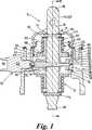
図面を参照すると、縦軸14を有するハウジング12と、第1端部18、第2端部20及び縦軸22を有するレバー16と、ピボット手段24と、付勢手段26とを備えたシフトレバー機構10が示されている。The invention is further described, by way of example, with reference to the accompanying drawings.
Referring to the drawings, a shift lever comprising a
ハウジング12は、軸14の回りに円筒状に形成され、内面30を有する壁部28及びカバー32を備えている。 The
レバー16は、外径を有する細長い部材から形成され、ニュートラル位置において、ハウジング12の中に、その縦軸14に沿って配置されている。 The
ピボット手段24は、外側球面36を有する球状要素34及び内側球面40を有する保持カップ38を備えている。保持カップ38は、その中に球状要素34を保持して、球状要素34の外側球面36と保持カップ38の内側球面40との係合によって、球状要素34のピボット点42回りのピボット変位を行うように作動する。 The pivot means 24 comprises a
保持カップ38は、この機構の組立を容易にする2つ又はそれ以上の部分から形成することができる。 The retaining
球状要素34及び保持カップ38は、プラスチック材料から形成することができる。あるいは、これらは、金属材料から形成することができる。 The
レバー16は、その第1端部18と第2端部20との中間が球状要素34を貫通して延びて、保持ピン44によって、これに固定されている。レバー16は、これにより、ピボット点42回りでピボット運動することができる。 The
付勢手段26は、レバー16の縦軸22に沿って変位可能な第1要素46及び第2要素48と、レバー16に対して固定された第3要素50と、第2要素48と第3要素50との中間に配置されたスプリング52の形の付勢要素とを備えている。 The biasing means 26 includes a
また、付勢手段26は、当接部56として、ハウジング壁部28の内面30に配置された縮径領域の形でストップ手段54を備えている。当接部56は、保持カップ38の一部を形成して、製造コストを減少させることができる。 Further, the biasing means 26 includes a stop means 54 as a
第1要素46は、ハウジング12の中で、その縦軸14の方向に変位するために充分小さく、ハウジング壁部28の内面30に配置された当接部56に当接するのに充分大きい外径を有する環状のディスクの形をとっている。また、第1要素46は、支持表面47及び軸方向反対側の当接表面49を備えている。第1要素46は、また、これを軸方向に貫通して延びる開口58を備えている。 The
第2要素48は、上端部62へ延びる小外径領域60及び縁取り端部66を形成する大外径領域64を有するシルクハット状のブッシュの形をとっている。縁取り端部66は、縁取り端部表面67及び付勢表面69を備えている。第2要素48は、また、これを貫通して軸方向に延びる開口68を備えている。 The
第3要素50は、これを貫通して軸方向に延びる開口70を有する環状ディスクの形をとっている。 The
組立てられた状態で、レバー16は、第1要素46の開口58を貫通して延びている。開口58の直径は、レバー16がこれを横切らない位置に配置できるように、レバー16の外径よりも充分大きい。 In the assembled state, the
レバー16は、更に、第2要素48の開口68を貫通して延びている。開口68の直径は、第2要素48がレバー16の外表面上をその縦軸22に沿って摺動できるように、レバー16の外径よりも大きい。 The
第2要素の縁取り端部66は、縁取り端部表面67が第1要素46の支持表面47に当接するように配置されている。 The
レバー16は、更に、第3要素50に配置された開口70を貫通して延びるている。レバー16は、その外周回りに配置された縮径領域によって形成される溝71を備えている。開口70は、第3要素50が溝71内へ延びるように、外径がレバー16の外表面の直径よりも小さく、これにより、第3要素50をレバー16に対して縦軸方向に固定する。 The
スプリング52は、第2要素48の縮径領域60の周囲に配置されて、縁取り端部66の付勢表面69との当接部から第3要素50との当接部へ延びている。The
上述のピボット及び付勢アセンブリは、レバー16の第1端部18及び第2端部20の領域にそれぞれ配置された保持ピン74及び76によって、ハウジングの中に保持されている。レバー16は、更に、ユーザーインターフェイスとして、第1端部18を越えて延び、また、変速システムとの係合のために第2端部20を越えて延びている。 The pivot and biasing assembly described above is held in the housing by holding
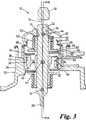
図に示されるように、レバー16の付勢は、レバー16の上述した第1付勢手段26の反対側に配置された第2付勢手段72によって最適化され、ピボット手段24は、レバー16の第1付勢手段26と第2付勢手段72との中間に配置されており、これにより、付勢力に応答するレバー16の反力及びバランスを改善する。 As shown in the figure, the biasing of the
第2付勢手段72は、第1付勢手段26と同様の部品及び同様のアセンブリを備えている。 The second biasing means 72 includes the same components and the same assembly as the first biasing means 26.
図1及び図2は、ニュートラル位置にある使用中のレバーを示し、それぞれの第1要素46は、レバー16の縦軸22にほぼ垂直であり、これにより、それぞれのスプリング52が、レバー16をそのニュートラル位置で支持及びバランスするように延ばされている。 FIGS. 1 and 2 show the lever in use in the neutral position, each
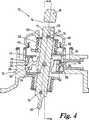
図3及び図4は、断面線B−Bによって規定される第1平面に沿って、ピボット動作されて、所定のギヤ選択位置へ向って変位及び配置された使用中のレバー16を示しており、また、図5は、断面線A−Aによって規定される第2平面に沿ってピボット動作された所定のギヤ選択位置に配置された使用中のレバー16を示し、第2平面は、第1平面をほぼ横断する。 3 and 4 show the
図3及び図4を参照して、第1要素46は、ハウジング12の縦軸14に対して軸方向に固定されて、第2要素48と係合するように作動する支持プラットホームを形成する。 With reference to FIGS. 3 and 4, the
使用中、第3要素50は、レバー16に対して軸方向に固定され、レバー16がピボット変位したとき、レバー16がピボット動作された方向に隣接するスプリング52の領域に力を付与する。付与された力は、第3要素50と第2要素48の付勢表面69との間のスプリング52を圧縮する。第2要素48は、レバー16に沿って摺動可能で、レバーのピボット動作を許容する。しかしながら、ピボット動作が大きくなり、これを第1要素46に向って付勢する力が大きくなると、これらの係合によってそれ以上の移動が阻止される。 In use, the
このため、第2要素の縁取り端部表面67は、第1要素の支持表面47を押圧して、スプリング52及び第3要素50を介してレバー16に作用される戻し付勢力を生じさせ、これにより、レバー16をニュートラル位置へ付勢する。この戻し付勢力は、第2要素48がレバー16の縦軸に沿って摺動可能であることによって増大される。 For this reason, the
同時に、第3要素50は、レバー16がピボット動作される方向に隣接するスプリング52を圧縮する力を付与したとき、協働する伸長力をスプリング52の圧縮力とは径方向反対側に付与し、この伸長力もまた、レバー16をニュートラル位置へ付勢するように作用する。At the same time, the
また、同時に、第2付勢手段は、上述の第1付勢手段と同様に作動して、レバー16への付勢作用の反力及びバランスを最適化する。 At the same time, the second urging means operates in the same manner as the first urging means described above to optimize the reaction force and balance of the urging action on the
図1及び図5を参照して、シフトレバー機構10は、また、ニュートラル位置にあるレバー16の配置を表示するように作動するレバー位置表示手段78を備えている。 Referring to FIGS. 1 and 5, the
レバー位置表示手段78は、レバー16がニュートラル位置に配置されたとき、スイッチ作動手段82に係合して電気的信号を形成するように作動するスイッチ80を備えている。 The lever position indicating means 78 includes a
スイッチ80は、接続端部84及び接触端部86を備え、球状要素34から径方向外側へ延びる軸に沿ってハウジング12の壁部28に配置されている。このスイッチ80は、これが配置された軸に沿って変位可能であり、また、球状要素34へ向って付勢されて、接触端部86が球状要素34に接触する。接続端部84は、例えば視覚的又は聴覚的表示器等のユーザーインターフェイスに接続される。 The
スイッチ作動手段82は、スイッチ80の接触端部86に配置された部材88及び球状要素34に配置された部材受け90を備えている。部材88は、図5に示されるように、レバー16が所定の位置へ変位されたとき、球状要素34の表面に乗り上げるように適当に形成されている。部材受け90は、図1に示されるように、レバー16がニュートラル位置に配置されたとき、部材受け90が部材88に整合して、これをその中に受入れ、これにより、スイッチ80の中で電気的な接続が形成されるように、適当に配置されている。この電気的な接続は、電気的な信号を形成し、この電気的な信号がユーザーインターフェイスを作動させ、これによって、レバー16がニュートラル位置にあることを表示する。後退ライトスイッチ又は他の後退ギヤ警告手段を設けるため、レバー16が後退ギヤ位置へ移動されたとき作動するように、スイッチ機構を適応及び配置することができる。Switch operating means 82 is provided with a contacttouch end 86 disposed
図2から図4を参照して、シフトレバー機構10は、また、例えば変速機を後退ギヤへシフトする位置等の制限された位置へのレバー16の変位に対して抵抗を付与するように作動する弾性手段を備えている。 With reference to FIGS. 2-4, the
図2から図4は、レバー16の制限された位置への漸進的な変位を示している。 2 to 4 show the gradual displacement of the
弾性手段は、弾性部材94及びディテント96を備えている。 The elastic means includes an elastic member 94 and a
弾性部材94は、球状要素34から径方向外側へ延びる軸に沿って、ハウジング12の壁部28に配置されている。弾性部材94は、それが配置された軸に沿って変位可能であり、また、それが球状要素34に接触するように、球状要素34へ向って付勢されている。弾性部材94は、レバー16が他の位置に配置されたとき、球状要素34の表面に乗り上げ、また、レバー16の制限された位置への変位中に、ディテント96に係合するように適当に形成された接触端部98を有している。 The elastic member 94 is disposed on the
ディテント96は、レバー16の制限された位置への変位が試みられたときだけ、弾性部材94に係合するように、球状要素34上に適当に配置されている。 The
使用中に、レバー16の制限された位置へ変位が試みられると、弾性部材94がディテント96に係合し、このディテント96がレバー16の制限された位置の方向への更なる変位に対する抵抗力を付与する。レバー16に付与される制限された位置の方向への力が増大して、弾性部材94に付与される付勢に打勝つのに充分になると、弾性部材94がディテント96に乗り上げることができ、これにより、レバー16が制限された位置へ配置できるようになる。 In use, when an attempt is made to displace the
本構造は、非常にコンパクトなシフトレバーアセンブリの製造を可能にすることが、この説明から分るであろう。これは、公知の装置と比較したとき、変速機の上方の高さを減少させることができ、また、大きな球状のピボット要素が不要となり、レバー上にコンパクトな付勢手段が配置されることにより、更なる小型化を可能にする。 It will be appreciated from this description that this structure allows for the production of very compact shift lever assemblies. This can reduce the height above the transmission when compared to known devices, eliminates the need for large spherical pivot elements, and places a compact biasing means on the lever. , Enabling further miniaturization.
本アセンブリは、1つの付勢手段26で作動可能であるが、球状要素34によって形成される上述の1つのピボット軸及び1つの下方の第2付勢手段72を有することが望ましい。これは、シフト操作のよりバランスされた感覚を提供し、また、アセンブリの設計及び構造の更なる簡単化を促進する。 The assembly is operable with one biasing means 26, but preferably has one pivot shaft as described above formed by the
本明細書の説明及び請求の範囲を通して、「備える」という語、及び、例えば「備えている」等のそれが変異した語は、「含んでいるが限定されない」という意味であって、他の部品又は完成品を除外することを意図するものではない。 Throughout the description and claims of this specification, the word “comprising” and its mutated words such as “comprising” mean “including but not limited to” It is not intended to exclude parts or finished products.
Claims (6)
Translated fromJapanese前記第1付勢手段(26)は、支持表面(47)を有する環状のディスクの形の第1要素(46)と、前記レバー(16)と同軸に配置され、端部表面(67)及び付勢表面(69)を有する第2要素と、前記レバー(16)上に配置され、これに固定されて、そこから径方向外側へ延びる第3要素(50)と、前記レバーと同軸に配置されて、前記付勢表面(69)と前記第3要素(50)との間に延びるように配置された付勢要素(52)とを備え、
前記第1要素(46)は、前記ハウジングの内壁の縮径された部分を有する当接部(56)に係合し、
前記レバー(16)がニュートラル位置からギヤ選択位置へピボット動作したとき、前記第2要素の端部表面(67)が、前記当接部(56)に係合している前記第1要素(46)の支持表面(47)を押圧して、前記付勢要素(52)及び前記第3要素(50)を介して、前記レバー(16)に付与される戻し付勢力を生じさせ、これにより、前記レバーをニュートラル位置へ付勢することを特徴とするシフトレバー機構。A housing (12), a lever (16), pivot means (24) enabling the lever (16) to pivot from a neutral position to a plurality of pivoted gear selection positions; and on the lever (16) A shift lever mechanism (10) comprising afirst biasing means (26) arranged coaxially therewith and operative to bias the lever to the neutral position,
The first biasing means (26) is disposed coaxially with the first element (46) inthe form of anannular disc having a support surface (47), the lever (16), and the end surface (67) and A second element having a biasing surface (69), a third element (50) disposed on and secured to the lever (16) and extending radially outward therefrom, and disposed coaxially with the lever A biasing element (52) arranged to extend between the biasing surface (69) and the third element (50),
The first element (46) engages an abutment (56) having a reduced diameter portion of the inner wall of the housing;
When the lever (16) pivots from the neutral position to the gear selection position, the end surface (67 ) of the second elementis engaged with the first element(46) engaged with the abutment (56).) To support the lever (16) via the biasing element (52) and the third element (50), thereby generating a return biasing force applied to the lever (16). A shift lever mechanism that biases the lever to a neutral position.
前記第1要素は、前記ハウジングの内壁の縮径された部分を有する当接部に係合し、
前記レバー(16)がニュートラル位置からギヤ選択位置へピボット動作したとき、前記第2要素の端部表面が、前記当接部に係合している前記第1要素(46)の支持表面(47)を押圧して、前記付勢要素及び前記第3要素を介して、前記レバー(16)に付与される戻し付勢力を生じさせ、これにより、前記レバーをニュートラル位置へ付勢することを特徴とする請求項5に記載のシフトレバー機構。The second biasing means (72) isdisposed on the lever (16) tointeract with the first biasing means (26) andis a first in the form of an annular disc having a support surface. An element, a second element disposed coaxially with the lever (16) and having an end surface and a biasing surface, disposed on and secured to the lever (16) and radially outward therefrom A third element extending; and a biasing element disposed coaxially with the lever and disposed to extend between the biasing surface and the third element;
The first element engages a contact portion having a reduced diameter portion of the inner wall of the housing;
When the lever (16) pivots from the neutral position to the gear selection position, the end surface of the second element is supported on the support surface (47) of the first element (46) engaged with the abutment. ) To generate a return biasing force applied to the lever (16) via the biasing element and the third element, thereby biasing the lever to the neutral position. The shift lever mechanism according to claim5 .
Applications Claiming Priority (2)
| Application Number | Priority Date | Filing Date | Title |
|---|---|---|---|
| GBGB0215471.4AGB0215471D0 (en) | 2002-07-04 | 2002-07-04 | A shift lever mechanism |
| PCT/GB2003/002873WO2004005766A1 (en) | 2002-07-04 | 2003-07-03 | A shift lever mechanism |
Publications (2)
| Publication Number | Publication Date |
|---|---|
| JP2005537170A JP2005537170A (en) | 2005-12-08 |
| JP4288504B2true JP4288504B2 (en) | 2009-07-01 |
Family
ID=9939824
Family Applications (1)
| Application Number | Title | Priority Date | Filing Date |
|---|---|---|---|
| JP2004518953AExpired - Fee RelatedJP4288504B2 (en) | 2002-07-04 | 2003-07-03 | Shift lever mechanism |
Country Status (12)
| Country | Link |
|---|---|
| US (1) | US20050172749A1 (en) |
| EP (1) | EP1520125B1 (en) |
| JP (1) | JP4288504B2 (en) |
| CN (1) | CN100400935C (en) |
| AT (1) | ATE359458T1 (en) |
| AU (1) | AU2003251154A1 (en) |
| BR (1) | BR0311864A (en) |
| DE (1) | DE60313174T2 (en) |
| ES (1) | ES2283825T3 (en) |
| GB (1) | GB0215471D0 (en) |
| PL (1) | PL373801A1 (en) |
| WO (1) | WO2004005766A1 (en) |
Families Citing this family (2)
| Publication number | Priority date | Publication date | Assignee | Title |
|---|---|---|---|---|
| CN108700185B (en)* | 2016-01-21 | 2020-06-26 | 法可赛(太仓)汽车配件有限公司 | Shift assembly for vehicle |
| EP3447338A1 (en)* | 2017-08-25 | 2019-02-27 | DURA Automotive Holdings U.K., Ltd. | Anti-pinch system in a gearbox of a motor vehicle |
Family Cites Families (17)
| Publication number | Priority date | Publication date | Assignee | Title |
|---|---|---|---|---|
| US1780898A (en)* | 1925-11-27 | 1930-11-11 | Detroit Gear & Machine Company | Gear-shift mechanism |
| US2136697A (en)* | 1936-04-17 | 1938-11-15 | Clark Equipment Co | Shifting means for transmissions |
| US2197938A (en)* | 1938-09-12 | 1940-04-23 | Clark Equipment Co | Gear shifting mechanism |
| US3064493A (en)* | 1959-10-01 | 1962-11-20 | Gen Motors Corp | Transmission control linkage |
| JPS5125902B2 (en)* | 1972-01-28 | 1976-08-03 | ||
| US3850047A (en)* | 1972-07-14 | 1974-11-26 | Eaton Corp | O-ring gear shift lever isolator |
| US3835270A (en)* | 1973-06-04 | 1974-09-10 | Itt | Joy stick control mechanism with movable printed circuit switch assembly controlling motor input power polarity |
| US4104929A (en)* | 1977-05-02 | 1978-08-08 | Dana Corporation | Shift mechanism |
| US4333360A (en)* | 1980-07-03 | 1982-06-08 | Borg-Warner Corporation | Transmission shift control apparatus |
| JPS5958832U (en)* | 1982-10-04 | 1984-04-17 | トヨタ自動車株式会社 | Select return device of shift and select mechanism |
| US4733214A (en)* | 1983-05-23 | 1988-03-22 | Andresen Herman J | Multi-directional controller having resiliently biased cam and cam follower for tactile feedback |
| US4581951A (en)* | 1983-10-28 | 1986-04-15 | Hurst Performance, Inc. | Transmission shifter |
| US4569245A (en)* | 1983-12-07 | 1986-02-11 | Jsj Corporation | Drop-in type automotive transmission shifter |
| DE3603609A1 (en)* | 1986-02-06 | 1987-08-20 | Ford Werke Ag | SHIFT SHAFT RETURN GUIDE FOR A MULTI-SPEED INTERCHANGEABLE GEARBOX, ESPECIALLY FOR MOTOR VEHICLES |
| US4912997A (en)* | 1989-06-02 | 1990-04-03 | Chrysler Corporation | Electric shift selector mechanism for transmission |
| KR950011185A (en)* | 1993-10-29 | 1995-05-15 | 전성원 | Transmission lever device for pneumatic transmission |
| US5722292A (en)* | 1994-06-02 | 1998-03-03 | Chrysler Corporation | Shift control mechanism to manually shift an automatic transmission |
- 2002
- 2002-07-04GBGBGB0215471.4Apatent/GB0215471D0/ennot_activeCeased
- 2003
- 2003-07-03JPJP2004518953Apatent/JP4288504B2/ennot_activeExpired - Fee Related
- 2003-07-03ESES03762784Tpatent/ES2283825T3/ennot_activeExpired - Lifetime
- 2003-07-03BRBR0311864-9Apatent/BR0311864A/ennot_activeIP Right Cessation
- 2003-07-03WOPCT/GB2003/002873patent/WO2004005766A1/enactiveIP Right Grant
- 2003-07-03USUS10/519,864patent/US20050172749A1/ennot_activeAbandoned
- 2003-07-03AUAU2003251154Apatent/AU2003251154A1/ennot_activeAbandoned
- 2003-07-03CNCNB038158388Apatent/CN100400935C/ennot_activeExpired - Fee Related
- 2003-07-03ATAT03762784Tpatent/ATE359458T1/ennot_activeIP Right Cessation
- 2003-07-03EPEP03762784Apatent/EP1520125B1/ennot_activeExpired - Lifetime
- 2003-07-03PLPL03373801Apatent/PL373801A1/ennot_activeIP Right Cessation
- 2003-07-03DEDE60313174Tpatent/DE60313174T2/ennot_activeExpired - Lifetime
Also Published As
| Publication number | Publication date |
|---|---|
| AU2003251154A1 (en) | 2004-01-23 |
| DE60313174D1 (en) | 2007-05-24 |
| CN1666045A (en) | 2005-09-07 |
| GB0215471D0 (en) | 2002-08-14 |
| DE60313174T2 (en) | 2007-12-20 |
| EP1520125B1 (en) | 2007-04-11 |
| BR0311864A (en) | 2005-03-15 |
| PL373801A1 (en) | 2005-09-19 |
| WO2004005766A1 (en) | 2004-01-15 |
| US20050172749A1 (en) | 2005-08-11 |
| ES2283825T3 (en) | 2007-11-01 |
| EP1520125A1 (en) | 2005-04-06 |
| ATE359458T1 (en) | 2007-05-15 |
| JP2005537170A (en) | 2005-12-08 |
| CN100400935C (en) | 2008-07-09 |
Similar Documents
| Publication | Publication Date | Title |
|---|---|---|
| KR102088352B1 (en) | Dial transmission lever device for vehicle | |
| JPS6012165Y2 (en) | Automatic transmission operating device | |
| US11014450B2 (en) | Stalk mounted telescoping rotary shift knob | |
| US4543842A (en) | Select return mechanism in a manual transmission for automotive vehicles | |
| KR102676723B1 (en) | Dial type shift control apparatus for electronic shift system | |
| JP2010116148A (en) | Shift-by-wire gear shift device | |
| US10871222B2 (en) | Electronic shift control device | |
| US20080223703A1 (en) | Multifunctional operating element | |
| JP3026837B2 (en) | Operation lever | |
| JP4288504B2 (en) | Shift lever mechanism | |
| EP1549865B1 (en) | A shift lever mechanism | |
| US5563388A (en) | Control lever | |
| JP2008262835A (en) | Operating device | |
| JPS6030088Y2 (en) | Shift lever device for automatic transmission for vehicles | |
| US5983748A (en) | Operating device | |
| JP6653975B2 (en) | AT shift lever device | |
| JP6685610B2 (en) | AT shift lever device | |
| JP7359644B2 (en) | Range selection mechanism | |
| JP4633385B2 (en) | Transmission change mechanism | |
| JP2006347305A (en) | Shift device | |
| JP2600680Y2 (en) | Drive change switch mechanism for automatic transmission operating device | |
| JP2006111248A (en) | Shift lever device for automatic transmission | |
| JPS6410367B2 (en) | ||
| JPH08216719A (en) | Shift device for automatic transmission | |
| WO2017159179A1 (en) | Shift device |
Legal Events
| Date | Code | Title | Description |
|---|---|---|---|
| A621 | Written request for application examination | Free format text:JAPANESE INTERMEDIATE CODE: A621 Effective date:20051004 | |
| A131 | Notification of reasons for refusal | Free format text:JAPANESE INTERMEDIATE CODE: A131 Effective date:20080430 | |
| A601 | Written request for extension of time | Free format text:JAPANESE INTERMEDIATE CODE: A601 Effective date:20080731 | |
| A602 | Written permission of extension of time | Free format text:JAPANESE INTERMEDIATE CODE: A602 Effective date:20080807 | |
| A601 | Written request for extension of time | Free format text:JAPANESE INTERMEDIATE CODE: A601 Effective date:20080901 | |
| A602 | Written permission of extension of time | Free format text:JAPANESE INTERMEDIATE CODE: A602 Effective date:20080908 | |
| A601 | Written request for extension of time | Free format text:JAPANESE INTERMEDIATE CODE: A601 Effective date:20080930 | |
| A602 | Written permission of extension of time | Free format text:JAPANESE INTERMEDIATE CODE: A602 Effective date:20081007 | |
| A521 | Request for written amendment filed | Free format text:JAPANESE INTERMEDIATE CODE: A523 Effective date:20081024 | |
| TRDD | Decision of grant or rejection written | ||
| A01 | Written decision to grant a patent or to grant a registration (utility model) | Free format text:JAPANESE INTERMEDIATE CODE: A01 Effective date:20090225 | |
| A01 | Written decision to grant a patent or to grant a registration (utility model) | Free format text:JAPANESE INTERMEDIATE CODE: A01 | |
| A61 | First payment of annual fees (during grant procedure) | Free format text:JAPANESE INTERMEDIATE CODE: A61 Effective date:20090317 | |
| R150 | Certificate of patent or registration of utility model | Free format text:JAPANESE INTERMEDIATE CODE: R150 | |
| FPAY | Renewal fee payment (event date is renewal date of database) | Free format text:PAYMENT UNTIL: 20120410 Year of fee payment:3 | |
| LAPS | Cancellation because of no payment of annual fees |