JP4286288B2 - Non-aqueous electrolyte battery - Google Patents
Non-aqueous electrolyte batteryDownload PDFInfo
- Publication number
- JP4286288B2 JP4286288B2JP2006516877AJP2006516877AJP4286288B2JP 4286288 B2JP4286288 B2JP 4286288B2JP 2006516877 AJP2006516877 AJP 2006516877AJP 2006516877 AJP2006516877 AJP 2006516877AJP 4286288 B2JP4286288 B2JP 4286288B2
- Authority
- JP
- Japan
- Prior art keywords
- positive electrode
- active material
- electrode active
- current collector
- electrolyte battery
- Prior art date
- Legal status (The legal status is an assumption and is not a legal conclusion. Google has not performed a legal analysis and makes no representation as to the accuracy of the status listed.)
- Expired - Lifetime
Links
- 239000011255nonaqueous electrolyteSubstances0.000titleclaimsdescription30
- 239000007774positive electrode materialSubstances0.000claimsdescription121
- 239000006258conductive agentSubstances0.000claimsdescription52
- 238000000034methodMethods0.000claimsdescription34
- 230000003746surface roughnessEffects0.000claimsdescription33
- 238000012856packingMethods0.000claimsdescription31
- 229910052782aluminiumInorganic materials0.000claimsdescription28
- XAGFODPZIPBFFR-UHFFFAOYSA-NaluminiumChemical compound[Al]XAGFODPZIPBFFR-UHFFFAOYSA-N0.000claimsdescription28
- 239000011888foilSubstances0.000claimsdescription28
- 229910052744lithiumInorganic materials0.000claimsdescription24
- TWQULNDIKKJZPH-UHFFFAOYSA-Ktrilithium;phosphateChemical compound[Li+].[Li+].[Li+].[O-]P([O-])([O-])=OTWQULNDIKKJZPH-UHFFFAOYSA-K0.000claimsdescription24
- 229910001386lithium phosphateInorganic materials0.000claimsdescription23
- GELKBWJHTRAYNV-UHFFFAOYSA-Klithium iron phosphateChemical compound[Li+].[Fe+2].[O-]P([O-])([O-])=OGELKBWJHTRAYNV-UHFFFAOYSA-K0.000claimsdescription21
- 230000001105regulatory effectEffects0.000claimsdescription21
- WHXSMMKQMYFTQS-UHFFFAOYSA-NLithiumChemical compound[Li]WHXSMMKQMYFTQS-UHFFFAOYSA-N0.000claimsdescription20
- 239000002245particleSubstances0.000claimsdescription19
- 239000010450olivineSubstances0.000claimsdescription16
- 229910052609olivineInorganic materials0.000claimsdescription16
- 238000007788rougheningMethods0.000claimsdescription14
- OKTJSMMVPCPJKN-UHFFFAOYSA-NCarbonChemical compound[C]OKTJSMMVPCPJKN-UHFFFAOYSA-N0.000claimsdescription8
- 238000005498polishingMethods0.000claimsdescription7
- 229910052799carbonInorganic materials0.000claimsdescription5
- 229910052723transition metalInorganic materials0.000claimsdescription5
- 150000003624transition metalsChemical class0.000claimsdescription5
- 239000000203mixtureSubstances0.000description24
- 238000012360testing methodMethods0.000description20
- 230000000052comparative effectEffects0.000description19
- 239000011149active materialSubstances0.000description17
- 238000007599dischargingMethods0.000description16
- XEEYBQQBJWHFJM-UHFFFAOYSA-NironSubstances[Fe]XEEYBQQBJWHFJM-UHFFFAOYSA-N0.000description13
- 229910010707LiFePO 4Inorganic materials0.000description10
- 238000005096rolling processMethods0.000description10
- 238000002474experimental methodMethods0.000description9
- 238000007747platingMethods0.000description9
- 150000002500ionsChemical class0.000description8
- 238000004519manufacturing processMethods0.000description8
- 229910012851LiCoO 2Inorganic materials0.000description7
- 239000006229carbon blackSubstances0.000description7
- 239000003792electrolyteSubstances0.000description7
- 238000005530etchingMethods0.000description7
- 239000011572manganeseSubstances0.000description7
- OIFBSDVPJOWBCH-UHFFFAOYSA-NDiethyl carbonateChemical compoundCCOC(=O)OCCOIFBSDVPJOWBCH-UHFFFAOYSA-N0.000description6
- KMTRUDSVKNLOMY-UHFFFAOYSA-NEthylene carbonateChemical compoundO=C1OCCO1KMTRUDSVKNLOMY-UHFFFAOYSA-N0.000description6
- 229910015643LiMn 2 O 4Inorganic materials0.000description6
- 230000003247decreasing effectEffects0.000description6
- -1lithium hexafluorophosphateChemical compound0.000description6
- 229910013290LiNiO 2Inorganic materials0.000description5
- SECXISVLQFMRJM-UHFFFAOYSA-NN-MethylpyrrolidoneChemical compoundCN1CCCC1=OSECXISVLQFMRJM-UHFFFAOYSA-N0.000description5
- 230000008901benefitEffects0.000description5
- 230000000694effectsEffects0.000description5
- 229910052742ironInorganic materials0.000description5
- 230000008569processEffects0.000description5
- 239000002002slurrySubstances0.000description5
- 239000011230binding agentSubstances0.000description4
- 238000005422blastingMethods0.000description4
- 230000007423decreaseEffects0.000description4
- 229910052748manganeseInorganic materials0.000description4
- 239000000463materialSubstances0.000description4
- 229910052751metalInorganic materials0.000description4
- 239000002184metalSubstances0.000description4
- 229920002239polyacrylonitrilePolymers0.000description4
- UZKWTJUDCOPSNM-UHFFFAOYSA-N1-ethenoxybutaneChemical compoundCCCCOC=CUZKWTJUDCOPSNM-UHFFFAOYSA-N0.000description3
- WEVYAHXRMPXWCK-UHFFFAOYSA-NAcetonitrileChemical compoundCC#NWEVYAHXRMPXWCK-UHFFFAOYSA-N0.000description3
- CIWBSHSKHKDKBQ-JLAZNSOCSA-NAscorbic acidChemical compoundOC[C@H](O)[C@H]1OC(=O)C(O)=C1OCIWBSHSKHKDKBQ-JLAZNSOCSA-N0.000description3
- RTZKZFJDLAIYFH-UHFFFAOYSA-NDiethyl etherChemical compoundCCOCCRTZKZFJDLAIYFH-UHFFFAOYSA-N0.000description3
- XEKOWRVHYACXOJ-UHFFFAOYSA-NEthyl acetateChemical compoundCCOC(C)=OXEKOWRVHYACXOJ-UHFFFAOYSA-N0.000description3
- 229910013870LiPF 6Inorganic materials0.000description3
- 229910001228Li[Ni1/3Co1/3Mn1/3]O2 (NCM 111)Inorganic materials0.000description3
- ZMXDDKWLCZADIW-UHFFFAOYSA-NN,N-DimethylformamideChemical compoundCN(C)C=OZMXDDKWLCZADIW-UHFFFAOYSA-N0.000description3
- 150000005678chain carbonatesChemical class0.000description3
- 150000005676cyclic carbonatesChemical class0.000description3
- 238000010586diagramMethods0.000description3
- QHGJSLXSVXVKHZ-UHFFFAOYSA-Ndilithium;dioxido(dioxo)manganeseChemical compound[Li+].[Li+].[O-][Mn]([O-])(=O)=OQHGJSLXSVXVKHZ-UHFFFAOYSA-N0.000description3
- USIUVYZYUHIAEV-UHFFFAOYSA-Ndiphenyl etherChemical compoundC=1C=CC=CC=1OC1=CC=CC=C1USIUVYZYUHIAEV-UHFFFAOYSA-N0.000description3
- 238000011049fillingMethods0.000description3
- 238000002156mixingMethods0.000description3
- 239000000843powderSubstances0.000description3
- YLQBMQCUIZJEEH-UHFFFAOYSA-NtetrahydrofuranNatural productsC=1C=COC=1YLQBMQCUIZJEEH-UHFFFAOYSA-N0.000description3
- DHKHKXVYLBGOIT-UHFFFAOYSA-N1,1-DiethoxyethaneChemical compoundCCOC(C)OCCDHKHKXVYLBGOIT-UHFFFAOYSA-N0.000description2
- VQKFNUFAXTZWDK-UHFFFAOYSA-N2-MethylfuranChemical compoundCC1=CC=CO1VQKFNUFAXTZWDK-UHFFFAOYSA-N0.000description2
- YEJRWHAVMIAJKC-UHFFFAOYSA-N4-ButyrolactoneChemical compoundO=C1CCCO1YEJRWHAVMIAJKC-UHFFFAOYSA-N0.000description2
- XTHFKEDIFFGKHM-UHFFFAOYSA-NDimethoxyethaneChemical compoundCOCCOCXTHFKEDIFFGKHM-UHFFFAOYSA-N0.000description2
- 229910013063LiBF 4Inorganic materials0.000description2
- HBBGRARXTFLTSG-UHFFFAOYSA-NLithium ionChemical compound[Li+]HBBGRARXTFLTSG-UHFFFAOYSA-N0.000description2
- NBIIXXVUZAFLBC-UHFFFAOYSA-NPhosphoric acidChemical compoundOP(O)(O)=ONBIIXXVUZAFLBC-UHFFFAOYSA-N0.000description2
- WYURNTSHIVDZCO-UHFFFAOYSA-NTetrahydrofuranChemical compoundC1CCOC1WYURNTSHIVDZCO-UHFFFAOYSA-N0.000description2
- 150000001408amidesChemical class0.000description2
- RDOXTESZEPMUJZ-UHFFFAOYSA-NanisoleChemical compoundCOC1=CC=CC=C1RDOXTESZEPMUJZ-UHFFFAOYSA-N0.000description2
- 239000006182cathode active materialSubstances0.000description2
- 150000001875compoundsChemical class0.000description2
- 239000013078crystalSubstances0.000description2
- 150000004292cyclic ethersChemical class0.000description2
- MHDVGSVTJDSBDK-UHFFFAOYSA-Ndibenzyl etherChemical compoundC=1C=CC=CC=1COCC1=CC=CC=C1MHDVGSVTJDSBDK-UHFFFAOYSA-N0.000description2
- IEJIGPNLZYLLBP-UHFFFAOYSA-Ndimethyl carbonateChemical compoundCOC(=O)OCIEJIGPNLZYLLBP-UHFFFAOYSA-N0.000description2
- 238000007606doctor blade methodMethods0.000description2
- 150000002148estersChemical class0.000description2
- FJKIXWOMBXYWOQ-UHFFFAOYSA-NethenoxyethaneChemical compoundCCOC=CFJKIXWOMBXYWOQ-UHFFFAOYSA-N0.000description2
- 150000002170ethersChemical class0.000description2
- FKRCODPIKNYEAC-UHFFFAOYSA-Nethyl propionateChemical compoundCCOC(=O)CCFKRCODPIKNYEAC-UHFFFAOYSA-N0.000description2
- 125000004435hydrogen atomChemical group[H]*0.000description2
- 229910001416lithium ionInorganic materials0.000description2
- 229910003002lithium saltInorganic materials0.000description2
- 159000000002lithium saltsChemical class0.000description2
- 230000000873masking effectEffects0.000description2
- 229910052759nickelInorganic materials0.000description2
- 150000002825nitrilesChemical class0.000description2
- 229910052698phosphorusInorganic materials0.000description2
- 229920001690polydopaminePolymers0.000description2
- 238000012545processingMethods0.000description2
- RUOJZAUFBMNUDX-UHFFFAOYSA-Npropylene carbonateChemical compoundCC1COC(=O)O1RUOJZAUFBMNUDX-UHFFFAOYSA-N0.000description2
- 238000000926separation methodMethods0.000description2
- 229910052710siliconInorganic materials0.000description2
- 239000000243solutionSubstances0.000description2
- 239000002904solventSubstances0.000description2
- 229910052717sulfurInorganic materials0.000description2
- 229910052720vanadiumInorganic materials0.000description2
- RBACIKXCRWGCBB-UHFFFAOYSA-N1,2-EpoxybutaneChemical compoundCCC1CO1RBACIKXCRWGCBB-UHFFFAOYSA-N0.000description1
- ZZXUZKXVROWEIF-UHFFFAOYSA-N1,2-butylene carbonateChemical compoundCCC1COC(=O)O1ZZXUZKXVROWEIF-UHFFFAOYSA-N0.000description1
- LZDKZFUFMNSQCJ-UHFFFAOYSA-N1,2-diethoxyethaneChemical compoundCCOCCOCCLZDKZFUFMNSQCJ-UHFFFAOYSA-N0.000description1
- BGJSXRVXTHVRSN-UHFFFAOYSA-N1,3,5-trioxaneChemical compoundC1OCOCO1BGJSXRVXTHVRSN-UHFFFAOYSA-N0.000description1
- WNXJIVFYUVYPPR-UHFFFAOYSA-N1,3-dioxolaneChemical compoundC1COCO1WNXJIVFYUVYPPR-UHFFFAOYSA-N0.000description1
- RYHBNJHYFVUHQT-UHFFFAOYSA-N1,4-DioxaneChemical compoundC1COCCO1RYHBNJHYFVUHQT-UHFFFAOYSA-N0.000description1
- WEEGYLXZBRQIMU-UHFFFAOYSA-N1,8-cineoleNatural productsC1CC2CCC1(C)OC2(C)CWEEGYLXZBRQIMU-UHFFFAOYSA-N0.000description1
- GDXHBFHOEYVPED-UHFFFAOYSA-N1-(2-butoxyethoxy)butaneChemical compoundCCCCOCCOCCCCGDXHBFHOEYVPED-UHFFFAOYSA-N0.000description1
- DURPTKYDGMDSBL-UHFFFAOYSA-N1-butoxybutaneChemical compoundCCCCOCCCCDURPTKYDGMDSBL-UHFFFAOYSA-N0.000description1
- RRQYJINTUHWNHW-UHFFFAOYSA-N1-ethoxy-2-(2-ethoxyethoxy)ethaneChemical compoundCCOCCOCCOCCRRQYJINTUHWNHW-UHFFFAOYSA-N0.000description1
- UALKQROXOHJHFG-UHFFFAOYSA-N1-ethoxy-3-methylbenzeneChemical compoundCCOC1=CC=CC(C)=C1UALKQROXOHJHFG-UHFFFAOYSA-N0.000description1
- BPIUIOXAFBGMNB-UHFFFAOYSA-N1-hexoxyhexaneChemical compoundCCCCCCOCCCCCCBPIUIOXAFBGMNB-UHFFFAOYSA-N0.000description1
- CRWNQZTZTZWPOF-UHFFFAOYSA-N2-methyl-4-phenylpyridineChemical compoundC1=NC(C)=CC(C=2C=CC=CC=2)=C1CRWNQZTZTZWPOF-UHFFFAOYSA-N0.000description1
- JWUJQDFVADABEY-UHFFFAOYSA-N2-methyltetrahydrofuranChemical compoundCC1CCCO1JWUJQDFVADABEY-UHFFFAOYSA-N0.000description1
- UNDXPKDBFOOQFC-UHFFFAOYSA-N4-[2-nitro-4-(trifluoromethyl)phenyl]morpholineChemical compound[O-][N+](=O)C1=CC(C(F)(F)F)=CC=C1N1CCOCC1UNDXPKDBFOOQFC-UHFFFAOYSA-N0.000description1
- SBUOHGKIOVRDKY-UHFFFAOYSA-N4-methyl-1,3-dioxolaneChemical compoundCC1COCO1SBUOHGKIOVRDKY-UHFFFAOYSA-N0.000description1
- BTBUEUYNUDRHOZ-UHFFFAOYSA-NBorateChemical compound[O-]B([O-])[O-]BTBUEUYNUDRHOZ-UHFFFAOYSA-N0.000description1
- ZAFNJMIOTHYJRJ-UHFFFAOYSA-NDiisopropyl etherChemical compoundCC(C)OC(C)CZAFNJMIOTHYJRJ-UHFFFAOYSA-N0.000description1
- WEEGYLXZBRQIMU-WAAGHKOSSA-NEucalyptolChemical compoundC1C[C@H]2CC[C@]1(C)OC2(C)CWEEGYLXZBRQIMU-WAAGHKOSSA-N0.000description1
- PSMFFFUWSMZAPB-UHFFFAOYSA-NEukalyptolNatural productsC1CC2CCC1(C)COCC2(C)CPSMFFFUWSMZAPB-UHFFFAOYSA-N0.000description1
- 229910000733Li alloyInorganic materials0.000description1
- 229910015015LiAsF 6Inorganic materials0.000description1
- 229910011281LiCoPO 4Inorganic materials0.000description1
- 229910014397LiNi1/3Co1/3Mn1/3Inorganic materials0.000description1
- PWHULOQIROXLJO-UHFFFAOYSA-NManganeseChemical compound[Mn]PWHULOQIROXLJO-UHFFFAOYSA-N0.000description1
- RJUFJBKOKNCXHH-UHFFFAOYSA-NMethyl propionateChemical compoundCCC(=O)OCRJUFJBKOKNCXHH-UHFFFAOYSA-N0.000description1
- 239000004698PolyethyleneSubstances0.000description1
- XBDQKXXYIPTUBI-UHFFFAOYSA-MPropionateChemical compoundCCC([O-])=OXBDQKXXYIPTUBI-UHFFFAOYSA-M0.000description1
- GOOHAUXETOMSMM-UHFFFAOYSA-NPropylene oxideChemical compoundCC1CO1GOOHAUXETOMSMM-UHFFFAOYSA-N0.000description1
- FAPWRFPIFSIZLT-UHFFFAOYSA-MSodium chlorideChemical group[Na+].[Cl-]FAPWRFPIFSIZLT-UHFFFAOYSA-M0.000description1
- QSNQXZYQEIKDPU-UHFFFAOYSA-N[Li].[Fe]Chemical compound[Li].[Fe]QSNQXZYQEIKDPU-UHFFFAOYSA-N0.000description1
- KXKVLQRXCPHEJC-UHFFFAOYSA-Nacetic acid trimethyl esterNatural productsCOC(C)=OKXKVLQRXCPHEJC-UHFFFAOYSA-N0.000description1
- 239000006230acetylene blackSubstances0.000description1
- 229910000147aluminium phosphateInorganic materials0.000description1
- 239000003125aqueous solventSubstances0.000description1
- QVGXLLKOCUKJST-UHFFFAOYSA-Natomic oxygenChemical compound[O]QVGXLLKOCUKJST-UHFFFAOYSA-N0.000description1
- YFNONBGXNFCTMM-UHFFFAOYSA-NbutoxybenzeneChemical compoundCCCCOC1=CC=CC=C1YFNONBGXNFCTMM-UHFFFAOYSA-N0.000description1
- 230000008859changeEffects0.000description1
- 239000003795chemical substances by applicationSubstances0.000description1
- 238000005229chemical vapour depositionMethods0.000description1
- RFFOTVCVTJUTAD-UHFFFAOYSA-NcineoleNatural productsC1CC2(C)CCC1(C(C)C)O2RFFOTVCVTJUTAD-UHFFFAOYSA-N0.000description1
- 239000011248coating agentSubstances0.000description1
- 238000000576coating methodMethods0.000description1
- 239000010941cobaltSubstances0.000description1
- 229910017052cobaltInorganic materials0.000description1
- GUTLYIVDDKVIGB-UHFFFAOYSA-Ncobalt atomChemical compound[Co]GUTLYIVDDKVIGB-UHFFFAOYSA-N0.000description1
- 239000002131composite materialSubstances0.000description1
- 230000001276controlling effectEffects0.000description1
- 150000003983crown ethersChemical class0.000description1
- 238000005520cutting processMethods0.000description1
- 238000003795desorptionMethods0.000description1
- 230000006866deteriorationEffects0.000description1
- 229940019778diethylene glycol diethyl etherDrugs0.000description1
- 238000009792diffusion processMethods0.000description1
- SBZXBUIDTXKZTM-UHFFFAOYSA-NdiglymeChemical compoundCOCCOCCOCSBZXBUIDTXKZTM-UHFFFAOYSA-N0.000description1
- NKDDWNXOKDWJAK-UHFFFAOYSA-NdimethoxymethaneChemical compoundCOCOCNKDDWNXOKDWJAK-UHFFFAOYSA-N0.000description1
- VUPKGFBOKBGHFZ-UHFFFAOYSA-Ndipropyl carbonateChemical compoundCCCOC(=O)OCCCVUPKGFBOKBGHFZ-UHFFFAOYSA-N0.000description1
- POLCUAVZOMRGSN-UHFFFAOYSA-Ndipropyl etherChemical compoundCCCOCCCPOLCUAVZOMRGSN-UHFFFAOYSA-N0.000description1
- 238000009826distributionMethods0.000description1
- 238000001035dryingMethods0.000description1
- 238000007772electroless platingMethods0.000description1
- 239000008151electrolyte solutionSubstances0.000description1
- 238000009713electroplatingMethods0.000description1
- 229940093499ethyl acetateDrugs0.000description1
- JBTWLSYIZRCDFO-UHFFFAOYSA-Nethyl methyl carbonateChemical compoundCCOC(=O)OCJBTWLSYIZRCDFO-UHFFFAOYSA-N0.000description1
- CYEDOLFRAIXARV-UHFFFAOYSA-Nethyl propyl carbonateChemical compoundCCCOC(=O)OCCCYEDOLFRAIXARV-UHFFFAOYSA-N0.000description1
- LYCAIKOWRPUZTN-UHFFFAOYSA-Nethylene glycolNatural productsOCCOLYCAIKOWRPUZTN-UHFFFAOYSA-N0.000description1
- 238000000605extractionMethods0.000description1
- 239000010439graphiteSubstances0.000description1
- 229910002804graphiteInorganic materials0.000description1
- WGCNASOHLSPBMP-UHFFFAOYSA-NhydroxyacetaldehydeNatural productsOCC=OWGCNASOHLSPBMP-UHFFFAOYSA-N0.000description1
- 238000003780insertionMethods0.000description1
- 230000037431insertionEffects0.000description1
- 238000006713insertion reactionMethods0.000description1
- 150000002506iron compoundsChemical class0.000description1
- 239000001989lithium alloySubstances0.000description1
- 239000002905metal composite materialSubstances0.000description1
- 229910044991metal oxideInorganic materials0.000description1
- 150000004706metal oxidesChemical class0.000description1
- RCIJMMSZBQEWKW-UHFFFAOYSA-Nmethyl propan-2-yl carbonateChemical compoundCOC(=O)OC(C)CRCIJMMSZBQEWKW-UHFFFAOYSA-N0.000description1
- 229940017219methyl propionateDrugs0.000description1
- KKQAVHGECIBFRQ-UHFFFAOYSA-Nmethyl propyl carbonateChemical compoundCCCOC(=O)OCKKQAVHGECIBFRQ-UHFFFAOYSA-N0.000description1
- 238000012986modificationMethods0.000description1
- 230000004048modificationEffects0.000description1
- YKYONYBAUNKHLG-UHFFFAOYSA-Nn-Propyl acetateNatural productsCCCOC(C)=OYKYONYBAUNKHLG-UHFFFAOYSA-N0.000description1
- 239000003960organic solventSubstances0.000description1
- 230000003647oxidationEffects0.000description1
- 238000007254oxidation reactionMethods0.000description1
- 229910052760oxygenInorganic materials0.000description1
- 239000001301oxygenSubstances0.000description1
- 125000001147pentyl groupChemical groupC(CCCC)*0.000description1
- DLRJIFUOBPOJNS-UHFFFAOYSA-NphenetoleChemical compoundCCOC1=CC=CC=C1DLRJIFUOBPOJNS-UHFFFAOYSA-N0.000description1
- 230000010287polarizationEffects0.000description1
- 229920000573polyethylenePolymers0.000description1
- 239000002244precipitateSubstances0.000description1
- 238000002360preparation methodMethods0.000description1
- 239000011164primary particleSubstances0.000description1
- 229940090181propyl acetateDrugs0.000description1
- 239000002994raw materialSubstances0.000description1
- 238000011160researchMethods0.000description1
- 238000007581slurry coating methodMethods0.000description1
- 238000004544sputter depositionMethods0.000description1
- 239000000126substanceSubstances0.000description1
- YFNKIDBQEZZDLK-UHFFFAOYSA-NtriglymeChemical compoundCOCCOCCOCCOCYFNKIDBQEZZDLK-UHFFFAOYSA-N0.000description1
- 238000001291vacuum dryingMethods0.000description1
- NQPDZGIKBAWPEJ-UHFFFAOYSA-Nvaleric acidChemical compoundCCCCC(O)=ONQPDZGIKBAWPEJ-UHFFFAOYSA-N0.000description1
Images

Classifications
- H—ELECTRICITY
- H01—ELECTRIC ELEMENTS
- H01M—PROCESSES OR MEANS, e.g. BATTERIES, FOR THE DIRECT CONVERSION OF CHEMICAL ENERGY INTO ELECTRICAL ENERGY
- H01M4/00—Electrodes
- H01M4/02—Electrodes composed of, or comprising, active material
- H01M4/64—Carriers or collectors
- H01M4/70—Carriers or collectors characterised by shape or form
- H—ELECTRICITY
- H01—ELECTRIC ELEMENTS
- H01M—PROCESSES OR MEANS, e.g. BATTERIES, FOR THE DIRECT CONVERSION OF CHEMICAL ENERGY INTO ELECTRICAL ENERGY
- H01M4/00—Electrodes
- H01M4/02—Electrodes composed of, or comprising, active material
- H01M4/13—Electrodes for accumulators with non-aqueous electrolyte, e.g. for lithium-accumulators; Processes of manufacture thereof
- H—ELECTRICITY
- H01—ELECTRIC ELEMENTS
- H01M—PROCESSES OR MEANS, e.g. BATTERIES, FOR THE DIRECT CONVERSION OF CHEMICAL ENERGY INTO ELECTRICAL ENERGY
- H01M10/00—Secondary cells; Manufacture thereof
- H01M10/05—Accumulators with non-aqueous electrolyte
- H01M10/052—Li-accumulators
- H—ELECTRICITY
- H01—ELECTRIC ELEMENTS
- H01M—PROCESSES OR MEANS, e.g. BATTERIES, FOR THE DIRECT CONVERSION OF CHEMICAL ENERGY INTO ELECTRICAL ENERGY
- H01M10/00—Secondary cells; Manufacture thereof
- H01M10/05—Accumulators with non-aqueous electrolyte
- H01M10/058—Construction or manufacture
- H—ELECTRICITY
- H01—ELECTRIC ELEMENTS
- H01M—PROCESSES OR MEANS, e.g. BATTERIES, FOR THE DIRECT CONVERSION OF CHEMICAL ENERGY INTO ELECTRICAL ENERGY
- H01M4/00—Electrodes
- H01M4/02—Electrodes composed of, or comprising, active material
- H01M4/13—Electrodes for accumulators with non-aqueous electrolyte, e.g. for lithium-accumulators; Processes of manufacture thereof
- H01M4/136—Electrodes based on inorganic compounds other than oxides or hydroxides, e.g. sulfides, selenides, tellurides, halogenides or LiCoFy
- H—ELECTRICITY
- H01—ELECTRIC ELEMENTS
- H01M—PROCESSES OR MEANS, e.g. BATTERIES, FOR THE DIRECT CONVERSION OF CHEMICAL ENERGY INTO ELECTRICAL ENERGY
- H01M4/00—Electrodes
- H01M4/02—Electrodes composed of, or comprising, active material
- H01M4/36—Selection of substances as active materials, active masses, active liquids
- H01M4/48—Selection of substances as active materials, active masses, active liquids of inorganic oxides or hydroxides
- H01M4/485—Selection of substances as active materials, active masses, active liquids of inorganic oxides or hydroxides of mixed oxides or hydroxides for inserting or intercalating light metals, e.g. LiTi2O4 or LiTi2OxFy
- H—ELECTRICITY
- H01—ELECTRIC ELEMENTS
- H01M—PROCESSES OR MEANS, e.g. BATTERIES, FOR THE DIRECT CONVERSION OF CHEMICAL ENERGY INTO ELECTRICAL ENERGY
- H01M4/00—Electrodes
- H01M4/02—Electrodes composed of, or comprising, active material
- H01M4/36—Selection of substances as active materials, active masses, active liquids
- H01M4/58—Selection of substances as active materials, active masses, active liquids of inorganic compounds other than oxides or hydroxides, e.g. sulfides, selenides, tellurides, halogenides or LiCoFy; of polyanionic structures, e.g. phosphates, silicates or borates
- H01M4/5825—Oxygenated metallic salts or polyanionic structures, e.g. borates, phosphates, silicates, olivines
- H—ELECTRICITY
- H01—ELECTRIC ELEMENTS
- H01M—PROCESSES OR MEANS, e.g. BATTERIES, FOR THE DIRECT CONVERSION OF CHEMICAL ENERGY INTO ELECTRICAL ENERGY
- H01M4/00—Electrodes
- H01M4/02—Electrodes composed of, or comprising, active material
- H01M4/64—Carriers or collectors
- H01M4/66—Selection of materials
- H01M4/661—Metal or alloys, e.g. alloy coatings
- H—ELECTRICITY
- H01—ELECTRIC ELEMENTS
- H01M—PROCESSES OR MEANS, e.g. BATTERIES, FOR THE DIRECT CONVERSION OF CHEMICAL ENERGY INTO ELECTRICAL ENERGY
- H01M10/00—Secondary cells; Manufacture thereof
- H01M10/42—Methods or arrangements for servicing or maintenance of secondary cells or secondary half-cells
- H01M10/44—Methods for charging or discharging
- H—ELECTRICITY
- H01—ELECTRIC ELEMENTS
- H01M—PROCESSES OR MEANS, e.g. BATTERIES, FOR THE DIRECT CONVERSION OF CHEMICAL ENERGY INTO ELECTRICAL ENERGY
- H01M4/00—Electrodes
- H01M4/02—Electrodes composed of, or comprising, active material
- H01M4/62—Selection of inactive substances as ingredients for active masses, e.g. binders, fillers
- H01M4/624—Electric conductive fillers
- H01M4/625—Carbon or graphite
- Y—GENERAL TAGGING OF NEW TECHNOLOGICAL DEVELOPMENTS; GENERAL TAGGING OF CROSS-SECTIONAL TECHNOLOGIES SPANNING OVER SEVERAL SECTIONS OF THE IPC; TECHNICAL SUBJECTS COVERED BY FORMER USPC CROSS-REFERENCE ART COLLECTIONS [XRACs] AND DIGESTS
- Y02—TECHNOLOGIES OR APPLICATIONS FOR MITIGATION OR ADAPTATION AGAINST CLIMATE CHANGE
- Y02E—REDUCTION OF GREENHOUSE GAS [GHG] EMISSIONS, RELATED TO ENERGY GENERATION, TRANSMISSION OR DISTRIBUTION
- Y02E60/00—Enabling technologies; Technologies with a potential or indirect contribution to GHG emissions mitigation
- Y02E60/10—Energy storage using batteries
- Y—GENERAL TAGGING OF NEW TECHNOLOGICAL DEVELOPMENTS; GENERAL TAGGING OF CROSS-SECTIONAL TECHNOLOGIES SPANNING OVER SEVERAL SECTIONS OF THE IPC; TECHNICAL SUBJECTS COVERED BY FORMER USPC CROSS-REFERENCE ART COLLECTIONS [XRACs] AND DIGESTS
- Y02—TECHNOLOGIES OR APPLICATIONS FOR MITIGATION OR ADAPTATION AGAINST CLIMATE CHANGE
- Y02T—CLIMATE CHANGE MITIGATION TECHNOLOGIES RELATED TO TRANSPORTATION
- Y02T10/00—Road transport of goods or passengers
- Y02T10/60—Other road transportation technologies with climate change mitigation effect
- Y02T10/70—Energy storage systems for electromobility, e.g. batteries
Landscapes
- Chemical & Material Sciences (AREA)
- Chemical Kinetics & Catalysis (AREA)
- Electrochemistry (AREA)
- General Chemical & Material Sciences (AREA)
- Engineering & Computer Science (AREA)
- Materials Engineering (AREA)
- Inorganic Chemistry (AREA)
- Manufacturing & Machinery (AREA)
- Crystallography & Structural Chemistry (AREA)
- Battery Electrode And Active Subsutance (AREA)
- Cell Electrode Carriers And Collectors (AREA)
- Secondary Cells (AREA)
Description
Translated fromJapanese本発明は正極活物質としてリン酸鉄リチウムを含有する正極と、負極と、非水電解質とを備えた非水電解質電池に係わり、特に、正極活物質との密着性が向上した正極集電体の改良に関する。 The present invention relates to a nonaqueous electrolyte battery comprising a positive electrode containing lithium iron phosphate as a positive electrode active material, a negative electrode, and a nonaqueous electrolyte, and in particular, a positive electrode current collector with improved adhesion to the positive electrode active material Regarding improvements.
近年、携帯電話、ノートパソコン、PDA等の移動情報端末の小型・軽量化が急速に進展しており、その駆動電源としての電池にはさらなる高容量化が要求されている。リチウムイオン二次電池に代表される非水電解質二次電池は、高いエネルギー密度を有し、高容量であるので、上記のような移動情報端末の駆動電源として広く利用されている。 In recent years, mobile information terminals such as mobile phones, notebook personal computers, and PDAs have been rapidly reduced in size and weight, and batteries as drive power sources are required to have higher capacities. A non-aqueous electrolyte secondary battery represented by a lithium ion secondary battery has a high energy density and a high capacity, and is therefore widely used as a driving power source for the mobile information terminal as described above.
上記非水電解質二次電池は、通常、コバルト酸リチウム(LiCoO2)等のリチウム含有遷移金属複合酸化物からなる正極と、リチウム金属やリチウム合金やリチウムの吸蔵・放出が可能な黒鉛等の炭素材料からなる負極と、エチレンカーボネート(EC)やジエチルカーボネート(DEC)等の有機溶媒にホウフッ化リチウム(LiBF4)や六フッ化リン酸リチウム(LiPF6)等のリチウム塩からなる電解質を溶解させた非水電解質とが用いられている。このような電池では、充放電に伴い、リチウムイオンが正、負極間を移動することにより充放電を行う。The non-aqueous electrolyte secondary battery usually includes a positive electrode made of a lithium-containing transition metal composite oxide such as lithium cobaltate (LiCoO2 ), and carbon such as graphite capable of occluding and releasing lithium metal, a lithium alloy, and lithium. A negative electrode made of a material and an electrolyte made of a lithium salt such as lithium borofluoride (LiBF4 ) or lithium hexafluorophosphate (LiPF6 ) are dissolved in an organic solvent such as ethylene carbonate (EC) or diethyl carbonate (DEC). Non-aqueous electrolytes are used. In such a battery, charging / discharging is performed by moving lithium ions between positive and negative electrodes along with charging / discharging.
しかしながら、正極材料としてコバルト酸リチウムを用いた電池では、コバルトは埋蔵量が限られた希少な資源であり、高価なものであるため、これを用いた電池の生産コストの高騰を招く。また、コバルト酸リチウムを用いた電池では、充電状態で、通常の使用状態では考え難いほどの高温になると、正極中の酸素が放出されて電解質を燃焼することがあるため、熱安定性が低くなるという課題もある。このため、コバルト酸リチウムに代わる正極材料として、マンガン酸リチウム(LiMn2O4)やニッケル酸リチウム(LiNiO2)等の利用が検討されている。しかしながら、上記マンガン酸リチウムを用いた場合には十分な放電容量が期待できず、しかも電池温度が高くなるとマンガンが電解液中に溶解して負極に析出し、サイクル特性が低下するという課題を有している。一方、ニッケル酸リチウムを用いた場合には、放電電圧が低くなる等の課題を有している。However, in a battery using lithium cobaltate as a positive electrode material, cobalt is a scarce resource with limited reserves and is expensive, leading to an increase in the production cost of a battery using this. In addition, in a battery using lithium cobaltate, when the temperature is high enough to be unthinkable in a normal state of use, oxygen in the positive electrode may be released and the electrolyte may be burned, resulting in low thermal stability. There is also a problem of becoming. For this reason, utilization of lithium manganate (LiMn2 O4 ), lithium nickelate (LiNiO2 ), etc. as a positive electrode material replacing lithium cobaltate has been studied. However, when the above lithium manganate is used, sufficient discharge capacity cannot be expected, and when the battery temperature rises, manganese dissolves in the electrolyte and precipitates on the negative electrode, resulting in deterioration of cycle characteristics. is doing. On the other hand, when lithium nickelate is used, there are problems such as a low discharge voltage.
このようなことを考慮して、近年、リン酸鉄リチウム等のオリビン型リン酸リチウムが、コバルト酸リチウムに代わる正極材料として注目されるようになった。このオリビン型リン酸リチウムは、一般式がLixM1−(d+t+q+r)DdTtQqRr(XO4)(M=Fe,Mn,Co,Ti,Niの少なくとも一種類を含む、X=Si,S,P,Vの少なくとも一種類を含む、Dは2価のイオンから選ばれD=Mg2+,Ni2+,Co2+,Zn2+,Cu2+、Tは3価のイオンから選ばれT=Al3+,Ti3+,Cr3+,Fe3+,Mn3+,Ga3+,Zn3+,V3+、Qは4価のイオンから選ばれQ=Ti4+,Ge4+,Sn4+,V4+、Rは5価のイオンから選ばれR=V5+,Nb5+,Ta5+であり、0≦x≦1,0≦d,t,q,r≦1)で表されるリチウム複合化合物であり、核となる金属元素Mの種類によって作動電圧が異なる。In view of the above, in recent years, olivine type lithium phosphate such as lithium iron phosphate has attracted attention as a positive electrode material replacing lithium cobaltate. The olivine-type lithium phosphate includes general formulaLi x M 1- (d + t + q + r) D d T t Q q R r (XO 4) (M = Fe, Mn, Co, Ti, at least one kind of Ni, X = containing at least one of Si, S, P, V, D is selected from divalent ions, D = Mg2+ , Ni2+ , Co2+ , Zn2+ , Cu2+ , and T is selected from trivalent ions T = Al3+ , Ti3+ , Cr3+ , Fe3+ , Mn3+ , Ga3+ , Zn3+ , V3+ , Q is selected from tetravalent ions, Q = Ti4+ , Ge4+ , Sn4+ , V4+ , R is selected from pentavalent ions, R = V5+ , Nb5+ , Ta5+ , and is a lithium composite compound represented by 0 ≦ x ≦ 1, 0 ≦ d, t, q, r ≦ 1) Operates according to the type of core metal element M Pressure is different.
このため、核となる金属元素Mを適宜選択することにより電池電圧を任意に選定できるという利点がある。また、理論容量も140mAh/g〜170mAh/g程度と比較的高いので、単位質量あたりの電池容量を大きくすることができるという利点がある。更に、一般式におけるMとして鉄を選択したリン酸鉄リチウム(LiFePO4)では、産出量が多く、安価である鉄を用いることにより電池の生産コストを大幅に低減させることができるという利点を有する。For this reason, there exists an advantage that a battery voltage can be selected arbitrarily by selecting the metal element M used as a nucleus suitably. Further, since the theoretical capacity is relatively high, such as about 140 mAh / g to 170 mAh / g, there is an advantage that the battery capacity per unit mass can be increased. Furthermore, lithium iron phosphate (LiFePO4 ), in which iron is selected as M in the general formula, has the advantage that the production cost of the battery can be significantly reduced by using iron that is produced in a large amount and is inexpensive. .
しかしながら、オリビン型リン酸リチウムを非水電解質電池用の正極活物質として使用するには未だ解決すべき問題があり、特に、つぎのようなことが大きな問題となっている。即ち、オリビン型リン酸リチウムは電池充放電時のリチウムの脱挿入反応が遅く、また、前記コバルト酸リチウムやニッケル酸リチウムあるいはマンガン酸リチウム(LiMn2O4)等と比較して電子導電性が非常に低い。このため、オリビン型リン酸リチウムを用いた電池は、特に、ハイレート放電時に分極が増大し、顕著に電池特性が劣化するという課題がある。
この問題を解決するため、LiFePO4の一次粒子の粒径が3.1μm以下と非常に小さく、比表面積が十分に大きな正極活物質を使用することが下記特許文献1で提案されるようになった。However, there are still problems to be solved in order to use olivine type lithium phosphate as a positive electrode active material for a non-aqueous electrolyte battery. In particular, the following problems are significant. That is, olivine-type lithium phosphate has a slow lithium desorption / insertion reaction during battery charging / discharging, and has electronic conductivity compared with lithium cobaltate, lithium nickelate, lithium manganate (LiMn2 O4 ), or the like. Very low. For this reason, a battery using olivine type lithium phosphate has a problem that the polarization increases particularly during high-rate discharge, and the battery characteristics are remarkably deteriorated.
In order to solve this problem, Patent Document 1 below proposes to use a positive electrode active material in which the primary particles of LiFePO4 have a very small particle size of 3.1 μm or less and a sufficiently large specific surface area. It was.
この特許文献1にて提案された正極活物質を使用することにより、導電剤との接触面積が大きくなり正極活物質の電子導電性は良好なものとなると考えられるが、粒径の小さな正極活物質を使用するため、正極活物質の充填密度が低下して、電池全体としてのエネルギー密度も低下するという問題点がある。また、オリビン型リン酸リチウムは正極集電体である金属箔との密着性が低く、結着剤を混合していても正極集電体から剥がれ落ちやすいという問題点がある。これまでに、表面粗さの粗い正極集電体に正極合剤を備えることにより、正極活物質の正極集電体からの剥離を押さえる手法が下記特許文献2にて提案されている。
しかしながら、従来から正極活物質として利用されているLiCoO2,LiNiO2,LixNi1−yCoyO2,LiMn2O4及びLiNi1/3Co1/3Mn1/3O2等は密着性に優れているということから、特許文献2に記載の表面粗さを有する正極集電体を用いた場合のみならず、特許文献2に記載の表面粗さを有しない正極集電体を用いた場合であっても、充分な量の正極活物質を正極集電体上に配置することが可能である。これに対して、オリビン型リン酸リチウムは正極集電体である金属箔との密着性が低いために、結着剤を混合していても正極集電体から剥がれ落ちてしまうという問題点がある。However, LiCoO2 , LiNiO2 , Lix Ni1-y Coy O2 , LiMn2 O4, LiNi1/3 Co1/3 Mn1/3 O2 and the like conventionally used as positive electrode active materials are Since it is excellent in adhesion, not only the case of using the positive electrode current collector having the surface roughness described in
このような場合、正極合剤層の厚みを薄くして、正極活物質を正極集電体から剥離するのを抑制するような方法も考えられるが、正極合剤層の厚みを薄くすると正極全体の厚み中に占める正極集電体の割合が高くなり、正極としての体積エネルギー密度が低下するという問題点がある。また、オリビン型リン酸リチウムは、従来から用いられてきたLiCoO2,LiNiO2,LixNi1−yCoyO2,LiMn2O4及びLiNi1/3Co1/3Mn1/3O2等に比べて電気抵抗が大きいため、大きな電流で充放電を行なった場合に、電池の電圧が低下し、充分な充放電容量が得られないという問題点もある。In such a case, a method of reducing the thickness of the positive electrode mixture layer and suppressing the separation of the positive electrode active material from the positive electrode current collector can be considered, but if the thickness of the positive electrode mixture layer is reduced, the entire positive electrode The ratio of the positive electrode current collector in the thickness of the electrode becomes high, and the volume energy density as the positive electrode is lowered. In addition, olivine type lithium phosphate includes LiCoO2 , LiNiO2 , Lix Ni1-y Coy O2 , LiMn2 O4 and LiNi1/3 Co1/3 Mn1/3 O which have been used conventionally.Since the electric resistance is larger than2 etc., there is a problem that when charging / discharging with a large current, the voltage of the battery is lowered and sufficient charging / discharging capacity cannot be obtained.
この問題を解決するために、オリビン型リン酸リチウムの表面に炭素をコーティングして導電性を向上させる等の研究が行なわれているが、まだ充分とはいえない。また、正極活物質を正極集電体から剥離させないようにするために、正極合剤の塗布後に充分な圧延を行なわないと、体積エネルギー密度が低下するだけでなく、正極活物質、導電剤、正極集電体の接触面積が少なくなることにより負荷特性も低下する原因となる。 In order to solve this problem, researches such as coating the surface of olivine-type lithium phosphate with carbon to improve the conductivity have been carried out, but it is still not sufficient. Further, in order not to peel the positive electrode active material from the positive electrode current collector, if sufficient rolling is not performed after the application of the positive electrode mixture, not only the volume energy density is lowered, but also the positive electrode active material, the conductive agent, When the contact area of the positive electrode current collector is reduced, load characteristics are also deteriorated.
そこで、本発明は上記のような問題点に鑑みてなされたものであり、リン酸鉄リチウム等からなるオリビン型リン酸リチウムを正極活物質とする場合において、電池としてのエネルギー密度を低下させることなく、正極における電子導電性を格段に向上させることにより、高容量で且つハイレート放電時の放電性能を飛躍的に向上させることができる非水電解質電池を提供することを目的とする。 Therefore, the present invention has been made in view of the above problems, and in the case where olivine type lithium phosphate made of lithium iron phosphate or the like is used as a positive electrode active material, the energy density as a battery is reduced. However, it is an object of the present invention to provide a non-aqueous electrolyte battery capable of dramatically improving the discharge performance during high-rate discharge with a high capacity by dramatically improving the electronic conductivity of the positive electrode.
上記目的を達成するために、請求項1の発明は、正極活物質としてオリビン型リン酸リチウムを含有する正極活物質含有層が正極集電体上に形成され正極と、負極と、非水電解質とを備えた非水電解質電池において、前記正極集電体は厚みが20μm未満であるとともに、前記正極活物質含有層に接する面の平均表面粗さRaが0.026μmを超えていることを特徴とする。 In order to achieve the above object, a first aspect of the present invention is that a positive electrode active material-containing layer containing olivine type lithium phosphate as a positive electrode active material is formed on a positive electrode current collector, a positive electrode, a negative electrode, and a non-aqueous electrolyte. The positive electrode current collector has a thickness of less than 20 μm, and an average surface roughness Ra of a surface in contact with the positive electrode active material-containing layer exceeds 0.026 μm. And
上述の如く、従来から正極活物質として利用されているLiCoO2,LiNiO2,LixNi1−yCoyO2,LiMn2O4及びLiNi1/3Co1/3Mn1/3O2は正極活物質自身の電子導電性がLiFePO4と比較して高く、正極活物質と導電剤、導電剤と正極集電体、正極集電体と正極活物質のそれぞれの密着性は大きな問題とはならない。このため、これらの正極活物質(LiCoO2,LiNiO2,LixNi1−yCoyO2,LiMn2O4及びLiNi1/3Co1/3Mn1/3O2)を用いた正極においては、正極集電体における正極活物質含有層に接する面の平均表面粗さRa(以下、単に、正極集電体の平均表面粗さRaと称することがある)の大小によって、充放電特性が大きく変わることはない。As described above, LiCoO2 , LiNiO2 , Lix Ni1-y Coy O2 , LiMn2 O4 and LiNi1/3 Co1/3 Mn1/3 O2 conventionally used as positive electrode active materials. Has a higher electronic conductivity of the positive electrode active material itself than LiFePO4, and the adhesion between the positive electrode active material and the conductive agent, the conductive agent and the positive electrode current collector, and the positive electrode current collector and the positive electrode active material is a big problem. Must not. Thus, positive electrode using these positive electrode active material(LiCoO 2, LiNiO 2, Li x Ni 1-y Co y
ところが、オリビン型リン酸リチウムは正極活物質自体の電子導電性が低いために、正極活物質と導電剤、導電剤と正極集電体、正極集電体と正極活物質のそれぞれの密着性が大きな問題となる。このため、オリビン型リン酸リチウムを正極活物質とした場合は、正極集電体の平均表面粗さRaが大きい方が、優れた充放電特性、特に、高レートにおいて優れた充放電特性を示し、特に、正極集電体の平均表面粗さRaが0.026μmを超えていれば極めて優れた充放電特性(特にハイレート放電時の放電特性)を示すことが分かった。これは、正極集電体の平均表面粗さRaが0.026μmを超えていれば、正極集電体と正極合剤層との接触面積が増え、正極活物質粒子と正極集電体との密着性が大きく向上し、接触抵抗が小さくなるためであると考えられる。
また、正極活物質粒子と正極集電体との密着性が大きく向上すれば、正極合剤層の厚みが大きくなるように正極合剤層を正極集電体上に形成しても、正極合剤層の正極集電体からの剥離を防止できるようになる。この結果、正極集電体が正極合剤層を保持した状態を維持できるようになるので、従来から正極活物質として使用されているLiCoO2並みの容量分を同じ面積の正極集電体上に塗布することが可能となる。However, since the olivine type lithium phosphate has a low electronic conductivity of the positive electrode active material itself, the adhesion between the positive electrode active material and the conductive agent, the conductive agent and the positive electrode current collector, and the positive electrode current collector and the positive electrode active material is low. It becomes a big problem. For this reason, when olivine-type lithium phosphate is used as the positive electrode active material, the larger the average surface roughness Ra of the positive electrode current collector, the better the charge / discharge characteristics, particularly the excellent charge / discharge characteristics at a high rate. In particular, it was found that if the average surface roughness Ra of the positive electrode current collector exceeds 0.026 μm, extremely excellent charge / discharge characteristics (particularly, discharge characteristics during high-rate discharge) are exhibited. If the average surface roughness Ra of the positive electrode current collector exceeds 0.026 μm, the contact area between the positive electrode current collector and the positive electrode mixture layer increases, and the positive electrode active material particles and the positive electrode current collector This is probably because the adhesion is greatly improved and the contact resistance is reduced.
Further, if the adhesion between the positive electrode active material particles and the positive electrode current collector is greatly improved, even if the positive electrode mixture layer is formed on the positive electrode current collector so that the thickness of the positive electrode mixture layer is increased, The agent layer can be prevented from peeling from the positive electrode current collector. As a result, since the positive electrode current collector can maintain the state in which the positive electrode mixture layer is held, a capacity equivalent to that of LiCoO2 conventionally used as the positive electrode active material is placed on the positive electrode current collector of the same area. It becomes possible to apply.
更に、正極合剤層と正極集電体の密着性が向上することにより、正極の圧延による正極合剤層の正極集電体からの剥離が抑制されるようになる。このため、充分な圧延を行なうことができ、体積エネルギー密度を向上させることができるとともに、正極活物質と導電剤の接触面積も多くなることから、正極全体での導電性が更に向上し、負荷特性も向上するようになる。
尚、正極集電体の厚みが厚くなると正極中に占める正極集電体の体積が相対的に増大して、正極の体積エネルギー密度が低下する。したがって、上記構成の如く、正極集電体の厚みは20μm未満に規制することが望ましく、より好ましくは15μm以下に規制することが望ましい。Furthermore, by improving the adhesion between the positive electrode mixture layer and the positive electrode current collector, peeling of the positive electrode mixture layer from the positive electrode current collector due to rolling of the positive electrode is suppressed. Therefore, sufficient rolling can be performed, the volume energy density can be improved, and the contact area between the positive electrode active material and the conductive agent is increased, so that the conductivity of the entire positive electrode is further improved and the load is increased. The characteristics are also improved.
As the thickness of the positive electrode current collector increases, the volume of the positive electrode current collector in the positive electrode relatively increases, and the volume energy density of the positive electrode decreases. Therefore, as described above, the thickness of the positive electrode current collector is desirably regulated to less than 20 μm, and more desirably regulated to 15 μm or less.
なお、リン酸鉄リチウム(LiFePO4)等のオリビン型リン酸リチウムとは、一般式LixM1−(d+t+q+r)DdTtQqRr(XO4)(M=Fe,Mn,Co,Ti,Niの少なくとも一種類を含む、X=Si,S,P,Vの少なくとも一種類を含む、Dは2価のイオンから選ばれD=Mg2+,Ni2+,Co2+,Zn2+,Cu2+,Tは3価のイオンから選ばれT=At3+,Ti3+,Cr3+,Fe3+,Mn3+,Ga3+,Zn3+,V3+,Qは4価のイオンから選ばれQ=Ti4+,Ge4+,Sn4+,V4+,Rは5価のイオンから選ばれR=V5+,Nb5+,Ta5+であり、0≦x≦1,0≦d,t,q,r≦1)で表されるオリビン型結晶構造を有する化合物である。The olivine-type lithium phosphate such as lithium iron phosphate (LiFePO4 ) is a general formula Lix M1- (d + t + q + r) Dd Tt QqRr (XO4 ) (M = Fe, Mn, Co , Ti, Ni, at least one of X = Si, S, P, V, D is selected from divalent ions, D = Mg2+ , Ni2+ , Co2+ , Zn2+ , Cu2+ , T is selected from trivalent ions, T = At3+ , Ti3+ , Cr3+ , Fe3+ , Mn3+ , Ga3+ , Zn3+ , V3+ , Q is selected from tetravalent ions, Q = Ti4+ , Ge4+ , Sn4+ , V4+ , R are selected from pentavalent ions, and R = V5+ , Nb5+ , Ta5+ , and 0 ≦ x ≦ 1, 0 ≦ d, t, q, r ≦ 1 ) Olivine type crystal structure It is a compound.
代表的なものはLiFePO4,LiCoPO4等であるが、例えばLi0.90Ti0.05Nb0.05Fe0.30Co0.30Mn0.30PO4等もこれに該当する。特に、LiFePO4は、原料となる鉄化合物の入手が容易であるが、その他の遷移金属であるCo,Ni,Mn等を使用した場合にも、同じ結晶構造を有する粒子であることから、同様の効果が期待できる。
また、本願における表面粗さRaは、日本工業規格(JIS B 0601−1994)に定められており(下記参照)、例えば、表面粗さ計により測定することができる。
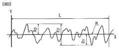
・表面粗さRaの定義
図1に示すように、粗さ曲線からその平均線の方向に基準長さLだけを抜き取り、この抜き取り部分の平均線の方向にX軸を、縦倍率の方向にY軸をとり、粗さ曲線をy=f(x)で表したときに、下記の数1によって求められる値をマイクロメートル(μm)で表したものをいう。尚、図1中、mは基準線である。Typical examples are LiFePO4 , LiCoPO4, and the like, for example, Li0.90 Ti0.05 Nb0.05 Fe0.30 Co0.30 Mn0.30 PO4, and the like. In particular, LiFePO4 is easy to obtain an iron compound as a raw material, but when using other transition metals such as Co, Ni, Mn, etc., it is a particle having the same crystal structure. Can be expected.
Further, the surface roughness Ra in the present application is defined in Japanese Industrial Standard (JIS B 0601-1994) (see below), and can be measured by, for example, a surface roughness meter.
・ Definition of surface roughness Ra As shown in FIG. 1, only the reference length L is extracted from the roughness curve in the direction of the average line, the X axis is in the direction of the average line of the extracted portion, and the direction of the vertical magnification is When the Y-axis is taken and the roughness curve is expressed by y = f (x), the value obtained by the following formula 1 is expressed in micrometers (μm). In FIG. 1, m is a reference line.

尚、正極活物質はオリビン型リン酸リチウム単独のものに限定するものではなく、オリビン型リン酸リチウムと他の正極材料との混合物でも構わない。 The positive electrode active material is not limited to olivine type lithium phosphate alone, and may be a mixture of olivine type lithium phosphate and other positive electrode materials.
請求項2記載の発明は請求項1記載の発明において、前記オリビン型リン酸リチウムとしてリン酸鉄リチウムを用いることを特徴とする。
上記構成の如く、オリビン型リン酸リチウムとしてリン酸鉄リチウムを用いれば、鉄は産出量が多く、安価であるということにより、電池の生産コストを大幅に低減させることができるという利点を有する。The invention according to
If lithium iron phosphate is used as the olivine-type lithium phosphate as described above, iron is produced in a large amount and is inexpensive, so that it has the advantage that the production cost of the battery can be greatly reduced.
請求項3記載の発明は請求項1記載の発明において、前記正極集電体にアルミニウム箔を用い、且つ、前記平均表面粗さRaが0.20μm未満であることを特徴とする。
また、請求項4記載の発明は請求項2記載の発明において、前記正極集電体にアルミニウム箔を用い、且つ、前記平均表面粗さRaが0.20μm未満であることを特徴とする。
請求項1記載の如く、正極の体積エネルギー密度の低下を防止するには、正極集電体の厚みを小さくする必要がある。一方、正極集電体の厚みを小さくし、且つ、平均表面粗さRa(μm)を大きくすると、正極集電体の強度が低下するという問題が生じる。According to a third aspect of the present invention, in the first aspect of the invention, an aluminum foil is used for the positive electrode current collector, and the average surface roughness Ra is less than 0.20 μm.
According to a fourth aspect of the invention, in the second aspect of the invention, an aluminum foil is used for the positive electrode current collector, and the average surface roughness Ra is less than 0.20 μm.
As described in claim 1, in order to prevent a decrease in the volume energy density of the positive electrode, it is necessary to reduce the thickness of the positive electrode current collector. On the other hand, when the thickness of the positive electrode current collector is reduced and the average surface roughness Ra (μm) is increased, there arises a problem that the strength of the positive electrode current collector is lowered.
ここで、正極集電体にアルミニウム箔を用いた場合には、引張り強度は160N/mm2以上、好ましくは170N/mm2以上であることが望ましい。そして、アルミニウム箔の厚さが20μm未満の正極集電体を用いて上記引張り強度を得るためには、正極集電体の平均表面粗さRaを0.20μm未満になるように規制するのが望ましいということが実験により認められた。Here, in the case of using the aluminum foil to the cathode current collector, the tensile strength is 160 N / mm2 or more, it is desirable that preferably 170N / mm2 or more. And in order to obtain the said tensile strength using the positive electrode electrical power collector whose thickness of aluminum foil is less than 20 micrometers, it regulates that average surface roughness Ra of a positive electrode electrical power collector will be less than 0.20 micrometer. Experiments have shown that this is desirable.
即ち、正極集電体にアルミニウム箔を用いた場合には、正極集電体の平均表面粗さRaは正極集電体の厚さの1/100以下であることが望ましい。但し、このことは、正極集電体をブラスト法による研磨を用いて作製した場合であり、これ以外の方法、例えば、エッチング法、めっき法等を用いて処理する場合には、正極集電体の平均表面粗さRaをもう少し大きくなるよう(例えば、正極集電体の厚さの約1/50以下)に規定しても良い。このように規定するのは、ブラスト法による研磨を用いる場合には、正極集電体に対する衝撃が大きいので、正極集電体の平均表面粗さRaを大きくすると、正極集電体の強度が低下する一方、エッチング法、めっき法等を用いて処理する場合には、正極集電体に対する衝撃が小さいので、正極集電体の平均表面粗さRaをある程度大きくしても、正極集電体の強度の低下を防止することができるという理由によるものである。 That is, when an aluminum foil is used for the positive electrode current collector, the average surface roughness Ra of the positive electrode current collector is desirably 1/100 or less of the thickness of the positive electrode current collector. However, this is a case where the positive electrode current collector is produced by polishing by a blast method, and in the case of processing using other methods such as an etching method or a plating method, the positive electrode current collector is used. The average surface roughness Ra may be specified to be a little larger (for example, about 1/50 or less of the thickness of the positive electrode current collector). This is because when the polishing by the blast method is used, the impact on the positive electrode current collector is large. Therefore, if the average surface roughness Ra of the positive electrode current collector is increased, the strength of the positive electrode current collector is decreased. On the other hand, when processing using an etching method, a plating method, etc., the impact on the positive electrode current collector is small, so even if the average surface roughness Ra of the positive electrode current collector is increased to some extent, This is because the strength can be prevented from decreasing.
請求項5記載の発明は請求項3記載の発明において、前記粗面化処理はブラスト法による研磨により行なわれることを特徴とする。
また、請求項6記載の発明は請求項4記載の発明において、前記粗面化処理はブラスト法による研磨により行なわれることを特徴とする。
このように規制するのは、以下に示す理由による。即ち、正極集電体を粗面化処理する場合に、正極集電体の強度の低下を防止するという観点からは、上述の如くエッチング法、めっき法等を用いるのが望ましいが、これらの方法では工程が煩雑で、製造コストが高くなる。これに対して、ブラスト法による研磨を用いる場合には、工程が煩雑ではなく、製造コストを低減できるからである。According to a fifth aspect of the invention, in the third aspect of the invention, the roughening treatment is performed by polishing by a blast method.
The invention according to
The reason for this restriction is as follows. That is, when roughening the positive electrode current collector, from the viewpoint of preventing the strength of the positive electrode current collector from being lowered, it is preferable to use the etching method, the plating method, etc. as described above. Then, a process is complicated and a manufacturing cost becomes high. On the other hand, when polishing by the blast method is used, the process is not complicated and the manufacturing cost can be reduced.
請求項7記載の発明は請求項2記載の発明において、前記リン酸鉄リチウムは平均粒径が10μm以下であることを特徴とする。 The invention according to claim 7 is the invention according to
このように正極活物質の平均粒子径を規制することにより、正極活物質の粒子内での充放電に伴うリチウムの拡散距離を制御することが可能となり、リチウムの挿入脱離に伴う抵抗を低減して、充放電特性を向上させる効果がある。即ち、粗度を制御することにより活物質粒子と正極集電体の接触面積を十分に確保しうる点で、粒子径を制御したリン酸鉄リチウム(LiFePO4)を用いればより効果的である。尚、正極活物質の粒径をレーザー回折式粒度分布測定装置で測定したメディアン径(Rmedian)とモード径(Rmode)とが共に10μm以下であることが望ましく、好ましくは5μm以下の粒子であることが望まれる。In this way, by regulating the average particle diameter of the positive electrode active material, it becomes possible to control the diffusion distance of lithium accompanying charging / discharging in the particles of the positive electrode active material, and reducing the resistance accompanying lithium insertion / extraction. Thus, there is an effect of improving the charge / discharge characteristics. That is, it is more effective to use lithium iron phosphate (LiFePO4 ) with a controlled particle diameter in that the contact area between the active material particles and the positive electrode current collector can be sufficiently secured by controlling the roughness. . The median diameter (Rmedian ) and mode diameter (Rmode ) of the positive electrode active material measured by a laser diffraction particle size distribution measuring device are both preferably 10 μm or less, preferably 5 μm or less. It is desirable to be.
請求項8記載の発明は請求項1記載の発明において、上記正極活物質含有層には導電剤が含まれており、且つ、この導電剤のBET比表面積が15m2/g以上に規制されると共に、上記正極活物質含有層における充填密度が1.7g/cm3以上に規制されることを特徴とする。
また、請求項9記載の発明は請求項2記載の発明において、上記正極活物質含有層には導電剤が含まれており、且つ、この導電剤のBET比表面積が15m2/g以上に規制されると共に、上記正極活物質含有層における充填密度が1.7g/cm3以上に規制されることを特徴とする。
また、請求項10記載の発明は請求項4記載の発明において、上記正極活物質含有層には導電剤が含まれており、且つ、この導電剤のBET比表面積が15m2/g以上に規制されると共に、上記正極活物質含有層における充填密度が1.7g/cm3以上に規制されることを特徴とする。The invention described in claim 8 is the invention described in claim 1, wherein the positive electrode active material-containing layer contains a conductive agent, and the BET specific surface area of the conductive agent is regulated to 15 m2 / g or more. In addition, the packing density in the positive electrode active material-containing layer is regulated to 1.7 g / cm3 or more.
The invention described in claim 9 is the invention described in
The invention described in
上記構成の如く、導電剤のBET比表面積を15m2/g以上、正極活物質含有層における充填密度を1.7g/cm3以上に、それぞれ規制すれば、正極活物質にリン酸鉄リチウム等のオリビン型リン酸リチウムが含まれていても、正極におけるエネルギー密度を低下させることなく、電子導電性を格段に向上させることができるので、高容量化を図ることができると共にハイレート放電時の放電性能を飛躍的に向上させることができる。これは、以下に示す理由によるものと考えられる。If the BET specific surface area of the conductive agent is regulated to 15 m2 / g or more and the packing density in the positive electrode active material-containing layer to 1.7 g / cm3 or more as described above, the positive electrode active material may be lithium iron phosphate or the like. Even if olivine type lithium phosphate is contained, the electronic conductivity can be remarkably improved without lowering the energy density in the positive electrode, so that the capacity can be increased and the discharge at the high rate discharge can be achieved. Performance can be improved dramatically. This is considered to be due to the following reasons.
即ち、本発明者が鋭意実験を行ったところ、導電剤のBET比表面積が15m2/g未満の場合には、正極活物質と導電剤との接触面積が小さくなり、また、正極活物質含有層における充填密度が1.7g/cm3未満の場合には、正極におけるエネルギー密度が低下し、しかも正極活物質と導電剤、及び正極活物質と正極集電体との密着性が低くなることが認められた。これらのことから、導電剤のBET比表面積や正極活物質含有層における充填密度が小さいと、正極におけるエネルギー密度が低下すると共に、正極内での電子導電性が不十分となって、高容量化を図ることができず、且つ、ハイレート放電時の放電性能が低下することがわかった。That is, when the present inventor conducted earnest experiments, when the BET specific surface area of the conductive agent is less than 15 m2 / g, the contact area between the positive electrode active material and the conductive agent becomes small, and the positive electrode active material contained When the packing density in the layer is less than 1.7 g / cm3 , the energy density in the positive electrode is decreased, and the adhesion between the positive electrode active material and the conductive agent and between the positive electrode active material and the positive electrode current collector is reduced. Was recognized. For these reasons, if the BET specific surface area of the conductive agent and the packing density in the positive electrode active material-containing layer are small, the energy density in the positive electrode is lowered and the electron conductivity in the positive electrode is insufficient, resulting in high capacity. It was found that the discharge performance at the time of high-rate discharge deteriorates.
これに対して、上記構成の如く、導電剤のBET比表面積を15m2/g以上に規制すると、導電剤の粒径が小さくなり、正極活物質の表面上に十分な量の導電剤を分散させることができるので、正極活物質と導電剤との接触面積が大きくなり、且つ、正極活物質含有層における充填密度を1.7g/cm3以上に規制すると、正極におけるエネルギー密度を低下させることなく、正極活物質と導電剤、及び正極活物質と正極集電体との密着性が高まることが認められた。これらのことから、導電剤のBET比表面積や正極活物質含有層における充填密度を上記の如く規制すると、正極におけるエネルギー密度を低下させることなく、正極内に良好な導電パスが形成されて、正極内の電子導電性が飛躍的に高まるので、電池の高容量化を図ることができると共にハイレートでの放電性能を飛躍的に向上させることができる。
尚、導電性粉末としては、導電性カーボン粉末が好ましく用いられるが、導電性のある金属酸化物等も用いることができる。また、導電性粉末の添加量が多すぎると正極活物質の混合割合が相対的に減少して、正極の充放電容量が小さくなるため、導電性粉末の添加量は正極合剤全体の質量に対して10質量%以下であるのが望ましい。On the other hand, when the BET specific surface area of the conductive agent is regulated to 15 m2 / g or more as in the above configuration, the particle size of the conductive agent is reduced, and a sufficient amount of the conductive agent is dispersed on the surface of the positive electrode active material. Therefore, when the contact area between the positive electrode active material and the conductive agent is increased and the packing density in the positive electrode active material-containing layer is regulated to 1.7 g / cm3 or more, the energy density in the positive electrode is reduced. It was confirmed that the adhesion between the positive electrode active material and the conductive agent and the positive electrode active material and the positive electrode current collector was increased. Therefore, when the BET specific surface area of the conductive agent and the packing density in the positive electrode active material-containing layer are regulated as described above, a good conductive path is formed in the positive electrode without reducing the energy density in the positive electrode. Since the electronic conductivity of the battery is greatly increased, the capacity of the battery can be increased and the discharge performance at a high rate can be dramatically improved.
In addition, as the conductive powder, conductive carbon powder is preferably used, but conductive metal oxides can also be used. In addition, if the amount of conductive powder added is too large, the mixing ratio of the positive electrode active material is relatively decreased, and the charge / discharge capacity of the positive electrode is reduced. Therefore, the amount of conductive powder added is the mass of the entire positive electrode mixture. On the other hand, it is desirable that it is 10 mass% or less.
請求項11記載の発明は請求項8記載の発明において、上記正極活物質含有層における充填密度が3.15g/cm3以下に規制されることを特徴とする。The invention described in claim 11 is characterized in that, in the invention described in claim 8, the packing density in the positive electrode active material-containing layer is regulated to 3.15 g / cm3 or less.
請求項12記載の発明は請求項9記載の発明において、上記正極活物質含有層における充填密度が3.15g/cm3以下に規制されることを特徴とする。
このように規制するのは、正極活物質含有層における充填密度が3.15g/cm3を超えると、正極内の空間が狭くなりすぎて、電極内へ含浸される電解液の量が少なくなり、電池の放電容量が低下することがあるという理由による。
上述のことから、正極活物質含有層における充填密度は1.7g/cm3以上3.15g/cm3以下に規制するのが望ましいが、その範囲の中でも、1.7g/cm3以上2.7g/cm3以下、特に2.0g/cm3以上2.3g/cm3以下に規制するのが望ましい。The invention described in claim 12 is characterized in that, in the invention described in claim 9, a packing density in the positive electrode active material-containing layer is regulated to 3.15 g / cm3 or less.
The reason for this restriction is that when the packing density in the positive electrode active material-containing layer exceeds 3.15 g / cm3 , the space in the positive electrode becomes too narrow, and the amount of the electrolyte solution impregnated in the electrode decreases. This is because the discharge capacity of the battery may decrease.
From the above, the filling density of the positive electrode active material-containing layer is desirably restricted to 1.7 g / cm3 or more 3.15 g / cm3 or less, even in this range, 1.7 g / cm3 or more 2. It is desirable to regulate to 7 g / cm3 or less, particularly 2.0 g / cm3 or more and 2.3 g / cm3 or less.
請求項13記載の発明は請求項1記載の発明において、前記正極活物質粒子の表面上には炭素がコーティング又は付着されていることを特徴とする。
リン酸鉄リチウム等のオリビン型リン酸リチウムは電子導電性が低いことが課題であり、具体的には、層状岩塩構造を有するコバルト酸リチウムの導電性が約10−3S/cm以上であるのに対して、オリビン型リン酸リチウムの一種であるリン酸鉄リチウム(LiFePO4)の導電性は約10−10S/cmである。そこで、上記構成の如く、正極活物質粒子の表面上には炭素がコーティング又は付着されていれば、正極内における導電性をより向上させるという効果が期待できる。A thirteenth aspect of the invention is characterized in that, in the first aspect of the invention, carbon is coated or adhered on the surface of the positive electrode active material particles.
The problem with olivine-type lithium phosphates such as lithium iron phosphate is that the electronic conductivity is low. Specifically, the conductivity of lithium cobaltate having a layered rock salt structure is about 10−3 S / cm or more. On the other hand, the conductivity of lithium iron phosphate (LiFePO4 ), which is a kind of olivine type lithium phosphate, is about 10−10 S / cm. Therefore, as described above, if carbon is coated or adhered on the surface of the positive electrode active material particles, an effect of further improving the conductivity in the positive electrode can be expected.
請求項14記載の発明は請求項1記載の発明において、前記正極活物質におけるリチウムサイトの一部が遷移金属で置換されている、請求項1記載の非水電解質電池。
上記構成の如く、正極活物質におけるリチウムサイトの一部が遷移金属で置換されていても、正極内における導電性を向上させるという効果が期待できる。The invention according to claim 14 is the nonaqueous electrolyte battery according to claim 1, wherein a part of the lithium site in the positive electrode active material is replaced with a transition metal.
As in the above configuration, even when a part of the lithium site in the positive electrode active material is replaced with a transition metal, an effect of improving the conductivity in the positive electrode can be expected.
本発明によれば、正極におけるエネルギー密度を低下させることなく、正極内に良好な導電パスが形成されて、正極内の電子導電性が飛躍的に高まるので、電池の高容量化を図ることができると共にハイレートでの放電性能を飛躍的に向上させることができるという優れた効果を奏する。 According to the present invention, a good conductive path is formed in the positive electrode without reducing the energy density in the positive electrode, and the electronic conductivity in the positive electrode is dramatically increased, so that the capacity of the battery can be increased. In addition, it has an excellent effect that the discharge performance at a high rate can be dramatically improved.
[図1]表面粗さRaを説明するための説明図。
[図2]最大高さRmaxを説明するための説明図。
[図3]本発明の正極を用いた試験セルを模式的に示す図。FIG. 1 is an explanatory diagram for explaining a surface roughness Ra.
FIG. 2 is an explanatory diagram for explaining a maximum height Rmax .
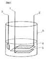
FIG. 3 is a diagram schematically showing a test cell using the positive electrode of the present invention.
1:正極
2:負極
4:非水電解質1: Positive electrode 2: Negative electrode 4: Non-aqueous electrolyte
ついで、本発明の最良の形態を以下に説明するが、本発明はこの形態に何ら限定されるものでなく、本発明の目的を変更しない範囲で適宜変更して実施することが可能である。 Next, the best mode of the present invention will be described below. However, the present invention is not limited to this mode, and can be implemented with appropriate modifications without departing from the object of the present invention.
[正極の作製]
先ず、正極活物質である平均粒径(メディアン径(Rmedian)とモード径(Rmode)の両方)が3μmのリン酸鉄リチウム(LiFePO4)が正極活物質含有層全体の85質量%と、導電剤であるアセチレンブラック(電気化学工業製 デンカブラック)が正極活物質含有層全体の10質量%となるように計量した後、両者を混合した。次に、この混合物に、結着剤であるポリアクリロニトリル(PAN)を正極活物質含有層全体の5質量%となるように加え、さらに溶媒であるN−メチルピロリドン(NMP)溶液を適量加えて混合することによりスラリーを作製した。[Production of positive electrode]
First, lithium iron phosphate (LiFePO4 ) having an average particle diameter (both median diameter (Rmedian ) and mode diameter (Rmode )) of 3 μm as the positive electrode active material is 85% by mass of the entire positive electrode active material-containing layer. Then, acetylene black (Denka Black, manufactured by Denki Kagaku Kogyo Co., Ltd.), which is a conductive agent, was weighed so as to be 10% by mass of the entire positive electrode active material-containing layer, and then mixed. Next, polyacrylonitrile (PAN) as a binder is added to this mixture so that it becomes 5% by mass of the whole positive electrode active material-containing layer, and an appropriate amount of N-methylpyrrolidone (NMP) solution as a solvent is added. A slurry was prepared by mixing.
一方、表面粗さRaが0.18μm(Ra=0.18μm)で、後述の定義により規定される最大高さRmaxが2.2μm(Rmax=2.2μm)で、厚みが19.4μmの粗面化ブラスト処理が施されたアルミ箔からなる正極集電体を用意した。次に、作製したスラリーをドクターブレード法により正極集電体の両面に塗布した。この後、ホットプレートを用いて80℃で乾燥させて、NMPを揮散させた。乾燥後、2cm×2cmのサイズに切り取り、ローラーを用いて所定の厚み(この場合は正極合剤層の片面の厚みは60μm)で、所定の活物質充填密度(この場合は2.2g/ml)となるように圧延し、更にこれを100℃で真空乾燥させることにより正極1を作製した。
・最大高さRyの定義
図2に示すように、粗さ曲線からその平均線の方向に基準長さLだけを抜き取り、この抜き取り部分の山頂線と谷底線との間隔(RP+RV)を粗さ曲線の縦倍率の方向に測定し、この値をマイクロメートル(μm)で表したものをいう。尚、図2中、mは基準線である。On the other hand, the surface roughness Ra is 0.18 μm (Ra = 0.18 μm), the maximum height Rmax specified by the definition described later is 2.2 μm (Rmax = 2.2 μm), and the thickness is 19.4 μm. A positive electrode current collector made of an aluminum foil subjected to the roughening blasting was prepared. Next, the prepared slurry was applied to both surfaces of the positive electrode current collector by a doctor blade method. Then, it dried at 80 degreeC using the hotplate, and NMP was volatilized. After drying, it is cut into a size of 2 cm × 2 cm, and is used with a roller to obtain a predetermined thickness (in this case, the thickness of one side of the positive electrode mixture layer is 60 μm) and a predetermined active material filling density (in this case, 2.2 g / ml) ) And then vacuum-dried at 100 ° C. to produce the positive electrode 1.
・ Definition of maximum height Ry As shown in FIG. 2, only the reference length L is extracted from the roughness curve in the direction of the average line, and the distance between the peak line and the valley line of the extracted part (RP +RV ) Is measured in the direction of the vertical magnification of the roughness curve, and this value is expressed in micrometers (μm). In FIG. 2, m is a reference line.
[負極の作製]
リチウム金属板を3cm×2.5cmのサイズに切り取ることにより、負極2を作製した。[Production of negative electrode]
The
[非水電解質の調製]
エチレンカーボネートとジエチルカーボネートとを1:1の体積比で混合した電解質に、リチウム塩としてのLiPF6を1モル/リットルとなるよう溶解させることにより非水電解質4を調製した。[Preparation of non-aqueous electrolyte]
A non-aqueous electrolyte 4 was prepared by dissolving LiPF6 as a lithium salt in an electrolyte in which ethylene carbonate and diethyl carbonate were mixed at a volume ratio of 1: 1 so as to be 1 mol / liter.
[試験セルの作製]
図3に示すように、不活性雰囲気下において、作用極としての上記正極1と、対極としての負極2とを、ポリエチレン製のセパレータ(旭化成株式会社製のハイポア)5を介して試験セル容器6内に配置し、試験セル容器6内に上記非水電解質4を注液することにより試験セルを作製した。尚、図3中、3はリチウム金属から成る参照極である。[Production of test cell]
As shown in FIG. 3, in an inert atmosphere, the positive electrode 1 as a working electrode and the
〔第1実施例〕
[実施例]
実施例としては、上記発明を実施するための最良の形態と同様にして、正極及び試験セルを作製した。
このようにして作製した正極及び試験セルを、以下、それぞれ本発明正極a及び本発明セルAと称する。
(比較例1)
粗面化ブラスト処理が施されていない表面粗さRaが0.026μm(Ra=0.026μm)で、最大高さRmaxが0.59μm(Rmax=0.59μm)で、厚みが15μmのアルミニウム箔からなる正極集電体を用いたこと以外は、実施例1と同様にして正極及び試験セルを作製した。
このようにして作製した正極及び試験セルを、以下、それぞれ比較正極x1及び比較セルX1と称する。[First embodiment]
[Example]
As examples, positive electrodes and test cells were produced in the same manner as in the best mode for carrying out the invention.
The positive electrode and the test cell thus produced are hereinafter referred to as the present invention positive electrode a and the present invention cell A, respectively.
(Comparative Example 1)
The surface roughness Ra not subjected to the roughening blast treatment is 0.026 μm (Ra = 0.026 μm), the maximum height Rmax is 0.59 μm (Rmax = 0.59 μm), and the thickness is 15 μm. A positive electrode and a test cell were produced in the same manner as in Example 1 except that a positive electrode current collector made of aluminum foil was used.
The positive electrode and the test cell thus produced are hereinafter referred to as a comparative positive electrode x1 and a comparative cell X1, respectively.
(比較例2)
表面粗さRaが0.28μm(Ra=0.28μm)で、最大高さRmaxが4.4μm(Rmax=4.4μm)で、厚みが30μmの粗面化ブラスト処理が施されたアルミニウム箔からなる正極集電体を用いたこと以外は、実施例1と同様にして正極及び試験セルを作製した。
このようにして作製した正極及び試験セルを、以下、それぞれ比較正極x2及び比較セルX2と称する。(Comparative Example 2)
Aluminum having a surface roughness Ra of 0.28 μm (Ra = 0.28 μm), a maximum height Rmax of 4.4 μm (Rmax = 4.4 μm), and a roughened blast treatment having a thickness of 30 μm A positive electrode and a test cell were produced in the same manner as in Example 1 except that a positive electrode current collector made of foil was used.
The positive electrode and the test cell thus produced are hereinafter referred to as a comparative positive electrode x2 and a comparative cell X2, respectively.
(実験1)
上記本発明セルA及び比較セルX1,2を用いて、放電電流が0.1It、0.2It、0.5It、1.0It、及び2.0Itの場合における、活物質1g当たりの放電容量(mAh/g)を調べたので、それらの結果を表1に示す。尚、充放電条件は以下の通りである。
[放電電流が0.1Itの場合の充放電条件]
・充電条件
0.1Itの充電電流で電池電圧が4.5Vになるまで充電。
・放電条件
0.1Itの放電電流で電池電圧が2.0Vになるまで放電。
上記条件で充放電を行って、1サイクル時の放電時間から活物質1g当たりの0.1It放電時の放電容量(mAh/g)を求めた。
[放電電流が0.2Itの場合の充放電条件]
上記放電電流が0.1Itの場合の充放電が終了した後、下記の条件で充放電を行った。
・充電条件
0.2Itの充電電流で電池電圧が4.5Vになるまで充電。
・放電条件
0.2Itの放電電流で電池電圧が2.0Vになるまで放電。
上記条件で充放電を2,3,4,5,6サイクルと繰り返した後、6サイクル時の放電時間から活物質1g当たりの0.2It放電時の放電容量(mAh/g)を求めた。(Experiment 1)
Using the present invention cell A and comparative cells X1 and 2, the discharge capacity per gram of active material (when the discharge current is 0.1 It, 0.2 It, 0.5 It, 1.0 It, and 2.0 It ( mAh / g) was examined and the results are shown in Table 1. The charging / discharging conditions are as follows.
[Charging / discharging conditions when the discharge current is 0.1 It]
-Charging conditions Charging until the battery voltage reaches 4.5 V with a charging current of 0.1 It.
-Discharge condition Discharge until the battery voltage reaches 2.0 V with a discharge current of 0.1 It.
Charging / discharging was performed under the above conditions, and the discharge capacity (mAh / g) at the time of 0.1 It discharge per 1 g of the active material was determined from the discharge time at one cycle.
[Charging / discharging conditions when the discharge current is 0.2 It]
After the charge / discharge in the case where the discharge current was 0.1 It was completed, charge / discharge was performed under the following conditions.
-Charging conditions Charging until the battery voltage reaches 4.5 V with a charging current of 0.2 It.
-Discharge conditions Discharge until the battery voltage reaches 2.0 V with a discharge current of 0.2 It.
After repeating charging, discharging, 2, 3, 4, 5, and 6 cycles under the above conditions, the discharge capacity (mAh / g) at the time of 0.2 It discharge per gram of active material was determined from the discharge time at the 6th cycle.
[放電電流が0.5Itの場合の充放電条件]
上記放電電流が0.2Itの場合の充放電が終了した後、下記の条件で充放電を行った。
・充電条件
0.2Itの充電電流で電池電圧が4.5Vになるまで充電。
・放電条件
0.5Itの放電電流で電池電圧が2.0Vになるまで放電。
7サイクル時の放電時間から活物質1g当たりの0.5It放電時の放電容量(mAh/g)を求めた。[Charging / discharging conditions when the discharge current is 0.5 It]
After the charge / discharge in the case where the discharge current was 0.2 It was charged / discharged under the following conditions.
-Charging conditions Charging until the battery voltage reaches 4.5 V with a charging current of 0.2 It.
-Discharge conditions Discharge until the battery voltage reaches 2.0 V with a discharge current of 0.5 It.
From the discharge time at 7 cycles, the discharge capacity (mAh / g) at 0.5 It discharge per 1 g of active material was determined.
[放電電流が1.0Itの場合の充放電条件]
上記放電電流が0.5Itの場合の充放電が終了した後、下記の条件で充放電を行った。
・充電条件
0.2Itの充電電流で電池電圧が4.5Vになるまで充電。
・放電条件
1.0Itの放電電流で電池電圧が2.0Vになるまで放電。
8サイクル時の放電時間から活物質1g当たりの1.0It放電時の放電容量(mAh/g)を求めた。[Charging / discharging conditions when the discharge current is 1.0 It]
After the charge / discharge in the case where the discharge current was 0.5 It was completed, charge / discharge was performed under the following conditions.
-Charging conditions Charging until the battery voltage reaches 4.5 V with a charging current of 0.2 It.
-Discharge conditions Discharge until the battery voltage reaches 2.0 V with a discharge current of 1.0 It.
The discharge capacity (mAh / g) at the time of 1.0 It discharge per 1 g of active material was determined from the discharge time at 8 cycles.
[放電電流が2.0Itの場合の充放電条件]
上記放電電流が1.0Itの場合の充放電が終了した後、下記の条件で充放電を行った。
・充電条件
0.2Itの充電電流で電池電圧が4.5Vになるまで充電。
・放電条件
2.0Itの放電電流で電池電圧が2.0Vになるまで放電。
9サイクル時の放電時間から活物質1g当たりの2.0It放電時の放電容量(mAh/g)を求めた。
尚、2.0It放電時の平均放電電圧を求めたところ、本発明セルAは2.8Vであり、比較セルX1は2.6Vであり、比較セルX2は2.8Vであった。
After the charge / discharge in the case where the discharge current was 1.0 It was completed, the charge / discharge was performed under the following conditions.
-Charging conditions Charging until the battery voltage reaches 4.5 V with a charging current of 0.2 It.
-Discharge condition Discharge until the battery voltage reaches 2.0 V with a discharge current of 2.0 It.
The discharge capacity (mAh / g) at the time of 2.0 It discharge per 1 g of active material was determined from the discharge time at 9 cycles.
In addition, when the average discharge voltage at the time of 2.0 It discharge was calculated | required, this invention cell A was 2.8V, the comparison cell X1 was 2.6V, and the comparison cell X2 was 2.8V.
上記表1の結果から明らかなように、粗面化ブラスト処理が施されていないアルミ箔からなる正極集電体を用いた比較正極x1を備えた比較セルX1においては、高レートの放電になるに伴って活物質1g当たりの放電容量が低下していることが分かる。これに対して、粗面化ブラスト処理が施されたアルミ箔からなる正極集電体を用いた本発明正極a,比較正極x2を備えた本発明セルA,比較セルX2においては、比較セルX1に比較して、高レートの放電になるに伴って活物質1g当たりの放電容量が向上していることが分かる。これは、粗面化処理を施したアルミニウム箔をからなる正極集電体を用いた本発明正極a,比較正極x2においては、正極集電体となるアルミニウム箔と正極合剤層との接触面積が増大して、接触抵抗が減少したために、活物質の利用率が向上して活物質1g当たりの放電容量が増大したためと考えられる。 As is clear from the results in Table 1 above, in the comparison cell X1 provided with the comparison positive electrode x1 using the positive electrode current collector made of an aluminum foil not subjected to the roughening blast treatment, the discharge becomes a high rate. It can be seen that the discharge capacity per gram of the active material is reduced. On the other hand, in the present invention cell A and the comparison cell X2 including the present invention positive electrode a and the comparison positive electrode x2 using the positive electrode current collector made of the aluminum foil subjected to the roughening blast treatment, the comparison cell X1 It can be seen that the discharge capacity per gram of the active material is improved as the discharge rate becomes higher. In the present invention positive electrode a using the positive electrode current collector made of a roughened aluminum foil and the comparative positive electrode x2, the contact area between the aluminum foil serving as the positive electrode current collector and the positive electrode mixture layer This is thought to be due to an increase in the active material utilization rate and an increase in the discharge capacity per gram of active material because the contact resistance decreased due to an increase in contact resistance.
(実験2)
上述の実験1の結果に基づいて、本発明正極a及び比較正極x1,x2の体積容量密度を下記(3)式に基づいて算出したので、その結果を表2に示す。
体積容量密度(mAh/ml)=正極活物質1g当たりの放電容量×(正極活物質の質量/正極合剤の質量)×(活物質の充填密度)×(正極合剤層の厚み/正極全体の厚み)・・・(3)(Experiment 2)
Since the volume capacity densities of the positive electrode a of the present invention and the comparative positive electrodes x1 and x2 were calculated based on the following equation (3) based on the results of the above-described Experiment 1, the results are shown in Table 2.
Volume capacity density (mAh / ml) = discharge capacity per gram of positive electrode active material × (mass of positive electrode active material / mass of positive electrode mixture) × (filling density of active material) × (thickness of positive electrode mixture layer / total positive electrode Thickness) ... (3)
ここで、例えば、本発明正極aの1.0It放電時においては、正極活物質1g当たりの放電容量は124.7(mAh/g)で、正極活物質の質量/正極合剤の質量=90/100で、活物質の充填密度は2.2g/mlで、正極合剤層の厚み/正極全体の厚み=(60+60)/(60+60+19.4)となる。これらの数値を上記(3)式に代入することにより、本発明正極aの1.0It放電時の体積容量密度は212.5mAh/mlであることが分かる。
上記表2の結果から明らかなように、粗面化ブラスト処理が施されたアルミ箔からなる正極集電体を用いた比較正極x2を備えた比較セルX2であっても、1.0It放電時には、粗面化ブラスト処理が施されていないアルミニウム箔からなる正極集電体を用いた比較正極x1を備えた比較セルX1に比較して体積エネルギー密度が低下していることが分かる。また、粗面化ブラスト処理が施されたアルミ箔からなる正極集電体を用いた本発明正極aを備えた本発明セルAにおいては、試験セルX1に比較して、1.0It放電時及び2.0It放電時の両方において体積エネルギー密度が向上していることが分かる。 As is apparent from the results in Table 2 above, even in the comparative cell X2 including the comparative positive electrode x2 using the positive electrode current collector made of the aluminum foil subjected to the roughening blast treatment, at the time of 1.0 It discharge It can be seen that the volume energy density is lower than that of the comparative cell X1 provided with the comparative positive electrode x1 using the positive electrode current collector made of the aluminum foil not subjected to the roughening blast treatment. Further, in the present invention cell A provided with the present invention positive electrode a using the positive electrode current collector made of the aluminum foil subjected to the roughening blasting treatment, compared with the test cell X1, at the time of 1.0 It discharge and It can be seen that the volume energy density is improved both at the time of 2.0 It discharge.
これは、比較正極x2においては、正極集電体となる粗面化アルミニウム箔の厚みが30μmと比較的厚いために、正極中に占める正極集電体の体積が増大して、正極の体積エネルギー密度が低下したと考えられる。このため、正極集電体となる粗面化アルミニウム箔の厚みは本発明正極aのように20μm未満であることが望ましい。この場合、厚みが20μm未満のアルミニウム箔の平均表面粗さRaを制御する必要があるが、ブラスト法を用いて平均表面粗さRaが0.20μm未満のアルミニウム箔を作製するのは技術的に困難となる場合も生じる。 This is because, in the comparative positive electrode x2, since the thickness of the roughened aluminum foil serving as the positive electrode current collector is relatively thick at 30 μm, the volume of the positive electrode current collector in the positive electrode increases and the volume energy of the positive electrode increases. The density is thought to have decreased. For this reason, the thickness of the roughened aluminum foil serving as the positive electrode current collector is desirably less than 20 μm as in the positive electrode a of the present invention. In this case, it is necessary to control the average surface roughness Ra of the aluminum foil having a thickness of less than 20 μm, but it is technically necessary to produce an aluminum foil having an average surface roughness Ra of less than 0.20 μm by using the blast method. Sometimes it becomes difficult.
このため、厚みが20μm未満のアルミニウム箔をブラスト法で粗面化する場合には、平均表面粗さRa(μm)は0.20μm未満になるように限定するのが望ましい。但し、平均表面粗さRa(μm)が小さ過ぎると、即ち、比較正極x1のように0.026μmの場合には、表1及び表2の結果から明らかなように、正極活物質と導電剤、導電剤と正極集電体、正極集電体と正極活物質のそれぞれの密着性を向上させることができない。これらの理由から、厚みが20μm未満のアルミニウム箔をブラスト法で粗面化する場合には、Ra(μm)は0.026μm<Ra<0.20μmの範囲になるように規定するのが望ましいということができる。 For this reason, when the aluminum foil having a thickness of less than 20 μm is roughened by blasting, it is desirable that the average surface roughness Ra (μm) is limited to be less than 0.20 μm. However, when the average surface roughness Ra (μm) is too small, that is, when the average surface roughness Ra (μm) is 0.026 μm as in the comparative positive electrode x1, as is clear from the results of Tables 1 and 2, the positive electrode active material and the conductive agent The adhesion between the conductive agent and the positive electrode current collector and between the positive electrode current collector and the positive electrode active material cannot be improved. For these reasons, when an aluminum foil having a thickness of less than 20 μm is roughened by blasting, it is desirable to define Ra (μm) to be in the range of 0.026 μm <Ra <0.20 μm. be able to.
このように、平均粗さRa(μm)が0.026μm<Ra<0.20μmの関係を有する正極集電体を用いることにより、正極活物質粒子と正極集電体との接触面積が大きくなるため、正極活物質粒子と正極集電体との密着性が大きく向上する。このため、正極合剤層の厚みが大きくなるように正極合剤層を正極集電体上に形成しても、正極合剤層の正極集電体からの剥離を防止できるようになる。この結果、正極集電体が正極合剤層を保持した状態を維持できるようになるので、従来から正極活物質として使用されているLiCoO2並みの容量分を同じ面積の正極集電体上に塗布することが可能となる。Thus, by using a positive electrode current collector having an average roughness Ra (μm) of 0.026 μm <Ra <0.20 μm, the contact area between the positive electrode active material particles and the positive electrode current collector is increased. Therefore, the adhesion between the positive electrode active material particles and the positive electrode current collector is greatly improved. For this reason, even if the positive electrode mixture layer is formed on the positive electrode current collector so that the thickness of the positive electrode mixture layer is increased, the positive electrode mixture layer can be prevented from peeling off from the positive electrode current collector. As a result, since the positive electrode current collector can maintain the state in which the positive electrode mixture layer is held, a capacity equivalent to that of LiCoO2 conventionally used as the positive electrode active material is placed on the positive electrode current collector of the same area. It becomes possible to apply.
〔第2実施例〕
[実施例1]
以下のようにして正極を作製する他は、前記第1実施例の実施例1と同様にして電池を作製した。
このようにして作製したセルを、以下、本発明セルB1と称する。
先ず、活物質であるリン酸鉄リチウム(LiFePO4)が正極活物質含有層全体の85質量%と、導電剤であるカーボンブラック(BET比表面積:70m2/g)が正極活物質含有層全体の10質量%となるように計量した後、両者を混合した。次に、この混合物に、結着剤であるポリアクリロニトリル(PAN)を正極活物質含有層全体の5質量%となるように加え、さらに溶媒であるN−メチルピロリドン(NMP)溶液を適量加えて混合することによりスラリーを調整した。次いで、このスラリーをドクタープレード法により、表面粗さRaが0.14μm(Ra=0.14μm)、最大高さRmaxが1.6μm(Rmax=1.6μm)、厚みが15.0μmの粗面化ブラスト処理が施されたアルミ箔上に塗布した。
この後、スラリー塗布電極をホットプレートを用いて80℃で乾燥させた後、この乾燥電極を厚さ0.1mmのSUS製の板で挟みつつ、P.C.コントローラー(日立株式会社製のPCF1075NH−AM)のローラー間を通過させるという工程を行って、上記乾燥電極の1回目の圧延を行った。この際の具体的な条件は、下記(1)の通りである。[Second Embodiment]
[Example 1]
A battery was produced in the same manner as in Example 1 of the first example except that the positive electrode was produced as follows.
The cell thus produced is hereinafter referred to as the present invention cell B1.
First, lithium iron phosphate (LiFePO4 ) as an active material is 85% by mass of the entire positive electrode active material-containing layer, and carbon black (BET specific surface area: 70 m2 / g) as a conductive agent is the entire positive electrode active material-containing layer. Were weighed so as to be 10% by mass, and then both were mixed. Next, polyacrylonitrile (PAN) as a binder is added to this mixture so that it becomes 5% by mass of the whole positive electrode active material-containing layer, and an appropriate amount of N-methylpyrrolidone (NMP) solution as a solvent is added. The slurry was prepared by mixing. Then, this slurry was subjected to a doctor blade method with a surface roughness Ra of 0.14 μm (Ra = 0.14 μm), a maximum height Rmax of 1.6 μm (Rmax = 1.6 μm), and a thickness of 15.0 μm. It apply | coated on the aluminum foil in which the roughening blast process was given.
Thereafter, the slurry-coated electrode was dried at 80 ° C. using a hot plate, and then the dry electrode was sandwiched between SUS plates having a thickness of 0.1 mm. C. The process of passing between the rollers of a controller (PCF1075NH-AM manufactured by Hitachi, Ltd.) was performed, and the first rolling of the dry electrode was performed. Specific conditions at this time are as follows (1).
(1)1回目の圧延条件
・ローラーのスリット幅:150μm
・ローラーの回転速度:200rpm
・ローラーの通過回数:4回
しかる後、圧延電極を2cm×2cmのサイズに切り取った後、厚さ0.1mmのSUS製の板でスラリー塗布物を挟みつつ、上記と同様のP.C.コントローラーでローラー間のスリット幅を変化させて通過させるという工程を2回行って、上記圧延電極を更に圧延した。この際の具体的な条件は、下記(2)(3)の通りである。(1) Rolling conditions for the first time / Slit width of roller: 150 μm
・ Roller rotation speed: 200rpm
-Number of times the roller passes: After that, after the rolled electrode is cut to a size of 2 cm x 2 cm, the slurry coating is sandwiched between SUS plates having a thickness of 0.1 mm, and the same P.D. C. The process of changing the slit width between the rollers with a controller was passed twice to further roll the rolling electrode. Specific conditions at this time are as follows (2) and (3).
(2)2回目の圧延条件
・ローラーのスリット幅:120μm
・ローラーの回転速度:200rpm
・ローラーの通過回数:4回
(3)3回目の圧延条件
・ローラー間のスリット幅:100μm
・ローラーの回転速度:200rpm
・ローラーの通過回数:4回
最後に、100℃で真空乾燥させて正極を作製した。(2) Second rolling conditions and roller slit width: 120 μm
・ Roller rotation speed: 200rpm
・ Number of roller passes: 4 times (3) Rolling conditions for the third time ・ Slit width between rollers: 100 μm
・ Roller rotation speed: 200rpm
-Number of passes of roller: 4 times Finally, a positive electrode was produced by vacuum drying at 100 ° C.
[実施例2]
導電剤であるカーボンブラックとして、BET比表面積が39m2/gのものを用いる他は、上記実施例1と同様にして試験セルを作製した。
このようにして作製したセルを、以下、本発明セルB2と称する。[Example 2]
A test cell was prepared in the same manner as in Example 1 except that carbon black as a conductive agent was used having a BET specific surface area of 39 m2 / g.
The cell thus produced is hereinafter referred to as the present invention cell B2.
[実施例3]
導電剤であるカーボンブラックとして、BET比表面積が15m2/gのものを用いる他は、上記実施例1と同様にして試験セルを作製した。
このようにして作製したセルを、以下、本発明セルB3と称する。[Example 3]
A test cell was prepared in the same manner as in Example 1 except that carbon black as the conductive agent was used having a BET specific surface area of 15 m2 / g.
The cell thus produced is hereinafter referred to as the present invention cell B3.
[実施例4]
導電剤であるカーボンブラックとして、BET比表面積が90m2/gのものを用いる他は、上記実施例1と同様にして試験セルを作製した。
このようにして作製したセルを、以下、本発明セルB4と称する。[Example 4]
A test cell was prepared in the same manner as in Example 1 except that carbon black as a conductive agent was used having a BET specific surface area of 90 m2 / g.
The cell thus produced is hereinafter referred to as the present invention cell B4.
[実施例5]
導電剤であるカーボンブラックとして、BET比表面積が300m2/gのものを用いる他は、上記実施例1と同様にして試験セルを作製した。
このようにして作製したセルを、以下、本発明セルB5と称する。[Example 5]
A test cell was prepared in the same manner as in Example 1 except that carbon black as a conductive agent was used having a BET specific surface area of 300 m2 / g.
The cell thus produced is hereinafter referred to as the present invention cell B5.
[実施例6]
活物質であるリン酸鉄リチウムが正極活物質含有層全体の90質量%と、上記実施例1で用いたBET比表面積が70m2/gのものが正極活物質含有層全体の5質量%となるよう規定した他は、上記実施例1と同様にして試験セルを作製した。
このようにして作製したセルを、以下、本発明セルB6と称する。[Example 6]
Lithium iron phosphate and 90% by weight of the total cathode active material-containing layer as an active material, BET specific surface area used in the above Example 1 is
The cell thus produced is hereinafter referred to as the present invention cell B6.
[実施例7]
導電剤であるカーボンブラックとして、上記実施例1で用いたBET比表面積が70m2/gのものと、上記実施例3で用いたBET比表面積が15m2/gのものとを、それぞれ正極活物質含有層全体の5質量%ずつの割合となるように混合したものを用いる他は、上記実施例1と同様にして試験セルを作製した。
このようにして作製したセルを、以下、本発明セルB7と称する。[Example 7]
As carbon black as a conductive agent, those having a BET specific surface area of 70 m2 / g used in Example 1 and those having a BET specific surface area of 15 m2 / g used in Example 3 were respectively used as positive electrode active materials. A test cell was prepared in the same manner as in Example 1 except that the material-containing layer was mixed so as to have a ratio of 5% by mass.
The cell thus produced is hereinafter referred to as the present invention cell B7.
(比較例1)
導電剤であるカーボンブラックとして、BET比表面積が12m2/gのものを用いる他は、上記実施例1と同様にして試験セルを作製した。
このようにして作製したセルを、以下、比較セルY1と称する。(Comparative Example 1)
A test cell was prepared in the same manner as in Example 1 except that carbon black as a conductive agent was used having a BET specific surface area of 12 m2 / g.
The cell thus produced is hereinafter referred to as a comparison cell Y1.
(比較例2)
発明を実施するための最良の形態に示した(1)1回目の圧延条件でのみ極板を圧延し、2回目、3回目の圧延を行わない他は、上記実施例1と同様にして試験セルを作製した。
このようにして作製したセルを、以下、比較セルY2と称する。(Comparative Example 2)
(1) Tested in the same manner as in Example 1 except that the electrode plate was rolled only under the first rolling conditions and the second and third rolling operations were not performed. A cell was produced.
The cell thus fabricated is hereinafter referred to as a comparison cell Y2.
(実験)
上記本発明セルB1〜B7及び比較セルY1、Y2の正極活物質含有層における充填密度を計測し、更にこの値から正極活物質のみの充填密度を算出すると共に、前記第1実施例の実験1に示す条件と同様の充放電条件で充放電を繰り返し行い、正極活物質1gあたりの放電容量を調べたので、その結果を表3に示す。(Experiment)
The packing density in the positive electrode active material-containing layers of the present invention cells B1 to B7 and the comparative cells Y1 and Y2 is measured, and from this value, the packing density of only the positive electrode active material is calculated, and the experiment 1 of the first embodiment is performed. Table 3 shows the results of charging / discharging repeatedly under the same charging / discharging conditions as those shown in FIG. 1 and examining the discharge capacity per gram of the positive electrode active material.
表3から明らかなように、BET比表面積15m2/g以上の導電剤を用い、且つ正極活物質含有層の充填密度を1.7g/cm3以上とした本発明セルB1〜B7では、ローレートでの放電時(放電電流0.1It〜0.5It)のみならず、ハイレートでの放電時(放電電流1It〜2It)でも大きな放電容量が得られることが認められた。これに対して、BET比表面積の小さな(BET比表面積:12m2/g)比較セルY1では、正極活物質含有層における充填密度が大きい(充填密度:2.2g/cm3)にもかかわらず、ローレートでの放電及びハイレートでの放電において非常に小さな放電容量しか得られなかった。また、正極活物質含有層における充填密度の小さな(充填密度:1.6g/cm3)比較セルY2では、BET比表面積が大きい(BET比表面積:70m2/g)ので、ローレートの放電の中でも微弱な放電時(放電電流0.1It〜0.2It)にはある程度の放電容量が得られるが、ローレートの放電の中でも若干大きな放電時(放電電流0.5It)には放電容量が極めて小さくなり、ハイレートの放電時(放電電流1It〜2It)には、放電できないことが認められた。As is apparent from Table 3, in the cells B1 to B7 of the present invention in which a conductive agent having a BET specific surface area of 15 m2 / g or more was used and the packing density of the positive electrode active material-containing layer was 1.7 g / cm3 or more, It was confirmed that a large discharge capacity can be obtained not only at the time of discharge (discharge current 0.1 It to 0.5 It) but also at the time of discharge at high rate (discharge current 1 It to 2 It). In contrast, in the comparative cell Y1 having a small BET specific surface area (BET specific surface area: 12 m2 / g), the packing density in the positive electrode active material-containing layer is large (packing density: 2.2 g / cm3 ). Only a very small discharge capacity was obtained in the discharge at the low rate and the discharge at the high rate. Further, in the comparison cell Y2 having a small packing density in the positive electrode active material-containing layer (packing density: 1.6 g / cm3 ), the BET specific surface area is large (BET specific surface area: 70 m2 / g). A certain amount of discharge capacity can be obtained during a weak discharge (discharge current 0.1 It to 0.2 It), but the discharge capacity becomes extremely small during a slightly large discharge (discharge current 0.5 It) among low-rate discharges. It was confirmed that during high-rate discharge (discharge currents 1 It to 2 It), discharge was not possible.
このような結果となったのは、以下に示す理由によるものと考えられる。即ち、BET比表面積の小さな導電剤を用いた比較セルY1では、正極活物質であるリン酸鉄リチムと導電剤との接触面積が小さくなり、また、正極活物質含有層における充填密度の小さな比較セルY2では、正極活物質と導電剤、及び正極活物質と正極集電体との密着性が低くなる。これらのことから、導電剤のBET比表面積や正極活物質含有層における充填密度が小さいと、正極内の電子導電性が不十分となる。これに対して、BET比表面積15m2/g以上の導電剤を用い、且つ正極活物質含有層における充填密度を1.7g/cm3以上とした本発明セルB1〜B7では、導電剤の粒径が小さくなって、正極活物質であるリン酸鉄リチウムの表面上に十分な量の導電剤を分散させることができるので、正極活物質と導電剤との接触面積が大きくなり、且つ、正極活物質含有層における充填密度が大きいので、正極活物質であるリン酸鉄リチウムと導電剤、及び正極活物質と正極集電体との密着性が高まる。これらのことから、本発明セルB1〜B7では、正極内に良好な導電パスが形成されて、正極内の電子導電性が飛躍的に高まるという理由によるものと考えられる。Such a result is considered to be due to the following reasons. That is, in the comparison cell Y1 using a conductive agent with a small BET specific surface area, the contact area between the positive electrode active material, iron phosphate lithium, and the conductive agent is small, and the comparison is also made with a small packing density in the positive electrode active material-containing layer. In the cell Y2, the adhesion between the positive electrode active material and the conductive agent, and the positive electrode active material and the positive electrode current collector is lowered. From these things, when the BET specific surface area of a electrically conductive agent and the packing density in a positive electrode active material content layer are small, the electronic conductivity in a positive electrode will become inadequate. In contrast, in the cells B1 to B7 of the present invention in which a conductive agent having a BET specific surface area of 15 m2 / g or more was used and the packing density in the positive electrode active material-containing layer was 1.7 g / cm3 or more, the conductive agent particles Since the diameter is reduced and a sufficient amount of the conductive agent can be dispersed on the surface of the lithium iron phosphate that is the positive electrode active material, the contact area between the positive electrode active material and the conductive agent is increased, and the positive electrode Since the packing density in the active material-containing layer is large, the adhesion between the lithium iron phosphate that is the positive electrode active material and the conductive agent, and the positive electrode active material and the positive electrode current collector is increased. From these facts, it is considered that in the present invention cells B1 to B7, a good conductive path is formed in the positive electrode, and the electronic conductivity in the positive electrode is dramatically increased.
〔第3実施例〕
[実施例1]
実施例1としては、上記第2実施例の実施例6に示す本発明セルB6を用いた。
[実施例2]
正極集電体として、粗面化していないもの[表面粗さRaが0.026μm(Ra=0.026μm)]を用いる他は、上記実施例1と同様にして試験セルを作製した。
このようにして作製したセルを、以下、本発明セルCと称する。[Third embodiment]
[Example 1]
As Example 1, this invention cell B6 shown in Example 6 of the said 2nd Example was used.
[Example 2]
A test cell was prepared in the same manner as in Example 1 except that a non-roughened material [surface roughness Ra was 0.026 μm (Ra = 0.026 μm)] was used as the positive electrode current collector.
The cell thus produced is hereinafter referred to as the present invention cell C.
(実験)
上記本発明セルB6、Cの正極活物質含有層における充填密度を計測し、更にこの値から正極活物質のみの充填密度を算出すると共に、前記第1実施例の実験と同様の充放電条件で充放電を繰り返し行い、正極活物質1gあたりの放電容量を調べたので、その結果を表4に示す。(Experiment)
The packing density in the positive electrode active material-containing layer of the cells B6 and C of the present invention is measured, and from this value, the packing density of only the positive electrode active material is calculated, and under the same charge / discharge conditions as in the experiment of the first embodiment. The charge / discharge was repeated, and the discharge capacity per gram of the positive electrode active material was examined. Table 4 shows the results.
上記表4から明らかなように、ローレートでの放電容量では両者間に差異は認められないが、ハイレートでの放電容量では、本発明セルB6は本発明セルCに比べて放電容量が大きくなっていることが認められる。 As is apparent from Table 4 above, no difference is observed between the discharge capacity at the low rate, but the discharge capacity at the high rate discharge cell of the present invention cell B6 is larger than that of the present invention cell C. It is recognized that
このような結果となったのは、以下に示す理由によるものと考えられる。即ち、正極集電体として粗面化したアルミニウム箔を用いた本発明セルB6では、正極集電体の表面に凹凸が存在しているため、正極集電体と導電剤、及び正極集電体と正極活物質との接触面積が大きくなって、これら両者間の密着性をより高めることができる。これに対して、正極集電体として粗面化していないアルミニウム箔を用いた本発明セルCでは、正極集電体の表面に凹凸が存在していないため、正極集電体と導電剤、及び正極集電体と正極活物質との接触面積が若干小さくなって、これら両者間の密着性が多少低くなるという理由によるものと考えられる。
(その他の事項)
(1)上記第1実施例〜第3実施例では、正極活物質にリン酸鉄リチウムのみを用いているが、本発明はこのような構成に限定するものではなく、正極活物質にリン酸鉄リチウム等のオリビン型リン酸リチウムが含まれていれば本発明の効果を発揮しうる。
(2)上記第1実施例〜第3実施例では、正極集電体の粗面化処理としてブラスト法を用いたがこれに限定するものではなく、サンドペーパーによる研磨法、物理的エッチングや化学的エッチングによるエッチング法、真空蒸着法、スパッタリング法、CVD法等の乾式めっき法、電解めっき法、無電解めっき法等の湿式めっき法であっても良い。具体的には、以下のようにして行う。
・エッチング法
例えば、正極集電体上にレジストを塗布した後、不要部分のレジストを除去し、このレジスト除去部分をエッチングすることにより、正極集電体表面に凹凸を形成する方法である。
・乾式めっき法
正極集電体を保持するホルダーをメッシュ状にする等、正極集電体の一部をマスキングすることにより、正極集電体の表面の一部にめっきを行なって、正極集電体表面に凹凸を形成する方法である。
・湿式めっき法表面
上記エッチング法と同様に、正極集電体上の一部にレジストを塗布するか、或いは正極集電体上にマスキングテープ等を貼着し後、正極集電体の表面の一部にめっきを行なって、正極集電体表面に凹凸を形成する方法である。
(3)上記第1実施例〜第3実施例では、正極集電体としてアルミニウムを用いたが、これに限定するものではない。但し、酸化電位が高く、正極充電時にも集電体が酸化溶解しないという利点を備えたアルミニウムを用いるのが好ましい。
(4)上記第2実施例及び第3実施例では、極板の圧延を3回行っているが、この回数に限定するものではなく、1回、2回でも良いし、4回以上であっても良いことは勿論である。Such a result is considered to be due to the following reasons. That is, in the present invention cell B6 using the roughened aluminum foil as the positive electrode current collector, since the surface of the positive electrode current collector is uneven, the positive electrode current collector, the conductive agent, and the positive electrode current collector The contact area between the positive electrode active material and the positive electrode active material is increased, and the adhesion between them can be further increased. On the other hand, in the present invention cell C using an unroughened aluminum foil as the positive electrode current collector, since there are no irregularities on the surface of the positive electrode current collector, the positive electrode current collector and the conductive agent, and This is probably because the contact area between the positive electrode current collector and the positive electrode active material is slightly reduced, and the adhesion between the two is somewhat reduced.
(Other matters)
(1) In the first to third embodiments, only lithium iron phosphate is used as the positive electrode active material. However, the present invention is not limited to such a configuration, and phosphoric acid is used as the positive electrode active material. If the olivine type lithium phosphate such as iron lithium is contained, the effects of the present invention can be exhibited.
(2) In the first to third embodiments, the blast method is used for the roughening treatment of the positive electrode current collector, but the present invention is not limited to this. It may be an etching method by mechanical etching, a vacuum plating method, a sputtering method, a dry plating method such as a CVD method, a wet plating method such as an electrolytic plating method or an electroless plating method. Specifically, this is performed as follows.
Etching Method For example, after applying a resist on the positive electrode current collector, unnecessary portions of the resist are removed, and this resist removed portion is etched to form irregularities on the surface of the positive electrode current collector.
・ Dry plating method By plating a part of the surface of the positive electrode current collector by masking a part of the positive electrode current collector, such as making the holder holding the positive electrode current collector into a mesh shape, the positive electrode current collector This is a method of forming irregularities on the body surface.
・ Wet plating surface As in the above etching method, a resist is applied to a part of the positive electrode current collector, or a masking tape or the like is applied on the positive electrode current collector, and then the surface of the positive electrode current collector is coated. In this method, a part is plated to form irregularities on the surface of the positive electrode current collector.
(3) In the first to third embodiments, aluminum is used as the positive electrode current collector, but the present invention is not limited to this. However, it is preferable to use aluminum having an advantage that the oxidation potential is high and the current collector is not oxidized and dissolved even when the positive electrode is charged.
(4) In the second embodiment and the third embodiment, the electrode plate is rolled three times. However, the number of times is not limited to this, and may be once, twice, or four times or more. Of course, it may be.
(5)非水電解質としては、エチレンカーボネート、ジエチルカーボネートに限定するものではなく、その他の環状炭酸エステル、鎖状炭酸エステル、エステル類、環状エーテル類、鎖状エーテル類、ニトリル類、アミド類等を用いることができる。
上記環状炭酸エステルとしては、上記エチレンカーボネートの他、プロピレンカーボネート、ブチレンカーボネート等が挙げられ、これらの水素基の一部または全部をフッ素化されているものも用いることが可能で、トリフルオロプロピレンカーボネートやフルオロエチルカーボネート等が挙げられる。(5) The non-aqueous electrolyte is not limited to ethylene carbonate and diethyl carbonate, but other cyclic carbonates, chain carbonates, esters, cyclic ethers, chain ethers, nitriles, amides, etc. Can be used.
Examples of the cyclic carbonate include propylene carbonate and butylene carbonate in addition to the above ethylene carbonate, and those in which some or all of these hydrogen groups are fluorinated can also be used. And fluoroethyl carbonate.
上記鎖状炭酸エステルとしては、上記ジエチルカーボネートの他、ジメチルカーボネート、エチルメチルカーボネート、メチルプロピルカーボネート、エチルプロピルカーボネート、メチルイソプロピルカーボネート等が挙げられ、これらの水素の一部または全部をフッ素化されているものも用いることが可能である。上記エステル類としては、酢酸メチル、酢酸エチル、酢酸プロピル、プロピオン酸メチル、プロピオン酸エチル、γ−ブチロラクトン等が挙げられる。 Examples of the chain carbonate include dimethyl carbonate, ethyl methyl carbonate, methyl propyl carbonate, ethyl propyl carbonate, methyl isopropyl carbonate, etc. in addition to the above diethyl carbonate, and some or all of these hydrogens are fluorinated. It is also possible to use what is. Examples of the esters include methyl acetate, ethyl acetate, propyl acetate, methyl propionate, ethyl propionate, and γ-butyrolactone.
上記環状エーテル類としては、1、3−ジオキソラン、4−メチル−1,3−ジオキソラン、テトラヒドロフラン、2−メチルテトラヒドロフラン、プロピレンオキシド、1,2−ブチレンオキシド、1,4−ジオキサン、1,3,5−トリオキサン、フラン、2−メチルフラン、1,8−シネオール、クラウンエーテル等が挙げられる。 Examples of the cyclic ethers include 1,3-dioxolane, 4-methyl-1,3-dioxolane, tetrahydrofuran, 2-methyltetrahydrofuran, propylene oxide, 1,2-butylene oxide, 1,4-dioxane, 1,3, 5-Trioxane, furan, 2-methylfuran, 1,8-cineol, crown ether and the like can be mentioned.
上記鎖状エーテル類としては、1,2−ジメトキシエタン、ジエチルエーテル、ジプロピルエーテル、ジイソプロピルエーテル、ジブチルエーテル、ジヘキシルエーテル、エチルビニルエーテル、ブチルビニルエーテル、メチルフェニルエーテル、エチルフェニルエーテル、ブチルフェニルエーテル、ペンチルフェニルエーテル、メトキシトルエン、ベンジルエチルエーテル、ジフェニルエーテル、ジベンジルエーテル、0−ジメトキシベンゼン、1,2−ジエトキシエタン、1,2−ジブトキシエタン、ジエチレングリコールジメチルエーテル、ジエチレングリコールジエチルエーテル、ジエチレングリコールジブチルエーテル、1,1−ジメトキシメタン、1,1−ジエトキシエタン、トリエチレングリコールジメチルエーテル、テトラエチレングリコールジメチル等が挙げられる。 Examples of the chain ethers include 1,2-dimethoxyethane, diethyl ether, dipropyl ether, diisopropyl ether, dibutyl ether, dihexyl ether, ethyl vinyl ether, butyl vinyl ether, methyl phenyl ether, ethyl phenyl ether, butyl phenyl ether, and pentyl. Phenyl ether, methoxytoluene, benzyl ethyl ether, diphenyl ether, dibenzyl ether, 0-dimethoxybenzene, 1,2-diethoxyethane, 1,2-dibutoxyethane, diethylene glycol dimethyl ether, diethylene glycol diethyl ether, diethylene glycol dibutyl ether, 1, 1-dimethoxymethane, 1,1-diethoxyethane, triethylene glycol dimethyl ether, tetra Chi glycol dimethyl and the like.
上記ニトリル類としてはアセトニトリル等が挙げられる。アミド類としてはジメチルホルムアミド等が挙げられる。特に、電圧安定性の点からは、エチレンカーボネート、プロピレンカーボネート等の環状炭酸エステル、ジメチルカーボネート、ジエチルカーボネート、ジプロピルカーボネート等の鎖状炭酸エステル類を使用することが好ましい。 Examples of the nitriles include acetonitrile. Examples of amides include dimethylformamide. In particular, from the viewpoint of voltage stability, it is preferable to use cyclic carbonates such as ethylene carbonate and propylene carbonate, and chain carbonates such as dimethyl carbonate, diethyl carbonate and dipropyl carbonate.
電解質としては、上記LiPF6に限定するものではなく、LiAsF6,LiBF4,LiCF3SO3,LiN(ClF2l+1SO2)(CmF2m+1SO2)(l,mは1以上の整数)、LiC(CpF2p+1SO2)(CqF2q+1SO2)(CrF2r+1SO2)(p,q,rは1以上の整数)等を用いることができる。また、下記の化1に示されるようなジフルオロ(オキサラト)ホウ酸リチウム等も用いることができる。これらの電解質は一種類で使用してもよく、また、二種類以上を組み合わせて使用してもよい。これらの電解質は、上述した非水溶媒に0.1〜1.5M、好ましくは、0.5〜1.5Mの濃度となるように溶解して使用するのが望ましい。
本発明は、例えば携帯電話、ノートパソコン、PDA等の移動情報端末の駆動電源のみならず、電気自動車やハイブリッド自動車の車載用電源等の大型電池に適用することもできる。 The present invention can be applied not only to a driving power source of a mobile information terminal such as a mobile phone, a notebook computer, and a PDA, but also to a large battery such as an in-vehicle power source of an electric vehicle or a hybrid vehicle.
Claims (14)
Translated fromJapanese前記正極集電体は厚みが20μm未満であるとともに、前記正極活物質含有層に接する面の平均表面粗さRaが0.026μmを超えていることを特徴とする非水電解質電池。In a nonaqueous electrolyte battery comprising a positive electrode active material-containing layer containing olivine-type lithium phosphate as a positive electrode active material and formed on a positive electrode current collector, a positive electrode, a negative electrode, and a nonaqueous electrolyte,
The positive electrode current collector has a thickness of less than 20 μm, and an average surface roughness Ra of a surface in contact with the positive electrode active material-containing layer exceeds 0.026 μm.
Applications Claiming Priority (5)
| Application Number | Priority Date | Filing Date | Title |
|---|---|---|---|
| JP2004058375 | 2004-03-03 | ||
| JP2004058375 | 2004-03-03 | ||
| JP2004080749 | 2004-03-19 | ||
| JP2004080749 | 2004-03-19 | ||
| PCT/JP2005/002154WO2005086260A1 (en) | 2004-03-03 | 2005-02-14 | Nonaqueous electrolyte battery |
Publications (2)
| Publication Number | Publication Date |
|---|---|
| JPWO2005086260A1 JPWO2005086260A1 (en) | 2007-08-09 |
| JP4286288B2true JP4286288B2 (en) | 2009-06-24 |
Family
ID=34921658
Family Applications (1)
| Application Number | Title | Priority Date | Filing Date |
|---|---|---|---|
| JP2006516877AExpired - LifetimeJP4286288B2 (en) | 2004-03-03 | 2005-02-14 | Non-aqueous electrolyte battery |
Country Status (5)
| Country | Link |
|---|---|
| US (1) | US8715860B2 (en) |
| EP (1) | EP1722427A4 (en) |
| JP (1) | JP4286288B2 (en) |
| KR (1) | KR100738773B1 (en) |
| WO (1) | WO2005086260A1 (en) |
Cited By (1)
| Publication number | Priority date | Publication date | Assignee | Title |
|---|---|---|---|---|
| EP2654108A1 (en) | 2010-12-17 | 2013-10-23 | Eliiy Power Co., Ltd. | Positive electrode for non-aqueous electrolyte secondary battery, non-aqueous electrolyte secondary battery and battery module |
Families Citing this family (20)
| Publication number | Priority date | Publication date | Assignee | Title |
|---|---|---|---|---|
| JP5317390B2 (en) | 2006-02-09 | 2013-10-16 | 三洋電機株式会社 | Nonaqueous electrolyte secondary battery |
| JP4725594B2 (en)* | 2008-04-04 | 2011-07-13 | トヨタ自動車株式会社 | Method for manufacturing lithium secondary battery |
| JP2010186734A (en)* | 2008-09-17 | 2010-08-26 | Equos Research Co Ltd | Positive electrode for secondary battery, and secondary battery |
| WO2010053200A1 (en)* | 2008-11-10 | 2010-05-14 | 株式会社エクォス・リサーチ | Positive electrode for secondary battery, secondary battery using same, collector, and battery using the collector |
| JP5445148B2 (en)* | 2009-01-19 | 2014-03-19 | 株式会社エクォス・リサーチ | Secondary battery and charging method thereof |
| JP5445151B2 (en)* | 2009-01-19 | 2014-03-19 | 株式会社エクォス・リサーチ | Secondary battery and charging method thereof |
| US8338026B2 (en) | 2009-05-27 | 2012-12-25 | Lg Chem, Ltd. | Positive electrode active material, and positive electrode and lithium secondary battery including the same |
| US9219293B2 (en) | 2009-06-30 | 2015-12-22 | Cardiac Pacemakers, Inc. | Controlling lithium deposition during manufacture of a battery |
| EP2272722B1 (en)* | 2009-07-01 | 2015-04-08 | Denso Corporation | Power source apparatus for vehicle |
| JP5546957B2 (en)* | 2010-06-09 | 2014-07-09 | 古河電池株式会社 | Negative electrode for lithium ion secondary battery and lithium ion secondary battery |
| JP4945016B1 (en)* | 2010-11-11 | 2012-06-06 | メック株式会社 | Method for producing positive electrode current collector for non-aqueous electrolyte secondary battery and method for producing positive electrode for non-aqueous electrolyte secondary battery |
| JPWO2012147647A1 (en)* | 2011-04-27 | 2014-07-28 | 新神戸電機株式会社 | Lithium ion secondary battery |
| WO2013016426A1 (en)* | 2011-07-25 | 2013-01-31 | A123 Systems, Inc. | Blended cathode materials |
| JP2013058451A (en)* | 2011-09-09 | 2013-03-28 | Mitsubishi Chemicals Corp | Positive electrode for lithium secondary battery and lithium secondary battery |
| DE102012103834A1 (en)* | 2012-05-02 | 2013-11-07 | Hydro Aluminium Rolled Products Gmbh | Textured current collector foil |
| US9819050B2 (en)* | 2013-05-17 | 2017-11-14 | Nissan Motor Co., Ltd. | Non-aqueous electrolyte secondary battery |
| US10748715B2 (en)* | 2016-04-26 | 2020-08-18 | Gs Yuasa International Ltd. | Energy storage device and method for manufacturing same |
| DE102019104721A1 (en) | 2019-02-25 | 2020-08-27 | Hydro Aluminium Rolled Products Gmbh | Aluminum foil for battery electrodes and method of manufacture |
| KR102793642B1 (en)* | 2020-12-30 | 2025-04-10 | 삼성에스디아이 주식회사 | Electrode, Lithium battery containing electrode and Preparation method thereof |
| CN116685051B (en)* | 2023-07-03 | 2024-02-06 | 广州方邦电子股份有限公司 | Metal foil, carrier foil, metal-clad laminate, printed wiring board, and battery |
Family Cites Families (20)
| Publication number | Priority date | Publication date | Assignee | Title |
|---|---|---|---|---|
| JP3182786B2 (en)* | 1990-11-27 | 2001-07-03 | ソニー株式会社 | Battery |
| WO1993006628A1 (en)* | 1991-09-13 | 1993-04-01 | Asahi Kasei Kogyo Kabushiki Kaisha | Secondary cell |
| US5601951A (en)* | 1995-09-19 | 1997-02-11 | Battery Engineering, Inc. | Rechargeable lithium ion cell |
| JP3601124B2 (en)* | 1995-09-22 | 2004-12-15 | 株式会社デンソー | A positive electrode active material of a secondary battery using a non-aqueous solution, and a positive electrode. |
| US5910382A (en) | 1996-04-23 | 1999-06-08 | Board Of Regents, University Of Texas Systems | Cathode materials for secondary (rechargeable) lithium batteries |
| JPH11297307A (en) | 1998-04-07 | 1999-10-29 | Hitachi Maxell Ltd | Polymer lithium ion secondary battery |
| DE19905735A1 (en) | 1999-02-11 | 2000-08-17 | Kennametal Inc | Process for producing a cutting tool and cutting tool |
| KR100536160B1 (en) | 1999-10-22 | 2005-12-14 | 산요덴키가부시키가이샤 | Electrode for lithium cell and lithium secondary cell |
| EP1267430A4 (en) | 2000-03-22 | 2008-02-27 | Sanyo Electric Co | Rechargeable battery using nonaqueous electrolyte |
| JP3889555B2 (en) | 2000-07-04 | 2007-03-07 | 三洋電機株式会社 | Nonaqueous electrolyte secondary battery |
| JP3921931B2 (en) | 2000-09-29 | 2007-05-30 | ソニー株式会社 | Cathode active material and non-aqueous electrolyte battery |
| JP3997702B2 (en)* | 2000-10-06 | 2007-10-24 | ソニー株式会社 | Nonaqueous electrolyte secondary battery |
| JP3988374B2 (en)* | 2000-10-06 | 2007-10-10 | ソニー株式会社 | Non-aqueous electrolyte secondary battery |
| TW513822B (en)* | 2000-10-06 | 2002-12-11 | Sony Corp | Method for producing cathode active material and method for producing non-aqueous electrolyte cell |
| JP4186507B2 (en)* | 2001-05-15 | 2008-11-26 | 株式会社豊田中央研究所 | Carbon-containing lithium iron composite oxide for positive electrode active material of lithium secondary battery and method for producing the same |
| JP4752154B2 (en) | 2001-08-22 | 2011-08-17 | 新神戸電機株式会社 | Method for manufacturing lithium secondary battery |
| JP2003203628A (en) | 2001-12-28 | 2003-07-18 | Sanyo Electric Co Ltd | Nonaqueous electrolyte battery and its manufacturing method |
| KR100490549B1 (en)* | 2003-02-07 | 2005-05-17 | 삼성에스디아이 주식회사 | Cathode active materials adsorbed with carbon compounds and lithium battery using the cathode activematerials |
| JP2004335344A (en)* | 2003-05-09 | 2004-11-25 | Sanyo Electric Co Ltd | Positive electrode for lithium secondary battery, and lithium secondary battery |
| CN1806355A (en)* | 2004-02-06 | 2006-07-19 | A123系统公司 | Lithium secondary battery with high charge and discharge rate capability |
- 2005
- 2005-02-14KRKR1020067005116Apatent/KR100738773B1/ennot_activeExpired - Fee Related
- 2005-02-14USUS10/568,420patent/US8715860B2/enactiveActive
- 2005-02-14JPJP2006516877Apatent/JP4286288B2/ennot_activeExpired - Lifetime
- 2005-02-14WOPCT/JP2005/002154patent/WO2005086260A1/enactiveApplication Filing
- 2005-02-14EPEP05710162Apatent/EP1722427A4/ennot_activeWithdrawn
Cited By (2)
| Publication number | Priority date | Publication date | Assignee | Title |
|---|---|---|---|---|
| EP2654108A1 (en) | 2010-12-17 | 2013-10-23 | Eliiy Power Co., Ltd. | Positive electrode for non-aqueous electrolyte secondary battery, non-aqueous electrolyte secondary battery and battery module |
| US9960416B2 (en) | 2010-12-17 | 2018-05-01 | Sumitomo Osaka Cement Co., Ltd. | Positive electrode for non-aqueous electrolyte secondary battery, non-aqueous electrolyte secondary battery and battery module |
Also Published As
| Publication number | Publication date |
|---|---|
| US8715860B2 (en) | 2014-05-06 |
| US20080286655A1 (en) | 2008-11-20 |
| JPWO2005086260A1 (en) | 2007-08-09 |
| EP1722427A1 (en) | 2006-11-15 |
| EP1722427A4 (en) | 2010-03-03 |
| WO2005086260A1 (en) | 2005-09-15 |
| KR20060095957A (en) | 2006-09-05 |
| KR100738773B1 (en) | 2007-07-12 |
Similar Documents
| Publication | Publication Date | Title |
|---|---|---|
| EP3793005B1 (en) | Method of manufacturing negative electrode for lithium secondary battery and lithium secondary battery | |
| JP4286288B2 (en) | Non-aqueous electrolyte battery | |
| JP4942319B2 (en) | Lithium secondary battery | |
| JP5538226B2 (en) | Nonaqueous electrolyte secondary battery | |
| EP1653534B1 (en) | Conductive agent - positive active material composite for lithium secondary battery, method of preparing the same, and positive electrode and lithium secondary battery comprising the same | |
| KR100545955B1 (en) | Non-aqueous Secondary Electrolyte Battery | |
| US10637048B2 (en) | Silicon anode materials | |
| JP2007234565A (en) | Nonaqueous electrolyte secondary battery | |
| CN112490518B (en) | Positive electrode lithium supplement additive, preparation method thereof, positive electrode and lithium ion battery | |
| JP2007207490A (en) | Lithium secondary battery | |
| KR20220109912A (en) | Positive active material for rechargeable lithium battery, preparing method thereof and rechargeable lithium battery including the same | |
| JP2009043477A (en) | Positive electrode active material, positive electrode as well as nonaqueous electrolyte battery using the same | |
| CN109155431B (en) | Lithium-ion secondary battery | |
| CN113632259A (en) | Lithium secondary battery | |
| JP5888512B2 (en) | Non-aqueous electrolyte secondary battery positive electrode, manufacturing method thereof, and non-aqueous electrolyte secondary battery | |
| JP2005302300A (en) | Nonaqueous electrolyte battery | |
| JP4798951B2 (en) | Non-aqueous electrolyte battery positive electrode and battery using this positive electrode | |
| US20090061311A1 (en) | Non-aqueous electrolyte secondary battery | |
| KR20220046267A (en) | Anodeless lithium secondary battery and preparing method thereof | |
| JP2009218112A (en) | Nonaqueous electrolyte secondary battery and manufacturing method therefor | |
| KR101878920B1 (en) | Positive active material for rechargeable lithium battery, method of preparing the same, and rechargeable lithium battery including the same | |
| JP2006032144A (en) | Nonaqueous electrolyte secondary battery | |
| KR20230166368A (en) | Positive active material for rechargeable lithium battery, positive electrode for rechargeable lithium battery and rechargeable lithium battery | |
| KR20230140664A (en) | Negative electrode with protective layer and secondary battery comprising the same | |
| US20210234149A1 (en) | Lithium cells and methods of making and use thereof |
Legal Events
| Date | Code | Title | Description |
|---|---|---|---|
| A131 | Notification of reasons for refusal | Free format text:JAPANESE INTERMEDIATE CODE: A131 Effective date:20081021 | |
| A521 | Request for written amendment filed | Free format text:JAPANESE INTERMEDIATE CODE: A523 Effective date:20081216 | |
| TRDD | Decision of grant or rejection written | ||
| A01 | Written decision to grant a patent or to grant a registration (utility model) | Free format text:JAPANESE INTERMEDIATE CODE: A01 Effective date:20090225 | |
| A01 | Written decision to grant a patent or to grant a registration (utility model) | Free format text:JAPANESE INTERMEDIATE CODE: A01 | |
| A61 | First payment of annual fees (during grant procedure) | Free format text:JAPANESE INTERMEDIATE CODE: A61 Effective date:20090324 | |
| FPAY | Renewal fee payment (event date is renewal date of database) | Free format text:PAYMENT UNTIL: 20120403 Year of fee payment:3 | |
| R151 | Written notification of patent or utility model registration | Ref document number:4286288 Country of ref document:JP Free format text:JAPANESE INTERMEDIATE CODE: R151 | |
| FPAY | Renewal fee payment (event date is renewal date of database) | Free format text:PAYMENT UNTIL: 20120403 Year of fee payment:3 | |
| FPAY | Renewal fee payment (event date is renewal date of database) | Free format text:PAYMENT UNTIL: 20130403 Year of fee payment:4 | |
| FPAY | Renewal fee payment (event date is renewal date of database) | Free format text:PAYMENT UNTIL: 20140403 Year of fee payment:5 | |
| S531 | Written request for registration of change of domicile | Free format text:JAPANESE INTERMEDIATE CODE: R313531 | |
| R350 | Written notification of registration of transfer | Free format text:JAPANESE INTERMEDIATE CODE: R350 | |
| S111 | Request for change of ownership or part of ownership | Free format text:JAPANESE INTERMEDIATE CODE: R313111 | |
| R350 | Written notification of registration of transfer | Free format text:JAPANESE INTERMEDIATE CODE: R350 | |
| EXPY | Cancellation because of completion of term |