JP4286073B2 - Coupler for dialyzer connection - Google Patents
Coupler for dialyzer connectionDownload PDFInfo
- Publication number
- JP4286073B2 JP4286073B2JP2003174029AJP2003174029AJP4286073B2JP 4286073 B2JP4286073 B2JP 4286073B2JP 2003174029 AJP2003174029 AJP 2003174029AJP 2003174029 AJP2003174029 AJP 2003174029AJP 4286073 B2JP4286073 B2JP 4286073B2
- Authority
- JP
- Japan
- Prior art keywords
- plug
- connection
- main body
- connection plug
- liquid transfer
- Prior art date
- Legal status (The legal status is an assumption and is not a legal conclusion. Google has not performed a legal analysis and makes no representation as to the accuracy of the status listed.)
- Expired - Lifetime
Links
- 239000013013elastic materialSubstances0.000claimsabstractdescription7
- 239000007788liquidSubstances0.000claimsdescription23
- 239000000463materialSubstances0.000claimsdescription13
- 239000007769metal materialSubstances0.000claimsdescription13
- 229920003002synthetic resinPolymers0.000claimsdescription9
- 239000000057synthetic resinSubstances0.000claimsdescription9
- 238000007789sealingMethods0.000claimsdescription6
- 230000008878couplingEffects0.000abstractdescription4
- 238000010168coupling processMethods0.000abstractdescription4
- 238000005859coupling reactionMethods0.000abstractdescription4
- 239000002158endotoxinSubstances0.000abstractdescription4
- 239000000243solutionSubstances0.000abstract2
- 239000000385dialysis solutionSubstances0.000abstract1
- 241000894006BacteriaSpecies0.000description5
- 238000000502dialysisMethods0.000description3
- 239000000126substanceSubstances0.000description3
- 239000000853adhesiveSubstances0.000description2
- 230000001070adhesive effectEffects0.000description2
- 230000009545invasionEffects0.000description2
- 244000005700microbiomeSpecies0.000description2
- 238000000465mouldingMethods0.000description2
- 230000002093peripheral effectEffects0.000description2
- XLYOFNOQVPJJNP-UHFFFAOYSA-NwaterSubstancesOXLYOFNOQVPJJNP-UHFFFAOYSA-N0.000description2
- 241001227124DialytesSpecies0.000description1
- 239000008280bloodSubstances0.000description1
- 210000004369bloodAnatomy0.000description1
- 230000000694effectsEffects0.000description1
- 229920001971elastomerPolymers0.000description1
- 239000000806elastomerSubstances0.000description1
- 238000011013endotoxin removalMethods0.000description1
- 239000012530fluidSubstances0.000description1
- 239000012528membraneSubstances0.000description1
- 230000000149penetrating effectEffects0.000description1
- 239000002510pyrogenSubstances0.000description1
- 238000001223reverse osmosisMethods0.000description1
- 229920002379silicone rubberPolymers0.000description1
- 239000004945silicone rubberSubstances0.000description1
- 229910001220stainless steelInorganic materials0.000description1
- 239000010935stainless steelSubstances0.000description1
Images


Classifications
- A—HUMAN NECESSITIES
- A61—MEDICAL OR VETERINARY SCIENCE; HYGIENE
- A61M—DEVICES FOR INTRODUCING MEDIA INTO, OR ONTO, THE BODY; DEVICES FOR TRANSDUCING BODY MEDIA OR FOR TAKING MEDIA FROM THE BODY; DEVICES FOR PRODUCING OR ENDING SLEEP OR STUPOR
- A61M39/00—Tubes, tube connectors, tube couplings, valves, access sites or the like, specially adapted for medical use
- A61M39/10—Tube connectors; Tube couplings
- A61M39/1011—Locking means for securing connection; Additional tamper safeties
- F—MECHANICAL ENGINEERING; LIGHTING; HEATING; WEAPONS; BLASTING
- F16—ENGINEERING ELEMENTS AND UNITS; GENERAL MEASURES FOR PRODUCING AND MAINTAINING EFFECTIVE FUNCTIONING OF MACHINES OR INSTALLATIONS; THERMAL INSULATION IN GENERAL
- F16L—PIPES; JOINTS OR FITTINGS FOR PIPES; SUPPORTS FOR PIPES, CABLES OR PROTECTIVE TUBING; MEANS FOR THERMAL INSULATION IN GENERAL
- F16L37/00—Couplings of the quick-acting type
- F16L37/22—Couplings of the quick-acting type in which the connection is maintained by means of balls, rollers or helical springs under radial pressure between the parts
- F16L37/23—Couplings of the quick-acting type in which the connection is maintained by means of balls, rollers or helical springs under radial pressure between the parts by means of balls
- A—HUMAN NECESSITIES
- A61—MEDICAL OR VETERINARY SCIENCE; HYGIENE
- A61M—DEVICES FOR INTRODUCING MEDIA INTO, OR ONTO, THE BODY; DEVICES FOR TRANSDUCING BODY MEDIA OR FOR TAKING MEDIA FROM THE BODY; DEVICES FOR PRODUCING OR ENDING SLEEP OR STUPOR
- A61M1/00—Suction or pumping devices for medical purposes; Devices for carrying-off, for treatment of, or for carrying-over, body-liquids; Drainage systems
- A61M1/14—Dialysis systems; Artificial kidneys; Blood oxygenators ; Reciprocating systems for treatment of body fluids, e.g. single needle systems for hemofiltration or pheresis
Landscapes
- Health & Medical Sciences (AREA)
- Engineering & Computer Science (AREA)
- Heart & Thoracic Surgery (AREA)
- General Engineering & Computer Science (AREA)
- Anesthesiology (AREA)
- Biomedical Technology (AREA)
- Hematology (AREA)
- Life Sciences & Earth Sciences (AREA)
- Animal Behavior & Ethology (AREA)
- General Health & Medical Sciences (AREA)
- Public Health (AREA)
- Veterinary Medicine (AREA)
- Pulmonology (AREA)
- Mechanical Engineering (AREA)
- External Artificial Organs (AREA)
- Quick-Acting Or Multi-Walled Pipe Joints (AREA)
Abstract
Description
Translated fromJapanese【0001】
【発明の属する技術分野】
本発明は、透析器の接続プラグ(透析液流入口・流出口)に、透析液循環用ホース等の液体移送ラインを接続するための透析器接続用カプラに関する。
【0002】
【従来の技術】
ダイアライザー等の透析器の接続プラグに、透析液循環用ホース等の液体移送ラインを接続する透析器接続用カプラとしては、例えば、図3に示すものがある。このものでは、本体31内部に、接続プラグが嵌脱自在に嵌入される嵌合部32と、接続プラグ内部と連通する空洞部33が形成されると共に、本体31に筒状のホース接続部34が側方突出状に一体形成されて、その内部が空洞部33と連通している。又、本体31内には、接続プラグと嵌合部32を液密状態で接続するためのOリング35が備えられると共に、本体31には、接続プラグを本体31に解除可能に固定する固定機構36が備えられている。
【0003】
ところで、近年、透析器の高性能化による物質透過性能の向上により、エンドトキシンのような発熱性物質が透析液中から血液中に侵入する危険性が懸念されている。このことから、透析液を清浄化させる必要性が増大しており、実際の透析液作成時には、RO水(逆浸透膜で処理した水)が使用されると共に、透析時には、エンドトキシン除去フィルターが透析器の前に設置される等、様々な工夫がなされてきた。
【0004】
【発明が解決しようとする課題】
ところが、透析液を上記のように充分に清浄化しても、透析器の接続プラグに接続する接続用カプラとして、上記のように、図3に示すものを使用した場合には、接続用カプラに細菌類が発生し、この細菌類からエンドトキシンが遊離して、透析液中に侵入する惧れがあった。この主因は、接続プラグと接続用カプラを接続した際に、Oリング35の周辺部にデッドスペース(間隙)ができて、この部分に透析液が滞留すると共に、透析終了後にも、Oリング35の周辺部の洗浄が困難なためである。
【0005】
本発明は上記問題点を解決できる透析器接続用カプラを提供することを目的とする。
【0006】
【課題を解決するための手段】
上記目的を達成するために、本発明の特徴とするところは、A.弾性材料により中空状に一体形成され、内部自体が液体移送路とされて、該液体移送路のプラグ用開口部が先端面で開口し、このプラグ用開口部内に透析器の接続プラグの先端部が嵌脱自在に相対的に嵌入される本体と、B.金属材料又は合成樹脂材料により形成されて、本体とは別の部材とされ、本体内に挿着されて、内部が液体移送路と連通すると共に、液体移送ラインが接続されるライン接続体と、C.金属材料又は合成樹脂材料により形成され、本体とは別の部材とされて、筒状に形成されており、本体の先端部に外嵌固着される固着部と、固着部から軸心方向前方に突設され且つ接続プラグにおける、その先端部を除く部分に嵌脱自在に外嵌される連結部を有する連結筒と、D.金属材料又は合成樹脂材料により形成され、本体を接続プラグ側に押圧した状態で、連結筒を接続プラグに解除可能に固定する固定機構を有し、プラグ用開口部が、液体移送路における、プラグ用開口部と隣接する部分よりも大径とされ、プラグ用開口部内面の底面が、・ 接続プラグの接続時に、接続プラグとの直接の当接により、本体の基部側に弾性変形して、接続プラグの先端面と液密状態で密着する第1シール面とされ、プラグ用開口部内面の側面が、・ 連結筒の連結部の内面に対して連設され、接続プラグの接続時に、接続プラグとの直接の当接により、径方向外方に弾性変形して、接続プラグの先端部の側面と液密状態で密着する第2シール面とされた点にある。
【0007】
【発明の実施の形態】
以下、本発明の実施の形態の一例を、図1〜図2の図面に基づき説明すると、透析器接続用カプラ1は、本体2と、本体とは別の部材とされたライン接続体3と、本体とは別の部材とされた連結筒4と、固定機構5等を有する。
【0008】
本体2は中空状に一体形成されて、先端部7が、基部8よりも小径とされると共に、内部にL型状の液体移送路9が形成されて、内部自体が液体移送路9とされている。液体移送路9の一端部は、本体2の先端面で開口するプラグ用開口部10とされて、該開口部10に、透析器(図示省略)の接続プラグ11が嵌脱自在に相対的に嵌入される。プラグ用開口部10は、液体移送路9における、プラグ用開口部10と隣接する部分よりも大径とされ、プラグ用開口部10内面の底面が、第1シール面12とされ、その側面が第2シール面13とされている。第1シール面12は、接続プラグ11の接続時に、接続プラグ11との直接の当接により(接続プラグ11から押圧されて)、本体2の基部8側に弾性変形して、接続プラグ11の先端面と液密状態で密着する。又、第2シール面13は、接続プラグ11の非接続時には、図2に示すような状態とされ、又、接続プラグ11の接続時には、図1に示すように、接続プラグ11との直接の当接により、その全体(又は、略全体、主要部、或いは、一部)が径方向外方に弾性変形して、接続プラグ11の先端部の側面と液密状態で密着する。液体移送路9の他端部は、側面で開口するライン用開口部14とされている。尚、ライン用開口部14は、本体2の基端面等のその他の面で開口してもよい。本体2は弾性材料(ゴム状弾性材料、ゴム状弾性体)により形成されている。この弾性材料としては、弾性率が低く、弾性限界が大である材料であり、しかも、透析液と物理的、化学的に作用しない(即ち、透析液に対して不活性な)材料であって、更に、微生物の侵入を防止できる材料が使用される。具体的には、シリコーンゴムや各種エラストマーが好ましい。
【0009】
ライン接続体3は一体形成されて、筒状とされ、その基部が、本体2の基部8の側部内に挿入、固着され、内部が本体2のライン用開口部14と連通している。尚、ライン接続体3の本体への装備は、インサート成形により行なう場合と、ライン接続体3を本体2に挿入して、接着剤により固定する場合がある。又、ライン接続体3の先端部には、透析液循環用ホース等の液体移送ライン(図示省略)が分離可能に外嵌、接続される。ライン接続体3は金属材料又は合成樹脂材料により形成されている。この金属材料としては、透析液と物理的、化学的に作用しない(即ち、透析液に対して不活性な)材料であって、しかも、微生物の侵入を防止できる材料が使用される。具体的には、ステンレス鋼が好ましい。
【0010】
連結筒4は一体形成されて、円筒状とされ、固着部16と連結部17を有する。固着部16は、本体2の先端部7に外嵌されて、固着されている。尚、連結筒4の本体への装備は、インサート成形により行なう場合と、固着部16は、本体2に外嵌して、接着剤により固定する場合がある。連結部17は、接続プラグ11における、先端部を除く部分に嵌脱自在に外嵌されるもので、固着部16から軸心方向前方に突設されている。連結部17の外径及び内径は固着部16よりも小径とされ、固着部16と連結部17の境界部の内面には、本体2の基部側に対して面状を呈する段付面19が形成され、この段付面19が本体2の先端面全体に密着している。又、固着部16と連結部17の境界部の外面には、本体2の基部側に対して面状を呈する段付面20が形成されている。更に、連結部17の内面は、第2シール面13に対して、連設されると共に、連結部17の先端側寄り部分には、径方向に貫通するテーパー状のボール孔21が周方向等間隔に複数形成されている。連結筒4は金属材料又は合成樹脂材料から成るが、この金属材料としては、ライン接続体3と同様のものが使用される。
【0011】
固定機構5は、本体2を接続プラグ11側に押圧した状態で、連結筒4を接続プラグ11に解除可能に固定するもので、複数個のボール23と、コイルバネ24と、リング状の第1・第2ストッパ25,26と、スリーブ27等を有する。固定機構5の各部材は金属材料又は合成樹脂材料から成るが、この金属材料としては、ライン接続体3と同様のものが使用される。
【0012】
各ボール23は、連結筒4の各ボール孔21に連結筒4の径方向に移動自在に備えられており、図1に示すように、連結筒4内部に突出し且つ接続プラグ11の周溝29に係脱自在に係合する係合位置と、連結筒4の径方向に関して係合位置よりも径方向外方位置とされ且つ接続プラグ11の連結筒4に対する嵌脱を許容する許容位置とに位置変更自在とされている。
【0013】
コイルバネ24は、連結筒4の連結部17及びボール23に外嵌されている。
【0014】
第1ストッパ25は、連結筒4の連結部17における、ボール23よりも先端側の外周面に嵌着され、又、第2ストッパ26は、スリーブ27の先端側に嵌着されて、第1ストッパ25よりも、本体2側に位置しており、コイルバネ24は、連結筒4の段付面20と第2ストッパ間に弾発状に介装されている。
【0015】
スリーブ27は、連結筒4及びコイルバネ24に、軸心方向に移動自在に外嵌されて、コイルバネ24により、軸心方向前方側に付勢されており、図1に示すように、ボール23をコイルバネ24を介して係合位置に保持する固定位置と、解除位置とに位置変更自在とされている。スリーブ27が解除位置にある状態では、スリーブ27は、軸心方向に関して保持位置よりも本体2側に位置すると共に、軸心方向に関して、コイルバネ24をボール23よりも本体2側に圧縮して、ボール23の許容位置への移動を許容している。
【0016】
上記構成例によれば、接続用カプラ1は、透析器の接続プラグ11との非接続時には、図2に示す状態にある。透析時には、接続用カプラ1のライン接続体3に透析液循環用ホースを接続して、図1に示すように、接続用カプラ1を透析器の接続プラグ11に接続する。
【0017】
この際には、固定機構5のスリーブ27をコイルバネ24に抗して本体2側に押圧して、解除位置とし、この状態で、接続プラグ11を連結筒4の連結部17及び本体2のプラグ用開口部10内に相対的に嵌入させる。この時には、ボール23は許容位置に移動するので、接続プラグ11をプラグ用開口部10内に何ら支障なく嵌入できる。
【0018】
上記のようにして、接続プラグ11の先端部を本体2のプラグ用開口部10内に相対的に嵌入させ、接続プラグ11の先端面により、プラグ用開口部10の底面である第1シール面12を相対的に押圧して、本体2の基部8側に弾性変形させ、接続プラグ11の先端面と液密状態で密着させる。又、接続プラグ11の先端部の側面により、プラグ用開口部10の側面である第2シール面13を相対的に押圧して、径方向外方に弾性変形させ、接続プラグ11の先端部の側面と液密状態で密着させる。このようにして、接続用カプラ1を、接続プラグ11側に押圧した状態で、接続プラグ11と液密状態で接続して、本体2の液体移送路9と接続プラグ11内部を連通させる。
【0019】
次に、固定機構5のスリーブ27の押圧を解除すれば、コイルバネ24により、スリーブ27は、図1に示す固定位置に復帰し、これにより、スリーブ27が、コイルバネ24を介して、各ボール23を径方向内方に押圧して、係合位置に移動させる。これによって、各ボール23が接続プラグ11の周溝29に係脱自在に係合して、接続用カプラ1と接続プラグ11は上記状態で固定される。
【0020】
尚、接続用カプラ1と接続プラグ11の接続を解除する際には、固定機構5のスリーブ27を解除位置として、接続プラグ11を接続用カプラ1から相対的に離脱させれば、容易に接続を解除できる。
【0021】
上記構成例によれば、接続プラグ11の先端面により、プラグ用開口部10の底面である第1シール面12を本体2の基部8側に弾性変形させて、接続プラグ11の先端面と液密状態で密着させると共に、接続プラグ11の先端部の側面により、プラグ用開口部10の側面である第2シール面13を径方向外方に弾性変形させて、接続プラグ11の先端部の側面と液密状態で密着させるので、接続用カプラ1を接続プラグ11に確実な液密状態で接続できる。
【0022】
又、従来のように、Oリング等を使用していないので、従来のように、Oリングの周辺部に、透析液が滞留するようなデッドスペース(間隙)が形成されるとの問題はない。又、連結筒4の連結部17の内面が、第2シール面13に対して、連設されているので、透析終了後に、本体2のプラグ用開口部10は無論の事、連結部17の内面における、プラグ用開口部10に隣接する部分等の洗浄も容易に行なえる。従って、接続用カプラ1に細菌類が発生する惧れも少なく、細菌類から遊離したエンドトキシン等の発熱性物質が透析液中に侵入する惧れも少ない。
【0023】
又、接続用カプラ1における、接続プラグ11を固定するための連結筒4及び固定機構5や、透析液循環用ホース等の液体移送ラインが接続されるライン接続体3が、弾性材料により形成されておらず、強度が大とされているので、接続用カプラ1を長期間使用しても、連結筒4、固定機構5及びライン接続体3が歪んだりする惧れも少なく、接続用カプラ1自体が変形する惧れも少ない。
【0024】
【発明の効果】
以上詳述したように、本発明によれば、接続用カプラを接続プラグに確実な液密状態で接続できると共に、接続用カプラに細菌類が発生する惧れも少なく、細菌類から遊離したエンドトキシン等の発熱性物質が透析液中に侵入する惧れも少ない。又、接続用カプラを長期間使用しても、連結筒やライン接続体等が歪んだりする惧れも少なく、接続用カプラ自体が変形する惧れも少ない。
【図面の簡単な説明】
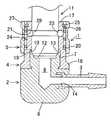
【図1】 本発明の実施の形態の一例における接続状態を示す断面図である。
【図2】 図1の接続前の状態を示す断面図である。
【図3】従来一例を示す断面図である。
【符号の説明】
1 透析器接続用カプラ
2 本体
3 ライン接続体
4 連結筒
5 固定機構
9 液体移送路
10 プラグ用開口部
11 接続プラグ
12,13 第1・第2シール面
16 固着部
17 連結部[0001]
BACKGROUND OF THE INVENTION
TECHNICAL FIELD The present invention relates to a dialyzer connection coupler for connecting a liquid transfer line such as a dialysate circulation hose to a connection plug (dialyte fluid inlet / outlet) of a dialyzer.
[0002]
[Prior art]
As a dialyzer connection coupler for connecting a liquid transfer line such as a dialysate circulation hose to a connection plug of a dialyzer such as a dialyzer, for example, there is the one shown in FIG. In this structure, a
[0003]
By the way, in recent years, there is a concern about the risk of exothermic substances such as endotoxin entering the blood from the dialysate due to the improvement in substance permeation performance due to high performance of the dialyzer. For this reason, there is an increasing need to clean the dialysate, and RO water (water treated with a reverse osmosis membrane) is used when preparing the actual dialysate, and the endotoxin removal filter is dialyzed during dialysis. Various devices have been made, such as being installed in front of the vessel.
[0004]
[Problems to be solved by the invention]
However, even if the dialysate is sufficiently cleaned as described above, when the connection coupler shown in FIG. 3 is used as a connection coupler connected to the connection plug of the dialyzer, Bacteria were generated, and endotoxin was liberated from these bacteria and could enter the dialysate. The main cause is that when the connection plug and the connection coupler are connected, a dead space (gap) is formed in the peripheral portion of the O-
[0005]
An object of the present invention is to provide a coupler for connecting a dialyzer that can solve the above problems.
[0006]
[Means for Solving the Problems]
In order to achieve the above object, the present invention is characterized by A. It is integrally formed in a hollow shape with an elastic material, the inside itself is used as a liquid transfer path, and the plug opening of the liquid transfer path opens at the tip surface, and the tip of the connection plug of the dialyzer is in this plug opening A body that is relatively removably inserted; A line connection body that isformed of a metal material or a synthetic resin material , is a member different from the main body, is inserted into the main body, communicates with the liquid transfer path inside, and is connected to the liquid transfer line; C.It is formed of a metal material or a synthetic resin material , is a member different from the main body, is formed in a cylindrical shape, and is fixed to the front end portion of the main body, and is fixed to the front end in the axial direction from the fixed portion. A connecting cylinder having a connecting portion projectingly provided and detachably fitted to a portion of the connecting plug excluding the tip thereof;It is made of a metal material or a synthetic resin material , and has a fixing mechanism for releasably fixing the connecting tube to the connection plug in a state where the main body is pressed to the connection plug side, and the plug opening portion is a plug in the liquid transfer path. The bottom surface of the inner surface of the plug opening is elastically deformed toward the base side of the main body by direct contact with the connection plug when the connection plug is connected, is a first sealing surface which is in close contact with the distal end surface and a liquid-tight state of the connection plug, the side surface of the plug opening inner surface iscontinuously providedwith respect to the inner surface of the connecting portion of the consolidated tube, when connecting the connection plug, a connection Due to the direct contact with the plug, it is elastically deformed radially outward to form a second seal surface that is in close contact with the side surface of the tip of the connection plug in a liquid-tight state.
[0007]
DETAILED DESCRIPTION OF THE INVENTION
Hereinafter, an example of an embodiment of the present invention will be described based on the drawings of FIGS. 1 to 2. A dialyzer connection coupler 1 includes a
[0008]
The
[0009]
The
[0010]
The connecting
[0011]
The
[0012]
Each
[0013]
The
[0014]
The
[0015]
The
[0016]
According to the above configuration example, the connection coupler 1 is in the state shown in FIG. 2 when not connected to the connection plug 11 of the dialyzer. During dialysis, a dialysate circulation hose is connected to the
[0017]
At this time, the
[0018]
As described above, the front end portion of the
[0019]
Next, when the pressing ofthe
[0020]
When releasing the connection between the connection coupler 1 and the
[0021]
According to the above configuration example, the
[0022]
Further, since no O-ring or the like is used as in the prior art, there is no problem that a dead space (gap) in which the dialysate stays is formed around the O-ring as in the prior art. . Further, the inner surface of the connecting
[0023]
Further, in the connecting coupler 1, a connecting
[0024]
【The invention's effect】
As described above in detail, according to the present invention, the connection coupler can be securely connected to the connection plug in a liquid-tight state, and bacteria are unlikely to be generated in the connection coupler. There is little possibility that exothermic substances such as the like will enter the dialysate. Moreover, the use of connection couplers long time, the coupling tube or the line connection and the like fear Re also less to distorted, the connecting coupler itself isnot small also a danger ofdeforming.
[Brief description of the drawings]
FIG. 1 is a cross-sectional view showing aconnection state in an exampleof an embodiment of the present invention.
FIG. 2is a cross-sectional viewshowing a state before connection in FIG.
FIG. 3 is a cross-sectional view showing a conventional example.
[Explanation of symbols]
DESCRIPTION OF SYMBOLS 1 Coupler for
Claims (1)
Translated fromJapaneseB.金属材料又は合成樹脂材料により形成されて、本体とは別の部材とされ、本体内に 挿着されて、内部が液体移送路と連通すると共に、液体移送ラインが接続されるライ ン接続体と、
C.金属材料又は合成樹脂材料により形成され、本体とは別の部材とされて、筒状に形 成されており、本体の先端部に外嵌固着される固着部と、固着部から軸心方向前方に 突設され且つ接続プラグにおける、その先端部を除く部分に嵌脱自在に外嵌される連 結部を有する連結筒と、
D.金属材料又は合成樹脂材料により形成され、本体を接続プラグ側に押圧した状態で 、連結筒を接続プラグに解除可能に固定する固定機構
を有し、
プラグ用開口部が、液体移送路における、プラグ用開口部と隣接する部分よりも大径とされ、
プラグ用開口部内面の底面が、
・ 接続プラグの接続時に、接続プラグとの直接の当接により、本体の基部側に弾性変 形して、接続プラグの先端面と液密状態で密着する第1シール面
とされ、
プラグ用開口部内面の側面が、
・ 連結筒の連結部の内面に対して連設され、接続プラグの接続時に、接続プラグとの 直接の当接により、径方向外方に弾性変形して、接続プラグの先端部の側面と液密状 態で密着する第2シール面
とされた透析器接続用カプラ。A. It is integrally formed in a hollow shape by an elastic material, and the inside itself is used as a liquid transfer path, and a plug opening of the liquid transfer path is opened at the distal end surface, and the tip of the connection plug of the dialyzer is inserted into the plug opening. A main body in which the part is relatively removably inserted,
B. A line connection body that isformed of a metal material or a synthetic resin material , is a member different from the main body, is inserted into the main body, communicates with the liquid transfer path, and is connected to the liquid transfer line. ,
C.It is formed of a metal material or a synthetic resin material , is a member different from the main body, isformed in a cylindrical shape, and is fixed to the front end portion of the main body. A connecting cylinder that protrudes forward in the direction and has a connecting portion that is detachably fitted to a portion of the connecting plug excluding its tip,
D.It is formed of a metal material or a synthetic resin material , and has a fixing mechanism for releasably fixing the connecting tube to the connection plug in a state where the main body is pressed toward the connection plug.
The plug opening is larger in diameter than the portion adjacent to the plug opening in the liquid transfer path,
The bottom of the inner surface of the plug opening
-When the connection plug is connected, it is elastically deformed to the base side of the main body by direct contact with the connection plug, and the first seal surface is brought into close contact with the front end surface of the connection plug in a liquid-tight state.
The side of the inner surface of the plug opening
- providedcontinuously with respect to the inner surface of the connecting portion of the connecting tube, at the time of connection of the connection plug, by direct contact of the connection plug, is elastically deformed outward in the radial direction, the side surface and the liquid of the tip portion of the connection plug A coupler for dialyzer connection, which is a second sealing surface that is in close contact with each other.
Priority Applications (5)
| Application Number | Priority Date | Filing Date | Title |
|---|---|---|---|
| JP2003174029AJP4286073B2 (en) | 2003-06-18 | 2003-06-18 | Coupler for dialyzer connection |
| AT04014045TATE413900T1 (en) | 2003-06-18 | 2004-06-16 | COUPLING FOR CONNECTING TO A DIALYZER |
| DE602004017670TDE602004017670D1 (en) | 2003-06-18 | 2004-06-16 | Coupling for connection to a dialyzer |
| EP04014045AEP1488825B1 (en) | 2003-06-18 | 2004-06-16 | Dialyzer connecting coupler |
| US10/869,043US7017948B2 (en) | 2003-06-18 | 2004-06-17 | Dialyzer connecting coupler |
Applications Claiming Priority (1)
| Application Number | Priority Date | Filing Date | Title |
|---|---|---|---|
| JP2003174029AJP4286073B2 (en) | 2003-06-18 | 2003-06-18 | Coupler for dialyzer connection |
Related Child Applications (1)
| Application Number | Title | Priority Date | Filing Date |
|---|---|---|---|
| JP2007020918ADivisionJP2007105543A (en) | 2007-01-31 | 2007-01-31 | Coupler for dialyzer connection |
Publications (2)
| Publication Number | Publication Date |
|---|---|
| JP2005006860A JP2005006860A (en) | 2005-01-13 |
| JP4286073B2true JP4286073B2 (en) | 2009-06-24 |
Family
ID=33410965
Family Applications (1)
| Application Number | Title | Priority Date | Filing Date |
|---|---|---|---|
| JP2003174029AExpired - LifetimeJP4286073B2 (en) | 2003-06-18 | 2003-06-18 | Coupler for dialyzer connection |
Country Status (5)
| Country | Link |
|---|---|
| US (1) | US7017948B2 (en) |
| EP (1) | EP1488825B1 (en) |
| JP (1) | JP4286073B2 (en) |
| AT (1) | ATE413900T1 (en) |
| DE (1) | DE602004017670D1 (en) |
Families Citing this family (34)
| Publication number | Priority date | Publication date | Assignee | Title |
|---|---|---|---|---|
| DE10352859B3 (en)* | 2003-11-10 | 2005-06-02 | Fresenius Medical Care Deutschland Gmbh | Connector for dialyzer port |
| DK176145B1 (en)* | 2004-09-23 | 2006-10-02 | Guldmann V As | Clutch |
| US10537671B2 (en) | 2006-04-14 | 2020-01-21 | Deka Products Limited Partnership | Automated control mechanisms in a hemodialysis apparatus |
| US9717834B2 (en) | 2011-05-24 | 2017-08-01 | Deka Products Limited Partnership | Blood treatment systems and methods |
| US8273049B2 (en) | 2007-02-27 | 2012-09-25 | Deka Products Limited Partnership | Pumping cassette |
| US7794141B2 (en) | 2006-04-14 | 2010-09-14 | Deka Products Limited Partnership | Thermal and coductivity sensing systems, devices and methods |
| US8425471B2 (en) | 2007-02-27 | 2013-04-23 | Deka Products Limited Partnership | Reagent supply for a hemodialysis system |
| KR102444304B1 (en) | 2007-02-27 | 2022-09-19 | 데카 프로덕츠 리미티드 파트너쉽 | hemodialysis system |
| US8393690B2 (en) | 2007-02-27 | 2013-03-12 | Deka Products Limited Partnership | Enclosure for a portable hemodialysis system |
| US8357298B2 (en) | 2007-02-27 | 2013-01-22 | Deka Products Limited Partnership | Hemodialysis systems and methods |
| US8562834B2 (en) | 2007-02-27 | 2013-10-22 | Deka Products Limited Partnership | Modular assembly for a portable hemodialysis system |
| US9028691B2 (en) | 2007-02-27 | 2015-05-12 | Deka Products Limited Partnership | Blood circuit assembly for a hemodialysis system |
| US8491184B2 (en) | 2007-02-27 | 2013-07-23 | Deka Products Limited Partnership | Sensor apparatus systems, devices and methods |
| US8409441B2 (en) | 2007-02-27 | 2013-04-02 | Deka Products Limited Partnership | Blood treatment systems and methods |
| US8042563B2 (en) | 2007-02-27 | 2011-10-25 | Deka Products Limited Partnership | Cassette system integrated apparatus |
| US20090107335A1 (en) | 2007-02-27 | 2009-04-30 | Deka Products Limited Partnership | Air trap for a medical infusion device |
| US8771508B2 (en)* | 2008-08-27 | 2014-07-08 | Deka Products Limited Partnership | Dialyzer cartridge mounting arrangement for a hemodialysis system |
| US11738130B2 (en) | 2008-01-23 | 2023-08-29 | Deka Products Limited Partnership | Fluid line autoconnect apparatus and methods for medical treatment system |
| US11833281B2 (en) | 2008-01-23 | 2023-12-05 | Deka Products Limited Partnership | Pump cassette and methods for use in medical treatment system using a plurality of fluid lines |
| US8708950B2 (en) | 2010-07-07 | 2014-04-29 | Deka Products Limited Partnership | Medical treatment system and methods using a plurality of fluid lines |
| WO2010009395A1 (en)* | 2008-07-18 | 2010-01-21 | Clark Equipment Company | Integral 90 degree fitting hydraulic quick coupler and attachments and work machines employing the same |
| CN104841030B (en) | 2009-10-30 | 2017-10-31 | 德卡产品有限公司 | For the apparatus and method for the disconnection for detecting intravascular access device |
| US8505955B2 (en)* | 2010-02-11 | 2013-08-13 | Remark Technologies, Inc. | Coupling device and method |
| EP3205362B1 (en) | 2011-05-24 | 2022-07-06 | DEKA Products Limited Partnership | Hemodialysis system |
| JP2014527881A (en) | 2011-09-21 | 2014-10-23 | ベイヤー メディカル ケア インク. | Continuous multi-fluid pump device, drive and actuation system and method |
| US20130136532A1 (en)* | 2011-11-28 | 2013-05-30 | Tsun-Chi Liao | Cymbal quick-release structure |
| EP2827039A1 (en)* | 2013-07-17 | 2015-01-21 | Volvo Car Corporation | Quick connector |
| CN104208765B (en)* | 2014-08-15 | 2016-02-17 | 袁毅强 | A kind of haemodialysis control unit joint sterilization combination |
| US10507319B2 (en) | 2015-01-09 | 2019-12-17 | Bayer Healthcare Llc | Multiple fluid delivery system with multi-use disposable set and features thereof |
| WO2017100621A1 (en) | 2015-12-11 | 2017-06-15 | Nxstage Medical, Inc. | Fluid line connector devices methods and systems |
| JP6393725B2 (en)* | 2016-10-25 | 2018-09-19 | 日機装株式会社 | Blood purification device and coupler |
| FR3061258B1 (en)* | 2016-12-23 | 2019-05-31 | Staubli Faverges | FEMALE CONNECTING ELEMENT, TO BE FITTED WITH AN ADDITIONAL MALE ELEMENT AND CONNECTION COMPRISING SUCH A FEMALE ELEMENT |
| US11333282B2 (en) | 2019-11-05 | 2022-05-17 | Diality Inc. | Locking connector |
| DE102022101299A1 (en) | 2022-01-20 | 2023-07-20 | B.Braun Avitum Ag | Extracorporeal blood treatment machine with operating device |
Family Cites Families (14)
| Publication number | Priority date | Publication date | Assignee | Title |
|---|---|---|---|---|
| US2518542A (en)* | 1948-07-21 | 1950-08-15 | Fred E Hansen | Steam hose coupling |
| US2631872A (en)* | 1949-01-24 | 1953-03-17 | Franklin T Wurmser | Quick coupling |
| US3334860A (en)* | 1964-07-13 | 1967-08-08 | Jr Cecil G Bolton | Fluid coupling |
| US4496458A (en)* | 1977-05-23 | 1985-01-29 | Extracorporeal Medical Specialties, Inc. | Dialysis apparatus and technique |
| US4198080A (en)* | 1978-05-19 | 1980-04-15 | Baxter Travenol Laboratories, Inc. | Telescoping-type connector |
| DE8519806U1 (en)* | 1985-07-09 | 1985-08-14 | B. Braun Melsungen Ag, 3508 Melsungen | Connection device |
| US5052725A (en)* | 1989-03-13 | 1991-10-01 | Colder Products Company | Two piece molded female coupling |
| JP2758148B2 (en)* | 1995-08-14 | 1998-05-28 | 日機装株式会社 | Blood purifier coupler |
| BR9600812A (en)* | 1996-02-26 | 1997-12-23 | Tampas Click Ltda | Quick connector |
| JPH1170163A (en)* | 1997-06-18 | 1999-03-16 | Kawasumi Lab Inc | Coupler connector for hemodialyzer |
| JP3300889B2 (en)* | 1998-06-29 | 2002-07-08 | 株式会社メテク | Dialyzer aseptic connection socket |
| DE60011359T2 (en)* | 1999-09-27 | 2005-06-16 | Legris S.A. | Device for connecting a line end to a connection part |
| JP3235064B2 (en)* | 2000-02-16 | 2001-12-04 | 株式会社メテク | Sterile coupler for dialyzer connection |
| EP1488826A1 (en)* | 2003-06-19 | 2004-12-22 | Nipro Corporation | Dialyzer-connecting coupler joint |
- 2003
- 2003-06-18JPJP2003174029Apatent/JP4286073B2/ennot_activeExpired - Lifetime
- 2004
- 2004-06-16EPEP04014045Apatent/EP1488825B1/ennot_activeExpired - Lifetime
- 2004-06-16DEDE602004017670Tpatent/DE602004017670D1/ennot_activeExpired - Lifetime
- 2004-06-16ATAT04014045Tpatent/ATE413900T1/ennot_activeIP Right Cessation
- 2004-06-17USUS10/869,043patent/US7017948B2/ennot_activeExpired - Fee Related
Also Published As
| Publication number | Publication date |
|---|---|
| DE602004017670D1 (en) | 2008-12-24 |
| JP2005006860A (en) | 2005-01-13 |
| US7017948B2 (en) | 2006-03-28 |
| EP1488825A1 (en) | 2004-12-22 |
| ATE413900T1 (en) | 2008-11-15 |
| US20040262917A1 (en) | 2004-12-30 |
| EP1488825B1 (en) | 2008-11-12 |
Similar Documents
| Publication | Publication Date | Title |
|---|---|---|
| JP4286073B2 (en) | Coupler for dialyzer connection | |
| JP6242823B2 (en) | Tube connection structure | |
| US9492649B2 (en) | Set of easily cleanable connectors for a liquid circuit | |
| US4391274A (en) | Filtered hub device for aspirating and injecting liquids | |
| JP2758148B2 (en) | Blood purifier coupler | |
| KR20160003782A (en) | Container | |
| CN114555145B (en) | Pressure cartridge holder for extracorporeal blood therapy machines | |
| JP2007105543A (en) | Coupler for dialyzer connection | |
| US10279158B2 (en) | Disposable connector for hemofiltration | |
| JP4415134B2 (en) | Coupler coupler and coupler used in the coupler coupler | |
| US6971680B2 (en) | Dialysis coupler assembly with joint members and hemodialysis system using same | |
| JP4352771B2 (en) | Coupler coupler and coupler equipped with the coupler coupler | |
| JPS5810030A (en) | Change-over operation apparatus for endoscope | |
| JP2018198835A (en) | Coupler for blood purifier | |
| JP3887816B2 (en) | A pair of interconnectable couplers | |
| JP2008079794A (en) | Joint for extracorporeal circulation module and medical adapter using the joint | |
| JP4356534B2 (en) | Coupler joint for dialyzer connection | |
| JP4051709B2 (en) | coupler | |
| JP2005040393A (en) | Coupler for blood dialyzer | |
| JPS6223489Y2 (en) | ||
| JP2000107285A (en) | Coupler | |
| JPH0513454U (en) | Medical connection protector | |
| JP2012192062A (en) | Dialyzing coupler | |
| JPH0733301U (en) | Cover type endoscope | |
| JPH0560735B2 (en) |
Legal Events
| Date | Code | Title | Description |
|---|---|---|---|
| A977 | Report on retrieval | Free format text:JAPANESE INTERMEDIATE CODE: A971007 Effective date:20060228 | |
| A131 | Notification of reasons for refusal | Free format text:JAPANESE INTERMEDIATE CODE: A131 Effective date:20060418 | |
| A521 | Request for written amendment filed | Free format text:JAPANESE INTERMEDIATE CODE: A523 Effective date:20060602 | |
| A02 | Decision of refusal | Free format text:JAPANESE INTERMEDIATE CODE: A02 Effective date:20061212 | |
| A521 | Request for written amendment filed | Free format text:JAPANESE INTERMEDIATE CODE: A523 Effective date:20070131 | |
| A911 | Transfer to examiner for re-examination before appeal (zenchi) | Free format text:JAPANESE INTERMEDIATE CODE: A911 Effective date:20070216 | |
| A912 | Re-examination (zenchi) completed and case transferred to appeal board | Free format text:JAPANESE INTERMEDIATE CODE: A912 Effective date:20070316 | |
| A521 | Request for written amendment filed | Free format text:JAPANESE INTERMEDIATE CODE: A523 Effective date:20090217 | |
| A01 | Written decision to grant a patent or to grant a registration (utility model) | Free format text:JAPANESE INTERMEDIATE CODE: A01 | |
| A61 | First payment of annual fees (during grant procedure) | Free format text:JAPANESE INTERMEDIATE CODE: A61 Effective date:20090324 | |
| FPAY | Renewal fee payment (event date is renewal date of database) | Free format text:PAYMENT UNTIL: 20120403 Year of fee payment:3 | |
| R150 | Certificate of patent or registration of utility model | Ref document number:4286073 Country of ref document:JP Free format text:JAPANESE INTERMEDIATE CODE: R150 Free format text:JAPANESE INTERMEDIATE CODE: R150 | |
| FPAY | Renewal fee payment (event date is renewal date of database) | Free format text:PAYMENT UNTIL: 20120403 Year of fee payment:3 | |
| FPAY | Renewal fee payment (event date is renewal date of database) | Free format text:PAYMENT UNTIL: 20150403 Year of fee payment:6 | |
| R250 | Receipt of annual fees | Free format text:JAPANESE INTERMEDIATE CODE: R250 | |
| R250 | Receipt of annual fees | Free format text:JAPANESE INTERMEDIATE CODE: R250 | |
| R250 | Receipt of annual fees | Free format text:JAPANESE INTERMEDIATE CODE: R250 | |
| R250 | Receipt of annual fees | Free format text:JAPANESE INTERMEDIATE CODE: R250 | |
| R250 | Receipt of annual fees | Free format text:JAPANESE INTERMEDIATE CODE: R250 | |
| EXPY | Cancellation because of completion of term |