JP4285532B2 - Backlight control device, backlight control method, and liquid crystal display device - Google Patents
Backlight control device, backlight control method, and liquid crystal display deviceDownload PDFInfo
- Publication number
- JP4285532B2 JP4285532B2JP2006325781AJP2006325781AJP4285532B2JP 4285532 B2JP4285532 B2JP 4285532B2JP 2006325781 AJP2006325781 AJP 2006325781AJP 2006325781 AJP2006325781 AJP 2006325781AJP 4285532 B2JP4285532 B2JP 4285532B2
- Authority
- JP
- Japan
- Prior art keywords
- backlight
- luminance
- ratio
- value
- liquid crystal
- Prior art date
- Legal status (The legal status is an assumption and is not a legal conclusion. Google has not performed a legal analysis and makes no representation as to the accuracy of the status listed.)
- Expired - Fee Related
Links
- 239000004973liquid crystal related substanceSubstances0.000titleclaimsdescription104
- 238000000034methodMethods0.000titleclaimsdescription19
- 230000000007visual effectEffects0.000claimsdescription11
- 230000008859changeEffects0.000claimsdescription10
- 230000008569processEffects0.000claimsdescription9
- 235000019557luminanceNutrition0.000description208
- 238000002834transmittanceMethods0.000description14
- 238000012937correctionMethods0.000description13
- 101100084404Mus musculus Prodh geneProteins0.000description5
- 238000010586diagramMethods0.000description5
- 239000002131composite materialSubstances0.000description3
- 239000000470constituentSubstances0.000description3
- 230000002093peripheral effectEffects0.000description3
- 239000000758substrateSubstances0.000description3
- 239000008186active pharmaceutical agentSubstances0.000description2
- 230000003287optical effectEffects0.000description2
- 230000035699permeabilityEffects0.000description2
- 230000035945sensitivityEffects0.000description2
- 101150004094PRO2 geneProteins0.000description1
- 239000013078crystalSubstances0.000description1
- 238000009792diffusion processMethods0.000description1
- 238000011156evaluationMethods0.000description1
- 230000006870functionEffects0.000description1
- 238000012986modificationMethods0.000description1
- 230000004048modificationEffects0.000description1
- 238000005192partitionMethods0.000description1
- 230000008447perceptionEffects0.000description1
- 238000012545processingMethods0.000description1
- 230000004044responseEffects0.000description1
- 230000011218segmentationEffects0.000description1
- 230000001953sensory effectEffects0.000description1
- 239000007787solidSubstances0.000description1
- 230000001629suppressionEffects0.000description1
- 239000010409thin filmSubstances0.000description1
Images


Classifications
- G—PHYSICS
- G09—EDUCATION; CRYPTOGRAPHY; DISPLAY; ADVERTISING; SEALS
- G09G—ARRANGEMENTS OR CIRCUITS FOR CONTROL OF INDICATING DEVICES USING STATIC MEANS TO PRESENT VARIABLE INFORMATION
- G09G3/00—Control arrangements or circuits, of interest only in connection with visual indicators other than cathode-ray tubes
- G09G3/20—Control arrangements or circuits, of interest only in connection with visual indicators other than cathode-ray tubes for presentation of an assembly of a number of characters, e.g. a page, by composing the assembly by combination of individual elements arranged in a matrix no fixed position being assigned to or needed to be assigned to the individual characters or partial characters
- G09G3/34—Control arrangements or circuits, of interest only in connection with visual indicators other than cathode-ray tubes for presentation of an assembly of a number of characters, e.g. a page, by composing the assembly by combination of individual elements arranged in a matrix no fixed position being assigned to or needed to be assigned to the individual characters or partial characters by control of light from an independent source
- G09G3/3406—Control of illumination source
- G09G3/342—Control of illumination source using several illumination sources separately controlled corresponding to different display panel areas, e.g. along one dimension such as lines
- G09G3/3426—Control of illumination source using several illumination sources separately controlled corresponding to different display panel areas, e.g. along one dimension such as lines the different display panel areas being distributed in two dimensions, e.g. matrix
- G—PHYSICS
- G02—OPTICS
- G02F—OPTICAL DEVICES OR ARRANGEMENTS FOR THE CONTROL OF LIGHT BY MODIFICATION OF THE OPTICAL PROPERTIES OF THE MEDIA OF THE ELEMENTS INVOLVED THEREIN; NON-LINEAR OPTICS; FREQUENCY-CHANGING OF LIGHT; OPTICAL LOGIC ELEMENTS; OPTICAL ANALOGUE/DIGITAL CONVERTERS
- G02F1/00—Devices or arrangements for the control of the intensity, colour, phase, polarisation or direction of light arriving from an independent light source, e.g. switching, gating or modulating; Non-linear optics
- G02F1/01—Devices or arrangements for the control of the intensity, colour, phase, polarisation or direction of light arriving from an independent light source, e.g. switching, gating or modulating; Non-linear optics for the control of the intensity, phase, polarisation or colour
- G02F1/13—Devices or arrangements for the control of the intensity, colour, phase, polarisation or direction of light arriving from an independent light source, e.g. switching, gating or modulating; Non-linear optics for the control of the intensity, phase, polarisation or colour based on liquid crystals, e.g. single liquid crystal display cells
- G02F1/133—Constructional arrangements; Operation of liquid crystal cells; Circuit arrangements
- G—PHYSICS
- G09—EDUCATION; CRYPTOGRAPHY; DISPLAY; ADVERTISING; SEALS
- G09G—ARRANGEMENTS OR CIRCUITS FOR CONTROL OF INDICATING DEVICES USING STATIC MEANS TO PRESENT VARIABLE INFORMATION
- G09G2320/00—Control of display operating conditions
- G09G2320/02—Improving the quality of display appearance
- G09G2320/0233—Improving the luminance or brightness uniformity across the screen
- G—PHYSICS
- G09—EDUCATION; CRYPTOGRAPHY; DISPLAY; ADVERTISING; SEALS
- G09G—ARRANGEMENTS OR CIRCUITS FOR CONTROL OF INDICATING DEVICES USING STATIC MEANS TO PRESENT VARIABLE INFORMATION
- G09G2320/00—Control of display operating conditions
- G09G2320/02—Improving the quality of display appearance
- G09G2320/028—Improving the quality of display appearance by changing the viewing angle properties, e.g. widening the viewing angle, adapting the viewing angle to the view direction
- G—PHYSICS
- G09—EDUCATION; CRYPTOGRAPHY; DISPLAY; ADVERTISING; SEALS
- G09G—ARRANGEMENTS OR CIRCUITS FOR CONTROL OF INDICATING DEVICES USING STATIC MEANS TO PRESENT VARIABLE INFORMATION
- G09G2330/00—Aspects of power supply; Aspects of display protection and defect management
- G09G2330/02—Details of power systems and of start or stop of display operation
- G09G2330/021—Power management, e.g. power saving
- G—PHYSICS
- G09—EDUCATION; CRYPTOGRAPHY; DISPLAY; ADVERTISING; SEALS
- G09G—ARRANGEMENTS OR CIRCUITS FOR CONTROL OF INDICATING DEVICES USING STATIC MEANS TO PRESENT VARIABLE INFORMATION
- G09G2360/00—Aspects of the architecture of display systems
- G09G2360/16—Calculation or use of calculated indices related to luminance levels in display data
Landscapes
- Physics & Mathematics (AREA)
- Engineering & Computer Science (AREA)
- General Physics & Mathematics (AREA)
- Theoretical Computer Science (AREA)
- Computer Hardware Design (AREA)
- Nonlinear Science (AREA)
- Crystallography & Structural Chemistry (AREA)
- Optics & Photonics (AREA)
- Chemical & Material Sciences (AREA)
- Mathematical Physics (AREA)
- Liquid Crystal Display Device Control (AREA)
- Control Of Indicators Other Than Cathode Ray Tubes (AREA)
- Liquid Crystal (AREA)
Description
Translated fromJapanese本発明は、バックライト制御装置、バックライト制御方法、および液晶表示装置に関し、特に、斜め方向から見たときの輝度ムラを防止することができるようにするバックライト制御装置、バックライト制御方法、および液晶表示装置に関する。 The present invention relates to a backlight control device, a backlight control method, and a liquid crystal display device, and more particularly, a backlight control device, a backlight control method, and a backlight control device that can prevent luminance unevenness when viewed from an oblique direction. And a liquid crystal display device.
液晶表示装置(LCD: Liquid crystal display)は、赤色、緑色、および青色の着色がされているカラーフィルタ基板や液晶層などを有する液晶パネルと、その背面側に配置されるバックライトなどにより構成される。 A liquid crystal display (LCD) is composed of a color filter substrate colored with red, green and blue, a liquid crystal panel having a liquid crystal layer, etc., and a backlight arranged on the back side thereof. The
液晶表示装置では、電圧を変化させることにより液晶層の液晶分子のねじれが制御され、液晶分子のねじれに応じて液晶層を透過してきたバックライトの白色光が赤色、緑色、または青色のカラーフィルタを通過することにより赤色、緑色、または青色の光となって、画像が表示される。 In the liquid crystal display device, the twist of the liquid crystal molecules in the liquid crystal layer is controlled by changing the voltage, and the white light of the backlight transmitted through the liquid crystal layer according to the twist of the liquid crystal molecules is a red, green, or blue color filter By passing through, the light becomes red, green, or blue light, and an image is displayed.
なお、以下では、電圧を変化させることにより液晶分子のねじれを制御して光の透過率を変更することを、液晶開口率の制御という。また、光源であるバックライトから出射され、液晶層に入射される光の輝度を「バックライト輝度」と称し、液晶表示装置に表示された画像を視認する視聴者が感じる光の強度である、液晶パネルの前面から出射された光の輝度を「表示輝度」と称する。 In the following, changing the light transmittance by controlling the twist of the liquid crystal molecules by changing the voltage is referred to as controlling the liquid crystal aperture ratio. In addition, the luminance of light emitted from the backlight, which is a light source, and incident on the liquid crystal layer is referred to as “backlight luminance”, and is the intensity of light that is perceived by the viewer viewing the image displayed on the liquid crystal display device. The luminance of light emitted from the front surface of the liquid crystal panel is referred to as “display luminance”.
従来、液晶表示装置においては、バックライトが液晶パネルの画面全体を均一かつ最大の明るさで照明し、液晶パネルの各画素の液晶開口率のみを制御することによって、画面の各画素において必要な表示輝度を得るような制御が行われていた。従って、例えば、画面全体が暗い場合においても、バックライトは最大のバックライト輝度で発光するので、消費電力が大きい、およびコントラスト比が低いという問題があった。 Conventionally, in a liquid crystal display device, the backlight illuminates the entire screen of the liquid crystal panel with uniform and maximum brightness, and only the liquid crystal aperture ratio of each pixel of the liquid crystal panel is controlled, so that it is necessary for each pixel of the screen. Control was performed to obtain display brightness. Therefore, for example, even when the entire screen is dark, the backlight emits light with the maximum backlight luminance, so that there are problems that the power consumption is large and the contrast ratio is low.
この問題に対して、例えば、画面を複数の領域に分割し、その分割された領域単位でバックライト輝度を制御することが提案されている(例えば、特許文献1,2参照)。 To solve this problem, for example, it has been proposed to divide the screen into a plurality of areas and control the backlight luminance in units of the divided areas (see, for example,
このようなバックライト分割制御について、図1乃至図3を参照して説明する。 Such backlight division control will be described with reference to FIGS.
図1は、液晶表示装置に表示させる原画像P1を示している。原画像P1は、略中央部に楕円形状の最も暗い領域R1があり、領域R1から外周側になるほど徐々に明るい画像となっている。但し、暗い領域R1から外周方向に対する輝度の変化率は図面下方向よりも図面上方向の方が大きい。 FIG. 1 shows an original image P1 displayed on the liquid crystal display device. The original image P1 has the darkest region R1 having an elliptical shape at a substantially central portion, and the image gradually becomes brighter from the region R1 toward the outer peripheral side. However, the rate of change in luminance from the dark region R1 to the outer peripheral direction is larger in the upper direction than in the lower direction in the drawing.
図2は、バックライトの構造を簡略化して示した図である。 FIG. 2 is a diagram showing a simplified structure of the backlight.
図2に示されるバックライトでは、点灯領域が、水平方向(横方向)に4分割、垂直方向(縦方向)に6分割されることにより、24分割されている。 In the backlight shown in FIG. 2, the lighting region is divided into 24 parts by dividing into 4 parts in the horizontal direction (lateral direction) and 6 parts in the vertical direction (vertical direction).
バックライトが原画像P1に対応する発光を行う場合、バックライトは、原画像P1の領域R1の輝度に応じて、網掛けされている2つの領域のバックライト輝度を抑制して点灯する(減光する)。 When the backlight emits light corresponding to the original image P1, the backlight is turned on by reducing the backlight luminance of the two shaded areas according to the luminance of the area R1 of the original image P1. Light up).
その結果、図3に示すように、バックライト全体では、図1の原画像P1に対して、点灯領域の略中央部が最も暗く、外周方向にいくに従って均一に明るくなる輝度分布を得ることができる。このように、バックライトの一部を減光することにより、消費電力を低減するとともに、表示輝度のダイナミックレンジを拡大することができる。 As a result, as shown in FIG. 3, with respect to the original backlight as a whole, a luminance distribution can be obtained in which the substantially central portion of the lighting region is the darkest and becomes uniformly brighter in the outer peripheral direction with respect to the original image P1 of FIG. it can. In this way, by reducing part of the backlight, power consumption can be reduced and the dynamic range of display luminance can be expanded.
なお、点灯領域の分割数は、通常、液晶パネルの画素数よりも少ないので、図1の原画像P1の輝度分布と図3のバックライト輝度分布とが一致することはなく、例えば、図3のQQ’線上の画素のように、原画像P1の輝度が一定でもバックライト輝度が異なる画素が多々発生する。QQ’線上の画素に対して、バックライト分割制御では、液晶開口率がバックライト分割制御をしないときのそれよりも大きく、より光を透過するように設定される。このように、液晶開口率をバックライト分割制御しない時の設定から変更することによって、バックライト輝度の抑制した分を補った、いわば液晶開口率制御によって見かけ上発光させた輝度を、液晶補正輝度という。 Since the number of divisions of the lighting region is usually smaller than the number of pixels of the liquid crystal panel, the luminance distribution of the original image P1 in FIG. 1 does not match the backlight luminance distribution in FIG. Like the pixels on the QQ 'line, there are many pixels with different backlight luminance even if the luminance of the original image P1 is constant. With respect to the pixels on the QQ ′ line, in the backlight division control, the liquid crystal aperture ratio is set to be larger than that in the case where the backlight division control is not performed, so that more light is transmitted. In this way, by changing the liquid crystal aperture ratio from the setting when the backlight division control is not performed, the amount of light that is apparently emitted by the liquid crystal aperture ratio control, which compensates for the suppression of the backlight luminance, is corrected to the liquid crystal correction luminance. That's it.
図4は、バックライト分割制御におけるバックライト輝度と液晶補正輝度の関係を示す概念図である。 FIG. 4 is a conceptual diagram showing a relationship between backlight luminance and liquid crystal correction luminance in backlight division control.
バックライト分割制御のバックライト制御部は、所定の領域において同一の表示輝度T0を実現するために、バックライト輝度分布MBLに対して、液晶補正輝度分布MCLが逆の分布となるように、液晶開口率を制御する。このとき、液晶開口率をいくつに設定すると液晶補正輝度がどれだけになるかは、図5に示す液晶の透過率特性によって決定される。The backlight control unit of the backlight division control is configured such that the liquid crystal correction luminance distribution MCL is opposite to the backlight luminance distribution MBL in order to achieve the same display luminance T0 in a predetermined region. In addition, the liquid crystal aperture ratio is controlled. At this time, how much the liquid crystal aperture ratio is set and how much the liquid crystal correction luminance is set is determined by the transmittance characteristic of the liquid crystal shown in FIG.
なお、通常、液晶の透過率特性は、液晶表示装置の画面を正面から見たときを基準にするので、図5に示す透過率特性も、画面を正面から見たとき(以下、0度の方向ともいう)のものであり、予め評価および決定された特性である。 In general, the transmittance characteristics of the liquid crystal are based on the time when the screen of the liquid crystal display device is viewed from the front. Therefore, the transmittance characteristics shown in FIG. 5 are also when the screen is viewed from the front (hereinafter referred to as 0 degree). (Also referred to as direction), which is a property that has been evaluated and determined in advance.
ところで、液晶表示装置の画面に表示された画像を、ユーザは常に正面から見るとは限らないので、斜めから見たときについて考えてみると、液晶には視野角特性があるので、当然ながら、画面を見るときの角度(視野角)によって液晶の透過率特性は異なる。液晶表示装置の正面から水平方向に移動し、画面を45度の方向から見たときの透過率特性を、図5に示した0度の方向の透過率特性に重ねた図を図6に示す。 By the way, since the user does not always see the image displayed on the screen of the liquid crystal display device from the front, when viewing from an oblique direction, the liquid crystal has a viewing angle characteristic. The transmittance characteristics of the liquid crystal vary depending on the angle when viewing the screen (viewing angle). FIG. 6 is a diagram in which the transmittance characteristics when moving in the horizontal direction from the front of the liquid crystal display device and viewing the screen from the 45 degree direction are superimposed on the transmittance characteristics in the 0 degree direction shown in FIG. .
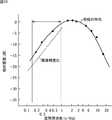
図6の横軸は、液晶の透過率を設定する8ビットの設定値である設定階調を表し、縦軸は、所定のバックライト輝度における各設定階調の輝度を表す。また、図7は、図6の0度の方向と45度の方向の輝度を比較するための、45度の方向から見たときの輝度を0度の方向から見たときの輝度で除算して得られる、0度と45度との輝度比を示している。 The horizontal axis in FIG. 6 represents a set gradation which is an 8-bit set value for setting the transmittance of the liquid crystal, and the vertical axis represents the brightness of each set gradation at a predetermined backlight brightness. Further, FIG. 7 divides the luminance when viewed from the 45 degree direction by the luminance when viewed from the 0 degree direction for comparing the luminance in the 0 degree direction and the 45 degree direction of FIG. The luminance ratio between 0 degree and 45 degrees obtained in this way is shown.
図6および図7を参照して分かるように、α点より低い設定階調では、0度よりも45度から見た方が輝度(透過率)が高くなり、1階調変化するごとの輝度比の変化率も大きい。一方、α点より高い設定階調では、逆に45度よりも0度から見た方が輝度が高くなり、1階調変化するごとの輝度比の変化率は、低階調側よりも小さい。なお、液晶の透過率特性は、VA(Vertical Alignment)、IPS(In-Plane-Switching)などの液晶モードによっても異なるので、図6および図7に示す特性がすべてではない。As can be seen with reference to FIG. 6 and FIG. 7, in the set gradation lower than the α point, the luminance (transmittance) is higher when viewed from 45 degrees than 0 degrees, and the luminance every time one gradation is changed. The rate of change of the ratio is large. On the other hand, at the set gradation higher than the α point, the luminance is higher when viewed from 0 degree than 45 degrees, and the change rate of the luminance ratio for every change of one gradation is smaller than that at the low gradation side. . Note that the transmittance characteristics of the liquid crystal vary depending on the liquid crystal mode such as VA (Vertical Alignment) and IPS (In-Plane- Switching), and thus the characteristics shown in FIGS. 6 and 7 are not all.
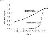
図4に示したバックライト輝度と液晶補正輝度の関係は、通常、画面を0度の方向から見たときの液晶の透過率特性を基準に計算されている。そこで、図6に点線で示した45度の方向の液晶の透過率特性に基づいて、45度の方向から見た場合の液晶補正輝度分布MCL’を求めると、図8に示すようになる。The relationship between the backlight luminance and the liquid crystal correction luminance shown in FIG. 4 is normally calculated based on the transmittance characteristics of the liquid crystal when the screen is viewed from the 0 degree direction. Therefore, when the liquid crystal correction luminance distribution MCL ′ when viewed from the 45 ° direction is obtained based on the transmittance characteristic of the liquid crystal in the 45 ° direction indicated by the dotted line in FIG. 6, it is as shown in FIG. .
図8において、液晶補正輝度が最小な画素(バックライト輝度が最大の画素)は、図6および図7において0度と45度のいずれの方向から見ても輝度差がないα点に対応する画素xαであり、そのときのバックライト輝度がBLα、液晶補正輝度がLCαである。また、画素xα以外の画素の設定階調は、α点の設定階調よりも大きい値が設定されているものとする。In FIG. 8, the pixel having the minimum liquid crystal correction luminance (the pixel having the maximum backlight luminance) corresponds to the α point where there is no luminance difference when viewed from either 0 ° or 45 ° in FIGS. The pixel xα is a backlight luminance at that time, BLα , and the liquid crystal correction luminance is LCα . Further, it is assumed that the set gradation of pixels other than the pixel xα is set to a value larger than the set gradation of the α point.
この場合、画素xα以外の画素では、45度の液晶補正輝度分布MCL’は、0度の液晶補正輝度分布MCLよりも低くなる。その結果、45度の方向から見たときの表示輝度は、太線の点線で示されるように、画素xα以外の画素で、液晶補正輝度分布MCLと液晶補正輝度分布MCL’との差だけ、目標の表示輝度T0よりも異なる。In this case, the pixels other than the pixel xalpha, 45 ° crystal corrected luminance distribution MCL of 'is lower than the liquid crystal correction luminance distribution MCL of 0 degrees. As a result, the display luminance when viewed from the direction of 45 degrees is the difference between the liquid crystal correction luminance distribution MCL and the liquid crystal correction luminance distribution MCL ′ in the pixels other than the pixel xα as indicated by the thick dotted line. Only different from the target display brightness T0 .
即ち、同一の表示輝度T0となるように制御しているにもかかわらず、ユーザが45度の方向から画面を見たときには、画素xα以外の画素において、バックライト輝度の輝度分布MBLに応じた表示輝度の差が発生し、その差の最大値ΔTと表示輝度T0との比ΔT/T0が大きい場合には、輝度ムラとして見えるようになる。That is, when the user views the screen from the direction of 45 degrees despite the control to have the same display luminance T0 , the luminance distribution MBL of the backlight luminance in the pixels other than the pixel xα. difference in display luminance is generated in response to, when the ratio [Delta] T / T0 of the display luminance T0 to the maximum value [Delta] T of the difference is large, becomes visible as luminance unevenness.
本発明は、このような状況に鑑みてなされたものであり、斜め方向から見たときの輝度ムラを防止することができるようにするものである。 The present invention has been made in view of such a situation, and is intended to prevent uneven brightness when viewed from an oblique direction.
本発明の第1の側面のバックライト制御装置は、液晶表示装置に使用されるバックライトであって、点灯領域が複数のブロックに分割され、分割された前記ブロックそれぞれでバックライト輝度を個別に変えることが可能なバックライトを制御するバックライト制御装置において、隣接する前記ブロックどうしの前記バックライト設定値の比であるバックライト点灯比から1を引いた差の絶対値が第1の値以下となるように、各ブロックの前記バックライト輝度を算出し、算出された前記バックライト輝度となるように前記バックライトを制御するバックライト制御手段を備え、前記バックライト点灯比の臨界値である第1の値は、前記点灯領域上において輝度の差を比較するため予め設定された所定の間隔離れた画素どうしの前記バックライト輝度の比から1を引いた差の絶対値が、第2の値以下であるという条件から算出され、前記所定の間隔離れた画素どうしの前記バックライト輝度の比の臨界値である第2の値は、予め設定された最大隣接輝度比から1を引いた差の絶対値であり、前記最大隣接輝度比は、人間の視覚特性により前記所定の間隔離れた画素どうしの輝度差を認識できないという条件を満たす値である。A backlight control device according to a first aspect of the present invention is a backlight used in a liquid crystal display device, wherein a lighting region is divided into a plurality of blocks, and the backlight luminance is individually set in each of the divided blocks. In a backlight control device that controls a changeable backlight, an absolute value of a difference obtained by subtracting 1 from a backlight lighting ratio that is a ratio of the backlight setting values of adjacent blocks is equal to or less than a first value as a, calculates the backlight brightness of each block, a backlight control unit that controls the backlight such that the calculated the backlight luminanceis the critical value of the backlight lighting ratio The first value is the value of the backlight of pixels separated by a predetermined interval set in advance to compare the difference in luminance on the lighting area. The absolute value of the difference obtained by subtracting 1 from the brightness ratio is less than or equal to the second value, and is a second value that is the critical value of the backlight brightness ratio between the pixels that are separated by the predetermined interval. Is the absolute value of the difference obtained by subtracting 1 from the preset maximum adjacent luminance ratio, and the maximum adjacent luminance ratio cannot recognize the luminance difference between the pixels separated by the predetermined interval due to human visual characteristics. It is a value that satisfies the condition .
前記所定の間隔離れた第1の画素x1と第2の画素x2に対して、前記第1の画素x1のバックライト輝度BLx1と液晶開口率LCx1の乗算値から、前記第2の画素x2のバックライト輝度BLx2と液晶開口率LCx2の乗算値を引いた差を、前記バックライト輝度BLx1と液晶開口率LCx1の乗算値で除算した値の絶対値で求められるエラー率の前記点灯領域内の最大値と、前記人間が前記所定の間隔離れた画素どうしで輝度差があると認識してしまう最低の輝度比である認知可能最低輝度変化レベルとの乗算結果以下となる値とすることができる。For the first pixel x1 and the second pixel x2 that are separated from each other by a predetermined distance, the back of the second pixel x2 is calculated from the multiplication value of the backlight luminance BLx1 of the first pixel x1 and the liquid crystal aperture ratio LCx1. The maximum value in the lighting area of the error rate obtained by the absolute value of the difference obtained by subtracting the multiplication value of the light luminance BLx2 and the liquid crystal aperture ratio LCx2 by the multiplication value of the backlight luminance BLx1 and the liquid crystal aperture ratio LCx1 And a value that isequal to or lower than the result of multiplication by the lowest recognizable luminance change level, which is the lowest luminance ratio that the human recognizes as having a luminance difference between the pixels that are separated by the predetermined interval .
本発明の第1の側面のバックライト制御方法は、液晶表示装置に使用されるバックライトであって、点灯領域が複数のブロックに分割され、分割された前記ブロックそれぞれでバックライト輝度を個別に変えることが可能なバックライトを制御するバックライト制御処理を行うバックライト制御方法において、隣接する前記ブロックどうしの前記バックライトの設定値の比であるバックライト点灯比から1を引いた差の絶対値が第1の値以下となるように、各ブロックの前記バックライト輝度を算出し、算出された前記バックライト輝度となるように前記バックライトを制御するステップを含み、前記バックライト点灯比の臨界値である第1の値は、前記点灯領域上において輝度の差を比較するため予め設定された所定の間隔離れた画素どうしの前記バックライト輝度の比から1を引いた差の絶対値が、第2の値以下であるという条件から算出され、前記所定の間隔離れた画素どうしの前記バックライト輝度の比の臨界値である第2の値は、予め設定された最大隣接輝度比から1を引いた差の絶対値であり、前記最大隣接輝度比は、人間の視覚特性により前記所定の間隔離れた画素どうしの輝度差を認識できないという条件を満たす値である。A backlight control method according to a first aspect of the present invention is a backlight used in a liquid crystal display device, wherein a lighting area is divided into a plurality of blocks, and the backlight luminance is individually set in each of the divided blocks. In a backlight control method for performing a backlight control process for controlling a backlight that can be changed, an absolute value of a difference obtained by subtracting 1 from a backlight lighting ratio that is a ratio of a set value of the backlight between adjacent blocks so that the value is equal to or less thana first value, and calculates the backlight brightness of each block,look including the step of controlling the backlight such that the calculated the backlightbrightness, the backlight lighting ratio The first value which is the critical value of the pixel is a pixel value which is separated by a predetermined interval for comparing the difference in luminance on the lighting region. Calculated from the condition that the absolute value of the difference obtained by subtracting 1 from the backlight luminance ratio is less than or equal to a second value, and is a critical value of the ratio of the backlight luminance between pixels that are separated by the predetermined interval. A certain second value is an absolute value of a difference obtained by subtracting 1 from a preset maximum adjacent luminance ratio, and the maximum adjacent luminance ratio is a luminance difference between pixels separated by the predetermined interval due to human visual characteristics. Is a value that satisfies the condition that cannot be recognized .
本発明の第2の側面の液晶表示装置は、点灯領域が複数のブロックに分割され、分割された前記ブロックそれぞれでバックライト輝度を個別に変えることが可能なバックライトと、隣接する前記ブロックどうしの前記バックライトの設定値の比であるバックライト点灯比から1を引いた差の絶対値が第1の値以下となるように、各ブロックの前記バックライト輝度を算出し、算出された前記バックライト輝度となるように前記バックライトを制御するバックライト制御手段とを備え、前記バックライト点灯比の臨界値である第1の値は、前記点灯領域上において輝度の差を比較するため予め設定された所定の間隔離れた画素どうしの前記バックライト輝度の比から1を引いた差の絶対値が、第2の値以下であるという条件から算出され、前記所定の間隔離れた画素どうしの前記バックライト輝度の比の臨界値である第2の値は、予め設定された最大隣接輝度比から1を引いた差の絶対値であり、前記最大隣接輝度比は、人間の視覚特性により前記所定の間隔離れた画素どうしの輝度差を認識できないという条件を満たす値である。In the liquid crystal display device according to the second aspect of the present invention, a lighting region is divided into a plurality of blocks, and a backlight capable of individually changing a backlight luminance in each of the divided blocks, and adjacent blocks. The backlight luminance of each block is calculated so that the absolute value ofthe difference obtained by subtracting 1 from the backlight lighting ratio, which is the ratio of the backlight setting value, is equal to or less thanthe first value, and the calculated Backlight control means for controlling the backlightso as to obtain backlight luminance, and the first value which is a critical value of the backlight lighting ratio is preliminarily compared with the luminance difference on the lighting region. The absolute value of the difference obtained by subtracting 1 from the ratio of the backlight luminance between pixels set at predetermined intervals is less than or equal to a second value, A second value that is a critical value of the ratio of the backlight luminance between pixels that are separated by a fixed interval is an absolute value of a difference obtained by subtracting 1 from a preset maximum adjacent luminance ratio, and the maximum adjacent luminance ratio Is a value that satisfies the condition that the luminance difference between pixels separated by the predetermined interval cannot be recognized due to human visual characteristics .
本発明の第1および第2の側面においては、隣接するブロックどうしのバックライトの設定値の比であるバックライト点灯比から1を引いた差の絶対値が第1の値以下となるように、各ブロックのバックライト輝度が算出され、その算出されたバックライト輝度となるようにバックライトが制御される。ここで、バックライト点灯比の臨界値である第1の値は、点灯領域上において輝度の差を比較するため予め設定された所定の間隔離れた画素どうしのバックライト輝度の比から1を引いた差の絶対値が、第2の値以下であるという条件から算出され、所定の間隔離れた画素どうしのバックライト輝度の比の臨界値である第2の値は、予め設定された最大隣接輝度比から1を引いた差の絶対値であり、最大隣接輝度比は、人間の視覚特性により所定の間隔離れた画素どうしの輝度差を認識できないという条件を満たす値である。In the first and second aspects of the present invention, an absolute value of a difference obtained by subtracting 1 from a backlight lighting ratio, which is a ratio of setting values of backlights between adjacent blocks, is equal to or less thanthe first value. The backlight luminance of each block is calculated, and the backlight is controlled so as to be the calculated backlight luminance.Here, the first value, which is a critical value of the backlight lighting ratio, is obtained by subtracting 1 from the ratio of the backlight luminance between pixels set at a predetermined interval in order to compare the luminance difference on the lighting region. The second value, which is calculated from the condition that the absolute value of the difference is less than or equal to the second value and is the critical value of the ratio of the backlight luminance between pixels that are separated by a predetermined distance, is the maximum adjacent value set in advance. The absolute value of the difference obtained by subtracting 1 from the luminance ratio, and the maximum adjacent luminance ratio is a value that satisfies the condition that the luminance difference between pixels separated by a predetermined interval cannot be recognized due to human visual characteristics.
本発明の第1および第2の側面によれば、消費電力を低減するとともに、表示輝度のダイナミックレンジを拡大することができる。 According to the first and second aspects of the present invention, the power consumption can be reduced and the dynamic range of display luminance can be expanded.
また、本発明の第1および第2の側面によれば、斜め方向から見たときの輝度ムラを防止することができる。 In addition, according to the first and second aspects of the present invention, luminance unevenness when viewed from an oblique direction can be prevented.
以下に本発明の実施の形態を説明するが、本発明の構成要件と、明細書又は図面に記載の実施の形態との対応関係を例示すると、次のようになる。この記載は、本発明をサポートする実施の形態が、明細書又は図面に記載されていることを確認するためのものである。従って、明細書又は図面中には記載されているが、本発明の構成要件に対応する実施の形態として、ここには記載されていない実施の形態があったとしても、そのことは、その実施の形態が、その構成要件に対応するものではないことを意味するものではない。逆に、実施の形態が構成要件に対応するものとしてここに記載されていたとしても、そのことは、その実施の形態が、その構成要件以外の構成要件には対応しないものであることを意味するものでもない。 Embodiments of the present invention will be described below. Correspondences between the constituent elements of the present invention and the embodiments described in the specification or the drawings are exemplified as follows. This description is intended to confirm that the embodiments supporting the present invention are described in the specification or the drawings. Therefore, even if there is an embodiment which is described in the specification or the drawings but is not described here as an embodiment corresponding to the constituent elements of the present invention, that is not the case. It does not mean that the form does not correspond to the constituent requirements. Conversely, even if an embodiment is described here as corresponding to a configuration requirement, that means that the embodiment does not correspond to a configuration requirement other than the configuration requirement. Not something to do.
本発明の第1の側面のバックライト制御装置は、液晶表示装置に使用されるバックライトであって、点灯領域が複数のブロックに分割され、分割された前記ブロックそれぞれでバックライト輝度を個別に変えることが可能なバックライトを制御するバックライト制御装置(例えば、図9の制御部13)において、隣接する前記ブロックどうしの前記バックライト設定値の比であるバックライト点灯比から1を引いた差の絶対値が第1の値以下となるように、各ブロックの前記バックライト輝度を算出し、算出された前記バックライト輝度となるように前記バックライトを制御するバックライト制御手段(例えば、図9の光源制御部32)を備え、前記バックライト点灯比の臨界値である第1の値は、前記点灯領域上において輝度の差を比較するため予め設定された所定の間隔離れた画素どうしの前記バックライト輝度の比から1を引いた差の絶対値が、第2の値以下であるという条件から算出され、前記所定の間隔離れた画素どうしの前記バックライト輝度の比の臨界値である第2の値は、予め設定された最大隣接輝度比から1を引いた差の絶対値であり、前記最大隣接輝度比は、人間の視覚特性により前記所定の間隔離れた画素どうしの輝度差を認識できないという条件を満たす値である。A backlight control device according to a first aspect of the present invention is a backlight used in a liquid crystal display device, wherein a lighting area is divided into a plurality of blocks, and the backlight luminance is individually set in each of the divided blocks. In a backlight control device (for example, the
本発明の第1の側面のバックライト制御方法は、液晶表示装置に使用されるバックライトであって、点灯領域が複数のブロックに分割され、分割された前記ブロックそれぞれでバックライト輝度を個別に変えることが可能なバックライトを制御するバックライト制御処理を行うバックライト制御方法において、隣接する前記ブロックどうしの前記バックライトの設定値の比であるバックライト点灯比から1を引いた差の絶対値が所定の値以下となるように、各ブロックの前記バックライト輝度を算出し(例えば、図19のステップS13)、算出された前記バックライト輝度となるように前記バックライトを制御する(例えば、図19のステップS16)ステップを含み、前記バックライト点灯比の臨界値である第1の値は、前記点灯領域上において輝度の差を比較するため予め設定された所定の間隔離れた画素どうしの前記バックライト輝度の比から1を引いた差の絶対値が、第2の値以下であるという条件から算出され、前記所定の間隔離れた画素どうしの前記バックライト輝度の比の臨界値である第2の値は、予め設定された最大隣接輝度比から1を引いた差の絶対値であり、前記最大隣接輝度比は、人間の視覚特性により前記所定の間隔離れた画素どうしの輝度差を認識できないという条件を満たす値である。A backlight control method according to a first aspect of the present invention is a backlight used in a liquid crystal display device, wherein a lighting area is divided into a plurality of blocks, and the backlight luminance is individually set in each of the divided blocks. In a backlight control method for performing a backlight control process for controlling a backlight that can be changed, an absolute value of a difference obtained by subtracting 1 from a backlight lighting ratio that is a ratio of a set value of the backlight between adjacent blocks The backlight luminance of each block is calculated so that the value is equal to or less than a predetermined value (for example, step S13 in FIG. 19), and the backlight is controlled so as to be the calculated backlight luminance (for example, ,look including the step S16) step of FIG.19, the first value is a critical value of the backlight ratio, said lighting region In order to compare the luminance difference, the absolute value of the difference obtained by subtracting 1 from the ratio of the backlight luminance between pixels set at a predetermined interval in advance is less than or equal to the second value. The second value, which is a critical value of the ratio of the backlight luminance between pixels separated by the predetermined interval, is an absolute value of a difference obtained by subtracting 1 from a preset maximum adjacent luminance ratio, and the maximum adjacent The luminance ratio is a value that satisfies the condition that the luminance difference between pixels separated by the predetermined interval cannot be recognized due to human visual characteristics .
以下、図を参照して、本発明の実施の形態について説明する。 Hereinafter, embodiments of the present invention will be described with reference to the drawings.
図9は、本発明を適用した液晶表示装置の一実施の形態の構成例を示している。 FIG. 9 shows a configuration example of an embodiment of a liquid crystal display device to which the present invention is applied.
図9の液晶表示装置1は、赤色、緑色、および青色の着色がされているカラーフィルタ基板、液晶層などを有する液晶パネル11、液晶パネル11の背面側に配置されるバックライト12、並びに、液晶パネル11およびバックライト12を制御する制御部13により構成されている。 9 includes a color filter substrate colored red, green, and blue, a
液晶表示装置1は、入力される画像信号に対応する原画像を所定の表示領域(表示部21)に表示する。なお、液晶表示装置1に入力される画像信号は、例えば、60Hzのフレームレートの画像(以下、フィールド画像という)に対応する。 The liquid
液晶パネル11は、バックライト12からの光を透過させる開口部が複数配列されている表示部21、並びに、表示部21の開口部それぞれに設けられている図示しないトランジスタ(TFT:Thin Film Transistor)に駆動信号を送出するソースドライバ22およびゲートドライバ23により構成されている。 The
なお、開口部を通過した光は、図示せぬカラーフィルタ基板上に形成されている赤色、緑色、または青色のカラーフィルタによって赤色、緑色、または青色の光に変換される。この赤色、緑色、および青色の光を発する3つの開口部からなる組が表示部21の1画素に対応し、赤色、緑色、または青色の光を発する各開口部は、画素を構成する副画素となる。 The light that has passed through the opening is converted into red, green, or blue light by a red, green, or blue color filter that is formed on a color filter substrate (not shown). A set of three openings that emit red, green, and blue light corresponds to one pixel of the
バックライト12は、表示部21に対応する点灯領域において白色の光を発する。バックライト12の点灯領域は複数のブロック(領域)に分割されており、分割された複数のブロックそれぞれについて個別に点灯が制御される。 The
本実施の形態では、バックライト12の点灯領域は、水平方向および垂直方向のいずれにおいても22分割され、全部で484ブロックに分割されていることとして説明する。なお、図9においては、紙面の制約上、水平方向に5分割、垂直方向に6分割したバックライト12の例を示している。 In the present embodiment, the lighting area of the
ブロックAi,jに配置されている光源LTi,jは、例えば、所定の順序で配列された赤色、緑色、および青色の光を発するLED(Light Emitting Diode:発光ダイオード)により構成される。光源LTi,jは、光源制御部32から供給される制御信号に基づいて、赤色、緑色、および青色の混合により得られる白色の光を発する。The light source LTi, j arranged in the block Ai, j is configured by, for example, LEDs (Light Emitting Diodes) that emit red, green, and blue light arranged in a predetermined order. The light source LTi, j emits white light obtained by mixing red, green, and blue based on a control signal supplied from the light
なお、ブロックAi,jは、バックライト12の点灯領域を、仕切り板等を用いて物理的に分割したものではなく、光源LTi,jに対応する領域として仮想的に分割したものである。従って、光源LTi,jから出射された光は、図示しない拡散板によって拡散されて、光源LTi,jの前面に配置するブロックAi,jだけでなく、その周辺のブロックに対しても照射される。Note that the block Ai, j is not obtained by physically dividing the lighting area of the
制御部13は、表示輝度算出部31、光源制御部32、および液晶パネル制御部33により構成される。制御部13は、液晶パネル11を制御する液晶パネル制御装置、および、バックライト12を制御するバックライト制御装置として機能する。 The
表示輝度算出部31には、フィールド画像に対応する画像信号が他の装置から供給される。表示輝度算出部31は、供給された画像信号からフィールド画像の輝度分布を求め、さらにフィールド画像の輝度分布から、ブロックAi,jで必要な表示輝度PNi,jを算出する。算出された表示輝度PNi,jは、光源制御部32および液晶パネル制御部33に供給される。The display
光源制御部32は、表示輝度算出部31から供給されたブロックAi,jの表示輝度PNi,jから、バックライト輝度BLi,jを決定する。光源制御部32は、バックライト輝度BLi,jを決定する際、表示部21の各画素において、自身(画素x1とする)のバックライト輝度BLx1と所定の間隔DSだけ離れた画素x2のバックライト輝度BLx2(≦BLx1)の比(隣接輝度比)c=BLx1/BLx2(≧1)が最大隣接輝度比Cmax以下となるように、バックライト輝度BLi,jを算出し、液晶パネル制御部33に供給する。The light
ここで、最大隣接輝度比Cmaxは、「最大隣接輝度比Cmax ≦ 最大エラー率εmax×認知可能最低輝度変化レベル」という、輝度ムラが、例えば、斜め方向から見るなどしても、ユーザ(人間)の視覚特性で認知できないレベルに抑えるための条件に基づいて算出された値である。Here, the maximum adjacent luminance ratio Cmax is equal to “maximum adjacent luminance ratio Cmax ≦ maximum error rateεmax × recognizable minimum luminance change level”. ) Is a value calculated based on a condition for suppressing the level to a level that cannot be recognized by visual characteristics.
また、「最大エラー率εmax」は、バックライト12の点灯領域内の上述の画素x1とx2の液晶開口率をそれぞれLCx1およびLCx2としたとき、|(BLx1×LCx1−BLx2×LCx2)/(BLx1×LCx1)|で求められるエラー率εの最大値である。「最大エラー率εmax」の要因としては、1)液晶の視野角特性、2)液晶と拡散板との間の間隔による視差、3)演算精度、等があり、それらのうちの最大のものによって「最大エラー率εmax」が支配される。The “maximum error rate εmax ” is | (BLx1 × LCx1−BLx2 × LCx2) / (when the liquid crystal aperture ratios of the pixels x1 and x2 in the lighting region of the
「認知可能最低輝度変化レベル」は、官能評価によって得られた、ユーザ(人間の目)が輝度に差がある(輝度ムラがある)と認識してしまう輝度比である。人間の視覚などの知覚が刺激値の「差」ではなく「比」で応答することはウェーバーの法則にもあるように自明であり、また、図10において点線で示されるように、隣接輝度比cは、等しい振幅に対し、空間周波数が高くなると比例して増加し、相対感度も、矢印で示される所定の空間周波数の範囲では、空間周波数に比例して増加するので、結局、隣接輝度比cは、空間周波数に拠らず、一定の弁別閾を持つことになる。従って、各ブロックによるバックライト輝度の輝度分布がどのような形状をしている場合であっても、「認知可能最低輝度変化レベル」を一定の値として定義することができる。 The “recognizable minimum luminance change level” is a luminance ratio obtained by sensory evaluation that allows the user (human eye) to recognize that there is a difference in luminance (there is luminance unevenness). It is self-evident that perception such as human vision responds with a “ratio” rather than a “difference” in stimulus values, as is also in Weber's law, and as shown by a dotted line in FIG. For the same amplitude, c increases in proportion to an increase in spatial frequency, and the relative sensitivity also increases in proportion to the spatial frequency in a predetermined spatial frequency range indicated by an arrow. c does not depend on the spatial frequency and has a certain discrimination threshold. Therefore, the “recognizable minimum luminance change level” can be defined as a constant value regardless of the shape of the luminance distribution of the backlight luminance by each block.
以上のように、光源制御部32は、「最大隣接輝度比Cmax ≦ 最大エラー率εmax×認知可能最低輝度変化レベル」に基づいて、隣接輝度比cが最大隣接輝度比Cmax以下であることを満足するようなバックライト輝度BLi,jを算出するが、バックライト12の制御単位はブロックなので、隣接輝度比cが最大隣接輝度比Cmax以下の条件を満足する、隣接するブロックどうしの光源設定値の比(隣接ブロック点灯比)rの最小値(最小隣接ブロック点灯比)Rに換算する必要がある。最大隣接輝度比Cmaxから最小隣接ブロック点灯比Rの求め方については、図18を参照して後述するが、光源制御部32は、隣接輝度比cが最大隣接輝度比Cmax以下となる最小隣接ブロック点灯比Rを求め、最小隣接ブロック点灯比Rを満足するようにバックライト輝度BLi,jを算出する。なお、最小隣接ブロック点灯比R(0<R<1)は、隣接するブロックどうしの表示輝度に大きな差がある場合であっても最低必要な隣接ブロック点灯比であり、隣接するブロックどうしの表示輝度に差がない場合には、隣接ブロック点灯比rが最小隣接ブロック点灯比R以上となることもある(最小隣接ブロック点灯比R以上となることは構わない)。As described above, the light
そして、光源制御部32はPAM(Pulse Amplitude Modulation)制御か、または、PWM(Pulse Width Modulation)制御により、算出されたバックライト輝度BLi,jとなるように制御する。このような、最小隣接ブロック点灯比R以上とするようにバックライト輝度BLi,jを制御することを隣接間制御と呼ぶことにする。本実施の形態では、例えば、間隔DSは7.45mmとし、そのときの最大隣接輝度比Cmaxは1.02である。また、Cmax=1.02に対応する最小隣接ブロック点灯比Rは、0.88となる。Then, the light
液晶パネル制御部33は、表示輝度算出部31からの表示輝度PNi,jと光源制御部32からのバックライト輝度BLi,jに基づいて、表示部21の各画素の液晶開口率を決定する。そして、液晶パネル制御部33は、決定された液晶開口率となるように、液晶パネル11のソースドライバ22およびゲートドライバ23に駆動制御信号を供給し、表示部21の各画素のTFTを駆動制御する。The liquid crystal
図11乃至図14を参照して、光源制御部32による隣接間制御についてさらに説明する。 The adjacent control by the light
図11は、1ブロックの光源、例えば、点灯領域の中央のブロックA11,11に注目し、その注目ブロックA11,11の光源LT11,11を単独で発光させた場合のバックライト輝度の輝度分布(以下、プロファイルともいう)Proを示している。なお、図11乃至図14においては、水平方向の一列(j=11)のブロックAi,11についてのみ説明するので、j=11の表記は省略する。FIG. 11 shows a backlight luminance when one light source, for example, the block A11,11 at the center of the lighting area is focused and the light source LT11,11 of thetarget block A11,11 is caused to emit light alone. The luminance distribution (hereinafter also referred to as profile) Pro is shown. In FIG. 11 to FIG. 14, only the block Ai, 11 in one horizontal row (j = 11) will be described, and the description of j = 11 is omitted.
図12に示すように、注目ブロックA11の光源LT11を、あるバックライト輝度BL1で発光させるようにすると、隣接間制御では、隣接ブロック点灯比を注目ブロックA11の光源LT11に対する設定値を基準(1)として最小隣接ブロック点灯比Rに設定するので、その両隣のブロックA10およびA12は、バックライト輝度(BL1×R)で発光させる必要があり、ブロックA9およびブロックA13は、バックライト輝度(BL1×R2)で発光させる必要がある。従って、図11に示した光源LT11単独でのプロファイルProと最小隣接ブロック点灯比Rが決まると、注目ブロックA11を中心とする合成プロファイルPro1が必然的に決定される。As shown in FIG. 12, a light source LT11 of the block of interest A11, when so as to emit light at a certain backlight luminance BL1, the adjacent between the control, set the neighbor block lighting ratio with respect to the light source LT11 of the block of interest A11 value Is set to the minimum adjacent block lighting ratio R with reference to (1), the adjacent blocks A10 and A12 need to emit light with backlight luminance (BL1 × R), and the blocks A9 and A13 Needs to emit light with backlight luminance (BL1 × R2 ). Therefore, when the determined profile Pro and the minimum neighboring block lighting ratio R at the light sourceLT11 alone as shown in FIG. 11, the synthetic profile Pro1 centering on the target block A11 is inevitably determined.
そこで、例えば、図13に示すように、注目ブロックA11の表示輝度PN11が、バックライト分割制御を行わず、各ブロックAi,jにおいて同一の100%の出力で、液晶開口率を100%として発光させたときの表示輝度に等しい、バックライト12が発光することができる最大の表示輝度(以下、適宜、ピーク輝度という)PNPKで、同列のその他のブロックA9,A10,A12、およびA13の表示輝度PN9,PN10,PN12、およびPN13が0である場合、光源制御部32は、図14に示すように、注目ブロックA11の全ての画素がピーク輝度PNPKを満足する合成プロファイルPro2となるように、合成プロファイルPro1をオフセットさせるドライブ倍率K11を算出すればよい。ここで、ドライブ倍率K11は、上述のピーク輝度PNPKを基準(1)として決定される値であり、注目ブロックA11の周辺のブロックA9,A10,A12,A13・・のバックライト輝度を下げて、注目ブロックA11の全画素がピーク輝度PNPKを満足するためには、注目ブロックA11の設定値を、バックライト分割制御を行わない時よりも大きくする必要があるので、ドライブ倍率K11は、1(100%)以上の値となる。但し、点灯領域の全ブロックのドライブ倍率Kijが同時に1以上となることはない。Therefore, for example, as shown in FIG. 13, the display luminance PN11 of the block of interest A11 is, without backlight division control, the blocks Ai, the same 100% output atj, the liquid
図15乃至図17に、具体的な数値例を示す。 Specific examples of numerical values are shown in FIGS.
図15は、ブロックA11の光源LT11を単独で発光させた場合の実際のプロファイルProを示している。Figure 15 shows the actual profile Pro when light is emitted to the light source LT11 of the block A11 alone.
なお、図15の縦軸は、ピーク輝度PNPKを基準輝度(PNPK=1)としたときの相対値で表される相対輝度を表す。また、プロファイルProは、ブロックA11を中心として対称な曲線で表されるので、ブロックA6乃至A10と反対側(図中右側)のプロファイルの図示は省略されている。Note that the vertical axis in FIG. 15 represents the relative luminance expressed as a relative value when the peak luminance PNPK is set to the reference luminance (PNPK = 1). Further, since the profile Pro is represented by a symmetrical curve with the block A11 as the center, the profile on the side opposite to the blocks A6 to A10 (right side in the figure) is omitted.
図15に示すプロファイルProは、バックライト分割制御を行わず、各ブロックAi,jにおいて同一の100%の出力で点灯した時に全面均一になるように(バックライト構造を含む)光学的、電流値(PAM)制御、あるいはPWM制御により調整されたプロファイルであり、かつ、そのプロファイルの最大バックライト輝度が、相対輝度で、例えば0.26となるように予め(バックライト構造を含む)光学的に設計されている。なお、プロファイルProの最大バックライト輝度は、必ずしも0.26である必要はないが、0.20以上であることが望ましい。The profile Pro shown in FIG. 15 does not perform backlight division control, and the optical and current are uniform (including the backlight structure) so that the entire surface is uniform when the blocks Ai, j are turned on at the same 100% output. It is a profile adjusted by value (PAM) control or PWM control, and the maximum backlight luminance of the profile is a relative luminance, for example, 0.26 in advance (including the backlight structure). Designed to. Note that the maximum backlight luminance of the profile Pro is not necessarily 0.26, but is preferably 0.20 or more.
そして、図15に示すプロファイルProで発光するバックライト12の各光源LTi,jを用いて、図13に示したように、ブロックA11の表示輝度PN11がピーク輝度PNPK、水平方向のブロックA11以外のj列のブロックAi(i≠11)の表示輝度PNi(i≠11)が“0”と算出された場合に、光源制御部32が隣接間制御を実行したときの、ブロックA6乃至A10のプロファイルを図16に示す。Then, each light source LTi of the
図16において、実線の曲線で示されるプロファイルが、隣接間制御を実行したときのブロックA6乃至A10のプロファイルを示し、点線の曲線で示されるプロファイルは、隣接間制御を行わずに、ブロックA11のドライブ倍率を同様にした場合のプロファイルを示している。このときのドライブ倍率K11は、1.25である。16, the profile indicated by the solid curve shows the profile of the block A6 to A10 when executing the adjacent inter-control, profile shown by the dotted curve, without a neighbor between the control block It shows the profile in the case of the same drive ratio of a11. Drive ratio K11 in this case is 1.25.
図16に示した“隣接間制御あり”および“隣接間制御なし”のプロファイルそれぞれについて、隣接輝度比cを実際に計算した結果を図17に示す。 FIG. 17 shows the result of actually calculating the adjacent luminance ratio c for each of the profiles “with adjacent control” and “without adjacent control” shown in FIG.
図17に示されるように、“隣接間制御あり”では、隣接輝度比cがブロックA6乃至A11のいずれにおいても最大隣接輝度比Cmax=1.02以下となっており、“隣接間制御なし”では、隣接輝度比cは、ブロックA6乃至A11のほとんどの箇所で最大隣接輝度比Cmaxを大きく上回っている。As shown in FIG. 17, in the “with adjacent control”, the adjacent luminance ratio c is the maximum adjacent luminance ratio Cmax = 1.02 or less in any of the blocks A6 to A11 , and “without adjacent control”. Then, the adjacent luminance ratio c greatly exceeds the maximum adjacent luminance ratio Cmax in most places in the blocks A6 to A11 .
従って、最小隣接ブロック点灯比R=0.88とすることで、隣接輝度比cを最大隣接輝度比Cmax以下とするような制御が実現されている。 Therefore, by setting the minimum adjacent block lighting ratio R = 0.88, control is performed so that the adjacent luminance ratio c is equal to or less than the maximum adjacent luminance ratio Cmax.
次に、図18を参照して、最大隣接輝度比Cmaxから最小隣接ブロック点灯比Rの求め方について説明する。 Next, how to obtain the minimum adjacent block lighting ratio R from the maximum adjacent luminance ratio Cmax will be described with reference to FIG.
上述したように、光源LTi,j単独でのプロファイルProと最小隣接ブロック点灯比Rが決まると、合成プロファイルPro1は必然的に決定する。そこで、光源制御部32は、最小隣接ブロック点灯比Rを、複数の値に仮に決定し、決定された複数の値それぞれについての合成プロファイルPro1を求める。そして、光源制御部32は、求められた複数の合成プロファイルPro1それぞれについて、最大隣接輝度比Cmaxを算出する。As described above, when the profile Pro of the light source LTi, j alone and the minimum adjacent block lighting ratio R are determined, the composite profile Pro1 is inevitably determined. Therefore, the light
複数の値に仮に決定された最小隣接ブロック点灯比Rと、そのときの最大隣接輝度比Cmaxとを2次元座標系にプロットすると、図18に示すようになる。図18のプロット結果によれば、最小隣接ブロック点灯比R=0.60からR=0.90までの間は、最小隣接ブロック点灯比Rと最大隣接輝度比Cmaxとの間に線形な相関があるとみなすことができる。そして、その最小隣接ブロック点灯比R=0.60からR=0.90までの間に、最大隣接輝度比Cmax=1.02となるような最小隣接ブロック点灯比Rが存在するので、複数の値に仮に決定された最小隣接ブロック点灯比Rと、そのときの最大隣接輝度比Cmaxから、最大隣接輝度比Cmax=1.02とするための最小隣接ブロック点灯比Rを逆算的に求めることができる。 When the minimum adjacent block lighting ratio R temporarily determined to be a plurality of values and the maximum adjacent luminance ratio Cmax at that time are plotted in a two-dimensional coordinate system, the result is as shown in FIG. According to the plot result of FIG. 18, between the minimum adjacent block lighting ratio R = 0.60 to R = 0.90, there is a linear correlation between the minimum adjacent block lighting ratio R and the maximum adjacent luminance ratio Cmax. Can be considered. Since there is a minimum adjacent block lighting ratio R between the minimum adjacent block lighting ratio R = 0.60 and R = 0.90, the maximum adjacent luminance ratio Cmax = 1.02. The minimum adjacent block lighting ratio R for obtaining the maximum adjacent luminance ratio Cmax = 1.02 can be calculated inversely from the temporarily determined minimum adjacent block lighting ratio R and the maximum adjacent luminance ratio Cmax at that time.
次に、図19のフローチャートを参照して、液晶表示装置1の表示制御処理について説明する。 Next, display control processing of the liquid
初めに、ステップS11において、表示輝度算出部31は、他の装置から供給された画像信号を受信する。この画像信号は、1枚のフィールド画像に対応する。 First, in step S11, the display
ステップS12において、表示輝度算出部31は、フィールド画像の輝度分布を求める。また、ステップS12において、表示輝度算出部31は、フィールド画像の輝度分布から、ブロックAi,jで必要な表示輝度PNi,jを算出する。算出された表示輝度PNi,jは、光源制御部32および液晶パネル制御部33に供給される。In step S12, the display
ステップS13において、光源制御部32は、隣接ブロック点灯比rが最小隣接ブロック点灯比R以上となるように、表示輝度PNi,jからバックライト輝度BLi,jを算出する。In step S13, the light
ステップS14において、光源制御部32は、バックライト輝度BLi,jに基づいてドライブ倍率Ki,jを決定する。In step S14, the light
ステップS15において、液晶パネル制御部33は、ブロックAi,jの各画素について、表示輝度PNi,jと光源制御部32からのバックライト輝度BLi,jに基づいて、液晶開口率を決定する。In step S15, the liquid crystal
ステップS16において、光源制御部32は、ブロックAi,jのドライブ倍率Ki,jに基づいて、光源LTi,jのLEDを駆動制御する。In step S< b> 16, the light
ステップS17において、液晶パネル制御部33は、液晶パネル11のソースドライバ22およびゲートドライバ23に駆動制御信号を供給し、決定された液晶開口率となるようにブロックAi,jの各画素のTFTを駆動制御する。In step S17, the liquid crystal
ステップS18において、表示輝度算出部31は、画像信号が供給されなくなったかを判定する。ステップS18で、画像信号が供給されたと判定された場合、処理はステップS11に戻り、ステップS11乃至S18の処理が実行される。これにより、液晶表示装置1は、次のフィールド画像を表示する。 In step S18, the display
一方、ステップS18で、画像信号が供給されなくなったと判定された場合、処理は終了する。 On the other hand, if it is determined in step S18 that the image signal is no longer supplied, the process ends.
以上のように、光源制御部32が隣接間制御を実行し、隣接ブロック点灯比rが最小隣接ブロック点灯比R以上となるバックライト輝度BLi,jで点灯制御することにより、隣接輝度比cを最大隣接輝度比Cmax以下とすることができるので、液晶表示装置1に表示される画像を視聴するユーザが、画面を斜めから見た場合であっても、輝度ムラを認識することがない。従って、液晶表示装置1によれば、斜め方向から見たときの輝度ムラを防止することができる。As described above, the light
また、制御部13は、バックライト分割制御を実行するので、バックライト分割制御を行わない場合と比較して、消費電力を低減するとともに、表示輝度のダイナミックレンジを拡大することができることは勿論である。 In addition, since the
なお、隣接輝度比cを最大隣接輝度比Cmax以下とするためには、上述したように、隣接するブロックどうしの光源設定値に所定の制約を持たせることにより実現する以外に、単純に光学系のみによって実現することも可能である。 In order to set the adjacent luminance ratio c to be equal to or less than the maximum adjacent luminance ratio Cmax, as described above, the optical system is simply used in addition to providing a predetermined restriction on the light source setting value between adjacent blocks. It is also possible to realize by only.
また、隣接輝度比cを最大隣接輝度比Cmax以下とする代わりに、または、それに追加して、バックライト12の点灯領域内の画素x1とx2のバックライト輝度をBLx1およびBLx2、液晶開口率をそれぞれLCx1およびLCx2としたとき、{((BLx2−BLx1)/BLx1)/(x1−x2)}で算出される値を、所定の値(例えば、4±1(%/mm))とする制御を行うようにしてもよい。 Further, instead of or in addition to setting the adjacent luminance ratio c to be equal to or less than the maximum adjacent luminance ratio Cmax, the backlight luminance of the pixels x1 and x2 in the lighting region of the
なお、隣接ブロック点灯比rが最小隣接ブロック点灯比R以上であるという条件は、隣接ブロック点灯比rから1を引いた差の絶対値(|r−1|)が所定の値T1以下であると言い換えることができ、隣接輝度比cが最大隣接輝度比Cmax以下であるという条件は、隣接輝度比cから1を引いた差の絶対値(|c−1|)が所定の値T2以下であると言い換えることができる。値T1は、最小隣接ブロック点灯比Rから1を引いた差の絶対値であり(T1=|R−1|)、値T2は、最大隣接輝度比Cmaxから1を引いた差の絶対値である(T2=|Cmax−1|)。 The condition that the adjacent block lighting ratio r is equal to or greater than the minimum adjacent block lighting ratio R is that the absolute value (| r-1 |) of the difference obtained by subtracting 1 from the adjacent block lighting ratio r is equal to or less than a predetermined value T1. In other words, the condition that the adjacent luminance ratio c is equal to or less than the maximum adjacent luminance ratio Cmax is that the absolute value (| c-1 |) of the difference obtained by subtracting 1 from the adjacent luminance ratio c is equal to or less than a predetermined value T2. In other words. The value T1 is the absolute value of the difference obtained by subtracting 1 from the minimum adjacent block lighting ratio R (T1 = | R-1 |), and the value T2 is the absolute value of the difference obtained by subtracting 1 from the maximum adjacent luminance ratio Cmax. (T2 = | Cmax-1 |).
本明細書において、フローチャートに記述されたステップは、記載された順序に沿って時系列的に行われる処理はもちろん、必ずしも時系列的に処理されなくとも、並列的あるいは個別に実行される処理をも含むものである。 In this specification, the steps described in the flowcharts include processes that are executed in parallel or individually even if they are not necessarily processed in time series, as well as processes that are executed in time series in the described order. Is also included.
本発明の実施の形態は、上述した実施の形態に限定されるものではなく、本発明の要旨を逸脱しない範囲において種々の変更が可能である。 The embodiments of the present invention are not limited to the above-described embodiments, and various modifications can be made without departing from the scope of the present invention.
1 液晶表示装置, 12 バックライト, 13 制御部, 31 表示輝度算出部, 32 光源制御部, 33 液晶パネル制御部 DESCRIPTION OF
Claims (4)
Translated fromJapanese隣接する前記ブロックどうしの前記バックライト設定値の比であるバックライト点灯比から1を引いた差の絶対値が第1の値以下となるように、各ブロックの前記バックライト輝度を算出し、算出された前記バックライト輝度となるように前記バックライトを制御するバックライト制御手段を備え、
前記バックライト点灯比の臨界値である第1の値は、前記点灯領域上において輝度の差を比較するため予め設定された所定の間隔離れた画素どうしの前記バックライト輝度の比から1を引いた差の絶対値が、第2の値以下であるという条件から算出され、
前記所定の間隔離れた画素どうしの前記バックライト輝度の比の臨界値である第2の値は、予め設定された最大隣接輝度比から1を引いた差の絶対値であり、
前記最大隣接輝度比は、人間の視覚特性により前記所定の間隔離れた画素どうしの輝度差を認識できないという条件を満たす値である
バックライト制御装置。A backlight control device for controlling a backlight that is used in a liquid crystal display device, the lighting area is divided into a plurality of blocks, and the backlight luminance can be individually changed in each of the divided blocks. In
Calculating the backlight luminance of each block so that the absolute value of the difference obtained by subtracting 1 from the backlight lighting ratio, which is the ratio of the backlight setting values of adjacent blocks, is equal to or less than the first value; Comprising backlight control meansfor controlling the backlight so as to have the calculated backlight brightness;
The first value, which is a critical value of the backlight lighting ratio, is obtained by subtracting 1 from the ratio of the backlight luminance between pixels that are set at predetermined intervals in order to compare the luminance difference on the lighting region. Calculated from the condition that the absolute value of the difference is less than or equal to the second value,
The second value, which is a critical value of the ratio of the backlight luminance between pixels separated by the predetermined interval, is an absolute value of a difference obtained by subtracting 1 from a preset maximum adjacent luminance ratio,
The maximum adjacent luminance ratio is a value that satisfies a condition that a luminance difference between pixels separated by the predetermined interval cannot be recognized due to human visual characteristics.
Backlight control device .
請求項1に記載のバックライト制御装置。The maximum adjacent luminance ratio is calculated based on a multiplication value of the backlight luminance BLx1 of the first pixel x1 and the liquid crystal aperture ratio LCx1 with respect to the first pixel x1 and the second pixel x2 separated by the predetermined interval. The error rate obtained by the absolute value of the value obtained by dividing the difference between the backlight luminance BLx2 of the second pixel x2 and the liquid crystal aperture ratio LCx2 by the product of the backlight luminance BLx1 and the liquid crystal aperture ratio LCx1 A value that is less than or equal to the result of multiplication of the maximum value in the lighting area and the lowest recognizable luminance change level that is the lowest luminance ratio that the human recognizes as having a luminance difference between pixels that are separated by the predetermined interval. The backlight control device according to claim 1.
隣接する前記ブロックどうしの前記バックライトの設定値の比であるバックライト点灯比から1を引いた差の絶対値が第1の値以下となるように、各ブロックの前記バックライト輝度を算出し、算出された前記バックライト輝度となるように前記バックライトを制御するステップを含み、
前記バックライト点灯比の臨界値である第1の値は、前記点灯領域上において輝度の差を比較するため予め設定された所定の間隔離れた画素どうしの前記バックライト輝度の比から1を引いた差の絶対値が、第2の値以下であるという条件から算出され、
前記所定の間隔離れた画素どうしの前記バックライト輝度の比の臨界値である第2の値は、予め設定された最大隣接輝度比から1を引いた差の絶対値であり、
前記最大隣接輝度比は、人間の視覚特性により前記所定の間隔離れた画素どうしの輝度差を認識できないという条件を満たす値である
バックライト制御方法。A backlight control process for controlling a backlight that is used in a liquid crystal display device, and in which a lighting area is divided into a plurality of blocks, and the backlight brightness can be individually changed in each of the divided blocks. In the backlight control method of
The backlight luminance of each block is calculated so that the absolute value ofthe difference obtained by subtracting 1 from the backlight lighting ratio, which is the ratio of the setting values of the backlight between adjacent blocks, is equal to or less thanthe first value. And controlling the backlight to have the calculated backlight brightness,
The first value, which is a critical value of the backlight lighting ratio, is obtained by subtracting 1 from the ratio of the backlight luminance between pixels that are set at predetermined intervals in order to compare the luminance difference on the lighting region. Calculated from the condition that the absolute value of the difference is less than or equal to the second value,
The second value, which is a critical value of the ratio of the backlight luminance between pixels separated by the predetermined interval, is an absolute value of a difference obtained by subtracting 1 from a preset maximum adjacent luminance ratio,
The maximum adjacent luminance ratio is a value that satisfies a condition that a luminance difference between pixels separated by the predetermined interval cannot be recognized due to human visual characteristics.
Backlight control method .
隣接する前記ブロックどうしの前記バックライトの設定値の比であるバックライト点灯比から1を引いた差の絶対値が第1の値以下となるように、各ブロックの前記バックライト輝度を算出し、算出された前記バックライト輝度となるように前記バックライトを制御するバックライト制御手段と
を備え、
前記バックライト点灯比の臨界値である第1の値は、前記点灯領域上において輝度の差を比較するため予め設定された所定の間隔離れた画素どうしの前記バックライト輝度の比から1を引いた差の絶対値が、第2の値以下であるという条件から算出され、
前記所定の間隔離れた画素どうしの前記バックライト輝度の比の臨界値である第2の値は、予め設定された最大隣接輝度比から1を引いた差の絶対値であり、
前記最大隣接輝度比は、人間の視覚特性により前記所定の間隔離れた画素どうしの輝度差を認識できないという条件を満たす値である
液晶表示装置。A lighting area is divided into a plurality of blocks, a backlight capable of individually changing the backlight brightness in each of the divided blocks, and
The backlight luminance of each block is calculated so that the absolute value ofthe difference obtained by subtracting 1 from the backlight lighting ratio, which is the ratio of the setting values of the backlight between adjacent blocks, is equal to or less thanthe first value. Backlight control means for controlling the backlight so as to obtain the calculated backlight brightness;
With
The first value, which is a critical value of the backlight lighting ratio, is obtained by subtracting 1 from the ratio of the backlight luminance between pixels that are set at predetermined intervals in order to compare the luminance difference on the lighting region. Calculated from the condition that the absolute value of the difference is less than or equal to the second value,
The second value, which is a critical value of the ratio of the backlight luminance between pixels separated by the predetermined interval, is an absolute value of a difference obtained by subtracting 1 from a preset maximum adjacent luminance ratio,
The maximum adjacent luminance ratio is a value that satisfies a condition that a luminance difference between pixels separated by the predetermined interval cannot be recognized due to human visual characteristics.
Liquid crystal display device .
Priority Applications (6)
| Application Number | Priority Date | Filing Date | Title |
|---|---|---|---|
| JP2006325781AJP4285532B2 (en) | 2006-12-01 | 2006-12-01 | Backlight control device, backlight control method, and liquid crystal display device |
| TW096140071ATWI478136B (en) | 2006-12-01 | 2007-10-25 | Apparatus and method for controlling backlight and liquid crystal display |
| US11/986,135US8400392B2 (en) | 2006-12-01 | 2007-11-20 | Apparatus and method for controlling backlight and liquid crystal display |
| EP07023265.7AEP1936600B1 (en) | 2006-12-01 | 2007-11-30 | Apparatus and method for controlling backlight and liquid crystal display |
| KR1020070123373AKR101414940B1 (en) | 2006-12-01 | 2007-11-30 | Backlight control device and method, and liquid crystal display device |
| CN2007101875744ACN101192375B (en) | 2006-12-01 | 2007-12-03 | Apparatus and method for controlling backlight and liquid crystal display |
Applications Claiming Priority (1)
| Application Number | Priority Date | Filing Date | Title |
|---|---|---|---|
| JP2006325781AJP4285532B2 (en) | 2006-12-01 | 2006-12-01 | Backlight control device, backlight control method, and liquid crystal display device |
Publications (3)
| Publication Number | Publication Date |
|---|---|
| JP2008139569A JP2008139569A (en) | 2008-06-19 |
| JP2008139569A5 JP2008139569A5 (en) | 2008-09-04 |
| JP4285532B2true JP4285532B2 (en) | 2009-06-24 |
Family
ID=39384533
Family Applications (1)
| Application Number | Title | Priority Date | Filing Date |
|---|---|---|---|
| JP2006325781AExpired - Fee RelatedJP4285532B2 (en) | 2006-12-01 | 2006-12-01 | Backlight control device, backlight control method, and liquid crystal display device |
Country Status (6)
| Country | Link |
|---|---|
| US (1) | US8400392B2 (en) |
| EP (1) | EP1936600B1 (en) |
| JP (1) | JP4285532B2 (en) |
| KR (1) | KR101414940B1 (en) |
| CN (1) | CN101192375B (en) |
| TW (1) | TWI478136B (en) |
Cited By (2)
| Publication number | Priority date | Publication date | Assignee | Title |
|---|---|---|---|---|
| US7663364B2 (en) | 2007-02-06 | 2010-02-16 | Kabushiki Kaisha Toshiba | Magnetic resonance imaging apparatus, image processing apparatus, computer program product, and data storing method |
| US8451212B2 (en) | 2009-12-25 | 2013-05-28 | Hitachi Consumer Electronics Co., Ltd. | Display apparatus and control circuit of the same |
Families Citing this family (43)
| Publication number | Priority date | Publication date | Assignee | Title |
|---|---|---|---|---|
| JP2005321727A (en)* | 2004-05-11 | 2005-11-17 | Sony Corp | Backlight device and color liquid crystal display |
| EP1770416B1 (en)* | 2004-07-15 | 2012-02-22 | Sony Corporation | Color filter and color liquid crystal display device |
| JP5331680B2 (en) | 2006-04-20 | 2013-10-30 | ジヤンセン・フアーマシユーチカ・ナームローゼ・フエンノートシヤツプ | Inhibitors of c-fms kinase |
| JP2008076899A (en)* | 2006-09-22 | 2008-04-03 | Sony Corp | Backlight device and display device |
| JP4264560B2 (en)* | 2007-01-24 | 2009-05-20 | ソニー株式会社 | Backlight device, backlight control method, and liquid crystal display device |
| US8358307B2 (en) | 2008-04-21 | 2013-01-22 | Sharp Kabushiki Kaisha | Image processing device, display device, image processing method, program, and storage medium |
| JP5365069B2 (en)* | 2008-05-16 | 2013-12-11 | ソニー株式会社 | Liquid crystal display device and control method of liquid crystal display device |
| WO2009157221A1 (en)* | 2008-06-27 | 2009-12-30 | シャープ株式会社 | Device for controlling liquid crystal display device, liquid crystal display device, method for controlling liquid crystal display device, program, and recording medium for program |
| US8917293B2 (en) | 2008-06-27 | 2014-12-23 | Sharp Kabushiki Kaisha | Control device for liquid crystal display device, liquid crystal display device, method for controlling liquid crystal display device, program, and storage medium |
| KR100950682B1 (en)* | 2008-07-24 | 2010-03-31 | 전자부품연구원 | Display device and method |
| US8314767B2 (en)* | 2008-08-30 | 2012-11-20 | Sharp Laboratories Of America, Inc. | Methods and systems for reducing view-angle-induced color shift |
| KR20100048476A (en)* | 2008-10-31 | 2010-05-11 | 삼성전자주식회사 | Light source device, method for driving the same and display device having the same |
| US8624824B2 (en)* | 2009-03-19 | 2014-01-07 | Sharp Laboratories Of America, Inc. | Area adaptive backlight with reduced color crosstalk |
| KR101294851B1 (en)* | 2009-04-01 | 2013-08-08 | 엘지디스플레이 주식회사 | Liquid crystal display and driving method of thereof |
| KR101571732B1 (en)* | 2009-06-26 | 2015-11-25 | 엘지전자 주식회사 | Liquid crystal display and driving method thereof |
| TWI416488B (en)* | 2009-09-14 | 2013-11-21 | Au Optronics Corp | Compensation method for pixel data, timing controller and liquid crystal display |
| US8854531B2 (en) | 2009-12-31 | 2014-10-07 | Broadcom Corporation | Multiple remote controllers that each simultaneously controls a different visual presentation of a 2D/3D display |
| US20110157322A1 (en) | 2009-12-31 | 2011-06-30 | Broadcom Corporation | Controlling a pixel array to support an adaptable light manipulator |
| US8823782B2 (en) | 2009-12-31 | 2014-09-02 | Broadcom Corporation | Remote control with integrated position, viewer identification and optical and audio test |
| US9247286B2 (en) | 2009-12-31 | 2016-01-26 | Broadcom Corporation | Frame formatting supporting mixed two and three dimensional video data communication |
| KR101676723B1 (en)* | 2010-01-20 | 2016-11-18 | 삼성디스플레이 주식회사 | Method of driving a light-source, method of displaying image and display apparatus having the same |
| CN101777312B (en)* | 2010-03-12 | 2012-05-09 | 彩虹集团公司 | Error diffusion adjusting method for LED dynamic backlight |
| JP5650422B2 (en)* | 2010-03-24 | 2015-01-07 | ソニー株式会社 | Liquid crystal display |
| US9093031B2 (en)* | 2010-05-28 | 2015-07-28 | Sharp Laboratories Of America, Inc. | Off axis halo mitigation using spatiotemporal dither patterns, each indexed and arranged according to index patterns with diagonal lines of constant index |
| JP5437923B2 (en)* | 2010-06-14 | 2014-03-12 | シャープ株式会社 | Image display device and image display method |
| CN102156565B (en)* | 2010-12-31 | 2014-11-05 | 深圳超多维光电子有限公司 | Display equipment and method, and naked eye three-dimensional display device |
| JP5208261B2 (en)* | 2011-02-08 | 2013-06-12 | キヤノン株式会社 | Backlight device, control method therefor, and image display device |
| US9076397B2 (en) | 2011-09-07 | 2015-07-07 | Sharp Kabushiki Kaisha | Image display device and image display method |
| CN103050098A (en)* | 2011-10-17 | 2013-04-17 | 鸿富锦精密工业(深圳)有限公司 | Backlight control system and backlight control method thereof |
| WO2013080907A1 (en)* | 2011-11-30 | 2013-06-06 | シャープ株式会社 | Image display device and image display method |
| WO2013099722A1 (en)* | 2011-12-26 | 2013-07-04 | シャープ株式会社 | Display device and display method |
| JP5944733B2 (en)* | 2012-04-26 | 2016-07-05 | シャープ株式会社 | Display control device, display control device control method, playback apparatus, television receiver, program, and recording medium |
| WO2013188298A2 (en)* | 2012-06-15 | 2013-12-19 | Dolby Laboratories Licensing Corporation | Systems and methods for controlling dual modulation displays |
| JP6039307B2 (en)* | 2012-08-27 | 2016-12-07 | キヤノン株式会社 | Image display apparatus and control method thereof |
| US9542893B2 (en)* | 2012-09-07 | 2017-01-10 | Sahrp Kabushiki Kaisha | Image display device, recording medium, and method to control light sources based upon generated approximate curves |
| JP6315888B2 (en)* | 2013-03-19 | 2018-04-25 | キヤノン株式会社 | Display device and control method thereof |
| US20160027354A1 (en)* | 2013-12-20 | 2016-01-28 | Panasonic Intellectual Property Management Co., Ltd. | Display unevenness correction apparatus, display apparatus, method for correcting display unevenness, an method for manufacturing the display apparatus |
| JP2015194607A (en) | 2014-03-31 | 2015-11-05 | 株式会社ジャパンディスプレイ | Display device and driving method of display device |
| CN104505030B (en)* | 2014-12-24 | 2017-12-26 | 深圳市华星光电技术有限公司 | A kind of backlight drive circuit and its driving method and liquid crystal display device |
| US11276356B2 (en)* | 2016-05-31 | 2022-03-15 | Sony Group Corporation | Backlight system, display apparatus, and light emission control method |
| KR101928426B1 (en)* | 2018-06-28 | 2018-12-12 | 주식회사 사피엔반도체 | Display and method for controlling brightness thereof |
| JP7481828B2 (en)* | 2019-11-05 | 2024-05-13 | シャープ株式会社 | Display device and control method |
| CN116235240B (en) | 2021-08-31 | 2024-11-12 | 瑞仪(广州)光电子器件有限公司 | Backlight control method and backlight control circuit |
Family Cites Families (71)
| Publication number | Priority date | Publication date | Assignee | Title |
|---|---|---|---|---|
| JPH06227284A (en)* | 1993-02-09 | 1994-08-16 | Asahi Glass Co Ltd | Head up display |
| JP3329070B2 (en) | 1994-05-31 | 2002-09-30 | 松下電器産業株式会社 | Projection display device |
| JP3633215B2 (en) | 1996-09-17 | 2005-03-30 | セイコーエプソン株式会社 | Transflective liquid crystal device and electronic device |
| JP3292809B2 (en)* | 1996-09-25 | 2002-06-17 | 松下電器産業株式会社 | Color liquid crystal display device |
| JPH11183891A (en) | 1997-12-22 | 1999-07-09 | Casio Comput Co Ltd | Liquid crystal display device |
| US6633301B1 (en)* | 1999-05-17 | 2003-10-14 | Displaytech, Inc. | RGB illuminator with calibration via single detector servo |
| JP2001135118A (en) | 1999-11-02 | 2001-05-18 | Toshiba Corp | Surface light source device and flat display device using the same |
| JP2001272938A (en) | 2000-03-28 | 2001-10-05 | Sharp Corp | Color tone adjustment circuit, backlight module including the circuit, and light emitting diode display device |
| TW528169U (en) | 2000-05-04 | 2003-04-11 | Koninkl Philips Electronics Nv | Assembly of a display device and an illumination system |
| TWI240241B (en) | 2000-05-04 | 2005-09-21 | Koninkl Philips Electronics Nv | Assembly of a display device and an illumination system |
| US6608614B1 (en)* | 2000-06-22 | 2003-08-19 | Rockwell Collins, Inc. | Led-based LCD backlight with extended color space |
| JP3847532B2 (en)* | 2000-07-05 | 2006-11-22 | 株式会社日立製作所 | Liquid crystal module and liquid crystal monitor equipped with this liquid crystal module |
| JP3822037B2 (en)* | 2000-08-04 | 2006-09-13 | 株式会社日立製作所 | Liquid crystal display |
| KR100367011B1 (en)* | 2000-08-21 | 2003-01-09 | 엘지.필립스 엘시디 주식회사 | Liquid Crystal Display |
| JP3523170B2 (en)* | 2000-09-21 | 2004-04-26 | 株式会社東芝 | Display device |
| JP3538149B2 (en)* | 2001-01-30 | 2004-06-14 | Nec液晶テクノロジー株式会社 | Reflection type liquid crystal display device and manufacturing method thereof |
| JP3940596B2 (en)* | 2001-05-24 | 2007-07-04 | 松下電器産業株式会社 | Illumination light source |
| DE10137042A1 (en)* | 2001-07-31 | 2003-02-20 | Patent Treuhand Ges Fuer Elektrische Gluehlampen Mbh | Planar light source based on LED |
| JP3840940B2 (en)* | 2001-09-28 | 2006-11-01 | 株式会社日立製作所 | Image display device |
| CN2606372Y (en) | 2001-10-24 | 2004-03-10 | 精工爱普生株式会社 | Liquid crystal display device and electronic equipment |
| JP2003131229A (en) | 2001-10-29 | 2003-05-08 | Sharp Corp | Light emitting device and display device using the light emitting device |
| JP2003207770A (en) | 2002-01-15 | 2003-07-25 | Toppan Printing Co Ltd | Color filter for liquid crystal display device and liquid crystal display device using the same |
| JP3924473B2 (en) | 2002-02-08 | 2007-06-06 | シャープ株式会社 | LIGHT EMITTING DEVICE AND DISPLAY DEVICE USING THE LIGHT EMITTING DEVICE |
| JP4212332B2 (en) | 2002-03-05 | 2009-01-21 | シャープ株式会社 | Display device |
| JP3766042B2 (en) | 2002-06-21 | 2006-04-12 | 三菱電機株式会社 | Rear light source for display device and liquid crystal display device |
| KR100878206B1 (en)* | 2002-08-13 | 2009-01-13 | 삼성전자주식회사 | Optical sheet, backlight assembly and liquid crystal display device using same |
| JP4611604B2 (en) | 2002-09-30 | 2011-01-12 | 独立行政法人情報通信研究機構 | Image display device |
| KR100698046B1 (en)* | 2002-12-24 | 2007-03-23 | 엘지.필립스 엘시디 주식회사 | Backlight unit assembly |
| JP2004212503A (en) | 2002-12-27 | 2004-07-29 | Casio Comput Co Ltd | Illumination device, light emission driving method thereof, and display device |
| JP2004246117A (en) | 2003-02-14 | 2004-09-02 | Matsushita Electric Ind Co Ltd | Backlight device |
| DE602004005768T2 (en)* | 2003-03-28 | 2008-05-15 | Philips Lumileds Lighting Company LLC, (n. d. Ges. d. Staates Delaware), San Jose | Tail light illumination system and display device |
| KR100852579B1 (en)* | 2003-03-31 | 2008-08-14 | 샤프 가부시키가이샤 | Surface illumination device and liquid display device using the same |
| JP2004309509A (en)* | 2003-04-01 | 2004-11-04 | Hunet Inc | Method for adjusting display device |
| JP4417784B2 (en) | 2003-09-05 | 2010-02-17 | シャープ株式会社 | Light emitting device and display device |
| JP3813144B2 (en) | 2003-09-12 | 2006-08-23 | ローム株式会社 | Light emission control circuit |
| KR20050028718A (en)* | 2003-09-19 | 2005-03-23 | 엘지.필립스 엘시디 주식회사 | Liquid crystal display apparatus and driving method thereof |
| US7052152B2 (en)* | 2003-10-03 | 2006-05-30 | Philips Lumileds Lighting Company, Llc | LCD backlight using two-dimensional array LEDs |
| JP4202229B2 (en)* | 2003-10-15 | 2008-12-24 | 株式会社 日立ディスプレイズ | Liquid crystal display |
| CN100546422C (en)* | 2003-11-27 | 2009-09-30 | 友达光电股份有限公司 | Backlight module |
| JP4628770B2 (en)* | 2004-02-09 | 2011-02-09 | 株式会社日立製作所 | Image display device having illumination device and image display method |
| JP2005234134A (en) | 2004-02-18 | 2005-09-02 | Sony Corp | Backlight light source device for liquid crystal display, and color liquid crystal display |
| JP4280180B2 (en) | 2004-03-01 | 2009-06-17 | シャープ株式会社 | Backlight device |
| US7420632B2 (en)* | 2004-03-31 | 2008-09-02 | Toyo Ink Mfg. Co., Ltd. | Color filter and liquid crystal display device provided with the same |
| JP2005321727A (en)* | 2004-05-11 | 2005-11-17 | Sony Corp | Backlight device and color liquid crystal display |
| DE102004023186A1 (en) | 2004-05-11 | 2005-12-08 | Siemens Ag | Procedure for adjusting color co-ordinates of LED source of backlight of LCD display involves altering amplitude of current and then adjusting pulse width |
| KR101015299B1 (en)* | 2004-06-29 | 2011-02-15 | 엘지디스플레이 주식회사 | LCD with improved picture quality |
| US7675249B2 (en) | 2004-07-12 | 2010-03-09 | Sony Corporation | Apparatus and method for driving backlight unit |
| EP1770416B1 (en)* | 2004-07-15 | 2012-02-22 | Sony Corporation | Color filter and color liquid crystal display device |
| JP2006058484A (en) | 2004-08-18 | 2006-03-02 | Sony Corp | Back light system |
| US7502010B2 (en)* | 2004-08-31 | 2009-03-10 | Nvidia Corporation | Variable brightness LCD backlight |
| JP4815781B2 (en)* | 2004-10-20 | 2011-11-16 | ソニー株式会社 | Color liquid crystal display device and backlight device |
| JP2006147573A (en)* | 2004-11-17 | 2006-06-08 | Samsung Electronics Co Ltd | Surface light source device, display device having the same, and control method thereof |
| US7324080B1 (en)* | 2004-12-03 | 2008-01-29 | Sysview Technology, Inc. | Backlighting in liquid crystal flat panel display |
| JP3883134B2 (en)* | 2005-01-25 | 2007-02-21 | 日東電工株式会社 | Liquid crystal display |
| JP2006225849A (en) | 2005-02-15 | 2006-08-31 | Hinomoto Jomae Ltd | Dial lock with operating ring |
| JP2006229557A (en) | 2005-02-17 | 2006-08-31 | Sharp Corp | Video display device and incoming call display method in video display device |
| JP4600098B2 (en)* | 2005-03-14 | 2010-12-15 | ソニー株式会社 | Color liquid crystal display |
| US7926300B2 (en)* | 2005-11-18 | 2011-04-19 | Cree, Inc. | Adaptive adjustment of light output of solid state lighting panels |
| US20080111960A1 (en)* | 2005-12-19 | 2008-05-15 | Nitto Denko Corporation | Liquid Crystal Panel and Liquid Crystal Display Apparatus |
| JP4175426B2 (en)* | 2006-05-30 | 2008-11-05 | ソニー株式会社 | Backlight device and color image display device |
| JP4182989B2 (en) | 2006-05-30 | 2008-11-19 | ソニー株式会社 | Illumination device and liquid crystal display device |
| US7696964B2 (en) | 2006-06-09 | 2010-04-13 | Philips Lumileds Lighting Company, Llc | LED backlight for LCD with color uniformity recalibration over lifetime |
| JP2008051905A (en) | 2006-08-22 | 2008-03-06 | Sharp Corp | Liquid crystal display device and backlight driving method thereof |
| JP2008051950A (en) | 2006-08-23 | 2008-03-06 | Canon Inc | Information processing device |
| JP2008052131A (en) | 2006-08-25 | 2008-03-06 | Taiyo Yuden Co Ltd | LCD backlight drive |
| JP2008076899A (en)* | 2006-09-22 | 2008-04-03 | Sony Corp | Backlight device and display device |
| JP5175504B2 (en) | 2006-10-10 | 2013-04-03 | 三洋電機株式会社 | Projection display device |
| US8018424B2 (en)* | 2006-10-19 | 2011-09-13 | Au Optronics Corporation | Backlight device with zone control |
| JP4237220B2 (en) | 2006-11-13 | 2009-03-11 | シャープ株式会社 | Transmission type display device |
| JP4264560B2 (en)* | 2007-01-24 | 2009-05-20 | ソニー株式会社 | Backlight device, backlight control method, and liquid crystal display device |
| US20090251400A1 (en)* | 2008-04-02 | 2009-10-08 | Hisense Beiging Electric Co., Ltd. | Lcd display method |
- 2006
- 2006-12-01JPJP2006325781Apatent/JP4285532B2/ennot_activeExpired - Fee Related
- 2007
- 2007-10-25TWTW096140071Apatent/TWI478136B/ennot_activeIP Right Cessation
- 2007-11-20USUS11/986,135patent/US8400392B2/enactiveActive
- 2007-11-30EPEP07023265.7Apatent/EP1936600B1/ennot_activeCeased
- 2007-11-30KRKR1020070123373Apatent/KR101414940B1/ennot_activeExpired - Fee Related
- 2007-12-03CNCN2007101875744Apatent/CN101192375B/ennot_activeExpired - Fee Related
Cited By (2)
| Publication number | Priority date | Publication date | Assignee | Title |
|---|---|---|---|---|
| US7663364B2 (en) | 2007-02-06 | 2010-02-16 | Kabushiki Kaisha Toshiba | Magnetic resonance imaging apparatus, image processing apparatus, computer program product, and data storing method |
| US8451212B2 (en) | 2009-12-25 | 2013-05-28 | Hitachi Consumer Electronics Co., Ltd. | Display apparatus and control circuit of the same |
Also Published As
| Publication number | Publication date |
|---|---|
| EP1936600A2 (en) | 2008-06-25 |
| EP1936600B1 (en) | 2016-05-04 |
| TW200832342A (en) | 2008-08-01 |
| TWI478136B (en) | 2015-03-21 |
| EP1936600A3 (en) | 2009-07-15 |
| KR101414940B1 (en) | 2014-07-04 |
| CN101192375B (en) | 2012-05-30 |
| US20080129680A1 (en) | 2008-06-05 |
| KR20080050339A (en) | 2008-06-05 |
| CN101192375A (en) | 2008-06-04 |
| US8400392B2 (en) | 2013-03-19 |
| JP2008139569A (en) | 2008-06-19 |
Similar Documents
| Publication | Publication Date | Title |
|---|---|---|
| JP4285532B2 (en) | Backlight control device, backlight control method, and liquid crystal display device | |
| CN102262866B (en) | Liquid crystal display device | |
| US10546542B1 (en) | Display brightness adjusting method, display brightness adjusting device, and display apparatus thereof | |
| CN102103840B (en) | Driving method for local dimming of liquid crystal display device and apparatus using the same | |
| JP5250339B2 (en) | Image display device | |
| US10522095B2 (en) | Display device | |
| JP4882657B2 (en) | Backlight control device, backlight control method, and liquid crystal display device | |
| JP5070331B2 (en) | LIGHTING DEVICE AND DISPLAY DEVICE HAVING THE SAME | |
| US9852700B2 (en) | Liquid crystal display and method for driving the same | |
| US10229642B2 (en) | Liquid crystal display device | |
| KR101675840B1 (en) | Method for driving local dimming of liquid crystal display device using the same and apparatus thereof | |
| WO2012147651A1 (en) | Multi-display device and image display device | |
| US20210012727A1 (en) | Method for controlling light source of display device and lcd device | |
| CN102203847A (en) | Method for controlling power of image display light emission device, image display light emission device, display device, and television reception device | |
| US20180374437A1 (en) | Signal processing device and display device having the same | |
| US20110234478A1 (en) | Liquid crystal display device | |
| KR20160092125A (en) | Display apparatus | |
| JP2008164931A (en) | Liquid crystal display device and display control method | |
| KR100916481B1 (en) | LCD and its driving method | |
| JP2022080798A (en) | Display device | |
| TWI466088B (en) | Display apparatus | |
| JP2013101767A (en) | Liquid crystal display | |
| WO2020012938A1 (en) | Display device |
Legal Events
| Date | Code | Title | Description |
|---|---|---|---|
| A521 | Request for written amendment filed | Free format text:JAPANESE INTERMEDIATE CODE: A523 Effective date:20080718 | |
| A621 | Written request for application examination | Free format text:JAPANESE INTERMEDIATE CODE: A621 Effective date:20080718 | |
| A977 | Report on retrieval | Free format text:JAPANESE INTERMEDIATE CODE: A971007 Effective date:20081210 | |
| A131 | Notification of reasons for refusal | Free format text:JAPANESE INTERMEDIATE CODE: A131 Effective date:20081225 | |
| A521 | Request for written amendment filed | Free format text:JAPANESE INTERMEDIATE CODE: A523 Effective date:20090204 | |
| TRDD | Decision of grant or rejection written | ||
| A01 | Written decision to grant a patent or to grant a registration (utility model) | Free format text:JAPANESE INTERMEDIATE CODE: A01 Effective date:20090303 | |
| A01 | Written decision to grant a patent or to grant a registration (utility model) | Free format text:JAPANESE INTERMEDIATE CODE: A01 | |
| A61 | First payment of annual fees (during grant procedure) | Free format text:JAPANESE INTERMEDIATE CODE: A61 Effective date:20090316 | |
| FPAY | Renewal fee payment (event date is renewal date of database) | Free format text:PAYMENT UNTIL: 20120403 Year of fee payment:3 | |
| R151 | Written notification of patent or utility model registration | Ref document number:4285532 Country of ref document:JP Free format text:JAPANESE INTERMEDIATE CODE: R151 | |
| FPAY | Renewal fee payment (event date is renewal date of database) | Free format text:PAYMENT UNTIL: 20120403 Year of fee payment:3 | |
| FPAY | Renewal fee payment (event date is renewal date of database) | Free format text:PAYMENT UNTIL: 20120403 Year of fee payment:3 | |
| FPAY | Renewal fee payment (event date is renewal date of database) | Free format text:PAYMENT UNTIL: 20130403 Year of fee payment:4 | |
| R250 | Receipt of annual fees | Free format text:JAPANESE INTERMEDIATE CODE: R250 | |
| FPAY | Renewal fee payment (event date is renewal date of database) | Free format text:PAYMENT UNTIL: 20130403 Year of fee payment:4 | |
| FPAY | Renewal fee payment (event date is renewal date of database) | Free format text:PAYMENT UNTIL: 20140403 Year of fee payment:5 | |
| R250 | Receipt of annual fees | Free format text:JAPANESE INTERMEDIATE CODE: R250 | |
| R250 | Receipt of annual fees | Free format text:JAPANESE INTERMEDIATE CODE: R250 | |
| R250 | Receipt of annual fees | Free format text:JAPANESE INTERMEDIATE CODE: R250 | |
| R250 | Receipt of annual fees | Free format text:JAPANESE INTERMEDIATE CODE: R250 | |
| R250 | Receipt of annual fees | Free format text:JAPANESE INTERMEDIATE CODE: R250 | |
| R250 | Receipt of annual fees | Free format text:JAPANESE INTERMEDIATE CODE: R250 | |
| R250 | Receipt of annual fees | Free format text:JAPANESE INTERMEDIATE CODE: R250 | |
| R250 | Receipt of annual fees | Free format text:JAPANESE INTERMEDIATE CODE: R250 | |
| R250 | Receipt of annual fees | Free format text:JAPANESE INTERMEDIATE CODE: R250 | |
| R250 | Receipt of annual fees | Free format text:JAPANESE INTERMEDIATE CODE: R250 | |
| LAPS | Cancellation because of no payment of annual fees |