JP4284644B2 - 3D model construction system and 3D model construction program - Google Patents
3D model construction system and 3D model construction programDownload PDFInfo
- Publication number
- JP4284644B2 JP4284644B2JP2003146531AJP2003146531AJP4284644B2JP 4284644 B2JP4284644 B2JP 4284644B2JP 2003146531 AJP2003146531 AJP 2003146531AJP 2003146531 AJP2003146531 AJP 2003146531AJP 4284644 B2JP4284644 B2JP 4284644B2
- Authority
- JP
- Japan
- Prior art keywords
- data
- point
- dimensional
- image data
- screen
- Prior art date
- Legal status (The legal status is an assumption and is not a legal conclusion. Google has not performed a legal analysis and makes no representation as to the accuracy of the status listed.)
- Expired - Fee Related
Links
- 238000010276constructionMethods0.000titleclaimsdescription16
- 238000000034methodMethods0.000claimsdescription38
- 238000012545processingMethods0.000claimsdescription17
- 230000008569processEffects0.000claimsdescription16
- 238000005452bendingMethods0.000claimsdescription14
- 239000000284extractSubstances0.000claimsdescription7
- 230000000295complement effectEffects0.000claimsdescription6
- 238000000605extractionMethods0.000claimsdescription3
- 238000005259measurementMethods0.000description45
- 238000001444catalytic combustion detectionMethods0.000description24
- 230000004044responseEffects0.000description11
- 230000010354integrationEffects0.000description10
- 238000010586diagramMethods0.000description7
- 230000005540biological transmissionEffects0.000description4
- 238000004891communicationMethods0.000description4
- 230000000694effectsEffects0.000description4
- 230000006870functionEffects0.000description4
- 238000006243chemical reactionMethods0.000description3
- 241000282412HomoSpecies0.000description1
- 238000012952ResamplingMethods0.000description1
- 230000008859changeEffects0.000description1
- 238000012937correctionMethods0.000description1
- 238000011161developmentMethods0.000description1
- 238000005516engineering processMethods0.000description1
- 230000006872improvementEffects0.000description1
- 238000004519manufacturing processMethods0.000description1
- 230000002093peripheral effectEffects0.000description1
Images


Landscapes
- Image Analysis (AREA)
- Length Measuring Devices By Optical Means (AREA)
- Processing Or Creating Images (AREA)
- Image Processing (AREA)
Description
Translated fromJapanese【0001】
【発明の属する技術分野】
本発明は、レーザスキャナなどにより取得した3次元点群データと画像データから対象物の3次元モデルを構築する3次元モデル構築システム及び3次元モデル構築プログラムに関する。
【0002】
【従来の技術】
建造物や道路、看板、様々な施設からなる都市空間に代表されるように、実世界は多様で複雑な対象物からなっている。こうした対象物を3次元モデルとして計測して利用しようとする分野はコンピュータグラフィックスをはじめとして数多い。しかし多くの分野で、3次元モデルに投入できる費用は限られているため、3次元形状を効率的に計測し、モデル化する手法が必要不可欠である。都市に関していえば、古典的には航空写真測量などの技術を利用して、上空から都市の3次元データを取得する方法は実務的にも多く行われてきた。これは広域を効率よくカバーするためには、優れた方法である。しかし、今後の3次元空間データの利用では、地上にいる歩行者やドライバーの視点からの詳細な3次元表現が求められるケースも非常に多くなることが予測され、建物側面、地下空間、更に看板、信号機などの目印となる複雑な対象物をより正確にモデル化する事が必要になる。
【0003】
一方、地上からステレオ写真や動画像などの技術によって3次元情報を獲得して、目印となる看板や標識、電柱や道路の白線を抽出するシステムはこれまでも開発されてきた(例えば、特許文献1、2)。また近年アイセーフレーザを用いるレーザレンジスキャナが低価格化し、市街地、大型屋内環境、遺跡などの3次元計測システムに適用されつつある。レーザレンジスキャナはオブジェクトの形状を点群データ(3次元点群データ)として直接かつ高精度に取得できるようになっているため、レーザレンジスキャナを利用して比較的スケールの大きい、形状の単純なオブジェクトのモデリングに適用されている(例えば、特許文献3)。
【0004】
【特許文献1】
特開2002−081941号公報
【特許文献2】
特開平09−319896号公報
【特許文献3】
特開2003−021507号公報
【0005】
【発明が解決しようとする課題】
しかしながら、点群データを使用してモデリングを行うには空間解像度が限られるため、点群から面を生成し、3次元モデルを構築する過程の自動化は必ずしも容易ではない。さらに画像や点群データのなかから対象物を自動的に判読する処理を行うのは非常に困難である。そのため、こうした全自動を念頭においたモデル作成技術は、自動化作業が容易に行える対象に対しては大変効率化効果は大きいものの、ほとんどの場合においては簡単なものと複雑なものが混在するため、適用範囲はごく一部に限られているという問題がある。その結果、残された多くの対象物や、自動化が失敗した対象物を手作業でモデル化せざるを得ないため、自動化による効率化効果がほとんど発揮できないケースが大半である。このため、人間の作業を簡略化・効率化しつつ、人間の持つ優れた対象物識別・分類能力を生かす方法が望まれている。
【0006】
本発明は、このような事情に鑑みてなされたもので、3次元点群データと画像データから対象物の3次元モデルを容易に構築することができる3次元モデル構築システム及び3次元モデル構築プログラムを提供することを目的とする。
【0007】
【課題を解決するための手段】
本発明は、画像データと3次元点群データとが関係付けられて記憶されており、これらのデータから3次元モデルを構築する3次元モデル構築システムであって、3次元モデルデータを記憶するデータファイルと、前記画像データ及び3次元点群データを画面に表示する表示手段と、前記画像データが表示された画面上において多角形の領域を指定する指定手段と、前記多角形領域内に含まれる3次元点群データを抽出する抽出手段と、抽出した前記3次元点群データに基づいて、前記多角形領域の3次元座標値を求めることにより面オブジェクトを特定して、前記データファイルへ書き込む面オブジェクト生成手段とを備えたことを特徴とする。
【0008】
本発明は、前記3次元モデル構築システムは、前記画像データが表示された画面上において線分の端点または屈曲点を指定する手段と、前記3次元点群データに基づいて、前記線分の3次元座標値を求めることにより線オブジェクトを特定して、前記データファイルへ書き込む線オブジェクト生成手段と
をさらに備えたことを特徴とする。
【0009】
本発明は、前記3次元モデル構築システムは、前記画像データが表示された画面上において特徴点を指定する手段と、前記3次元点群データに基づいて、前記特徴点の3次元座標値を求めることにより点オブジェクトを特定して、前記データファイルへ書き込む点オブジェクト生成手段とをさらに備えたことを特徴とする。
【0010】
本発明は、前記面オブジェクト生成手段は、前記多角形領域内の画像データを抽出し、該画像データをテクスチャとして前記データファイルへ書き込むことを特徴とする。
【0011】
本発明は、前記3次元モデル構築システムは、前記画像データに基づいて、他の計測手段により生成された3次元多角形面データを補完するデータ補完手段をさらに備えたことを特徴とする。
【0012】
本発明は、画像データと3次元点群データとが関係付けられて記憶されており、これらのデータから3次元モデルを構築し、得られた3次元モデルデータをデータファイルに書き込む3次元モデル構築プログラムであって、前記画像データ及び3次元点群データを画面に表示する表示処理と、前記画像データが表示された画面上において多角形の領域を指定する指定処理と、前記多角形領域内に含まれる3次元点群データを抽出する抽出処理と、抽出した前記3次元点群データに基づいて、前記多角形領域の3次元座標値を求めることにより面オブジェクトを特定して、前記データファイルへ書き込む面オブジェクト生成処理とをコンピュータに行わせることを特徴とする。
【0013】
本発明は、前記3次元モデル構築プログラムは、前記画像データが表示された画面上において線分の端点または屈曲点を指定する処理と、前記3次元点群データに基づいて、前記線分の3次元座標値を求めることにより線オブジェクトを特定して、前記データファイルへ書き込む線オブジェクト生成処理とをさらにコンピュータに行わせることを特徴とする。
【0014】
本発明は、前記3次元モデル構築プログラムは、前記画像データが表示された画面上において特徴点を指定する処理と、前記3次元点群データに基づいて、前記特徴点の3次元座標値を求めることにより点オブジェクトを特定して、前記データファイルへ書き込む点オブジェクト生成処理とをさらにコンピュータに行わせることを特徴とする。
【0015】
本発明は、前記面オブジェクト生成処理は、前記多角形領域内の画像データを抽出し、該画像データをテクスチャとして前記データファイルへ書き込むことを特徴とする。
【0016】
本発明は、前記3次元モデル構築プログラムは、前記画像データに基づいて、他の計測手段により生成された3次元多角形面データを補完するデータ補完処理をさらにコンピュータに行わせることを特徴とする。
【0017】
【発明の実施の形態】
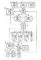
以下、本発明の一実施形態による3次元モデル構築システムを図面を参照して説明する。図1は同実施形態の構成を示すブロック図である。この図において、符号1は、ラインCCDカメラを使用して取得したモデル化対象物体の画像データが格納された画像データファイルである。符号2は、レーザレンジスキャナを使用して取得したモデル化対象物体の測距データを格納した測距データファイルである。符号3は、画像データ及び測距データを取得したときのラインCCDカメラとレーザレンジスキャナの位置及び姿勢のデータを格納した位置姿勢データファイルである。符号4は、位置姿勢データに基づいて、測距データを地球座標系の座標値に変換するとともに、画像データと地球座標系の座標値との関連付けることにより取得したデータを統合するデータ統合部である。符号5は、データ統合部4により得られたモデル化対象物体の測定点群を地球座標系に変換したデータ(ここでは、3次元点群データと称する)を格納する3次元点群データファイルである。符号6は、データ統合部4により画像データファイル1に格納されている画像データを測距データファイル2に格納されている測距データと関連付けるともに、位置姿勢データファイル3に格納されている位置姿勢データに基づいて補正した画像データ(ここでは、統合画像データと称する)が格納する統合画像データファイルである。
【0018】
符号7は、3次元点群データ及び統合画像データを使用して、3次元モデルデータを生成するモデル生成部である。符号8は、生成した3次元モデルデータを格納する3次元モデルデータファイルである。符号9は、キーボードやマウスで構成される入力部である。符号10は、画面表示や画面上の位置指定の処理を行う画面処理部である。符号11は、画像表示が可能なディスプレイである。符号12は、3次元モデルを構成する面オブジェクトを生成する面オブジェクト生成部である。符号13は、3次元モデルを構成する線オブジェクトを生成する線オブジェクト生成部である。符号14は、3次元モデルを構成する点オブジェクトを生成する点オブジェクト生成部である。符号15は、統合画像データに基づいて、データ補完を行うデータ補完部である。符号16は、統合画像データ及び3次元点群データを統合画像データファイル6、3次元点群データファイル5から読み出すデータ読み込み部である。符号17は、目印となる看板等のデータが予め記憶されたロゴデータベースである。符号18は、他の計測手段によって生成された3次元多角形面データが記憶された3次元多角形面データファイルである。
【0019】
次に、画像データファイル1、測距データファイル2及び位置姿勢データファイル3に格納される各データの取得方法について簡単に説明する。データの取得は、3台のレーザレンジスキャナと6台のラインCCDカメラと航法装置(GPS/INS/Odometer)を計測車両のルーフに取り付け、計測車両が走行することにより、沿道の建造物等の計測データを取得することにより行う。ここで使用するレーザレンジスキャナは、シングルスキャン方式であり、計測レートが20Hz(1秒間20回転)、1回転で計測範囲300度の間に距離範囲が70m以内の480個のレーザレンジポイントを計測できる。ラインCCDカメラは、8mm、F4の魚眼レンズを装着し、計測レートは約80Hz(1秒間80ライン)。各ライン画像は180度の間に2048点のRGBピクセルを計測できる。各レーザレンジスキャナとラインCCDカメラの計測面をそれぞれ計測車の進行方向と45、90、135度の垂直面に配置し、計測車両が走行しながら沿道物の断面図を3方向から計測し、また航法装置が出力した位置姿勢と時刻データ、又は各センサ間の相対標定要素によって各地点を計測したレーザレンジデータとラインCCD画像を地球座標系に統合する。図7に3台のレーザレンジスキャナと6台のラインCCDカメラと航法装置(GPS/INS/Odometer)を計測車両のルーフに取り付けた場合の配置図を示す。図1に示す画像データファイル1、測距データファイル2及び位置姿勢データファイル3に格納される各データの取得方法については、特開2002−031528号公報に記載されているデータ取得方法を適用することができるので、詳細な動作等の説明は省略する。
【0020】
次に、画像データファイル1、測距データファイル2及び位置姿勢データファイル3の各ファイルに格納されているデータから3次元点群データファイル5及び統合画像データファイル6を生成する動作を説明する。まず、データ統合部4は、位置姿勢データを参照して、画像データの歪みを補正する。計測車両にラインCCDを搭載して計測した画像データは、車両が走行することにより2次元の画像を取得するものであるが、計測車両のロール、ピッチ、バウンド(上下振動)、さらには、走行速度の変化によって、歪んだ画像データとなってしまう。そこで、各画素データに対して、位置姿勢データに基づく補正を行うことによってこの歪みを補正することが可能となる。続いて、データ統合部4は、位置姿勢データを参照して、3台のレーザレンジスキャナで計測した各測定点の測距データのすべてを1つの地球座標系の座標値に変換して、3次元点群データとする。
【0021】
次に、データ統合部4は、各測距データ(3次元点群データ)を同方向の計測面で撮影した画像データに投影する。例えば、2番のレーザレンジスキャンナが計測して得られた測距データ(3次元点群データ)を2番と5番のラインCCD画像に投影する。そして、各レーザレンジスキャンラインi(1回転のデータ)に対して、2番と5番のラインCCDの画像データから最も一致する計側面で撮影した画像データj2とj5を探す。次に、各レーザレンジスキャンラインiにある各レーザレンジポイントsに対して、j2とj5にある計測方向の最も一致するピクセルtを探し、レーザレンジポイントsをピクセルtに投影すると、測距データと画像データが関連付けられ、その結果を統合画像データファイル6、3次元点群データファイル5へ格納する。
【0022】
このデータ統合処理によって、3次元点群データファイル5には、地球座標系における測定点の座標値が格納され、この測定点と画像データが関連付けられ統合画像データファイル6に格納されることとなる。
なお、3次元点群データファイル5及び統合画像データファイル6の生成方法は、前述した方法に限らず他の方法で生成したデータであってもよい。
また、CCD画像に基づいてその他の計測手段により生成された3次元多角形面データファイル18を補完する場合には、データ統合部4は、3次元多角形面データをCCD画像データに投影する。まず、3次元多角形面データfの中心点pに対して、各ラインCCD画像データから撮影方向の最も一致するピクセルtを探す、ピクセルtに関連付けられた測距データsはピクセルtの撮影中心からpまでの距離dと一致するかどうかを検証する。投影の正当性が検証されたラインCCD画像データから距離dの最も短い且つ平面fへの入射角の最も大きいラインCCD画像データjを3次元多角形面データfと関連付けられる。次に、3次元多角形面データfの各頂点に対して、ラインCCD画像データjから撮影方向の最も一致するピクセルを探し、関連付ける。その結果を統合画像データファイル6へ格納する。
なお、その他の計測手段により生成された3次元多角形面データファイル18と画像データファイル1の統合、また統合画像データファイル6の生成方法は、前述した方法に限らず他の方法で生成したデータであってもよい。
【0023】
ここで、本発明の方法によって生成する3次元モデルについて説明する。本発明によって生成する3次元モデルは、多角形の平面で表現する面オブジェクト、線分で表現する線オブジェクト、特徴点で表現する点オブジェクトの組み合わせで構成されるものであり、面オブジェクトに関しては、画像データをテクスチャとして用いてより現実感を得るものである。
【0024】
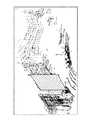
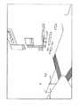
次に、図1に示すモデル生成部7が、3次元点群データファイル5及び統合画像データファイル6に格納されているデータから3次元モデルを生成する動作を説明する。ここでは、動作原理の説明を簡単にするために、図2、図3を例にして説明する。図2は、統合画像データファイル6に格納される画像データの一例を示す図である。図3は、図2に示す計測位置にレーザレンジスキャナを設置して、図2に撮像されている建造物を計測したレーザレンジデータを地球座標系においてプロットし、視点位置が計測位置より高くなるように視点位置を変更する座標変換を施した状態を表示部11に表示した例である。図2の画像データは、建造物の状態を分かり易くするために、実際の画像データに比べて視点位置が高い位置になった状態の画像となっているが、実際には、図2に示す計測位置にラインCCDカメラを設置し、レーザレンジスキャナがスキャンした計測範囲を撮像した画像が統合画像データファイル6には格納されている。
【0025】
次に、各オブジェクトを生成する動作を説明する。まず、オペレータが入力部9から3次元モデル生成の指示を入力すると、モデル生成部7は、データ読み込み部16に対して、画像データと3次元点群データを読み出すように指示する。これを受けて、データ読み込み部16は、図2に示す画像データと図3に示す3次元点群データを読み出し、モデル生成部7へ受け渡す。そして、モデル生成部7は、この受け取ったデータを画面処理部10へ出力する。このとき、画面処理部10は、モデル生成部7より受け取った3次元点群データに対して、任意の視点位置変換を施した後に、表示部11へ出力することによりデータの表示を行う。この操作によって、表示部11には、図2、図3に示す画像が同時に表示されたこととなる。
【0026】
次に、オペレータは、面オブジェクトの生成を入力部9より指定する。これを受けて、モデル生成部7は、多角形の頂点を指定するようにメッセージを表示部11へ表示する。続いて、オペレータは画像データが表示されている画面(図2)上で面オブジェクトの範囲を示す多角形の頂点位置を入力部9のマウスを使用して指定する。ここでは、図4に示す符号A,B,C,Dを順に指定したものとする。画面処理部10は、この画面上の座標値を読み取り、モデル生成部7へ通知する。そして、モデル生成部7は、4つの座標値を面オブジェクト生成部12へ受け渡す。これを受けて、面オブジェクト生成部12は、頂点の座標値で特定される多角形領域内に投影されたレーザレンジポイントを抽出し、空間平面を当てはめる。図5に、頂点の座標値で特定される多角形領域内に投影されたレーザレンジポイントを抽出し、空間平面を当てはめた時の画面表示例を示す。
【0027】
次に、面オブジェクト生成部12は、該当多角形領域内にある画像データのピクセルをその投影方向線に沿って、空間平面に投影し、該当する平面のテクスチャを画像データから切り出す。続いて、該当多角形領域の頂点が対応する画像データのピクセルの投影方向線に沿って、平面へ投影し、空間平面多角形領域の頂点を求め、モデル作成部7へ受け渡す。
【0028】
次に、モデル生成部7は、切り出したテクスチャー画像と既存のロゴデータベース17に記憶されているデータとをマッチングして、ショップ看板や道路交通標識などの種類を見つけ、該当面オブジェクトに属性を付与する。マッチングが失敗した場合、モデル生成部7は、入力部9より入力された属性をこの面オブジェクトに付与する。そして、モデル生成部7は、ここで得られた面オブジェクトを3次元モデルデータファイル8へ書き込む。これにより面オブジェクトが3次元モデルデータファイル8へ書き込まれたことになり、この3次元モデルデータを表示すると図6の符号P1で示す面オブジェクトが表示される。この面オブジェクトは、単に多角形を表示しているだけでなく、画像データをテクスチャとして用いている。
【0029】
なお、都市空間にある平面的なオブジェクトの大半はほぼ垂直かほぼ水平の2種類に分けられるため、特にスケールの小さい、また周囲に歩行者、通行車両、樹木、電柱、電線などのデータが混在している平面の当てはめについては、次のように求めるようにしてもよい。まず、ほぼ垂直な面オブジェクトに対して、抽出されたレーザレンジポイントをあるグリッド化した水平面に投影して、Z−imageと呼ぶ画像を作る。Z−imageにあるピクセルの値は該当するグリッドに投影されたレーザレンジポイント数である。Z−imageにあるラインセグメントは空間上の垂直平面を表す。こうした過程で、垂直方向でポイント数の累積の多い垂直平面を強く強調し、その他のオブジェクトを弱める。次に、Z−imageから最も鮮明且つ長いラインセグメントを抽出すし、ラインセグメントの周囲に投影されたレーザレンジポイントで、最小二乗法によって平面パラメータを求める。また、ほぼ水平な面オブジェクトに対して、抽出されたレーザレンジポイントの標高値によってヒストグラムを作って、最もピークになった標高値を求め、該当標高値を中心にある許容範囲内の標高値を持つレーザレンジポイントを抽出して、最小二乗法によって平面パラメータを求める。
なお、ここでは、面として平面のみを対象として説明したが、同様の処理を適用することにより、円柱や球等の曲面のオブジェクトを生成するようにしてもよい。
【0030】
次に、オペレータは、線オブジェクトの生成を入力部9より指定する。これを受けて、モデル生成部7は、線オブジェクトの屈曲点または端点を指定するようにメッセージを表示部11へ表示する。続いて、オペレータは画像データが表示されている画面(図2)上で線オブジェクトの屈曲点または端点位置を入力部9のマウスを使用して指定する。ここでは、図4の符号J、Kの位置(外灯)が指定されたものとする。これを受けて、画面処理部10は、この画面上の座標値を読み取り、モデル生成部7へ通知する。そして、モデル生成部7は、指定された座標値を線オブジェクト生成部13へ受け渡す。これを受けて、線オブジェクト生成部13は、屈曲点または端点が対応する画像データのピクセルの周囲の所定許容範囲内に投影されたレーザレンジポイント(3次元点群データ)の中心点を取り、空間上の線オブジェクトの屈曲点または端点とする。ただし、こうした過程では、歩行者、通行車両、樹木、データ統合時に生じた誤差、また太陽直射などによる計測誤差により、間違ったポイントを抽出する可能性がある。そこで、次のような補助手順によって、雑多なデータが混在している環境でも確実にポイント抽出を行う。
【0031】
線オブジェクト生成部13は、指定された複数の線分の周囲に、所定許容範囲内に投影されたレーザレンジポイント(3次元点群データ)を抽出し、最小二乗法によって空間平面を求め、投影面とする。そして、得られた投影面をグリッド(格子)化し、抽出されたレーザレンジポイント(3次元点群データ)を投影面に投影して、hybrid Z−imageと呼ぶ画像を生成する。そこで、hybrid Z−imageにあるピクセルの値は対応するグリッドに投影されたレーザレンジポイント(3次元点群データ)の数である。こうした過程によって3次元空間にある複数の線分の形状が最大限で2次元画像に表現することができる。続いて、先に求めた屈曲点または端点をhybrid Z−imageに投影して、レーザレンジポイント(3次元点群データ)で表す線分の形状と一致するかどうかを確認する。そして、一致しない場合、オペレータはhybridZ−image上で投影されたポリラインを修正する。修正された線分の屈曲点または端点に対して、対応するhybrid Z−imageに投影されたレーザレンジポイント(3次元点群データ)の中心点を求めて、空間上の屈曲点または端点とする。この屈曲点または端点で特定される複数の線分が線オブジェクトである。
【0032】
次に、線オブジェクト生成部13は、この線オブジェクトのデータをモデル生成部7へ受け渡す。続いて、モデル生成部7は、この線オブジェクトとロゴデータベース7に記憶されているデータとマッチングして、路上灯や歩道界などを種類分けして、該当線オブジェクトに属性を付与する。また、マッチングが失敗した際には、入力部9より入力した属性を付与する。そして、モデル生成部7は、ここで得られた線オブジェクトを3次元モデルデータファイル8へ書き込む。これにより線オブジェクトが3次元モデルデータファイル8へ書き込まれたことになり、この3次元モデルデータを表示すると図6の符号L1で示す線オブジェクトが表示される。また、同様に、図4において、符号G、H、Iと符号E、Fと指定した場合には、それぞれ図6の符号L2、L3で示す線オブジェクトが生成されることになる。
なお、ここでは、直線を例にして説明したが、短い線オブジェクトの集まりによって、円弧等の曲線のオブジェクトを生成するようにしてもよい。
【0033】
次に、オペレータは、点オブジェクトの生成を入力部9より指定する。これを受けて、モデル生成部7は、特徴点の位置を指定するようにメッセージを表示部11へ表示する。続いて、オペレータは画像データが表示されている画面(図2)上で特徴点の位置を入力部9のマウスを使用して指定する。これを受けて、画面処理部10は、この画面上の座標値を読み取り、モデル生成部7へ通知する。そして、モデル生成部7は、指定された座標値を点オブジェクト生成部14へ受け渡す。これを受けて、点オブジェクト生成部13は、この座標値が対応する画像データのピクセルの周囲に、所定許容範囲内に投影されたレーザレンジポイントの中心点を取って、点オブジェクトの空間座標値とする。点オブジェクト生成部14は、この座標値をモデル生成部7へ受け渡す。これを受けて、モデル生成部7は、この空間座標値を3次元モデルデータファイル8へ書き込む。
【0034】
次に、その他の計測手段による生成された3次元多角形面データファイル18に記憶されている3次元多角形面データの補完を行う動作を説明する。測距データの計測エラーや既存の3次元モデルデータ製作手段の制限などによって、その他の計測手段により生成された3次元多角形面データファイル18に記憶されている3次元多角形面データには誤差が含まれていることがあり、テクスチャデータがなく現実感を欠くことがあるため、ラインCCD画像データに基づいて補完する。まず、入力部9よりデータの補完の指示を受けると、モデル生成部7は、データ補完部15に対して、データ補完の指示を出す。これを受けて、データ補完部15は、その他の計測手段により生成された3次元モデルデータを画像データ上に投影して、それによって描いたオブジェクト形状が画像データ上に撮影されたものと一致するか否かを確認する。
【0035】
次に、オペレータは画像データ上に投影された一致しない多角形の頂点に対して、正しい投影場所を画面上においてマウスで指定する。そして、対応する画像データのピクセルの撮影方向線と該当する頂点が属する多角形の空間平面との交点を求めることによって、頂点に対して新しい空間座標値を与える。続いて、投影された多角形に囲まれた画像データのピクセルを撮影方向線に沿って、該当多角形の空間平面に投影し、リサンプリングによって該当多角形のテクスチャー画像を生成する。
このようにして、その他の計測手段により生成された3次元多角形面データファイル18に記憶されている3次元多角形面データの誤差が大きい場合においても画像データに基づいて補完することが可能となる。また、テクスチャーデータの生成によってより現実感を得ることも可能となる。
【0036】
以上の動作を繰り返すことによって、面、線、点からなるオブジェクトの集合として、3次元モデルデータが生成されることとなる。図8、図9に、実際に市街地を計測車両で走行し、取得したデータに基づいて3次元モデルデータを生成し、画面表示した例を示す。本発明によれば、図8に示すように、建造物の表面は、CCD画像をそのままテクスチャとして用いたため、現実感のある3次元モデルデータを作成することができる。また、平面、線等のオブジェクトを3次元点群データに基づいて位置関係を求めるようにしたため、正確な3次元モデルデータとすることが可能となる。また、図9に示すように、市街地内の目印となる看板などもCCD画像をそのまま用いることが可能となり、標識や信号さらには横断歩道等もリアルに表現することができるため、自動車に用いるナビゲーションシステムの表示データとして最適なデータを生成することが実現できる。
【0037】
従来は、レーザスキャナなどによる距離画像や、CCDカメラなどによる多重立体視画像などを用いてさまざまな対象物の3次元計測を行い、3次元モデルを自動構築する開発事例は数多いが、対象物の形状や構造が複雑な場合、完全な自動構築はきわめて困難であり、結局手作業が多くなり、結局自動化システムを導入してもそれほどの省力化効果が得られないことが多かった。
【0038】
しかし、本発明では、3次元点群データとCCD画像を重ね合わせたものを用意し、人間にとって判読しやすいCCD画像上で対象物の輪郭線をなぞるだけで、その対象物の3次元モデルを構築することを可能とし、手作業の大幅な効率向上を図ることができる。特に入力された輪郭線に対応する3次元点群データを切り出し、そこに面(サーフェス)や線分、点などを適宜あてはめることで、3次元モデルを構築するようにしたため、たとえば屋外画像に現れる建物や道路だけではなく、店舗の看板、信号機、道路交通標識、信号、歩道、ベンチなど、複雑な形状を含む幅広い3次元空間モデルを極めて効率的に構築することができる。これは、コンピュータグラフィックスや数値地図、測量、CADなど実在する対象物の3次元モデルを計測したり、さらにはナビゲーションシステム用の表示データの作成に利用可能である。
【0039】
なお、図1における各処理部の機能を実現するためのプログラムをコンピュータ読み取り可能な記録媒体に記録して、この記録媒体に記録されたプログラムをコンピュータシステムに読み込ませ、実行することにより3次元モデルデータ生成処理を行ってもよい。なお、ここでいう「コンピュータシステム」とは、OSや周辺機器等のハードウェアを含むものとする。また、「コンピュータシステム」は、ホームページ提供環境(あるいは表示環境)を備えたWWWシステムも含むものとする。また、「コンピュータ読み取り可能な記録媒体」とは、フレキシブルディスク、光磁気ディスク、ROM、CD−ROM等の可搬媒体、コンピュータシステムに内蔵されるハードディスク等の記憶装置のことをいう。さらに「コンピュータ読み取り可能な記録媒体」とは、インターネット等のネットワークや電話回線等の通信回線を介してプログラムが送信された場合のサーバやクライアントとなるコンピュータシステム内部の揮発性メモリ(RAM)のように、一定時間プログラムを保持しているものも含むものとする。
【0040】
また、上記プログラムは、このプログラムを記憶装置等に格納したコンピュータシステムから、伝送媒体を介して、あるいは、伝送媒体中の伝送波により他のコンピュータシステムに伝送されてもよい。ここで、プログラムを伝送する「伝送媒体」は、インターネット等のネットワーク(通信網)や電話回線等の通信回線(通信線)のように情報を伝送する機能を有する媒体のことをいう。また、上記プログラムは、前述した機能の一部を実現するためのものであっても良い。さらに、前述した機能をコンピュータシステムにすでに記録されているプログラムとの組み合わせで実現できるもの、いわゆる差分ファイル(差分プログラム)であっても良い。
【0041】
【発明の効果】
以上説明したように、本発明によれば、高精度3次元情報を持つレーザレンジデータから変換して得られた3次元点群データを、テクスチャー情報を持つ画像データに投影し、画像データの画面を作業画面として計測対象物の領域を手動で入力し、該当領域に統合された3次元点群データによって対象物の3次元形状を求めことによって、建物や道路だけではなく、ショップ看板、信号機、道路交通標識、歩道など幅広い3次元空間データを効率的にかつ容易に生成することができるという効果が得られる。
【図面の簡単な説明】
【図1】 本発明の一実施形態の構成を示すブロック図である。
【図2】 図1に示す装置の動作を説明するための表示画面例を示す説明図である。
【図3】 図1に示す装置の動作を説明するための表示画面例を示す説明図である。
【図4】 図1に示す装置の動作を説明するための表示画面例を示す説明図である。
【図5】 図1に示す装置の動作を説明するための表示画面例を示す説明図である。
【図6】 図1に示す装置の動作を説明するための表示画面例を示す説明図である。
【図7】 3台のレーザレンジスキャナと6台のラインCCDカメラと航法装置を計測車両のルーフに取り付けた場合の配置図である。
【図8】 生成した3次元モデルデータの一例を示す説明図である。
【図9】 生成した3次元モデルデータの一例を示す説明図である。
【符号の説明】
1・・・画像データファイル
2・・・測距データファイル
3・・・位置姿勢データファイル
4・・・データ統合部
5・・・3次元点群データファイル
6・・・統合画像データファイル
7・・・モデル生成部
8・・・3次元モデルデータファイル
9・・・入力部
10・・・画面処理部
11・・・表示部
12・・・面オブジェクト生成部
13・・・線オブジェクト生成部
14・・・点オブジェクト生成部
15・・・データ補完部
16・・・データ読み込み部
17・・・ロゴデータベース
18・・・3次元多角形面データファイル[0001]
BACKGROUND OF THE INVENTION
The present invention relates to a three-dimensional model construction system and a three-dimensional model construction program for constructing a three-dimensional model of an object from three-dimensional point cloud data and image data acquired by a laser scanner or the like.
[0002]
[Prior art]
The real world consists of diverse and complex objects, as represented by urban spaces composed of buildings, roads, signs, and various facilities. There are many fields in which such objects are measured and used as a three-dimensional model, including computer graphics. However, since the cost that can be input to a three-dimensional model is limited in many fields, a method for efficiently measuring and modeling a three-dimensional shape is indispensable. Speaking of cities, there have been many practical methods for acquiring 3D data of cities from the sky by using techniques such as aerial photogrammetry. This is an excellent method for efficiently covering a wide area. However, the use of 3D space data in the future is expected to increase the number of cases that require detailed 3D representation from the viewpoint of pedestrians and drivers on the ground. Therefore, it is necessary to more accurately model complex objects that serve as landmarks such as traffic lights.
[0003]
On the other hand, systems that acquire three-dimensional information from the ground using techniques such as stereo photography and moving images and extract signboards and signs, utility poles, and white lines of roads as landmarks have been developed (eg, patent documents). 1, 2). In recent years, the price of laser range scanners using eye-safe lasers has been reduced and is being applied to three-dimensional measurement systems in urban areas, large indoor environments, and ruins. Since the laser range scanner can acquire the shape of an object as point cloud data (three-dimensional point cloud data) directly and with high accuracy, the laser range scanner can be used to obtain a relatively large scale and simple shape. It is applied to object modeling (for example, Patent Document 3).
[0004]
[Patent Document 1]
JP 2002-081941 A
[Patent Document 2]
JP 09-319896 A
[Patent Document 3]
JP 2003-021507 A
[0005]
[Problems to be solved by the invention]
However, since modeling using point cloud data has limited spatial resolution, it is not always easy to automate the process of generating a surface from a point cloud and building a three-dimensional model. Furthermore, it is very difficult to automatically read the object from the image and the point cloud data. For this reason, model creation technology with full automation in mind is very effective for targets that can be easily automated, but in most cases, both simple and complex are mixed. There is a problem that the scope of application is limited to a small part. As a result, many remaining objects and objects for which automation has failed must be modeled manually, and in most cases, the efficiency improvement effect due to automation can hardly be exhibited. For this reason, there is a demand for a method that makes use of human's superior ability to identify and classify objects while simplifying and improving human work.
[0006]
The present invention has been made in view of such circumstances, and a three-dimensional model construction system and a three-dimensional model construction program capable of easily constructing a three-dimensional model of an object from three-dimensional point cloud data and image data. The purpose is to provide.
[0007]
[Means for Solving the Problems]
Book The present invention relates to a three-dimensional model construction system in which image data and three-dimensional point cloud data are stored in association with each other, and a three-dimensional model is constructed from these data. A data file for storing three-dimensional model data Display means for displaying the image data and the three-dimensional point cloud data on a screen, designation means for designating a polygonal area on the screen on which the image data is displayed, and 3 included in the polygonal area. Extraction means for extracting three-dimensional point cloud data, and a plane object that specifies a plane object by obtaining a three-dimensional coordinate value of the polygonal area based on the extracted three-dimensional point cloud data and writes it to the data file And generating means.
[0008]
Book The present invention provides the 3D model construction system, wherein the line segment 3D is based on means for designating an end point or bending point of the line segment on the screen on which the image data is displayed, and the 3D point cloud data. A line object generating means for specifying a line object by obtaining coordinate values and writing to the data file;
Is further provided.
[0009]
Book According to the invention, the 3D model construction system obtains a 3D coordinate value of the feature point based on the means for designating the feature point on the screen on which the image data is displayed and the 3D point cloud data. And a point object generating means for specifying the point object and writing it to the data file.
[0010]
Book The invention is characterized in that the plane object generation means extracts image data in the polygonal region and writes the image data as a texture to the data file.
[0011]
Book The invention is characterized in that the three-dimensional model construction system further comprises data complementing means for complementing three-dimensional polygonal plane data generated by other measuring means based on the image data.
[0012]
Book The invention relates to a three-dimensional model construction program in which image data and three-dimensional point cloud data are associated and stored, a three-dimensional model is constructed from these data, and the obtained three-dimensional model data is written in a data file. A display process for displaying the image data and the three-dimensional point cloud data on a screen, a designation process for designating a polygonal area on the screen on which the image data is displayed, and a polygonal area. A plane object is identified by obtaining a three-dimensional coordinate value of the polygonal area based on the extracted three-dimensional point cloud data and the extracted three-dimensional point cloud data, and written to the data file A plane object generation process is performed by a computer.
[0013]
Book In the invention, the 3D model construction program is configured to specify the end point or the bending point of the line segment on the screen on which the image data is displayed, and the 3D line segment based on the 3D point cloud data. A line object is identified by obtaining a coordinate value, and a line object generating process for writing to the data file is further performed by a computer.
[0014]
Book The invention is such that the 3D model construction program obtains a 3D coordinate value of the feature point based on the process of designating the feature point on the screen on which the image data is displayed and the 3D point cloud data. A point object is specified by the above, and a point object generation process for writing to the data file is further performed by the computer.
[0015]
Book The invention is characterized in that the plane object generation processing extracts image data in the polygonal region and writes the image data as a texture to the data file.
[0016]
Book The invention is characterized in that the three-dimensional model construction program further causes the computer to perform a data complementing process for complementing the three-dimensional polygonal plane data generated by other measuring means based on the image data.
[0017]
DETAILED DESCRIPTION OF THE INVENTION
Hereinafter, a three-dimensional model construction system according to an embodiment of the present invention will be described with reference to the drawings. FIG. 1 is a block diagram showing the configuration of the embodiment. In this figure,
[0018]
Reference numeral 7 denotes a model generation unit that generates 3D model data using the 3D point cloud data and the integrated image data. Reference numeral 8 denotes a three-dimensional model data file that stores the generated three-dimensional model data.
[0019]
Next, a method of acquiring each data stored in the
[0020]
Next, an operation for generating the three-dimensional point cloud data file 5 and the integrated image data file 6 from the data stored in the
[0021]
Next, the
[0022]
By this data integration processing, the coordinate values of the measurement points in the earth coordinate system are stored in the three-dimensional point cloud data file 5, and the measurement points and the image data are associated and stored in the integrated image data file 6. .
The generation method of the three-dimensional point cloud data file 5 and the integrated image data file 6 is not limited to the method described above, and may be data generated by another method.
When complementing the three-dimensional polygonal plane data file 18 generated by other measuring means based on the CCD image, the
Note that the method for integrating the three-dimensional polygonal plane data file 18 and the image data file 1 generated by other measuring means and the method for generating the integrated image data file 6 is not limited to the above-described method, and data generated by other methods. It may be.
[0023]
Here, the three-dimensional model generated by the method of the present invention will be described. The three-dimensional model generated by the present invention is composed of a combination of a plane object expressed by a polygonal plane, a line object expressed by a line segment, and a point object expressed by a feature point. The image data is used as a texture to obtain a more realistic feeling.
[0024]
Next, an operation in which the model generation unit 7 shown in FIG. 1 generates a three-dimensional model from data stored in the three-dimensional point cloud data file 5 and the integrated image data file 6 will be described. Here, in order to simplify the explanation of the operation principle, description will be made with reference to FIGS. FIG. 2 is a diagram illustrating an example of image data stored in the integrated
[0025]
Next, an operation for generating each object will be described. First, when the operator inputs an instruction for generating a three-dimensional model from the
[0026]
Next, the operator designates generation of a plane object from the
[0027]
Next, the plane
[0028]
Next, the model generation unit 7 matches the clipped texture image with the data stored in the existing
[0029]
Most of the planar objects in the urban space are divided into two types, almost vertical and almost horizontal, so the data of pedestrians, passing vehicles, trees, utility poles, electric wires, etc. are especially small in the surroundings. You may make it obtain | require as follows about the fitting of the plane which is doing. First, an extracted laser range point is projected onto a grid-like horizontal plane with respect to a substantially vertical plane object, thereby creating an image called Z-image. The value of the pixel in Z-image is the number of laser range points projected on the corresponding grid. The line segment in Z-image represents a vertical plane in space. In this process, the vertical plane with many accumulated points in the vertical direction is strongly emphasized, and other objects are weakened. Next, the sharpest and longest line segment is extracted from the Z-image, and the plane parameter is obtained by the least square method at the laser range points projected around the line segment. In addition, for a nearly horizontal surface object, a histogram is created from the extracted laser range point elevation values to obtain the highest peak elevation value, and the elevation value within the allowable range centered on the relevant elevation value. The laser range point is extracted and the plane parameter is obtained by the least square method.
Note that although only a plane has been described as a target here, a curved object such as a cylinder or a sphere may be generated by applying the same processing.
[0030]
Next, the operator designates generation of a line object from the
[0031]
The line
[0032]
Next, the line
Although a straight line has been described here as an example, a curved object such as an arc may be generated by a collection of short line objects.
[0033]
Next, the operator designates generation of a point object from the
[0034]
Next, an operation for complementing the 3D polygon surface data stored in the 3D polygon surface data file 18 generated by the other measuring means will be described. 3D polygon surface data stored in the 3D polygon surface data file 18 generated by other measurement means due to measurement errors of distance measurement data or limitations of existing 3D model data production means, etc. Is included, and there is no texture data, and the sense of reality may be lacking. Therefore, the interpolation is performed based on the line CCD image data. First, upon receiving a data complement instruction from the
[0035]
Next, the operator designates the correct projection location on the screen with the mouse for the non-matching polygonal vertexes projected on the image data. Then, a new spatial coordinate value is given to the vertex by obtaining the intersection of the shooting direction line of the pixel of the corresponding image data and the polygonal spatial plane to which the corresponding vertex belongs. Subsequently, the pixel of the image data surrounded by the projected polygon is projected onto the space plane of the corresponding polygon along the shooting direction line, and the texture image of the corresponding polygon is generated by resampling.
In this way, even when the error of the three-dimensional polygonal plane data stored in the three-dimensional polygonal plane data file 18 generated by other measuring means is large, it is possible to complement based on the image data. Become. It is also possible to obtain a more realistic feeling by generating texture data.
[0036]
By repeating the above operation, three-dimensional model data is generated as a collection of objects composed of surfaces, lines, and points. FIG. 8 and FIG. 9 show examples in which a three-dimensional model data is generated based on the acquired data, actually traveled in a city area with a measurement vehicle, and displayed on the screen. According to the present invention, as shown in FIG. 8, since the CCD image is used as it is as the texture on the surface of the building, realistic three-dimensional model data can be created. In addition, since the positional relationship is obtained for objects such as planes and lines based on the three-dimensional point cloud data, accurate three-dimensional model data can be obtained. Further, as shown in FIG. 9, a CCD image can be used as it is for a signboard or the like in a city area, and a sign, a signal, a pedestrian crossing, or the like can be realistically expressed. It is possible to generate optimal data as display data of the system.
[0037]
Conventionally, there are many development examples in which a three-dimensional model is automatically constructed by performing three-dimensional measurement of various objects using a distance image obtained by a laser scanner or the like and a multi-stereoscopic image obtained by a CCD camera or the like. When the shape and structure are complex, complete automatic construction is extremely difficult, and as a result, there are many manual operations. After all, even if an automation system is introduced, the labor saving effect is often not obtained.
[0038]
However, in the present invention, a superimposition of 3D point cloud data and a CCD image is prepared, and a 3D model of the object can be obtained by simply tracing the outline of the object on a CCD image that is easy for humans to read. It is possible to construct it, and the efficiency of manual work can be greatly improved. In particular, 3D point cloud data corresponding to the input contour line is cut out, and a 3D model is constructed by appropriately assigning surfaces (surfaces), line segments, points, etc. thereto, so that it appears in an outdoor image, for example. In addition to buildings and roads, a wide range of three-dimensional space models including complex shapes such as store signs, traffic lights, road traffic signs, signals, sidewalks, and benches can be constructed very efficiently. This can be used to measure a three-dimensional model of an actual object such as computer graphics, a numerical map, surveying, or CAD, or to create display data for a navigation system.
[0039]
A three-dimensional model is obtained by recording a program for realizing the functions of the processing units in FIG. 1 on a computer-readable recording medium, causing the computer system to read and execute the program recorded on the recording medium. Data generation processing may be performed. Here, the “computer system” includes an OS and hardware such as peripheral devices. The “computer system” includes a WWW system having a homepage providing environment (or display environment). The “computer-readable recording medium” refers to a portable medium such as a flexible disk, a magneto-optical disk, a ROM, and a CD-ROM, and a storage device such as a hard disk built in the computer system. Further, the “computer-readable recording medium” refers to a volatile memory (RAM) in a computer system that becomes a server or a client when a program is transmitted via a network such as the Internet or a communication line such as a telephone line. In addition, those holding programs for a certain period of time are also included.
[0040]
The program may be transmitted from a computer system storing the program in a storage device or the like to another computer system via a transmission medium or by a transmission wave in the transmission medium. Here, the “transmission medium” for transmitting the program refers to a medium having a function of transmitting information, such as a network (communication network) such as the Internet or a communication line (communication line) such as a telephone line. The program may be for realizing a part of the functions described above. Furthermore, what can implement | achieve the function mentioned above in combination with the program already recorded on the computer system, and what is called a difference file (difference program) may be sufficient.
[0041]
【The invention's effect】
As described above, according to the present invention, three-dimensional point cloud data obtained by conversion from laser range data having high-precision three-dimensional information is projected onto image data having texture information, and the image data screen is displayed. As a work screen, manually input the area of the measurement object, and obtain the 3D shape of the object from the 3D point cloud data integrated in the area, so that not only buildings and roads, but also shop signs, traffic lights, There is an effect that a wide range of three-dimensional spatial data such as road traffic signs and sidewalks can be generated efficiently and easily.
[Brief description of the drawings]
FIG. 1 is a block diagram showing a configuration of an embodiment of the present invention.
FIG. 2 is an explanatory view showing an example of a display screen for explaining the operation of the apparatus shown in FIG. 1;
3 is an explanatory diagram showing an example of a display screen for explaining the operation of the apparatus shown in FIG. 1; FIG.
4 is an explanatory view showing an example of a display screen for explaining the operation of the apparatus shown in FIG. 1; FIG.
FIG. 5 is an explanatory diagram showing an example of a display screen for explaining the operation of the apparatus shown in FIG. 1;
6 is an explanatory view showing an example of a display screen for explaining the operation of the apparatus shown in FIG. 1; FIG.
FIG. 7 is a layout view when three laser range scanners, six line CCD cameras, and a navigation device are attached to the roof of a measurement vehicle.
FIG. 8 is an explanatory diagram showing an example of generated three-dimensional model data.
FIG. 9 is an explanatory diagram showing an example of generated three-dimensional model data.
[Explanation of symbols]
1 ... Image data file
2 ... Ranging data file
3 ... Position and orientation data file
4. Data integration part
5 ... 3D point cloud data file
6 ... Integrated image data file
7 ... Model generator
8 ... 3D model data file
9 ... Input section
10 ... Screen processing unit
11 ... Display section
12 ... Plane object generator
13: Line object generator
14: Point object generator
15 ... Data complement part
16 ... Data reading part
17 ... Logo database
18 ... 3D polygon data file
Claims (8)
Translated fromJapanese3次元モデルデータを記憶するデータファイルと、
前記画像データ及び3次元点群データを画面に表示する表示手段と、
前記画像データが表示された画面上において多角形の領域を指定する指定手段と、
前記多角形領域内に含まれる3次元点群データを抽出する抽出手段と、
抽出した前記3次元点群データに基づいて、前記多角形領域の3次元座標値を求めることにより面オブジェクトを特定して、前記データファイルへ書き込む面オブジェクト生成手段と、
前記画像データが表示された画面上において生成するべき線分の端点または屈曲点の位置を指定する線分位置指定手段と、
前記指定された端点または屈曲点の位置の前記画面上の座標値を求め、該座標値の周囲の所定許容範囲内に投影された前記3次元点群データ中の点データのうち、前記所定許容範囲内の中心の点データを選択することにより前記端点または屈曲点の3次元座標値を求めて線オブジェクトを特定して、前記データファイルへ書き込む線オブジェクト生成手段と
を備えたことを特徴とする3次元モデル構築システム。Image data and 3D point cloud data are stored in association with each other, and a 3D model construction system for constructing a 3D model from these data,
A data file for storing 3D model data;
Display means for displaying the image data and the three-dimensional point cloud data on a screen;
Designating means for designating a polygonal area on the screen on which the image data is displayed;
Extracting means for extracting three-dimensional point cloud data included in the polygonal area;
Based on the extracted three-dimensional point cloud data, a plane object generating means for specifying a plane object by obtaining a three-dimensional coordinate value of the polygonal area and writing to the data file;
Line segment position specifying means for specifying the position of the end point or bending point of the line segment to be generated on the screen on which the image data is displayed;
A coordinate value on the screen of the position of the designated end point or bending point is obtained, and among the point data in the three-dimensional point group data projected within a predetermined allowable range around the coordinate value, the predetermined allowable value A line object generating unit that selects a point data of a center within a range to obtain a three-dimensional coordinate value of the end point or the bending point, specifies a line object, and writes the line object to the data file ; 3D model construction system.
前記画像データが表示された画面上において生成するべき特徴点の位置を指定する特徴点位置指定手段と、
前記指定された特徴点の位置の前記画面上の座標値を求め、該座標値の周囲の所定許容範囲内に投影された前記3次元点群データ中の点データのうち、前記所定許容範囲内の中心の点データを選択することにより前記特徴点の3次元座標値を求めて点オブジェクトを特定して、前記データファイルへ書き込む点オブジェクト生成手段と
をさらに備えたことを特徴とする請求項1に記載の3次元モデル構築システム。The three-dimensional model construction system
Feature point position specifying means for specifyingthe position of the feature pointto be generated on the screen on which the image data is displayed;
A coordinate value on the screen of the position of the designated feature point is obtained, and the point data in the three-dimensional point group data projected within the predetermined allowable range around the coordinate value is within the predetermined allowable range. claim to identify a pointobject by selecting the point data of the center of the determined three-dimensional coordinate values of the feature points, characterized by comprising further a object generation means that write to the data file1 3D modeling systemdescribed.
前記画像データに基づいて、他の計測手段により生成された3次元多角形面データを補完するデータ補完手段をさらに備えたことを特徴とする請求項1ないし3のいずれかに記載の3次元モデル構築システム。The three-dimensional model construction system
The three-dimensional model according to any one of claims 1 to3 , further comprising data complementing means for complementing three-dimensional polygonal plane data generated by other measuring means based on the image data. Construction system.
前記画像データ及び3次元点群データを画面に表示する表示処理と、
前記画像データが表示された画面上において多角形の領域を指定する指定処理と、
前記多角形領域内に含まれる3次元点群データを抽出する抽出処理と、
抽出した前記3次元点群データに基づいて、前記多角形領域の3次元座標値を求めることにより面オブジェクトを特定して、前記データファイルへ書き込む面オブジェクト生成処理と、
前記画像データが表示された画面上において生成するべき線分の端点または屈曲点の位置を指定する線分位置指定処理と、
前記指定された端点または屈曲点の位置の前記画面上の座標値を求め、該座標値の周囲の所定許容範囲内に投影された前記3次元点群データ中の点データのうち、前記所定許容範囲内の中心の点データを選択することにより前記端点または屈曲点の3次元座標値を求めて線オブジェクトを特定して、前記データファイルへ書き込む線オブジェクト生成処理と
をコンピュータに行わせることを特徴とする3次元モデル構築プログラム。A three-dimensional model construction program that stores image data and three-dimensional point cloud data in association with each other, constructs a three-dimensional model from these data, and writes the obtained three-dimensional model data to a data file. ,
Display processing for displaying the image data and the three-dimensional point cloud data on a screen;
A designation process for designating a polygonal area on the screen on which the image data is displayed;
Extraction processing for extracting three-dimensional point cloud data included in the polygonal area;
Based on the extracted three-dimensional point cloud data, a plane object is generated by specifying a plane object by obtaining a three-dimensional coordinate value of the polygonal area, and writing to the data file;
A line segment position designation process for designating the position of the end point or bending point of the line segment to be generated on the screen on which the image data is displayed;
A coordinate value on the screen of the position of the designated end point or bending point is obtained, and among the point data in the three-dimensional point group data projected within a predetermined allowable range around the coordinate value, the predetermined allowable value By selecting point data of the center within the range, a three-dimensional coordinate value of the end point or inflection point is obtained, a line object is specified, and a line object generation process to be written to the data file is performed by a computer. A three-dimensional model construction program.
前記画像データが表示された画面上において生成するべき特徴点の位置を指定する特徴点位置指定処理と、
前記指定された特徴点の位置の前記画面上の座標値を求め、該座標値の周囲の所定許容範囲内に投影された前記3次元点群データ中の点データのうち、前記所定許容範囲内の中心の点データを選択することにより前記特徴点の3次元座標値を求めて点オブジェクトを特定して、前記データファイルへ書き込む点オブジェクト生成処理と
をさらにコンピュータに行わせることを特徴とする請求項5に記載の3次元モデル構築プログラム。The three-dimensional model construction program is
Afeature point position specifying process for specifying aposition of afeature pointto be generated on the screen on which the image data is displayed;
A coordinate value on the screen of the position of the designated feature point is obtained, and the point data in the three-dimensional point group data projected within the predetermined allowable range around the coordinate value is within the predetermined allowable range. A point object generating process for obtaininga three-dimensional coordinate value of the feature point by selecting the point data of the feature point, specifyinga point object, and writing to the data file is further performed by the computer. Item 6. The three-dimensional model construction program according to item5 .
前記画像データに基づいて、他の計測手段により生成された3次元多角形面データを補完するデータ補完処理をさらにコンピュータに行わせることを特徴とする請求項5ないし7のいずれかに記載の3次元モデル構築プログラム。The three-dimensional model construction program is
Based on the image data, 3 according to any5 to claim, characterized in that to perform the further computer data interpolation processing to complement the three-dimensional polygonal surface data generated7 of the other measuring means Dimensional model building program.
Priority Applications (1)
| Application Number | Priority Date | Filing Date | Title |
|---|---|---|---|
| JP2003146531AJP4284644B2 (en) | 2003-05-23 | 2003-05-23 | 3D model construction system and 3D model construction program |
Applications Claiming Priority (1)
| Application Number | Priority Date | Filing Date | Title |
|---|---|---|---|
| JP2003146531AJP4284644B2 (en) | 2003-05-23 | 2003-05-23 | 3D model construction system and 3D model construction program |
Publications (2)
| Publication Number | Publication Date |
|---|---|
| JP2004348575A JP2004348575A (en) | 2004-12-09 |
| JP4284644B2true JP4284644B2 (en) | 2009-06-24 |
Family
ID=33533357
Family Applications (1)
| Application Number | Title | Priority Date | Filing Date |
|---|---|---|---|
| JP2003146531AExpired - Fee RelatedJP4284644B2 (en) | 2003-05-23 | 2003-05-23 | 3D model construction system and 3D model construction program |
Country Status (1)
| Country | Link |
|---|---|
| JP (1) | JP4284644B2 (en) |
Families Citing this family (73)
| Publication number | Priority date | Publication date | Assignee | Title |
|---|---|---|---|---|
| DE102006031580A1 (en) | 2006-07-03 | 2008-01-17 | Faro Technologies, Inc., Lake Mary | Method and device for the three-dimensional detection of a spatial area |
| USRE46672E1 (en) | 2006-07-13 | 2018-01-16 | Velodyne Lidar, Inc. | High definition LiDAR system |
| EP2082188B1 (en)* | 2006-10-20 | 2013-06-05 | TomTom Global Content B.V. | Computer arrangement for and method of matching location data of different sources |
| CN101617197B (en)* | 2007-02-16 | 2011-06-22 | 三菱电机株式会社 | Measuring device, measuring method and ground feature recognition device |
| JP5538667B2 (en)* | 2007-04-26 | 2014-07-02 | キヤノン株式会社 | Position / orientation measuring apparatus and control method thereof |
| JP5116555B2 (en)* | 2008-04-25 | 2013-01-09 | 三菱電機株式会社 | LOCATION DEVICE, LOCATION SYSTEM, LOCATION SERVER DEVICE, AND LOCATION METHOD |
| JP4978615B2 (en)* | 2008-11-27 | 2012-07-18 | 三菱電機株式会社 | Target identification device |
| DE102009010465B3 (en) | 2009-02-13 | 2010-05-27 | Faro Technologies, Inc., Lake Mary | laser scanner |
| JP5339953B2 (en)* | 2009-02-17 | 2013-11-13 | 三菱電機株式会社 | 3D map correction apparatus and 3D map correction program |
| DE102009015921A1 (en)* | 2009-03-25 | 2010-09-30 | Faro Technologies, Inc., Lake Mary | Method for optically scanning and measuring an environment |
| DE102009015920B4 (en) | 2009-03-25 | 2014-11-20 | Faro Technologies, Inc. | Device for optically scanning and measuring an environment |
| US9551575B2 (en) | 2009-03-25 | 2017-01-24 | Faro Technologies, Inc. | Laser scanner having a multi-color light source and real-time color receiver |
| JP5464915B2 (en)* | 2009-06-09 | 2014-04-09 | 三菱電機株式会社 | Object detection apparatus and object detection method |
| DE102009035337A1 (en) | 2009-07-22 | 2011-01-27 | Faro Technologies, Inc., Lake Mary | Method for optically scanning and measuring an object |
| DE102009055988B3 (en) | 2009-11-20 | 2011-03-17 | Faro Technologies, Inc., Lake Mary | Device, particularly laser scanner, for optical scanning and measuring surrounding area, has light transmitter that transmits transmission light ray by rotor mirror |
| US9529083B2 (en) | 2009-11-20 | 2016-12-27 | Faro Technologies, Inc. | Three-dimensional scanner with enhanced spectroscopic energy detector |
| DE102009055989B4 (en) | 2009-11-20 | 2017-02-16 | Faro Technologies, Inc. | Device for optically scanning and measuring an environment |
| DE102009057101A1 (en) | 2009-11-20 | 2011-05-26 | Faro Technologies, Inc., Lake Mary | Device for optically scanning and measuring an environment |
| US9210288B2 (en) | 2009-11-20 | 2015-12-08 | Faro Technologies, Inc. | Three-dimensional scanner with dichroic beam splitters to capture a variety of signals |
| US9113023B2 (en) | 2009-11-20 | 2015-08-18 | Faro Technologies, Inc. | Three-dimensional scanner with spectroscopic energy detector |
| TWI391874B (en) | 2009-11-24 | 2013-04-01 | Ind Tech Res Inst | Method and device of mapping and localization method using the same |
| US8942940B2 (en) | 2010-01-20 | 2015-01-27 | Faro Technologies, Inc. | Portable articulated arm coordinate measuring machine and integrated electronic data processing system |
| US9879976B2 (en) | 2010-01-20 | 2018-01-30 | Faro Technologies, Inc. | Articulated arm coordinate measurement machine that uses a 2D camera to determine 3D coordinates of smoothly continuous edge features |
| US9607239B2 (en) | 2010-01-20 | 2017-03-28 | Faro Technologies, Inc. | Articulated arm coordinate measurement machine having a 2D camera and method of obtaining 3D representations |
| US9628775B2 (en) | 2010-01-20 | 2017-04-18 | Faro Technologies, Inc. | Articulated arm coordinate measurement machine having a 2D camera and method of obtaining 3D representations |
| DE102010020925B4 (en) | 2010-05-10 | 2014-02-27 | Faro Technologies, Inc. | Method for optically scanning and measuring an environment |
| DE102010032725B4 (en) | 2010-07-26 | 2012-04-26 | Faro Technologies, Inc. | Device for optically scanning and measuring an environment |
| DE102010032723B3 (en) | 2010-07-26 | 2011-11-24 | Faro Technologies, Inc. | Device for optically scanning and measuring an environment |
| DE102010032726B3 (en) | 2010-07-26 | 2011-11-24 | Faro Technologies, Inc. | Device for optically scanning and measuring an environment |
| US9168654B2 (en) | 2010-11-16 | 2015-10-27 | Faro Technologies, Inc. | Coordinate measuring machines with dual layer arm |
| CN103262552A (en)* | 2010-12-10 | 2013-08-21 | 富士通株式会社 | 3d moving image creation device, 3d moving image creation method, and 3d moving image creation program |
| JP5566353B2 (en)* | 2011-09-02 | 2014-08-06 | 株式会社パスコ | Data analysis apparatus, data analysis method, and program |
| KR101740259B1 (en)* | 2011-10-07 | 2017-05-29 | 한국전자통신연구원 | Auto segmentation method of 3d point clouds |
| JP5808656B2 (en)* | 2011-11-29 | 2015-11-10 | 株式会社アスコ | Three-dimensional laser measurement system and road profile profile creation method |
| DE102012100609A1 (en) | 2012-01-25 | 2013-07-25 | Faro Technologies, Inc. | Device for optically scanning and measuring an environment |
| US8997362B2 (en) | 2012-07-17 | 2015-04-07 | Faro Technologies, Inc. | Portable articulated arm coordinate measuring machine with optical communications bus |
| DE102012107544B3 (en) | 2012-08-17 | 2013-05-23 | Faro Technologies, Inc. | Optical scanning device i.e. laser scanner, for evaluating environment, has planetary gears driven by motor over vertical motor shaft and rotating measuring head relative to foot, where motor shaft is arranged coaxial to vertical axle |
| DE102012109481A1 (en) | 2012-10-05 | 2014-04-10 | Faro Technologies, Inc. | Device for optically scanning and measuring an environment |
| US9513107B2 (en) | 2012-10-05 | 2016-12-06 | Faro Technologies, Inc. | Registration calculation between three-dimensional (3D) scans based on two-dimensional (2D) scan data from a 3D scanner |
| US10067231B2 (en) | 2012-10-05 | 2018-09-04 | Faro Technologies, Inc. | Registration calculation of three-dimensional scanner data performed between scans based on measurements by two-dimensional scanner |
| CN104315974A (en)* | 2014-10-22 | 2015-01-28 | 合肥斯科尔智能科技有限公司 | Three dimension scan data processing method |
| CN105069842A (en)* | 2015-08-03 | 2015-11-18 | 百度在线网络技术(北京)有限公司 | Modeling method and device for three-dimensional model of road |
| KR101693811B1 (en)* | 2015-12-08 | 2017-01-06 | 한국기술교육대학교 산학협력단 | Valve modeling method and apparatus |
| DE102015122844A1 (en) | 2015-12-27 | 2017-06-29 | Faro Technologies, Inc. | 3D measuring device with battery pack |
| US10627490B2 (en) | 2016-01-31 | 2020-04-21 | Velodyne Lidar, Inc. | Multiple pulse, LIDAR based 3-D imaging |
| US12399279B1 (en) | 2016-02-15 | 2025-08-26 | Red Creamery Llc | Enhanced hybrid LIDAR with high-speed scanning |
| EP3427008B1 (en) | 2016-03-11 | 2022-09-07 | Kaarta, Inc. | Laser scanner with real-time, online ego-motion estimation |
| US11567201B2 (en) | 2016-03-11 | 2023-01-31 | Kaarta, Inc. | Laser scanner with real-time, online ego-motion estimation |
| US11573325B2 (en) | 2016-03-11 | 2023-02-07 | Kaarta, Inc. | Systems and methods for improvements in scanning and mapping |
| US10989542B2 (en) | 2016-03-11 | 2021-04-27 | Kaarta, Inc. | Aligning measured signal data with slam localization data and uses thereof |
| EP3430428B1 (en) | 2016-03-19 | 2025-04-02 | Velodyne Lidar USA, Inc. | Integrated illumination and detection for lidar based 3-d imaging |
| WO2017210418A1 (en) | 2016-06-01 | 2017-12-07 | Velodyne Lidar, Inc. | Multiple pixel scanning lidar |
| ES3019009T3 (en)* | 2016-10-07 | 2025-05-20 | Schneider Electric Ind Sas | Method for 3d mapping of 2d point of interest |
| JP2018105804A (en)* | 2016-12-28 | 2018-07-05 | 首都高Etcメンテナンス株式会社 | Measurement information acquisition method and work vehicle for electric field intensity measurement |
| EP3593166B1 (en) | 2017-03-31 | 2024-04-17 | Velodyne Lidar USA, Inc. | Integrated lidar illumination power control |
| CN110809704B (en) | 2017-05-08 | 2022-11-01 | 威力登激光雷达美国有限公司 | LIDAR data acquisition and control |
| WO2019099605A1 (en) | 2017-11-17 | 2019-05-23 | Kaarta, Inc. | Methods and systems for geo-referencing mapping systems |
| JP7098349B2 (en)* | 2018-02-22 | 2022-07-11 | 一般財団法人電力中央研究所 | Wire shape reproduction method, reproduction device, and reproduction program, as well as point cloud accuracy evaluation method, evaluation device, and evaluation program. |
| WO2019165194A1 (en) | 2018-02-23 | 2019-08-29 | Kaarta, Inc. | Methods and systems for processing and colorizing point clouds and meshes |
| WO2019195270A1 (en) | 2018-04-03 | 2019-10-10 | Kaarta, Inc. | Methods and systems for real or near real-time point cloud map data confidence evaluation |
| CN108829941A (en)* | 2018-05-25 | 2018-11-16 | 湖南城市学院 | A kind of assembled architecture design device and method |
| WO2020009826A1 (en) | 2018-07-05 | 2020-01-09 | Kaarta, Inc. | Methods and systems for auto-leveling of point clouds and 3d models |
| JP6871210B2 (en)* | 2018-09-07 | 2021-05-12 | ファナック株式会社 | Numerical control device |
| US10712434B2 (en) | 2018-09-18 | 2020-07-14 | Velodyne Lidar, Inc. | Multi-channel LIDAR illumination driver |
| KR102160196B1 (en)* | 2018-10-16 | 2020-09-25 | 에스케이텔레콤 주식회사 | Apparatus and method for 3d modeling |
| US11082010B2 (en) | 2018-11-06 | 2021-08-03 | Velodyne Lidar Usa, Inc. | Systems and methods for TIA base current detection and compensation |
| US12061263B2 (en) | 2019-01-07 | 2024-08-13 | Velodyne Lidar Usa, Inc. | Systems and methods for a configurable sensor system |
| US11885958B2 (en) | 2019-01-07 | 2024-01-30 | Velodyne Lidar Usa, Inc. | Systems and methods for a dual axis resonant scanning mirror |
| WO2020250620A1 (en)* | 2019-06-14 | 2020-12-17 | 富士フイルム株式会社 | Point cloud data processing device, point cloud data processing method, and program |
| US20230336702A1 (en)* | 2020-10-06 | 2023-10-19 | Nec Corporation | Processing device, processing system, and processing method |
| CN112819276A (en)* | 2020-12-31 | 2021-05-18 | 北京电力经济技术研究院有限公司 | Method and device for automatically collecting budget quota through cast-in-place foundation three-dimensional model |
| JP6973726B1 (en)* | 2021-07-27 | 2021-12-01 | 株式会社マプリィ | Measurement system and measurement method |
| JP2023074694A (en)* | 2021-11-18 | 2023-05-30 | ダイナミックマッププラットフォーム株式会社 | Information processing method, program, and information processing device |
- 2003
- 2003-05-23JPJP2003146531Apatent/JP4284644B2/ennot_activeExpired - Fee Related
Also Published As
| Publication number | Publication date |
|---|---|
| JP2004348575A (en) | 2004-12-09 |
Similar Documents
| Publication | Publication Date | Title |
|---|---|---|
| JP4284644B2 (en) | 3D model construction system and 3D model construction program | |
| CN110796714B (en) | Map construction method, device, terminal and computer readable storage medium | |
| JP5546151B2 (en) | Road feature measurement device, road feature measurement method, road feature measurement program, measurement device, measurement method, and measurement server device | |
| Alshawabkeh et al. | Integration of digital photogrammetry and laser scanning for heritage documentation | |
| TW565810B (en) | Three-dimensional electronic map information generation method | |
| US20190026938A1 (en) | Three-dimensional modeling from optical capture | |
| KR102200299B1 (en) | A system implementing management solution of road facility based on 3D-VR multi-sensor system and a method thereof | |
| CN108388995B (en) | Method and system for establishing road asset management system | |
| JP2012511697A (en) | How to generate a geodetic reference database | |
| CN111932627B (en) | Marker drawing method and system | |
| JP2003323640A (en) | Method of generating high-accuracy city model using laser scanner data and aerial photograph image, high-accuracy city model generation system, and high-accuracy city model generation program | |
| Koeva | 3D modelling and interactive web-based visualization of cultural heritage objects | |
| JP2004265396A (en) | Image forming system and image forming method | |
| KR102441100B1 (en) | Road Fingerprint Data Construction System and Method Using the LAS Data | |
| CN113536854B (en) | A method, device and server for generating high-precision map road signs | |
| Zhang et al. | Integrated high-precision real scene 3D modeling of karst cave landscape based on laser scanning and photogrammetry | |
| JP2020165778A (en) | Feature management system | |
| WO2010068185A1 (en) | Method of generating a geodetic reference database product | |
| Gruen et al. | 3D city modeling with TLS (Three Line Scanner) data | |
| Habib et al. | Integration of lidar and airborne imagery for realistic visualization of 3d urban environments | |
| JP2020112876A (en) | Elevation view creation method | |
| CN112287061B (en) | Method for splicing street view elevation map by using network open data | |
| Al-Hanbali et al. | Building 3D GIS modeling applications in Jordan: methodology and implementation aspects | |
| Amat et al. | Integration of aerial and close-range photogrammetric methods for 3d city modeling generation | |
| Gülch et al. | Semi-automatic object extraction–lessons learned |
Legal Events
| Date | Code | Title | Description |
|---|---|---|---|
| A621 | Written request for application examination | Free format text:JAPANESE INTERMEDIATE CODE: A621 Effective date:20060420 | |
| A977 | Report on retrieval | Free format text:JAPANESE INTERMEDIATE CODE: A971007 Effective date:20081023 | |
| A131 | Notification of reasons for refusal | Free format text:JAPANESE INTERMEDIATE CODE: A131 Effective date:20081104 | |
| A521 | Written amendment | Free format text:JAPANESE INTERMEDIATE CODE: A523 Effective date:20081225 | |
| TRDD | Decision of grant or rejection written | ||
| A01 | Written decision to grant a patent or to grant a registration (utility model) | Free format text:JAPANESE INTERMEDIATE CODE: A01 Effective date:20090224 | |
| A01 | Written decision to grant a patent or to grant a registration (utility model) | Free format text:JAPANESE INTERMEDIATE CODE: A01 | |
| A61 | First payment of annual fees (during grant procedure) | Free format text:JAPANESE INTERMEDIATE CODE: A61 Effective date:20090312 | |
| FPAY | Renewal fee payment (event date is renewal date of database) | Free format text:PAYMENT UNTIL: 20120403 Year of fee payment:3 | |
| R150 | Certificate of patent or registration of utility model | Free format text:JAPANESE INTERMEDIATE CODE: R150 | |
| FPAY | Renewal fee payment (event date is renewal date of database) | Free format text:PAYMENT UNTIL: 20130403 Year of fee payment:4 | |
| FPAY | Renewal fee payment (event date is renewal date of database) | Free format text:PAYMENT UNTIL: 20130403 Year of fee payment:4 | |
| S533 | Written request for registration of change of name | Free format text:JAPANESE INTERMEDIATE CODE: R313533 | |
| FPAY | Renewal fee payment (event date is renewal date of database) | Free format text:PAYMENT UNTIL: 20130403 Year of fee payment:4 | |
| R350 | Written notification of registration of transfer | Free format text:JAPANESE INTERMEDIATE CODE: R350 | |
| FPAY | Renewal fee payment (event date is renewal date of database) | Free format text:PAYMENT UNTIL: 20140403 Year of fee payment:5 | |
| R250 | Receipt of annual fees | Free format text:JAPANESE INTERMEDIATE CODE: R250 | |
| R250 | Receipt of annual fees | Free format text:JAPANESE INTERMEDIATE CODE: R250 | |
| R250 | Receipt of annual fees | Free format text:JAPANESE INTERMEDIATE CODE: R250 | |
| LAPS | Cancellation because of no payment of annual fees |