JP4284101B2 - Recycling processing equipment for circulating coin depositing and dispensing machine - Google Patents
Recycling processing equipment for circulating coin depositing and dispensing machineDownload PDFInfo
- Publication number
- JP4284101B2 JP4284101B2JP2003121798AJP2003121798AJP4284101B2JP 4284101 B2JP4284101 B2JP 4284101B2JP 2003121798 AJP2003121798 AJP 2003121798AJP 2003121798 AJP2003121798 AJP 2003121798AJP 4284101 B2JP4284101 B2JP 4284101B2
- Authority
- JP
- Japan
- Prior art keywords
- coin
- coins
- coin storage
- storage
- deposit
- Prior art date
- Legal status (The legal status is an assumption and is not a legal conclusion. Google has not performed a legal analysis and makes no representation as to the accuracy of the status listed.)
- Expired - Fee Related
Links
- 238000000151depositionMethods0.000titleclaimsdescription102
- 238000004064recyclingMethods0.000title1
- 238000011084recoveryMethods0.000claimsdescription53
- 238000000034methodMethods0.000claimsdescription47
- 230000008569processEffects0.000claimsdescription47
- 238000007599dischargingMethods0.000claimsdescription17
- PCHJSUWPFVWCPO-UHFFFAOYSA-NgoldChemical compound[Au]PCHJSUWPFVWCPO-UHFFFAOYSA-N0.000claimsdescription3
- 239000010931goldSubstances0.000claimsdescription3
- 229910052737goldInorganic materials0.000claimsdescription3
- 238000003780insertionMethods0.000claims1
- 230000037431insertionEffects0.000claims1
- 230000032258transportEffects0.000description132
- 238000001514detection methodMethods0.000description24
- 230000000694effectsEffects0.000description8
- 230000007246mechanismEffects0.000description6
- 238000007689inspectionMethods0.000description4
- 238000011144upstream manufacturingMethods0.000description4
- 238000010586diagramMethods0.000description3
- 238000012840feeding operationMethods0.000description3
- 238000009434installationMethods0.000description2
- 239000000463materialSubstances0.000description2
- 230000009467reductionEffects0.000description2
- 239000000126substanceSubstances0.000description2
- 230000007717exclusionEffects0.000description1
- 230000003287optical effectEffects0.000description1
- 230000000149penetrating effectEffects0.000description1
- 230000002093peripheral effectEffects0.000description1
- 238000003825pressingMethods0.000description1
- 238000007790scrapingMethods0.000description1
Images


Description
Translated fromJapanese【0001】
【発明の属する技術分野】
本発明は、硬貨を入金および出金する循環式硬貨入出金機の回収処理装置に関する。
【0002】
【従来の技術】
従来、例えば、銀行などで使用されるATMに搭載され、硬貨を入金および出金する硬貨入出金機、とりわけ、操作者側から投入される入金硬貨を受け入れて金種識別し、金種識別による入金正規硬貨は入金一時保留装置に一時保留し、入金承認時に出金に使用すべき一時保留硬貨は金種別硬貨収納投出装置へ送り込む入金搬送系と、金種別硬貨収納投出装置から投出される出金硬貨を操作者側へ搬送する出金搬送系と、金種別硬貨収納投出装置から全て投出される硬貨を金種識別し、金種識別した硬貨を所定の時期に回収する精査回収搬送系とを有する循環式硬貨入出金機がある。
【0003】
この循環式硬貨入出金機の場合、精査回収搬送系を通じて回収処理をするが、この回収処理には、機体に着脱可能で補充硬貨を運搬する補充硬貨収納箱と補給時に金種別硬貨収納投出装置への補充の必要がない硬貨を回収収納するオーバーフロー硬貨収納箱が回収処理のためにも使用される。これら補充硬貨収納箱およびオーバーフロー硬貨収納箱は、それぞれ硬貨収納部を有し、それぞれの硬貨収納部の底部には硬貨を少量ずつ送り出すコンベヤ手段を備えている(例えば、特許文献1参照)。
【0004】
そして、オーバーフロー硬貨収納箱の硬貨を回収する場合は、補充硬貨収納箱に硬貨が残っていれば、まず、補充硬貨収納箱のコンベヤ手段で全ての硬貨を少量ずつ送り出しながら、精査回収搬送系を通じてオーバーフロー硬貨収納箱へ収納させ、補充硬貨収納箱を空にする。次に、オーバーフロー硬貨収納箱のコンベヤ手段で全ての硬貨を少量ずつ送り出しながら、精査回収搬送系を通じて金種および枚数を確認する精査をし、精査後の硬貨を補充硬貨収納箱へ送り込む。これで補充硬貨収納箱からオーバーフロー硬貨収納箱へ送られた硬貨を含めてオーバーフロー硬貨収納箱の硬貨の回収は完了する。
【0005】
また、金種別硬貨収納投出装置の硬貨を回収する場合、補充硬貨収納箱に硬貨が残っていれば、まず、補充硬貨収納箱のコンベヤ手段で全ての硬貨を少量ずつ送り出しながら、精査回収搬送系を通じてオーバーフロー硬貨収納箱へ収納させ、補充硬貨収納箱を空にする。次に、金種別硬貨収納投出装置の硬貨を1金種ずつ全て投出し、精査回収搬送系を通じて金種および枚数を確認する精査をし、精査後の硬貨を補充硬貨収納箱へ送り込む。これで金種別硬貨収納投出装置の硬貨の回収は終了する。
【0006】
このように、従来の循環式硬貨入出金機の回収処理では、補充硬貨収納箱とオーバーフロー硬貨収納箱との2個の収納箱を必要としている。
【0007】
【特許文献1】
特開平10−228553号公報(第6頁ないし第7頁、第11頁ないし第12頁、図1)
【0008】
【発明が解決しようとする課題】
従来の循環式硬貨入出金機で回収処理をする場合、補充硬貨収納箱とオーバーフロー硬貨収納箱との2個の収納箱が必要で、コストアップを招いており、しかも、機内に補充硬貨収納箱とオーバーフロー硬貨収納箱との2個の収納箱の設置スペースを必要とし、他の機構の設置にも制限を受ける問題がある。
【0009】
また、オーバーフロー硬貨収納箱の硬貨を回収する場合、および金種別硬貨収納投出装置の硬貨を回収する場合の両方ともに、補充硬貨収納箱を空にする硬貨の送り出しが必要である。さらに、その後、オーバーフロー硬貨収納箱の硬貨の回収の場合には、オーバーフロー硬貨収納箱の全ての硬貨をオーバーフロー硬貨収納箱のコンベヤ手段で少量ずつ送り出しながら、全ての硬貨を精査回収搬送系を通じて補充硬貨収納箱へ送り込む必要がある。また、金種別硬貨収納投出装置の硬貨の回収の場合、金種別硬貨収納投出装置の硬貨を1金種ずつ全て投出し、精査回収搬送系を通じて補充硬貨収納箱へ送り込む動作が必要である。したがって、回収処理に長時間かかり、ひいては長時間かかる回収処理のために入金処理や出金処理などの他の処理を制限する問題がある。
【0010】
本発明は、この点に鑑みなされたもので、構成を簡略化してコストダウンし、スペースの有効利用を可能とするとともに、回収処理時間の短縮化を図れる循環式硬貨入出金機の回収処理装置を提供することを目的とする。
【0011】
【課題を解決するための手段】
請求項1記載の循環式硬貨入出金機の回収処理装置は、操作者側から投入される入金硬貨を受け入れて金種識別し、金種識別による入金正規硬貨は入金一時保留装置に一時保留し、入金承認時に出金に使用可能な一時保留硬貨は金種別硬貨収納投出装置へ送り込む入金搬送系と、金種別硬貨収納投出装置から投出される出金硬貨を操作者側へ搬送する出金搬送系と、金種別硬貨収納投出装置から全て投出される硬貨を金種識別し、金種識別した硬貨を回収する精査回収搬送系とを有する循環式硬貨入出金機において、前記入金承認時に入金正規硬貨のうち金種別硬貨収納投出装置へ送り込めない入金オーバーフロー硬貨を受収するとともに金種別硬貨収納投出装置から投出される回収硬貨を受収し、受収した硬貨を全量放出する開閉可能な硬貨放出口を有する硬貨収納部を備え、硬貨が全量放出されて硬貨放出口が閉塞された硬貨収納部に対し硬貨を受収可能とする硬貨収納カセットと、この硬貨収納カセットの硬貨収納部から全量放出された硬貨の受収、および金種別硬貨収納投出装置から投出された全量の硬貨の受収が可能で、受収した硬貨を精査回収搬送系へ送る搬送コンベヤ手段と、この搬送コンベヤ手段に硬貨収納カセットの硬貨収納部から全量放出された回収硬貨を精査回収搬送系を通じて精査した後に硬貨収納カセットへ回収させる第1の回収動作、および搬送コンベヤ手段に金種別硬貨収納投出装置から投出された全量の硬貨を精査回収搬送系を通じて精査した後に硬貨収納カセットへ回収させる第2の回収動作を制御する制御部とを具備しているものである。
【0012】
そして、この構成では、第1の回収動作で、オーバーフロー硬貨を収納する硬貨収納カセットの硬貨収納部に収納された硬貨を全量放出し、全量放出した硬貨を搬送コンベヤ手段で全量受収するとともに精査回収搬送系へ送り、精査回収搬送系を通じて精査した後に硬貨収納カセットに回収し、また、第2の回収動作で、金種別硬貨収納投出装置から全量の硬貨を投出し、投出した全量の硬貨を搬送コンベヤ手段で受収するとともに精査回収搬送系へ送り、精査回収搬送系を通じて精査した後に硬貨収納カセットに回収するので、1つの硬貨収納カセットのみを使用して回収可能で、そのため、構成が簡略化されてコストダウンやスペースの有効利用が可能になるとともに、回収処理時間の短縮が可能になる。
【0013】
請求項2記載の循環式硬貨入出金機の回収処理装置は、操作者側から投入される入金硬貨を受け入れて金種識別し、金種識別による入金正規硬貨は入金一時保留装置に一時保留し、入金承認時に出金に使用可能な一時保留硬貨は金種別硬貨収納投出装置へ送り込む入金搬送系と、補充硬貨を受け入れて金種識別し、補充可能な硬貨は金種別に分岐して金種別硬貨収納投出装置へ送り込む補充搬送系と、金種別硬貨収納投出装置から投出される出金硬貨を操作者側へ搬送する出金搬送系と、金種別硬貨収納投出装置から全て投出される硬貨を金種識別し、金種識別した硬貨を回収する精査回収搬送系とを有する循環式硬貨入出金機において、外部で装填される初期補充硬貨の収納、入金承認時に入金正規硬貨のうち金種別硬貨収納投出装置へ送り込めない入金オーバーフロー硬貨の受収、および金種別硬貨収納投出装置から投出される回収硬貨の受収が可能で、受収した硬貨を全量放出する開閉可能な硬貨放出口を有する硬貨収納部を備え、硬貨が全量放出されて硬貨放出口が閉塞された硬貨収納部に対し硬貨を受収可能とする硬貨収納カセットと、この硬貨収納カセットの硬貨収納部から全量放出された初期補充硬貨を含む硬貨の受収、および金種別硬貨収納投出装置から投出された全量の硬貨の受収が可能で、受収した硬貨を精査回収搬送系へ送る搬送コンベヤ手段と、この搬送コンベヤ手段に硬貨収納カセットの硬貨収納部から全量放出された初期補充硬貨を補充搬送系を通じて金種別硬貨収納投出装置へ送り込むとともに金種別硬貨収納投出装置に送り込めない余剰補充硬貨を補充搬送系を通じて硬貨収納カセットの硬貨収納部へ回収させる補充動作、搬送コンベヤ手段に硬貨収納カセットの硬貨収納部から全量放出された回収硬貨を精査回収搬送系を通じて精査した後に硬貨収納カセットへ回収させる第1の回収動作、および搬送コンベヤ手段に金種別硬貨収納投出装置から投出された全量の回収硬貨を精査回収搬送系を通じて精査した後に硬貨収納カセットへ回収させる第2の回収動作を制御する制御部とを具備しているものである。
【0014】
そして、この構成では、補充動作で、硬貨収納カセットの硬貨収納部の初期補充硬貨を全量放出し、全量放出した初期補充硬貨を補充搬送系を通じて金種別硬貨収納投出装置へ送り込むとともに金種別硬貨収納投出装置に送り込めない余剰補充硬貨を補充搬送系を通じて硬貨収納カセットの硬貨収納部へ回収させ、また、第1の回収動作で、オーバーフロー硬貨を収納する硬貨収納カセットの硬貨収納部に収納された硬貨を全量放出し、全量放出した硬貨を搬送コンベヤ手段で全量受収するとともに精査回収搬送系へ送り、精査回収搬送系を通じて精査した後に硬貨収納カセットに回収し、また、第2の回収動作で、金種別硬貨収納投出装置から全量の硬貨を投出し、投出した全量の硬貨を搬送コンベヤ手段で受収するとともに精査回収搬送系へ送り、精査回収搬送系を通じて精査した後に硬貨収納カセットに回収するので、1つの硬貨収納カセットのみを使用して補充とともに回収可能で、そのため、構成が簡略化されてコストダウンやスペースの有効利用が可能になるとともに、回収処理時間の短縮が可能になる。
【0015】
請求項3記載の循環式硬貨入出金機の回収処理装置は、請求項1または2記載の循環式硬貨入出金機の回収処理装置において、入金搬送系は、硬貨を貯留し貯留した硬貨を1枚ずつ繰り出す硬貨繰出部を有する硬貨貯留装置、この硬貨貯留装置の硬貨繰出部により1枚ずつ繰り出される硬貨を搬送するとともに搬送途上に硬貨を識別する硬貨識別部および硬貨を種類別に分岐する種類別分岐部を有する硬貨通路装置、および入金一時保留装置を有し、精査回収搬送系は、入金搬送系の一部を共用する硬貨貯留装置および硬貨通路装置を有し、搬送コンベヤ手段は、入金時および回収時に受収した硬貨を硬貨貯留装置へ送り込むものである。
【0016】
そして、この構成では、入金搬送系と精査回収搬送系とで硬貨貯留装置および硬貨通路装置を共用し、入金時および回収時に搬送コンベヤ手段に受収した硬貨を硬貨貯留装置へ送り込むため、構成が簡略化されてコストダウンやスペースの有効利用が可能になる。
【0017】
請求項4記載の循環式硬貨入出金機の回収処理装置は、請求項2記載の循環式硬貨入出金機の回収処理装置において、入金搬送系は、硬貨を貯留するとともに貯留した硬貨を1枚ずつ繰り出す硬貨繰出部を有する硬貨貯留装置、この硬貨貯留装置の硬貨繰出部により1枚ずつ繰り出される硬貨を搬送するとともに搬送途上に硬貨を識別する硬貨識別部および硬貨を種類別に分岐する種類別分岐部を有する硬貨通路装置、および入金一時保留装置を有し、補充搬送系は、入金搬送系の一部を共用する硬貨貯留装置および硬貨通路装置を有し、搬送コンベヤ手段は、入金時および補充時に受収した硬貨を硬貨貯留装置へ送り込むものである。
【0018】
そして、この構成では、入金搬送系と補充搬送系とで硬貨貯留装置および硬貨通路装置を共用し、入金時および補充時に搬送コンベヤ手段に受収した硬貨を硬貨貯留装置へ送り込むため、構成が簡略化されてコストダウンやスペースの有効利用が可能になる。
【0019】
請求項5記載の循環式硬貨入出金機の回収処理装置は、請求項2記載の循環式硬貨入出金機の回収処理装置において、入金搬送系は、硬貨を貯留し貯留した硬貨を1枚ずつ繰り出す硬貨繰出部を有する硬貨貯留装置、この硬貨貯留装置の硬貨繰出部により1枚ずつ繰り出される硬貨を搬送するとともに搬送途上に硬貨を識別する硬貨識別部および硬貨を種類別に分岐する種類別分岐部を有する硬貨通路装置、および入金一時保留装置を有し、補充搬送系および精査回収搬送系は、入金搬送系の一部を共用する硬貨貯留装置および硬貨通路装置を有し、搬送コンベヤ手段は、入金時、補充時および回収時に受収した硬貨を硬貨貯留装置へ送り込むものである。
【0020】
そして、この構成では、入金搬送系と補充搬送系と精査回収搬送系とで硬貨貯留装置および硬貨通路装置を共用し、入金時、補充時および精査時に搬送コンベヤ手段に受収した硬貨を硬貨貯留装置へ送り込むため、構成が簡略化されてコストダウンやスペースの有効利用が可能になる。
【0021】
請求項6記載の循環式硬貨入出金機の回収処理装置は、請求項3ないし5いずれか記載の循環式硬貨入出金機の回収処理装置において、出金搬送系は、入金搬送系の一部を共用する硬貨貯留装置および硬貨通路装置を有するとともに、硬貨通路装置の途中および未端のいずれか一方から操作者側へ硬貨を搬送する出金手段を有し、搬送コンベヤ手段は、出金時に受収した出金硬貨を硬貨貯留装置へ送り込むものである。
【0022】
そして、この構成では、出金搬送系も硬貨貯留装置および硬貨通路装置を共用し、出金時に搬送コンベヤ手段に受収した硬貨を硬貨貯留装置へ送り込むため、構成が簡略化されてコストダウンやスペースの有効利用が可能になる。
【0023】
請求項7記載の循環式硬貨入出金機の回収処理装置は、請求項1ないし6いずれか記載の循環式硬貨入出金機の回収処理装置において、硬貨収納カセットの硬貨収納部の硬貨を全量放出する全量放出手段を備え、この全量放出手段は、硬貨収納部の底部に設けられ硬貨を自重で硬貨放出口から放出させる傾斜底面と、硬貨放出口を開閉する開閉板とを有するものである。
【0024】
そして、この構成では、硬貨収納カセットの硬貨収納部の硬貨を全量放出する全量放出手段が、硬貨収納部の硬貨放出口を開閉する開閉板の開放により、硬貨収納部の底部の傾斜底面によって硬貨を自重で硬貨放出口から放出させるため、例えばコンベヤなどを用いる場合に比べて構成が簡略化されてコストダウンや短時間での硬貨の全量放出が可能になる。
【0025】
請求項8記載の循環式硬貨入出金機の回収処理装置は、請求項1ないし6いずれか記載の循環式硬貨入出金機の回収処理装置において、硬貨収納カセットが着脱可能に装着されこの硬貨収納カセットの硬貨収納部から全量放出される硬貨を受け入れる硬貨受入口を有する機体を備え、この機体に装着された硬貨収納カセットの硬貨収納部の硬貨を全量放出する全量放出手段を備え、この全量放出手段は、硬貨収納部の底部に設けられ硬貨を自重で放出する傾斜底面と、硬貨放出口を開閉する第1の開閉板と、機体側の硬貨受入口を開閉する第2の開閉板とを備えたものである。
【0026】
そして、この構成では、硬貨収納カセットの硬貨収納部の硬貨を全量放出する全量放出手段が、硬貨収納部の硬貨放出口を開閉する第1の開閉板および機体側の硬貨受入口を開閉する第2の開閉板の開放により、硬貨収納部の底部の傾斜底面によって硬貨を自重で硬貨放出口から放出させるため、例えばコンベヤなどを用いる場合に比べて構成が簡略化されてコストダウンや短時間での硬貨の全量放出が可能になり、しかも、硬貨収納カセットが外されたときには、機体側の第2の開閉板を閉じることで、硬貨収納セットに関与しない処理が可能になる。
【0027】
請求項9記載の循環式硬貨入出金機の回収処理装置は、請求項1ないし8いずれか記載の循環式硬貨入出金機の回収処理装置において、硬貨収納カセットは、硬貨を全量放出可能とする硬貨収納部と別に、この硬貨収納部の収納量を超える硬貨を収納する硬貨非放出収納部を有するものである。
【0028】
そして、この構成では、硬貨収納カセットが、硬貨を全量放出可能とする硬貨収納部と別に、この硬貨収納部の収納量を超える硬貨を収納する硬貨非放出収納部を有するため、硬貨収納部の全量放出量の設定が任意に可能で、全量放出量を適正に設定することで処理時間の短縮が図れる。
【0029】
【発明の実施の形態】
以下、本発明の実施の形態を図面を参照して説明する。
【0030】
図1ないし図23に循環式硬貨入出金機の回収処理装置の一実施の形態を示す。
【0031】
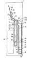
図1および図2において、11は循環式硬貨入出金機の機体で、この機体11の操作者側(操作面側)12である前面上部に入金口と出金口とを兼ねて図示しない入出金口シャッタで開閉される入出金口13が形成され、この入出金口13の内側に硬貨を受け入れる硬貨受部14が配設されている。この硬貨受部14は上面を開口した受皿14aを有し、この受皿14aに硬貨を受け入れるとともに受皿14aの回動によって受け入れた硬貨を下方のシュート15に放出可能としている。硬貨受部14には、受皿14a内の硬貨の有無を検知する図示しないセンサが配設されている。
【0032】
機体11の前側下部にはシュート15などを通じて送り込まれる硬貨を受け入れる硬貨貯留装置18が配設されている。この硬貨貯留装置18は、図2および図5に示すように、垂直に対して上側が機体11の左側面方向(図2の左側)へ所定角度傾いて軸支された硬貨繰出部としての回転円盤19、およびこの回転円盤19の表面側に配設されたホッパ20を有し、これら回転円盤19とホッパ20との間に送り込まれる硬貨を貯留する硬貨貯留部21が形成されている。
【0033】
回転円盤19の表面周縁近傍に硬貨を掻き上げるための複数の突起22が一定間隔で突設されており、回転円盤19の回転により硬貨貯留部21内の硬貨を各突起22で1枚ずつ掻き上げながら回転円盤19の上部位置から1枚ずつ繰り出し可能としている。
【0034】
ホッパ20には、回転円盤19によってホッパ20内から繰り出されずに残留する異物を排出するために、ホッパ20の底部を開閉する開閉部23が開閉可能に配設されている。開閉部23の下方には開閉部23の開放によって放出される異物を受け入れて機体11の前面下部に開口形成された異物排出口24に送り込む異物排出シュート25が配設されている。
【0035】
また、図1および図5に示すように、回転円盤19の上部位置には、硬貨貯留装置18から1枚ずつ繰り出される硬貨を受け入れて1枚ずつ間隔をあけた分離状態で搬送する硬貨通路装置28の硬貨通路29の始端部が接続されている。この硬貨通路29は、硬貨貯留装置18の上部位置から斜め上後方へ向けて傾斜状に形成される識別通路域30、この識別通路域30の末端から後方へ向けて略水平状に形成される分岐通路域31、この分岐通路域31の末端から上方に円弧状に折り返して前方へ向けて形成されるとともに硬貨通路29の終端である末端部が硬貨受部14に接続される出金通路域32が形成されている。
【0036】
硬貨通路29は、回転円盤19と同じの傾斜状態であって、硬貨を垂直に対して上側が機体11の左側面方向(図2の左側)へ所定角度傾いた傾斜状態で搬送する通路板33を有し、この通路板33の下縁には搬送する硬貨の周縁下部を支持する案内縁34a,34bが形成されている。
【0037】
硬貨通路29上には、硬貨貯留装置18から1枚ずつ繰り出される硬貨を1枚ずつ間隔をあけた分離状態で搬送する搬送手段としての搬送ベルト35が配設されている。この搬送ベルト35は、無端状で、プーリ36,37,38を含む複数のプーリによって各通路域30〜32に沿って懸架されており、硬貨を通路板33に押し付けながら搬送する。搬送ベルト35には硬貨を1枚ずつ間隔をあけた分離状態で搬送する突起39が通路板33に対向する面に所定間隔毎に突設されている。そして、通路板33の上面と搬送ベルト35の突起39の対向面との間隙は接触しない微小間隙、通路板33の上面と搬送ベルト35の突起39以外の対向面部との間隙は処理対象とする最小厚み硬貨の厚みよりやや小さい間隙に設定されている。
【0038】
硬貨通路29の識別通路域30には、搬送する硬貨の適正、不適正、金種などを識別する材質センサやイメージセンサなどにて構成される硬貨識別部41が配設されている。この硬貨識別部41より搬送方向下流側には入金時のオーバーフロー硬貨を分岐するオーバーフロー硬貨分岐部としての種類別分岐部42が配設されている。
【0039】
硬貨通路29の分岐通路域31には、上流側から順に、硬貨識別部41にて識別された硬貨を例えば1円、5円、10円、50円、100円、500円硬貨の金種別に分岐する金種別分岐部としての種類別分岐部43a〜43f、補充時の余剰補充硬貨および入金承認時のオーバーフロー硬貨や回収時の回収硬貨などを分岐する第1の硬貨収納カセット用分岐部としての種類別分岐部44、補充時および回収時のリジェクト硬貨や入金時および出金時の取り忘れ硬貨などを分類する第2の硬貨収納カセット用分岐部としての種類別分岐部45がそれぞれ形成されている。
【0040】
各種類別分岐部42,43a〜43f,44,45は、略共通に構成されており、例えば図6に種類別分岐部43a〜43fの一部を示すように、通路板33に分岐孔46がそれぞれ開口形成されるとともに、これら分岐孔46を開閉する分岐部材47がそれぞれ配設されている。各分岐部材47は、硬貨通路29の上流側が開閉するように通路板33に回動自在に軸支されているとともに、図示しないロータリーソレノイドにて開閉駆動される。各分岐部材47には、開口時に搬送ベルト35との干渉を避ける切欠部48が形成されている。
【0041】
通路板33の各種類別分岐部42,43a〜43f,44,45の上流側および下流側に、硬貨通路29内を搬送する硬貨を検知する図示しない硬貨検知センサ(図8に示すセンサ群123に含まれる)が配設されている。そして、各種類別分岐部42,43a〜43f,44,45の各分岐部材47は、硬貨識別部41での識別結果と硬貨検知センサとの両条件にて、ロータリーソレノイドにより開放駆動され、該当硬貨のみを各種類別分岐部42,43a〜43f,44,45から分岐し、該当硬貨以外の硬貨を硬貨通路29の下流側へ通過させる。
【0042】
図1に示すように、種類別分岐部42には、この種類別分岐部42で分岐した硬貨を受け入れて下方へ案内するシュート50が接続されている。図1および図2に示すように、各種類別分岐部43a〜43fには、各種類別分岐部43a〜43fで分岐した硬貨を受け入れて下方へ案内する金種別のシュート51が接続されている。図1、図2および図4に示すように、各種類別分岐部44,45には、各種類別分岐部44,45で分岐した硬貨を受け入れて下方へ案内するシュート52,53がそれぞれ接続されている。
【0043】
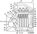
また、図1および図2に示すように、機体11内には、種類別分岐部43a〜43fのシュート51の下方に入金一時保留装置56が配設され、この入金一時保留装置56の下方に金種別硬貨収納投出装置57が配設され、この金種別硬貨収納投出装置57の右側面側(図2の右側)の底部に搬送コンベヤ手段58が配設され、種類別分岐部44,45のシュート52,53の下方に硬貨収納カセット59が配設されている。
【0044】
入金一時保留装置56は、入金時に種類別分岐部43a〜43fで分岐されてシュート51で導かれる硬貨を受け入れるとともに所定枚数の硬貨を上下方向に重積して一時保留するもので、金種別に硬貨を上下方向に重積する筒状の開口を有する一時保留部62、およびこの一時保留部62の下面を開閉する投出板63などで構成されている。一時保留部62は、図示しない駆動機構により、投出板63で下面開口が閉塞されていてシュート51から硬貨を受け入れるとともに重積状態で一時保留可能とする定位置と、この定位置から機体11の右側面側(図2の右側)の搬送コンベヤ手段58上に移動して投出板63に対して相対的に開放される下面開口から一時保留硬貨を放出する返却位置との間で移動する。
【0045】
また、図1および図2に示すように、金種別硬貨収納投出装置57は、カセット方式で機体11内に着脱可能に装着される金種別の収納筒部66を有し、この収納筒部66の上方から硬貨の収納および投出を可能としている。収納筒部66の上方には投出板63が配設され、この投出板63は、図示しない駆動機構により、収納筒部66の上方の前進位置と、この前進位置より機体11の左側面側(図2の左側)の後退位置との間で往復移動する。そして、投出板63が定位置にあるとき一時保留部62の下面開口を閉塞して硬貨の一時保留を可能とし、この一時保留部62に一時保留した硬貨の収納時に投出板63が図2左方向の後退位置に移動し、一時保留部62の硬貨を収納筒部66に収納させ、また、一時保留部62が図2右方向の返却位置に移動した状態で、かつ収納筒部66内の硬貨を上昇させて最上位硬貨を一時保留部62の下面で受け止めた状態において、投出板63の往復移動により、収納筒部66の最上位の硬貨から順に投出可能としている。
【0046】
各収納筒部66内には重積硬貨を支承する支承部材67がそれぞれ上下動可能に配置され、これら各支承部材67が各収納筒部66に上下方向に形成された案内溝68を通じて収納筒部66に対し機体11の左側面側(図2の左側)に配置された駆動機構69に着脱可能に連結され、この駆動機構69によって各支承部材67がそれぞれ独立して上下動する。そして、収納筒部66内からの硬貨の投出時に支承部材67が上昇して最上位の硬貨を一時保留部62の下面に押し付けるとともに、収納筒部66内への硬貨の収納時に支承部材67が下降して硬貨を収納可能としている。
【0047】
なお、一時保留部62の硬貨を収納筒部66へ収納させる場合は、支承部材67が上昇して支承部材67上の重積硬貨上面を投出板63の下面近傍に位置させ、次に投出板63の退避により一時保留硬貨が重積状収納硬貨の上に載り、支承部材67の下降で重積硬貨上面が投出板63の下部近傍へ下降されて停止され、次に投出板63が閉じられて一時保留硬貨の収納が終わる。
【0048】
また、図1および図2に示すように、搬送コンベヤ手段58は、金種別硬貨収納投出装置57の右側面域(図2の右側)に沿って機体11の底部に略水平状に配置される受収コンベヤ域72、この受収コンベヤ域72の前端から斜め上前方の硬貨貯留装置18に接続される送出コンベヤ域73を有し、受収コンベヤ域72に受収した硬貨を硬貨貯留装置18に順次送り込む。これらコンベヤ域72,73上の両側に受収ガイド部材74が配設されるとともに受収コンベヤ域72の後端側に受収ガイド部材75が配設され、受収コンベヤ域72上の受収ガイド部材74,75で囲まれた空間に硬貨を受収する硬貨受収部76が形成されている。
【0049】
受収コンベヤ域72上の硬貨受収部76には、入金時に種類別分岐部42で分岐してシュート50で導かれるオーバーフロー硬貨を受収可能とし、硬貨収納カセット59が備える硬貨収納部86から全量放出される硬貨を全量受収可能とし、金種別硬貨収納投出装置57から全て投出される硬貨を受収可能としている。例えば、硬貨受収部76の最大受収枚数は1100枚、硬貨収納カセット59の硬貨収納部86の最大収納枚数は1100枚、金種別硬貨収納投出装置57の最大収納枚数は700枚程度に設定されている。
【0050】
搬送コンベヤ手段58は、無端状のベルト77を有し、このベルト77が複数のプーリ78に懸架されて各コンベヤ域72,73が形成されている。図7に示すように、ベルト77は、平ベルトで、その幅は処理する最大径の硬貨(図中には符号Cで示す)の直径より広い幅で最小径硬貨が径方向に2枚入らない幅に形成されており、ベルト77の表面にはその搬送方向に沿って処理する最大径の硬貨の直径より広く最小径硬貨が径方向に2枚入らない所定のピッチ毎に複数の突起79が形成されている。突起79は、断面四角形で、ベルト幅方向に3つが並び、ベルト77の表面から例えば4mm程度突出していて2枚の硬貨が同時に係合可能としている。そして、ベルト77の回転駆動により、受収コンベヤ域72に受収した硬貨を突起79に引っ掛けて硬貨貯留装置18に順次搬送可能としている。
【0051】
両側の受収ガイド部材74には、ベルト77の表面側に突出するガイド部80が形成され、このガイド部80に硬貨をベルト77の表面に案内する傾斜面81が形成されている。これら両側のガイド部80の内側間隔は最大径の硬貨の直径よりやや広くかつ最小径硬貨の直径の2枚分より狭く設定されている。また、受収コンベヤ域72と送出コンベヤ域73との鈍角状の交差域は、ガイド部材80にて鈍角状にガイド支持されている。
【0052】
また、図1、図2および図4に示すように、硬貨収納カセット59は、機体11の後部側に形成されたカセット装着部84に対しその機体11の右側面側(図4の左側)から着脱可能に装着されており、斜めにした硬貨収納カセット59の下部側を機体11に抜き差し、機体11に装着した硬貨収納カセット59の下部側を支点として上部側を機体11の内外に移動させることができる。
【0053】
図3に示すように、硬貨収納カセット59は、運搬可能な縦長箱状のカセット本体85を有し、このカセット本体85内の上部側に硬貨の全量放出を可能とする硬貨収納部86と硬貨を放出しない硬貨非放出収納部87とが左右方向に並んで区画形成され、これら収納部86,87の下側に補充リジェクト硬貨収納部88、回収リジェクト硬貨収納部89および取り忘れ硬貨収納部90が前後方向に並んで区画形成されている。硬貨非放出収納部87の最大収納枚数は800枚程度に設定されている。
【0054】
各収納部86,87の上面には硬貨を受収する受収口91,92がそれぞれ形成され、これら受収口91,92を一体に開閉する受収口シャッタ93がカセット本体85内に開閉可能に配設されている。各収納部88〜90の左側面上部には硬貨を受収する図示しない受収口がそれぞれ形成され、これら受収口を一体に開閉する図示しない受収口シャッタがカセット本体85内に開閉可能に配設されている。これら受収口シャッタ93を含む受収口シャッタは、硬貨収納カセット59を機体11内のカセット装着部84に装着することにより自動的に開放され、硬貨収納カセット59を機体11内のカセット装着部84から取り外すことにより自動的に閉塞される。
【0055】
硬貨収納部86の下部側には、カセット本体85の前面に開口する硬貨放出口94が形成され、硬貨収納部86の底部に硬貨を自重で硬貨放出口94から放出させるシュート状の傾斜底面95が形成され、硬貨放出口94を開閉する開閉板としての第1の開閉板96が上下方向に開閉可能に配設されている。傾斜底面95は、硬貨放出口94へ向けて下降傾斜するとともに傾斜方向と交差する方向の断面が円弧状に形成され、硬貨収納部86内の硬貨が傾斜底面に貼り付くのを防止して確実に全量放出可能としている。これら傾斜底面95および第1の開閉板96などによって、硬貨放出口94から硬貨収納部86内の硬貨を全量放出する全量放出手段97が構成されている。
【0056】
硬貨収納部86の傾斜底面95と閉塞状態の第1の開閉板96とのなす隅部の硬貨有無検知位置に対応して、カセット本体85を左右方向に貫通するセンサ孔98が形成されている。なお、センサ孔98は、硬貨収納部86内に開口して硬貨有無検知を許容するが、図3(c)に示すように、硬貨非放出収納部87ではこの硬貨非放出収納部87内の隅部に形成された膨出部99を貫通し、硬貨非放出収納部87の硬貨は硬貨有無検知に無関係としている。
【0057】
また、図3に示すように、カセット装着部84には、硬貨収納カセット59の硬貨放出口94が臨む硬貨受入口102が形成され、この硬貨受入口102を開閉する第2の開閉板103が上下方向に開閉可能に配設されている。硬貨受入口102の内側には図1に示す受収ガイド部材75の上端が連続され、硬貨収納カセット59の硬貨収納部86から全量放出される硬貨を搬送コンベヤ手段58の受収コンベヤ域72上の硬貨受収部76に受収可能としている。
【0058】
カセット装着部84の両側には硬貨収納カセット59のセンサ孔98を通じて硬貨収納部86内の硬貨の有無を検知する光学式の硬貨有無検知センサ104が配設されている。
【0059】
また、図1、図2および図4に示すように、種類別分岐部44のシュート52の下部側が2つのシュート部52a,52bに分岐され、一方のシュート部52aは硬貨収納カセット59の受収口91の上方に配置され、他方のシュート部52bは硬貨収納カセット59の受収口92の上方に配置され、2つのシュート部52a,52b間に配置される図示しない切換部材によって種類別分岐部44で分岐された硬貨の受収先が切り換えられる。
【0060】
種類別分岐部45のシュート53は硬貨収納カセット59の側部に配設され、このシュート53の下部側が3つのシュート部53a,53b,53cに分岐され、1つ目のシュート部53aは補充リジェクト硬貨収納部88の受収口に配置され、2つ目のシュート部53bは回収リジェクト硬貨収納部89の受収口に配置され、3つ目のシュート部53cは取り忘れ硬貨収納部90の受収口に配置されている。シュート部53a,53b間およびシュート部53b,53c間にそれぞれ配置される切換部材107,108によって種類別分岐部45で分岐された硬貨の受収先が切り換えられる。
【0061】
そして、循環式硬貨入出金機は、硬貨収納カセット59の硬貨収納部86から補充硬貨を受け入れて金種識別し、補充可能な硬貨は金種別に分岐して金種別硬貨収納投出装置57へ送り込む補充搬送系111と、操作者側12から投入される入金硬貨を受け入れて金種識別し、入金正規硬貨は入金一時保留装置56に一時保留し、入金承認時に出金に使用可能な硬貨は金種別硬貨収納投出装置57へ送り込む入金搬送系112と、金種別硬貨収納投出装置57から投出される出金硬貨を受け入れて金種識別し、正規硬貨は操作者側12へ搬送する出金搬送系113と、硬貨収納カセット59の硬貨収納部86から全量放出される硬貨や金種別硬貨収納投出装置57から全て投出される硬貨を受け入れて金種識別し、元の硬貨収納カセット59の硬貨収納部86や金種別硬貨収納投出装置57へ戻す精査搬送系114と、硬貨収納カセット59の硬貨収納部86から全量放出される硬貨や金種別硬貨収納投出装置57から全て投出される硬貨を受け入れて金種識別し、金種識別した硬貨を硬貨収納カセット59に回収する精査回収搬送系115とを備えている。これら補充搬送系111、入金搬送系112、出金搬送系113、精査搬送系114および精査回収搬送系115は、硬貨貯留装置18、硬貨通路装置28および搬送コンベヤ手段58を共用して構成されている。
【0062】
出金搬送系113は硬貨通路装置28から操作者側12へ硬貨を搬送する出金手段116が備え、この出金手段116には硬貨通路装置28の出金通路域32および搬送ベルト35などが含まれる。
【0063】
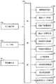
また、図8に、制御部121によって循環式硬貨入出金機を制御する概略制御構成を示し、この制御部121には指令操作部122、センサ群123、硬貨識別部41が接続され、これらからの情報を制御部121に入力し、また、制御部121には補充搬送系111、入金搬送系112、出金搬送系113、精査搬送系114、精査回収搬送系115、開閉板駆動部124、搬送コンベヤ手段58が接続され、これらの駆動を制御部121で制御する。
【0064】
指令操作部122は、各種の処理モードを指定したり、スタート、ストップを指令する。センサ群123は、各搬送系のセンサなど、機体11内に配置される各センサを含み、これら各センサからの情報を制御部121に出力する。開閉板駆動部124は、機体11のカセット装着部84の近傍に配設され、カセット装着部84に装着された硬貨収納カセット59の第1の開閉板96および機体11の第2の開閉板103を連動させて開閉する。
【0065】
また、図9に、制御部121によって循環式硬貨入出金機を制御する詳細制御構成を示し、この制御部121には指令操作部122、センサ群123、硬貨識別部41が接続され、これらからの情報を制御部121に入力し、また、制御部121には開閉板駆動部124、搬送コンベヤ手段58、硬貨貯留装置18の回転円盤19を回転駆動する回転円盤駆動部125、硬貨通路装置28の搬送ベルト35を回行駆動する搬送ベルト駆動部126、各分岐部材47を切換駆動する分岐部材駆動部127、シュート52の切換部材およびシュート53の切換部材107,108を切換駆動する切換部材駆動部128、硬貨受部14の受皿14aを回動駆動する受皿駆動部129、入金一時保留装置56の一時保留部62を移動させる一時保留部駆動部130、投出板63を移動させる投出板駆動部131、支承部材67を介して収納筒部66内の重責硬貨を上下に移動させる駆動機構69の重積硬貨上下駆動部132が接続され、これらの駆動を制御部121で制御する。
【0066】
そして、制御部121は、以下の機能を有している。
【0067】
補充時に、搬送コンベヤ手段58に硬貨収納カセット59から全量放出された初期補充硬貨または途中補充硬貨を補充搬送系111を通じて金種別硬貨収納投出装置57へ補充させるとともに、金種別硬貨収納投出装置57への補充の必要がない硬貨すなわち金種別硬貨収納投出装置57に送り込めない余剰補充硬貨を補充搬送系111を通じて硬貨収納カセット59の硬貨収納部86へ回収収納させる補充動作の機能。
【0068】
入金時に、搬送コンベヤ手段58に一時保留した入金オーバーフロー硬貨を入金承認時に硬貨を収納する入金搬送系112を通じて硬貨収納カセット59の硬貨収納部86へ回収収納させる機能。
【0069】
精査時に、搬送コンベヤ手段58に硬貨収納カセット59の硬貨収納部86から全量放出された硬貨を精査搬送系114を通じて精査した後に硬貨収納カセット59の硬貨収納部86へ戻す第1の精査動作、および搬送コンベヤ手段58に金種別硬貨収納投出装置57から投出された全量の硬貨を精査搬送系114を通じて精査した後に金種別硬貨収納投出装置57へ戻す第2の精査動作の機能。
【0070】
回収時に、搬送コンベヤ手段58に硬貨収納カセット59の硬貨収納部86から全量放出された回収硬貨を精査回収搬送系115を通じて精査した後に硬貨収納カセット59へ回収させる第1の回収動作、および搬送コンベヤ手段58に金種別硬貨収納投出装置57から投出された全量の硬貨を精査回収搬送系115を通じて精査した後に硬貨収納カセット59へ回収させる第2の回収動作の機能。
【0071】
次に、本実施の形態の作用を説明する。
【0072】
まず、初期補充処理について図10を参照して説明する。
【0073】
循環式硬貨入出金機の外部で初期補充硬貨を硬貨収納部86に収納した硬貨収納カセット59を、循環式硬貨入出金機の機体11内のカセット装着部84に装着する。硬貨収納カセット59の装着により、各受収口シャッタ(受収口シャッタ93を含む)を開放し、第1の開閉板96が開閉板駆動部124側と係合して第1の開閉板96を開閉可能とする。硬貨有無検知センサ104に硬貨収納カセット59のセンサ孔98が対向し、硬貨有無検知センサ104の検知光が硬貨収納部86に収納されている初期補充硬貨で遮光されて硬貨ありを検知する。
【0074】
係員が指令操作部122で初期補充モードを指定し、スタートを指令することにより、硬貨貯留装置18、硬貨通路装置28および搬送コンベヤ手段58の駆動を開始し、開閉板駆動部124によって硬貨収納カセット59の第1の開閉板96および第2の開閉板103を連動させて開放する。これら第1の開閉板96および第2の開閉板103の開放移動により硬貨放出口94および硬貨受入口102を開放し、硬貨収納部86に収納していた初期補充硬貨を傾斜底面95の傾斜によって自重で硬貨放出口94から全量放出させ、硬貨受入口102を通じて、搬送コンベヤ手段58の受収コンベヤ域72上、つまり硬貨受収部76に全量受収させる。このとき、例えば、搬送コンベヤ手段58上の硬貨受収部76の最大受収枚数は1100枚、硬貨収納カセット59の硬貨収納部86の最大収納枚数は1100枚であるため、硬貨収納カセット59から全量放出する硬貨を搬送コンベヤ手段58上に全量受収できる。
【0075】
硬貨収納部86に収納していた初期補充硬貨を全量放出することで、硬貨有無検知センサ104の検知光がセンサ孔98を通じて透光状態となり、この透光状態が所定時間以上継続することで硬貨収納部86の硬貨なしを検知する。開閉板駆動部124によって第1の開閉板96および第2の開閉板103を連動して閉塞し、これら第1の開閉板96および第2の開閉板103の閉塞移動により硬貨放出口94および硬貨受入口102を閉塞する。これにより、硬貨収納部86に硬貨の受収が可能な状態とする。なお、硬貨収納カセット59から搬送コンベヤ手段58に放出された全量放出硬貨CAは硬貨放出口94および硬貨受入口102より下方に位置し、各開閉板96,103とも閉塞移動可能としている。
【0076】
搬送コンベヤ手段58のベルト77の回転駆動により、受収コンベヤ域72上の初期補充硬貨を送出コンベヤ域73を通じて硬貨貯留装置18に順次送り込む。
【0077】
硬貨貯留装置18では回転円盤19が回転し、搬送コンベヤ手段58から送り込まれた初期補充硬貨を1枚ずつ硬貨通路装置28に繰り出す。
【0078】
硬貨通路装置28では硬貨貯留装置18から繰り出される初期補充硬貨を受け入れて1枚ずつ間隔をあけた分離状態で搬送し、初期補充硬貨の搬送途上で硬貨識別部41により識別する。
【0079】
硬貨識別部41での識別の結果、正規の初期補充硬貨は種類別分岐部43a〜43fで金種別に分岐し、シュート51および入金一時保留装置56の一時保留部62を通じて、金種別硬貨収納投出装置57の収納筒部66に収納する。入金一時保留装置56の一時保留部62は投出板63が後退位置(図2に示す位置より左方向に移動した位置)に移動して底面が開口された状態にあり、シュート51から一時保留部62に送り込まれた初期補充硬貨を収納筒部66に直接収納する。このとき、収納筒部66内の重積硬貨の上面を収納筒部66の上端近傍に位置させておくことにより、初期補充硬貨の落下距離を少なくし、硬貨立ちなどが発生するのを防止できる。収納筒部66内に初期補充硬貨を1枚受け入れる度に支承部材67とともに重積硬貨を1枚分下降させ、次の初期補充硬貨の収納を許容する。
【0080】
制御部121では硬貨識別部41での識別結果から金種別硬貨収納投出装置57の各収納筒部66に収納する初期補充硬貨の枚数をカウントし、カウント値が予め設定された満杯量に達した金種については、それ以降に硬貨識別部41で識別される正規の初期補充硬貨をオーバーフロー硬貨として取り扱う。このオーバーフロー硬貨は、該当する金種の種類別分岐部43a〜43fで分岐せずに下流側の種類別分岐部44で分岐し、シュート52の切換部材およびシュート部52aを通じて硬貨収納カセット59の硬貨収納部86に回収収納させる。このとき、硬貨収納部86の硬貨放出口94は第1の開閉板96によって既に閉塞されているため、硬貨収納部86に回収した初期補充硬貨は放出されることなく収納状態に保たれる。また、硬貨収納部86に初期補充硬貨を回収することで、硬貨有無検知センサ104の検知光が遮光されて硬貨ありを検知する。
【0081】
硬貨識別部41での識別の結果、不適正と判断されたリジェクト硬貨は、最下流の種類別分岐部45まで搬送してその種類別分岐部45で分岐し、シュート53の切換部材107およびシュート部53aを通じて硬貨収納カセット59の補充リジェクト硬貨収納部88に回収収納させる。
【0082】
そして、硬貨識別部41で初期補充硬貨の識別が所定時間以上なくなれば、硬貨貯留装置18、硬貨通路装置28および搬送コンベヤ手段58を停止し、初期補充処理を完了する。なお、金種別硬貨収納投出装置57の各収納筒部66が満杯となったときの合計枚数は例えば800枚であり、搬送コンベヤ手段58の最大受収量は例えば1100枚であるので、金種別硬貨収納投出装置57から搬送コンベヤ手段58への全量放出が可能である。
【0083】
次に、入金処理について図11ないし図14を参照して説明する。
【0084】
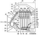
図11に入金処理時における入金送り込み動作を示し、操作者が指令操作部122で入金を指令することにより、入出金口13の入出金口シャッタを開放し、さらに、操作者が入金硬貨を入出金口13を通じて硬貨受部14に投入することにより、硬貨受部14の受皿14a上の硬貨を図示しないセンサで検知して入出金口シャッタを閉鎖する。硬貨貯留装置18および硬貨通路装置28の駆動を開始し、硬貨受部14の受皿14aの回動によって投入された入金硬貨をシュート15に放出し、シュート15を通じて硬貨貯留装置18に送り込む。硬貨受部14では入金硬貨の放出後に受皿14aを戻して硬貨の受収を可能な状態とする。
【0085】
硬貨貯留装置18に送り込んだ入金硬貨は、上述したように硬貨貯留装置18から硬貨通路装置28に1枚ずつ送り込み、硬貨識別部41で識別する。
【0086】
硬貨識別部41での識別の結果、正規の入金硬貨は種類別分岐部43a〜43fで金種別に分岐し、シュート51を通じて入金一時保留装置56に金種別に一時保留する。入金一時保留装置56では、図2に示すように、一時保留部62の底面を投出板63で閉塞しており、一時保留部62に受け入れた入金硬貨を上下方向に重積状態で一時保留する。
【0087】
制御部121では硬貨識別部41での識別結果から入金一時保留装置56に一時保留する入金硬貨の枚数をカウントし、カウント値が予め設定された一時保留の満杯量に達した金種については、それ以降に硬貨識別部41で識別される正規の入金硬貨を入金オーバーフロー硬貨として取り扱う。この入金オーバーフロー硬貨は、最上流の種類別分岐部42で分岐し、シュート50を通じて搬送コンベヤ手段58の受収コンベヤ域72に送り込み、一括して一時保留する。
【0088】
硬貨識別部41での識別の結果、不適正と判断されたリジェクト硬貨は、いずれの種類別分岐部42〜45でも分岐せず、出金通路域32を通じて硬貨通路29の末端まで搬送し、硬貨受部14に送り込む。このとき、硬貨受部14の受皿14aはリジェクト硬貨を受収可能な状態にある。入出金口13の入出金口シャッタを開放し、操作者が硬貨受部14からリジェクト硬貨を取り出すことによって入出金口シャッタを閉鎖する。
【0089】
そして、硬貨識別部41で硬貨の識別が所定時間以上なくなれば、硬貨貯留装置18および硬貨通路装置28を停止して入金送り込み動作を完了し、その後、入金硬貨の識別結果を操作者に対して表示し、入金の確認をとる。
【0090】
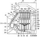
図12に、操作者が指令操作部122によって入金承認の操作をした場合で、入金オーバーフロー硬貨がなかった場合の入金収納動作を示す。入金一時保留装置56の投出板63を後退位置(図2に示す位置より左方向に移動した位置)に移動させ、一時保留部62の底面を開口させ、重積状態に一時保留させていた一時保留硬貨を金種別硬貨収納投出装置57の収納筒部66に収納させる。このとき、収納筒部66内の重積硬貨の上面を収納筒部66の上端近傍に位置させておくことにより、硬貨の落下距離を少なくし、硬貨立ちなどが発生するのを防止できる。収納筒部66内に一時保留硬貨を受け入れる枚数に応じて支承部材67とともに重積硬貨を下降させ、一時保留硬貨を収納筒部66内に収納する。これにより、入金送り込み動作から入金収納動作までの一連の入金処理を完了する。
【0091】
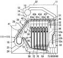
図13に、操作者が指令操作部122によって入金承認の操作をした場合で、入金オーバーフロー硬貨があった場合の入金収納動作を示す。入金一時保留装置56に一時保留していた一時保留硬貨は、上述したように投出板63の後退位置への移動によって金種別硬貨収納投出装置57の収納筒部66に収納させる。
【0092】
搬送コンベヤ手段58の受収コンベヤ域72に一括一時保留していた入金オーバーフロー硬貨は、硬貨貯留装置18、硬貨通路装置28および搬送コンベヤ手段58の駆動により、上述したように搬送コンベヤ手段58から硬貨貯留装置18を通じて硬貨通路装置28に送り込み、硬貨通路装置28の種類別分岐部44で分岐し、シュート52の切換部材およびシュート部52aを通じて硬貨収納カセット59の硬貨収納部86に収納させる。なお、例えば、硬貨収納カセット59の硬貨収納部86の硬貨収納量が、最大収納枚数内で予め任意に設定した途中補充処理における全量放出量に達している場合には、シュート52の切換部材を切り換え、入金オーバーフロー硬貨を、シュート52の切換部材およびシュート部52bを通じて硬貨非放出収納部87に収納させる。
【0093】
硬貨識別部41で入金オーバーフロー硬貨の識別が所定時間以上なくなれば、硬貨貯留装置18、硬貨通路装置28および搬送コンベヤ手段58を停止し、入金送り込み動作から入金収納動作までの一連の入金処理を完了する。
【0094】
これら入金一時保留装置56および搬送コンベヤ手段58からの一時保留硬貨の収納動作は並行処理が可能で、特に搬送コンベヤ手段58からの一時保留硬貨を金種別に分岐することなく硬貨収納カセット59の硬貨収納部86に収納させることで、処理時間を短くし、次の処理に迅速に移ることができる。
【0095】
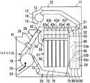
図14に、操作者が指令操作部122によって入金不承認の操作をした場合を示す。入金一時保留装置56の一時保留部62を搬送コンベヤ手段58の受収コンベヤ域72の上方の返却位置に移動させ、一時保留部62に一時保留していた全ての硬貨を搬送コンベヤ手段58の受収コンベヤ域72に放出する。このとき、搬送コンベヤ手段58の受収コンベヤ域72に入金オーバーフロー硬貨を一時保留していた場合には、一時保留部62から放出される硬貨と一緒になる。
【0096】
搬送コンベヤ手段58の受収コンベヤ域72上の返却硬貨は、硬貨貯留装置18、硬貨通路装置28および搬送コンベヤ手段58の駆動により、上述したように搬送コンベヤ手段58から硬貨貯留装置18を通じて硬貨通路装置28に送り込み、硬貨通路29の末端まで搬送して硬貨受部14の受皿14a(受入可能な上向き位置にある)に送り込む。全ての返却硬貨を硬貨受部14の受皿14aに送り込んだら、硬貨貯留装置18、硬貨通路装置28および搬送コンベヤ手段58を停止し、入出金口13の入出金口シャッタを開放し、操作者が硬貨受部14の受皿14aから返却硬貨を取り出すことによって入出金口シャッタを閉鎖する。これにより、入金送り込み動作から入金返却動作までの一連の処理を完了する。
【0097】
次に、出金処理について図15を参照して説明する。
【0098】
操作者が指令操作部122によって出金貨幣値(金額または金種と枚数)を入力し、スタートを指令することにより、金種別硬貨収納投出装置57の出金金種に該当する収納筒部66において、収納されている重積硬貨を支承部材67によって上昇させ、収納筒部66の上部を閉塞する位置に位置される一時保留部62の下面に重積硬貨を当接させ、往復移動させる投出板63によって最上位の重積硬貨つまり出金硬貨を収納筒部66から搬送コンベヤ手段58の受収コンベヤ域72上に投出する。続けて投出する金種がある場合には、同様に重積硬貨を上昇させ投出板63によって投出する。出金金種に該当しない金種および出金枚数分を投出し終えた金種については、重積硬貨を下降させ、硬貨の投出を停止する。
【0099】
搬送コンベヤ手段58の受収コンベヤ域72上に投出された出金硬貨は、硬貨貯留装置18、硬貨通路装置28および搬送コンベヤ手段58の駆動により、上述したように搬送コンベヤ手段58から硬貨貯留装置18を通じて硬貨通路装置28に送り込み、硬貨識別部41で識別する。
【0100】
硬貨識別部41での識別の結果、正規の出金硬貨は硬貨通路29の末端まで搬送して硬貨受部14に送り込む。
【0101】
不適正と判断されたリジェクト硬貨は種類別分岐部44で分岐し、シュート52の切換部材およびシュート部52aを通じて硬貨収納カセット59の硬貨収納部86に回収収納させる。リジェクト硬貨が発生した場合には、出金貨幣値に不足する金種硬貨を金種別硬貨収納投出部57から再投出させる。
【0102】
出金貨幣値分の出金硬貨を硬貨受部14に送り込んだら、硬貨貯留装置18、硬貨通路装置28および搬送コンベヤ手段58を停止し、入出金口13の入出金口シャッタを開放し、操作者が硬貨受部14の受皿14aから出金硬貨を取り出すことによって入出金口シャッタを閉鎖する。これにより、出金処理を完了する。
【0103】
次に、途中補充処理について図16を参照して説明する。
【0104】
出金処理によって金種別硬貨収納投出装置57の金種別の硬貨の収納量が所定量以下に低下した場合に、途中補充処理を自動的に開始する。この途中補充処理では、初期補充処理と同様に、硬貨貯留装置18、硬貨通路装置28および搬送コンベヤ手段58の駆動を開始し、開閉板駆動部124によって硬貨収納カセット59の第1の開閉板96および第2の開閉板103を連動させて開放する。これら第1の開閉板96および第2の開閉板103の開放移動により硬貨放出口94および硬貨受入口102を開放し、硬貨収納部86に収納していた補充硬貨を傾斜底面95の傾斜によって自重で硬貨放出口94から全量放出させ、硬貨受入口102を通じて、搬送コンベヤ手段58の受収コンベヤ域72上、つまり硬貨受収部76に全量受収させる。
【0105】
硬貨収納部86に収納していた補充硬貨を全量放出することで、硬貨有無検知センサ104の検知光がセンサ孔98を通じて透光状態となり、この透光状態が所定時間以上継続することで硬貨収納部86の硬貨なしを検知する。開閉板駆動部124によって第1の開閉板96および第2の開閉板103を連動して閉塞し、これら第1の開閉板96および第2の開閉板103の閉塞移動により硬貨放出口94および硬貨受入口102を閉塞する。これにより、硬貨収納部86に硬貨の受収が可能な状態とする。
【0106】
搬送コンベヤ手段58の受収コンベヤ域72に全量受収した補充硬貨は、硬貨貯留装置18、硬貨通路装置28および搬送コンベヤ手段58の駆動により、上述したように搬送コンベヤ手段58から硬貨貯留装置18を通じて硬貨通路装置28に送り込み、硬貨識別部41で識別する。
【0107】
硬貨識別部41での識別の結果、正規の補充硬貨は、初期補充処理と同様に、種類別分岐部43a〜43fで金種別に分岐し、シュート51および入金一時保留装置56の底面が開口された一時保留部62を通じて、金種別硬貨収納投出装置57の収納筒部66に直接収納させる。
【0108】
制御部121では硬貨識別部41での識別結果から金種別硬貨収納投出装置57の各収納筒部66に収納する硬貨の枚数をカウントし、カウント値が予め設定された満杯量に達した金種については、それ以降に硬貨識別部41で識別する正規の補充硬貨をオーバーフロー硬貨として取り扱う。このオーバーフロー硬貨は、該当する金種の種類別分岐部43a〜43fで分岐せずに下流側の種類別分岐部44で分岐し、シュート52の切換部材およびシュート部52aを通じて硬貨収納カセット59の硬貨収納部86に回収収納させる。このとき、硬貨収納部86の硬貨放出口94は第1の開閉板96によって既に閉塞されているため、硬貨収納部86に回収した補充硬貨は放出されることなく収納状態に保たれる。また、硬貨収納部86に補充硬貨を回収することで、硬貨有無検知センサ104の検知光が遮光されて硬貨ありを検知する。
【0109】
硬貨識別部41での識別の結果、不適正と判断されたリジェクト硬貨は、オーバーフロー硬貨と同様に、種類別分岐部44で分岐し、シュート52の切換部材およびシュート部52aを通じて硬貨収納カセット59の硬貨収納部86に回収収納させる。
【0110】
そして、硬貨識別部41で補充硬貨の識別が所定時間以上なくなれば、硬貨貯留装置18、硬貨通路装置28および搬送コンベヤ手段58を停止し、途中補充処理を完了する。
【0111】
なお、硬貨収納カセット59の硬貨収納部86の硬貨収納量を適正に設定し、設定した硬貨収納量を超える硬貨は非放出収納部87に収納させるようにすることで、この途中補充処理において、硬貨収納カセット59の硬貨収納部86からの全量放出量を適正にし、補充処理時間の短縮を図ることができる。
【0112】
次に、精査処理について図17および図18を参照して説明する。
【0113】
係員が指令操作部122で精査処理を指定し、スタートを指令することにより、硬貨収納カセット59の硬貨収納部86に収納している硬貨を精査する第1の精査動作、および金種別硬貨収納投出装置57の収納筒部66に収納している硬貨を精査する第2の精査動作を実行する。
【0114】
図17に、硬貨収納カセット59の硬貨収納部86に収納している硬貨を精査する第1の精査動作を示す。第1の精査動作では、硬貨貯留装置18、硬貨通路装置28および搬送コンベヤ手段58の駆動を開始し、開閉板駆動部124によって硬貨収納カセット59の第1の開閉板96および第2の開閉板103を連動させて開放する。これら第1の開閉板96および第2の開閉板103の開放移動により硬貨放出口94および硬貨受入口102を開放し、硬貨収納部86に収納していた硬貨を傾斜底面95の傾斜によって自重で硬貨放出口94から全量放出させ、硬貨受入口102を通じて、搬送コンベヤ手段58の受収コンベヤ域72上、つまり硬貨受収部76に全量受収させる。
【0115】
硬貨収納部86に収納されていた硬貨を全量放出して、硬貨有無検知センサ104の検知光がセンサ孔98を通じて透光状態となり、この透光状態が所定時間以上継続することで硬貨収納部86の硬貨なしを検知する。開閉板駆動部124によって第1の開閉板96および第2の開閉板103を連動して閉塞し、これら第1の開閉板96および第2の開閉板103の閉塞移動により硬貨放出口94および硬貨受入口102を閉塞する。これにより、硬貨収納部86に硬貨の受収が可能な状態となる。
【0116】
搬送コンベヤ手段58の受収コンベヤ域72に全量受収した硬貨は、硬貨貯留装置18、硬貨通路装置28および搬送コンベヤ手段58の駆動により、上述したように搬送コンベヤ手段58から硬貨貯留装置18を通じて硬貨通路装置28に送り込み、硬貨識別部41で識別する。識別した硬貨は、種類別分岐部44で分岐し、シュート52の切換部材およびシュート部52aを通じて硬貨収納カセット59の硬貨収納部86に回収収納させる。このとき、硬貨収納部86の硬貨放出口94は第1の開閉板96によって既に閉塞されているため、硬貨収納部86に回収収納した硬貨は放出されることなく収納状態に保たれる。また、硬貨収納部86に硬貨を回収することで、硬貨有無検知センサ104の検知光が遮光されて硬貨ありを検知する。
【0117】
そして、硬貨識別部41で硬貨の識別が所定時間以上なくなれば、硬貨貯留装置18、硬貨通路装置28および搬送コンベヤ手段58を停止し、第1の精査動作を完了する。
【0118】
図18、金種別硬貨収納投出装置57の収納筒部66に収納している硬貨を精査する第2の精査動作を示す。指令操作部122で精査を指定し、スタートを指令することにより、第2の精査動作を開始する。この第2の精査動作では、金種別硬貨収納投出装置57の全ての金種の収納筒部66から全ての硬貨を投出させるか、金種別の収納筒部66から硬貨を順番に投出させて全ての硬貨を投出させる。すなわち、収納筒部66に収納されている重積硬貨を支承部材67によって上昇させ、往復移動する投出板63によって最上位の硬貨を収納筒部66から搬送コンベヤ手段58の受収コンベヤ域72上に投出する。このとき、例えば、搬送コンベヤ手段58上の硬貨受収部76の最大受収枚数は1100枚、金種別硬貨収納投出装置57の最大収納枚数は700枚であるため、金種別硬貨収納投出装置57から全て投出する硬貨を搬送コンベヤ手段58上に全量受収できる。
【0119】
搬送コンベヤ手段58の受収コンベヤ域72上に全て投出した硬貨は、硬貨貯留装置18、硬貨通路装置28および搬送コンベヤ手段58の駆動により、上述したように搬送コンベヤ手段58から硬貨貯留装置18を通じて硬貨通路装置28に送り込み、硬貨識別部41で識別する。識別した硬貨は、種類別分岐部43a〜43fで金種別に分岐し、シュート51および入金一時保留装置56の一時保留部62を通じて、金種別硬貨収納投出装置57の収納筒部66に収納する。入金一時保留装置56の一時保留部62は投出板63が後退位置(図2に示す位置より左方向に移動した位置)に移動して底面が開口された状態にあり、シュート51から一時保留部62に送り込まれた硬貨は収納筒部66に直接収納される。収納筒部66内の重積硬貨の上面を収納筒部66の上端近傍に位置させておくことにより、硬貨の落下距離を少なくし、硬貨立ちなどが発生するのを防止する。収納筒部66内に硬貨を1枚受け入れる度に支承部材67とともに重積硬貨を1枚分下降させ、後続の硬貨の収納を許容する。
【0120】
そして、硬貨識別部41で硬貨の識別が所定時間以上なくなれば、硬貨貯留装置18、硬貨通路装置28および搬送コンベヤ手段58を停止し、第2の精査処理を完了する。なお、第1、第2の精査動作連続モードを設け、子弟操作部122でこのモードを指定すると、第1の精査動作、この第1の精査動作終了で第2の精査動作を行うようにしてもよい。
【0121】
次に、回収処理について図19ないし図21を参照して説明する。
【0122】
図19に、機体11内の硬貨を精査なしに硬貨収納カセット59に回収する精査なし回収処理を示す。指令操作部で精査なし回収を指定し、スタートを指令することにより、精査なし回収処理を開始する。この精査なし回収処理では、金種別硬貨収納投出装置57の全ての金種の収納筒部66から全ての硬貨を投出させるか、金種別の収納筒部66から硬貨を順番に投出させて全ての硬貨を投出させる。すなわち、収納筒部66に収納されている重積硬貨を支承部材67によって上昇させ、往復移動する投出板63によって最上位の出金硬貨を収納筒部66から搬送コンベヤ手段58の受収コンベヤ域72上に投出する。
【0123】
搬送コンベヤ手段58の受収コンベヤ域72上に全て投出した硬貨は、硬貨貯留装置18、硬貨通路装置28および搬送コンベヤ手段58の駆動により、上述したように搬送コンベヤ手段58から硬貨貯留装置18を通じて硬貨通路装置28に送り込み、硬貨識別部41で識別する。識別の結果、正規の回収硬貨は、種類別分岐部44で分岐し、シュート52の切換部材およびシュート部52aを通じて硬貨収納カセット59の硬貨収納部86に、またはシュート52の切換部材およびシュート部52bを通じて硬貨収納カセット59の硬貨非放出収納部87に回収収納させる。
【0124】
硬貨識別部41での識別の結果、不適正と判断された回収リジェクト硬貨は、最下流の種類別分岐部45で分岐し、シュート53の切換部材108およびシュート部53bを通じて硬貨収納カセット59の回収リジェクト硬貨収納部89に回収収納させる。
【0125】
そして、硬貨識別部41で回収硬貨の識別が所定時間以上なくなれば、硬貨貯留装置18、硬貨通路装置28および搬送コンベヤ手段58を停止し、精査なし回収処理を完了する。
【0126】
図20に、機体11内の硬貨を精査して硬貨収納カセット59に回収する精査あり回収処理における第1の回収動作を示す。指令操作部122で精査あり回収を指定し、スタートを指令することにより、精査あり回収処理における第1の回収動作を開始する。この第1の回収動作では、硬貨貯留装置18、硬貨通路装置28および搬送コンベヤ手段58の駆動を開始し、開閉板駆動部124によって硬貨収納カセット59の第1の開閉板96および第2の開閉板103を連動させて開放する。これら第1の開閉板96および第2の開閉板103の開放移動により硬貨放出口94および硬貨受入口102を開放し、硬貨収納部86に収納していた硬貨を傾斜底面95の傾斜によって自重で硬貨放出口94から全量放出させ、硬貨受入口102を通じて、搬送コンベヤ手段58の受収コンベヤ域72上、つまり硬貨受収部76に全量受収させる。
【0127】
硬貨収納部86に収納していた硬貨を全量放出することで、硬貨有無検知センサ104の検知光がセンサ孔98を通じて透光状態となり、この透光状態が所定時間以上継続することで硬貨収納部86の硬貨なしを検知する。開閉板駆動部124によって第1の開閉板96および第2の開閉板103を連動して閉塞し、これら第1の開閉板96および第2の開閉板103の閉塞移動により硬貨放出口94および硬貨受入口102を閉塞する。これにより、硬貨収納部86に硬貨の受収が可能な状態となる。
【0128】
搬送コンベヤ手段58の受収コンベヤ域72に全量受収した硬貨は、硬貨貯留装置18、硬貨通路装置28および搬送コンベヤ手段58の駆動により、上述したように搬送コンベヤ手段58から硬貨貯留装置18を通じて硬貨通路装置28に送り込み、硬貨識別部41で識別する。識別した硬貨は、種類別分岐部44で分岐し、シュート52の切換部材およびシュート部52aを通じて硬貨収納カセット59の硬貨収納部86に回収収納させる。このとき、硬貨収納部86の硬貨放出口94は第1の開閉板96によって既に閉塞されているため、硬貨収納部86に回収収納した硬貨は放出されることなく収納状態に保たれる。また、硬貨収納部86に硬貨を回収することで、硬貨有無検知センサ104の検知光が遮光されて硬貨ありを検知する。
【0129】
そして、硬貨識別部41で硬貨の識別が所定時間以上なくなれば、硬貨貯留装置18、硬貨通路装置28および搬送コンベヤ手段58を停止し、精査あり回収処理における第1の回収動作を完了する。
【0130】
図21に、精査あり回収処理における第2の回収動作を示す。第1の回収動作に引き続いて精査あり回収処理における第2の回収動作を開始する。この第2の回収動作では、金種別硬貨収納投出装置57の全ての金種の収納筒部66から全ての硬貨を投出させるか、金種別の収納筒部66から硬貨を順番に投出させて全ての硬貨を投出させる。すなわち、収納筒部66に収納されている重積硬貨を支承部材67によって上昇させ、往復移動する投出板63によって最上位の硬貨を収納筒部66から搬送コンベヤ手段58の受収コンベヤ域72上に投出する。
【0131】
搬送コンベヤ手段58の受収コンベヤ域72上に全て投出した硬貨は、硬貨貯留装置18、硬貨通路装置28および搬送コンベヤ手段58の駆動により、上述したように搬送コンベヤ手段58から硬貨貯留装置18を通じて硬貨通路装置28に送り込み、硬貨識別部41で識別する。識別の結果、正規の回収硬貨は、種類別分岐部44で分岐し、シュート52の切換部材およびシュート部52aを通じて硬貨収納カセット59の硬貨収納部86に、またはシュート52の切換部材およびシュート部52bを通じて硬貨収納カセット59の硬貨非放出収納部87に回収収納させる。
【0132】
硬貨識別部41での識別の結果、不適正と判断された回収リジェクト硬貨は、最下流の種類別分岐部45で分岐し、シュート53の切換部材108およびシュート部53bを通じて硬貨収納カセット59の回収リジェクト硬貨収納部89に回収収納させる。
【0133】
そして、硬貨識別部41で回収硬貨の識別が所定時間以上なくなれば、硬貨貯留装置18、硬貨通路装置28および搬送コンベヤ手段58を停止し、精査あり回収処理における第2の回収動作を完了する。
【0134】
第1の回収動作および第2の回収動作後に、硬貨収納カセット59を機体11から外し、所定の回収場所に運搬する。
【0135】
次に、異物排除処理について図22を参照して説明する。
【0136】
入金処理時などにおいて、硬貨貯留装置18に入金硬貨を受け入れて繰り出し可能な入金硬貨を全て繰り出した後、繰り出すことができない変形硬貨や外国硬貨、入金硬貨とともに投入された例えばクリップなどを異物として硬貨貯留装置18から排除する異物排除処理を開始する。この異物排除処理では、ホッパ20の開閉部23を開放してホッパ20内の異物を異物排出シュート25に放出し、異物排出シュート25を通じて異物排出口24に排出し、取出可能とする。異物の排出後にホッパ20の開閉部23を閉鎖し、異物排除処理を完了する。
【0137】
次に、取り忘れ取り込み処理について図23を参照して説明する。
【0138】
入金処理時に入金返却硬貨やリジェクト硬貨を硬貨受部14に送り込み、または出金処理時に出金硬貨を硬貨受部14に送り込み、入出金口13の入出金口シャッタを開放した後、硬貨受部14から硬貨が取り出されないか、取り残しがあるまま、所定時間以上経過すれば、硬貨受部14の硬貨を取り忘れ硬貨として取り込む取り忘れ取り込み処理を開始する。この取り忘れ取り込み処理では、入出金口シャッタを閉じ、硬貨貯留装置18および硬貨通路装置28の駆動を開始し、硬貨受部14の受皿14aの回動によって取り忘れ硬貨をシュート15に放出し、シュート15を通じて硬貨貯留装置18に送り込む。硬貨受部14では取り忘れ硬貨の放出後に受皿14aを戻して硬貨の受収を可能な状態とする。
【0139】
硬貨貯留装置18に送り込んだ取り忘れ硬貨は、上述したように硬貨貯留装置18から硬貨通路装置28に1枚ずつ送り込み、硬貨識別部41で識別した後、種類別分岐部45で分岐し、シュート53のシュート部53cを通じて硬貨収納カセット59の取り忘れ硬貨収納部90に回収収納させる。
【0140】
そして、硬貨識別部41で取り忘れ硬貨の識別が所定時間以上なくなれば、硬貨貯留装置18、硬貨通路装置28および搬送コンベヤ手段58を停止し、取り忘れ取り込み処理を完了する。
【0141】
以上のように、循環式硬貨入出金機の回収処理装置では、第1の回収動作で、オーバーフロー硬貨を収納する硬貨収納カセット59の硬貨収納部86に収納された硬貨を全量放出し、全量放出した硬貨を搬送コンベヤ手段58で全量受収するとともに精査回収搬送系115へ送り、精査回収搬送系115を通じて精査した後に硬貨収納カセット59に回収し、また、第2の回収動作で、金種別硬貨収納投出装置57から全量の硬貨を投出し、投出した全量の硬貨を搬送コンベヤ手段58で受収するとともに精査回収搬送系115へ送り、精査回収搬送系115を通じて精査した後に硬貨収納カセット59に回収するので、1つの硬貨収納カセット59のみを使用して補充とともに回収ができ、そのため、構成を簡略化できてコストダウンでき、スペースを有効利用できるとともに、回収処理時間を短縮できる。
【0142】
さらに、補充搬送系111、入金搬送系112、出金搬送系113、精査回収搬送系115とで硬貨貯留装置18および硬貨通路装置28を共用し、補充時、入金時、出金時および回収時に搬送コンベヤ手段58に受収した硬貨を硬貨貯留装置18へ送り込むため、構成を簡略化できてコストダウンでき、スペースを有効利用できる。
【0143】
また、硬貨収納カセット59の硬貨収納部86の硬貨を全量放出する全量放出手段97が、硬貨収納部86の硬貨放出口94を開閉する第1の開閉板96および機体11側の硬貨受入口102を開閉する第2の開閉板103の開放により、硬貨収納部86の底部の傾斜底面95によって硬貨を自重で硬貨放出口94から放出させるため、硬貨の放出に例えばコンベヤなどを用いる場合に比べて構成を簡略化できてコストダウンでき、短時間で硬貨を全量放出でき、しかも、硬貨収納カセット59が外されたときには、機体11側の第2の開閉板103を閉じることで、硬貨収納セット59に関与しない処理ができる。
【0144】
また、硬貨収納カセット59が、硬貨を全量放出可能とする硬貨収納部86と別に、この硬貨収納部86の収納量を超える硬貨を収納する硬貨非放出収納部87を有するため、硬貨収納部86の全量放出量を任意に設定でき、全量放出量を適正に設定して処理時間の短縮を図ることができる。
【0145】
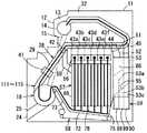
次に、図24に、硬貨収納カセット59の他の実施の形態を示す。硬貨収納カセット59は、硬貨収納部86の底面に硬貨を全量放出する硬貨放出口141を有し、この硬貨放出口141を閉塞する開閉板142を開閉可能に設ける。開閉板142は、搬送コンベヤ手段58から離れた一端側を支軸143で回動可能に支持され、搬送コンベヤ手段58に接近した他端側が上下に移動して硬貨放出口141を開閉可能としている。この開閉板142によって硬貨放出口94から硬貨収納部86内の硬貨を全量放出する全量放出手段97が構成されている。
【0146】
開閉板142の開放時には、開閉板142が搬送コンベヤ手段58上へ向けて斜め下方へ傾斜状に開放され、硬貨収納部86に収納していた補充硬貨を開閉板142の傾斜によって自重で硬貨放出口141から全量放出させ、搬送コンベヤ手段58に全量受収させることができる。
【0147】
搬送コンベヤ手段58の端部上には開閉板142の開放によって放出される硬貨を搬送コンベヤ手段58上に案内するガイド板144が配設されている。このガイド板144によって、硬貨収納カセット59から全量放出された全量放出硬貨CAを搬送コンベヤ手段58上へ送ることで、全量放出硬貨CAが開閉板142の上方への閉塞移動の障害にならないようにできる。
【0148】
なお、出金手段116は、硬貨通路装置28の途中または末端のどちらから操作者側へ硬貨を搬送する場合も含む。
【0149】
【発明の効果】
請求項1記載の循環式硬貨入出金機の回収処理装置によれば、第1の回収動作で、オーバーフロー硬貨を収納する硬貨収納カセットの硬貨収納部に収納された硬貨を全量放出し、全量放出した硬貨を搬送コンベヤ手段で全量受収するとともに精査回収搬送系へ送り、精査回収搬送系を通じて精査した後に硬貨収納カセットに回収し、また、第2の回収動作で、金種別硬貨収納投出装置から全量の硬貨を投出し、投出した全量の硬貨を搬送コンベヤ手段で受収するとともに精査回収搬送系へ送り、精査回収搬送系を通じて精査した後に硬貨収納カセットに回収するので、1つの硬貨収納カセットのみを使用して回収でき、そのため、構成を簡略化できてコストダウンでき、スペースを有効利用できるとともに、回収処理時間を短縮できる。
【0150】
請求項2記載の循環式硬貨入出金機の回収処理装置によれば、補充動作で、硬貨収納カセットの硬貨収納部の初期補充硬貨を全量放出し、全量放出した初期補充硬貨を補充搬送系を通じて金種別硬貨収納投出装置へ送り込むとともに金種別硬貨収納投出装置に送り込めない余剰補充硬貨を補充搬送系を通じて硬貨収納カセットの硬貨収納部へ回収させ、また、第1の回収動作で、オーバーフロー硬貨を収納する硬貨収納カセットの硬貨収納部に収納された硬貨を全量放出し、全量放出した硬貨を搬送コンベヤ手段で全量受収するとともに精査回収搬送系へ送り、精査回収搬送系を通じて精査した後に硬貨収納カセットに回収し、また、第2の回収動作で、金種別硬貨収納投出装置から全量の硬貨を投出し、投出した全量の硬貨を搬送コンベヤ手段で受収するとともに精査回収搬送系へ送り、精査回収搬送系を通じて精査した後に硬貨収納カセットに回収するので、1つの硬貨収納カセットのみを使用して補充とともに回収ができ、そのため、構成を簡略化できてコストダウンでき、スペースを有効利用できるとともに、回収処理時間を短縮できる。
【0151】
請求項3記載の循環式硬貨入出金機の回収処理装置によれば、請求項1または2記載の循環式硬貨入出金機の回収処理装置の効果に加えて、入金搬送系と精査回収搬送系とで硬貨貯留装置および硬貨通路装置を共用し、入金時および回収時に搬送コンベヤ手段に受収した硬貨を硬貨貯留装置へ送り込むため、構成を簡略化できてコストダウンでき、スペースを有効利用できる。
【0152】
請求項4記載の循環式硬貨入出金機の回収処理装置によれば、請求項2記載の循環式硬貨入出金機の回収処理装置の効果に加えて、入金搬送系と補充搬送系とで硬貨貯留装置および硬貨通路装置を共用し、入金時および補充時に搬送コンベヤ手段に受収した硬貨を硬貨貯留装置へ送り込むため、構成を簡略化できてコストダウンでき、スペースを有効利用できる。
【0153】
請求項5記載の循環式硬貨入出金機の回収処理装置によれば、請求項2記載の循環式硬貨入出金機の回収処理装置の効果に加えて、入金搬送系と補充搬送系と精査回収搬送系とで硬貨貯留装置および硬貨通路装置を共用し、入金時、補充時および精査時に搬送コンベヤ手段に受収した硬貨を硬貨貯留装置へ送り込むため、構成を簡略化できてコストダウンでき、スペースを有効利用できる。
【0154】
請求項6記載の循環式硬貨入出金機の回収処理装置によれば、請求項3ないし5いずれか記載の循環式硬貨入出金機の回収処理装置の効果に加えて、出金搬送系も硬貨貯留装置および硬貨通路装置を共用し、出金時に搬送コンベヤ手段に受収した硬貨を硬貨貯留装置へ送り込むため、構成を簡略化できてコストダウンでき、スペースを有効利用できる。
【0155】
請求項7記載の循環式硬貨入出金機の回収処理装置によれば、請求項1ないし6いずれか記載の循環式硬貨入出金機の回収処理装置の効果に加えて、硬貨収納カセットの硬貨収納部の硬貨を全量放出する全量放出手段が、硬貨収納部の硬貨放出口を開閉する開閉板の開放により、硬貨収納部の底部の傾斜底面によって硬貨を自重で硬貨放出口から放出させるため、例えばコンベヤなどを用いる場合に比べて構成を簡略化できてコストダウンでき、短時間で硬貨を全量放出できる。
【0156】
請求項8記載の循環式硬貨入出金機の回収処理装置によれば、請求項1ないし6いずれか記載の循環式硬貨入出金機の回収処理装置の効果に加えて、硬貨収納カセットの硬貨収納部の硬貨を全量放出する全量放出手段が、硬貨収納部の硬貨放出口を開閉する第1の開閉板および機体側の硬貨受入口を開閉する第2の開閉板の開放により、硬貨収納部の底部の傾斜底面によって硬貨を自重で硬貨放出口から放出させるため、例えばコンベヤなどを用いる場合に比べて構成を簡略化できてコストダウンでき、短時間で硬貨を全量放出でき、しかも、硬貨収納カセットが外されたときには、機体側の第2の開閉板を閉じることで、硬貨収納セットに関与しない処理をできる。
【0157】
請求項9記載の循環式硬貨入出金機の回収処理装置によれば、請求項1ないし8いずれか記載の循環式硬貨入出金機の回収処理装置の効果に加えて、硬貨収納カセットが、硬貨を全量放出可能とする硬貨収納部と別に、この硬貨収納部の収納量を超える硬貨を収納する硬貨非放出収納部を有するため、硬貨収納部の全量放出量を任意に設定でき、全量放出量を適正に設定して処理時間の短縮を図ることができる。
【図面の簡単な説明】
【図1】本発明の一実施の形態を示す循環式硬貨入出金機の概略を示す右側面図である。
【図2】同上図1のA−A矢視図である。
【図3】同上循環式硬貨入出金機の硬貨収納カセットを示し、(a)は右側面図、(b)は背面図、(c)は図3(b)のB−B矢視図である。
【図4】同上循環式硬貨入出金機の機体に対する硬貨収納カセットの脱着を説明する背面図である。
【図5】同上循環式硬貨入出金機の硬貨貯留装置および硬貨通路装置の右側面図である。
【図6】同上硬貨通路装置の種類別分岐部の部分の斜視図である。
【図7】同上循環式硬貨入出金機の搬送ベルト手段を示し、(a)は平面図、(b)は図7(a)のD−D矢視図である。
【図8】同上循環式硬貨入出金機の制御部による概略制御構成を示すブロック図である。
【図9】同上循環式硬貨入出金機の制御部による詳細制御構成を示すブロック図である。
【図10】同上循環式硬貨入出金機の初期補充処理を示す説明図である。
【図11】同上循環式硬貨入出金機の入金処理における一時保留までの入金送り込みを示す説明図である。
【図12】同上循環式硬貨入出金機の入金処理における入金オーバーフロー硬貨なしの場合の入金収納を示す説明図である。
【図13】同上循環式硬貨入出金機の入金処理における入金オーバーフロー硬貨ありの場合の入金収納を示す説明図である。
【図14】同上循環式硬貨入出金機の入金処理における入金返却を示す説明図である。
【図15】同上循環式硬貨入出金機の出金処理を示す説明図である。
【図16】同上循環式硬貨入出金機の途中補充処理を示す説明図である。
【図17】同上循環式硬貨入出金機の硬貨収納カセットの精査処理を示す説明図である。
【図18】同上循環式硬貨入出金機の金種別硬貨収納投出装置の精査処理を示す説明図である。
【図19】同上循環式硬貨入出金機の精査なし回収処理を示す説明図である。
【図20】同上循環式硬貨入出金機の精査あり回収処理における硬貨収納カセットからの第1の回収動作を示す説明図である。
【図21】同上循環式硬貨入出金機の精査あり回収処理における金種別硬貨収納投出装置からの第2の回収動作を示す説明図である。
【図22】同上循環式硬貨入出金機の異物排除処理を示す説明図である。
【図23】同上循環式硬貨入出金機の取り忘れ取り込み処理を示す説明図である。
【図24】本発明の他の実施の形態を示す硬貨収納カセットの断面図である。
【符号の説明】
11 機体
12 操作者側
18 硬貨貯留装置
19 硬貨繰出部としての回転円盤
28 硬貨通路装置
41 硬貨識別部
42,43a〜43f,44,45 種類別分岐部
56 入金一時保留装置
57 金種別硬貨収納投出装置
58 搬送コンベヤ手段
59 硬貨収納カセット
86 硬貨収納部
87 硬貨非放出収納部
94 硬貨放出口
95 傾斜底面
96 開閉板としての第1の開閉板
97 全量放出手段
102 硬貨受入口
103 第2の開閉板
111 補充搬送系
112 入金搬送系
113 出金搬送系
115 精査回収搬送系
116 出金手段
121 制御部
142 開閉板[0001]
BACKGROUND OF THE INVENTION
The present invention relates to a collection processing device for a circulating coin depositing and dispensing machine that deposits and dispenses coins.
[0002]
[Prior art]
Conventionally, for example, a coin depositing / withdrawing machine that is installed in an ATM used in a bank or the like and deposits and withdraws coins, in particular, accepts coins entered from the operator side, identifies the denomination, and by denomination identification Regular deposit coins are temporarily held in the deposit temporary hold device, and temporary hold coins that should be used for withdrawal when deposit is approved are thrown out from the deposit conveyance system and coin type coin storage and throw out device, which are sent to the denominated coin storage and dispensing device Scrutinizing and collecting the coins that are dispensed from the withdrawal and delivery system that transports the dispensed coins to the operator side, and all the coins that are thrown out from the denominated coin storage and dispensing device, and collects the coins that have been denominated There is a circulation type coin depositing and dispensing machine having a transport system.
[0003]
In the case of this circulation type coin depositing and dispensing machine, collection processing is performed through a scrutinizing and collecting transportation system. An overflow coin storage box that collects and stores coins that do not need to be replenished to the apparatus is also used for recovery processing. These replenishment coin storage boxes and overflow coin storage boxes each have a coin storage portion, and are provided with conveyor means for feeding coins in small amounts at the bottom of each coin storage portion (see, for example, Patent Document 1).
[0004]
Then, when collecting coins in the overflow coin storage box, if coins remain in the replenishment coin storage box, first, all the coins are sent out in small quantities by the conveyor means of the replenishment coin storage box. Store in the overflow coin storage box and empty the replenishment coin storage box. Next, while all the coins are sent out in small quantities by the conveyor means of the overflow coin storage box, the denomination and the number of coins are checked through the scrutiny collection system, and the scrutinized coins are sent to the replenishment coin storage box. This completes the collection of coins in the overflow coin storage box including the coins sent from the replenishment coin storage box to the overflow coin storage box.
[0005]
In addition, when collecting coins from the coin-type coin storage and dispensing device, if coins remain in the replenishment coin storage box, first, all the coins are sent out little by little by the conveyor means of the replenishment coin storage box, and then scrutinized and collected Store in the overflow coin storage box through the system and empty the replenishment coin storage box. Next, all the coins of the denomination type coin storage and dispensing device are thrown out one by one, and the coins and number of coins are checked through a scrutinizing and collecting transport system, and the coins after scrutiny are sent to the replenishment coin storage box. This completes the collection of coins in the denominated coin storage and dispensing apparatus.
[0006]
Thus, in the collection processing of the conventional circulation type coin depositing and dispensing machine, two storage boxes of the replenishment coin storage box and the overflow coin storage box are required.
[0007]
[Patent Document 1]
Japanese Patent Laid-Open No. 10-228553 (pages 6 to 7,
[0008]
[Problems to be solved by the invention]
When collecting with a conventional circulating coin depositing / dispensing machine, two storage boxes, a replenishment coin storage box and an overflow coin storage box, are required, resulting in an increase in cost, and a replenishment coin storage box in the machine. There is a problem that installation space for two storage boxes, that is, an overflow coin storage box, is required, and installation of other mechanisms is limited.
[0009]
Further, both when the coins in the overflow coin storage box are collected and when the coins of the denominated coin storage and dispensing apparatus are recovered, it is necessary to send out the coins that empty the replenishment coin storage box. Furthermore, in the case of collecting coins in the overflow coin storage box, all coins in the overflow coin storage box are then sent out little by little by the conveyor means of the overflow coin storage box, and all coins are replenished through the scrutiny collection system. It is necessary to send it to the storage box. In addition, in the case of collecting coins of a denominated coin storage and dispensing apparatus, it is necessary to throw out all the denominations of the denominated coin storage and dispensing apparatus one by one and send them to the replenishment coin storage box through a scrutinizing and collecting transport system. . Therefore, there is a problem in that it takes a long time for the collection process, and thus limits other processes such as a deposit process and a withdrawal process for the collection process that takes a long time.
[0010]
SUMMARY OF THE INVENTION The present invention has been made in view of this point. The collection processing device for a circulation type coin depositing and dispensing machine that simplifies the configuration, reduces cost, enables effective use of space, and shortens the collection processing time. The purpose is to provide.
[0011]
[Means for Solving the Problems]
The recovery processing device of the circulating coin depositing / dispensing machine according to claim 1 accepts the deposit coins input from the operator side, identifies the denomination, and temporarily stores the regular coins deposited by denomination in the deposit temporary storage device. Temporarily held coins that can be used for withdrawal at the time of deposit approval are sent to the coin-type coin storage and dispensing device, and the withdrawal coins that are dispensed from the coin-type coin storage and dispensing device are transported to the operator side. In the circulation type coin depositing and dispensing machine having a gold conveying system and a scrutinizing and collecting conveying system for identifying all coins thrown out from the coin storing and dispensing device according to denomination and collecting the coins denominated Opening and closing can be performed to receive deposit overflow coins that cannot be sent to the coin-type coin storage / disposal device among the regular deposit coins, and to collect the coins that are collected from the coin-type coin storage / disposal device, and to release all the received coins Hard A coin storage cassette having a coin storage portion having a discharge opening, in which all coins are discharged and the coin discharge opening is closed, and a coin storage cassette capable of receiving coins, and a total discharge from the coin storage portion of this coin storage cassette Of the received coins and all the coins thrown out from the denominated coin storage / dispensing device, the transport conveyor means for sending the received coins to the scrutinization collection transport system, and the coin storage in the transport conveyor means A first collection operation in which all the collected coins released from the coin storage unit of the cassette are scrutinized through a scrutinizing and collecting transport system and then collected into a coin storing cassette, and the coins are thrown out from the coin storing and dispensing device by denomination to the conveyor means. And a control unit that controls a second collecting operation for collecting the entire amount of coins through a scrutinizing and collecting transportation system and then collecting them into a coin storage cassette.
[0012]
In this configuration, in the first collecting operation, the entire amount of coins stored in the coin storage portion of the coin storage cassette storing the overflow coins is discharged, and all the discharged coins are received by the conveyer means and scrutinized and recovered. It is sent to the transport system, scrutinized through the scrutinizing and transporting system, collected in the coin storage cassette, and in the second recovery operation, all the coins are thrown out from the denominated coin storage and dispensing device. Is collected by the transport conveyor and sent to the scrutinizing and collecting transport system, and after being scrutinized through the scrutinizing and collecting transport system, it is collected in the coin storage cassette, so it can be recovered using only one coin storage cassette, and therefore the structure is simplified. As a result, the cost can be reduced, the space can be effectively used, and the collection processing time can be shortened.
[0013]
The recovery processing device of the circulation type coin depositing and dispensing machine according to claim 2 accepts the deposit coins inserted from the operator side and identifies the denomination, and the regular coins deposited by denomination are temporarily held in the deposit temporary holding device. Temporarily held coins that can be used for withdrawal at the time of deposit approval are deposited and transported to the coin storage and dispensing device, and replenished coins are received and denominated, and replenishable coins are branched into denominations The replenishment transport system that feeds into the type coin storage and dispensing device, the withdrawal transport system that transports the withdrawal coins dispensed from the money type coin storage and dispensing device to the operator side, and the coin type coin storage and dispensing device all throw out. In a circulating coin depositing and dispensing machine having a denomination identifying the coins to be dispensed, and a scrutinizing and collecting transportation system for collecting the coins identified by denomination, storing the initial supplementary coins loaded externally, Of which sent to coin storage and dispensing device A coin storage unit having an openable and closable coin discharge port that can receive unacceptable deposit overflow coins and receive coins that are collected from a coin storage and dispensing device according to denomination. A coin storage cassette that can receive coins to a coin storage part in which all the amount is released and the coin discharge port is closed, and the receipt of coins including the initial replenishment coins released from the coin storage part of the coin storage cassette, It is possible to receive all the coins thrown out from the coin storage and dispensing device according to denomination, and to convey the received coins to the scrutinizing and collecting transport system, and to the transport conveyor means from the coin storage section of the coin storage cassette Surplus replenishment coins that cannot be sent to the coin-type coin storage and dispensing device at the same time as the initial replenishment coins that have been released are sent to the coin-type coin storage and dispensing device through the replenishment transport system The replenishment operation for collecting the coin storage unit of the coin storage cassette through the replenishment transport system, and the transport conveyor means to scrutinize all the recovered coins released from the coin storage unit of the coin storage cassette through the scrutinization recovery transport system and then collect them in the coin storage cassette. The first collecting operation and the second collecting operation for collecting the entire amount of collected coins thrown from the denominated coin storage and dispensing device to the conveyor means through the scrutinizing and collecting transportation system and collecting them in the coin storage cassette are controlled. And a control unit.
[0014]
In this configuration, in the replenishment operation, all the initial replenishment coins in the coin storage unit of the coin storage cassette are discharged, all the released initial replenishment coins are sent to the denomination coin storage and dispensing device through the replenishment transport system, and denomination coins The surplus replenishment coins that cannot be sent to the storage and dispensing device are collected in the coin storage unit of the coin storage cassette through the replenishment transport system, and are stored in the coin storage unit of the coin storage cassette that stores the overflow coins in the first recovery operation. All the released coins are discharged, all of the released coins are received by the transport conveyor means, sent to the scrutinizing and collecting transport system, scrutinized through the scrutinizing and collecting transport system, and then collected into the coin storage cassette, and the second collecting operation Then, all the coins are thrown out from the coin-type coin storage and dispensing device, and all the coins that are thrown out are received by the conveyer means, and are also scrutinized and collected. Since it is collected in the coin storage cassette after being scrutinized through the scrutiny and collection transport system, it can be recovered with replenishment using only one coin storage cassette, so the configuration is simplified, cost reduction and effective use of space And the collection processing time can be shortened.
[0015]
The recovery processing device for the circulating coin depositing / dispensing machine according to claim 3 is the recovery processing device for the circulating coin depositing / dispensing machine according to claim 1 or 2, wherein the depositing and conveying system stores 1 A coin storage device having a coin feeding unit that feeds out coins one by one, a coin identifying unit that conveys coins fed one by one by a coin feeding unit of the coin storage device, and that identifies coins on the way of transport, and a type that branches coins by type It has a coin passage device having a branching section, and a deposit temporary holding device, the scrutinization and collection transportation system has a coin storage device and a coin passage device that share a part of the deposit transportation system, and the conveyor means is used for depositing The coins received at the time of collection are sent to the coin storage device.
[0016]
In this configuration, the deposit transport system and the scrutiny collection transport system share the coin storage device and the coin passage device, and the coins received by the transport conveyor means at the time of deposit and collection are sent to the coin storage device, so the configuration is simplified. It becomes possible to reduce costs and use space effectively.
[0017]
The recovery processing device of the circulating coin depositing / dispensing machine according to
[0018]
In this configuration, the coin storage device and the coin passage device are shared by the deposit transport system and the replenishment transport system, and the coins received by the transport conveyor means at the time of deposit and replenishment are sent to the coin storage device, thereby simplifying the configuration. As a result, cost reduction and effective use of space become possible.
[0019]
The collection processing device for the circulating coin depositing / dispensing machine according to claim 5 is the collection processing device for the circulating coin depositing / dispensing machine according to claim 2, wherein the depositing / conveying system stores and stores coins one by one. A coin storage device having a coin feeding portion to be fed, a coin identifying portion for conveying coins fed one by one by a coin feeding portion of the coin storage device, and for discriminating coins on the way of transport, and a branch portion for each type for branching the coins by type A replenishment conveyance system and a scrutinization collection conveyance system have a coin storage device and a coin passage device that share a part of the receipt conveyance system, Coins received at the time of deposit, replenishment and collection are sent to a coin storage device.
[0020]
In this configuration, the coin transfer device, the replenishment transfer system, and the scrutiny collection transport system share the coin storage device and the coin passage device, and the coin storage device receives the coins received by the transfer conveyor means at the time of deposit, replenishment, and scrutiny. Therefore, the configuration is simplified, and the cost can be reduced and the space can be effectively used.
[0021]
The recovery processing device for the circulating coin depositing / dispensing machine according to claim 6 is the recovery processing device for the circulating coin depositing / dispensing machine according to any one of claims 3 to 5, wherein the withdrawal transport system is a part of the deposit transport system. A coin storage device and a coin passage device that share the same, and also has a dispensing means for conveying coins from either the middle or the unfinished coin passage device to the operator side. The collected coins are sent to a coin storage device.
[0022]
In this configuration, the coin transfer system also shares the coin storage device and the coin passage device, and the coins received by the transfer conveyor means are sent to the coin storage device at the time of payment, so the configuration is simplified and the cost is reduced and the space is reduced. Can be used effectively.
[0023]
The recovery processing device for a circulating coin depositing / dispensing machine according to claim 7 is the recovery processing device for a circulating coin depositing / dispensing machine according to any one of claims 1 to 6, wherein the entire amount of coins in the coin storage portion of the coin storage cassette is discharged. The total amount discharging means includes an inclined bottom surface that is provided at the bottom of the coin storage portion and discharges coins from the coin discharge port under its own weight, and an opening / closing plate that opens and closes the coin discharge port.
[0024]
In this configuration, the total amount discharging means for discharging the total amount of coins in the coin storage portion of the coin storage cassette is formed by the inclined bottom surface of the coin storage portion by opening the opening / closing plate that opens and closes the coin discharge port of the coin storage portion. Is released from the coin discharge port by its own weight, for example, the configuration is simplified compared to the case of using a conveyor or the like, and the cost can be reduced and the entire amount of coins can be discharged in a short time.
[0025]
The collection processing device for a circulating coin depositing / dispensing machine according to claim 8 is the collection processing device for a circulating coin depositing / dispensing machine according to any one of claims 1 to 6, wherein a coin storage cassette is detachably mounted and the coin storage is performed. The machine has a machine body having a coin receiving port for receiving coins discharged from the coin storage part of the cassette, and is provided with a whole quantity discharge means for discharging all the coins of the coin storage part of the coin storage cassette mounted on the machine body. The means includes an inclined bottom surface that is provided at the bottom of the coin storage unit and releases coins by its own weight, a first opening / closing plate that opens and closes the coin discharge port, and a second opening / closing plate that opens and closes the coin receiving port on the machine body side. It is provided.
[0026]
And in this structure, the total amount discharge | release means which discharge | releases all the coins of the coin storage part of a coin storage cassette opens and closes the 1st opening-and-closing plate which opens and closes the coin discharge port of a coin storage part, and the coin receiving port by the side of a body. By opening the opening / closing plate 2, the coin is discharged from the coin discharge port by its own weight by the inclined bottom surface of the bottom of the coin storage part, so that the configuration is simplified compared with the case of using a conveyor, etc. In addition, when the coin storage cassette is removed, the second opening / closing plate on the machine body side is closed to enable processing not involved in the coin storage set.
[0027]
The collection processing device for a circulating coin depositing / dispensing machine according to claim 9 is the collection processing device for a circulating coin depositing / dispensing machine according to any one of claims 1 to 8, wherein the coin storage cassette is capable of discharging the entire amount of coins. In addition to the coin storage unit, a coin non-discharge storage unit that stores coins exceeding the storage amount of the coin storage unit is provided.
[0028]
And in this structure, since a coin storage cassette has a coin non-release storage part which stores the coin exceeding the storage amount of this coin storage part separately from the coin storage part which can discharge | release all the coins, The total amount released can be set arbitrarily, and the processing time can be shortened by setting the total amount released appropriately.
[0029]
DETAILED DESCRIPTION OF THE INVENTION
Hereinafter, embodiments of the present invention will be described with reference to the drawings.
[0030]
FIG. 1 to FIG. 23 show an embodiment of a collection processing apparatus for a circulating coin depositing and dispensing machine.
[0031]
In FIG. 1 and FIG. 2,
[0032]
A
[0033]
A plurality of
[0034]
The
[0035]
As shown in FIGS. 1 and 5, a coin passage device that accepts coins fed one by one from the
[0036]
The
[0037]
On the
[0038]
In the
[0039]
In the
[0040]
The
[0041]
Coin detection sensors (not shown) that detect coins conveyed in the
[0042]
As shown in FIG. 1, a
[0043]
Further, as shown in FIGS. 1 and 2, in the
[0044]
The deposit
[0045]
Further, as shown in FIGS. 1 and 2, the denomination coin storage and dispensing
[0046]
In each
[0047]
When the coins of the
[0048]
Further, as shown in FIGS. 1 and 2, the conveyor means 58 is arranged substantially horizontally at the bottom of the
[0049]
The
[0050]
The conveyor means 58 has an
[0051]
The receiving
[0052]
Also, as shown in FIGS. 1, 2 and 4, the
[0053]
As shown in FIG. 3, the
[0054]
Receiving
[0055]
A
[0056]
A
[0057]
As shown in FIG. 3, the
[0058]
On both sides of the
[0059]
1, 2, and 4, the lower side of the
[0060]
The
[0061]
Then, the circulating coin depositing / dispensing machine accepts the replenishment coins from the
[0062]
The withdrawal /
[0063]
FIG. 8 shows a schematic control configuration in which the
[0064]
The
[0065]
FIG. 9 shows a detailed control configuration in which the
[0066]
The
[0067]
At the time of replenishment, the transport conveyor means 58 is made to replenish the initial replenishment coins or intermediate replenishment coins released from the
[0068]
A function of collecting and storing deposit overflow coins temporarily held on the conveyor means 58 at the time of depositing into the
[0069]
A first scrutinizing operation for scrutinizing all the coins released from the
[0070]
A first collection operation for collecting the coins discharged from the
[0071]
Next, the operation of the present embodiment will be described.
[0072]
First, the initial replenishment process will be described with reference to FIG.
[0073]
The
[0074]
The clerk designates the initial replenishment mode at the
[0075]
By discharging all the initial replenishment coins stored in the
[0076]
By rotating the
[0077]
In the
[0078]
In the
[0079]
As a result of the identification by the
[0080]
The
[0081]
As a result of identification in the
[0082]
When the
[0083]
Next, the deposit process will be described with reference to FIGS.
[0084]
FIG. 11 shows a deposit sending operation at the time of deposit processing. When the operator commands depositing with the
[0085]
The deposited coins sent to the
[0086]
As a result of the identification by the
[0087]
The
[0088]
Reject coins determined to be inappropriate as a result of identification by the
[0089]
Then, if the
[0090]
FIG. 12 shows a deposit storing operation in the case where there is no deposit overflow coin when the operator performs a deposit approval operation using the
[0091]
FIG. 13 shows a deposit storing operation in the case where there is a deposit overflow coin in the case where the operator performs a deposit approval operation by the
[0092]
The deposit overflow coins temporarily held in the receiving
[0093]
When the
[0094]
The operations for storing the temporarily held coins from the deposit
[0095]
FIG. 14 shows a case where the operator performs an operation for rejecting payment by the
[0096]
The coins returned on the receiving
[0097]
Next, the withdrawal process will be described with reference to FIG.
[0098]
The storage cylinder corresponding to the withdrawal type of the coin-type coin storage /
[0099]
The withdrawal coins thrown onto the receiving
[0100]
As a result of the identification by the
[0101]
Rejected coins determined to be inappropriate are branched at the type-specific branching
[0102]
After the withdrawal coin corresponding to the withdrawal coin value has been sent to the
[0103]
Next, the midway replenishment process will be described with reference to FIG.
[0104]
When the amount of coins stored in the money type coin storage and dispensing
[0105]
By discharging all the replenishment coins stored in the
[0106]
The replenished coins received in the receiving
[0107]
As a result of the identification by the
[0108]
The
[0109]
As with the overflow coins, reject coins that are determined to be inappropriate as a result of identification by the
[0110]
When the
[0111]
In this replenishment process, by appropriately setting the coin storage amount of the
[0112]
Next, the examination process will be described with reference to FIGS.
[0113]
The clerk designates the scrutiny process at the
[0114]
FIG. 17 shows a first scrutiny operation for scrutinizing coins stored in the
[0115]
All the coins stored in the
[0116]
The coins received in the receiving
[0117]
Then, when the
[0118]
FIG. 18 shows a second scrutinizing operation for scrutinizing coins stored in the
[0119]
All the coins thrown on the receiving
[0120]
Then, when the
[0121]
Next, the collection process will be described with reference to FIGS.
[0122]
FIG. 19 shows a recovery process without scrutiny for recovering coins in the
[0123]
All the coins thrown on the receiving
[0124]
As a result of identification by the
[0125]
When the coins are not identified by the
[0126]
FIG. 20 shows a first collection operation in a collection process with inspection in which coins in the
[0127]
By releasing the entire amount of coins stored in the
[0128]
The coins received in the receiving
[0129]
When the
[0130]
FIG. 21 shows a second collection operation in the collection process with scrutiny. Subsequent to the first recovery operation, the second recovery operation in the recovery process with inspection is started. In this second collection operation, all coins are thrown out from the
[0131]
All the coins thrown on the receiving
[0132]
As a result of identification by the
[0133]
When the coins are no longer identified for a predetermined time by the
[0134]
After the first collection operation and the second collection operation, the
[0135]
Next, the foreign substance removal process will be described with reference to FIG.
[0136]
After depositing all the coins that can be paid out and received in the
[0137]
Next, the forgetting taking-in process will be described with reference to FIG.
[0138]
After deposit / return coin or reject coin is sent to the
[0139]
The forgotten coins sent to the
[0140]
When the
[0141]
As described above, in the collection processing device of the circulating coin depositing and dispensing machine, the first collection operation releases the entire amount of coins stored in the
[0142]
Furthermore, the
[0143]
Further, the total amount discharge means 97 for discharging the total amount of coins in the
[0144]
In addition, since the
[0145]
Next, FIG. 24 shows another embodiment of the
[0146]
When the opening / closing plate 142 is opened, the opening / closing plate 142 is inclined obliquely downward toward the transport conveyor means 58, and the replenishment coins stored in the
[0147]
A
[0148]
It should be noted that the dispensing means 116 includes a case where the coin is conveyed from either the middle or the end of the
[0149]
【The invention's effect】
According to the recovery processing device of the circulation type coin depositing and dispensing machine according to claim 1, all the coins stored in the coin storage portion of the coin storage cassette storing the overflow coins are discharged and discharged in the first recovery operation. All the received coins are received by the transport conveyor means and sent to the scrutinizing and collecting transport system. After being scrutinized through the scrutinizing and collecting transport system, the coins are collected into the coin storage cassette. All coins are thrown out, all the coins that are thrown out are received by the transport conveyor means, sent to the scrutinizing and collecting transport system, and after being scrutinized through the scrutinizing and collecting transport system, they are collected in the coin storing cassette, so only one coin storing cassette Therefore, the configuration can be simplified and the cost can be reduced, the space can be effectively used, and the recovery processing time can be shortened.
[0150]
According to the collection processing apparatus of the circulation type coin depositing and dispensing machine according to claim 2, in the replenishment operation, all the initial replenishment coins in the coin storage part of the coin storage cassette are discharged, and all the initial replenishment coins released are replenished through the replenishment transport system. The surplus replenishment coins that are sent to the denominated coin storage and dispensing device and that cannot be sent to the denominated coin storage and dispensing device are recovered to the coin storage unit of the coin storage cassette through the replenishment transport system, and overflow occurs in the first recovery operation. All the coins stored in the coin storage part of the coin storage cassette that stores the coins are discharged, all the discharged coins are received by the transport conveyor means, sent to the scrutinizing and collecting transport system, and then scrutinized through the scrutinizing and collecting transport system Collected in the storage cassette, and in the second collection operation, all the coins were thrown out from the denominated coin storage and dispensing device, and all the coins that were thrown out were conveyed on the conveyor. Since it is received at the stage and sent to the scrutinizing and collecting transport system, and scrutinized through the scrutinizing and collecting transport system, it is collected in the coin storage cassette, so it can be recovered with replenishment using only one coin storage cassette, thus simplifying the configuration The cost can be reduced, the space can be used effectively, and the collection processing time can be shortened.
[0151]
According to the collection processing device of the circulation type coin depositing / dispensing machine according to claim 3, in addition to the effect of the collection processing device of the circulation type coin depositing / dispensing machine according to claim 1 or 2, a deposit conveyance system and a scrutiny collection conveyance system. Since the coin storage device and the coin passage device are shared and the coins received by the transfer conveyor means are sent to the coin storage device at the time of depositing and collecting, the configuration can be simplified, the cost can be reduced, and the space can be used effectively.
[0152]
According to the recovery processing device of the circulation type coin depositing / dispensing machine according to
[0153]
According to the recovery processing device of the circulating coin depositing / dispensing machine according to claim 5, in addition to the effect of the recovery processing device of the circulating coin depositing / dispensing machine according to claim 2, a deposit transport system, a replenishment transport system, and a scrutiny collection The coin storage device and the coin passage device are shared with the transport system, and the coins received on the transport conveyor means are sent to the coin storage device at the time of deposit, replenishment, and scrutiny, so the configuration can be simplified and the cost can be reduced. Effective use.
[0154]
According to the recovery processing device of the circulating coin depositing and dispensing machine according to claim 6, in addition to the effect of the recovery processing device of the circulating coin depositing and dispensing machine according to any one of claims 3 to 5, Since the storage device and the coin passage device are shared and the coins received by the conveyor means are sent to the coin storage device at the time of withdrawal, the configuration can be simplified, the cost can be reduced, and the space can be used effectively.
[0155]
According to the recovery processing device of the circulation type coin depositing and dispensing machine according to claim 7, in addition to the effect of the recovery processing device of the circulation type coin depositing and dispensing machine according to any one of claims 1 to 6, the coin storage of the coin storage cassette In order to release the coin from the coin discharge port by its own weight by the inclined bottom surface of the bottom of the coin storage unit by opening the opening / closing plate that opens and closes the coin discharge port of the coin storage unit, for example, Compared to the case of using a conveyor or the like, the configuration can be simplified and the cost can be reduced, and the entire amount of coins can be discharged in a short time.
[0156]
According to the collection processing device of the circulation type coin depositing and dispensing machine according to claim 8, in addition to the effect of the collection processing device of the circulation type coin depositing and dispensing machine according to any one of claims 1 to 6, coin storage of the coin storage cassette The total amount discharging means for discharging the total amount of coins of the coin part opens the first opening and closing plate that opens and closes the coin discharge port of the coin storage unit and the second opening and closing plate that opens and closes the coin receiving port on the machine body side. Because coins are discharged from the coin outlet by the bottom of the bottom, the structure can be simplified and the cost can be reduced compared to the case of using a conveyor, etc., and the entire amount of coins can be discharged in a short time. When is removed, by closing the second opening / closing plate on the machine body side, processing that is not involved in the coin storage set can be performed.
[0157]
According to the recovery processing device of the circulating coin depositing / dispensing machine according to claim 9, in addition to the effect of the recovery processing device of the circulating coin depositing / dispensing machine according to any one of claims 1 to 8, the coin storage cassette includes a coin Since there is a coin non-discharge storage part that stores coins that exceed the storage capacity of this coin storage part separately from the coin storage part that enables the total amount release, the total amount discharge amount of the coin storage part can be set arbitrarily, The processing time can be shortened by appropriately setting.
[Brief description of the drawings]
FIG. 1 is a right side view showing an outline of a circulation type coin depositing and dispensing machine showing an embodiment of the present invention.
FIG. 2 is an AA arrow view of FIG.
FIG. 3 shows the coin storage cassette of the same circulating coin depositing and dispensing machine, where (a) is a right side view, (b) is a rear view, and (c) is a view along arrow BB in FIG. 3 (b). is there.
FIG. 4 is a rear view for explaining the attachment / detachment of the coin storage cassette to / from the machine body of the circulation type coin depositing / dispensing machine.
FIG. 5 is a right side view of the coin storage device and the coin passage device of the same circulating coin depositing and dispensing machine.
FIG. 6 is a perspective view of a part of a branch section according to type of the coin path device.
7A and 7B show transport belt means of the same circulating coin depositing and dispensing machine, where FIG. 7A is a plan view and FIG. 7B is a view taken along line DD in FIG.
FIG. 8 is a block diagram showing a schematic control configuration by a control unit of the same circulating coin depositing and dispensing machine.
FIG. 9 is a block diagram showing a detailed control configuration by a control unit of the same circulating coin depositing and dispensing machine.
FIG. 10 is an explanatory view showing an initial replenishment process of the circulation type coin depositing and dispensing machine.
FIG. 11 is an explanatory view showing the deposit sending up to the temporary hold in the deposit process of the same circulating coin depositing and dispensing machine.
FIG. 12 is an explanatory view showing the deposit storage when there is no deposit overflow coin in the deposit process of the same circulating coin depositing and dispensing machine.
FIG. 13 is an explanatory view showing deposit storage in the case where there is a deposit overflow coin in the deposit process of the circulation type coin depositing and dispensing machine.
FIG. 14 is an explanatory view showing the deposit return in the deposit process of the same circulating coin depositing and dispensing machine.
FIG. 15 is an explanatory view showing a dispensing process of the circulation type coin depositing and dispensing machine.
FIG. 16 is an explanatory view showing midway replenishment processing of the same circulating coin depositing and dispensing machine.
FIG. 17 is an explanatory view showing a scrutinizing process of the coin storage cassette of the circulation type coin depositing and dispensing machine.
FIG. 18 is an explanatory view showing a scrutinization process of the coin storing and dispensing apparatus according to denomination of the same circulating coin depositing and dispensing machine.
FIG. 19 is an explanatory view showing a recovery process without scrutiny of the same circulating coin depositing and dispensing machine.
FIG. 20 is an explanatory view showing a first recovery operation from a coin storage cassette in a recovery process with scrutiny by the circulation type coin depositing / dispensing machine.
FIG. 21 is an explanatory view showing a second recovery operation from the denominated coin storage / dispensing device in the recovery processing with scrutiny of the circulation type coin depositing / dispensing machine.
FIG. 22 is an explanatory view showing foreign matter removal processing of the same circulating coin depositing and dispensing machine.
FIG. 23 is an explanatory diagram showing a forgetting taking-in process of the circulation type coin depositing and dispensing machine.
FIG. 24 is a cross-sectional view of a coin storage cassette showing another embodiment of the present invention.
[Explanation of symbols]
11 Airframe
12 Operator side
18 Coin storage device
19 Rotating disc as a coin feeding part
28 Coin passage device
41 Coin identification part
42, 43a to 43f, 44, 45 Branches by type
56 Temporary deposit device
57 Coin storage and dispensing device by type
58 Conveyor means
59 Coin storage cassette
86 Coin storage
87 Coin non-release storage
94 coin outlet
95 Inclined bottom
96 First open / close plate as open / close plate
97 Total release means
102 coin entry
103 Second opening / closing plate
111 Replenishment transport system
112 Deposit transfer system
113 Withdrawal transportation system
115 scrutiny collection transport system
116 means of withdrawal
121 Control unit
142 Opening and closing plate
Claims (9)
Translated fromJapaneseこの硬貨収納カセットの硬貨収納部から全量放出された硬貨の受収、および金種別硬貨収納投出装置から投出された全量の硬貨の受収が可能で、受収した硬貨を精査回収搬送系へ送る搬送コンベヤ手段と、
この搬送コンベヤ手段に硬貨収納カセットの硬貨収納部から全量放出された回収硬貨を精査回収搬送系を通じて精査した後に硬貨収納カセットへ回収させる第1の回収動作、および搬送コンベヤ手段に金種別硬貨収納投出装置から投出された全量の硬貨を精査回収搬送系を通じて精査した後に硬貨収納カセットへ回収させる第2の回収動作を制御する制御部と
を具備していることを特徴とする循環式硬貨入出金機の回収処理装置。Receiving coins entered from the operator side and identifying the denomination, the regular coins received by denomination are temporarily held in the deposit temporary holding device, and the temporarily held coins that can be used for withdrawal at the time of deposit approval are the denomination type A deposit transfer system for feeding into the storage and dispensing device, a withdrawal transport system for transporting the withdrawal coins dispensed from the denominated coin storage and dispensing device to the operator side, and a denominated coin storage and dispensing device are all thrown out. In a circulation type coin depositing and dispensing machine having a coin type identification and a scrutinizing and collecting transportation system for collecting the coins identified by the denomination, it is not possible to send to the coin type coin storage and dispensing device among the regular coins deposited when the deposit is approved It has a coin storage part that has an openable and closable coin outlet that collects incoming coins and collects coins that are collected from the coin-type coin storage and dispensing device, and discharges all the received coins. A coin storage cassette to allow deferred coins to the coin storing unit coin outlet is closed Te,
Transport of all coins released from the coin storage part of this coin storage cassette and receipt of all coins thrown out from the coin storage and dispensing device by denomination, and transporting the received coins to the scrutinizing and collecting transport system Conveyor means;
A first collection operation in which all the collected coins discharged from the coin storage unit of the coin storage cassette are scrutinized through the scrutiny collection and transport system and then collected into the coin storage cassette is collected by the transport conveyor means, and the coin type coin storage and investment is transported to the transport conveyor means. A circulation type coin insertion / removal comprising a control unit for controlling a second collection operation for collecting all coins thrown out from the dispensing device through a scrutinizing and collecting conveyance system and then collecting them into a coin storage cassette. A collection machine for gold machines.
外部で装填される初期補充硬貨の収納、入金承認時に入金正規硬貨のうち金種別硬貨収納投出装置へ送り込めない入金オーバーフロー硬貨の受収、および金種別硬貨収納投出装置から投出される回収硬貨の受収が可能で、受収した硬貨を全量放出する開閉可能な硬貨放出口を有する硬貨収納部を備え、硬貨が全量放出されて硬貨放出口が閉塞された硬貨収納部に対し硬貨を受収可能とする硬貨収納カセットと、
この硬貨収納カセットの硬貨収納部から全量放出された初期補充硬貨を含む硬貨の受収、および金種別硬貨収納投出装置から投出された全量の硬貨の受収が可能で、受収した硬貨を精査回収搬送系へ送る搬送コンベヤ手段と、
この搬送コンベヤ手段に硬貨収納カセットの硬貨収納部から全量放出された初期補充硬貨を補充搬送系を通じて金種別硬貨収納投出装置へ送り込むとともに金種別硬貨収納投出装置に送り込めない余剰補充硬貨を補充搬送系を通じて硬貨収納カセットの硬貨収納部へ回収させる補充動作、搬送コンベヤ手段に硬貨収納カセットの硬貨収納部から全量放出された回収硬貨を精査回収搬送系を通じて精査した後に硬貨収納カセットへ回収させる第1の回収動作、および搬送コンベヤ手段に金種別硬貨収納投出装置から投出された全量の回収硬貨を精査回収搬送系を通じて精査した後に硬貨収納カセットへ回収させる第2の回収動作を制御する制御部と
を具備していることを特徴とする循環式硬貨入出金機の回収処理装置。Receiving coins entered from the operator side and identifying the denomination, the regular coins deposited by denomination are temporarily held in the deposit temporary holding device, and the temporarily held coins that can be used for withdrawal at the time of deposit approval are the denomination type A deposit transfer system that feeds into the storage and dispensing device, a replenishment coin that accepts replenishment coins, identifies the denomination, branches a replenishable coin into a denomination and sends it to the denomination coin storage and dispensing device, and a denomination coin storage Identify the denominations of the coins that are dispensed from the dispensing device to the operator side, and all the coins that are dispensed from the denominated coin storage and dispensing device, and collect the denominated coins In a circulating coin depositing and dispensing machine having a scrutinizing and collecting transportation system,
Storage of initial replenishment coins loaded externally, receipt of deposit overflow coins that cannot be sent to the denomination type coin storage / disposal device when the deposit is approved, and recovered coins thrown from the denomination type coin storage / disposal device A coin storage part having an openable and closable coin discharge port that discharges all the received coins, and the coins can be received in the coin storage part in which all the coins are discharged and the coin discharge port is closed A coin storage cassette,
It is possible to receive coins including the initial replenishment coins released from the coin storage part of this coin storage cassette, and to receive all the coins thrown out from the denominated coin storage and dispensing device. Conveying conveyor means for sending to the conveying system;
The initial replenishment coins released from the coin storage unit of the coin storage cassette are all fed to the conveyor conveyor means through the replenishment transport system to the denominated coin storage and dispensing device, and surplus replenishment coins that cannot be sent to the denominated coin storage and dispensing device. The replenishment operation for collecting the coin storage unit of the coin storage cassette through the replenishment transport system, and the transport conveyor means to scrutinize all the recovered coins released from the coin storage unit of the coin storage cassette through the scrutinization recovery transport system and then collect them in the coin storage cassette. The first collecting operation and the second collecting operation for collecting the entire amount of collected coins thrown from the denominated coin storage and dispensing device to the conveyor means through the scrutinizing and collecting transportation system and collecting them in the coin storage cassette are controlled. A recovery processing device for a circulating coin depositing and dispensing machine, comprising: a control unit.
精査回収搬送系は、入金搬送系の一部を共用する硬貨貯留装置および硬貨通路装置を有し、
搬送コンベヤ手段は、入金時および回収時に受収した硬貨を硬貨貯留装置へ送り込む
ことを特徴とする請求項1または2記載の循環式硬貨入出金機の回収処理装置。The deposit transfer system has a coin storage unit having a coin supply unit that stores and stores the coins one by one, conveys coins that are fed out one by one by the coin supply unit of the coin storage unit, and transfers coins in the middle of conveyance. A coin passage device having a coin discriminating unit for identifying and a type-specific branching unit for branching coins by type, and a deposit temporary holding device;
The scrutiny collection transport system has a coin storage device and a coin passage device that share part of the deposit transport system,
3. The collection processing device for a circulating coin depositing and dispensing machine according to claim 1, wherein the conveyor means sends coins received at the time of depositing and collecting to a coin storage device.
補充搬送系は、入金搬送系の一部を共用する硬貨貯留装置および硬貨通路装置を有し、
搬送コンベヤ手段は、入金時および補充時に受収した硬貨を硬貨貯留装置へ送り込む
ことを特徴とする請求項2記載の循環式硬貨入出金機の回収処理装置。The deposit conveyance system stores a coin and has a coin storage device that has a coin supply unit that supplies the stored coins one by one, and conveys coins that are supplied one by one by a coin supply unit of the coin storage device, and is in the process of being transferred. A coin passage device having a coin identifying unit for identifying the type and a branch unit for each type for branching the coins by type, and a deposit temporary holding device,
The replenishment conveyance system has a coin storage device and a coin passage device that share a part of the deposit conveyance system,
3. The recovery processing apparatus for a circulating coin depositing and dispensing machine according to claim 2, wherein the conveyor means feeds the coins received at the time of depositing and replenishing to a coin storage device.
補充搬送系および精査回収搬送系は、入金搬送系の一部を共用する硬貨貯留装置および硬貨通路装置を有し、
搬送コンベヤ手段は、入金時、補充時および回収時に受収した硬貨を硬貨貯留装置へ送り込む
ことを特徴とする請求項2記載の循環式硬貨入出金機の回収処理装置。The deposit transfer system has a coin storage unit having a coin supply unit that stores and stores the coins one by one, conveys coins that are fed out one by one by the coin supply unit of the coin storage unit, and transfers coins in the middle of conveyance. A coin passage device having a coin discriminating unit for identifying and a type-specific branching unit for branching coins by type, and a deposit temporary holding device;
The replenishment transport system and the scrutiny collection transport system have a coin storage device and a coin passage device that share a part of the deposit transport system,
3. The recovery processing apparatus for a circulating coin depositing and dispensing machine according to claim 2, wherein the conveyor means feeds coins received at the time of depositing, replenishing and collecting to a coin storage device.
搬送コンベヤ手段は、出金時に受収した出金硬貨を硬貨貯留装置へ送り込む
ことを特徴とする請求項3ないし5いずれか記載の循環式硬貨入出金機の回収処理装置。The withdrawal transport system has a coin storage device and a coin passage device that share a part of the deposit transportation system, and withdraws means for transporting coins from the middle of the coin passage device to the operator side. Have
6. The recovery processing apparatus for a circulating coin depositing / dispensing machine according to claim 3, wherein the conveyor means feeds the withdrawal coins received at the time of withdrawal to the coin storage device.
この機体に装着された硬貨収納カセットの硬貨収納部の硬貨を全量放出する全量放出手段を備え、この全量放出手段は、硬貨収納部の底部に設けられ硬貨を自重で放出する傾斜底面と、硬貨放出口を開閉する第1の開閉板と、機体側の硬貨受入口を開閉する第2の開閉板とを備えた
ことを特徴とする請求項1ないし6いずれか記載の循環式硬貨入出金機の回収処理装置。A coin storage cassette is detachably mounted, and includes a machine body having a coin receiving port for receiving coins discharged from the coin storage portion of the coin storage cassette.
A total amount discharging means for discharging all the coins of the coin storage portion of the coin storage cassette mounted on the machine body, the total amount discharging means being provided at the bottom of the coin storage portion, an inclined bottom surface for discharging coins by its own weight, and a coin The circulation type coin depositing and dispensing machine according to any one of claims 1 to 6, further comprising a first opening / closing plate for opening / closing the discharge port and a second opening / closing plate for opening / closing the coin receiving port on the machine body side. Recovery processing equipment.
ことを特徴とする請求項1ないし8いずれか記載の循環式硬貨入出金機の回収処理装置。9. The coin storage cassette includes a coin non-discharge storage section that stores coins that exceed the storage capacity of the coin storage section, in addition to the coin storage section that allows the entire amount of coins to be discharged. The collection processing apparatus of the described circulation type coin depositing and dispensing machine.
Priority Applications (1)
| Application Number | Priority Date | Filing Date | Title |
|---|---|---|---|
| JP2003121798AJP4284101B2 (en) | 2003-04-25 | 2003-04-25 | Recycling processing equipment for circulating coin depositing and dispensing machine |
Applications Claiming Priority (1)
| Application Number | Priority Date | Filing Date | Title |
|---|---|---|---|
| JP2003121798AJP4284101B2 (en) | 2003-04-25 | 2003-04-25 | Recycling processing equipment for circulating coin depositing and dispensing machine |
Publications (2)
| Publication Number | Publication Date |
|---|---|
| JP2004326542A JP2004326542A (en) | 2004-11-18 |
| JP4284101B2true JP4284101B2 (en) | 2009-06-24 |
Family
ID=33500242
Family Applications (1)
| Application Number | Title | Priority Date | Filing Date |
|---|---|---|---|
| JP2003121798AExpired - Fee RelatedJP4284101B2 (en) | 2003-04-25 | 2003-04-25 | Recycling processing equipment for circulating coin depositing and dispensing machine |
Country Status (1)
| Country | Link |
|---|---|
| JP (1) | JP4284101B2 (en) |
Families Citing this family (3)
| Publication number | Priority date | Publication date | Assignee | Title |
|---|---|---|---|---|
| JP2006338104A (en)* | 2005-05-31 | 2006-12-14 | Hitachi Omron Terminal Solutions Corp | Coin processing equipment |
| JP4960690B2 (en)* | 2006-12-08 | 2012-06-27 | グローリー株式会社 | Coin deposit and withdrawal machine |
| JP2023037307A (en) | 2021-09-03 | 2023-03-15 | グローリー株式会社 | Currency processing device and currency processing method |
- 2003
- 2003-04-25JPJP2003121798Apatent/JP4284101B2/ennot_activeExpired - Fee Related
Also Published As
| Publication number | Publication date |
|---|---|
| JP2004326542A (en) | 2004-11-18 |
Similar Documents
| Publication | Publication Date | Title |
|---|---|---|
| JP4956580B2 (en) | Circulating coin deposit and withdrawal machine | |
| JP4336519B2 (en) | Circulating coin deposit and withdrawal machine | |
| JP4284100B2 (en) | Scrutinization processing equipment for circulating coin depositing and dispensing machine | |
| JP3673052B2 (en) | Trading unit of coin depositing and dispensing machine | |
| JP4284101B2 (en) | Recycling processing equipment for circulating coin depositing and dispensing machine | |
| JP2004334597A (en) | Circulating coin depositing and dispensing machine | |
| JP4764019B2 (en) | Circulating coin deposit and withdrawal machine | |
| JP2004341789A (en) | Circulation type coin depositing/dispensing machine | |
| JP4280106B2 (en) | Circulating coin deposit and withdrawal machine | |
| JP4815131B2 (en) | Coin deposit device | |
| JP4234855B2 (en) | Coin handling machine | |
| JPH10228553A (en) | Coin receiving and paying machine | |
| JP4764020B2 (en) | Coin processing apparatus and coin processing method | |
| JP4598542B2 (en) | Circulating coin deposit and withdrawal machine | |
| JP4598544B2 (en) | Circulating coin deposit and withdrawal machine | |
| JPH10228556A (en) | Coin carrier device and residual coin or the like carrier device of coin receiving processing machine | |
| JP3867753B2 (en) | Coin processing equipment | |
| JP3214842B2 (en) | Coin dispensing machine | |
| JP3214843B2 (en) | Circulating coin depositing and dispensing machine | |
| JP3227434B2 (en) | Coin depositing machine | |
| JP2003157464A (en) | Coin processing machine | |
| JP3227435B2 (en) | Coin dispensing machine | |
| JP3774289B2 (en) | Coin deposit and withdrawal machine | |
| JP3227436B2 (en) | Coin dispensing machine | |
| JP4598543B2 (en) | Circulating coin deposit and withdrawal machine |
Legal Events
| Date | Code | Title | Description |
|---|---|---|---|
| A621 | Written request for application examination | Free format text:JAPANESE INTERMEDIATE CODE: A621 Effective date:20060220 | |
| A977 | Report on retrieval | Free format text:JAPANESE INTERMEDIATE CODE: A971007 Effective date:20081118 | |
| TRDD | Decision of grant or rejection written | ||
| A01 | Written decision to grant a patent or to grant a registration (utility model) | Free format text:JAPANESE INTERMEDIATE CODE: A01 Effective date:20090311 | |
| A01 | Written decision to grant a patent or to grant a registration (utility model) | Free format text:JAPANESE INTERMEDIATE CODE: A01 | |
| A61 | First payment of annual fees (during grant procedure) | Free format text:JAPANESE INTERMEDIATE CODE: A61 Effective date:20090323 | |
| R150 | Certificate of patent or registration of utility model | Free format text:JAPANESE INTERMEDIATE CODE: R150 | |
| FPAY | Renewal fee payment (event date is renewal date of database) | Free format text:PAYMENT UNTIL: 20120327 Year of fee payment:3 | |
| FPAY | Renewal fee payment (event date is renewal date of database) | Free format text:PAYMENT UNTIL: 20120327 Year of fee payment:3 | |
| FPAY | Renewal fee payment (event date is renewal date of database) | Free format text:PAYMENT UNTIL: 20130327 Year of fee payment:4 | |
| FPAY | Renewal fee payment (event date is renewal date of database) | Free format text:PAYMENT UNTIL: 20130327 Year of fee payment:4 | |
| FPAY | Renewal fee payment (event date is renewal date of database) | Free format text:PAYMENT UNTIL: 20140327 Year of fee payment:5 | |
| LAPS | Cancellation because of no payment of annual fees |