JP4284003B2 - Video signal output device - Google Patents
Video signal output deviceDownload PDFInfo
- Publication number
- JP4284003B2 JP4284003B2JP2001041001AJP2001041001AJP4284003B2JP 4284003 B2JP4284003 B2JP 4284003B2JP 2001041001 AJP2001041001 AJP 2001041001AJP 2001041001 AJP2001041001 AJP 2001041001AJP 4284003 B2JP4284003 B2JP 4284003B2
- Authority
- JP
- Japan
- Prior art keywords
- signal
- video signal
- progressive
- video
- frames
- Prior art date
- Legal status (The legal status is an assumption and is not a legal conclusion. Google has not performed a legal analysis and makes no representation as to the accuracy of the status listed.)
- Expired - Lifetime
Links
- 230000000750progressive effectEffects0.000claimsdescription56
- 230000007274generation of a signal involved in cell-cell signalingEffects0.000claimsdescription27
- 238000001514detection methodMethods0.000claimsdescription11
- 238000006243chemical reactionMethods0.000claimsdescription6
- 238000003780insertionMethods0.000claimsdescription3
- 230000037431insertionEffects0.000claimsdescription3
- 238000010586diagramMethods0.000description3
- 238000000034methodMethods0.000description2
- 230000006835compressionEffects0.000description1
- 238000007906compressionMethods0.000description1
- 230000000694effectsEffects0.000description1
- 230000008929regenerationEffects0.000description1
- 238000011069regeneration methodMethods0.000description1
Images

Landscapes
- Television Signal Processing For Recording (AREA)
- Television Systems (AREA)
Description
Translated fromJapanese【0001】
本発明は、DVD(Digital Versatile Disc)プレーヤなど映像信号を出力する映像信号出力装置に関し、特にプログレッシブ信号を出力することができる映像信号出力装置に関する。
【発明の属する技術分野】
【0002】
【従来の技術】
映画フィルムなどの映画素材から作成されたDVDビデオソフトには、MPEGエンコード時の圧縮率を高めるため、映画フィルムと同じ24コマ/秒の静止画からなる映像信号が記録され、更にこの24コマ/秒の静止画をインターレースのビデオ信号(60フィールド/秒)に変換するためのFFRF(First Field Repeat Flag)信号が記録されている。従って、映画素材から作成されたDVDビデオソフトを再生する場合、このFFRF信号に基づき、ディスク再生部内のメモリに蓄積された各静止画データを順次3回、2回、3回、2回、・・・と繰り返し読み出せば完全なプログレッシブ信号を容易に生成することが出来る。
【0003】
一方、ビデオテープレコーダなどのビデオ素材から作成されたDVDビデオソフトには、インターレース処理された映像信号が30コマ/秒で記録されており、この場合、プログレッシブ信号生成回路は、映像信号本来がインターレース処理されているため、映像信号の動き検出を正確に行うことができる大規模な信号処理回路が必要とされる。
【0004】
【発明が解決しようとする課題】
しかしながら、ローコストなDVDプレーヤにおいては、コスト的な面から映像信号の動き検出を正確に行うことができる高価なプログレッシブ信号生成回路を搭載することができず、簡易的なフィールド内補間方式のプログレッシブ信号生成回路の搭載に留まる。このため、係るDVDプレーヤによれば、ビデオ素材から作成されたDVDビデオソフトを再生した場合に出力するプログレッシブ信号の品質が悪く、プログレッシブ方式のデレビ受像機に接続するとその表示画像にフリッカ等が発生してしまうという問題があった。
【0005】
一方、プログレッシブ方式のテレビ受像機は、高額商品であるが故に、その内部に映像信号の動き検出を正確に行い、高品位なプログレッシブ信号を生成することができるインターレース/プログレッシブ変換器(以下、I/P変換器という)を備える。しかし、テレビ受像機側のI/P変換器は、いかに高品位なプログレッシブ信号を生成できるといっても、その入力映像信号にはFFRF信号が含まれていないため、DVDプレーヤがFFRF信号に基づき生成した完全なプログレッシブ信号より品質が劣るという欠点があった。
【0006】
本発明は、上記課題に鑑み成されたものであり、映像信号のコマ数に拘わらず、プログレッシブ方式のテレビ受像機上で常に最高の画質を得ることができる映像信号出力装置を提供することにある。
【0007】
【課題を解決するための手段】
上記課題を解決するため請求項1に記載の発明は、映像信号からインターレース信号を生成するインターレース信号生成回路と、映像信号からプログレッシブ信号を生成するプログレッシブ信号生成回路と、映像信号が24コマ/秒と30コマ/秒の何れであるかを検出する検出回路と、検出回路の出力に基づき映像信号が24コマ/秒である時、プログレッシブ信号を選択して出力し、また映像信号が30コマ/秒である時、インターレース信号を選択して出力する切替回路とを備えることを特徴とする。
【0008】
また、請求項2に記載の発明に係る映像信号出力装置は、請求項1に記載の映像信号出力装置において、映像信号は24コマ/秒である時、2−3変換のフィールド挿入点を示すFFRF信号を含み、検出回路は当該FFRF信号の有無を見て、映像信号が24コマ/秒と30コマ/秒の何れであるかを検出することを特徴とする。
【0009】
また、請求項3に記載の発明に係る映像信号出力装置は、請求項2に記載の映像信号出力装置において、プログレッシブ信号生成回路はFFRF信号に基づいて、プログレッシブ信号を生成することを特徴とする。
【0010】
【発明の実施の形態】
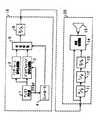
次に、本発明の第1実施形態による映像信号出力装置10について説明する。図1は、本発明の第1実施形形態による映像信号出力装置10と、プログレッシブ信号の入力が可能なテレビ受像機20の要部回路ブロック図である。図1を用いて本実施形態の映像信号出力装置10の回路構成を説明する。尚、テレビ受像機の要部回路構成についても併せて説明する。
【0011】
映像信号出力装置10は、DVDビデオプレーヤを構成しており、DVDビデオソフト(図示しない)を再生するディスク再生部1と、再生された映像信号からインターレース信号を生成するインターレース信号生成回路2と、再生された映像信号からプログレッシブ信号を生成するプログレッシブ信号生成回路3と、コントローラ4と、コントローラ4の制御信号に基づきインターレース信号生成回路2の出力信号とプログレッシブ信号生成回路3の出力信号を切り換える切替回路5と、当該切替回路5から出力されるデジタル信号をアナログ信号に変換するD/A変換器6とで構成されている。尚、コントローラ4は、再生された映像信号からFFRF(First Field Repeat Flag)信号を検出する検出回路を担い、当該検出回路の検出結果に基づき切替回路5を制御するように構成されている。なお、FFRF信号の詳細については、ISO/IEC13818-2 MPEG 2スタンダードの記載を参照されたい。
【0012】
一方、映像信号出力装置10に接続されるテレビ受像機20は、入力映像信号をデジタル信号に変換するA/D変換器11と、当該デジタル化された入力映像信号をプログレッシブ信号に変換する高性能なI/P変換器12と、このプログレッシブ信号をアナログ信号に戻すD/A変換器13と、入力映像信号がプログレッシブ信号である場合、それを直接処理し、入力映像信号がインターレース信号である場合、上述したA/D変換器11、I/P変換器12およびD/A変換器13により変換されたプログレッシブ信号を自動的に選択処理する映像処理回路14と、映像処理回路14から出力された表示信号を表示するブラウン管からなる表示装置15と、から構成された所謂プログレッシブテレビである。
【0013】
次に第1実施形態の映像信号出力装置10の動作を説明する。
映像信号出力装置10は、使用者によりDVDビデオソフトの再生操作が行われると、ディスク再生部1でDVDビデオソフトを再生する。コントローラ4は、ディスク再生部1から再生された映像信号に2−3変換のフィールド挿入点を示すFFRF信号が含まれていない場合、装着されたDVDビデオソフトがビデオ素材から作成された30コマ/秒のDVDビデオソフトであると判断し、切替回路5をインターレース信号生成回路2側に切り換える。インターレース信号生成回路2は、ディスク再生部1から供給される再生映像信号に基づきインターレース信号を生成して出力する。映像信号出力装置10は、切替回路5により生成されたインターレース信号をD/A変換器6によりアナログ信号に変換して出力する。
【0014】
また、コントローラ4は、ディスク再生部1から再生された映像信号にFFRF信号が含まれている場合、装着されたDVDビデオソフトが映画素材から作成された24コマ/秒のDVDビデオソフトであると判断し、切替回路5をプログレッシブ信号生成回路3側に切り換える。映像信号出力装置10は、切替回路5から出力されたプログレッシブ信号をD/A変換器6によりアナログ信号に変換して出力する。
【0015】
この第1実施形態は、ディスク再生部1内に設けられた映像信号出力回路(図示しない)とインターレース信号生成回路2とプログレッシブ信号生成回路3とを、一つのLSI上に構成する場合に好適であり、プログレッシブ信号がインターレース信号生成回路2を介することなく生成されることからその高品位化が図れる。
【0016】
一方、テレビ受像機20では、映像信号出力装置10から供給された映像信号がプログレッシブ信号の場合、それを映像処理回路14により直接信号処理して表示装置15に表示する。
【0017】
また、テレビ受像機20は、映像信号出力装置10から供給された映像信号がインターレース信号の場合、入力映像信号をA/D変換器11でデジタル信号に変換した後、I/P変換器12によりプログレッシブ信号に変換する。なお、I/P変換器12は、映像信号出力装置10側から供給される奇数フィールドの画像データと偶数フィールドの画像データとを図示しないメモリに取り込んで、フィールド毎の画像データの隣接する画素間の差分に基づいて画像の動き検出を行う。そして、I/P変換器12は、この動き検出の結果に基づいてフィールド間補間を行い、30コマ/秒の画像データを60コマ/秒のプログレッシブ信号に変換するものである。このI/P変換器12から出力されたプログレッシブ信号はD/A変換器13によりアナログ信号に変換される。入力映像信号がインターレース信号であるため、映像処理回路14はD/A変換器13から出力されたプログレッシブ信号を選択、信号処理して表示装置15に表示する。
【0018】
上述したように第1実施形態の映像信号出力装置10によれば、ディスク再生部1から供給される映像信号が30コマ/秒の場合、テレビ受像機20側により高精度のI/P変換が行われるよう、インターレース信号からなる映像信号を出力する。一方、ディスク再生部1から供給される映像信号が24コマ/秒の場合は、ディスクから得られたFFRF信号を用いてその内部により完全なI/P変換を行って、プログレッシブ信号からなる映像信号を出力する。よって、テレビ受像機20上では常に最高の画質を得ることが可能となる。
【0019】
次に、本発明の第2実施形態における映像信号出力装置30について図2を用いて説明する。なお、第2実施形態の映像信号出力装置30は、図2に示すようにプログレッシブ信号生成回路3がインターレース信号生成回路2で生成されたインターレース信号に基づきプログレッシブ信号を生成する点が、第1実施形態の映像信号出力装置10と相違する。その他の構成については、上述した第1実施形態の場合と同様であるため、詳細な説明を省略する。
【0020】
映像信号出力装置30は、使用者によりDVDビデオソフトの再生操作が行われると、ディスク再生部1でDVDビデオソフトを再生する。コントローラ4は、供給される映像信号にFFRF信号が含まれていない場合は、装着されたDVDビデオソフトがビデオ素材から作成された30コマ/秒のDVDビデオソフトであると判断し、切替回路5をインターレース信号生成回路2側に切り替える。従って、D/A変換器6からはインターレース信号からなる映像信号が出力される。
【0021】
また、コントローラ4は、供給される映像信号にFFRF信号が含まれている場合は、装着されたDVDビデオソフトが映画素材から作成された24コマ/秒のDVDビデオソフトであると判断し、切替回路5をプログレッシブ信号生成回路3側に切り換える。プログレッシブ信号生成回路3は、インターレース信号生成回路2から出力されたインターレース信号をFFRF信号に基づき2−3プルダウン方式の変換を行い、プログレッシブ信号を生成する。従って、D/A変換器6からはプログレッシブ信号からなる映像信号が出力される。
【0022】
この第2実施形態は、インターレース信号に基づきプログレッシブ信号を生成していることから第1実施形態に比較してプログレッシブ信号の品質が僅かに悪化する問題があるが、ディスク再生部1内に設けられた映像信号出力回路がLSI化されていることにより、プログレッシブ信号生成回路3がディスク再生部1の出力から直接プログレッシブ信号を生成できない場合に最適な構成である。
【0023】
尚、本発明は上述した実施形態に限定されるものではない。例えば、上述した本実施形態によれば、ディスク再生部1から出力される映像信号が30コマ/秒或は24コマ/秒であるかの判断をFFRF信号の有無で行っているが、他の信号に基づき映像信号のコマ数を判断しても良い。また、上述した実施形態によれば、映像信号出力回路はプログレッシブテレビのみに接続することを考慮して構成されているが、通常のインターレーステレビにも接続することができるよう、映像出力信号を常にインターレース信号にすることができる設定手段を設けてもよい。例えば、メニュー画面により、接続するテレビ受像機の方式がインターレーステレビであるのかプログレッシブテレビであるのかユーザーが選択できるようにし、インターレーステレビが選択された場合、切替回路5が常にインターレース信号生成回路2側となるように制御する。
【0024】
更に、本実施形態の映像信号出力装置はDVDビデオプレーヤを構成しているが、本発明はケーブルテレビジョン用のセットトップボックス(Set Top Box)や、BSデジタルチューナ等、各種の映像信号出力装置に適用が可能である。
【0025】
【発明の効果】
本発明によれば、映像信号のコマ数に拘わらず、プログレッシブ方式のテレビ受像機上で常に最高の画質を得ることができる。
【図面の簡単な説明】
【図1】第1実施形態による映像信号出力装置10のブロック図。
【図2】第2実施形態による映像信号出力装置30のブロック図。
【符号の説明】
1・・・ディスク再生部
2・・・インターレース信号生成回路
3・・・プログレッシブ信号生成回路
4・・・コントローラ(検出回路)
5・・・切替回路
6・・・D/A変換器
10、30・・映像信号出力装置[0001]
The present invention relates to a video signal output device that outputs a video signal such as a DVD (Digital Versatile Disc) player, and more particularly to a video signal output device that can output a progressive signal.
BACKGROUND OF THE INVENTION
[0002]
[Prior art]
DVD video software created from motion picture material such as motion picture film records a video signal consisting of the same 24 frames / second still image as motion picture film in order to increase the compression rate at the time of MPEG encoding. An FFRF (First Field Repeat Flag) signal for converting a still image of seconds into an interlaced video signal (60 fields / second) is recorded. Therefore, when playing back DVD video software created from movie material, each still image data stored in the memory in the disc playback unit is sequentially stored three times, two times, three times, two times based on the FFRF signal.・ By repeatedly reading out, a complete progressive signal can be easily generated.
[0003]
On the other hand, DVD video software created from video material such as a video tape recorder records an interlaced video signal at 30 frames / second. In this case, the progressive signal generation circuit uses an interlaced video signal. Therefore, a large-scale signal processing circuit that can accurately detect the motion of the video signal is required.
[0004]
[Problems to be solved by the invention]
However, a low-cost DVD player cannot be equipped with an expensive progressive signal generation circuit that can accurately detect motion of a video signal from a cost standpoint, and a simple intra-field interpolation method progressive signal. It only stays on the generation circuit. For this reason, according to the DVD player, the quality of the progressive signal output when the DVD video software created from the video material is reproduced is poor, and flicker or the like is generated in the display image when connected to the progressive type television receiver. There was a problem of doing.
[0005]
On the other hand, since a progressive television receiver is a high-priced product, an interlace / progressive converter (hereinafter referred to as “I”) capable of accurately detecting motion of a video signal and generating a high-quality progressive signal therein. / P converter). However, even though the I / P converter on the television receiver side can generate a high-quality progressive signal, the input video signal does not include the FFRF signal, so that the DVD player is based on the FFRF signal. There is a drawback that the quality is inferior to the generated complete progressive signal.
[0006]
The present invention has been made in view of the above problems, and provides a video signal output device capable of always obtaining the highest image quality on a progressive television receiver regardless of the number of frames of the video signal. is there.
[0007]
[Means for Solving the Problems]
In order to solve the above problems, an invention according to
[0008]
According to a second aspect of the present invention, there is provided a video signal output device according to the first aspect of the present invention, wherein when the video signal is 24 frames / second, the field insertion point of 2-3 conversion is indicated. The detection circuit includes an FFRF signal, and the detection circuit detects whether the video signal is 24 frames / second or 30 frames / second by checking the presence or absence of the FFRF signal.
[0009]
According to a third aspect of the present invention, there is provided the video signal output device according to the second aspect, wherein the progressive signal generation circuit generates a progressive signal based on the FFRF signal. .
[0010]
DETAILED DESCRIPTION OF THE INVENTION
Next, the video
[0011]
The video
[0012]
On the other hand, the
[0013]
Next, the operation of the video
When the user performs a DVD video software playback operation, the video
[0014]
In addition, when the video signal reproduced from the
[0015]
This first embodiment is suitable when the video signal output circuit (not shown), the interlace
[0016]
On the other hand, in the
[0017]
Further, when the video signal supplied from the video
[0018]
As described above, according to the video
[0019]
Next, a video
[0020]
When the user performs a DVD video software playback operation, the video
[0021]
If the supplied video signal includes an FFRF signal, the
[0022]
In the second embodiment, since the progressive signal is generated based on the interlace signal, the quality of the progressive signal is slightly deteriorated as compared with the first embodiment. However, the second embodiment is provided in the
[0023]
The present invention is not limited to the embodiment described above. For example, according to the above-described embodiment, it is determined whether the video signal output from the
[0024]
Furthermore, although the video signal output device of the present embodiment constitutes a DVD video player, the present invention is applicable to various video signal output devices such as a set top box for cable television and a BS digital tuner. It can be applied to.
[0025]
【The invention's effect】
According to the present invention, the highest image quality can always be obtained on a progressive television receiver regardless of the number of frames of a video signal.
[Brief description of the drawings]
FIG. 1 is a block diagram of a video
FIG. 2 is a block diagram of a video
[Explanation of symbols]
DESCRIPTION OF
5...
Claims (3)
Translated fromJapanese前記映像信号からプログレッシブ信号を生成するプログレッシブ信号生成回路と、
前記映像信号が24コマ/秒と30コマ/秒の何れであるかを検出する検出回路と、
前記検出回路の出力に基づき、前記映像信号が24コマ/秒である時、前記プログレッシブ信号を選択して出力し、また前記映像信号が30コマ/秒である時、前記インターレース信号を選択して出力する切替回路と、
を備えることを特徴とする映像信号出力装置。An interlace signal generation circuit that generates an interlace signal from a video signal;
A progressive signal generating circuit for generating a progressive signal from the video signal;
A detection circuit for detecting whether the video signal is 24 frames / second or 30 frames / second;
Based on the output of the detection circuit, when the video signal is 24 frames / second, the progressive signal is selected and output. When the video signal is 30 frames / second, the interlace signal is selected. A switching circuit to output,
A video signal output device comprising:
Priority Applications (1)
| Application Number | Priority Date | Filing Date | Title |
|---|---|---|---|
| JP2001041001AJP4284003B2 (en) | 2001-02-16 | 2001-02-16 | Video signal output device |
Applications Claiming Priority (1)
| Application Number | Priority Date | Filing Date | Title |
|---|---|---|---|
| JP2001041001AJP4284003B2 (en) | 2001-02-16 | 2001-02-16 | Video signal output device |
Publications (2)
| Publication Number | Publication Date |
|---|---|
| JP2002247520A JP2002247520A (en) | 2002-08-30 |
| JP4284003B2true JP4284003B2 (en) | 2009-06-24 |
Family
ID=18903505
Family Applications (1)
| Application Number | Title | Priority Date | Filing Date |
|---|---|---|---|
| JP2001041001AExpired - LifetimeJP4284003B2 (en) | 2001-02-16 | 2001-02-16 | Video signal output device |
Country Status (1)
| Country | Link |
|---|---|
| JP (1) | JP4284003B2 (en) |
Families Citing this family (2)
| Publication number | Priority date | Publication date | Assignee | Title |
|---|---|---|---|---|
| JP2004236066A (en) | 2003-01-31 | 2004-08-19 | Orion Denki Kk | Video reproducing device |
| US8035628B2 (en) | 2006-10-04 | 2011-10-11 | Mediatek Inc. | Portable multimedia playback apparatus |
- 2001
- 2001-02-16JPJP2001041001Apatent/JP4284003B2/ennot_activeExpired - Lifetime
Also Published As
| Publication number | Publication date |
|---|---|
| JP2002247520A (en) | 2002-08-30 |
Similar Documents
| Publication | Publication Date | Title |
|---|---|---|
| US8693552B2 (en) | Low latency cadence detection for frame rate conversion | |
| TWI238002B (en) | Method for selecting the de-interlacing algorithm of dynamic image | |
| US7268820B2 (en) | Video signal conversion apparatus delivering enhanced display quality for video signals from film and video sources | |
| US7218354B2 (en) | Image processing device and method, video display device, and recorded information reproduction device | |
| US20140036148A1 (en) | Apparatus and method for converting frame rate of video signal, and video processing apparatus using the same | |
| KR100487396B1 (en) | Digital TV system for supporting of film mode and method for the same | |
| KR100614788B1 (en) | Video signal playback device | |
| US6037990A (en) | Video signal processor for generating a progressive scanning format signal | |
| JP4273112B2 (en) | Image processing apparatus and method using judder map | |
| JP4284003B2 (en) | Video signal output device | |
| JP2006109113A (en) | Image reproducing apparatus and image reproducing method | |
| JP2009159321A (en) | Interpolation processing device, interpolation processing method and video display device | |
| JP3601330B2 (en) | Video signal playback device | |
| JP3646495B2 (en) | Video signal playback device | |
| US20040130663A1 (en) | Method and apparatus for outputting video signal of composite image apparatus | |
| JP4575503B2 (en) | Broadcast receiving apparatus and broadcast receiving method | |
| JP2001333391A (en) | Video display device | |
| JP2008061067A (en) | Video display system, playback device, and display device | |
| JP4810328B2 (en) | Video playback device | |
| JPWO2009098895A1 (en) | Video signal processing method, integrated circuit, and video reproduction apparatus | |
| EP1549065A1 (en) | Method and apparatus for selecting the replay mode for a picture sequence that is stored or recorded in a first format on a storage medium | |
| JP2001223983A (en) | Video signal converter | |
| KR100820827B1 (en) | Imaging equipment with copy protection code detection and its control method | |
| KR101462116B1 (en) | Broadcast processing apparatus and control method thereof | |
| JP2004356688A (en) | Video signal output apparatus |
Legal Events
| Date | Code | Title | Description |
|---|---|---|---|
| A621 | Written request for application examination | Free format text:JAPANESE INTERMEDIATE CODE: A621 Effective date:20060612 | |
| A977 | Report on retrieval | Free format text:JAPANESE INTERMEDIATE CODE: A971007 Effective date:20090305 | |
| TRDD | Decision of grant or rejection written | ||
| A01 | Written decision to grant a patent or to grant a registration (utility model) | Free format text:JAPANESE INTERMEDIATE CODE: A01 Effective date:20090317 | |
| A01 | Written decision to grant a patent or to grant a registration (utility model) | Free format text:JAPANESE INTERMEDIATE CODE: A01 | |
| A61 | First payment of annual fees (during grant procedure) | Free format text:JAPANESE INTERMEDIATE CODE: A61 Effective date:20090323 | |
| R150 | Certificate of patent or registration of utility model | Ref document number:4284003 Country of ref document:JP Free format text:JAPANESE INTERMEDIATE CODE: R150 Free format text:JAPANESE INTERMEDIATE CODE: R150 | |
| FPAY | Renewal fee payment (event date is renewal date of database) | Free format text:PAYMENT UNTIL: 20120327 Year of fee payment:3 | |
| FPAY | Renewal fee payment (event date is renewal date of database) | Free format text:PAYMENT UNTIL: 20130327 Year of fee payment:4 | |
| FPAY | Renewal fee payment (event date is renewal date of database) | Free format text:PAYMENT UNTIL: 20140327 Year of fee payment:5 | |
| EXPY | Cancellation because of completion of term |