JP4283442B2 - Booster with controlled density filter - Google Patents
Booster with controlled density filterDownload PDFInfo
- Publication number
- JP4283442B2 JP4283442B2JP2000533298AJP2000533298AJP4283442B2JP 4283442 B2JP4283442 B2JP 4283442B2JP 2000533298 AJP2000533298 AJP 2000533298AJP 2000533298 AJP2000533298 AJP 2000533298AJP 4283442 B2JP4283442 B2JP 4283442B2
- Authority
- JP
- Japan
- Prior art keywords
- filter
- hub
- booster
- axial direction
- actuating rod
- Prior art date
- Legal status (The legal status is an assumption and is not a legal conclusion. Google has not performed a legal analysis and makes no representation as to the accuracy of the status listed.)
- Expired - Fee Related
Links
- 238000006073displacement reactionMethods0.000claimsdescription12
- 229920000642polymerPolymers0.000claimsdescription5
- 239000000463materialSubstances0.000claimsdescription3
- 238000000746purificationMethods0.000claims1
- 230000000284resting effectEffects0.000description4
- 238000001914filtrationMethods0.000description2
- 239000002184metalSubstances0.000description2
- 238000004140cleaningMethods0.000description1
- 238000010276constructionMethods0.000description1
- 229920005570flexible polymerPolymers0.000description1
Images


Classifications
- B—PERFORMING OPERATIONS; TRANSPORTING
- B60—VEHICLES IN GENERAL
- B60T—VEHICLE BRAKE CONTROL SYSTEMS OR PARTS THEREOF; BRAKE CONTROL SYSTEMS OR PARTS THEREOF, IN GENERAL; ARRANGEMENT OF BRAKING ELEMENTS ON VEHICLES IN GENERAL; PORTABLE DEVICES FOR PREVENTING UNWANTED MOVEMENT OF VEHICLES; VEHICLE MODIFICATIONS TO FACILITATE COOLING OF BRAKES
- B60T13/00—Transmitting braking action from initiating means to ultimate brake actuator with power assistance or drive; Brake systems incorporating such transmitting means, e.g. air-pressure brake systems
- B60T13/10—Transmitting braking action from initiating means to ultimate brake actuator with power assistance or drive; Brake systems incorporating such transmitting means, e.g. air-pressure brake systems with fluid assistance, drive, or release
- B60T13/24—Transmitting braking action from initiating means to ultimate brake actuator with power assistance or drive; Brake systems incorporating such transmitting means, e.g. air-pressure brake systems with fluid assistance, drive, or release the fluid being gaseous
- B60T13/46—Vacuum systems
- B60T13/52—Vacuum systems indirect, i.e. vacuum booster units
- B—PERFORMING OPERATIONS; TRANSPORTING
- B60—VEHICLES IN GENERAL
- B60T—VEHICLE BRAKE CONTROL SYSTEMS OR PARTS THEREOF; BRAKE CONTROL SYSTEMS OR PARTS THEREOF, IN GENERAL; ARRANGEMENT OF BRAKING ELEMENTS ON VEHICLES IN GENERAL; PORTABLE DEVICES FOR PREVENTING UNWANTED MOVEMENT OF VEHICLES; VEHICLE MODIFICATIONS TO FACILITATE COOLING OF BRAKES
- B60T17/00—Component parts, details, or accessories of power brake systems not covered by groups B60T8/00, B60T13/00 or B60T15/00, or presenting other characteristic features
- B60T17/002—Air treatment devices
Landscapes
- Engineering & Computer Science (AREA)
- Transportation (AREA)
- Mechanical Engineering (AREA)
- Braking Systems And Boosters (AREA)
Description
Translated fromJapanese【0001】
本発明は、剛性ケーシングと;作動状態において第1圧力を送出する第1圧力源に接続される前方室と後方室とをケーシングの内部に画成する可動壁と;可動壁と一緒に動き、ケーシングの開口部に摺動可能に装架されたハブで終端する空気圧ピストンと;ハブ内に収蔵され、後方室が第1圧力源及び第1圧力よりも高い第2圧力を送出する第2圧力源にそれぞれ接続される休止状態及び駆動状態を選択的にとることができる三方弁と;弁がその休止状態及び駆動状態にそれぞれあるときにおける第1及び第2最端位置の間で第1軸線方向に摺動可能にハブ内に装架され、第1軸線方向とは反対の第2軸線方向に作用する弾性力を受ける作動ロッドと;第2圧力源と後方室との間に挿入され、作動ロッドのまわりでハブ内に収蔵された環状浄化フィルタとを包含する空気圧ブレーキブースタに関する。
【0002】
この型式の装置は、先行技術においてよく知られており、例えば特許文献FR−2,706,403の図1に記載されている。
【0003】
例えば特許文献EP 0,796,188及びFR−2,731,668に開示されている今日の研究は、特に、ブースタの応答時間及び作動騒音を減少することを可能にしている。
【0004】
しかしながら、この分野における更なる進歩の探究は、ブースタの入口における空気の濾過及び騒音の問題を再検討することを導き出しており、目的は、濾過をより一層選択可能にすることで、ブースタ応答時間の短縮をさらに極めて重要なものとすることである。
【0005】
本発明はこれに関連するもので、その目的は、フィルタがブースタに伝達される応力に自動的に適応するようにしたブースタを提供することにある。
【0006】
この目的のため、上記序文に従う本発明のブースタは、本質的に、フィルタが圧縮可能な材料で形成され、フィルタの第1面がハブに対して固定保持され、フィルタの第2面が、ハブに対して変位できるように作動ロッドに動的に連係され、フィルタが、その第2面の変位と共に変化する体積を有していて、作動ロッドがその第1最端位置にあるときにはフィルタが圧縮された状態である最小体積を有し、作動ロッドがその第2最端位置にあるときにはフィルタが弛緩された状態である最大体積を有することを特徴としている。
【0007】
これらの特徴により、濾過がより一層選択可能となることで、ハブに対する作動ロッドの変位の度合いが大きくなり、このパラメータは、ブースタに伝達される応力の強さの適切な測定を正確なものとしている。
【0008】
本発明のブースタは、ハブに固着された環状支持体を包含していてよく、この支持体にはフィルタの第1面が取付けられ、フィルタの第2面はフランジの外方縁部に取付けられ、このフランジの内方縁部は作動ロッドに固着される。
【0009】
本発明の1つの可能な実施例においては、フランジは環状支持体から第1軸線方向に続き、フィルタの第2面はその第1面から第1軸線方向に続いている。
【0010】
本発明の他の可能な実施例においては、フィルタの第2面の少なくとも一部分は、ハブと作動ロッドの両方に休止する傾動部材の作用区域に動的に連係され、ハブに対する作動ロッドの第1幅の変位は、ハブに対する作用区域の第1幅よりも大きい第2幅の変位を発生する。
【0011】
最後に、フィルタは多孔性ポリマーで形成されていてよく、その第1及び第2面は、環状支持体、フランジ又は傾動部材に接着されるか、あるいは、これらの構成部品に対して弾性的に休止する。
【0012】
本発明の他の特徴及び利点は、非限定的な例として添付図面を参照して行う下記説明から明らかとなるであろう。
【0013】
本発明が空気圧ブースタに対してなした改良に関し、またこのブースタの一般的な構成及び作動が当業者にはよく知られているので、ここでは、本発明が提供する改良を全体的に理解できるように、この装置の原理を思い起こすこととする。
【0014】
概して、空気圧ブレーキブースタは、本質的に、剛性ケーシング1;可動壁2;空気圧ピストン5;三方弁7;作動ロッド8;及び浄化フィルタ9を包含する。
【0015】
可動壁2は、ケーシング1の内部に前方室3と後方室4とを密封態様で画成しており、作動状態における前方室3は、比較的低い圧力Pdを送出する第1圧力源Dに接続され、後方室4は、第1圧力源Dに、あるいは、比較的高いすなわち第1圧力Pdよりも高い圧力Paを送出する例えば大気圧のような第2圧力源Aに選択的に接続される。
【0016】
空気圧ピストン5は可動壁2と一緒に動き、後部においてケーシング1の開口部1aに摺動可能に装架されたハブ6で終端する。
【0017】
ハブ6内に収蔵された三方弁7は、後方室4が第1圧力源Dに接続される休止状態と、後方室4が第2圧力源Aに接続される駆動状態とを選択的にとることができる。
【0018】
作動ロッド8は、図1〜3に示した第1最端位置から図4に示した第2最端位置まで第1軸線方向X+にハブに対して変位できるように、ハブ6内に摺動可能に装架されており、この第1最端位置では三方弁7はその休止状態にあり、この第2最端位置は第1最端位置に対して方向X+に移動され、この第2最端位置では三方弁7はその駆動状態にある。
【0019】
スプリング12は、第1軸線方向X+とは反対の第2軸線方向X−に作動ロッド8を常時押圧する、すなわち、このロッドをその第1最端位置に向けて押し戻すように設けられている。
【0020】
環状形状のフィルタ9は、第2圧力源Aと後方室4との間に挿入され、作動ロッド8のまわりでハブ6内に収蔵されている。
【0021】
本発明によると、フィルタ9は圧縮可能な材料で形成され、ハブ6に対して固定保持された第1面91と、ハブ6に対して変位できるように作動ロッド8に動的に連係された第2面92とを有しており、こうして、フィルタ9は、その第2面92の変位と共に変化する体積を有する。
【0022】
より詳細には、フィルタ9は、作動ロッド8がその第1最端位置にあるときにはフィルタが圧縮された状態である最小体積V1を有し、作動ロッド8がその第2最端位置にあるときにはフィルタが弛緩された状態である最大体積V2を有する。
【0023】
例えば、図2〜4に示すように、本発明のブースタは、ハブ6に固着された環状支持体10を包含しており、この支持体にはフィルタ9の第1面が取付けられ、フィルタ9の第2面はフランジ11の外方縁部111に取付けられ、このフランジの内方縁部112は作動ロッド8に固着されている。
【0024】
図2に例示した実施例では、環状支持体10は、ハブ6に固着され幾分非選択可能な主フィルタとして働くベロー13の剛性環状部分から成っていてよい。
【0025】
しかしながら、この支持体10はまた、図3に示されているように、ハブ6の内部に螺合された部材からな成っていても、あるいは代わりとして、図4に示すように、ハブに接着又はクリンプ結合されたリングから成っていてもよい。
【0026】
フランジ自体は、金属(図3)で作られても、剛性ポリマー(図2)で作られてもよく、また、平ら(図2)でも、円錐形且つ剛性(図3)でも、あるいは代わりとして、詳細を後述する図4に示すように、可撓性でもよい。
【0027】
図2及び3の実施例では、フランジ11は環状支持体10から第1軸線方向X+に続くのに対し、図4は逆の構成を例示しており、フランジ11は第1軸線方向X+において環状支持体10の前にある。
【0028】
それにもかかわらず、図2〜5に例示した実施例では、フィルタ9の体積の変化は、第1軸線方向X+へのフィルタの長さの変化によっていずれも得られ、このフィルタは、その2つの面91,92の間で、その最小体積V1に圧縮されたときには第1長さL1を、また弛緩してその最大体積V2を占めたときには第2長さL2を有する。
【0029】
図4及び5の実施例では、フランジ11は、頂角Oをもつ円錐形のような形状をなし、第1軸線方向X+に弾性的に押圧されて、自動式傘のようにこの頂角が増大する。
【0030】
例えば、このフランジは、可撓性ポリマーで作られ、気密フィルム115で覆われ且つスプリング15により押圧された星形骨組114で形成される。
【0031】
環状支持体10とフランジ11は、外方縁部111と内方縁部112との間の中間にあるフランジ上の多数の接触点113で互いに休止し、環状支持体10とフランジ11はそれらの間に、環状支持体10に形成した空気通路100に開口する気密ではない空間Eを画成する。
【0032】
こうして、第1軸線方向X+への作動ロッド8の移動は、フランジ11の外方縁部111を反対方向X−に変位させて、円錐角Oを減少させる。
【0033】
次に必要なことは、ハブ6に対する作動ロッド8の第1幅の移動が第1幅よりも大きい第2幅でのフィルタ9の伸長を生じさせることを確実にするように、フランジ11の接触点113をこのフランジ11の外方縁部111よりも内方縁部112に接近させることである。
【0034】
図6及び7は本発明の他の実施例を例示しており、この実施例も、ハブ6に対して作動ロッド8により遂行される変位よりも大きい変位をフィルタ9の第2面92に伝達できるようにしている。
【0035】
このため、フィルタ9の第2面92の少なくとも一部分920は、前記場合と同様に、ハブ6と作動ロッド8の両方に休止する傾動部材14の作用区域141に動的に連係されている。
【0036】
換言すると、傾動部材のいくつかの点がハブに対して固定される一方、傾動部材の他の点が作動ロッドに対して固定される。
【0037】
この場合、傾動部材14は金属ステープルの形状をなし、(図6及び7に例示した実施例における)その上方部分141はフィルタ9の第2面92に接触し、その下方部分142は、軸線方向空気通路100を穿設された環状支持体10の穴101内に挿入される。
【0038】
穴101を越えた傾動部材14の下方部分142は、作動ロッド8に固着された環状突起81から、スプリング12により作動ロッドに反対軸線方向X−に発揮された弾性力を受ける。
【0039】
このようにして、傾動部材14はフィルタ9の第2面92を軸線方向及び半径方向の両方に押し戻すので、ハブ6に対する作動ロッド8の第1幅A1の変位は、傾動部材の作用区域を構成する上方部分141の第1幅A1よりも大きい第2幅A2の変位をこのハブに対して発生させる。
【0040】
図6及び7の実施例では、フィルタは、非常に有益的には、弾性特性をもつ多孔性ポリマーで形成されているので、フィルタ9の第2面92は、この面92を傾動部材14に対して接着する必要なしで、作用区域141に対して常時休止する。
【0041】
図示の他の実施例において、しかしながら、弾性であってもなくてもよい多孔性ポリマーでフィルタを形成するようにすることが可能であり、その面91,92は接着によって取付けられる。
【図面の簡単な説明】
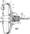
【図1】 本発明による空気圧ブレーキブースタの概略断面図である。
【図2】 本発明の1つの可能な実施例によるブースタの一部分の断面図である。
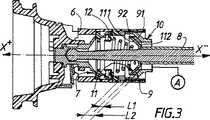
【図3】 図1に示したブースタの一部分の断面図である。
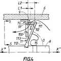
【図4】 本発明の他の可能な実施例によるブースタの一部分の断面図である。
【図5】 環状支持体を透明であると仮定して、図4の矢印5−5で記した方向でとった部分的正面図である。
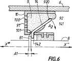
【図6】 本発明の他の可能な実施例によるブースタの一部分の断面図である。
【図7】 図6の実施例で用いられる傾動部材の斜視図である。[0001]
The present invention includes a rigid casing; a movable wall defining an interior of the casing with a front chamber and a rear chamber connected to a first pressure source that delivers a first pressure in an operating state; A pneumatic piston terminating in a hub slidably mounted in an opening of the casing; and a second pressure stored in the hub, the rear chamber delivering a second pressure higher than the first pressure source and the first pressure A three-way valve capable of selectively taking rest and drive states respectively connected to the source; a first axis between the first and second extreme positions when the valve is in its rest and drive states, respectively An operating rod mounted in the hub slidably in the direction and receiving an elastic force acting in a second axial direction opposite to the first axial direction; inserted between the second pressure source and the rear chamber; Annular cleaning housed in the hub around the operating rod About Pneumatic brake booster comprising a filter.
[0002]
This type of device is well known in the prior art and is described, for example, in FIG. 1 of patent document FR-2,706,403.
[0003]
For example, the current work disclosed in the patent documents EP 0,796,188 and FR-2,731,668 makes it possible in particular to reduce the response time and operating noise of the booster.
[0004]
However, the search for further progress in this area has led to a review of air filtration and noise issues at the booster inlet, with the goal of making the filter more selectable, booster response time. Is to make it even more important.
[0005]
The present invention is related to this, and its object is to provide a booster in which the filter automatically adapts to the stress transmitted to the booster.
[0006]
For this purpose, the booster of the invention according to the above introduction essentially consists of the filter being made of a compressible material, the first side of the filter being held fixed to the hub, and the second side of the filter being the hub Is dynamically linked to the actuating rod so that it can be displaced with respect to the filter, and the filter has a volume that varies with the displacement of its second surface, and the filter is compressed when the actuating rod is in its first extreme position. The filter is characterized by having a minimum volume that is in a closed state and a maximum volume that is in a relaxed state when the actuating rod is in its second extreme position.
[0007]
These features make filtration more selectable, increasing the degree of displacement of the actuating rod relative to the hub, and this parameter provides an accurate measure of the strength of the stress transmitted to the booster. Yes.
[0008]
The booster of the present invention may include an annular support secured to the hub, to which the first surface of the filter is attached and the second surface of the filter is attached to the outer edge of the flange. The inner edge of the flange is fixed to the operating rod.
[0009]
In one possible embodiment of the invention, the flange continues from the annular support in the first axial direction, and the second surface of the filter continues from the first surface in the first axial direction.
[0010]
In another possible embodiment of the invention, at least a part of the second surface of the filter is dynamically associated with the working area of the tilting member resting on both the hub and the actuating rod, the first of the actuating rod relative to the hub. The width displacement produces a second width displacement that is greater than the first width of the working area relative to the hub.
[0011]
Finally, the filter may be formed of a porous polymer whose first and second surfaces are bonded to an annular support, flange or tilting member, or elastically to these components. Pause.
[0012]
Other features and advantages of the present invention will become apparent from the following description, given by way of non-limiting example and with reference to the accompanying drawings.
[0013]
Since the present invention relates to improvements to the pneumatic booster and the general construction and operation of this booster are well known to those skilled in the art, the improvements provided by the present invention can be generally understood here. Let us recall the principle of this device.
[0014]
In general, a pneumatic brake booster essentially includes a rigid casing 1; a movable wall 2; a
[0015]
The movable wall 2 defines a front chamber 3 and a
[0016]
The
[0017]
The three-
[0018]
The
[0019]
The
[0020]
The
[0021]
According to the present invention, the
[0022]
More specifically, the
[0023]
For example, as shown in FIGS. 2 to 4, the booster of the present invention includes an
[0024]
In the embodiment illustrated in FIG. 2, the
[0025]
However, the
[0026]
The flange itself may be made of metal (Fig. 3), rigid polymer (Fig. 2), flat (Fig. 2), conical and rigid (Fig. 3), or alternatively As shown in FIG. 4, which will be described later in detail, it may be flexible.
[0027]
2 and 3, the
[0028]
Nevertheless, in the example illustrated in FIGS. 2-5, the change in the volume of the
[0029]
4 and 5, the
[0030]
For example, the flange is formed of a
[0031]
The
[0032]
Thus, the movement of the
[0033]
Next, all that is required is contact of the
[0034]
FIGS. 6 and 7 illustrate another embodiment of the present invention, which also transmits a displacement to the
[0035]
For this reason, at least a
[0036]
In other words, some points of the tilting member are fixed to the hub, while other points of the tilting member are fixed to the actuating rod.
[0037]
In this case, the tilting
[0038]
The
[0039]
In this way, the tilting
[0040]
In the embodiment of FIGS. 6 and 7, the filter is very beneficially formed of a porous polymer with elastic properties, so that the
[0041]
In the other embodiment shown, however, it is possible to form the filter with a porous polymer, which may or may not be elastic, the
[Brief description of the drawings]
FIG. 1 is a schematic cross-sectional view of a pneumatic brake booster according to the present invention.
FIG. 2 is a cross-sectional view of a portion of a booster according to one possible embodiment of the present invention.
FIG. 3 is a cross-sectional view of a part of the booster shown in FIG.
FIG. 4 is a cross-sectional view of a portion of a booster according to another possible embodiment of the present invention.
FIG. 5 is a partial front view taken in the direction indicated by arrows 5-5 in FIG. 4, assuming the annular support is transparent.
FIG. 6 is a cross-sectional view of a portion of a booster according to another possible embodiment of the present invention.
7 is a perspective view of a tilting member used in the embodiment of FIG.
Claims (6)
Translated fromJapaneseApplications Claiming Priority (3)
| Application Number | Priority Date | Filing Date | Title |
|---|---|---|---|
| FR9802378AFR2775460B1 (en) | 1998-02-27 | 1998-02-27 | SERVOMOTOR USING A CONTROLLED DENSITY FILTER |
| FR98/02378 | 1998-02-27 | ||
| PCT/FR1999/000391WO1999043526A1 (en) | 1998-02-27 | 1999-02-22 | Servomotor using a controlled density filter |
Publications (2)
| Publication Number | Publication Date |
|---|---|
| JP2002504458A JP2002504458A (en) | 2002-02-12 |
| JP4283442B2true JP4283442B2 (en) | 2009-06-24 |
Family
ID=9523432
Family Applications (1)
| Application Number | Title | Priority Date | Filing Date |
|---|---|---|---|
| JP2000533298AExpired - Fee RelatedJP4283442B2 (en) | 1998-02-27 | 1999-02-22 | Booster with controlled density filter |
Country Status (7)
| Country | Link |
|---|---|
| US (1) | US6119578A (en) |
| EP (1) | EP1056633B1 (en) |
| JP (1) | JP4283442B2 (en) |
| DE (1) | DE69902009T2 (en) |
| ES (1) | ES2177233T3 (en) |
| FR (1) | FR2775460B1 (en) |
| WO (1) | WO1999043526A1 (en) |
Families Citing this family (5)
| Publication number | Priority date | Publication date | Assignee | Title |
|---|---|---|---|---|
| JP2000280889A (en)* | 1999-03-30 | 2000-10-10 | Fuji Heavy Ind Ltd | Brake booster |
| DE10161436C1 (en)* | 2001-12-14 | 2003-07-03 | Porsche Ag | Ansauggeräuschdämpfer |
| DE10256366B4 (en)* | 2002-12-03 | 2004-10-28 | Lucas Automotive Gmbh | Brake booster |
| KR102008241B1 (en)* | 2017-06-13 | 2019-08-07 | 주식회사 만도 | The break booster of the vehicle |
| FR3095629B1 (en)* | 2019-04-30 | 2021-04-16 | Psa Automobiles Sa | VARIABLE FILTERED AIR INTAKE VALVE FOR PNEUMATIC AMPLIFIER |
Family Cites Families (7)
| Publication number | Priority date | Publication date | Assignee | Title |
|---|---|---|---|---|
| US3499288A (en)* | 1967-12-05 | 1970-03-10 | Glenn T Randol | Vacuum-operated brake booster device |
| US3897716A (en)* | 1973-08-20 | 1975-08-05 | Bendix Corp | Flow control means for a servomotor |
| US3972263A (en)* | 1975-02-19 | 1976-08-03 | The Bendix Corporation | Flow control valve means for a servomotor |
| DE3510844A1 (en)* | 1985-03-26 | 1986-10-09 | FAG Kugelfischer Georg Schäfer KGaA, 8720 Schweinfurt | Vacuum brake booster |
| FR2706403B1 (en) | 1993-06-14 | 1995-09-01 | Alliedsignal Europ Services | Porous bellows actuator forming a filter. |
| FR2727924A1 (en) | 1994-12-09 | 1996-06-14 | Alliedsignal Europ Services | SERVOMOTOR WITH ADAPTIVE ADDITIONAL AIR INTAKE |
| FR2731668B1 (en) | 1995-03-17 | 1997-05-16 | Alliedsignal Europ Services | SERVOMOTOR WITH ADAPTIVE FLOW DIRECT AIR INTAKE |
- 1998
- 1998-02-27FRFR9802378Apatent/FR2775460B1/ennot_activeExpired - Fee Related
- 1999
- 1999-02-22USUS09/269,160patent/US6119578A/ennot_activeExpired - Lifetime
- 1999-02-22WOPCT/FR1999/000391patent/WO1999043526A1/enactiveIP Right Grant
- 1999-02-22EPEP99904924Apatent/EP1056633B1/ennot_activeExpired - Lifetime
- 1999-02-22ESES99904924Tpatent/ES2177233T3/ennot_activeExpired - Lifetime
- 1999-02-22JPJP2000533298Apatent/JP4283442B2/ennot_activeExpired - Fee Related
- 1999-02-22DEDE69902009Tpatent/DE69902009T2/ennot_activeExpired - Lifetime
Also Published As
| Publication number | Publication date |
|---|---|
| DE69902009D1 (en) | 2002-08-08 |
| EP1056633A1 (en) | 2000-12-06 |
| WO1999043526A1 (en) | 1999-09-02 |
| DE69902009T2 (en) | 2003-01-30 |
| ES2177233T3 (en) | 2002-12-01 |
| JP2002504458A (en) | 2002-02-12 |
| FR2775460A1 (en) | 1999-09-03 |
| EP1056633B1 (en) | 2002-07-03 |
| US6119578A (en) | 2000-09-19 |
| FR2775460B1 (en) | 2000-04-21 |
Similar Documents
| Publication | Publication Date | Title |
|---|---|---|
| KR0135970B1 (en) | Pneumatic brake booster control valve assembly | |
| CN107007208B (en) | Suction cleaning device | |
| US4852620A (en) | Pipette with inverted bellows | |
| KR100298464B1 (en) | Pneumatic booster | |
| KR960703191A (en) | FLUID-OPERATED SPRING BRAKE ACTUATOR WITH IMPROVED PRESSURE PLATE | |
| US6173963B1 (en) | Sealing assembly for an inlet valve of a power nailer | |
| JP4283442B2 (en) | Booster with controlled density filter | |
| US20070252375A1 (en) | Damping Device | |
| CA2438073A1 (en) | A vacuum cleaner | |
| JP5276621B2 (en) | Hand-held tool with oscillating linear drive | |
| GB2142396A (en) | Improvements in or relating to brake boosters or servos | |
| JPH11320472A (en) | Fluid-actuated grasping device | |
| WO2008091025A1 (en) | Disc brake device | |
| US4806084A (en) | Hand-held vacuum pump | |
| US3951046A (en) | Push rod and tappet assembly | |
| EP0809028A2 (en) | Neutral shaped pump diaphragm | |
| CN1260230A (en) | Filter device having vibrator | |
| JP4207170B2 (en) | Improved master cylinder with dynamically releasable fluid reaction force | |
| JP3785488B2 (en) | Booster with variable flow additional air intake | |
| JP2004003660A (en) | Quick air discharge device with improved discharge duct | |
| JP2008542003A (en) | Electric pipette | |
| JP2002516784A (en) | Pneumatic booster with floating reaction disk and dynamically nullable reaction force | |
| JPH09501367A (en) | Booster with porous bellows forming a filter | |
| US6121559A (en) | Bellows | |
| FR2853610B1 (en) | BRAKE PNEUMATIC ASSISTANCE ACTUATOR WITH REDUCED OPERATING NOISE |
Legal Events
| Date | Code | Title | Description |
|---|---|---|---|
| A621 | Written request for application examination | Free format text:JAPANESE INTERMEDIATE CODE: A621 Effective date:20060221 | |
| TRDD | Decision of grant or rejection written | ||
| A01 | Written decision to grant a patent or to grant a registration (utility model) | Free format text:JAPANESE INTERMEDIATE CODE: A01 Effective date:20090218 | |
| A01 | Written decision to grant a patent or to grant a registration (utility model) | Free format text:JAPANESE INTERMEDIATE CODE: A01 | |
| A61 | First payment of annual fees (during grant procedure) | Free format text:JAPANESE INTERMEDIATE CODE: A61 Effective date:20090319 | |
| R150 | Certificate of patent or registration of utility model | Free format text:JAPANESE INTERMEDIATE CODE: R150 | |
| FPAY | Renewal fee payment (event date is renewal date of database) | Free format text:PAYMENT UNTIL: 20120327 Year of fee payment:3 | |
| FPAY | Renewal fee payment (event date is renewal date of database) | Free format text:PAYMENT UNTIL: 20130327 Year of fee payment:4 | |
| FPAY | Renewal fee payment (event date is renewal date of database) | Free format text:PAYMENT UNTIL: 20140327 Year of fee payment:5 | |
| R250 | Receipt of annual fees | Free format text:JAPANESE INTERMEDIATE CODE: R250 | |
| R250 | Receipt of annual fees | Free format text:JAPANESE INTERMEDIATE CODE: R250 | |
| R250 | Receipt of annual fees | Free format text:JAPANESE INTERMEDIATE CODE: R250 | |
| LAPS | Cancellation because of no payment of annual fees |