JP4282826B2 - Modular glenoid assembly - Google Patents
Modular glenoid assemblyDownload PDFInfo
- Publication number
- JP4282826B2 JP4282826B2JP16133599AJP16133599AJP4282826B2JP 4282826 B2JP4282826 B2JP 4282826B2JP 16133599 AJP16133599 AJP 16133599AJP 16133599 AJP16133599 AJP 16133599AJP 4282826 B2JP4282826 B2JP 4282826B2
- Authority
- JP
- Japan
- Prior art keywords
- base
- insert
- groove
- glenoid
- support
- Prior art date
- Legal status (The legal status is an assumption and is not a legal conclusion. Google has not performed a legal analysis and makes no representation as to the accuracy of the status listed.)
- Expired - Fee Related
Links
Images


Classifications
- A—HUMAN NECESSITIES
- A61—MEDICAL OR VETERINARY SCIENCE; HYGIENE
- A61F—FILTERS IMPLANTABLE INTO BLOOD VESSELS; PROSTHESES; DEVICES PROVIDING PATENCY TO, OR PREVENTING COLLAPSING OF, TUBULAR STRUCTURES OF THE BODY, e.g. STENTS; ORTHOPAEDIC, NURSING OR CONTRACEPTIVE DEVICES; FOMENTATION; TREATMENT OR PROTECTION OF EYES OR EARS; BANDAGES, DRESSINGS OR ABSORBENT PADS; FIRST-AID KITS
- A61F2/00—Filters implantable into blood vessels; Prostheses, i.e. artificial substitutes or replacements for parts of the body; Appliances for connecting them with the body; Devices providing patency to, or preventing collapsing of, tubular structures of the body, e.g. stents
- A61F2/02—Prostheses implantable into the body
- A61F2/30—Joints
- A61F2/40—Joints for shoulders
- A61F2/4081—Glenoid components, e.g. cups
- A—HUMAN NECESSITIES
- A61—MEDICAL OR VETERINARY SCIENCE; HYGIENE
- A61B—DIAGNOSIS; SURGERY; IDENTIFICATION
- A61B17/00—Surgical instruments, devices or methods
- A61B17/56—Surgical instruments or methods for treatment of bones or joints; Devices specially adapted therefor
- A61B17/58—Surgical instruments or methods for treatment of bones or joints; Devices specially adapted therefor for osteosynthesis, e.g. bone plates, screws or setting implements
- A61B17/68—Internal fixation devices, including fasteners and spinal fixators, even if a part thereof projects from the skin
- A61B17/84—Fasteners therefor or fasteners being internal fixation devices
- A61B17/86—Pins or screws or threaded wires; nuts therefor
- A—HUMAN NECESSITIES
- A61—MEDICAL OR VETERINARY SCIENCE; HYGIENE
- A61F—FILTERS IMPLANTABLE INTO BLOOD VESSELS; PROSTHESES; DEVICES PROVIDING PATENCY TO, OR PREVENTING COLLAPSING OF, TUBULAR STRUCTURES OF THE BODY, e.g. STENTS; ORTHOPAEDIC, NURSING OR CONTRACEPTIVE DEVICES; FOMENTATION; TREATMENT OR PROTECTION OF EYES OR EARS; BANDAGES, DRESSINGS OR ABSORBENT PADS; FIRST-AID KITS
- A61F2/00—Filters implantable into blood vessels; Prostheses, i.e. artificial substitutes or replacements for parts of the body; Appliances for connecting them with the body; Devices providing patency to, or preventing collapsing of, tubular structures of the body, e.g. stents
- A61F2/02—Prostheses implantable into the body
- A61F2/30—Joints
- A61F2/40—Joints for shoulders
- A—HUMAN NECESSITIES
- A61—MEDICAL OR VETERINARY SCIENCE; HYGIENE
- A61F—FILTERS IMPLANTABLE INTO BLOOD VESSELS; PROSTHESES; DEVICES PROVIDING PATENCY TO, OR PREVENTING COLLAPSING OF, TUBULAR STRUCTURES OF THE BODY, e.g. STENTS; ORTHOPAEDIC, NURSING OR CONTRACEPTIVE DEVICES; FOMENTATION; TREATMENT OR PROTECTION OF EYES OR EARS; BANDAGES, DRESSINGS OR ABSORBENT PADS; FIRST-AID KITS
- A61F2/00—Filters implantable into blood vessels; Prostheses, i.e. artificial substitutes or replacements for parts of the body; Appliances for connecting them with the body; Devices providing patency to, or preventing collapsing of, tubular structures of the body, e.g. stents
- A61F2/02—Prostheses implantable into the body
- A61F2/30—Joints
- A61F2002/30001—Additional features of subject-matter classified in A61F2/28, A61F2/30 and subgroups thereof
- A61F2002/30108—Shapes
- A61F2002/3011—Cross-sections or two-dimensional shapes
- A61F2002/30112—Rounded shapes, e.g. with rounded corners
- A61F2002/30125—Rounded shapes, e.g. with rounded corners elliptical or oval
- A—HUMAN NECESSITIES
- A61—MEDICAL OR VETERINARY SCIENCE; HYGIENE
- A61F—FILTERS IMPLANTABLE INTO BLOOD VESSELS; PROSTHESES; DEVICES PROVIDING PATENCY TO, OR PREVENTING COLLAPSING OF, TUBULAR STRUCTURES OF THE BODY, e.g. STENTS; ORTHOPAEDIC, NURSING OR CONTRACEPTIVE DEVICES; FOMENTATION; TREATMENT OR PROTECTION OF EYES OR EARS; BANDAGES, DRESSINGS OR ABSORBENT PADS; FIRST-AID KITS
- A61F2/00—Filters implantable into blood vessels; Prostheses, i.e. artificial substitutes or replacements for parts of the body; Appliances for connecting them with the body; Devices providing patency to, or preventing collapsing of, tubular structures of the body, e.g. stents
- A61F2/02—Prostheses implantable into the body
- A61F2/30—Joints
- A61F2002/30001—Additional features of subject-matter classified in A61F2/28, A61F2/30 and subgroups thereof
- A61F2002/30108—Shapes
- A61F2002/3011—Cross-sections or two-dimensional shapes
- A61F2002/30138—Convex polygonal shapes
- A61F2002/30153—Convex polygonal shapes rectangular
- A—HUMAN NECESSITIES
- A61—MEDICAL OR VETERINARY SCIENCE; HYGIENE
- A61F—FILTERS IMPLANTABLE INTO BLOOD VESSELS; PROSTHESES; DEVICES PROVIDING PATENCY TO, OR PREVENTING COLLAPSING OF, TUBULAR STRUCTURES OF THE BODY, e.g. STENTS; ORTHOPAEDIC, NURSING OR CONTRACEPTIVE DEVICES; FOMENTATION; TREATMENT OR PROTECTION OF EYES OR EARS; BANDAGES, DRESSINGS OR ABSORBENT PADS; FIRST-AID KITS
- A61F2/00—Filters implantable into blood vessels; Prostheses, i.e. artificial substitutes or replacements for parts of the body; Appliances for connecting them with the body; Devices providing patency to, or preventing collapsing of, tubular structures of the body, e.g. stents
- A61F2/02—Prostheses implantable into the body
- A61F2/30—Joints
- A61F2002/30001—Additional features of subject-matter classified in A61F2/28, A61F2/30 and subgroups thereof
- A61F2002/30316—The prosthesis having different structural features at different locations within the same prosthesis; Connections between prosthetic parts; Special structural features of bone or joint prostheses not otherwise provided for
- A61F2002/30329—Connections or couplings between prosthetic parts, e.g. between modular parts; Connecting elements
- A61F2002/30383—Connections or couplings between prosthetic parts, e.g. between modular parts; Connecting elements made by laterally inserting a protrusion, e.g. a rib into a complementarily-shaped groove
- A61F2002/3039—Connections or couplings between prosthetic parts, e.g. between modular parts; Connecting elements made by laterally inserting a protrusion, e.g. a rib into a complementarily-shaped groove with possibility of relative movement of the rib within the groove
- A61F2002/30398—Sliding
- A61F2002/30401—Sliding with additional means for preventing or locking said sliding
- A—HUMAN NECESSITIES
- A61—MEDICAL OR VETERINARY SCIENCE; HYGIENE
- A61F—FILTERS IMPLANTABLE INTO BLOOD VESSELS; PROSTHESES; DEVICES PROVIDING PATENCY TO, OR PREVENTING COLLAPSING OF, TUBULAR STRUCTURES OF THE BODY, e.g. STENTS; ORTHOPAEDIC, NURSING OR CONTRACEPTIVE DEVICES; FOMENTATION; TREATMENT OR PROTECTION OF EYES OR EARS; BANDAGES, DRESSINGS OR ABSORBENT PADS; FIRST-AID KITS
- A61F2/00—Filters implantable into blood vessels; Prostheses, i.e. artificial substitutes or replacements for parts of the body; Appliances for connecting them with the body; Devices providing patency to, or preventing collapsing of, tubular structures of the body, e.g. stents
- A61F2/02—Prostheses implantable into the body
- A61F2/30—Joints
- A61F2002/30001—Additional features of subject-matter classified in A61F2/28, A61F2/30 and subgroups thereof
- A61F2002/30316—The prosthesis having different structural features at different locations within the same prosthesis; Connections between prosthetic parts; Special structural features of bone or joint prostheses not otherwise provided for
- A61F2002/30329—Connections or couplings between prosthetic parts, e.g. between modular parts; Connecting elements
- A61F2002/30476—Connections or couplings between prosthetic parts, e.g. between modular parts; Connecting elements locked by an additional locking mechanism
- A61F2002/305—Snap connection
- A—HUMAN NECESSITIES
- A61—MEDICAL OR VETERINARY SCIENCE; HYGIENE
- A61F—FILTERS IMPLANTABLE INTO BLOOD VESSELS; PROSTHESES; DEVICES PROVIDING PATENCY TO, OR PREVENTING COLLAPSING OF, TUBULAR STRUCTURES OF THE BODY, e.g. STENTS; ORTHOPAEDIC, NURSING OR CONTRACEPTIVE DEVICES; FOMENTATION; TREATMENT OR PROTECTION OF EYES OR EARS; BANDAGES, DRESSINGS OR ABSORBENT PADS; FIRST-AID KITS
- A61F2/00—Filters implantable into blood vessels; Prostheses, i.e. artificial substitutes or replacements for parts of the body; Appliances for connecting them with the body; Devices providing patency to, or preventing collapsing of, tubular structures of the body, e.g. stents
- A61F2/02—Prostheses implantable into the body
- A61F2/30—Joints
- A61F2002/30001—Additional features of subject-matter classified in A61F2/28, A61F2/30 and subgroups thereof
- A61F2002/30316—The prosthesis having different structural features at different locations within the same prosthesis; Connections between prosthetic parts; Special structural features of bone or joint prostheses not otherwise provided for
- A61F2002/30535—Special structural features of bone or joint prostheses not otherwise provided for
- A61F2002/30604—Special structural features of bone or joint prostheses not otherwise provided for modular
- A—HUMAN NECESSITIES
- A61—MEDICAL OR VETERINARY SCIENCE; HYGIENE
- A61F—FILTERS IMPLANTABLE INTO BLOOD VESSELS; PROSTHESES; DEVICES PROVIDING PATENCY TO, OR PREVENTING COLLAPSING OF, TUBULAR STRUCTURES OF THE BODY, e.g. STENTS; ORTHOPAEDIC, NURSING OR CONTRACEPTIVE DEVICES; FOMENTATION; TREATMENT OR PROTECTION OF EYES OR EARS; BANDAGES, DRESSINGS OR ABSORBENT PADS; FIRST-AID KITS
- A61F2/00—Filters implantable into blood vessels; Prostheses, i.e. artificial substitutes or replacements for parts of the body; Appliances for connecting them with the body; Devices providing patency to, or preventing collapsing of, tubular structures of the body, e.g. stents
- A61F2/02—Prostheses implantable into the body
- A61F2/30—Joints
- A61F2/30767—Special external or bone-contacting surface, e.g. coating for improving bone ingrowth
- A61F2/30771—Special external or bone-contacting surface, e.g. coating for improving bone ingrowth applied in original prostheses, e.g. holes or grooves
- A61F2002/30772—Apertures or holes, e.g. of circular cross section
- A61F2002/30784—Plurality of holes
- A61F2002/30787—Plurality of holes inclined obliquely with respect to each other
- A—HUMAN NECESSITIES
- A61—MEDICAL OR VETERINARY SCIENCE; HYGIENE
- A61F—FILTERS IMPLANTABLE INTO BLOOD VESSELS; PROSTHESES; DEVICES PROVIDING PATENCY TO, OR PREVENTING COLLAPSING OF, TUBULAR STRUCTURES OF THE BODY, e.g. STENTS; ORTHOPAEDIC, NURSING OR CONTRACEPTIVE DEVICES; FOMENTATION; TREATMENT OR PROTECTION OF EYES OR EARS; BANDAGES, DRESSINGS OR ABSORBENT PADS; FIRST-AID KITS
- A61F2/00—Filters implantable into blood vessels; Prostheses, i.e. artificial substitutes or replacements for parts of the body; Appliances for connecting them with the body; Devices providing patency to, or preventing collapsing of, tubular structures of the body, e.g. stents
- A61F2/02—Prostheses implantable into the body
- A61F2/30—Joints
- A61F2/30767—Special external or bone-contacting surface, e.g. coating for improving bone ingrowth
- A61F2/30771—Special external or bone-contacting surface, e.g. coating for improving bone ingrowth applied in original prostheses, e.g. holes or grooves
- A61F2002/30772—Apertures or holes, e.g. of circular cross section
- A61F2002/3079—Stepped or enlarged apertures, e.g. having discrete diameter changes
- A—HUMAN NECESSITIES
- A61—MEDICAL OR VETERINARY SCIENCE; HYGIENE
- A61F—FILTERS IMPLANTABLE INTO BLOOD VESSELS; PROSTHESES; DEVICES PROVIDING PATENCY TO, OR PREVENTING COLLAPSING OF, TUBULAR STRUCTURES OF THE BODY, e.g. STENTS; ORTHOPAEDIC, NURSING OR CONTRACEPTIVE DEVICES; FOMENTATION; TREATMENT OR PROTECTION OF EYES OR EARS; BANDAGES, DRESSINGS OR ABSORBENT PADS; FIRST-AID KITS
- A61F2/00—Filters implantable into blood vessels; Prostheses, i.e. artificial substitutes or replacements for parts of the body; Appliances for connecting them with the body; Devices providing patency to, or preventing collapsing of, tubular structures of the body, e.g. stents
- A61F2/02—Prostheses implantable into the body
- A61F2/30—Joints
- A61F2/30767—Special external or bone-contacting surface, e.g. coating for improving bone ingrowth
- A61F2/30771—Special external or bone-contacting surface, e.g. coating for improving bone ingrowth applied in original prostheses, e.g. holes or grooves
- A61F2002/30795—Blind bores, e.g. of circular cross-section
- A61F2002/308—Blind bores, e.g. of circular cross-section oblong
- A—HUMAN NECESSITIES
- A61—MEDICAL OR VETERINARY SCIENCE; HYGIENE
- A61F—FILTERS IMPLANTABLE INTO BLOOD VESSELS; PROSTHESES; DEVICES PROVIDING PATENCY TO, OR PREVENTING COLLAPSING OF, TUBULAR STRUCTURES OF THE BODY, e.g. STENTS; ORTHOPAEDIC, NURSING OR CONTRACEPTIVE DEVICES; FOMENTATION; TREATMENT OR PROTECTION OF EYES OR EARS; BANDAGES, DRESSINGS OR ABSORBENT PADS; FIRST-AID KITS
- A61F2/00—Filters implantable into blood vessels; Prostheses, i.e. artificial substitutes or replacements for parts of the body; Appliances for connecting them with the body; Devices providing patency to, or preventing collapsing of, tubular structures of the body, e.g. stents
- A61F2/02—Prostheses implantable into the body
- A61F2/30—Joints
- A61F2/30767—Special external or bone-contacting surface, e.g. coating for improving bone ingrowth
- A61F2/30771—Special external or bone-contacting surface, e.g. coating for improving bone ingrowth applied in original prostheses, e.g. holes or grooves
- A61F2002/3082—Grooves
- A—HUMAN NECESSITIES
- A61—MEDICAL OR VETERINARY SCIENCE; HYGIENE
- A61F—FILTERS IMPLANTABLE INTO BLOOD VESSELS; PROSTHESES; DEVICES PROVIDING PATENCY TO, OR PREVENTING COLLAPSING OF, TUBULAR STRUCTURES OF THE BODY, e.g. STENTS; ORTHOPAEDIC, NURSING OR CONTRACEPTIVE DEVICES; FOMENTATION; TREATMENT OR PROTECTION OF EYES OR EARS; BANDAGES, DRESSINGS OR ABSORBENT PADS; FIRST-AID KITS
- A61F2/00—Filters implantable into blood vessels; Prostheses, i.e. artificial substitutes or replacements for parts of the body; Appliances for connecting them with the body; Devices providing patency to, or preventing collapsing of, tubular structures of the body, e.g. stents
- A61F2/02—Prostheses implantable into the body
- A61F2/30—Joints
- A61F2/30767—Special external or bone-contacting surface, e.g. coating for improving bone ingrowth
- A61F2/30771—Special external or bone-contacting surface, e.g. coating for improving bone ingrowth applied in original prostheses, e.g. holes or grooves
- A61F2002/30841—Sharp anchoring protrusions for impaction into the bone, e.g. sharp pins, spikes
- A—HUMAN NECESSITIES
- A61—MEDICAL OR VETERINARY SCIENCE; HYGIENE
- A61F—FILTERS IMPLANTABLE INTO BLOOD VESSELS; PROSTHESES; DEVICES PROVIDING PATENCY TO, OR PREVENTING COLLAPSING OF, TUBULAR STRUCTURES OF THE BODY, e.g. STENTS; ORTHOPAEDIC, NURSING OR CONTRACEPTIVE DEVICES; FOMENTATION; TREATMENT OR PROTECTION OF EYES OR EARS; BANDAGES, DRESSINGS OR ABSORBENT PADS; FIRST-AID KITS
- A61F2/00—Filters implantable into blood vessels; Prostheses, i.e. artificial substitutes or replacements for parts of the body; Appliances for connecting them with the body; Devices providing patency to, or preventing collapsing of, tubular structures of the body, e.g. stents
- A61F2/02—Prostheses implantable into the body
- A61F2/30—Joints
- A61F2/30767—Special external or bone-contacting surface, e.g. coating for improving bone ingrowth
- A61F2/30771—Special external or bone-contacting surface, e.g. coating for improving bone ingrowth applied in original prostheses, e.g. holes or grooves
- A61F2002/30878—Special external or bone-contacting surface, e.g. coating for improving bone ingrowth applied in original prostheses, e.g. holes or grooves with non-sharp protrusions, for instance contacting the bone for anchoring, e.g. keels, pegs, pins, posts, shanks, stems, struts
- A61F2002/30891—Plurality of protrusions
- A61F2002/30892—Plurality of protrusions parallel
- A—HUMAN NECESSITIES
- A61—MEDICAL OR VETERINARY SCIENCE; HYGIENE
- A61F—FILTERS IMPLANTABLE INTO BLOOD VESSELS; PROSTHESES; DEVICES PROVIDING PATENCY TO, OR PREVENTING COLLAPSING OF, TUBULAR STRUCTURES OF THE BODY, e.g. STENTS; ORTHOPAEDIC, NURSING OR CONTRACEPTIVE DEVICES; FOMENTATION; TREATMENT OR PROTECTION OF EYES OR EARS; BANDAGES, DRESSINGS OR ABSORBENT PADS; FIRST-AID KITS
- A61F2/00—Filters implantable into blood vessels; Prostheses, i.e. artificial substitutes or replacements for parts of the body; Appliances for connecting them with the body; Devices providing patency to, or preventing collapsing of, tubular structures of the body, e.g. stents
- A61F2/02—Prostheses implantable into the body
- A61F2/30—Joints
- A61F2/40—Joints for shoulders
- A61F2/4014—Humeral heads or necks; Connections of endoprosthetic heads or necks to endoprosthetic humeral shafts
- A61F2002/4018—Heads or epiphyseal parts of humerus
- A—HUMAN NECESSITIES
- A61—MEDICAL OR VETERINARY SCIENCE; HYGIENE
- A61F—FILTERS IMPLANTABLE INTO BLOOD VESSELS; PROSTHESES; DEVICES PROVIDING PATENCY TO, OR PREVENTING COLLAPSING OF, TUBULAR STRUCTURES OF THE BODY, e.g. STENTS; ORTHOPAEDIC, NURSING OR CONTRACEPTIVE DEVICES; FOMENTATION; TREATMENT OR PROTECTION OF EYES OR EARS; BANDAGES, DRESSINGS OR ABSORBENT PADS; FIRST-AID KITS
- A61F2/00—Filters implantable into blood vessels; Prostheses, i.e. artificial substitutes or replacements for parts of the body; Appliances for connecting them with the body; Devices providing patency to, or preventing collapsing of, tubular structures of the body, e.g. stents
- A61F2/02—Prostheses implantable into the body
- A61F2/30—Joints
- A61F2/40—Joints for shoulders
- A61F2/4059—Humeral shafts
- A61F2002/4062—Proximal or metaphyseal parts of shafts
- A—HUMAN NECESSITIES
- A61—MEDICAL OR VETERINARY SCIENCE; HYGIENE
- A61F—FILTERS IMPLANTABLE INTO BLOOD VESSELS; PROSTHESES; DEVICES PROVIDING PATENCY TO, OR PREVENTING COLLAPSING OF, TUBULAR STRUCTURES OF THE BODY, e.g. STENTS; ORTHOPAEDIC, NURSING OR CONTRACEPTIVE DEVICES; FOMENTATION; TREATMENT OR PROTECTION OF EYES OR EARS; BANDAGES, DRESSINGS OR ABSORBENT PADS; FIRST-AID KITS
- A61F2/00—Filters implantable into blood vessels; Prostheses, i.e. artificial substitutes or replacements for parts of the body; Appliances for connecting them with the body; Devices providing patency to, or preventing collapsing of, tubular structures of the body, e.g. stents
- A61F2/02—Prostheses implantable into the body
- A61F2/30—Joints
- A61F2/46—Special tools for implanting artificial joints
- A61F2002/4631—Special tools for implanting artificial joints the prosthesis being specially adapted for being cemented
- A—HUMAN NECESSITIES
- A61—MEDICAL OR VETERINARY SCIENCE; HYGIENE
- A61F—FILTERS IMPLANTABLE INTO BLOOD VESSELS; PROSTHESES; DEVICES PROVIDING PATENCY TO, OR PREVENTING COLLAPSING OF, TUBULAR STRUCTURES OF THE BODY, e.g. STENTS; ORTHOPAEDIC, NURSING OR CONTRACEPTIVE DEVICES; FOMENTATION; TREATMENT OR PROTECTION OF EYES OR EARS; BANDAGES, DRESSINGS OR ABSORBENT PADS; FIRST-AID KITS
- A61F2220/00—Fixations or connections for prostheses classified in groups A61F2/00 - A61F2/26 or A61F2/82 or A61F9/00 or A61F11/00 or subgroups thereof
- A61F2220/0025—Connections or couplings between prosthetic parts, e.g. between modular parts; Connecting elements
- A—HUMAN NECESSITIES
- A61—MEDICAL OR VETERINARY SCIENCE; HYGIENE
- A61F—FILTERS IMPLANTABLE INTO BLOOD VESSELS; PROSTHESES; DEVICES PROVIDING PATENCY TO, OR PREVENTING COLLAPSING OF, TUBULAR STRUCTURES OF THE BODY, e.g. STENTS; ORTHOPAEDIC, NURSING OR CONTRACEPTIVE DEVICES; FOMENTATION; TREATMENT OR PROTECTION OF EYES OR EARS; BANDAGES, DRESSINGS OR ABSORBENT PADS; FIRST-AID KITS
- A61F2230/00—Geometry of prostheses classified in groups A61F2/00 - A61F2/26 or A61F2/82 or A61F9/00 or A61F11/00 or subgroups thereof
- A61F2230/0002—Two-dimensional shapes, e.g. cross-sections
- A61F2230/0004—Rounded shapes, e.g. with rounded corners
- A61F2230/0008—Rounded shapes, e.g. with rounded corners elliptical or oval
- A—HUMAN NECESSITIES
- A61—MEDICAL OR VETERINARY SCIENCE; HYGIENE
- A61F—FILTERS IMPLANTABLE INTO BLOOD VESSELS; PROSTHESES; DEVICES PROVIDING PATENCY TO, OR PREVENTING COLLAPSING OF, TUBULAR STRUCTURES OF THE BODY, e.g. STENTS; ORTHOPAEDIC, NURSING OR CONTRACEPTIVE DEVICES; FOMENTATION; TREATMENT OR PROTECTION OF EYES OR EARS; BANDAGES, DRESSINGS OR ABSORBENT PADS; FIRST-AID KITS
- A61F2230/00—Geometry of prostheses classified in groups A61F2/00 - A61F2/26 or A61F2/82 or A61F9/00 or A61F11/00 or subgroups thereof
- A61F2230/0002—Two-dimensional shapes, e.g. cross-sections
- A61F2230/0017—Angular shapes
- A61F2230/0019—Angular shapes rectangular
- A—HUMAN NECESSITIES
- A61—MEDICAL OR VETERINARY SCIENCE; HYGIENE
- A61F—FILTERS IMPLANTABLE INTO BLOOD VESSELS; PROSTHESES; DEVICES PROVIDING PATENCY TO, OR PREVENTING COLLAPSING OF, TUBULAR STRUCTURES OF THE BODY, e.g. STENTS; ORTHOPAEDIC, NURSING OR CONTRACEPTIVE DEVICES; FOMENTATION; TREATMENT OR PROTECTION OF EYES OR EARS; BANDAGES, DRESSINGS OR ABSORBENT PADS; FIRST-AID KITS
- A61F2310/00—Prostheses classified in A61F2/28 or A61F2/30 - A61F2/44 being constructed from or coated with a particular material
- A61F2310/00005—The prosthesis being constructed from a particular material
- A61F2310/00011—Metals or alloys
- A61F2310/00017—Iron- or Fe-based alloys, e.g. stainless steel
- A—HUMAN NECESSITIES
- A61—MEDICAL OR VETERINARY SCIENCE; HYGIENE
- A61F—FILTERS IMPLANTABLE INTO BLOOD VESSELS; PROSTHESES; DEVICES PROVIDING PATENCY TO, OR PREVENTING COLLAPSING OF, TUBULAR STRUCTURES OF THE BODY, e.g. STENTS; ORTHOPAEDIC, NURSING OR CONTRACEPTIVE DEVICES; FOMENTATION; TREATMENT OR PROTECTION OF EYES OR EARS; BANDAGES, DRESSINGS OR ABSORBENT PADS; FIRST-AID KITS
- A61F2310/00—Prostheses classified in A61F2/28 or A61F2/30 - A61F2/44 being constructed from or coated with a particular material
- A61F2310/00005—The prosthesis being constructed from a particular material
- A61F2310/00011—Metals or alloys
- A61F2310/00023—Titanium or titanium-based alloys, e.g. Ti-Ni alloys
- A—HUMAN NECESSITIES
- A61—MEDICAL OR VETERINARY SCIENCE; HYGIENE
- A61F—FILTERS IMPLANTABLE INTO BLOOD VESSELS; PROSTHESES; DEVICES PROVIDING PATENCY TO, OR PREVENTING COLLAPSING OF, TUBULAR STRUCTURES OF THE BODY, e.g. STENTS; ORTHOPAEDIC, NURSING OR CONTRACEPTIVE DEVICES; FOMENTATION; TREATMENT OR PROTECTION OF EYES OR EARS; BANDAGES, DRESSINGS OR ABSORBENT PADS; FIRST-AID KITS
- A61F2310/00—Prostheses classified in A61F2/28 or A61F2/30 - A61F2/44 being constructed from or coated with a particular material
- A61F2310/00005—The prosthesis being constructed from a particular material
- A61F2310/00011—Metals or alloys
- A61F2310/00029—Cobalt-based alloys, e.g. Co-Cr alloys or Vitallium
Landscapes
- Health & Medical Sciences (AREA)
- Orthopedic Medicine & Surgery (AREA)
- Cardiology (AREA)
- Oral & Maxillofacial Surgery (AREA)
- Transplantation (AREA)
- Engineering & Computer Science (AREA)
- Biomedical Technology (AREA)
- Heart & Thoracic Surgery (AREA)
- Vascular Medicine (AREA)
- Life Sciences & Earth Sciences (AREA)
- Animal Behavior & Ethology (AREA)
- General Health & Medical Sciences (AREA)
- Public Health (AREA)
- Veterinary Medicine (AREA)
- Prostheses (AREA)
Description
Translated fromJapanese【0001】
【発明の属する技術分野】
本発明は人工関節窩部品(prosthetic glenoid component)に関し、特に天然の肩の窩(socket)を置換し上腕骨の頭部に支持面を設けるために肩甲骨の関節窩表面を取付けるためのモジュール型関節窩アセンブリーに関する。さらに詳細には本発明はプラスチック支持インサートに連結された金属裏打ちベースを備えたモジュール型関節窩アセンブリーに関する。
【0002】
【発明の概要】
本発明によれば、関節窩表面と連結するように適合されたベースと、上腕骨の頭部を係合させるように適合した支持面を備える支持インサートとを具備するモジュール型関節窩アセンブリーが提供される。このベースには第一コネクター部分が設けられ、またこのインサートには第二コネクター部分が設けられている。さらに、当該第一コネクター部分および第二コネクター部分は、インサートを移動してベースと係合させた時にそのインサートをベースに固定するように整合して(proportional)係合可能である。
【0003】
好ましい実施形態においては、この第一コネクター部分はベースの一部分の周囲に延在する溝を備え、第二コネクター部分はインサートの一部分の周囲に延在するタブを備えている。このタブは、インサートをベースに対して上方位置に移動した時に溝と係合して収容される。さらに、この溝は下方内側に開口する部分を備え、一方、タブは前記下方内側に延在する開口部分に収容される上方外側に延在する部分を備える。
【0004】
さらに本発明によれば、関節窩表面と連結するように適合されたベースと支持インサートとを備え、肩甲骨の関節窩に取付けて支持面を与えるモジュール型関節窩アセンブリーが提供される。ベースはリップを備え、支持インサートは、上腕骨部品の頭部に係合するように適合された支持面と、このインサートを当該ベースに対し上方位置に移動した時に当該リップに係合するように形成されたタブとを備えている。
【0005】
さらに本発明によれば、金属ベースとプラスチック支持インサートで構成されるモジュール型関節窩アセンブリーが提供される。金属ベースは、下面、上面、当該下面から延出する少なくとも1本のくぎ、および当該上面の一部分の周囲に延在して溝を画定するリップを有する。支持インサートは、支持面、当該ベースの上面に面する反対側の下面、および当該下面の一部分の周囲に延在するタブを有する。このタブは当該溝に下方から上方に収容されてインサートをベースに取付ける。
【0006】
本発明の他の特徴は、すぐに分かるように本発明を実施する最良の形態を例示する以下の好ましい実施形態の説明を考慮すれば当業者に明らかになるだろう。
【0007】
【発明の実施の形態】
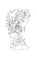
モジュール型関節窩アセンブリー10が本発明に従って提供される。図1は肩甲骨18の関節窩表面16と上腕骨部品24の頭部22との間に配置された関節窩アセンブリー10を示す図である。関節窩アセンブリー10は天然の関節窩表面を置換するために肩甲骨18の関節窩表面16に取付けられるように設計されている。関節窩アセンブリー10は第一コネクター部分を備えたベース12と、軸26に沿ってベース12の第一コネクター部分により上方28に摺動可能に収容される第二コネクター部分を備えた支持インサート14とを備えている。第一コネクター部分および第二コネクター部分は、インサート14を移動してベース12と係合させた時にインサート14をベース12に固定するように整合して係合可能である。従って関節窩アセンブリー10は回旋腱板と三角筋(図示せず)による生理的負荷に耐える。
【0008】
モジュール型関節窩アセンブリー10のベース12は、インサート14に面するように配置された凹上面30と関節窩表面16に面するように配置された凸下面32とを有する本体29を備えるように形成される。図1を参照する。上方、下方および中央の各取付けくぎ(peg)40,42,44は、下面32から延出して形成され、本体29を関節窩表面16に固定する。さらに、右安定化くぎ46と、同様に形成された左安定化くぎ(図示せず)とが下面32から延出している。
【0009】
取付けくぎ40,42,44は図1に示したように各々概ね円柱状本体部分48と概ね円錐状先端部分50で構成されている。安定化くぎ46も概ね円柱状本体部分52と概ね円錐状先端部分54で構成されている。関節窩表面16は、それぞれ取付けくぎ40,42,44および安定化くぎ46を収容するように整合された穴60を有するように形成されている。先端部分50,54により、くぎ40,42,44,46が関節窩表面16の穴60に容易に挿入される。本体部分48,52の直径は、穴60の内周にセメントマントル(図示せず)用スペースを与えるためにあるいは締まり嵌め可能とするように穴60の直径より僅かに小さい。くぎ40,42,44は本発明によれば広範な種類の形状とサイズとすることができることが分かる。
【0010】
図2に示したように、上下くぎ40,42は各々複数のノッチまたはセレーション(切り目または刻み目)62を備えるように形成されている。このセレーション62は、くぎ40,42と穴60に入れられたセメントマントル(図示せず)との間の接触面積を増やしてくぎ40,42と関節窩表面16の骨との間の接合を強化する。図1を再度参照する。図では各安定化くぎ46も、骨セメントにより安定化くぎ46が関節窩表面16の骨に固定できるようにノッチまたはセレーション62を有するように形成されている。1本または2本以上のくぎ40,42,44,46にセレーション62を形成することが本発明の範囲内にある。くぎと関節窩表面16の骨との間の接合をまた強化するために多孔質コーティングを有するくぎ40,42,44,46を備えることも本発明の範囲内にある。くぎ40,42,44,46のさらに詳細な説明は、参考文献として本明細書に含まれるFrederick A. Matsen, IIIに与えられた「関節窩構成部品(Glenoid Component)」と題する米国特許第5,032,132号に見出すことができる。くぎ40,42,44,46を図示し説明しているが、ベース12と肩甲骨18とを連結するために広範囲な取付け機構を使用することは本発明の開示の範囲内にある。
【0011】
ここで図1を参照する。ベース12の本体29の上面30は支持インサート14との摺動係合用に形成される。上面30は上方端部64、下方端部66、これら上方端部64および下方端部66間にあるように配置された中央部68、および周縁端面72を備える。さらに第一コネクター部分または外リップ70は、上方端部64および中央部68に隣接した周縁端面72から延在している。図2および図3に示したように、外リップ70は上面30から延出する側壁73と、上面30の上を側壁73から延出するタブ75とで構成され、溝74を画定する。タブ75はインサート14(図3参照)に面するテーパー面77を有する。溝74は上面30およびリップ70で画定され下方内側に開口部分を備える。溝74は概ねU字形であり、上述のように周縁端面72の周囲の一部分だけを延在しているため、ベース12の下方端部66はリップ70から離間している。
【0012】
図2に示したように上面30の中央部68はさらに凹部80を備えるように形成されている。凹部80は支持インサート14と協働して外科医にスナップ嵌めの感触を与える。上面30内に広範な種類の形状とパターンに凹部80を形成することは本発明の開示の範囲内にあるが、この凹部80は概ね形状が卵形である。あるいは、凹部を形成しないで上面を形成したり、2個以上の凹部を上面に形成したり、またはインサートの凹部(図示せず)と協働する移動止め(図示せず)を上面に形成することも本発明の開示の範囲内にある。ベース12はチタン合金のような金属から構成されるが、コバルトクロム合金およびステンレス鋼のような広範囲な金属からベースを形成することは本発明の開示の範囲内にある。さらにベース12は高度に研磨されることが好ましい。
【0013】
支持インサート14はベース12と摺動係合可能に形成され、頭部22に対して支持面20になる。図1に示したように、支持インサート14は頭部22に面する凹上面82と反対側の凸下面84とを有する。このインサート14の上面82は図2,図4および図5に示すように上腕骨部品24の頭部22に対して支持面20となる。上面82は上方端部102、下方端部104、これら上方端部102および下方端部104間にあるように配置された中央部106で構成される。インサート周縁端面108が上面82と下面84との間に延在している。周縁端面108は中に溝90を有するように構成されている。溝90は上方端部102と中央部106に隣接した周縁端面108に延在しており、リップ70のタブ75を中に収容するサイズになっている。図3に示したように、溝90は底面101、上面111および側壁113によって画定される。溝90は概ねU字形であり、上述のように周縁端面108の周囲の一部分だけを延在しているため、下方端部104は溝90から離間している。組み立てると、溝90および溝74は互いに一般的に積層整合状態に配置される。
【0014】
図3に示したように、インサート14の下面84は組み立てるとベース12の上面30に載る。下面84は上方端部105、下方端部103、およびこれら上方端部105および下方端部103間にあるように配置された中央部109を備える。図4を参照する。下面84はまた、溝74に延出してリップ70と上面30とに係合する第二コネクター部分またはタブ88を備えるように形成される。タブ88は溝90に隣接した下面84の上方端部105と中央部109の周囲に延在する。タブ88は上端部94と底端部95を下面84の下方端部103に有している。従ってタブ88は、溝74の下方内側に延在する部分にそれぞれ収容される上方外側に延在する部分を有する。
【0015】
ベース12とインサート14を組み立てるとインサート14の下面84はベース12の上面30に載る。インサート14はまた下面84の中央部109から延出する移動止め92を有する。この移動止め92は凹部80と協働してスナップ嵌めアセンブリーの感触を与える。移動止め92は形状が方形であるが、1個より多いまたは少ない任意の形状またはサイズで移動止め92を形成したり、またはベース12の対応する移動止め(図示せず)と相互作用する凹部(図示せず)を備えるように下面84を形成することも、本発明の開示の範囲内にある。インサート14は超高分子量ポリエチレン(UHMWPE)で構成されるが、整形外科用途に適切な広範な種類の材料からインサート14を製造することも本発明の範囲内にある。
【0016】
関節窩アセンブリー10を組み立てる際に、図1に示すように軸26に沿って上向きまたは上方28にインサート14を移動させる。タブ88が先ず上面30の下方端部66と係合する。インサート14がベース12に対して軸26に沿って方向28に摺動すると、タブ88が図2および図3に示したようにベース12の溝74内に収容される。さらに、インサート14の下面84のタブ88がベース12の溝74内に収容され、ベース12の外リップ70のタブ75がインサート14の溝90内に収容される。
【0017】
インサート14のタブ88は、タブ88の上端部94が上方端部64に隣接するリップ70の側壁73に係合するまで溝74内に方向28に移動する。移動止め92がベース12の凹部80に収容されるように形成されており、組み立て時に移動止め92が凹部80と「スナップ」係合し、外科医にインサート14がベース12に取付けられたことを知らせる。上方端部64の外リップ70の側壁73はタブ88の上端部94のストッパー(移動止め)としても機能する。図2および図3に示したようにインサート14をベース12に取付けると、支持面20は上腕骨部品24の頭部22に係合する態勢となっている。凹部80内に移動止め92をより簡単にガイドするため移動止め92が摺動する上面30に傾斜路またはランプ(図示せず)を備えることも本発明の範囲内にある。
【0018】
肩甲骨18の関節窩表面16内に埋め込まれると関節窩アセンブリー10は回旋腱板筋(図示せず)と三角筋(図示せず)からの負荷力を受ける。図2に示すように、これらの負荷力は上方97に向いている。関節窩アセンブリー10は図1に示したように前方/上方98または後方/下方99の力も受けるが、関節窩アセンブリー10に対する概ね上方97への負荷のため、インサート14はベース12との係合解除が防止される。
【0019】
本発明に従う別の実施形態の関節窩アセンブリー110を図5および図6に示す。関節窩アセンブリー110は、支持インサート14を軸121に沿って上方123に摺動して収容するベース112を備えている。ベース112はベース12と同様に形成される。同様の参照符号は同様の部品を示すために使用する。ベース112は中央部68に隣接して下面32から延出する取付けくぎ144を有する。くぎ144はくぎ40,42,44と同様に形成される。しかしながら、くぎ144は本発明によれば種々の形状とサイズで形成できることが分かる。くぎ144は関節窩表面16に前もって形成された穴60に収容される。図5に示したように、本体29には対応するねじ122を受けるサイズの2個の貫通穴120がある。図6に示すように完全に組み立てられると、ねじ122は穴120を通して関節窩表面16の予め形成された穴160に延在する。従ってねじ122はくぎ144と協働して肩甲骨18の関節窩表面16にベース112を連結する。ベース112はベース12と同様の材料で構成される。
【0020】
関節窩アセンブリー110の組み立て方法は関節窩アセンブリー10について前に説明した組み立て方法と同様である。インサート14は、下面84のタブ88がベース112の溝74内に収容されるように上下軸121に沿って方向123に摺動する。この時点でリップ70のタブ75がインサート14の溝90内に収容される。移動止め92と凹部80によりスナップ嵌め感触になった時にインサート14がベース112内に収容されたことが外科医に分かる。
【0021】
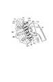
本発明の別の実施形態を図7乃至図10に示す。図7に示すように関節窩アセンブリー210はベース212と支持インサート214を備える。関節窩アセンブリー210のベース212はベース112と同様に関節窩表面16に連結されている。ベース212は関節窩表面16との係合のために形成された下面232と、概ね平らな上面230とを有する本体229を備えている。上面230は上方端部264、下方端部266、および上方端部264および下方端部266間にあるように配置された中央部268を備える。外リップ270は上方端部264と中央部268の周囲を上面230から延在している。リップ270は前に説明したようにベース12のリップ70と同様に構成され、内部に溝274を備えている。溝274は概ねU字形であり、溝74と同様に形成される。さらに、図7に示したようにベース212の上面230はその面に凹部280を有するように形成される。この凹部280は凹部80と類似しており、インサート214と協働して前に説明したようにスナップ嵌め感触を生み出す。
【0022】
ここで図8を参照する。図において本体229は離間した貫通ねじ穴320を有する。ねじ穴320は下面232と上面230との間に延在し、取付けくぎ244を中心として離間している。ねじ穴320はねじ(図示せず)が貫通延在できるサイズになっている。ベース212に2つのねじ穴320より多くまたは少なくねじ穴を設けて形成することは本開示の範囲内にある。くぎ244はベース212の下面232から延出しており、関節窩表面16内の予め形成された穴60(図5参照)内に収容されるように形成される。ねじ(図示せず)はベース212の穴320を通して関節窩表面16に形成された穴160(図5参照)に延出する。
【0023】
ここで図9および図10を参照する。図では支持インサート214が前に説明したようにインサート14と同様に頭部22と協働する。インサート214は概ね平らな下面284と、反対側の凹上面282とを有する。上面282は前に説明したように上面82と同様に形成される。下面284は上方端部203、下方端部205およびこれら上方端部203および下方端部205間にあるように配置された中央部209を有する。タブ288は下面284に形成される。図9に示したようにタブ288は上端部294および底端部295を有する。
【0024】
関節窩アセンブリー210の組み立て方法は関節窩アセンブリー10,110に関して前に説明した方法と同様である。すなわち、インサート214は、タブ288がベース112の溝274内に収容されるように上下軸221に沿って方向223に摺動する。この時点でリップ270がインサート214の溝290内に収容される。移動止め292とベース212の凹部280によりスナップ嵌め感触になった時にインサート214がベース212内に収容されたことが外科医に分かる。
【0025】
関節窩アセンブリー10,110,210を肩甲骨18に連結するため、外科医は以下の手順を踏む。よく知られた外科手順で肩甲骨18をサイズ測定し、リーマー仕上げする。それぞれベース12,112,212へのくぎに対応するように少なくとも1つの穴60を関節窩表面16にドリルで開ける。下方に開いた溝74,274を有するベース12,112,212を肩甲骨18に埋め込む。それからインサート14,14,214をそれぞれのベース12,112,212に下方から上方に摺動させる。従って、本発明のロック機構は溝内舌(tongue-in-groove)またはスロット内タブデザイン(tab-in-slot)を利用するものである。金属ベース12,112,212を関節窩18に確実に固定したら、インサート14,14,214が下方から上方に摺動するように金属ベース12,112,212を配向する。
【0026】
本発明はある好ましい実施形態に関して詳細に説明したが、様々な変形と変更が本発明の範囲と趣旨内で可能である。
【0027】
本発明の具体的な実施態様は以下の通りである。
(A)第一コネクター部分を備えており、関節窩表面と連結するように適合されたベースと、
第二コネクター部分を備えており、上腕骨の頭部に係合するように適合された支持面を備える支持インサートとを具備し、
前記第一コネクター部分および第二コネクター部分は、前記インサートを移動して前記ベースと係合させた時に、前記インサートを前記ベースに固定するように整合して係合可能であるモジュール型関節窩アセンブリー。
(1)前記第一コネクター部分は前記ベースの一部分の周囲に延在する溝を備え、前記第二コネクター部分は前記溝と係合してその中に収容されるように前記インサートの一部分の周囲に延在するタブを備える実施態様(A)請求項1に記載のアセンブリー。
(2)前記第一コネクター部分は前記ベースの一部分の周囲に延在する溝を備え、前記第二コネクター部分は、前記ベースに対して前記インサートを上方に移動して配置した時に、前記溝と係合してその中に収容されるように前記インサートの一部分の周囲に延在するタブを備える実施態様(A)に記載のアセンブリー。
(3)前記溝は下方内側に開口する部分を備え、前記タブは前記下方内側に延在する開口部分にそれぞれ収容されるように上方外側に延在する部分を備える実施態様(2)に記載のアセンブリー。
(4)前記ベースは凹上面を備え、前記インサートは前記ベースの凹面に整合して係合する凸下面を備える実施態様(3)に記載のアセンブリー。
(5)前記ベースは前記凹面に凹部を備え、前記インサートには前記凹部にスナップ嵌めするように前記凸面に移動止めを備える実施態様(4)に記載のアセンブリー。
【0028】
(B)肩甲骨の関節窩表面に取付けて支持面を与えるためのモジュール型関節窩アセンブリーであって、
リップを有しており、前記関節窩表面に連結するように適合されたベースと、
上腕骨部品の頭部に係合するように適合された支持面と、前記ベースに対し上方に移動して配置した時に前記リップに係合するように形成されたタブとを有する支持インサートとを具備するモジュール型関節窩アセンブリー。
(6)前記リップは前記ベースの一部分の周囲に延在する溝を画定し、前記タブは前記溝に収容される実施態様(B)に記載のアセンブリー。
(7)前記溝は概ねU字形である実施態様(6)に記載のアセンブリー。
(8)前記ベースは概ね凹上面を備え、前記インサートは前記ベースの前記上面に整合して係合する概ね凸下面を備える実施態様(B)に記載のアセンブリー。
(9)前記ベースは概ね平らな上面を備え、前記インサートは前記ベースの前記上面に整合して係合するように概ね平らな下面を備える実施態様(B)に記載のアセンブリー。
(10)前記リップは溝を画定し、前記インサートを前記ベースに対して上方に移動して配置した時に前記ベースが前記溝に収容される実施態様(B)に記載のアセンブリー。
【0029】
(C)下面、上面、前記下面から延出する少なくとも1本のくぎ、および前記上面の一部分の周囲に延在して溝を画定するリップを備える金属ベースと、
支持面、前記ベースの前記上面に面する反対側の下面、および前記下面の一部分の周囲に延在しており当該インサートを前記ベースに取付けるため前記溝内に下方から上方に収容されるタブを備えたプラスチック支持インサートを具備するモジュール型関節窩アセンブリー。
(11)前記ベースの上面は概ね平らであり、前記インサートの下面は前記ベースの上面に整合して係合するように概ね平らである実施態様(C)に記載のアセンブリー。
(12)前記ベースの上面は概ね凹状であり、前記インサートの下面は前記ベースの上面に整合して係合するように概ね凸状である実施態様(C)に記載のアセンブリー。
(13)前記溝は概ねU字形である実施態様(C)に記載のアセンブリー。
(14)前記溝は下方内側に開口する部分を備え、前記タブは前記下方内側に延在する開口部分にそれぞれ収容されるように上方外側に延在する部分を備える実施態様(C)に記載のアセンブリー。
(15)前記ベースは凹上面を備え、前記インサートは凸下面を備える実施態様(14)に記載のアセンブリー。
【0030】
(16)前記ベースの上面は凹部を備えるように形成され、前記インサートの下面は前記凹部にスナップ嵌めする移動止めを備えるように形成される実施態様(15)に記載のアセンブリー。
(17)前記ベースの上面は凹部を備えるように形成され、前記インサートの下面は前記凹部にスナップ嵌めする移動止めを備えるように形成される実施態様(14)に記載のアセンブリー。
【0031】
【発明の効果】
以上説明したように本発明のモジュール型関節窩アセンブリーによれば、ベースと支持インサートとが整合して係合可能であるので、肩甲骨の関節窩表面と上腕骨部品との間を強固にかつ容易に連結することができる。さらに、ベースと支持インサートに設けられたスナップ嵌め機構により、外科医はインサートがベース内に収容されたことを容易に感知することができる。
【図面の簡単な説明】
【図1】肩甲骨の関節窩表面と上腕骨部品との間に配置された本発明に従うモジュール型関節窩アセンブリーの分解斜視図であり、上面および下面、その下面から延出するくぎ、その上面に形成された凹部、および当該上面の一部の周囲に延在するリップを有するベースと、支持面、および前記リップに係合可能で整合するタブを有する下面を備えるように形成された支持インサートとを具備する関節窩アセンブリーを示す図である。
【図2】図1の線2−2に沿った組み立て断面図であり、関節窩表面に形成された穴に収容されたベースのくぎと、支持面を上腕骨部品と係合して配置しながらベースに取付けられた支持インサートとを示す図である。
【図3】図2の線3−3に沿った断面図であり、溝を有するベースのリップと、その溝内に収容されたインサートのタブとを示す図である。
【図4】図3の支持インサートの底面図であり、下方端部、上方端部、および中央部を有するインサートの下面と、その中央部から延出する移動止めと、インサートの上方端部および中央部の周囲に延在するタブとを示す図である。
【図5】インサートと使用するのに適切なベースの他の実施形態を示す図1と同様な図であり、上面および下面と、ベースを肩甲骨に連結させるねじを受けるために上面と下面との間に延在する2つの穴と、ベースの下面から延出するくぎと、当該上面の一部の周囲に延在するリップと、インサートの移動止めを収容するように上面に形成された凹部とを有するベースを示す図である。
【図6】図5のベースとインサートについての図2と同様の図であり、肩甲骨に収容されたくぎとねじ、および支持インサートをベースに連結するためにタブを収容する溝を有するベースのリップを示す図である。
【図7】本発明に従う他の実施形態の関節窩アセンブリーの断面図であり、概ね平らな上面と、下面と、この下面から延出する取付けくぎと、当該上面の一部の周囲に延在する外リップとを有するベースと、ベースの上面と嵌合するように構成された概ね平らな下面を有する支持インサートとを示す図である。
【図8】図7のベースの断面図であり、ベースを通して上面と下面との間に延在するねじ穴とこれら離間したねじ穴間にあるように配置されたくぎとを示す図である。
【図9】図7の支持インサートの底面図であり、下方端部、上方端部、および中央部を有するインサートの下面と、このインサートの上方端部および中央部の周囲に延在するタブを示す図である。
【図10】図9の線10−10に沿った断面図であり、概ね平らな下面を有する支持インサートを示す図である。[0001]
BACKGROUND OF THE INVENTION
The present invention relates to a prosthetic glenoid component, in particular a modular type for attaching the glenoid surface of the scapula to replace the natural shoulder socket and provide a support surface on the head of the humerus. Relates to glenoid assembly. More particularly, the present invention relates to a modular glenoid assembly with a metal backing base connected to a plastic support insert.
[0002]
SUMMARY OF THE INVENTION
In accordance with the present invention, a modular glenoid assembly is provided that includes a base adapted to couple with a glenoid surface and a support insert with a support surface adapted to engage a head of a humerus. Is done. The base is provided with a first connector part, and the insert is provided with a second connector part. Further, the first connector portion and the second connector portion are engageable in a proportional manner to secure the insert to the base when the insert is moved into engagement with the base.
[0003]
In a preferred embodiment, the first connector portion includes a groove extending around a portion of the base and the second connector portion includes a tab extending around a portion of the insert. This tab is received in engagement with the groove when the insert is moved to an upper position relative to the base. Further, the groove includes a portion that opens to the lower inner side, while the tab includes a portion that extends to the upper outer side that is received in the opening portion that extends to the lower inner side.
[0004]
Further in accordance with the present invention, there is provided a modular glenoid assembly that includes a base adapted to couple with a glenoid surface and a support insert and is attached to the glenoid of the scapula to provide a support surface. The base includes a lip, and the support insert is adapted to engage the lip when the insert is moved to an upper position relative to the base with a support surface adapted to engage the head of the humeral component. And formed tabs.
[0005]
Further in accordance with the present invention, a modular glenoid assembly comprising a metal base and a plastic support insert is provided. The metal base has a lower surface, an upper surface, at least one nail extending from the lower surface, and a lip extending around a portion of the upper surface to define a groove. The support insert has a support surface, an opposite lower surface facing the upper surface of the base, and a tab extending around a portion of the lower surface. The tab is accommodated in the groove from below to attach the insert to the base.
[0006]
Other features of the present invention will become apparent to those skilled in the art in view of the following description of the preferred embodiment, which illustrates the best mode of carrying out the invention, as will be readily apparent.
[0007]
DETAILED DESCRIPTION OF THE INVENTION
A
[0008]
The
[0009]
The
[0010]
As shown in FIG. 2, the upper and
[0011]
Reference is now made to FIG. The
[0012]
As shown in FIG. 2, the
[0013]
The
[0014]
As shown in FIG. 3, the
[0015]
When the
[0016]
In assembling the
[0017]
The
[0018]
When implanted in the
[0019]
Another embodiment of a
[0020]
The method of assembling the
[0021]
Another embodiment of the present invention is shown in FIGS. As shown in FIG. 7, the
[0022]
Reference is now made to FIG. In the figure, the
[0023]
Reference is now made to FIG. 9 and FIG. In the figure, the
[0024]
The method of assembling the
[0025]
To connect the
[0026]
Although the invention has been described in detail with reference to certain preferred embodiments, various modifications and changes can be made within the scope and spirit of the invention.
[0027]
Specific embodiments of the present invention are as follows.
(A) a base comprising a first connector portion and adapted to couple with a glenoid surface;
A support insert comprising a second connector portion and comprising a support surface adapted to engage the humeral head;
A modular glenoid assembly wherein the first connector portion and the second connector portion are alignably engageable to secure the insert to the base when the insert is moved into engagement with the base .
(1) The first connector portion includes a groove extending around a portion of the base, and the second connector portion engages the groove and is received therein. With tabs extending toEmbodiment (A)The assembly of claim 1.
(2) The first connector portion includes a groove extending around a portion of the base, and the second connector portion has the groove when the insert is moved upward relative to the base. A tab extending around a portion of the insert to engage and be received thereinEmbodiment (A)Assembly according to.
(3) The groove is a portion that opens to the lower inside.WithThe assembly according to embodiment (2), wherein the tab comprises a portion extending outwardly so as to be received in an opening portion extending downwardly inward.
(4) The assembly according to embodiment (3), wherein the base has a concave upper surface, and the insert has a convex lower surface that engages and engages the concave surface of the base.
(5) The assembly according to the embodiment (4), wherein the base includes a concave portion on the concave surface, and the insert includes a detent on the convex surface so as to snap-fit into the concave portion.
[0028]
(B) a modular glenoid assembly for attaching to the glenoid surface of the scapula to provide a support surface,
A base having a lip and adapted to couple to the glenoid surface;
A support insert having a support surface adapted to engage the head of the humeral component and a tab formed to engage the lip when moved upward relative to the base. A modular glenoid assembly comprising:
(6) The lip defines a groove extending around a portion of the base, and the tab is received in the groove.Embodiment (B)Assembly according to.
(7) The assembly according to embodiment (6), wherein the groove is generally U-shaped.
(8) The base has a generally concave upper surface, and the insert has a generally convex lower surface that aligns and engages the upper surface of the base.Embodiment (B)Assembly according to.
(9) The base has a generally flat top surface and the insert has a generally flat bottom surface to align and engage the top surface of the base.Embodiment (B)Assembly according to.
(10) The lip defines a groove, and the base is received in the groove when the insert is moved upward with respect to the base.Embodiment (B)Assembly according to.
[0029]
(C) a metal base comprising a lower surface, an upper surface, at least one nail extending from the lower surface, and a lip extending around a portion of the upper surface to define a groove;
A support surface, a lower surface opposite the upper surface of the base, and a tab that extends around a portion of the lower surface and that is received from below into the groove for mounting the insert to the base. A modular glenoid assembly comprising a plastic support insert provided.
(11) The upper surface of the base is generally flat and the lower surface of the insert is generally flat so as to align and engage the upper surface of the base.Embodiment (C)Assembly according to.
(12) The upper surface of the base is generally concave, and the lower surface of the insert is generally convex so as to align and engage with the upper surface of the base.Embodiment (C)Assembly according to.
(13) The groove is generally U-shaped.Embodiment (C)Assembly according to.
(14) The groove is a portion that opens inward and downwardWithThe tab includes a portion extending upward and outward so as to be received in the opening portion extending downward and inward, respectively.Embodiment (C)Assembly according to.
(15) The assembly according to embodiment (14), wherein the base comprises a concave upper surface and the insert comprises a convex lower surface.
[0030]
(16) The assembly according to embodiment (15), wherein the upper surface of the base is formed to have a recess, and the lower surface of the insert is formed to have a detent that snaps into the recess.
(17) The assembly according to embodiment (14), wherein the upper surface of the base is formed with a recess, and the lower surface of the insert is formed with a detent that snaps into the recess.
[0031]
【The invention's effect】
As described above, according to the modular glenoid assembly of the present invention, the base and the support insert can be aligned and engaged, so that the glenoid surface of the scapula and the humerus component can be firmly Can be easily connected. Furthermore, a snap-fit mechanism provided on the base and support insert allows the surgeon to easily sense that the insert has been received within the base.
[Brief description of the drawings]
FIG. 1 is an exploded perspective view of a modular glenoid assembly according to the present invention placed between a glenoid surface of a scapula and a humeral component, the upper and lower surfaces, a nail extending from the lower surface, the upper surface thereof And a support insert formed to include a base having a recess formed in the upper surface and a lip extending around a portion of the upper surface; a support surface; and a lower surface having a tab engageable and aligned with the lip. FIG.
2 is an assembled cross-sectional view taken along line 2-2 in FIG. 1, with the base nail received in the hole formed in the glenoid surface and the support surface in engagement with the humeral component; It is a figure which shows the support insert attached to the base, however.
3 is a cross-sectional view taken along line 3-3 of FIG. 2, showing the lip of the base having a groove and the tab of the insert housed in the groove.
4 is a bottom view of the support insert of FIG. 3, with the lower surface of the insert having a lower end, an upper end, and a central portion, a detent extending from the central portion, the upper end of the insert, and FIG. It is a figure which shows the tab extended around the center part.
FIG. 5 is a view similar to FIG. 1 illustrating another embodiment of a base suitable for use with an insert, the top and bottom surfaces, and the top and bottom surfaces for receiving screws that connect the base to the scapula; A recess extending in the upper surface to accommodate a detent extending from the lower surface of the base, a nail extending from the lower surface of the base, a lip extending around a portion of the upper surface, and a detent of the insert. It is a figure which shows the base which has.
6 is a view similar to FIG. 2 of the base and insert of FIG. 5, with a nail and screw housed in the scapula, and a base having a groove for receiving a tab to connect the support insert to the base. It is a figure which shows a lip.
FIG. 7 is a cross-sectional view of another embodiment of a glenoid assembly in accordance with the present invention, a generally flat top surface, a bottom surface, a mounting nail extending from the bottom surface, and extending around a portion of the top surface. FIG. 5 shows a base having an outer lip that supports and a support insert having a generally flat lower surface configured to mate with an upper surface of the base.
8 is a cross-sectional view of the base of FIG. 7, showing a threaded hole extending through the base between the top and bottom surfaces and a nail positioned to be between these spaced threaded holes.
FIG. 9 is a bottom view of the support insert of FIG. 7 with the bottom surface of the insert having a lower end, an upper end, and a central portion and tabs extending around the upper end and the central portion of the insert; FIG.
10 is a cross-sectional view taken along line 10-10 of FIG. 9, showing a support insert having a generally flat lower surface.
Claims (2)
Translated fromJapaneseベースであって、
(i)前記関節窩表面と係合するよう構成された下面と、
(ii)上面と、
(iii)上方端部と、
(iv)下方端部と、
(v)中央部と、
(vi)周縁端面と、
(vii)溝を画定し、前記上方端部において前記周縁端面の一部分の周囲に延在するリップと
を有するベースと、
支持インサートであって、
(i)上腕骨部品の頭部に摺動可能に係合するよう構成された支持面と、
(ii)前記ベースの前記上面に面する反対側の下面と、
(iii)前記ベースに対し前記支持インサートを移動して配置した時に、前記リップの前記溝に係合するように形成されたタブと
を含む支持インサートと
を備え、
前記リップおよび前記溝は双方とも概ねU字形であり、
前記ベースの前記上面は凹部を備えるように形成され、前記支持インサートの前記下面は前記凹部にスナップ嵌めする移動止めを備えるように形成される、モジュール型関節窩アセンブリー。In a modular glenoid assembly for attaching to the glenoid surface of the scapula to provide a support surface,
The base,
(I) a lower surface configured to engage the glenoid surface;
(Ii) an upper surface;
(Iii) an upper end;
(Iv) a lower end;
(V) a central portion;
(vi) a peripheral edge surface;
(vii) a base having a lip defining a groove and extending around a portion of the peripheral end face at the upper end;
A support insert,
(I) a support surface configured to slidably engage the head of the humeral component;
(Ii) a lower surface opposite to the upper surface of the base;
(Iii) a support insert including: a tab formed to engage the groove of the lip when the support insert is moved and arranged relative to the base;
The lip and the groove are both generally U-shaped,
A modular glenoid assembly wherein the upper surface of the base is formed with a recess and the lower surface of the support insert is formed with a detent that snaps into the recess.
下面、上面、下方端部、上方端部、中央部、周縁端面、前記下面から延出する少なくとも1本のくぎ、および前記上方端部において前記周縁端面の一部分の周囲に延在して溝を画定するリップ、を含む金属ベースと、
プラスチック支持インサートであって、上腕骨部品の頭部に摺動可能に係合するよう構成された支持面と、前記ベースの前記上面に面する反対側の下面と、前記下面の一部分の周囲に延在し前記溝内に第一の方向から第二の方向に向けて収容されて前記プラスチック支持インサートを前記ベースに取付けるタブとを含む、プラスチック支持インサートと
を備え、
前記リップおよび前記溝は双方とも概ねU字形であり、
前記ベースの前記上面は凹部を備えるように形成され、前記支持インサートの前記下面は前記凹部にスナップ嵌めする移動止めを備えるように形成される、モジュール型関節窩アセンブリー。In a modular glenoid assembly,
A lower surface, an upper surface, a lower end portion, an upper end portion, a central portion, a peripheral end surface, at least one nail extending from the lower surface, and a groove extending around a portion of the peripheral end surface at the upper end portion A metal base including a defining lip;
A plastic support insert , wherein the support surface is configured to slidably engage the head of the humeral component, an opposite lower surface facing the upper surface of the base, and around a portion of the lower surface. from extending Mashimashi first direction in the groove is accommodated in a second direction anda tab for mounting saidplastic bearing insert to saidbase, and a plastic bearing insert,
The lip and the groove are both generally U-shaped,
A modular glenoid assembly wherein the upper surface of the base is formed with a recess and the lower surface of the support insert is formed with a detent that snaps into the recess.
Applications Claiming Priority (4)
| Application Number | Priority Date | Filing Date | Title |
|---|---|---|---|
| US8859498P | 1998-06-09 | 1998-06-09 | |
| US9475798P | 1998-07-31 | 1998-07-31 | |
| US088594 | 1998-07-31 | ||
| US094757 | 1998-07-31 |
Publications (2)
| Publication Number | Publication Date |
|---|---|
| JP2000005205A JP2000005205A (en) | 2000-01-11 |
| JP4282826B2true JP4282826B2 (en) | 2009-06-24 |
Family
ID=26778839
Family Applications (1)
| Application Number | Title | Priority Date | Filing Date |
|---|---|---|---|
| JP16133599AExpired - Fee RelatedJP4282826B2 (en) | 1998-06-09 | 1999-06-08 | Modular glenoid assembly |
Country Status (4)
| Country | Link |
|---|---|
| US (2) | US6228119B1 (en) |
| EP (1) | EP0963742B1 (en) |
| JP (1) | JP4282826B2 (en) |
| DE (1) | DE69921546T2 (en) |
Families Citing this family (143)
| Publication number | Priority date | Publication date | Assignee | Title |
|---|---|---|---|---|
| US6494913B1 (en) | 1998-03-17 | 2002-12-17 | Acumed, Inc. | Shoulder prosthesis |
| US6228119B1 (en)* | 1998-06-09 | 2001-05-08 | Depuy Orthopaedics, Inc. | Modular glenoid assembly |
| US6911047B2 (en)* | 2000-03-17 | 2005-06-28 | Depuy Orthopaedics, Inc. | Apparatus and method for securing a cementless glenoid component to a glenoid surface of a scapula |
| US6610067B2 (en) | 2000-05-01 | 2003-08-26 | Arthrosurface, Incorporated | System and method for joint resurface repair |
| US6589281B2 (en) | 2001-01-16 | 2003-07-08 | Edward R. Hyde, Jr. | Transosseous core approach and instrumentation for joint replacement and repair |
| US6569202B2 (en)* | 2001-04-02 | 2003-05-27 | Whiteside Biomechanics, Inc. | Tray and liner for joint replacement system |
| FR2825263A1 (en)* | 2001-05-30 | 2002-12-06 | Tecknimed | Shoulder joint prosthesis has cap on humerus to engage socket with movement limiting stop surfaces |
| US7892288B2 (en) | 2001-08-27 | 2011-02-22 | Zimmer Technology, Inc. | Femoral augments for use with knee joint prosthesis |
| US20030065397A1 (en) | 2001-08-27 | 2003-04-03 | Hanssen Arlen D. | Prosthetic implant support structure |
| US20030055507A1 (en)* | 2001-09-11 | 2003-03-20 | Incumed, Incorporated | Modular prosthesis and insertion tool for bone structures |
| US6676705B1 (en) | 2001-09-13 | 2004-01-13 | Eugene M. Wolf | Variable tilt angle taper lock shoulder prosthesis |
| US6699289B2 (en)* | 2001-12-31 | 2004-03-02 | Depuy Orthopaedics, Inc. | Augmented glenoid component having an interrupted surface and associated method for securing the augmented glenoid component to a glenoid surface of a scapula |
| FR2843293B1 (en)* | 2002-08-08 | 2005-07-01 | Didier Capon | PROTHETIC IMPLANT FOR THE JOINT OF AN ANATOMIC MEMBER |
| US7204854B2 (en)* | 2002-08-15 | 2007-04-17 | Arthrex, Inc. | Metal back prosthetic glenoid component with cemented pegs and hollow metal cage screw |
| US7452381B2 (en)* | 2003-01-30 | 2008-11-18 | Mayo Foundation For Medical Education And Research | Radial head replacement system |
| US8388624B2 (en) | 2003-02-24 | 2013-03-05 | Arthrosurface Incorporated | Trochlear resurfacing system and method |
| US7887544B2 (en)* | 2003-03-10 | 2011-02-15 | Tornier Sas | Ancillary tool for positioning a glenoid implant |
| US7625408B2 (en)* | 2003-07-22 | 2009-12-01 | Avanta Orthopaedics, Llc | Prosthetic wrist implant |
| US20050043805A1 (en)* | 2003-08-11 | 2005-02-24 | Chudik Steven C. | Devices and methods used for shoulder replacement |
| FR2859099B1 (en)* | 2003-08-25 | 2006-01-06 | Tornier Sa | GLENOIDAL COMPONENT OF SHOULDER PROSTHESIS AND TOTAL SHOULDER PROSTHESIS INCORPORATING SUCH COMPONENT |
| GB0320287D0 (en)* | 2003-08-29 | 2003-10-01 | Stanmore Implants Worldwide | Shoulder joint prosthetic system |
| FR2860426B1 (en)* | 2003-10-01 | 2006-05-26 | Biomet Merck France | GLENOID CAVITY PROSTHESIS OF SCAPULA |
| FR2863865B1 (en)* | 2003-12-19 | 2006-10-06 | Tornier Sa | SHOULDER OR HIP PROSTHESIS AND METHOD OF MOUNTING |
| US7294133B2 (en)* | 2004-06-03 | 2007-11-13 | Zimmer Technology, Inc. | Method and apparatus for preparing a glenoid surface |
| FR2871371B1 (en)* | 2004-06-15 | 2007-04-06 | Tornier Sas | GLENOIDAL COMPONENT OF SHOULDER PROSTHESIS, SET OF COMPONENT ELEMENTS OF SUCH COMPONENT AND TOTAL SHOULDER PROSTHESIS INCORPORATING SUCH COMPONENT |
| US8303665B2 (en) | 2004-06-15 | 2012-11-06 | Tornier Sas | Glenoidal component, set of such components and shoulder prosthesis incorporating such a glenoidal component |
| US7678150B2 (en)* | 2004-06-15 | 2010-03-16 | Tornier Sas | Total shoulder prosthesis of an inverted type |
| FR2872025B1 (en) | 2004-06-28 | 2006-08-25 | Tornier Sas | PROSTHESIS OF SHOULDER OR HIP |
| WO2006004885A2 (en) | 2004-06-28 | 2006-01-12 | Arthrosurface, Inc. | System for articular surface replacement |
| US7927335B2 (en) | 2004-09-27 | 2011-04-19 | Depuy Products, Inc. | Instrument for preparing an implant support surface and associated method |
| US7922769B2 (en)* | 2004-09-27 | 2011-04-12 | Depuy Products, Inc. | Modular glenoid prosthesis and associated method |
| US7892287B2 (en)* | 2004-09-27 | 2011-02-22 | Depuy Products, Inc. | Glenoid augment and associated method |
| US20060074353A1 (en)* | 2004-09-27 | 2006-04-06 | Deffenbaugh Daren L | Glenoid instrumentation and associated method |
| US20060079963A1 (en)* | 2004-10-07 | 2006-04-13 | Regan Hansen | Semiconstrained shoulder prosthetic for treatment of rotator cuff arthropathy |
| US7160331B2 (en) | 2004-12-01 | 2007-01-09 | Mayo Foundation For Medical Research And Education | Sigmoid notch implant |
| EP1848377A4 (en)* | 2005-02-11 | 2009-12-30 | Brigham & Womens Hospital | SHOULDERARTHROPLASTY DEVICE AND METHOD |
| US20230080207A1 (en) | 2005-02-25 | 2023-03-16 | Shoulder Innovations, Inc. | Methods and devices for less invasive glenoid replacement |
| US8778028B2 (en) | 2005-02-25 | 2014-07-15 | Shoulder Innovations, Inc. | Methods and devices for less invasive glenoid replacement |
| US8007538B2 (en)* | 2005-02-25 | 2011-08-30 | Shoulder Innovations, Llc | Shoulder implant for glenoid replacement |
| US20060200248A1 (en)* | 2005-03-03 | 2006-09-07 | Laurent Beguin | Prosthesis for the glenoid cavity of the scapula |
| US20070055380A1 (en)* | 2005-09-08 | 2007-03-08 | Biomet Manufacturing Corp | Method and apparatus for a glenoid prosthesis |
| GB2431354A (en)* | 2005-10-24 | 2007-04-25 | Benoist Girard Sas | A prosthetic glenoid component with soft bearing surface |
| EP1940322A2 (en)* | 2005-10-26 | 2008-07-09 | Exactech, Inc. | Apparatus and method to obtain bone fixation |
| ITUD20050185A1 (en)* | 2005-11-03 | 2007-05-04 | Lima Lto Spa | ADDITIONAL FIXING ELEMENT FOR A PROSTHESIS FOR THE ARTICULATION OF THE SHOULDER |
| CN103239304B (en)* | 2005-11-07 | 2015-09-30 | 精密技术公司 | For installing prosthese on the bone of a patient |
| US7753959B2 (en) | 2006-03-20 | 2010-07-13 | Biomet Manufacturing Corp. | Modular center pegged glenoid |
| US8425614B2 (en)* | 2006-03-20 | 2013-04-23 | Biomet Manufacturing Corp. | Modular center pegged glenoid |
| WO2007109319A2 (en)* | 2006-03-21 | 2007-09-27 | Axiom Orthopaedics, Inc. | Glenoid component with improved fixation stability |
| EP1996123B1 (en)* | 2006-03-21 | 2019-08-28 | Tornier, Inc. | Non-spherical articulating surfaces in shoulder and hip prosthesis |
| WO2007109340A2 (en)* | 2006-03-21 | 2007-09-27 | Axiom Orthopaedics, Inc. | Femoral and humeral stem geometry and implantation method for orthopedic joint reconstruction |
| JP5180953B2 (en) | 2006-03-23 | 2013-04-10 | イグザクテック・インコーポレイテッド | Reverse shoulder glenoid plate and prosthesis |
| FR2899790B1 (en)* | 2006-04-13 | 2008-06-13 | Tornier Sas | GLENOIDAL COMPONENT FOR TOTAL SHOULDER PROSTHESIS, SET OF SUCH COMPONENTS, AND TOTAL SHOULDER PROSTHESIS COMPRISING SUCH A COMPONENT |
| FR2900045B1 (en)* | 2006-04-21 | 2009-01-16 | Tornier Sas | PROSTHESIS OF SHOULDER OR HIP |
| PL1854431T3 (en)* | 2006-05-12 | 2010-05-31 | Synthes Gmbh | Joint endoprosthesis |
| US20080021564A1 (en)* | 2006-07-20 | 2008-01-24 | Gunther Stephen B | Humeral head resurfacing implant and methods of use thereof |
| US9358029B2 (en) | 2006-12-11 | 2016-06-07 | Arthrosurface Incorporated | Retrograde resection apparatus and method |
| US20090287309A1 (en) | 2007-01-30 | 2009-11-19 | Tornier Sas | Intra-articular joint replacement |
| FR2911773B1 (en) | 2007-01-30 | 2009-03-27 | Tornier Sas | METHOD AND ASSEMBLY OF SURGICAL INSTRUMENTATION FOR POSITIONING A TOTAL REVERSE SHOULDER PROSTHESIS, AND CORRESPONDING PROSTHESIS |
| WO2008098250A2 (en)* | 2007-02-10 | 2008-08-14 | Small Bone Innovations, Inc. | Radial head implant and related instrument |
| ES2397225T3 (en) | 2007-04-20 | 2013-03-05 | Woodwelding Ag | Implant system to attach an implant to bone tissue |
| US8157866B2 (en) | 2007-11-05 | 2012-04-17 | Biomet Manufacturing Corp. | Method and apparatus for performing a less invasive shoulder procedure |
| EP2057970B1 (en)* | 2007-11-07 | 2016-01-06 | Arthrex, Inc. | Hybrid glenoid for shoulder arthroplasty |
| DE102008021110A1 (en)* | 2008-04-28 | 2009-10-29 | Smith & Nephew Orthopaedics Ag | Scapular component of a shoulder joint prosthesis |
| US8241365B2 (en)* | 2008-12-23 | 2012-08-14 | Depuy Products, Inc. | Shoulder prosthesis with vault-filling structure having bone-sparing configuration |
| US20100161066A1 (en)* | 2008-12-23 | 2010-06-24 | Depuy Products, Inc. | Shoulder Prosthesis having Augmented Metaglene Component for Use in Rotator Cuff Deficient Shoulder |
| US8632597B2 (en) | 2008-12-23 | 2014-01-21 | DePuy Synthes Products, LLC | Rotatable reverse metaglene |
| US9545311B2 (en) | 2009-03-05 | 2017-01-17 | Tornier, Inc. | Glenoid implant anchor post |
| US9833327B2 (en)* | 2009-03-20 | 2017-12-05 | DePuy Synthes Products, Inc. | Glenoid component for use in shoulder arthroplasty |
| US10945743B2 (en) | 2009-04-17 | 2021-03-16 | Arthrosurface Incorporated | Glenoid repair system and methods of use thereof |
| WO2010121250A1 (en) | 2009-04-17 | 2010-10-21 | Arthrosurface Incorporated | Glenoid resurfacing system and method |
| AU2010236182A1 (en) | 2009-04-17 | 2011-11-24 | Arthrosurface Incorporated | Glenoid resurfacing system and method |
| US9549820B2 (en)* | 2009-06-25 | 2017-01-24 | Zimmer, Inc. | Glenoid implant with synthetic labrum |
| US8231683B2 (en) | 2009-12-08 | 2012-07-31 | Depuy Products, Inc. | Shoulder prosthesis assembly having glenoid rim replacement structure |
| FR2955247B1 (en) | 2010-01-21 | 2013-04-26 | Tornier Sa | GLENOIDAL COMPONENT OF SHOULDER PROSTHESIS |
| US9517139B2 (en) | 2010-01-15 | 2016-12-13 | DePuy Synthes Products, Inc. | Acromion spacer |
| EP2542165A4 (en) | 2010-03-05 | 2015-10-07 | Arthrosurface Inc | Tibial resurfacing system and method |
| US9408652B2 (en) | 2010-04-27 | 2016-08-09 | Tornier Sas | Intra-articular joint replacement and method |
| EP2575689A2 (en)* | 2010-05-26 | 2013-04-10 | Topsfield Medical GmbH | Implantable prostheses |
| US9320608B2 (en) | 2010-09-01 | 2016-04-26 | Mayo Foundation For Medical Education And Research | Method for optimization of joint arthroplasty component design |
| JP2014504161A (en) | 2010-09-01 | 2014-02-20 | メイヨ フォンデーシヨン フォー メディカル エジュケーション アンド リサーチ | Method for optimizing arthroplasty component design |
| FR2966343B1 (en) | 2010-10-22 | 2012-12-07 | Tornier Sa | SET OF GLENOIDIAN COMPONENTS OF SHOULDER PROSTHESIS |
| FR2967046A1 (en) | 2010-11-10 | 2012-05-11 | Tornier Sa | ORTHOPEDIC BONE PREPARATION MACHINE, ESPECIALLY GLENOIDIAN PREPARATION |
| US8480750B2 (en) | 2010-11-24 | 2013-07-09 | DePuy Synthes Products, LLC | Modular glenoid prosthesis |
| US8465548B2 (en)* | 2010-11-24 | 2013-06-18 | DePuy Synthes Products, LLC | Modular glenoid prosthesis |
| FR2971144A1 (en)* | 2011-02-08 | 2012-08-10 | Tornier Sa | GLENOIDAL IMPLANT FOR SHOULDER PROSTHESIS AND SURGICAL KIT |
| US20120253467A1 (en) | 2011-02-13 | 2012-10-04 | Mark Frankle | Shoulder Arthroplasty Systems and Configurations for Components Thereof |
| WO2012154920A1 (en) | 2011-05-12 | 2012-11-15 | Small Bone Innovations, Inc. | Wrist implant for carpal hemiarthroplasty |
| US20130018476A1 (en) | 2011-07-13 | 2013-01-17 | Biomet Manufacturing Corp. | Shoulder prosthesis |
| US8506638B2 (en) | 2011-07-13 | 2013-08-13 | Biomets Manufacturing, LLC | Shoulder prosthesis |
| EP2586387A1 (en) | 2011-10-31 | 2013-05-01 | Tornier Orthopedics Ireland Ltd. | Bone reamer |
| US8449617B1 (en) | 2011-11-16 | 2013-05-28 | Biomet Manufacturing Corp. | Convertible glenoid implant |
| US9421106B2 (en) | 2011-12-07 | 2016-08-23 | Howmedica Osteonics Corp. | Reverse shoulder baseplate with alignment guide for glenosphere |
| US9414927B2 (en) | 2011-12-08 | 2016-08-16 | Imds Llc | Shoulder arthroplasty |
| US9439768B2 (en) | 2011-12-08 | 2016-09-13 | Imds Llc | Glenoid vault fixation |
| EP2804565B1 (en) | 2011-12-22 | 2018-03-07 | Arthrosurface Incorporated | System for bone fixation |
| US8998994B2 (en) | 2012-02-07 | 2015-04-07 | Biomet Manufacturing, Llc | Humeral implant having a floating bearing |
| US9248022B2 (en) | 2012-03-27 | 2016-02-02 | DePuy Synthes Products, Inc. | Method of implanting a glenoid defect-filling component |
| US9498334B2 (en) | 2012-03-27 | 2016-11-22 | DePuy Synthes Products, Inc. | Glenoid defect-filling component |
| CN106667543B (en) | 2012-03-30 | 2020-09-01 | 德普伊新特斯产品有限责任公司 | Stemless humeral component and associated surgical instrument and method |
| US8906102B2 (en)* | 2012-05-31 | 2014-12-09 | Howmedica Osteonics Corp. | Lateral entry insert for cup trial |
| US8663334B2 (en)* | 2012-05-31 | 2014-03-04 | Howmedica Osteonics Corp. | Lateral entry insert for cup trial |
| WO2014008126A1 (en) | 2012-07-03 | 2014-01-09 | Arthrosurface Incorporated | System and method for joint resurfacing and repair |
| BR112015007174A8 (en) | 2012-10-29 | 2018-04-24 | Tornier Orthopedics Ireland Ltd | Modular reverse shoulder prosthesis and respective systems |
| US20140128985A1 (en)* | 2012-11-07 | 2014-05-08 | Roy W. Sanders | Joint Arthroplasty Systems, Methods, and Components |
| US9788957B2 (en) | 2012-12-07 | 2017-10-17 | Cleveland Clinic Foundation | Glenoid vault fixation |
| US10130480B2 (en) | 2013-03-13 | 2018-11-20 | Howmedica Osteonics Corp. | Modular patella trials |
| US9492200B2 (en) | 2013-04-16 | 2016-11-15 | Arthrosurface Incorporated | Suture system and method |
| CN103230311B (en)* | 2013-05-06 | 2015-12-23 | 北京爱康宜诚医疗器材股份有限公司 | Combination type shoulder joint prosthesis |
| US9956083B2 (en) | 2013-12-30 | 2018-05-01 | Deltoid, Llc | Instruments and techniques for orienting prosthesis components for joint prostheses |
| US9962266B2 (en) | 2015-09-11 | 2018-05-08 | Deltoid, Llc | Arthroplasty components |
| US10433969B2 (en) | 2013-12-30 | 2019-10-08 | United Orthopedic Corp. | Arthroplasty implants and methods for orienting joint prosthesis |
| WO2015103090A1 (en) | 2014-01-03 | 2015-07-09 | Tornier, Inc. | Reverse shoulder systems |
| US20150190234A1 (en)* | 2014-01-06 | 2015-07-09 | Chih-Shing Wei | Midlay compartmental tibial component |
| US11607319B2 (en) | 2014-03-07 | 2023-03-21 | Arthrosurface Incorporated | System and method for repairing articular surfaces |
| US9931219B2 (en) | 2014-03-07 | 2018-04-03 | Arthrosurface Incorporated | Implant and anchor assembly |
| US10624748B2 (en) | 2014-03-07 | 2020-04-21 | Arthrosurface Incorporated | System and method for repairing articular surfaces |
| US20150272741A1 (en)* | 2014-03-26 | 2015-10-01 | Biomet Manufacturing, Llc | Press-fit glenoid with peripheral compression pegs |
| US9681960B2 (en) | 2014-05-16 | 2017-06-20 | Howmedica Osteonics Corp. | Guides for fracture system |
| US10575968B2 (en) | 2014-05-16 | 2020-03-03 | Howmedica Osteonics Corp. | Guides for fracture system |
| US11234826B2 (en)* | 2014-06-30 | 2022-02-01 | Howmedica Osteonics Corp. | Augmented glenoid components and devices for implanting the same |
| US10492926B1 (en) | 2014-09-04 | 2019-12-03 | Shoulder Innovations, Inc. | Alignment guide for humeral or femoral stem replacement prostheses |
| FR3029769A1 (en) | 2014-12-10 | 2016-06-17 | Tornier Sa | KIT FOR A PROSTHESIS OF SHOULDER |
| WO2016164385A1 (en)* | 2015-04-07 | 2016-10-13 | Zimmer, Inc. | Convertible glenoid |
| US10722374B2 (en) | 2015-05-05 | 2020-07-28 | Tornier, Inc. | Convertible glenoid implant |
| USD835276S1 (en) | 2015-09-11 | 2018-12-04 | United Orthopedic Corporation | Keeled glenoid |
| US10390972B2 (en) | 2016-01-15 | 2019-08-27 | Howmedica Osteonics Corp. | Humeral trial adaptor |
| EP3445292B1 (en) | 2016-04-19 | 2022-12-21 | Imascap SAS | Pre-operatively planned humeral implant and planning method |
| CA3051099C (en) | 2017-01-20 | 2022-07-12 | Biomet Manufacturing, Llc | Modular augment component |
| EP4520302A3 (en) | 2017-04-14 | 2025-04-16 | Shoulder Innovations, Inc. | Total shoulder prosthesis having inset glenoid implant convertible from anatomic to reverse |
| US11160663B2 (en)* | 2017-08-04 | 2021-11-02 | Arthrosurface Incorporated | Multicomponent articular surface implant |
| WO2019079104A2 (en) | 2017-10-16 | 2019-04-25 | Imascap Sas | Shoulder implants and methods of use and assembly |
| WO2019099451A2 (en)* | 2017-11-14 | 2019-05-23 | Conmed Corporation | Securing a bone graft to the glenoid bone and implementations thereof |
| US12138172B2 (en) | 2018-04-30 | 2024-11-12 | Shoulder Innovations, Inc. | Inset/onlay glenoid, porous coated convertible glenoid, and humeral heads with textured undersides |
| AU2020237088B2 (en) | 2019-03-11 | 2025-09-04 | Shoulder Innovations, Inc. | Total reverse shoulder systems and methods |
| USD977643S1 (en) | 2019-03-12 | 2023-02-07 | Shoulder Innovations, Inc. | Humeral stem implant |
| WO2020186099A1 (en) | 2019-03-12 | 2020-09-17 | Arthrosurface Incorporated | Humeral and glenoid articular surface implant systems and methods |
| KR102650843B1 (en)* | 2019-04-25 | 2024-03-22 | 앙코르 메디컬, 엘.피.(디/비/에이 디제이오 서지컬) | glenoid implant system |
| JP7257546B2 (en) | 2019-05-13 | 2023-04-13 | ハウメディカ オステオニクス コーポレイション | Glenoid baseplate and implant assembly |
| EP3982848A1 (en) | 2019-08-09 | 2022-04-20 | Howmedica Osteonics Corp. | Apparatuses and methods for implanting glenoid prostheses |
| USD938590S1 (en) | 2019-10-01 | 2021-12-14 | Howmedica Osteonics Corp. | Humeral implant |
| AU2021200854A1 (en) | 2020-03-03 | 2021-09-16 | Howmedica Osteonics Corp. | Glenoid implant with additively manufactured fixation posts |
| CN111281620B (en)* | 2020-03-30 | 2024-12-03 | 北京市春立正达医疗器械股份有限公司 | A glenoid prosthesis used in total shoulder arthroplasty |
| EP4351485A4 (en)* | 2021-08-12 | 2025-04-16 | Howmedica Osteonics Corp. | GLENOID COMPONENT WITH FENESTRATED BEARING |
Family Cites Families (17)
| Publication number | Priority date | Publication date | Assignee | Title |
|---|---|---|---|---|
| US4524467A (en)* | 1983-11-21 | 1985-06-25 | Joint Medical Products Corp. | Apparatus for constraining a socket bearing in an artificial joint |
| JPS60166316U (en)* | 1984-04-13 | 1985-11-05 | 瑞穂医科工業株式会社 | artificial shoulder joint |
| US4795468A (en)* | 1987-12-23 | 1989-01-03 | Zimmer, Inc. | Mechanism and method for locking a bearing insert to the base of a prosthetic implant |
| US4865605A (en)* | 1988-02-02 | 1989-09-12 | Dines David M | Modular shoulder prosthesis |
| US4964865A (en) | 1988-02-03 | 1990-10-23 | Intermedics Orthopedics, Inc. | Glenoid prosthesis and method of use |
| US5080673A (en) | 1988-02-03 | 1992-01-14 | Intermedics Orthopedics, Inc. | Glenoid prosthesis and method of use |
| US4986833A (en) | 1989-05-05 | 1991-01-22 | Worland Richard L | Glenoid component for an artificial shoulder joint |
| US5032132A (en)* | 1990-01-22 | 1991-07-16 | Boehringer Mannheim Corporation | Glenoid component |
| FR2683142B1 (en) | 1991-10-31 | 1995-12-15 | Deux C T | PROSTHESIS FOR HUMERAL GLENNE. |
| FR2695313B1 (en) | 1992-09-08 | 1994-10-28 | Fabrication Etu Realisa Implan | Glenoid implant. |
| DE4238832C1 (en)* | 1992-11-17 | 1994-08-11 | Plus Endoprothetik Ag | Shoulder joint endoprosthesis |
| US5593448A (en)* | 1995-11-14 | 1997-01-14 | Osteonics Corp. | Glenoid component for shoulder prosthesis and implant method |
| FR2741796B1 (en)* | 1995-11-30 | 1998-03-27 | Tornier Sa | DEVICE FOR FIXING A PROSTHESIS AND PARTICULARLY A GLENOIDAL PROSTHESIS OF OMOPLATE |
| FR2755847B1 (en) | 1996-10-11 | 1999-01-29 | Medinov Amp | PROSTHETIC ASSEMBLY FOR THE SHOULDER JOINT |
| US5800551A (en)* | 1997-03-10 | 1998-09-01 | Biomet, Inc. | Apparatus and method for shoulder arthroplasty |
| US6228119B1 (en)* | 1998-06-09 | 2001-05-08 | Depuy Orthopaedics, Inc. | Modular glenoid assembly |
| FR2780635B1 (en)* | 1998-07-06 | 2000-10-20 | Tornier Sa | DEVICE FOR FIXING A PLASTIC INSERT |
- 1999
- 1999-05-27USUS09/321,778patent/US6228119B1/ennot_activeExpired - Lifetime
- 1999-06-08DEDE69921546Tpatent/DE69921546T2/ennot_activeExpired - Lifetime
- 1999-06-08JPJP16133599Apatent/JP4282826B2/ennot_activeExpired - Fee Related
- 1999-06-08EPEP99304423Apatent/EP0963742B1/ennot_activeExpired - Lifetime
- 2001
- 2001-03-19USUS09/811,929patent/US6514287B2/ennot_activeExpired - Lifetime
Also Published As
| Publication number | Publication date |
|---|---|
| US6228119B1 (en) | 2001-05-08 |
| EP0963742B1 (en) | 2004-11-03 |
| JP2000005205A (en) | 2000-01-11 |
| US6514287B2 (en) | 2003-02-04 |
| DE69921546D1 (en) | 2004-12-09 |
| DE69921546T2 (en) | 2005-11-24 |
| EP0963742A1 (en) | 1999-12-15 |
| US20010011192A1 (en) | 2001-08-02 |
Similar Documents
| Publication | Publication Date | Title |
|---|---|---|
| JP4282826B2 (en) | Modular glenoid assembly | |
| JP4570802B2 (en) | Prosthesis cup assembly with components having self-locking taper portions | |
| EP1080702B1 (en) | Humeral prosthesis | |
| US7326253B2 (en) | Prosthetic cup assembly having increased assembly congruency | |
| US7025788B2 (en) | Knee joint prosthesis | |
| US4650491A (en) | Locking mechanism for prosthesis components | |
| EP2272468B1 (en) | Constrained prosthetic knee with rotating bearing | |
| EP1016386B1 (en) | Modular elbow prosthesis | |
| US8888857B2 (en) | Constrained prosthetic knee with rotating bearing | |
| JP4118440B2 (en) | Acetabular prosthesis with ring-like locking mechanism | |
| US6162256A (en) | Acetabular prosthesis | |
| US9283083B2 (en) | Shoulder implant assembly | |
| US7241314B1 (en) | Reverse shoulder prosthesis | |
| US20100131068A1 (en) | Porous Titanium Modular Revision Patella System | |
| JPH11253470A (en) | Acetabulum prosthesis assembly | |
| AU2003244527A1 (en) | Constrained prosthetic knee rotating bearing improvements to the salvage knee | |
| CA2304154A1 (en) | Mobile bearing knee prosthesis | |
| CA2154268A1 (en) | Modular hip prosthesis | |
| JP2023184706A (en) | glenoid implant system | |
| US12121451B2 (en) | Shoulder prosthesis | |
| US20240216143A1 (en) | Modular Glenoid Component for Use in a Universal Shoulder Prosthesis System |
Legal Events
| Date | Code | Title | Description |
|---|---|---|---|
| A621 | Written request for application examination | Free format text:JAPANESE INTERMEDIATE CODE: A621 Effective date:20060607 | |
| A131 | Notification of reasons for refusal | Free format text:JAPANESE INTERMEDIATE CODE: A131 Effective date:20070807 | |
| A601 | Written request for extension of time | Free format text:JAPANESE INTERMEDIATE CODE: A601 Effective date:20071107 | |
| A602 | Written permission of extension of time | Free format text:JAPANESE INTERMEDIATE CODE: A602 Effective date:20071112 | |
| RD04 | Notification of resignation of power of attorney | Free format text:JAPANESE INTERMEDIATE CODE: A7424 Effective date:20071120 | |
| A521 | Written amendment | Free format text:JAPANESE INTERMEDIATE CODE: A523 Effective date:20080207 | |
| A02 | Decision of refusal | Free format text:JAPANESE INTERMEDIATE CODE: A02 Effective date:20080325 | |
| A521 | Written amendment | Free format text:JAPANESE INTERMEDIATE CODE: A523 Effective date:20080716 | |
| A521 | Written amendment | Free format text:JAPANESE INTERMEDIATE CODE: A523 Effective date:20080819 | |
| A911 | Transfer of reconsideration by examiner before appeal (zenchi) | Free format text:JAPANESE INTERMEDIATE CODE: A911 Effective date:20080918 | |
| A131 | Notification of reasons for refusal | Free format text:JAPANESE INTERMEDIATE CODE: A131 Effective date:20081021 | |
| A601 | Written request for extension of time | Free format text:JAPANESE INTERMEDIATE CODE: A601 Effective date:20090121 | |
| A602 | Written permission of extension of time | Free format text:JAPANESE INTERMEDIATE CODE: A602 Effective date:20090126 | |
| A521 | Written amendment | Free format text:JAPANESE INTERMEDIATE CODE: A523 Effective date:20090205 | |
| TRDD | Decision of grant or rejection written | ||
| A01 | Written decision to grant a patent or to grant a registration (utility model) | Free format text:JAPANESE INTERMEDIATE CODE: A01 Effective date:20090303 | |
| A01 | Written decision to grant a patent or to grant a registration (utility model) | Free format text:JAPANESE INTERMEDIATE CODE: A01 | |
| A61 | First payment of annual fees (during grant procedure) | Free format text:JAPANESE INTERMEDIATE CODE: A61 Effective date:20090318 | |
| R150 | Certificate of patent or registration of utility model | Free format text:JAPANESE INTERMEDIATE CODE: R150 | |
| FPAY | Renewal fee payment (event date is renewal date of database) | Free format text:PAYMENT UNTIL: 20120327 Year of fee payment:3 | |
| FPAY | Renewal fee payment (event date is renewal date of database) | Free format text:PAYMENT UNTIL: 20120327 Year of fee payment:3 | |
| FPAY | Renewal fee payment (event date is renewal date of database) | Free format text:PAYMENT UNTIL: 20130327 Year of fee payment:4 | |
| LAPS | Cancellation because of no payment of annual fees |