JP4282694B2 - Display device and electronic apparatus provided with the display device - Google Patents
Display device and electronic apparatus provided with the display deviceDownload PDFInfo
- Publication number
- JP4282694B2 JP4282694B2JP2006186791AJP2006186791AJP4282694B2JP 4282694 B2JP4282694 B2JP 4282694B2JP 2006186791 AJP2006186791 AJP 2006186791AJP 2006186791 AJP2006186791 AJP 2006186791AJP 4282694 B2JP4282694 B2JP 4282694B2
- Authority
- JP
- Japan
- Prior art keywords
- image
- display
- display device
- information
- viewing angle
- Prior art date
- Legal status (The legal status is an assumption and is not a legal conclusion. Google has not performed a legal analysis and makes no representation as to the accuracy of the status listed.)
- Active
Links
Images


Classifications
- H—ELECTRICITY
- H04—ELECTRIC COMMUNICATION TECHNIQUE
- H04N—PICTORIAL COMMUNICATION, e.g. TELEVISION
- H04N13/00—Stereoscopic video systems; Multi-view video systems; Details thereof
- H04N13/30—Image reproducers
- H04N13/302—Image reproducers for viewing without the aid of special glasses, i.e. using autostereoscopic displays
- H04N13/31—Image reproducers for viewing without the aid of special glasses, i.e. using autostereoscopic displays using parallax barriers
Landscapes
- Engineering & Computer Science (AREA)
- Multimedia (AREA)
- Signal Processing (AREA)
- Liquid Crystal (AREA)
- Devices For Indicating Variable Information By Combining Individual Elements (AREA)
- Control Of Indicators Other Than Cathode Ray Tubes (AREA)
- User Interface Of Digital Computer (AREA)
- Controls And Circuits For Display Device (AREA)
Description
Translated fromJapanese本発明は、表示装置、及び該表示装置を備えた電子機器に関し、より詳細には、デュアルビュー表示が可能な表示部を備えた表示装置に関する。 The present invention relates to a display device and an electronic apparatus including the display device, and more particularly to a display device including a display unit capable of dual view display.
画像表示の技術分野においては、特許文献1や特許文献2に開示されているデュアルビュー方式の液晶ディスプレイが知られている。
図13は、上記デュアルビュー方式の液晶ディスプレイを説明するための図で、図13(A)はデュアルビュー方式の液晶ディスプレイ(以下デュアルビュー液晶パネルとする)の正面概略図、図13(B)はデュアルビュー液晶パネルの上面概略図、図13(C)はデュアルビュー液晶パネルの視野角を説明するための図である。
デュアルビュー液晶パネル210は、バックライト220により背面から照明され、入力する画像信号に従って画像を表示する。In the technical field of image display, dual-view type liquid crystal displays disclosed in
FIG. 13 is a diagram for explaining the dual-view type liquid crystal display. FIG. 13A is a schematic front view of a dual-view type liquid crystal display (hereinafter referred to as a dual-view liquid crystal panel), and FIG. Is a schematic top view of the dual-view liquid crystal panel, and FIG. 13C is a diagram for explaining the viewing angle of the dual-view liquid crystal panel.
The dual-view
デュアルビュー方式とは、図13に示すように、デュアルビュー液晶パネル210の表示画面から第1方向(D1)に向けて第1画像を表示すると同時に、表示画面から第1方向(D1)とは異なる第2方向(D2)に向けて第2画像を表示するものである。そして第1画像と第2画像には、それぞれ異なる画像を表示することができる。 As shown in FIG. 13, the dual view method displays the first image from the display screen of the dual view
デュアルビュー液晶パネル210では、図13(C)に示すように、第1方向D1に向けて表示される第1画像の視野角aと、第2方向に向けて表示される第2画像の視野角bとが異なっている。従って第1画像を視認可能な視覚位置230においては第2画像を視認できず、第2画像を視認可能な視覚位置240においては第1画像を視認できない。これにより、視野角a内に位する利用者と、視野角b内に位置する利用者に対して、それぞれ異なる表示画像を提供することができる。 In the dual view
例えば、デュアルビュー液晶パネルを自動車のコンソールの中央に配置し、運転手側にはカーナビや自動車の状態を表示し、助手席側には映画やテレビなどを表示させることにより、見る方向が異なる利用者に対して、それぞれ適切な情報を提供することができる。
上記特許文献1,特許文献2などに記載されたデュアルビュー液晶パネルは、上述のように、視覚位置が異なる利用者がそれぞれ異なる画面を視認できるようにしたものであるが、各画面の視野角を考慮して、特定の画面において視認できる範囲を制限する、という適用例は考えられていなかった。 As described above, the dual-view liquid crystal panels described in
例えば、液晶パネルディスプレイを利用した電子機器として、プリンタ、スキャナ、複写機、FAX、メールなどの機能を併せ持つ複合機(MFP)がある。
このような複合機においては、その機能を使用するときに、氏名や名称、あるいはFAX番号、あるいはメールアドレスのような特定の個人や会社,団体等を識別できる情報を画面表示する場合がある。For example, as an electronic device using a liquid crystal panel display, there is a multifunction peripheral (MFP) having functions such as a printer, a scanner, a copier, a FAX, and mail.
In such a multifunction device, when using the function, information such as a name, a name, a FAX number, or an e-mail address that can identify a specific individual, company, organization, or the like may be displayed on the screen.
例えば、外部機器から送信された画像情報を、プリンタ機能を使用して印刷する場合や、プリンタ処理のログ情報を表示させる場合がある。ログ情報には、IDやパスワードなどのアカウントやユーザ名などが設定されているのが普通である。
またファックス機能によって画像情報等を外部のファックスに送信したり、メール機能を使用して画像情報等を外部機器に送信する場合、アドレス帳を画面表示させて相手先を指定する操作が行われる。アドレス帳は、当然に個人情報や会社等を特定できる情報が含まれる。For example, image information transmitted from an external device may be printed using a printer function, or printer process log information may be displayed. In the log information, an account such as an ID or a password or a user name is usually set.
Also, when image information or the like is transmitted to an external fax using the fax function, or image information or the like is transmitted to an external device using the mail function, an operation for designating a destination by displaying the address book on the screen is performed. The address book naturally includes information that can specify personal information, a company, and the like.
このような個人や会社を特定できる情報は、通常セキュリティに関わる情報、すなわちセキュリティを確保すべき情報として扱われ、意図しない情報流出がないように管理される。以下このような情報をセキュリティ情報とする。
またこの他、複合機の基本設定に関する情報もセキュリティ情報として扱われる場合がある。例えば、複合機の基本設定において、管理者等の特定の権限を有する人のみが設定可能な情報などは、容易に他者に流出すべきではない情報である。例えばネットワーク設定ではIPアドレスが設定されるため、このネットワーク設定情報はセキュリティ情報に該当する。Such information that can identify an individual or a company is usually handled as information related to security, that is, information that should ensure security, and is managed so that there is no unintended leakage of information. Hereinafter, such information is referred to as security information.
In addition, information related to the basic settings of the MFP may be handled as security information. For example, information that can be set only by a person having specific authority such as an administrator in the basic setting of the multifunction machine is information that should not be easily leaked to others. For example, since the IP address is set in the network setting, this network setting information corresponds to the security information.
しかしながら、表示画面に個人情報等のセキュリティ情報を表示しているときに、複合機の近傍にいる他の人が表示画面を覗き見ることによって、セキュリティ情報が漏洩する危険性が発生する。通常の表示画面は、側方から覗き見ることができる程度の視野角を有しているため、セキュリティ情報の表示時には、その情報漏洩の危険性がつきまとう。 However, when security information such as personal information is displayed on the display screen, there is a risk that the security information may be leaked if another person in the vicinity of the multifunction device peeks at the display screen. Since a normal display screen has a viewing angle that can be seen from the side, there is a risk of information leakage when security information is displayed.
本発明は、上述のごとき実情に鑑みてなされたもので、異なる方向に視野角を有するデュアルビュー液晶ディスプレイを使用して、セキュリティ情報を反射部材で表示させることにより、セキュリティ情報を表示する表示画面の視野角を狭い範囲に限定してセキュリティを保つ表示を行うことができるようにした表示装置、及び該表示装置を有する電子機器を提供することを目的とするものである。 The present invention has been made in view of the above circumstances, and a display screen for displaying security information by using a dual-view liquid crystal display having viewing angles in different directions and displaying the security information on a reflective member. It is an object of the present invention to provide a display device that can perform display that maintains security by limiting the viewing angle to a narrow range, and an electronic apparatus having the display device.
上記課題を解決するために、本発明の第1の技術手段は、第1視野角内の位置で視認することができる第1画像と、第2視野角内の位置で視認することができる第2画像とを同時に表示可能とした表示部と、第2画像を反射するための反射部材と、第1画像の表示情報に対する操作入力を可能とする操作手段とを有し、予め定めた特定情報を第2画像によって表示し、反射部材は、第2画像を視認することができる第3視野角を与える表示装置であって、表示部は、操作手段による第1画像の表示情報に対する操作入力に応じた特定情報を、第2画像に表示させることを特徴としたものである。In order to solve the above problems, the first technical means of the present invention provides a first image that can be viewed at a position within the first viewing angle and a first image that can be viewed at a position within the second viewing angle. A display unit capable of displaying two images at the same time, a reflecting member for reflectingthe second image, and an operation means for enabling operation input to the display information of the first image, and predetermined specific information Is displayed by the second image, and the reflecting member provides a third viewing angle that allows the second image to be visually recognized, and the display unit is configured to input operation information for display information of the first image by the operating means. The correspondingspecific information is displayed onthe second image .
第2の技術手段は、第1の技術手段において、第3視野角が、第1視野角の範囲より狭い視野角であって、第3視野角内の位置において、表示装置で表示される第1画像と、反射部材で反射した第2画像との両方を視認できるように構成されていることを特徴としたものである。 According to a second technical means, in the first technical means, the third viewing angle is a viewing angle narrower than the range of the first viewing angle, and is displayed on the display device at a position within the third viewing angle. It is configured to be able to visually recognize both one image and the second image reflected by the reflecting member.
第3の技術手段は、第1の技術手段において、上記の特定情報が、セキュリティに関わる情報であることを特徴としたものである。 The third technical means is characterized in that, in the first technical means, the specific information is information related to security.
第4の技術手段は、第3の技術手段において、上記の特定情報が、表示装置もしくは表示装置が備えられる機器の基本設定に関する情報であることを特徴としたものである。 According to a fourth technical means, in the third technical means, the specific information is information relating to a basic setting of a display device or a device provided with the display device.
第5の技術手段は、第3の技術手段において、上記の特定情報が、個人情報に関する情報であることを特徴としたものである。 According to a fifth technical means, in the third technical means, the specific information is information relating to personal information.
第6の技術手段は、第3の技術手段において、上記の特定情報が、送信対象のデータの送信先に関する情報であることを特徴としたものである。 According to a sixth technical means, in the third technical means, the specific information is information relating to a transmission destination of data to be transmitted.
第7の技術手段は、第1ないし第6のいずれか1の技術手段において、反射部材が、表示部に対する角度調整が可能であることを特徴としたものである。 The seventh technical means is characterized in that, in any one of the first to sixth technical means, the angle of the reflecting member with respect to the display unit can be adjusted.
第8の技術手段は、第1ないし第7のいずれか1の技術手段において、表示部が、第1画像の表示領域の大きさよりも、第2画像の表示領域の大きさを小さくして表示を行うことを特徴としたものである。 According to an eighth technical means, in any one of the first to seventh technical means, the display unit displays the display area of the second image smaller than the display area of the first image. It is characterized by performing.
第9に技術手段は、第1ないし第8のいずれか1の技術手段を有し、表示装置に対する所定の操作入力が可能であることを特徴としたものである。Technical means in the ninth, have either 1 technical means of the first toeighth, is obtained by being a possible predetermined operation input toViewing device.
本発明によれば、異なる方向に視野角を有するデュアルビュー液晶ディスプレイを使用して、セキュリティ情報を反射部材で表示させることにより、セキュリティ情報を表示する表示画面の視野角を狭い範囲に限定して、セキュリティを保った表示を行うことができるようになる。 According to the present invention, by using a dual-view liquid crystal display having viewing angles in different directions and displaying security information with a reflective member, the viewing angle of a display screen displaying security information is limited to a narrow range. , It will be possible to display with security.
すなわち本発明によれば、利用者が表示画面を用いて操作等を行う場合、その利用者の近傍にいる他人が反射部材を覗き見したとしても、反射部材によって表示画面を視認できる範囲が非常に狭いため、表示画面に表示されたセキュリティ情報を見ることが困難になる。これにより表示画面に表示するセキュリティ情報の漏洩を防ぐことができる。 That is, according to the present invention, when a user performs an operation or the like using a display screen, even if another person in the vicinity of the user looks into the reflecting member, the range in which the display screen can be visually recognized by the reflecting member is very large. Therefore, it is difficult to see the security information displayed on the display screen. Thereby, leakage of security information displayed on the display screen can be prevented.
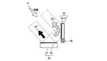
図1は、本発明による表示装置の一実施形態を説明するための図で、図中、10は表示装置、20は表示部、21はデュアルビュー液晶パネル、22は第1タッチパネル、30は反射部、31は反射部材、32は第2タッチパネル、40はヒンジ部である。
表示装置10は、表示部20と反射部30とを有し、表示部20は、デュアルビュー液晶パネル21及び第1タッチパネル22を含み、反射部30は、反射部材31及び第2タッチパネル32を含んでいる。FIG. 1 is a diagram for explaining an embodiment of a display device according to the present invention. In the figure, 10 is a display device, 20 is a display unit, 21 is a dual-view liquid crystal panel, 22 is a first touch panel, and 30 is reflective. , 31 is a reflecting member, 32 is a second touch panel, and 40 is a hinge part.
The
デュアルビュー液晶パネル21は、上述のように第1視野角内の位置で視認することができる第1画像と、第2視野角内の位置で視認できる第2画像とを同時に表示できるものである。
図1の例では、表示部20の前方D1に第1視野角が設定され、表示部20の後方D2に第2視野角が設定されている。つまり表示部20の第1視野角内に位置するユーザは、デュアルビュー液晶パネル21に表示される第1画像を視認することができる。As described above, the dual-view
In the example of FIG. 1, the first viewing angle is set at the front D <b> 1 of the
反射部30にはヒンジ部40が設けられ、ヒンジ部40を回動軸として、反射部30が回動自在となるように構成されている。ヒンジ部40によって、表示部20に対する反射部30の角度を可変設定することができる。また反射部材31には、ミラーなどによる反射面が設けられている。 The
ヒンジ部40は、表示部20と反射部30とを接続するように設けてもよく、また表示部20から離間した位置に配置してもよい。反射部30は、表示部20の第2画像を反射して、所望の方向D3に視野角(第3視野角とする)を与えることができればよい。第3視野角の方向は、反射部30の角度に応じて変化する。
また本発明では、ヒンジ機構を持ったヒンジ部40に限らず、反射部30の角度を可変設定できる構成であれば適宜採用することができる。あるいは、利用者の視線条件が限定された範囲であれば、ヒンジ部40を設けることなく、所定の角度で反射部30を固定した構成であってもよい。The
In the present invention, not only the
またデュアルビュー液晶パネル21の表示面側と、反射部材31の反射面側には、それぞれ第1及び第2タッチパネル22,32が設けられ、各タッチパネル22,32による入力操作を可能とする。 Further, first and
図2は、図1に示す表示装置による画像表示の機構を模式的に示す図である。
反射部材31は、デュアルビュー液晶パネル21に表示される第2画像を反射する。例えば図2のように、表示部20と反射部30とが互いにほぼ垂直になっている場合、方向D1に視野角を有する第1画像と、反射部材31で反射して方向D3に視野角を有する第2画像とが、視覚位置αから視認することができるようになる。このとき反射部材31で反射した第2画像は、デュアルビュー液晶パネル21で表示された画像が反転した画像(鏡像)となる。FIG. 2 is a diagram schematically showing a mechanism of image display by the display device shown in FIG.
The reflecting
従って、デュアルビュー液晶パネル21に表示させる第2画像には、利用者に視認させる画像を反転した鏡像を予め生成して表示させる。これにより、第2画像は、反射部材31で反転し、所望の画像となって利用者に視認できるようになる。 Therefore, as the second image to be displayed on the dual view
表示部20と反射部30を視認する利用者は、表示部20に備えられた第1タッチパネル22、及び反射部30に備えられた第2タッチパネル32を操作することによって、所望の入力を行うことができる。この場合、表示部20に表示された第1画像に従って、第1タッチパネル22を操作し、反射部30で反射した第2画像に従って、第2タッチパネル32を操作することができる。 A user who visually recognizes the
なおタッチパネル22,32は、表示部20及び反射部30における必須の要素ではなく、タッチパネル22,32を使用しない構成であってもよい。この場合、テンキー等のハードキー群や他のポインティングデバイス等によって入力操作が可能となるように構成する。 The
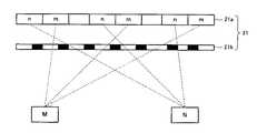
図3は、本発明に適用可能なデュアルビュー液晶パネルの表示原理を説明するための図である。
デュアルビュー液晶パネル21は、複数の画素m、nを有する液晶パネル21aと、液晶パネル21aの全面に配置されたパララックスバリア(光学系分離素子)21bとを備えている。パララックスバリア21bは、不透明領域によって隔たれた垂直な透光性スリットを複数有するスクリーンである。FIG. 3 is a diagram for explaining the display principle of a dual-view liquid crystal panel applicable to the present invention.
The dual view
液晶パネル21aの画素mを通過した光は、パララックスバリア21bが有する透光性スリットを介して、液晶パネル21aの表示面に対して所定の視野角に位置する視聴者Mに到達する。
また、液晶パネル21aの画素nを透過した光は、パララックスバリア21bが有する透光性スリットを介して、液晶パネル21aの表示面に対し所定の視野角に位置する視聴者Nに到達する。The light that has passed through the pixels m of the
Further, the light transmitted through the pixel n of the
液晶パネル21aに表示される画像は、パララックスバリア21bの複数の透光性スリットによって空間上の規定された領域からしか見えないようにしたものである。これにより、視聴者M及び視聴者Nは、各々、異なる画像を見ることが可能となる。 The image displayed on the
デュアルビュー表示を行なわせる場合には、たとえば、液晶パネル21aの隣り合う画素を視聴者M用の画像データ、または視聴者N用の画像データに応じて駆動させればよい。言い換えれば、液晶パネル21aの隣り合う画素は、互いに異なる方向用の画像データに応じて駆動されることになる。なお、画素は1個おきに互いに異なる画像データに応じて駆動されるようにしてもよいし、2個おき、あるいは3個おき等のように複数個おきに駆動させるようにしてもよく、いずれにしてもパララックスバリア21bの透光性スリットの幅に応じて設定すればよい。 When performing dual view display, for example, adjacent pixels of the
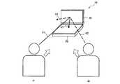
図4は、デュアルビュー液晶パネルと反射部材とによる視野を説明するための図である。
通常、利用者は、反射部30で反射した第2画像を視認することができるが、表示部20に表示した第2画像を反射部30により視認する場合、その視認可能な領域(反射部30による第3視野角)は、狭い範囲に限定される。FIG. 4 is a diagram for explaining the field of view by the dual-view liquid crystal panel and the reflecting member.
Normally, the user can visually recognize the second image reflected by the reflecting
すなわち図4に示すように、例えば表示装置10の正面に立つ利用者Pは、表示部20に表示した第1画像と、反射部30で反射した第2画像とを視認することができる。この場合、反射部30に対する利用者Pの視線V1の角度(入射角)が0に近いため、視線V1によって表示部20で表示された第2画像を視認することができる。 That is, as shown in FIG. 4, for example, the user P standing in front of the
これに対して、利用者Pの近傍に立つ他人Qが、その視線V2で反射部30を視認したときに、反射部30に対する視線V2の角度(入射角)が大きくなっているため、他人Qは表示部20に表示された第2画像を視認することができない。すなわち、反射部30を用いた構成により、反射部30によって得られる第2画像の視野角が非常に狭い範囲となる。勿論ここでは、表示部20による第1画像の視野角よりも反射部30による第2画像の視野角の方が小さい。 On the other hand, when the stranger Q standing in the vicinity of the user P visually recognizes the
このように、反射部30で反射した第2画像は、表示部20を正面から視認する利用者に対して、その利用者の側方からの覗き見は難しくなる。本発明の実施形態では、このようなデュアルビュー液晶パネル21を用いた表示部20と、反射部30とによる構成を利用して、反射部30で反射させる第2画像にセキュリティ情報を表示させる。これによりセキュリティ情報の他人への漏洩を効果的に防ぐことができるようになる。 As described above, the second image reflected by the reflecting
セキュリティ情報は、上述のようにセキュリティを確保すべき特定情報であり、例えば、ネットワーク設定などの特定権限の管理者等によって設定可能な、装置の基本設定に関する情報であり、あるいは個人情報、あるいはアドレス帳情報などに含まれる送信相手先を特定できる情報などが含まれる。
個人情報には、例えば個人の氏名、生年月日、年齢、性別、住所、電話番号、家族構成、趣味、嗜好、電子メールアドレス、勤務先、所属、勤務先住所、勤務先電話番号、クレジットカード番号、銀行口座番号、あるいは個人に付与された各種番号や文字列等を含むことができる。また他の情報と容易に照合することができ、 それにより特定の個人を識別することができる情報を含むことができる。The security information is specific information that should ensure security as described above. For example, the security information is information related to basic settings of the device that can be set by an administrator with specific authority such as network settings, or personal information or an address. This includes information that can identify the transmission destination included in the book information.
Personal information includes, for example, personal name, date of birth, age, gender, address, phone number, family structure, hobbies, preferences, e-mail address, work place, affiliation, work address, work phone number, credit card Numbers, bank account numbers, or various numbers and character strings assigned to individuals can be included. It can also contain information that can be easily matched against other information, thereby identifying specific individuals.
なおこの場合に、表示部20は、第1画像の表示領域の大きさよりも、第2画像の表示領域の大きさを小さくして表示を行うようにしてもよい。第2画像の表示領域を小さくすることにより、他人Qよる第2画像の視認がより困難になる。 In this case, the
図5は、本発明による表示装置を備えた電子機器の一実施形態を示す図で、本発明に関わる電子機器として、プリンタ、スキャナ、複写機、FAX等の機能を有する複合機を適用した例を示すものである。
複合機100は、CCD等により原稿の画像を読み取って画像信号を出力する画像読取装置(スキャナ)200と、画像読取装置200から送信される画像信号または外部から送信される画像信号に基づいて、用紙上に画像を印刷する電子写真方式のプリンタ300と、プリンタ300に順次用紙を供給する給紙デスク装置400とを備えている。FIG. 5 is a diagram showing an embodiment of an electronic apparatus provided with a display device according to the present invention, and an example in which a multifunction machine having functions of a printer, a scanner, a copying machine, a FAX, etc. is applied as an electronic apparatus related to the present invention. Is shown.
The
また画像読取装置200における原稿台201の側部には、操作パネル500が備えられている。操作パネル500には、上述したごとくの表示装置10が備えられる。この他、操作パネル500には、例えばスタートキー、テンキー、クリアキー、全解除キー、動作モードキー群などによるハードキー群70が設けられる。これらハードキー群70と、表示装置10に設けられているタッチパネルとを用いて、ユーザによる所定の入力操作が可能となっている。 An
表示装置10は、図1,図2に示すような構成で、表示部20と反射部30とを備えている。図5の例では、操作パネル500に対して表示部20が設けられ、原稿台201を構成する本体フレームに、反射部30が設けられる。反射部30は、ヒンジ部によって上記本体フレームに取り付けられ、その角度を可変設定することができる。 The
反射部30は、デュアルビュー液晶パネル21で表示される第2画像を反射して、第3視野角内に位置する利用者に対して、第2画像を視認させることができる。この場合、複合機100の利用者が第1画像と第2画像とを両方視認できるように、図2に示すように第1視野角と第3視野角が同一方向を向いていることが好ましい。 The
図6は、図5の複合機に対して反射部の取付位置を変更した例を示す図である。本例では、表示装置10の表示部20は、図5の例と同様に操作パネル500に設けられるが、反射部30は、原稿セットトレイ202が設けられている画像読取装置200の開閉可能なフレーム部に設けられている。 FIG. 6 is a diagram illustrating an example in which the attachment position of the reflection unit is changed with respect to the multifunction machine of FIG. In this example, the
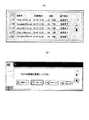
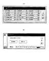
図7は、第1画像と第2画像の表示例を示す図で、図7(A)は表示部における第2画像の表示例を示す図、図7(B)は表示部における第1画像の表示例を示す図である。
また図8は、図7に示す表示画像を利用者が視認するときの表示例を示す図で、図8(A)は、反射部30を介して視認できる第2画像を示す図、図8(B)は、表示部20を直接見ることで視認できる第1画像を示す図である。FIG. 7 is a diagram illustrating a display example of the first image and the second image, FIG. 7A is a diagram illustrating a display example of the second image on the display unit, and FIG. 7B is a first image on the display unit. It is a figure which shows the example of a display.
8 is a diagram showing a display example when the user visually recognizes the display image shown in FIG. 7, and FIG. 8A is a diagram showing a second image that can be visually recognized through the
表示部20のデュアルビュー液晶パネルでは、図7(B)に示すような第1画像と、図7(A)に示すような第2画像とを同時に表示させることができる。
図7では、複合機のコピーモードにおけるジョブリストの表示例を示している。ジョブリストは、例えばコピーモードの入力待機画像に設定されているジョブステータス表示キーを押すことにより表示される画面である。The dual view liquid crystal panel of the
FIG. 7 shows a display example of a job list in the copy mode of the multifunction machine. The job list is a screen that is displayed, for example, by pressing a job status display key set for an input standby image in copy mode.
そしてこのときに第2画像において、上記のようなセキュリティ性の高い特定情報(セキュリティ情報)を表示させる。ここでは、図7(B)の第1画像には、ジョブの種類(印刷ジョブ、E−MAILジョブ、FAXジョブ、及びインターネットFAXジョブ)を選択する画面を表示し、第1画像で印刷ジョブを選択したときのジョブリストを第2画像に表示している。ジョブリストは、ユーザ名等のセキュリティ情報を含むため、第2画像に表示させる。 At this time, specific information (security information) having high security as described above is displayed in the second image. Here, a screen for selecting a job type (print job, E-MAIL job, FAX job, and Internet FAX job) is displayed on the first image in FIG. 7B, and the print job is displayed as the first image. The job list when selected is displayed in the second image. Since the job list includes security information such as a user name, the job list is displayed on the second image.
そして図7(A)の第2画像は、利用者に視認させたい画像を予め反転させて、鏡像の画像として表示させる。これにより図8に示すように、反射部30を介して視認される第2画像は、表示部20で表示された鏡像が反転した画像となっている。 The second image in FIG. 7A is displayed as a mirror image by inverting an image that the user wants to visually recognize in advance. As a result, as shown in FIG. 8, the second image visually recognized through the
上記のような構成により、セキュリティ情報を第2画像に表示させることで、セキュリティ情報の秘密性を維持することができるが、さらにこの構成によってジョブリストの表示領域を広くすることができる。
つまり従来通常の画面では、図7(B)のジョブ選択画面と、図7(A)のジョブリスト表示画面とは、同一の画面に表示されていたが、本実施例によって第2画像にジョブリストを表示させることにより、第2画像として表示させるジョブリストの表示面積を相対的に大きくすることができ、一度に視認できるジョブリストの情報量を増大させることができるようになる。With the above configuration, the security information can be displayed on the second image to maintain the confidentiality of the security information, but this configuration can further widen the job list display area.
That is, in the conventional normal screen, the job selection screen in FIG. 7B and the job list display screen in FIG. 7A are displayed on the same screen. By displaying the list, the display area of the job list displayed as the second image can be relatively increased, and the information amount of the job list that can be viewed at a time can be increased.
図9は、第1画像と第2画像の他の表示例を示す図で、図9(A)は、反射部30を介して視認できる第2画像を示す図、図9(B)は、表示部20を直接見ることで視認できる第1画像を示す図である。
ここでは、図7(B)のジョブ選択画面においてE−mailジョブを選択した状態を第1画像(図9(B))に表示し、このときのジョブリストを第2画像(図9(A))に表示する。この場合にも、ジョブリストには送信先情報によるセキュリティ情報を含むため、ジョブリストを第2画像に表示させる。FIG. 9 is a diagram illustrating another display example of the first image and the second image. FIG. 9A is a diagram illustrating the second image that can be visually recognized through the reflecting
Here, the state where the E-mail job is selected on the job selection screen of FIG. 7B is displayed on the first image (FIG. 9B), and the job list at this time is displayed on the second image (FIG. 9A). )). Also in this case, since the job list includes security information based on the transmission destination information, the job list is displayed on the second image.
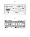
図10は、第1画像と第2画像の更に他の表示例を示す図で、図10(A)は、反射部30を介して視認できる第2画像を示す図、図10(B)は、表示部20を直接見ることで視認できる第1画像を示す図である。
図10の例は、複合機のスキャナモードにおいて取り込んだ画像を送信するときの設定画面を示している。ここでは送信先のアドレス帳画面を第2画像(図10(A))に表示し、アドレス帳のインデックス画面を第1画像(図10(B))に表示している。アドレス帳画面は、送信先の会社名や個人名、役職名等によるセキュリティ情報を含むため、第2画像に表示させる。10A and 10B are diagrams showing still another display example of the first image and the second image. FIG. 10A is a diagram showing the second image that can be visually recognized through the reflecting
The example of FIG. 10 shows a setting screen for transmitting an image captured in the scanner mode of the multifunction machine. Here, the destination address book screen is displayed in the second image (FIG. 10A), and the address book index screen is displayed in the first image (FIG. 10B). The address book screen is displayed on the second image because it includes security information based on the company name, personal name, title, etc. of the transmission destination.
図11は、第1画像と第2画像の更に他の表示例を示す図で、図11(A)は、反射部30を介して視認できる第2画像を示す図、図11(B)は、表示部20を直接見ることで視認できる第1画像を示す図である。
図11の例は、複合機が保持するアドレス帳データの設定画面を示している。ここではアドレス帳の設定用画面を第2画像(図11(A))に表示し、設定入力用のアルファベットキー画面を第1画像(図11(B))に表示している。アドレス帳の設定用画面は、相手先名やアドレス等のセキュリティ情報を含むため、第2画像に表示させる。11A and 11B are diagrams showing still another display example of the first image and the second image. FIG. 11A is a diagram showing the second image that can be visually recognized through the reflecting
The example of FIG. 11 shows a setting screen for address book data held by the multifunction machine. Here, the address book setting screen is displayed on the second image (FIG. 11A), and the alphabet key screen for setting input is displayed on the first image (FIG. 11B). Since the address book setting screen includes security information such as a destination name and an address, it is displayed on the second image.
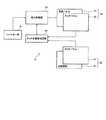
図12は、本発明による表示装置の内部構成を説明するためのブロック図である。表示装置10は、デュアルビュー液晶パネル21、デュアルビュー液晶パネル21に設けられた第1タッチパネル22、ミラー等の反射部材31、反射部材31に設けられた第2タッチパネル32、表示制御部50,タッチ位置検出回路60,及びテンキー等のハードキー群70を含む。 FIG. 12 is a block diagram for explaining the internal configuration of the display device according to the present invention. The
タッチ位置検出回路60は、第1タッチパネル22の表面電荷の変化を検出することによって、第1タッチパネル22上の利用者のタッチ位置を示す座標値を算出し、算出した座標値を表示制御部50に入力する。
またタッチ位置検出回路60は、第2タッチパネル32の表面電荷の変化を検出することによって、第2タッチパネル32上の利用者のタッチ位置を示す座標値を算出し、算出した座標値を表示制御部50に入力する。The touch
Further, the touch
表示制御部50は、デュアルビュー液晶パネル21の表示動作を制御するコンピュータであり、CPU、RAM、ROM等から構成される。特に表示制御部50は、タッチ位置検出回路60から入力される座標値に基づいて各タッチパネルに対するタッチ位置を検知し、検知したタッチ位置に応じて、デュアルビュー液晶パネル21に表示する第1画像の内容や第2画像の内容を切り換えや、表示領域の制御を行っている。またハードキー群70からの入力操作に応じて、表示条件設定や表示制御を行う。 The
以上本発明に関わる実施形態を説明したが、本発明では、上記のように単一の反射部材31を用いる構成に限定されるものではなく、複数の反射部材を用いて構成してもよい。例えば、表示部20に表示されている第2画像を反射する第1反射部と、第1反射部で反射した第2画像をさらに所望の視覚位置に向けて反射する第2反射部とを使用してもよい。この場合、第2画像は2回反射して視認されるため、上記の例のような鏡像ではなく、通常の画像を表示すればよい。 Although the embodiment related to the present invention has been described above, the present invention is not limited to the configuration using the
本発明に関わる表示装置は、上記の複合機のみならず各種の産業用電子機器や民生用電子機器に適用可能である。例えば、ATMや各種自動販売機等の電子機器にも適用することができる。
さらに、本発明に関わる表示装置は、タッチパネルを用いることなく、他の入力操作デバイスやキー等によって操作入力を行わせる電子機器に対しても適用することができる。例えば、表示画面を有する冷蔵庫や洗濯機等の機器であれば適用可能であり、本発明に関わる表示装置によって、セキュリティを確保すべき情報を他人から視認できないように表示させることができる。The display device according to the present invention can be applied to various industrial electronic devices and consumer electronic devices as well as the above-described multifunction peripherals. For example, the present invention can be applied to electronic devices such as ATMs and various vending machines.
Furthermore, the display device according to the present invention can also be applied to an electronic device that allows an operation input by another input operation device, a key, or the like without using a touch panel. For example, any device such as a refrigerator or a washing machine having a display screen can be applied, and the display device according to the present invention can display information that should ensure security from being viewed by others.
10…表示装置、20…表示部、21,210…デュアルビュー液晶パネル、21a…液晶パネル、21b…パララックスバリア、22…第1タッチパネル、30…反射部、31…反射部材、32…第2タッチパネル、40…ヒンジ部、50…表示制御部、60…タッチ位置検出回路、70…ハードキー群、100…複合機、200…画像読取装置、201…原稿台、202…原稿セットトレイ、220…バックライト、230…視覚位置、240…視覚位置、300…プリンタ、400…給紙デスク装置、500…操作パネル。DESCRIPTION OF
Claims (9)
Translated fromJapanese前記第2画像を反射するための反射部材と、
前記第1画像の表示情報に対する操作入力を可能とする操作手段とを有し、
予め定めた特定情報を前記第2画像によって表示し、該反射部材は、前記第2画像を視認することができる第3視野角を与える表示装置であって、
前記表示部は、前記操作手段による前記第1画像の表示情報に対する操作入力に応じた特定情報を、前記第2画像に表示させることを特徴とする表示装置。A display unit capable of simultaneously displaying a first image that can be viewed at a position within a first viewing angle and a second image that can be viewed at a position within a second viewing angle;
A reflecting member for reflecting theprevious SL second image,
Operation means for enabling operation input to display information of the first image,
Predetermined specific information is displayed by the second image, and the reflecting member is a display device that provides a third viewing angle that allows the second image to be viewed,
The display unit displaysspecific information correspondingto an operation input on display information of the first image by the operation means onthe second image .
Priority Applications (3)
| Application Number | Priority Date | Filing Date | Title |
|---|---|---|---|
| JP2006186791AJP4282694B2 (en) | 2006-07-06 | 2006-07-06 | Display device and electronic apparatus provided with the display device |
| CNA2007101282185ACN101101383A (en) | 2006-07-06 | 2007-07-05 | Display device and electronic equipment having the display device |
| US11/822,436US20080007482A1 (en) | 2006-07-06 | 2007-07-05 | Display apparatus and electronic apparatus having the display apparatus |
Applications Claiming Priority (1)
| Application Number | Priority Date | Filing Date | Title |
|---|---|---|---|
| JP2006186791AJP4282694B2 (en) | 2006-07-06 | 2006-07-06 | Display device and electronic apparatus provided with the display device |
Publications (2)
| Publication Number | Publication Date |
|---|---|
| JP2008015257A JP2008015257A (en) | 2008-01-24 |
| JP4282694B2true JP4282694B2 (en) | 2009-06-24 |
Family
ID=38918687
Family Applications (1)
| Application Number | Title | Priority Date | Filing Date |
|---|---|---|---|
| JP2006186791AActiveJP4282694B2 (en) | 2006-07-06 | 2006-07-06 | Display device and electronic apparatus provided with the display device |
Country Status (3)
| Country | Link |
|---|---|
| US (1) | US20080007482A1 (en) |
| JP (1) | JP4282694B2 (en) |
| CN (1) | CN101101383A (en) |
Families Citing this family (18)
| Publication number | Priority date | Publication date | Assignee | Title |
|---|---|---|---|---|
| US10915296B2 (en) | 2000-11-01 | 2021-02-09 | Flexiworld Technologies, Inc. | Information apparatus that includes a touch sensitive screen interface for managing or replying to e-mails |
| US10860290B2 (en) | 2000-11-01 | 2020-12-08 | Flexiworld Technologies, Inc. | Mobile information apparatuses that include a digital camera, a touch sensitive screen interface, support for voice activated commands, and a wireless communication chip or chipset supporting IEEE 802.11 |
| AU2002243279A1 (en) | 2000-11-01 | 2002-06-18 | Flexiworld Technologies, Inc. | Controller and manager for device-to-device pervasive digital output |
| US11204729B2 (en) | 2000-11-01 | 2021-12-21 | Flexiworld Technologies, Inc. | Internet based digital content services for pervasively providing protected digital content to smart devices based on having subscribed to the digital content service |
| AU2002239325A1 (en) | 2000-11-20 | 2002-05-27 | Flexiworld Technologies, Inc. | Systems and methods for mobile and pervasive output |
| US20020099884A1 (en) | 2001-01-19 | 2002-07-25 | Chang William Ho | Output controller systems and method for universal data output |
| JP4898733B2 (en)* | 2008-04-02 | 2012-03-21 | シャープ株式会社 | Display device and display method |
| JP4752868B2 (en)* | 2008-05-23 | 2011-08-17 | コニカミノルタビジネステクノロジーズ株式会社 | Image processing apparatus, image processing method, and image processing program |
| JP5455042B2 (en)* | 2009-01-14 | 2014-03-26 | 群創光電股▲ふん▼有限公司 | Multi-view display device |
| CN101551984B (en)* | 2009-03-23 | 2012-07-11 | 深圳超多维光电子有限公司 | Time division multiple visual display device and time division multiple visual display method |
| CN102768560B (en)* | 2012-03-26 | 2016-06-01 | 联想(北京)有限公司 | A kind of electronic equipment |
| CN103456281B (en)* | 2012-06-01 | 2016-01-27 | 联想(北京)有限公司 | A kind of state switching method and electronic equipment |
| DE102012215031A1 (en)* | 2012-08-23 | 2014-02-27 | Continental Automotive Gmbh | Display with a display, in particular for motor vehicles |
| CN103761551A (en)* | 2014-01-21 | 2014-04-30 | 中国工商银行股份有限公司 | Peep-prevention information collecting method and terminal |
| CN106156664A (en)* | 2016-07-26 | 2016-11-23 | 北京奇虎科技有限公司 | User interface anti-peeping method, system, application program and the terminal of application program |
| CN106445380A (en)* | 2016-09-19 | 2017-02-22 | 宇龙计算机通信科技(深圳)有限公司 | Multi-viewing-angle picture operating method and system and mobile terminal |
| JP7043254B2 (en)* | 2017-12-28 | 2022-03-29 | キヤノン株式会社 | Image processing device, control method and program of image processing device |
| JP7128720B2 (en) | 2018-10-25 | 2022-08-31 | 日立チャネルソリューションズ株式会社 | Input/output device and automatic transaction device |
Family Cites Families (20)
| Publication number | Priority date | Publication date | Assignee | Title |
|---|---|---|---|---|
| JPH05197507A (en)* | 1992-01-17 | 1993-08-06 | Hitachi Ltd | Portable computer |
| JPH06337656A (en)* | 1993-05-31 | 1994-12-06 | Hitachi Ltd | Liquid crystal display |
| EP1058181A4 (en)* | 1998-02-25 | 2002-09-11 | Sharp Kk | Display device |
| DE19808982A1 (en)* | 1998-03-03 | 1999-09-09 | Siemens Ag | Active matrix liquid crystal display |
| JP4834948B2 (en)* | 2000-02-07 | 2011-12-14 | ソニー株式会社 | Multiple screen simultaneous display device, multiple screen simultaneous display method, video signal generation device, and recording medium |
| JP2002374339A (en)* | 2001-06-15 | 2002-12-26 | Matsushita Electric Ind Co Ltd | Electronic apparatus |
| JP2003005912A (en)* | 2001-06-20 | 2003-01-10 | Hitachi Ltd | Display device with touch panel and display method |
| GB0123352D0 (en)* | 2001-09-28 | 2001-11-21 | Koninkl Philips Electronics Nv | Image display |
| JP4398141B2 (en)* | 2002-10-31 | 2010-01-13 | パイオニア株式会社 | Display apparatus and method |
| US7847786B2 (en)* | 2003-03-10 | 2010-12-07 | Koninklijke Philips Electronics, N.V. | Multi-view display |
| US20050114245A1 (en)* | 2003-04-07 | 2005-05-26 | First Data Corporation | Methods and systems for information management |
| GB2405489A (en)* | 2003-08-30 | 2005-03-02 | Sharp Kk | Display and reflector |
| JP4671591B2 (en)* | 2003-09-12 | 2011-04-20 | シャープ株式会社 | Information processing device |
| JP4098200B2 (en)* | 2003-09-16 | 2008-06-11 | シャープ株式会社 | Electronics |
| US7274418B2 (en)* | 2003-10-21 | 2007-09-25 | Symbol Technologies, Inc. | Method and system for improving the contrast of LCDs using circular polarization |
| US7336265B2 (en)* | 2004-06-17 | 2008-02-26 | Kyocera Mita Corporation | Display control device for touch panel-type setting-operation unit, electronic apparatus and image forming apparatus |
| JP2006047534A (en)* | 2004-08-03 | 2006-02-16 | Alpine Electronics Inc | Display control system |
| JP4628199B2 (en)* | 2005-07-01 | 2011-02-09 | アルパイン株式会社 | Display device |
| US7728824B2 (en)* | 2006-02-22 | 2010-06-01 | Sharp Kabushiki Kaisha | Display device, input device, printing device, and electric device |
| US20070262953A1 (en)* | 2006-05-15 | 2007-11-15 | Zackschewski Shawn R | Multiple-view display system having user manipulation control and method |
- 2006
- 2006-07-06JPJP2006186791Apatent/JP4282694B2/enactiveActive
- 2007
- 2007-07-05USUS11/822,436patent/US20080007482A1/ennot_activeAbandoned
- 2007-07-05CNCNA2007101282185Apatent/CN101101383A/enactivePending
Also Published As
| Publication number | Publication date |
|---|---|
| CN101101383A (en) | 2008-01-09 |
| US20080007482A1 (en) | 2008-01-10 |
| JP2008015257A (en) | 2008-01-24 |
Similar Documents
| Publication | Publication Date | Title |
|---|---|---|
| JP4282694B2 (en) | Display device and electronic apparatus provided with the display device | |
| US7728824B2 (en) | Display device, input device, printing device, and electric device | |
| JP4510845B2 (en) | Display system and image processing apparatus | |
| JP4382837B2 (en) | Display system and image processing apparatus | |
| US8045877B2 (en) | History information management device of image forming apparatus | |
| CN104079748A (en) | Job information display device | |
| JP5925749B2 (en) | Image forming apparatus | |
| US8643567B2 (en) | Multi-layer display | |
| JP2018169415A (en) | Image forming apparatus, image forming system, control program, and control method | |
| JP5093190B2 (en) | Image processing device | |
| US10063724B2 (en) | User interface for modifying a control's appearance to reflect a device's configuration | |
| CN101345802B (en) | Image forming device, information processing device, and display control method | |
| JP4425867B2 (en) | Display device, printing device | |
| JP7006454B2 (en) | Operation panel and image forming device | |
| JP4841332B2 (en) | Display device and electronic apparatus provided with the display device | |
| US10509550B2 (en) | Display device changing displayed image in accordance with depressed state on touch panel and image processing device using same | |
| JP2007226461A (en) | Input devices, electrical equipment | |
| JP2010243800A (en) | Image processing device | |
| JP2008175961A (en) | Input device | |
| JP2013120373A (en) | Display device and image forming apparatus including the same | |
| JP5331674B2 (en) | Image forming apparatus | |
| JP2004347657A (en) | Liquid crystal display device with touch panel | |
| JP5454436B2 (en) | Display processing apparatus and computer program | |
| JP2007253529A (en) | Electronic equipment, electronic equipment system, and paper template for setting the function of operation button | |
| JP2023142055A (en) | Touch input device and image forming apparatus comprising touch input device |
Legal Events
| Date | Code | Title | Description |
|---|---|---|---|
| A977 | Report on retrieval | Free format text:JAPANESE INTERMEDIATE CODE: A971007 Effective date:20080618 | |
| A131 | Notification of reasons for refusal | Free format text:JAPANESE INTERMEDIATE CODE: A131 Effective date:20080624 | |
| A521 | Request for written amendment filed | Free format text:JAPANESE INTERMEDIATE CODE: A523 Effective date:20080709 | |
| A131 | Notification of reasons for refusal | Free format text:JAPANESE INTERMEDIATE CODE: A131 Effective date:20081014 | |
| A521 | Request for written amendment filed | Free format text:JAPANESE INTERMEDIATE CODE: A523 Effective date:20081114 | |
| TRDD | Decision of grant or rejection written | ||
| A01 | Written decision to grant a patent or to grant a registration (utility model) | Free format text:JAPANESE INTERMEDIATE CODE: A01 Effective date:20090317 | |
| A01 | Written decision to grant a patent or to grant a registration (utility model) | Free format text:JAPANESE INTERMEDIATE CODE: A01 | |
| A61 | First payment of annual fees (during grant procedure) | Free format text:JAPANESE INTERMEDIATE CODE: A61 Effective date:20090317 | |
| R150 | Certificate of patent or registration of utility model | Ref document number:4282694 Country of ref document:JP Free format text:JAPANESE INTERMEDIATE CODE: R150 Free format text:JAPANESE INTERMEDIATE CODE: R150 | |
| FPAY | Renewal fee payment (event date is renewal date of database) | Free format text:PAYMENT UNTIL: 20120327 Year of fee payment:3 | |
| FPAY | Renewal fee payment (event date is renewal date of database) | Free format text:PAYMENT UNTIL: 20120327 Year of fee payment:3 | |
| FPAY | Renewal fee payment (event date is renewal date of database) | Free format text:PAYMENT UNTIL: 20130327 Year of fee payment:4 | |
| FPAY | Renewal fee payment (event date is renewal date of database) | Free format text:PAYMENT UNTIL: 20130327 Year of fee payment:4 | |
| FPAY | Renewal fee payment (event date is renewal date of database) | Free format text:PAYMENT UNTIL: 20140327 Year of fee payment:5 |