JP4278957B2 - Chemical injection unit - Google Patents
Chemical injection unitDownload PDFInfo
- Publication number
- JP4278957B2 JP4278957B2JP2002316435AJP2002316435AJP4278957B2JP 4278957 B2JP4278957 B2JP 4278957B2JP 2002316435 AJP2002316435 AJP 2002316435AJP 2002316435 AJP2002316435 AJP 2002316435AJP 4278957 B2JP4278957 B2JP 4278957B2
- Authority
- JP
- Japan
- Prior art keywords
- chemical
- weight
- measuring means
- elastic container
- chemical liquid
- Prior art date
- Legal status (The legal status is an assumption and is not a legal conclusion. Google has not performed a legal analysis and makes no representation as to the accuracy of the status listed.)
- Expired - Fee Related
Links
Images


Classifications
- A—HUMAN NECESSITIES
- A61—MEDICAL OR VETERINARY SCIENCE; HYGIENE
- A61M—DEVICES FOR INTRODUCING MEDIA INTO, OR ONTO, THE BODY; DEVICES FOR TRANSDUCING BODY MEDIA OR FOR TAKING MEDIA FROM THE BODY; DEVICES FOR PRODUCING OR ENDING SLEEP OR STUPOR
- A61M5/00—Devices for bringing media into the body in a subcutaneous, intra-vascular or intramuscular way; Accessories therefor, e.g. filling or cleaning devices, arm-rests
- A61M5/14—Infusion devices, e.g. infusing by gravity; Blood infusion; Accessories therefor
- A61M5/168—Means for controlling media flow to the body or for metering media to the body, e.g. drip meters, counters ; Monitoring media flow to the body
- A61M5/16831—Monitoring, detecting, signalling or eliminating infusion flow anomalies
- A61M5/1684—Monitoring, detecting, signalling or eliminating infusion flow anomalies by detecting the amount of infusate remaining, e.g. signalling end of infusion
- A61M5/16845—Monitoring, detecting, signalling or eliminating infusion flow anomalies by detecting the amount of infusate remaining, e.g. signalling end of infusion by weight
- A—HUMAN NECESSITIES
- A61—MEDICAL OR VETERINARY SCIENCE; HYGIENE
- A61M—DEVICES FOR INTRODUCING MEDIA INTO, OR ONTO, THE BODY; DEVICES FOR TRANSDUCING BODY MEDIA OR FOR TAKING MEDIA FROM THE BODY; DEVICES FOR PRODUCING OR ENDING SLEEP OR STUPOR
- A61M5/00—Devices for bringing media into the body in a subcutaneous, intra-vascular or intramuscular way; Accessories therefor, e.g. filling or cleaning devices, arm-rests
- A61M5/14—Infusion devices, e.g. infusing by gravity; Blood infusion; Accessories therefor
- A61M5/142—Pressure infusion, e.g. using pumps
- A61M5/145—Pressure infusion, e.g. using pumps using pressurised reservoirs, e.g. pressurised by means of pistons
- A61M5/148—Pressure infusion, e.g. using pumps using pressurised reservoirs, e.g. pressurised by means of pistons flexible, e.g. independent bags
- A61M5/152—Pressure infusion, e.g. using pumps using pressurised reservoirs, e.g. pressurised by means of pistons flexible, e.g. independent bags pressurised by contraction of elastic reservoirs
Landscapes
- Health & Medical Sciences (AREA)
- Hematology (AREA)
- Engineering & Computer Science (AREA)
- Anesthesiology (AREA)
- Biomedical Technology (AREA)
- Heart & Thoracic Surgery (AREA)
- Vascular Medicine (AREA)
- Life Sciences & Earth Sciences (AREA)
- Animal Behavior & Ethology (AREA)
- General Health & Medical Sciences (AREA)
- Public Health (AREA)
- Veterinary Medicine (AREA)
- External Artificial Organs (AREA)
- Infusion, Injection, And Reservoir Apparatuses (AREA)
Description
Translated fromJapanese【0001】
【発明の属する技術分野】
本発明は、医療分野で用いられる伸縮性容器を備えた薬液注入装置に採用される薬液計量装置に関するものである。
【0002】
【従来の技術】
従来、医療分野では、伸縮性容器と、この伸縮性容器の一端から吐出された薬液を患者に向けて送出する送出管路とを備えた薬液注入装置が種々開発されている。
【0003】
例えば、特許文献1には、図8に示すように、長手の概ねシリンダ状の伸縮性容器41と、この伸縮性容器41内に薬液を注入するための注入ポート42と、伸縮性容器の一端から吐出された薬液を患者に向けて送出する送出管路43とを備えた薬液注入装置40の技術が開示されている。
【0004】
この薬液注入装置40は、その伸縮性容器41の内部に伸縮性容器41の内径より大きい径を有する概ねシリンダ状の応力部材44を備えており、この応力部材44により、伸縮性容器41は径方向に多少のストレスがかかった状態で応力部材44に固定されている。
【0005】
この薬液注入装置40を使用する場合は、注射筒45等により注入ポート42を介して本装置40へ適切な薬液を注入すると、応力部材44に設けられた図略の逆流防止弁を介して伸縮性容器41へ薬液が進入し、伸縮性容器41内に貯留される。そして、伸縮性容器41の収縮力により加圧された薬液が、今度は応力部材44に設けられた孔46と送出管路43とを介して患者へと注入される。
【0006】
このような伸縮性容器41を備えた薬液注入装置40の場合、送出される薬液の量は、伸縮性容器41の形状の変化から判断せざるを得ず、薬液注入装置40の交換などのタイミングを判断するのが困難である。そのため、特許文献1に開示された技術では、伸縮性容器41内に充填された薬液の残量を確認するための手段として、応力部材44上に伸縮性容器41が空に近い状態を示すための複数個のインジケータバンプ47が設けられている。このインジケータバンプ47は、伸縮性容器41が膨張時には不可視であるが、伸縮性容器41が空に近づくにつれ応力部材44の両端側から順番に可視状態となるようにして伸縮性容器41内に充填された薬液の残量を判断することができるように構成されている。
【0007】
【特許文献1】
特公平4−36027
【0008】
【発明が解決しようとする課題】
しかしながら、上述の薬液注入装置40のインジケータバンプ47では、伸縮性容器41の形状の変化を示すだけであり、伸縮性容器41内に充填された薬液の残量を定量的に確認することはできないという不具合があった。
【0009】
一方、このような簡易な薬液注入装置に対しては、薬液の残量を定量的に確認するために複雑な計量機構を組み込むことは適当でない。また、患者に薬液を送出している現場では、速やかに伸縮性容器内に充填された薬液の残量を計量することが求められる。
【0010】
本発明は上記不具合に鑑みてなされたものであり、簡単かつ安価な装置により、患者に薬液を送出している現場で速やかに精度良く薬液の残量を計量することができる薬液注入装置の薬液計量装置を提供することを課題としている。
【0011】
【課題を解決するための手段】
上記課題を解決するための本発明は、伸縮性容器と、この伸縮性容器内に薬液を注入するための注入ポートと、伸縮性容器の収縮力により当該伸縮性容器の一端から吐出された薬液を患者に向けて送出する送出管路とを備えた薬液注入装置と、上記伸縮性容器内に充填された薬液の残量を計量するための薬液計量装置とを備え、上記薬液計量装置は、薬液注入装置の重量を測定する重量測定手段と、この重量測定手段に設けられ上記薬液注入装置を懸架する懸架手段とを備え、この懸架手段により、薬液注入装置を懸架することにより、薬液注入装置の重量を測定するように構成され、上記薬液注入装置は、上記懸架手段が着脱可能に懸架される吊具を備え、上記薬液計量装置は、紐状の連結具を備え、懸架手段が薬液注入装置を離脱している離脱状態において、この連結具により薬液注入装置と連結可能に構成されていることを特徴とする請求項1記載の薬液注入ユニットである。
【0012】
本発明によれば、重量測定手段を用いて薬液注入装置の重量を測定するので、確実に精度良く伸縮性容器内に充填された薬液の残量を計量することができる。
【0013】
また、本発明によれば、重量測定手段が、薬液注入装置を懸架する懸架手段を備え、この専用の懸架手段により、薬液注入装置を懸架して薬液注入装置の重量を測定するので、大掛かりな機構を必要とせず、必要最小限の簡単な構造で薬液注入装置の重量を測定することができる結果、製造に係るコストを抑制することができる。
【0014】
さらに、本発明によれば、懸架手段が、薬液注入装置に設けられた吊具を着脱自在に懸架するので、懸架手段が薬液注入装置を離脱している離脱状態において、測定手段が薬液注入装置の取り扱いの支障になることを防止できる。また、伸縮性容器内に充填された薬液の残量を計量する必要のある時は、速やかに懸架手段により薬液注入装置を測定手段に懸架状態にすることができる。
【0015】
また、本発明によれば、紐状の連結具により薬液計量装置と薬液注入装置とが連結されているので、懸架手段が薬液注入装置を離脱している離脱状態においても、常に測定手段を薬液注入装置の近傍に待機させて使用に供することができる結果、速やかな計量操作ができる。
【0016】
本発明の別の好ましい態様は、上記懸架手段は、袋状ケースに薬液注入装置を収納して懸架することにより薬液注入装置を懸架することを特徴とする請求項2記載の薬液注入装置の薬液計量装置である。
【0017】
この好ましい態様によれば、袋状ケースに薬液注入装置を収納して懸架手段が薬液注入装置を懸架するので、大掛かりな機構を必要とせず、簡単な構造で薬液注入装置の重量を測定することができる結果、製造に係るコストを抑制することができる。
【0018】
また、上記重量測定手段は、伸縮性容器内に薬液が充填されていない状態において、重量測定のインジケータが目盛り表示において零点を示すように零点補正されていることが好ましい。
【0019】
この好ましい態様によれば、伸縮性容器内に薬液が充填されていない状態で、重量測定のインジケータが目盛り表示において零点を示すように重量測定手段の零点が補正されているので、その都度薬液注入装置の重量を勘案せずとも重量測定手段の測定インジケータから一義的に伸縮性容器内に充填された薬液量を計量することができる。
【0020】
また、上記重量測定手段は、薬液注入装置の重量を支持する弾性部材を備え、この弾性部材の伸縮により、薬液注入装置の重量を測定する重量秤であることが好ましい。
【0021】
この好ましい態様によれば、重量測定手段は、薬液注入装置の重量を支持する弾性部材を備え、この弾性部材の伸縮により、薬液注入装置の重量を測定する重量秤であるので、簡単な機構で確実に精度良く計量することができるだけでなく、装置を小型にしてスペースを要しないものにすることができる。
【0022】
【発明の実施の形態】
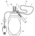
以下、添付図面を参照しながら本発明の好ましい実施の一形態について詳述する。図1は本発明の第一の実施の形態に係る薬液計量装置10の構成を示す側面図であり、図2は本発明の第一の実施の形態に係る薬液計量装置10の重量測定手段1の構成を示す説明図である。図2(a)は、側面図をまた、図2(b)は、(a)の断面図をそれぞれ示している。
【0023】
図1を参照して、図示の本発明の第一の実施の形態に係る薬液計量装置10は、伸縮性容器31と、この伸縮性容器31内に薬液を注入するための注入ポート32と、伸縮性容器31の一端から吐出された薬液を患者に向けて送出する送出管路33とを備えた薬液注入装置30に採用される薬液計量装置10であって、確実に精度良く伸縮性容器31内に充填された薬液の残量を定量的に計量することができるようにするために、重量測定手段1を有し、この重量測定手段1を用いて薬液注入装置30の重量を測定することにより、伸縮性容器31内に充填された薬液の残量を計量するように構成されている。
【0024】
そして、この重量測定手段1は、薬液注入装置30を懸架する懸架手段2を備え、この懸架手段2により、薬液注入装置30を懸架することにより、薬液注入装置30の重量を測定する。
【0025】
上記懸架手段2は、第一の実施の形態においては、金属製の円環状部材で構成され、この懸架手段2が薬液注入装置30に設けられた吊具3を着脱自在に懸架することができるように構成されている。これにより、懸架手段2は、一方で薬液注入装置30から離脱させて重量測定手段1が薬液注入装置30の取り扱いの支障になることを防止することができるとともに、他方で薬液の残量を計量する必要のある時は、速やかに薬液注入装置30を重量測定手段1に懸架状態にすることができるようになっている。
【0026】
そして、懸架手段2が薬液注入装置30を離脱している離脱状態においても、常に測定手段を薬液注入装置30の近傍に待機させて使用に供して速やかな計量操作ができるようにするために、この薬液計量装置10は、紐状の連結具4を備え、この連結具4により薬液注入装置30と連結可能に構成されている。
【0027】
次に、図2(a)、(b)を参照して、上記重量測定手段1は、簡単な機構で確実に精度良く計量することができるだけでなく、装置を小型にしてスペースを要しないものにすることができるようにするために、ケース5の中に、弾性部材6を備えた重量秤が採用されており、この弾性部材6は、棹部材7を介して懸架手段2に連結されることにより、薬液注入装置30の重量を支持し得るようになっている。
【0028】
上記弾性部材6は、本実施形態では、コイルスプリングが採用されており、このコイルスプリングが薬液注入装置30の重量により伸張することにより、その伸び量から重量が測定される。
【0029】
そして、伸縮性容器31内に充填された薬液の残量は、この重量秤からなる重量測定手段1の弾性部材6の伸張量をインジケータ8と目盛り表示9とにより確認することで計量されるが、その都度薬液注入装置30の重量を勘案せずとも重量測定手段1の目盛り表示9から一義的に伸縮性容器31内に充填された薬液量を計量することができるようにするために、伸縮性容器31内に薬液が充填されていない状態において、重量測定手段1のインジケータ8が目盛り表示9において零点を示すように零点補正されている。
【0030】
次に図3を参照して、本発明の第一の実施の形態に係る薬液計量装置10の作用について説明する。図3は、本発明の第一の実施の形態に係る薬液計量装置10の使用状態を示す説明図である。
【0031】
同図を参照して、本発明の第一の実施の形態に係る薬液計量装置10においては、図示のように、重量測定手段1の懸架手段2を用いて薬液注入装置30に設けられた吊具3を着脱自在に懸架することにより、薬液注入装置30全体の重量を重量測定手段1の弾性部材6(図2)に働かせ、この弾性部材6の伸張により、薬液注入装置30の重量を測定する。
【0032】
この時、重量測定手段1は、伸縮性容器31内に薬液が充填されていない状態において、重量測定のインジケータ8が目盛り表示9において零点を示すように事前に零点補正されているので、重量測定手段1の目盛り表示9から一義的に伸縮性容器31内に充填された薬液の残量が確認される。
【0033】
以上説明したように、本発明の第一の実施の形態に係る薬液計量装置10によれば、重量測定手段1を用いて薬液注入装置30の重量を測定するので、確実に精度良く伸縮性容器31内に充填された薬液の残量を計量することができる。
【0034】
また、重量測定手段1が、薬液注入装置30を懸架する懸架手段2を備え、この専用の懸架手段2により、薬液注入装置30を懸架して薬液注入装置30の重量を測定するので、大掛かりな機構を必要とせず、必要最小限の簡単な構造で薬液注入装置30の重量を測定することができる結果、製造に係るコストを抑制することができる。
【0035】
しかも、懸架手段2が、薬液注入装置30に設けられた吊具3を着脱自在に懸架するので、懸架手段2が薬液注入装置30を離脱している離脱状態において、重量測定手段1が薬液注入装置30の取り扱いの支障になることを防止できる。また、伸縮性容器31内に充填された薬液の残量を計量する必要のある時は、速やかに懸架手段2により薬液注入装置30を重量測定手段1に懸架状態にすることができる。
【0036】
また、紐状の連結具4により薬液計量装置10と薬液注入装置30とが連結されているので、懸架手段2が薬液注入装置30を離脱している離脱状態においても、常に測定手段を薬液注入装置30の近傍に待機させて使用に供することができる結果、速やかな計量操作ができる。
【0037】
さらに、伸縮性容器31内に薬液が充填されていない状態で、重量測定のインジケータ8が目盛り表示9において零点を示すように重量測定手段1の零点が補正されているので、その都度薬液注入装置30の重量を勘案せずとも重量測定手段1の目盛り表示から一義的に伸縮性容器31内に充填された薬液量を計量することができる。
【0038】
そして、重量測定手段1は、薬液注入装置30の重量を支持する弾性部材6を備え、この弾性部材6の伸縮により、薬液注入装置30の重量を測定する重量秤であるので、簡単な機構で確実に精度良く計量することができるだけでなく、装置を小型にしてスペースを要しないものにすることができる。
【0039】
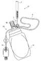
次に、図4を参照して、本発明の第二の実施の形態に係る薬液計量装置20について詳述する。図4は本発明の第二の実施の形態に係る薬液計量装置20の構成を示す側面図である。
【0040】
以下、第二の実施の形態の説明にあたっては、第一の実施の形態と重複する部分については同一の符号を付して説明を省略し、異なる部分について詳述するものとする。
【0041】
図4を参照して、本発明の第二の実施の形態に係る薬液計量装置20においては、上記懸架手段2は、簡単な構造で薬液注入装置30の重量を測定することができるようにするために、袋状ケース2aとリング2bと吊り紐2cとを備え、この袋状ケース2aに薬液注入装置30を収納するとともにリング2bで吊り紐2cを懸架することにより薬液注入装置30を懸架するように構成されている。
【0042】
このように、本発明の第二の実施の形態に係る薬液計量装置20によれば、袋状ケース2aに薬液注入装置30を収納して薬液注入装置30を懸架するので、大掛かりな機構を必要とせず、簡単な構造で薬液注入装置30の重量を測定することができる結果、製造に係るコストを抑制することができる。
【0043】
さらに、図5〜7を参照して、本発明の実施の形態に係る薬液計量装置10、20の重量測定手段1について変形例を説明する。
【0044】
図5は、重量測定手段1の変形例を示す断面図であり、(a)は、重量測定手段1の第一の変形例を示している。また、(b)は、重量測定手段1の第二の変形例を示している。また、(c)は、重量測定手段1の第三の変形例を示している。また、図6は、重量測定手段1の第四の変形例を示しており、(a)は、側面図を(b)は、断面図をそれぞれ示している。さらに図7は、重量測定手段1の第五の変形例を示している。
【0045】
図5(a)を参照して、重量測定手段1の第一の変形例においては、弾性部材6は、図示のように、ゴム片が採用されており、このゴム片が伸張することにより、その伸び量から被測定物の重量が測定される。
【0046】
図5(b)を参照して、重量測定手段1の第二の変形例においては、弾性部材6は、図示のように、樹脂性の蛇腹機構が採用されており、この樹脂性の蛇腹機構が伸張することにより、その伸び量から被測定物の重量が測定される。
【0047】
図5(c)を参照して、重量測定手段1の第三の変形例においては、弾性部材6は、コイルスプリングが採用されているが、図示のように、棹部材7の代わりに紐部材11が採用され、インジケータ8としてこの紐部材の結び目その他の識別部材が採用されている。また、懸架手段2は、この紐部材11を輪状にして構成されている。
【0048】
図6(a)(b)を参照して、重量測定手段1の第四の変形例においては、弾性部材6は、図示のように、棹部材7を囲繞するコイルスプリングが採用されており、このコイルスプリングが縮むことにより、その縮み量から被測定物の重量が測定される。
【0049】
図7を参照して、重量測定手段1の第五の変形例のように、目盛り表示9を逆に伸縮性容器31内に充填された薬液量が減少するにつれて増加するように設けることにより、患者に送液された薬液量を示すように構成することも可能である。
【0050】
上述した実施の形態は本発明の好ましい具体例を例示したものに過ぎず、本発明は上述した実施の形態に限定されない。
【0051】
例えば、弾性部材6は、本実施形態では、コイルスプリングが採用されており、このコイルスプリングが薬液注入装置30の重量により伸縮することにより、その伸び量から重量が測定されるが、必ずしも図示の形状に限定されない。重量による伸縮することにより被測定物の重量を測定することが可能なものであれば、種々の設計変更が可能である。
【0052】
懸架手段2は、第一の実施の形態においては、金属製の円環状部材で構成されているが、必ずしも図示の金属製の円環形状に限定されない。薬液注入装置30を着脱自在に懸架することができるものであれば、種々の設計変更が可能である。
【0053】
また、重量測定手段1も、弾性部材6、棹部材7、インジケータ8、目盛り表示9は、必ずしも図示の形状に限定されず、簡単な機構で確実に精度良く計量することができるものであれば、種々の設計変更が可能である。
【0054】
また、本発明の第二の実施の形態に係る薬液計量装置20においては、懸架手段2は、袋状ケース2aとリング2bと吊り紐2cを備え、この袋状ケース2aに薬液注入装置30を収納するとともにリング2bで吊り紐2cを懸架することにより薬液注入装置30を懸架するように構成されているが、リング2bと吊り紐2cは本発明を限定するものではなく、その他種々の設計変更が可能である。
【0055】
また、必ずしも図示のように伸縮性容器31内に薬液が充填されていない状態において、重量測定手段1のインジケータ8が目盛り表示において零点を示すように零点補正されることは必須ではなく、第五の変形例のように、逆に伸縮性容器31内に充填された薬液量が減少するにつれて増加するように設けて患者に送液された薬液量を示すなど種々の設計変更が可能である。
【0056】
その他、本発明の特許請求の範囲内で種々の設計変更が可能であることはいうまでもない。
【0057】
【発明の効果】
以上説明したように、本発明によれば、簡単かつ安価な装置により、患者に薬液を送出している現場で速やかに精度良く薬液の残量を定量的に計量することができるという顕著な効果を奏する。
【図面の簡単な説明】
【図1】 本発明の第一の実施の形態に係る薬液計量装置の構成を示す側面図である。
【図2】 本発明の第一の実施の形態に係る薬液計量装置の重量測定手段1の構成を示す説明図であり、(a)は、側面図である。また、(b)は、(a)の断面図である。
【図3】 本発明の第一の実施の形態に係る薬液計量装置の使用状態を示す説明図である。
【図4】 本発明の第二の実施の形態に係る薬液計量装置の構成を示す側面図である。
【図5】 重量測定手段の変形例を示す断面図であり、(a)は、重量測定手段1の第一の変形例を示している。また、(b)は、重量測定手段の第二の変形例を示している。また、(c)は、重量測定手段の第三の変形例を示している。
【図6】 重量測定手段の第四の変形例を示しており、(a)は、側面図である。また、(b)は、内部を示す断面図である。
【図7】 重量測定手段の第五の変形例を示している。
【図8】 従来の薬液計量装置の構成の一例を示す断面図である。
【符号の説明】
1 重量測定手段
2 懸架手段
3 吊具
4 連結具
5 ケース
6 弾性部材
8 インジケータ
9 目盛り表示
10 薬液計量装置
30 薬液注入装置
31 伸縮性容器
32 注入ポート
33 送出管路[0001]
BACKGROUND OF THE INVENTION
The present invention relates to a chemical liquid metering device employed in a chemical liquid injection device provided with a stretchable container used in the medical field.
[0002]
[Prior art]
2. Description of the Related Art Conventionally, in the medical field, various types of medical solution injectors have been developed that include an elastic container and a delivery pipe that sends a chemical discharged from one end of the elastic container toward a patient.
[0003]
For example, in Patent Document 1, as shown in FIG. 8, a substantially cylindrical elongated
[0004]
The
[0005]
When this chemical
[0006]
In the case of the
[0007]
[Patent Document 1]
JP 4-36027
[0008]
[Problems to be solved by the invention]
However, the
[0009]
On the other hand, it is not appropriate for such a simple chemical injection device to incorporate a complicated measuring mechanism in order to quantitatively check the remaining amount of the chemical. In addition, at the site where a chemical solution is being delivered to a patient, it is required to quickly measure the remaining amount of the chemical solution filled in the elastic container.
[0010]
The present invention has been made in view of the above problems, and a chemical solution for a chemical solution injection device capable of quickly and accurately measuring the remaining amount of the chemical solution at a site where the chemical solution is being delivered to a patient with a simple and inexpensive device. It is an object to provide a weighing device.
[0011]
[Means for Solving the Problems]
The present invention for solving the above problems includes an elastic container, an injection port for injecting a chemical into the elastic container, and a chemical discharged from one end of the elastic container by the contraction force of the elastic container A medical fluid injection device comprising a delivery line for delivering the fluid to the patient, and a chemical fluid metering device for measuring the remaining amount of the chemical fluid filled in the stretchable container, the chemical fluid metering device comprising: A weight measuring means for measuring the weight of the chemical liquid injector and a suspension means for suspending the chemical liquid injector provided in the weight measuring means, and the chemical liquid injector is suspended by the suspension means. The chemical injection device includes a suspension on which the suspension means is detachably suspended, the chemical measurement device includes a string-like connector, and the suspension means includes chemical injection. Disconnecting device In disengaged, a liquid injection unit according to claim 1, characterized inthat it is connectable configuration as the liquid injector by the connector.
[0012]
According to the present invention, since the weight of the chemical liquid injector is measured using the weight measuring means, the remaining amount of the chemical liquid filled in the stretchable container can be measured accurately and accurately.
[0013]
Further, according to the present invention, the weight measuring means includes the suspension means for suspending the chemical liquid injector, and the dedicated liquid means is used to suspend the chemical liquid injector and measure the weight of the chemical liquid injector. As a result of measuring the weight of the chemical solution injector with a minimum required simple structure without the need for a mechanism, manufacturing costs can be suppressed.
[0014]
Furthermore, according to the present invention, since the suspension means detachably suspends the suspension provided in the chemical liquid injector, the measuring means is the chemical injector when the suspension means is detached from the chemical injector. Can be prevented from hindering handling. In addition, when it is necessary to measure the remaining amount of the chemical liquid filled in the stretchable container, the chemical liquid injector can be quickly suspended from the measuring means by the suspension means.
[0015]
In addition, according tothe present invention , since the chemical measuring device and the chemical injection device are connected by the string-like connector, the measurement means is always connected to the chemical even in the detached state where the suspension means is detached from the chemical injection device. As a result of being able to wait for use in the vicinity of the injection device, it is possible to perform a quick weighing operation.
[0016]
According to another preferred aspect of the present invention, the suspension means suspends the chemical injection device by housing the chemical injection device in a bag-like case and suspending the chemical injection device. It is a weighing device.
[0017]
According to this preferred embodiment, since the chemical injection device is housed in the bag-like case and the suspension means suspends the chemical injection device, the weight of the chemical injection device can be measured with a simple structure without requiring a large-scale mechanism. As a result, manufacturing costs can be reduced.
[0018]
The weight measuring means is preferably zero-corrected so that the weight measurement indicator shows a zero point on the scale display when the elastic container is not filled with the chemical solution.
[0019]
According to this preferred aspect, the zero point of the weight measuring means is corrected so that the weight measurement indicator shows the zero point on the scale display in a state where the elastic container is not filled with the chemical solution. Without considering the weight of the apparatus, the amount of the chemical solution filled in the elastic container can be measured from the measurement indicator of the weight measuring means.
[0020]
Preferably, the weight measuring means is a weight scale that includes an elastic member that supports the weight of the chemical liquid injector and that measures the weight of the chemical liquid injector by expansion and contraction of the elastic member.
[0021]
According to this preferred embodiment, the weight measuring means includes a resilient member that supports the weight of the chemical liquid injector, and is a weight scale that measures the weight of the chemical liquid injector by expansion and contraction of the elastic member. Not only can accurate weighing be performed reliably, but also the device can be made small and space-saving.
[0022]
DETAILED DESCRIPTION OF THE INVENTION
Hereinafter, a preferred embodiment of the present invention will be described in detail with reference to the accompanying drawings. FIG. 1 is a side view showing a configuration of a chemical
[0023]
Referring to FIG. 1, a chemical
[0024]
The weight measuring unit 1 includes a
[0025]
In the first embodiment, the suspension means 2 is formed of a metal annular member, and the suspension means 2 can detachably suspend a
[0026]
And even in the detached state in which the suspension means 2 is detached from the chemical
[0027]
Next, referring to FIGS. 2 (a) and 2 (b), the weight measuring means 1 can not only accurately and accurately measure with a simple mechanism, but also has a small size and requires no space. In order to make it possible, a weight scale provided with an
[0028]
In the present embodiment, the
[0029]
The remaining amount of the chemical solution filled in the
[0030]
Next, with reference to FIG. 3, the operation of the chemical
[0031]
With reference to the figure, in the chemical | medical
[0032]
At this time, since the weight measuring means 1 is corrected in advance so that the
[0033]
As described above, according to the chemical
[0034]
In addition, the weight measuring unit 1 includes a
[0035]
Moreover, since the suspension means 2 removably suspends the hanging
[0036]
Moreover, since the chemical | medical
[0037]
Further, since the zero point of the weight measuring means 1 is corrected so that the
[0038]
The weight measuring unit 1 includes an
[0039]
Next, with reference to FIG. 4, the chemical | medical
[0040]
Hereinafter, in the description of the second embodiment, the same portions as those in the first embodiment are denoted by the same reference numerals, the description thereof is omitted, and different portions are described in detail.
[0041]
With reference to FIG. 4, in the chemical | medical
[0042]
Thus, according to the chemical | medical
[0043]
Furthermore, with reference to FIGS. 5-7, the modified example is demonstrated about the weight measurement means 1 of the chemical | medical
[0044]
FIG. 5 is a cross-sectional view showing a modified example of the weight measuring unit 1, and FIG. 5A shows a first modified example of the weight measuring unit 1. Further, (b) shows a second modification of the weight measuring means 1. Further, (c) shows a third modification of the weight measuring means 1. FIG. 6 shows a fourth modification of the weight measuring means 1, wherein (a) shows a side view and (b) shows a cross-sectional view. Further, FIG. 7 shows a fifth modification of the weight measuring means 1.
[0045]
Referring to FIG. 5 (a), in the first modified example of the weight measuring means 1, the
[0046]
Referring to FIG. 5B, in the second modification of the weight measuring means 1, the
[0047]
Referring to FIG. 5 (c), in the third modification of the weight measuring means 1, the
[0048]
6 (a) and 6 (b), in the fourth modification of the weight measuring means 1, the
[0049]
Referring to FIG. 7, as in the fifth modification of the weight measuring means 1, by providing the
[0050]
The above-described embodiment is merely a preferred specific example of the present invention, and the present invention is not limited to the above-described embodiment.
[0051]
For example, in the present embodiment, the
[0052]
In the first embodiment, the suspension means 2 is made of a metal annular member, but is not necessarily limited to the illustrated metal ring shape. As long as the
[0053]
Further, the weight measuring means 1 is not limited to the shape shown in the figure, and the
[0054]
Moreover, in the chemical | medical
[0055]
In addition, it is not essential that the zero point correction is performed so that the
[0056]
In addition, it goes without saying that various design changes are possible within the scope of the claims of the present invention.
[0057]
【The invention's effect】
As described above, according to the present invention, a remarkable effect that a remaining amount of a chemical solution can be quantitatively measured quickly and accurately at a site where the chemical solution is delivered to a patient with a simple and inexpensive device. Play.
[Brief description of the drawings]
FIG. 1 is a side view showing a configuration of a chemical liquid measuring device according to a first embodiment of the present invention.
FIG. 2 is an explanatory view showing the configuration of the weight measuring means 1 of the chemical liquid measuring device according to the first embodiment of the present invention, and (a) is a side view. (B) is a sectional view of (a).
FIG. 3 is an explanatory diagram showing a usage state of the chemical liquid measuring device according to the first embodiment of the present invention.
FIG. 4 is a side view showing a configuration of a chemical liquid measuring device according to a second embodiment of the present invention.
FIG. 5 is a cross-sectional view showing a modified example of the weight measuring unit, and (a) shows a first modified example of the weight measuring unit 1; (B) shows a second modification of the weight measuring means. Further, (c) shows a third modification of the weight measuring means.
FIG. 6 shows a fourth modification of the weight measuring means, and (a) is a side view. Further, (b) is a cross-sectional view showing the inside.
FIG. 7 shows a fifth modification of the weight measuring means.
FIG. 8 is a cross-sectional view showing an example of a configuration of a conventional chemical liquid measuring device.
[Explanation of symbols]
DESCRIPTION OF SYMBOLS 1 Weight measuring means 2 Suspension means 3
Claims (3)
Translated fromJapanese上記伸縮性容器内に充填された薬液の残量を計量するための薬液計量装置とを備え、
上記薬液計量装置は、薬液注入装置の重量を測定する重量測定手段と、この重量測定手段に設けられ上記薬液注入装置を懸架する懸架手段とを備え、この懸架手段により、薬液注入装置を懸架することにより、薬液注入装置の重量を測定するように構成され、
上記薬液注入装置は、上記懸架手段が着脱可能に懸架される吊具を備え、
上記薬液計量装置は、紐状の連結具を備え、懸架手段が薬液注入装置を離脱している離脱状態において、この連結具により薬液注入装置と連結可能に構成されていることを特徴とする薬液注入ユニット。An elastic container, an injection port for injecting a chemical into the elastic container, and a delivery line for sending the chemical discharged from one end of the elastic container to the patient by the contraction force of the elastic container; A chemical injection device comprising:
A chemical measuring device for measuring the remaining amount of the chemical filled in the elastic container,
The medicinal liquid measuring device includes weight measuring means for measuring the weight of the medicinal liquid injecting apparatus, and suspension means provided in the weight measuring means for suspending the medicinal liquid injecting apparatus, and the medicinal liquid injecting apparatus is suspended by the suspension means. Configured to measure the weight of the chemical injection device,
The chemical injection device includes a hanging tool on which the suspension means is removably suspended,
The chemical liquid metering device includes a string-like connector, and is configured to be connectable to the chemical liquid injector by the connector when the suspension means is detached from the chemical injector. Injection unit.
Priority Applications (5)
| Application Number | Priority Date | Filing Date | Title |
|---|---|---|---|
| JP2002316435AJP4278957B2 (en) | 2002-10-30 | 2002-10-30 | Chemical injection unit |
| US10/532,697US7611496B2 (en) | 2002-10-30 | 2003-10-27 | Liquid medicine-measuring device for liquid medicine-injecting device |
| PCT/JP2003/013680WO2004039437A1 (en) | 2002-10-30 | 2003-10-27 | Liquid medicine-measuring device for liquid medicine-injecting device |
| AU2003275673AAU2003275673A1 (en) | 2002-10-30 | 2003-10-27 | Liquid medicine-measuring device for liquid medicine-injecting device |
| EP03758915.7AEP1559441B1 (en) | 2002-10-30 | 2003-10-27 | Liquid medicine-measuring device for liquid medicine-injecting device |
Applications Claiming Priority (1)
| Application Number | Priority Date | Filing Date | Title |
|---|---|---|---|
| JP2002316435AJP4278957B2 (en) | 2002-10-30 | 2002-10-30 | Chemical injection unit |
Publications (2)
| Publication Number | Publication Date |
|---|---|
| JP2004147862A JP2004147862A (en) | 2004-05-27 |
| JP4278957B2true JP4278957B2 (en) | 2009-06-17 |
Family
ID=32211683
Family Applications (1)
| Application Number | Title | Priority Date | Filing Date |
|---|---|---|---|
| JP2002316435AExpired - Fee RelatedJP4278957B2 (en) | 2002-10-30 | 2002-10-30 | Chemical injection unit |
Country Status (5)
| Country | Link |
|---|---|
| US (1) | US7611496B2 (en) |
| EP (1) | EP1559441B1 (en) |
| JP (1) | JP4278957B2 (en) |
| AU (1) | AU2003275673A1 (en) |
| WO (1) | WO2004039437A1 (en) |
Families Citing this family (4)
| Publication number | Priority date | Publication date | Assignee | Title |
|---|---|---|---|---|
| JP5606729B2 (en) | 2009-12-16 | 2014-10-15 | 大研医器株式会社 | Injection tool and chemical injection system equipped with the same |
| WO2015136425A1 (en)* | 2014-03-10 | 2015-09-17 | CARLOS, Richer | Disposable diaper with diuresis indicator |
| US10444060B2 (en) | 2016-05-13 | 2019-10-15 | Adaptec Medical Devices LLC | Fluid container measurement system |
| EP3581108B1 (en) | 2016-05-13 | 2021-01-13 | Adaptec Medical Devices LLC | Fluid container measurement system employing load cell linkage member |
Family Cites Families (22)
| Publication number | Priority date | Publication date | Assignee | Title |
|---|---|---|---|---|
| US1587904A (en)* | 1924-08-29 | 1926-06-08 | Isaac O Duncan | Baby jumper |
| US2706755A (en)* | 1952-02-18 | 1955-04-19 | Louis R Krasno | Automatic fluid level indicator |
| US3107745A (en)* | 1961-11-16 | 1963-10-22 | Abbott Lab | Spring scale |
| US3389387A (en)* | 1965-09-10 | 1968-06-18 | Mark M. Hulse | Warning device |
| US3934474A (en)* | 1972-07-10 | 1976-01-27 | Methodist Hospital Of Indiana Inc. | Holding and monitoring apparatus for intravenous infusion container |
| US4454831A (en)* | 1983-07-14 | 1984-06-19 | Gallo Joseph S | Watering indicator for hanging plants |
| US4650464A (en)* | 1985-06-21 | 1987-03-17 | Minneapolis Medical Research Foundation, Inc. | Method for monitoring infusion of intravenous fluid into a patient |
| GB2190756B (en)* | 1986-03-21 | 1989-11-15 | Johnson Measures And Weights L | Spring balance |
| JPS6335262A (en) | 1986-07-29 | 1988-02-15 | 西村 重寿 | Apparatus for alarming reduction in quantity of dripping liquid |
| IT8822592A0 (en)* | 1988-11-11 | 1988-11-11 | Zorzi Ostilio | MEASUREMENT-SIGNALING APPARATUS FOR IV POLYSIS |
| JP2797654B2 (en) | 1990-05-30 | 1998-09-17 | いすゞ自動車株式会社 | Portable booster power supply |
| US5112319A (en)* | 1991-05-14 | 1992-05-12 | Eric Lai | Infusion alarm system |
| DE9414293U1 (en)* | 1994-09-05 | 1995-10-12 | Günther, Michael, 70569 Stuttgart | Remaining quantity alarm device for IV pole |
| US5545855A (en)* | 1994-11-22 | 1996-08-13 | Advanced Fishing Technologies, Inc. | Electronic fish scale for coding and storing weights and displaying same in inverse order |
| US5686704A (en)* | 1995-05-22 | 1997-11-11 | Simser; Daniel C. | Tare compensating tank weighing device |
| JP4014275B2 (en) | 1998-02-09 | 2007-11-28 | 黒田 庄二郎 | Infusion level monitoring device |
| US5922999A (en)* | 1998-06-15 | 1999-07-13 | Yang; Ah Mi | Portable scale for fishing purposes |
| US6429391B1 (en)* | 2000-06-16 | 2002-08-06 | Eric K. Gruver | Pocket-sized game scale and measuring device |
| US6371311B1 (en)* | 2000-07-10 | 2002-04-16 | L&P Property Management Company | Rack for storing product |
| US6564509B1 (en)* | 2000-12-29 | 2003-05-20 | Edward Zahner | Notification apparatus for watering houseplants |
| US6608261B2 (en)* | 2001-06-20 | 2003-08-19 | Mohan Thadani | Fishing scale with retractable handle and built-in mechanical thermometer |
| JP2004131102A (en)* | 2002-10-09 | 2004-04-30 | S T Chem Co Ltd | Hanging type medicine container |
- 2002
- 2002-10-30JPJP2002316435Apatent/JP4278957B2/ennot_activeExpired - Fee Related
- 2003
- 2003-10-27AUAU2003275673Apatent/AU2003275673A1/ennot_activeAbandoned
- 2003-10-27USUS10/532,697patent/US7611496B2/ennot_activeExpired - Fee Related
- 2003-10-27WOPCT/JP2003/013680patent/WO2004039437A1/enactiveApplication Filing
- 2003-10-27EPEP03758915.7Apatent/EP1559441B1/ennot_activeExpired - Lifetime
Also Published As
| Publication number | Publication date |
|---|---|
| US20060150725A1 (en) | 2006-07-13 |
| EP1559441B1 (en) | 2016-10-19 |
| EP1559441A1 (en) | 2005-08-03 |
| US7611496B2 (en) | 2009-11-03 |
| JP2004147862A (en) | 2004-05-27 |
| WO2004039437A1 (en) | 2004-05-13 |
| AU2003275673A1 (en) | 2004-05-25 |
| EP1559441A4 (en) | 2010-07-14 |
Similar Documents
| Publication | Publication Date | Title |
|---|---|---|
| AU2023200777B2 (en) | Method and apparatus for wetting internal fluid path surfaces of a fluid port to increase ultrasonic signal transmission | |
| CN102481406B (en) | Small non-electric medicine infusion device | |
| JP4278957B2 (en) | Chemical injection unit | |
| RU2014147366A (en) | INTRODUCTION OF MEDICINES WITH MEASUREMENT OF PRESSURE AND INTERRUPTED FLOW FOR IDENTIFICATION OF THE FILLED-IN FLUID ANATOMIC SPACE ENVIRONMENT AND FOR PROVIDING IN THEIR INJECTION | |
| EP3463218B1 (en) | Fastening device of a penis extension device with a tensile force meter | |
| US6663593B2 (en) | Disposable syringe with plunger rupture | |
| US5352213A (en) | Intravenous fluid flow monitor | |
| JP2023065444A (en) | Methods and systems for delivering therapeutic agents to implanted infusion devices | |
| US9950108B2 (en) | Bag balancer device and system | |
| IL120693A (en) | Flow indicators for ambulatory infusion | |
| CN106821648A (en) | A kind of medical scale | |
| CN208506047U (en) | A kind of blood analyser reagent liquid level sensing device | |
| US7753893B2 (en) | Drug solution injector with weighing scale | |
| KR20120118338A (en) | Device for sense of ringer solution level | |
| CN209019453U (en) | Infusion bottle cover and infusion bottle | |
| CN217404228U (en) | Titration apparatus for drug inspection | |
| US20050205158A1 (en) | Device for filling a flexible pouch | |
| CN221384674U (en) | Flow control device of infusion pump | |
| CN214970156U (en) | Intelligent medicine hanging device | |
| CN212940868U (en) | Infusion Pump Portable Device | |
| CN221692347U (en) | Double-scale syringe | |
| CN205411806U (en) | Blood transfusion system | |
| CN214667099U (en) | Multi-functional device of getting it filled of pharmacist | |
| CN211863454U (en) | Medical perfusion system | |
| CN205494524U (en) | Intravenous nutrition measures transfusion system |
Legal Events
| Date | Code | Title | Description |
|---|---|---|---|
| A621 | Written request for application examination | Free format text:JAPANESE INTERMEDIATE CODE: A621 Effective date:20050804 | |
| A131 | Notification of reasons for refusal | Free format text:JAPANESE INTERMEDIATE CODE: A131 Effective date:20080729 | |
| A521 | Request for written amendment filed | Free format text:JAPANESE INTERMEDIATE CODE: A523 Effective date:20080929 | |
| A02 | Decision of refusal | Free format text:JAPANESE INTERMEDIATE CODE: A02 Effective date:20081028 | |
| A521 | Request for written amendment filed | Free format text:JAPANESE INTERMEDIATE CODE: A523 Effective date:20090105 | |
| A911 | Transfer to examiner for re-examination before appeal (zenchi) | Free format text:JAPANESE INTERMEDIATE CODE: A911 Effective date:20090108 | |
| TRDD | Decision of grant or rejection written | ||
| A01 | Written decision to grant a patent or to grant a registration (utility model) | Free format text:JAPANESE INTERMEDIATE CODE: A01 Effective date:20090217 | |
| A01 | Written decision to grant a patent or to grant a registration (utility model) | Free format text:JAPANESE INTERMEDIATE CODE: A01 | |
| A61 | First payment of annual fees (during grant procedure) | Free format text:JAPANESE INTERMEDIATE CODE: A61 Effective date:20090311 | |
| FPAY | Renewal fee payment (event date is renewal date of database) | Free format text:PAYMENT UNTIL: 20120319 Year of fee payment:3 | |
| R150 | Certificate of patent or registration of utility model | Ref document number:4278957 Country of ref document:JP Free format text:JAPANESE INTERMEDIATE CODE: R150 Free format text:JAPANESE INTERMEDIATE CODE: R150 | |
| FPAY | Renewal fee payment (event date is renewal date of database) | Free format text:PAYMENT UNTIL: 20120319 Year of fee payment:3 | |
| FPAY | Renewal fee payment (event date is renewal date of database) | Free format text:PAYMENT UNTIL: 20130319 Year of fee payment:4 | |
| R250 | Receipt of annual fees | Free format text:JAPANESE INTERMEDIATE CODE: R250 | |
| FPAY | Renewal fee payment (event date is renewal date of database) | Free format text:PAYMENT UNTIL: 20130319 Year of fee payment:4 | |
| FPAY | Renewal fee payment (event date is renewal date of database) | Free format text:PAYMENT UNTIL: 20140319 Year of fee payment:5 | |
| R250 | Receipt of annual fees | Free format text:JAPANESE INTERMEDIATE CODE: R250 | |
| R250 | Receipt of annual fees | Free format text:JAPANESE INTERMEDIATE CODE: R250 | |
| R250 | Receipt of annual fees | Free format text:JAPANESE INTERMEDIATE CODE: R250 | |
| R250 | Receipt of annual fees | Free format text:JAPANESE INTERMEDIATE CODE: R250 | |
| R250 | Receipt of annual fees | Free format text:JAPANESE INTERMEDIATE CODE: R250 | |
| R250 | Receipt of annual fees | Free format text:JAPANESE INTERMEDIATE CODE: R250 | |
| R250 | Receipt of annual fees | Free format text:JAPANESE INTERMEDIATE CODE: R250 | |
| R250 | Receipt of annual fees | Free format text:JAPANESE INTERMEDIATE CODE: R250 | |
| R250 | Receipt of annual fees | Free format text:JAPANESE INTERMEDIATE CODE: R250 | |
| LAPS | Cancellation because of no payment of annual fees |