JP4277287B2 - Overhead traveling car - Google Patents
Overhead traveling carDownload PDFInfo
- Publication number
- JP4277287B2 JP4277287B2JP2006318044AJP2006318044AJP4277287B2JP 4277287 B2JP4277287 B2JP 4277287B2JP 2006318044 AJP2006318044 AJP 2006318044AJP 2006318044 AJP2006318044 AJP 2006318044AJP 4277287 B2JP4277287 B2JP 4277287B2
- Authority
- JP
- Japan
- Prior art keywords
- base
- rails
- overhead traveling
- rail
- guided
- Prior art date
- Legal status (The legal status is an assumption and is not a legal conclusion. Google has not performed a legal analysis and makes no representation as to the accuracy of the status listed.)
- Active
Links
- 239000000872bufferSubstances0.000description6
- 230000003028elevating effectEffects0.000description5
- 239000000428dustSubstances0.000description3
- 230000000694effectsEffects0.000description2
- 239000004065semiconductorSubstances0.000description1
- 230000009466transformationEffects0.000description1
- 235000012431wafersNutrition0.000description1
Images


Classifications
- B—PERFORMING OPERATIONS; TRANSPORTING
- B66—HOISTING; LIFTING; HAULING
- B66C—CRANES; LOAD-ENGAGING ELEMENTS OR DEVICES FOR CRANES, CAPSTANS, WINCHES, OR TACKLES
- B66C7/00—Runways, tracks or trackways for trolleys or cranes
- B66C7/08—Constructional features of runway rails or rail mountings
- B—PERFORMING OPERATIONS; TRANSPORTING
- B65—CONVEYING; PACKING; STORING; HANDLING THIN OR FILAMENTARY MATERIAL
- B65G—TRANSPORT OR STORAGE DEVICES, e.g. CONVEYORS FOR LOADING OR TIPPING, SHOP CONVEYOR SYSTEMS OR PNEUMATIC TUBE CONVEYORS
- B65G1/00—Storing articles, individually or in orderly arrangement, in warehouses or magazines
- B65G1/02—Storage devices
- B65G1/04—Storage devices mechanical
- B65G1/0407—Storage devices mechanical using stacker cranes
- B65G1/0435—Storage devices mechanical using stacker cranes with pulling or pushing means on either stacking crane or stacking area
- H—ELECTRICITY
- H01—ELECTRIC ELEMENTS
- H01L—SEMICONDUCTOR DEVICES NOT COVERED BY CLASS H10
- H01L21/00—Processes or apparatus adapted for the manufacture or treatment of semiconductor or solid state devices or of parts thereof
- H01L21/67—Apparatus specially adapted for handling semiconductor or electric solid state devices during manufacture or treatment thereof; Apparatus specially adapted for handling wafers during manufacture or treatment of semiconductor or electric solid state devices or components ; Apparatus not specifically provided for elsewhere
- H01L21/677—Apparatus specially adapted for handling semiconductor or electric solid state devices during manufacture or treatment thereof; Apparatus specially adapted for handling wafers during manufacture or treatment of semiconductor or electric solid state devices or components ; Apparatus not specifically provided for elsewhere for conveying, e.g. between different workstations
- H01L21/67763—Apparatus specially adapted for handling semiconductor or electric solid state devices during manufacture or treatment thereof; Apparatus specially adapted for handling wafers during manufacture or treatment of semiconductor or electric solid state devices or components ; Apparatus not specifically provided for elsewhere for conveying, e.g. between different workstations the wafers being stored in a carrier, involving loading and unloading
- H01L21/67766—Mechanical parts of transfer devices
- Y—GENERAL TAGGING OF NEW TECHNOLOGICAL DEVELOPMENTS; GENERAL TAGGING OF CROSS-SECTIONAL TECHNOLOGIES SPANNING OVER SEVERAL SECTIONS OF THE IPC; TECHNICAL SUBJECTS COVERED BY FORMER USPC CROSS-REFERENCE ART COLLECTIONS [XRACs] AND DIGESTS
- Y10—TECHNICAL SUBJECTS COVERED BY FORMER USPC
- Y10T—TECHNICAL SUBJECTS COVERED BY FORMER US CLASSIFICATION
- Y10T74/00—Machine element or mechanism
- Y10T74/18—Mechanical movements
- Y10T74/18568—Reciprocating or oscillating to or from alternating rotary
- Y10T74/18832—Reciprocating or oscillating to or from alternating rotary including flexible drive connector [e.g., belt, chain, strand, etc.]
- Y10T74/18848—Reciprocating or oscillating to or from alternating rotary including flexible drive connector [e.g., belt, chain, strand, etc.] with pulley
Landscapes
- Engineering & Computer Science (AREA)
- Mechanical Engineering (AREA)
- Condensed Matter Physics & Semiconductors (AREA)
- Physics & Mathematics (AREA)
- General Physics & Mathematics (AREA)
- Manufacturing & Machinery (AREA)
- Computer Hardware Design (AREA)
- Microelectronics & Electronic Packaging (AREA)
- Power Engineering (AREA)
- Robotics (AREA)
- Warehouses Or Storage Devices (AREA)
- Container, Conveyance, Adherence, Positioning, Of Wafer (AREA)
- Carriers, Traveling Bodies, And Overhead Traveling Cranes (AREA)
- Leg Units, Guards, And Driving Tracks Of Cranes (AREA)
Description
Translated fromJapaneseこの発明は天井走行車に関し、特に天井走行車に搭載した移載装置を、左右両側に進出させることができるようにすることに関する。 The present invention relates to an overhead traveling vehicle, and more particularly to enabling a transfer device mounted on an overhead traveling vehicle to advance to both the left and right sides.
特許文献1は、天井走行車に移載装置を走行方向の左右一方に進出させて、走行レールの側方向に設けたバッファ、即ちサイドバッファとの間で、物品を受け渡しすることを開示している。特許文献1では移載装置は左右片側にしか進出できないが、移載装置が左右両側に進出できると、
・ サイドバッファを増設する、特に処理装置の上部などにサイドバッファを増設できる、
・ 中央のサイドバッファを左右の天井走行車で共有する、
などの効果が得られる。このためには横移動の方向を左右両方向として、ストロークを長くする必要があるが、左右両方向とする機構が複雑になり、またストロークを長くすると剛性が必要なため、横移動機構(以下ラテラルドライブ)、の厚さが増す。この結果、天井走行車の高さサイズが増し、また天井走行車重量が増して、好ましくない。
・ Additional side buffers can be added, especially at the top of the processing unit.
・ Sharing the central side buffer between the left and right overhead traveling vehicles,
Effects such as can be obtained. For this purpose, it is necessary to lengthen the stroke by setting the direction of lateral movement to both the left and right directions, but the mechanism to make both the left and right directions becomes complicated, and the rigidity becomes necessary if the stroke is lengthened. ), Increase in thickness. As a result, the height size of the overhead traveling vehicle increases and the weight of the overhead traveling vehicle increases, which is not preferable.
この発明の課題は、小形軽量な機構で、天井走行車の走行方向左右両側に、物品を進出させることができるようにすることにある。
請求項2の発明での追加の課題は、ラテラルドライブからの発塵を抑制することにある。
この発明での追加の課題は、大きなストロークで移載装置を横移動させるための具体的な構成を提供することにある。An object of the present invention is to enable an article to advance on both the left and right sides in the traveling direction of an overhead traveling vehicle with a small and lightweight mechanism.
An additional problem in the invention of claim 2 is to suppress dust generation from the lateral drive.
This is an additional objectof the present invention is to provide a concrete configuration for traversing the transfer device with a large stroke.
この発明は、物品の移載装置を走行方向の左右に移動させるための横移動機構を設けた天井走行車において、
前記横移動機構は、上から下への順で、駆動手段を備えた固定のベース部と、
前記ベース部に支持され、左右に摺動自在でかつ、前記駆動手段により左右両側に進出し、さらに両端にストッパを備えた中間のミドル部と、
前記移載装置を支持し、前記ミドル部に支持され、左右に摺動自在でかつ、前記ミドル部の左右動に従動して左右動し、さらに両端にストッパを備えた先端のフロント部とを備え、
前記ベース部と前記ミドル部との間に、ベース部に設けたレールとミドル部に設けたレールとを平行に配設すると共に、これらの2本のレールでガイドされ、かつ該2本のレールに沿って移動自在でフリーな第1のリニアガイドを介して、前記ミドル部を前記ベース部によりガイドすると共に、ミドル部のストッパで押すことにより、第1のリニアガイドをベース部に対して移動させるようにし、
前記ミドル部と前記フロント部との間に、ミドル部に設けたレールとフロント部に設けたレールとを平行に配設すると共に、これらの2本のレールでガイドされ、かつ該2本のレールに沿って移動自在でフリーな第2のリニアガイドを介して、前記フロント部を前記ミドル部によりガイドすると共に、フロント部のストッパで押すことにより、第2のリニアガイドをミドル部に対して移動させるようにしたことを特徴とする。This invention is an overhead traveling vehicle provided with a lateral movement mechanism for moving the article transfer device to the left and right in the traveling direction.
The lateral movement mechanism includes, in order from top to bottom, a fixed base portion provided with driving means,
An intermediate middle part supported by the base part, slidable to the left and right, and advancedto the left and right sides by the driving means, and further provided with stoppers at both ends ;
Supporting the transfer device, supported by the middle portion, slidable to the left and right, and moved to the left and right by following the left and right movement of the middle portion, and a front portion at the tiphaving stoppers at both ends. Beiexample,
Between the base portion and the middle portion, a rail provided in the base portion and a rail provided in the middle portion are disposed in parallel, and are guided by these two rails, and the two rails The middle part is guided by the base part via the first linear guide which is freely movable along the center, and the first linear guide is moved with respect to the base part by pressing with the stopper of the middle part. And let
Between the middle part and the front part, a rail provided in the middle part and a rail provided in the front part are arranged in parallel, and are guided by these two rails, and the two rails The front part is guided by the middle part through a free second linear guide that can be moved along the center, and the second linear guide is moved relative to the middle part by pressing with the stopper of the front part. It was made to let it be made to do.
好ましくは、ベース部に設けた駆動手段としての駆動プーリにより、両端をミドル部に固定したベルトを駆動することにより、ミドル部を左右両側に進出自在にすると共に、一端をフロント部に他端をベース部に固定した一対のベルトを設けて、該一対のベルトの一方を、該ベルトのベース部側の端部よりも左右方向外側の位置でミドル部に設けたアイドラープーリにより折り返し、該一対のベルトの他方を、該ベルトのフロント部側の端部よりも左右方向外側の位置でミドル部に設けたアイドラープーリにより折り返すことにより、前記ミドル部の左右動に従動して前記フロント部を左右動させる。Preferably, by driving a belt having both ends fixed to the middle portion by a driving pulley provided as a driving means provided in the base portion, the middle portion can be advanced to both the left and right sides, and one end is connected to the front portion. A pair of belts fixed to the base part is provided, and one of the pair of belts is folded back by an idler pulley provided in the middle part at a position on the outer side in the left-right direction from the end part on the base part side of the belt. The other side of the belt is folded back by an idler pulley provided in the middle portion at a position on the outer side in the left-right direction with respect to the end portion on the front portion side of the belt.Let
この発明では、スカラアーム等のアームを用いる場合に比べ、小形軽量で高剛性な機構で移載装置を左右両側に進出させることができる。
この発明では、ベース部に設けたレールとミドル部に設けたレールとによりガイドされるリニアガイドでミドル部をガイドし、ミドル部に設けたレールとフロント部に設けたレールとでガイドされるリニアガイドでフロント部をミドル部によりガイドするので、大きなストロークで移載装置を確実に左右動させることができる。またリニアガイドはミドル部やフロン部のストッパで押されて移動する。In the present invention, the transfer device can be advanced to the left and right sides with a small, lightweight, and highly rigid mechanism as compared with the case of using an arm such as a SCARA arm.
In this invention, the middle part is guided by the linear guide guided by the rail provided in the base part and the rail provided in the middle part, and the linear guided by the rail provided in the middle part and the rail provided in the front part. Since the front portion is guided by the middle portion with the guide, the transfer device can be moved right and left with a large stroke. Further, the linear guide moves by being pushed by the stopper of the middle part or the front part.
ベース部に設けた駆動手段としての駆動プーリにより両端をミドル部に固定したベルトを駆動すると共に、一端をフロント部に他端をベース部に固定した一対のベルトを、ベルトの両固定端の外側の位置でミドル部に設けたアイドラープーリで従動させると、簡単に長いストロークでフロント部を左右両側に進出させることができ、かつチェーンを用いる場合に比べて発塵が少ない。A belt having both ends fixed to the middle portion is driven by a driving pulley provided as a driving means in the base portion, and a pair of belts having one end fixed to the front portion and the other end fixed to the base portion are arranged outside the both fixed ends of the belt. When driven by an idler pulley provided in the middle part at the position of, the front part can be easily advanced to the left and right sides with a long stroke, andless dust is generated than when a chain is used.
以下に本発明を実施するための最適実施例を示す。 In the following, an optimum embodiment for carrying out the present invention will be shown.
図1〜図7に、実施例の天井走行車2とその変形とを示す。各図において、4はレールで、クリーンルームなどの天井付近に設置され、6は搬送物品としてのカセットで、例えば半導体ウエハーなどを収容している。レール4は走行レール8と給電レール10とから成り、支柱12により天井から支持されている。 FIGS. 1-7 shows the overhead traveling vehicle 2 of an Example and its deformation | transformation. In each figure, 4 is a rail and is installed near the ceiling of a clean room or the like, and 6 is a cassette as a transported article, which accommodates, for example, semiconductor wafers. The rail 4 includes a traveling rail 8 and a
天井走行車2の走行部は走行レール8内に収容され、受電部は給電レール10内に収容されている。14はラテラルドライブで、θドライブ16,昇降ドライブ18及び昇降台20を走行レールの走行方向左右両側に進出させる。なおこの明細書では、走行レール4の走行方向に水平面内で直角な方向を左右方向という。また単に走行方向という場合、走行レール4に沿った方向である。θドライブ16は昇降ドライブ18及び昇降台20を水平面内で回動させ、設けなくても良い。昇降ドライブ18は昇降台20を昇降させ、昇降台20に設けた開閉自在なチャック21によりカセット6を吊り下げる。 The traveling part of the overhead traveling vehicle 2 is accommodated in the traveling rail 8, and the power receiving part is accommodated in the
天井走行車2では、ラテラルドライブ14によりカセット6を走行方向の左右両側に進出させることができるので、左右両側にバッファや棚,コンベヤ,ステーションなどを設けることができる。そして昇降台20の昇降により、処理装置のロードポートや走行レール4の下方のバッファとの間でカセット6の受け渡しができる。 In the overhead traveling vehicle 2, the
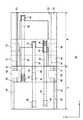
図2にラテラルドライブ14の駆動機構を示すと、上から下への順で、22はベース部で、天井走行車2の基部に固定の部材で、24は中間のミドル部、26は最下部のフロント部で、走行方向左右両側に進出する。なお以下ラテラルドライブ14での動作を説明する場合、左右方向が図2のx方向、走行方向が図2のy方向である。またSはフロント部26の左右動のストロークで、ベース部22のx方向の長さLよりも大きい。ベース部22には図示しない駆動モータを設け、28は駆動モータで駆動される駆動プーリ、30はアイドラープーリで、32は歯付ベルト、34,35は固定端である。そして駆動プーリ28並びにアイドラープーリ30はベース部22に、固定端34,35はミドル部24に設けられている。歯付ベルト32の一端は固定端34で固定され、プーリ28で折り返してプーリ30で再度折り返し、他端が固定端35で固定されている。駆動プーリ28の回動により、ミドル部24はベース部22の左右両側に進出する。 FIG. 2 shows the drive mechanism of the
36,37は一対の歯付ベルトで、38,39はアイドラープーリ、40〜43は固定端である。アイドラープーリ38,39はミドル部24に設けられ、固定端40,42はフロント部26に、固定端41,43はベース部22に設ける。これらによって駆動プーリ28での駆動量の2倍のストロークで、フロント部26をベース部22に対して左右動させることができる。また歯付ベルト32,36,37に変えて平ベルトやVベルトを用いても良い。 36 and 37 are a pair of toothed belts, 38 and 39 are idler pulleys, and 40 to 43 are fixed ends. The
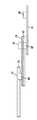
図3に、ラテラルドライブ14を図2の走行方向から見た姿を、模式的に示す。ラテラルドライブ14のフロント部26の下方には、θドライブ16や昇降ドライブ18,昇降台20が支持されている。ベース部22の例えば左右両側に一対のレール50,50があり、ミドル部24の上面側の例えば左右一対のレール51,51があり、レール50,51は互いに平行である。そして例えば左右一対のリニアガイド54,54が各2本のレール50,51によりガイドされる。ミドル部24の下面側には例えば左右一対のレール52,52があり、フロント部26の上面側にも例えば左右一対のレール53,53があり、レール52,53は互いに平行で、2本のレール52,53の双方でガイドされるリニアガイド55を例えば左右に設ける。 FIG. 3 schematically shows the
図4,5に示すようにレール50,51間にリニアガイド54を配置し、レール52,53間にリニアガイド55を配置すると、フロント部26を左右動させた場合、大きなストロークでフロント部26を左右動させることができる。ミドル部24のストロークはリニアガイド54のストロークの約2倍、ミドル部24に対するフロント部26のストロークはリニアガイド55のストロークの約2倍である。またレール50〜53の両端にストッパ57を設けて、リニアガイド54,55がレール50〜53から万一脱落することを防止することが好ましい。リニアガイド54,55はフリーであるが、ミドル部25やフロント部26が左右動する際に、ストッパ57で押されて左右動する。ミドル部25やフロント部26が左右動していない場合、θドライブ16や昇降ドライブ18等の自重による荷重でリニアガイド54,55が固定される。なお図3では、ストッパ57の図示を省略する。実施例では左右各一対のリニアガイド(54,54),(55,55)を設けたが、これらを左右一方のみ、あるいはラテラルドライブ14の中央部にのみ配置しても良い。リニアガイド54,55を左右一方にのみ設ける場合、左右方向の他方には例えば図7のレール70,71と複数個のローラ72とを設けて、ベース部22に対するミドル部24の運動や、ミドル部24に対するフロント部26の運動をガイドすることが好ましい。 When the
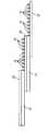
図6は、ミドル部24やフロント部26のガイドの参考例を示し、例えばミドル部24に運動方向に沿って一対のリニアガイド60,61を設けて、ベース部22のレール50でガイドする。また同様にフロント部26にも進退方向に沿って一対のリニアガイド62,63を設け、レール52でガイドする。この場合、ミドル部24やフロント部26の左右動により、一対のガイド60,61の一方がレール50から外れ、同様に一対のガイド62,63の一方がレール52から外れる。なおミドル部24やフロント部26をベース部22の下方へ復帰させると、全てのガイド60〜63がレール50,52で支持される。Figure 6 shows the guide ofreference example of the
図7にレール70,71とローラ72とを用いたガイドの参考例を示す。ローラ72はレール70内の図示しないガイド面に沿って回転し、ベース部22に対してミドル部24を、ミドル部24に対してフロント部26をガイドする。FIG. 7 shows areference example of a
実施例では以下の効果が得られる。
(1) スカラアーム等のアームを回動させる場合に比べ、軽量かつ小形で厚さの薄いラテラルドライブ14が得られる。このため天井走行車2の軽量化と、高さ方向のサイズのコンパクト化ができる。
(2) フロント部26のストロークSをベース部22のx方向の長さLよりも大きくできる。このため大きなストロークでカセット6を左右に移動させることができる。
(3) チェーンではなく歯付ベルトを用いるので、発塵が少なく、かつ高精度にカセット6を左右動できる。
(4) 図3,図4のリニアガイド54,55を用いることにより、容易に大きなストロークでフロント部26を左右動させることができる。またリニアガイド54,55は通常のリニアガイド分の厚さでよいので、ラテラルドライブ14の厚さが大きくならない。In the embodiment, the following effects can be obtained.
(1) The
(2) The stroke S of the
(3) Since a toothed belt is used instead of a chain, there is little dust generation and the cassette 6 can be moved left and right with high precision.
(4) By using the
2 天井走行車
4 レール
6 カセット
8 走行レール
10 給電レール
12 支柱
14 ラテラルドライブ
16 θドライブ
18 昇降ドライブ
20 昇降台
21 チャック
22 ベース部
24 ミドル部
26 フロント部
28 駆動プーリ
30,38,39 アイドラープーリ
32,36,37 歯付きベルト
34,35 固定端
40〜43 固定端
50〜53 レール
54,55 リニアガイド
57 ストッパ
60〜63 リニアガイド
70,71 レール
72 ローラ2 Overhead traveling vehicle 4 Rail 6 Cassette 8
Claims (2)
Translated fromJapanese前記横移動機構は、上から下への順で、駆動手段を備えた固定のベース部と、
前記ベース部に支持され、左右に摺動自在でかつ、前記駆動手段により左右両側に進出し、さらに両端にストッパを備えた中間のミドル部と、
前記移載装置を支持し、前記ミドル部に支持され、左右に摺動自在でかつ、前記ミドル部の左右動に従動して左右動し、さらに両端にストッパを備えた先端のフロント部とを備え、
前記ベース部と前記ミドル部との間に、ベース部に設けたレールとミドル部に設けたレールとを平行に配設すると共に、これらの2本のレールでガイドされ、かつ該2本のレールに沿って移動自在でフリーな第1のリニアガイドを介して、前記ミドル部を前記ベース部によりガイドすると共に、ミドル部のストッパで押すことにより、第1のリニアガイドをベース部に対して移動させるようにし、
前記ミドル部と前記フロント部との間に、ミドル部に設けたレールとフロント部に設けたレールとを平行に配設すると共に、これらの2本のレールでガイドされ、かつ該2本のレールに沿って移動自在でフリーな第2のリニアガイドを介して、前記フロント部を前記ミドル部によりガイドすると共に、フロント部のストッパで押すことにより、第2のリニアガイドをミドル部に対して移動させるようにしたことを特徴とする、天井走行車。In the overhead traveling vehicle provided with a lateral movement mechanism for moving the article transfer device to the left and right in the traveling direction,
The lateral movement mechanism includes, in order from top to bottom, a fixed base portion provided with driving means,
An intermediate middle part supported by the base part, slidable to the left and right, and advancedto the left and right sides by the driving means, and further provided with stoppers at both ends ;
Supporting said transfer device, is supported by the middle portion and slidable in the right and left, and right movement by being driven by the lateral movement of the middleportion, further the front portion of the distal endhaving a stopper at both ends Beiexample,
Between the base portion and the middle portion, a rail provided in the base portion and a rail provided in the middle portion are disposed in parallel, and are guided by these two rails, and the two rails The middle part is guided by the base part via the first linear guide which is freely movable along the center, and the first linear guide is moved with respect to the base part by pressing with the stopper of the middle part. And let
Between the middle part and the front part, a rail provided in the middle part and a rail provided in the front part are arranged in parallel, and are guided by these two rails, and the two rails The front part is guided by the middle part through a free second linear guide that can be moved along the center, and the second linear guide is moved relative to the middle part by pressing with the stopper of the front part. An overhead traveling vehicle characterized in that the vehicle is allowed to run.
一端をフロント部に他端をベース部に固定した一対のベルトを設けて、該一対のベルトの一方を、該ベルトのベース部側の端部よりも左右方向外側の位置でミドル部に設けたアイドラープーリにより折り返し、該一対のベルトの他方を、該ベルトのフロント部側の端部よりも左右方向外側の位置でミドル部に設けたアイドラープーリにより折り返すことにより、前記ミドル部の左右動に従動して前記フロント部を左右動させるようにしたことを特徴とする、請求項1の天井走行車。
By driving a belt having both ends fixed to the middle part by a driving pulley as a driving means provided in the base part, the middle part can be advanced to the left and right sides, and
A pair of belts having one end fixed to the front portion and the other end fixed to the base portion are provided, and one of the pair of belts is provided in the middle portion at a position on the outer side in the left-right direction with respect to the base portion side end portion of the belt. The belt is folded back by an idler pulley, and the other side of the pair of belts is folded by an idler pulley provided in the middle portion at a position on the outer side in the left-right direction with respect to the end portion on the front portion side of the belt. The overhead traveling vehicle according to claim 1, wherein the front portion is moved left and right.
Priority Applications (5)
| Application Number | Priority Date | Filing Date | Title |
|---|---|---|---|
| JP2006318044AJP4277287B2 (en) | 2006-11-27 | 2006-11-27 | Overhead traveling car |
| KR1020070091920AKR101127111B1 (en) | 2006-11-27 | 2007-09-11 | Overhead travelling vehicle |
| TW096134297ATW200900345A (en) | 2006-11-27 | 2007-09-13 | Overhead traveling vehicle |
| EP07021345AEP1925584B1 (en) | 2006-11-27 | 2007-10-31 | Overhead traveling vehicle having lateral movement mechanism |
| US11/945,603US7516859B2 (en) | 2006-11-27 | 2007-11-27 | Overhead traveling vehicle having lateral movement mechanism |
Applications Claiming Priority (1)
| Application Number | Priority Date | Filing Date | Title |
|---|---|---|---|
| JP2006318044AJP4277287B2 (en) | 2006-11-27 | 2006-11-27 | Overhead traveling car |
Publications (2)
| Publication Number | Publication Date |
|---|---|
| JP2008127200A JP2008127200A (en) | 2008-06-05 |
| JP4277287B2true JP4277287B2 (en) | 2009-06-10 |
Family
ID=39183194
Family Applications (1)
| Application Number | Title | Priority Date | Filing Date |
|---|---|---|---|
| JP2006318044AActiveJP4277287B2 (en) | 2006-11-27 | 2006-11-27 | Overhead traveling car |
Country Status (5)
| Country | Link |
|---|---|
| US (1) | US7516859B2 (en) |
| EP (1) | EP1925584B1 (en) |
| JP (1) | JP4277287B2 (en) |
| KR (1) | KR101127111B1 (en) |
| TW (1) | TW200900345A (en) |
Cited By (1)
| Publication number | Priority date | Publication date | Assignee | Title |
|---|---|---|---|---|
| WO2023233863A1 (en) | 2022-06-01 | 2023-12-07 | 村田機械株式会社 | Overhead transport vehicle |
Families Citing this family (17)
| Publication number | Priority date | Publication date | Assignee | Title |
|---|---|---|---|---|
| KR100743194B1 (en)* | 2006-03-22 | 2007-07-27 | 삼성전자주식회사 | Conveying system |
| JP4807424B2 (en)* | 2009-03-17 | 2011-11-02 | 村田機械株式会社 | Ceiling transfer system and article transfer method |
| JP5454985B2 (en)* | 2010-05-25 | 2014-03-26 | 村田機械株式会社 | Overhead traveling vehicles and methods for preventing jumping out of overhead traveling vehicles |
| JP2012086942A (en)* | 2010-10-19 | 2012-05-10 | Muratec Automation Co Ltd | Traverse mechanism of carrier vehicle |
| KR101874320B1 (en)* | 2011-11-29 | 2018-07-05 | 삼성전자주식회사 | Hoist apparatus and hoist transporting system |
| KR101829650B1 (en) | 2014-01-07 | 2018-02-19 | 무라다기카이가부시끼가이샤 | Transfer device and control method of transfer device |
| TW201628116A (en)* | 2015-01-22 | 2016-08-01 | 華亞科技股份有限公司 | Buffer storage plate for storing wafer carrier |
| CN105329784A (en)* | 2015-11-27 | 2016-02-17 | 广州文冲船厂有限责任公司 | Anti-deflection portal crane |
| US11052926B2 (en)* | 2016-09-26 | 2021-07-06 | Murata Machinery, Ltd. | Overhead transport system and overhead transport vehicle |
| CN108436497A (en)* | 2018-05-22 | 2018-08-24 | 南京工程学院 | A kind of flexible Z axis and C axis composite structures |
| JP7099245B2 (en)* | 2018-10-19 | 2022-07-12 | 株式会社ダイフク | Goods carrier |
| CN113998403B (en)* | 2020-07-28 | 2022-09-23 | 长鑫存储技术有限公司 | Transfer system and transfer method |
| US12131932B2 (en) | 2020-07-28 | 2024-10-29 | Changxin Memory Technologies, Inc. | Transfer system and transfer method |
| CN112209240B (en)* | 2020-10-23 | 2023-01-10 | 朔州正德科技发展有限公司 | Swing arm type suspension crane |
| IL302290A (en)* | 2020-10-26 | 2023-06-01 | Murata Machinery Ltd | Hanging Facility |
| JPWO2023218757A1 (en)* | 2022-05-10 | 2023-11-16 | ||
| CN115295469A (en)* | 2022-09-13 | 2022-11-04 | 华芯(嘉兴)智能装备有限公司 | Traversing device for OHT |
Family Cites Families (16)
| Publication number | Priority date | Publication date | Assignee | Title |
|---|---|---|---|---|
| FR1191667A (en)* | 1958-02-18 | 1959-10-21 | Lip | Method of remote control of a mobile element from a fixed support, device for its implementation, and its various applications |
| SE463219B (en)* | 1989-10-16 | 1990-10-22 | Sky Park Ab | LINES OF EXCHANGE SPECIFICALLY AT TRANSFER TRUCK IN PARKING HOUSE |
| US5385243A (en)* | 1992-05-20 | 1995-01-31 | Harnischfeger Engineers, Inc. | Modular system for automatically staging letters in connection with a letter sorting machine |
| US5460475A (en)* | 1993-10-21 | 1995-10-24 | H. K. Systems, Inc. | Long reach shuttle for storage and retrieval machine |
| JP3706186B2 (en)* | 1995-12-25 | 2005-10-12 | 日本トムソン株式会社 | Linear motion rolling guide unit device |
| US5839873A (en)* | 1996-03-28 | 1998-11-24 | Hk Systems, Inc. | Storage and retrieval machine with pre-tensioned shuttle guides |
| DE19623022A1 (en)* | 1996-06-08 | 1997-12-11 | Afb Anlagen Und Filterbau Gmbh | Telescopic table for taking loads |
| JPH11180505A (en) | 1997-12-22 | 1999-07-06 | Murata Mach Ltd | Rail truck system |
| JP4267742B2 (en)* | 1999-03-12 | 2009-05-27 | 平田機工株式会社 | Ceiling transfer device and distribution line system using the same |
| JP2001130713A (en)* | 1999-11-01 | 2001-05-15 | Ishikawajima Harima Heavy Ind Co Ltd | Starting fork |
| WO2004034438A2 (en)* | 2002-10-11 | 2004-04-22 | Brooks Automation, Inc. | Access to one or more levels of material storage shelves by an overhead hoist transport vehicle from a single track position |
| TWI246501B (en)* | 2003-02-03 | 2006-01-01 | Murata Machinery Ltd | Overhead traveling carriage system |
| JP4045451B2 (en) | 2003-12-26 | 2008-02-13 | 村田機械株式会社 | Overhead traveling vehicle system |
| JP4126559B2 (en)* | 2004-08-09 | 2008-07-30 | 村田機械株式会社 | Overhead traveling vehicle system |
| JP4674080B2 (en)* | 2004-12-14 | 2011-04-20 | 株式会社ダイフク | Sliding fork device |
| JP4221603B2 (en)* | 2005-03-31 | 2009-02-12 | 村田機械株式会社 | Overhead traveling vehicle system |
- 2006
- 2006-11-27JPJP2006318044Apatent/JP4277287B2/enactiveActive
- 2007
- 2007-09-11KRKR1020070091920Apatent/KR101127111B1/enactiveActive
- 2007-09-13TWTW096134297Apatent/TW200900345A/enunknown
- 2007-10-31EPEP07021345Apatent/EP1925584B1/enactiveActive
- 2007-11-27USUS11/945,603patent/US7516859B2/enactiveActive
Cited By (1)
| Publication number | Priority date | Publication date | Assignee | Title |
|---|---|---|---|---|
| WO2023233863A1 (en) | 2022-06-01 | 2023-12-07 | 村田機械株式会社 | Overhead transport vehicle |
Also Published As
| Publication number | Publication date |
|---|---|
| KR20080047963A (en) | 2008-05-30 |
| JP2008127200A (en) | 2008-06-05 |
| EP1925584A2 (en) | 2008-05-28 |
| KR101127111B1 (en) | 2012-03-26 |
| US7516859B2 (en) | 2009-04-14 |
| EP1925584B1 (en) | 2013-01-09 |
| EP1925584A3 (en) | 2010-05-05 |
| TW200900345A (en) | 2009-01-01 |
| US20080128376A1 (en) | 2008-06-05 |
| TWI366551B (en) | 2012-06-21 |
Similar Documents
| Publication | Publication Date | Title |
|---|---|---|
| JP4277287B2 (en) | Overhead traveling car | |
| JP6647528B2 (en) | lift device | |
| KR101495574B1 (en) | Transporting apparatus, transporting system, and elongation mechanism | |
| JP6168476B2 (en) | Transport cart and transport cart system | |
| JP5402233B2 (en) | Robot and article transfer system | |
| KR101419356B1 (en) | Carrier and overhead hoist system including the same | |
| JP2013245032A (en) | Article transport facility | |
| CN106183671A (en) | Wheel track dual-purpose all-around mobile carrying platform | |
| US7959396B2 (en) | Automated warehouse and method for controlling stacker crane in automated warehouse | |
| CN103738673A (en) | Belt conveyor with telescopic head | |
| JP3832745B2 (en) | Overhead traveling vehicle system | |
| KR100785606B1 (en) | Press panel automatic feeder | |
| CN110606317A (en) | A two-stage telescopic pallet and handling equipment | |
| JP6024720B2 (en) | Transfer equipment | |
| CN116553048A (en) | A high-speed hoist and an automated three-dimensional warehouse | |
| CN203652576U (en) | Belt conveyer with flexible head | |
| JP5859226B2 (en) | lift device | |
| WO2017026256A1 (en) | Industrial robot | |
| JP2005246460A (en) | Work transfer device between presses | |
| JP4395730B2 (en) | Route change moving device for transport cart | |
| JP6768454B2 (en) | Work transfer device | |
| KR20140103472A (en) | Slide unit of overhead hoist transport | |
| JP2012153160A (en) | Traverser | |
| JPH0460882B2 (en) | ||
| JP2001019115A (en) | Stacker crane |
Legal Events
| Date | Code | Title | Description |
|---|---|---|---|
| A131 | Notification of reasons for refusal | Free format text:JAPANESE INTERMEDIATE CODE: A131 Effective date:20080612 | |
| A521 | Request for written amendment filed | Free format text:JAPANESE INTERMEDIATE CODE: A523 Effective date:20080723 | |
| TRDD | Decision of grant or rejection written | ||
| A01 | Written decision to grant a patent or to grant a registration (utility model) | Free format text:JAPANESE INTERMEDIATE CODE: A01 Effective date:20090213 | |
| A01 | Written decision to grant a patent or to grant a registration (utility model) | Free format text:JAPANESE INTERMEDIATE CODE: A01 | |
| A61 | First payment of annual fees (during grant procedure) | Free format text:JAPANESE INTERMEDIATE CODE: A61 Effective date:20090226 | |
| FPAY | Renewal fee payment (event date is renewal date of database) | Free format text:PAYMENT UNTIL: 20120319 Year of fee payment:3 | |
| R150 | Certificate of patent or registration of utility model | Ref document number:4277287 Country of ref document:JP Free format text:JAPANESE INTERMEDIATE CODE: R150 Free format text:JAPANESE INTERMEDIATE CODE: R150 | |
| FPAY | Renewal fee payment (event date is renewal date of database) | Free format text:PAYMENT UNTIL: 20120319 Year of fee payment:3 | |
| FPAY | Renewal fee payment (event date is renewal date of database) | Free format text:PAYMENT UNTIL: 20130319 Year of fee payment:4 | |
| R250 | Receipt of annual fees | Free format text:JAPANESE INTERMEDIATE CODE: R250 | |
| FPAY | Renewal fee payment (event date is renewal date of database) | Free format text:PAYMENT UNTIL: 20130319 Year of fee payment:4 | |
| FPAY | Renewal fee payment (event date is renewal date of database) | Free format text:PAYMENT UNTIL: 20140319 Year of fee payment:5 | |
| R250 | Receipt of annual fees | Free format text:JAPANESE INTERMEDIATE CODE: R250 | |
| R250 | Receipt of annual fees | Free format text:JAPANESE INTERMEDIATE CODE: R250 | |
| R250 | Receipt of annual fees | Free format text:JAPANESE INTERMEDIATE CODE: R250 | |
| R250 | Receipt of annual fees | Free format text:JAPANESE INTERMEDIATE CODE: R250 | |
| R250 | Receipt of annual fees | Free format text:JAPANESE INTERMEDIATE CODE: R250 | |
| R250 | Receipt of annual fees | Free format text:JAPANESE INTERMEDIATE CODE: R250 | |
| R250 | Receipt of annual fees | Free format text:JAPANESE INTERMEDIATE CODE: R250 | |
| R250 | Receipt of annual fees | Free format text:JAPANESE INTERMEDIATE CODE: R250 | |
| R250 | Receipt of annual fees | Free format text:JAPANESE INTERMEDIATE CODE: R250 | |
| R250 | Receipt of annual fees | Free format text:JAPANESE INTERMEDIATE CODE: R250 | |
| R250 | Receipt of annual fees | Free format text:JAPANESE INTERMEDIATE CODE: R250 |