JP4276579B2 - Mounting structure of components installed in in-wheel motor - Google Patents
Mounting structure of components installed in in-wheel motorDownload PDFInfo
- Publication number
- JP4276579B2 JP4276579B2JP2004146074AJP2004146074AJP4276579B2JP 4276579 B2JP4276579 B2JP 4276579B2JP 2004146074 AJP2004146074 AJP 2004146074AJP 2004146074 AJP2004146074 AJP 2004146074AJP 4276579 B2JP4276579 B2JP 4276579B2
- Authority
- JP
- Japan
- Prior art keywords
- wheel
- motor
- vehicle
- component
- mounting structure
- Prior art date
- Legal status (The legal status is an assumption and is not a legal conclusion. Google has not performed a legal analysis and makes no representation as to the accuracy of the status listed.)
- Expired - Fee Related
Links
Images


Classifications
- B—PERFORMING OPERATIONS; TRANSPORTING
- B60—VEHICLES IN GENERAL
- B60K—ARRANGEMENT OR MOUNTING OF PROPULSION UNITS OR OF TRANSMISSIONS IN VEHICLES; ARRANGEMENT OR MOUNTING OF PLURAL DIVERSE PRIME-MOVERS IN VEHICLES; AUXILIARY DRIVES FOR VEHICLES; INSTRUMENTATION OR DASHBOARDS FOR VEHICLES; ARRANGEMENTS IN CONNECTION WITH COOLING, AIR INTAKE, GAS EXHAUST OR FUEL SUPPLY OF PROPULSION UNITS IN VEHICLES
- B60K7/00—Disposition of motor in, or adjacent to, traction wheel
- B60K7/0007—Disposition of motor in, or adjacent to, traction wheel the motor being electric
- B—PERFORMING OPERATIONS; TRANSPORTING
- B60—VEHICLES IN GENERAL
- B60G—VEHICLE SUSPENSION ARRANGEMENTS
- B60G13/00—Resilient suspensions characterised by arrangement, location or type of vibration dampers
- B60G13/16—Resilient suspensions characterised by arrangement, location or type of vibration dampers having dynamic absorbers as main damping means, i.e. spring-mass system vibrating out of phase
- B—PERFORMING OPERATIONS; TRANSPORTING
- B60—VEHICLES IN GENERAL
- B60G—VEHICLE SUSPENSION ARRANGEMENTS
- B60G3/00—Resilient suspensions for a single wheel
- B60G3/18—Resilient suspensions for a single wheel with two or more pivoted arms, e.g. parallelogram
- B60G3/20—Resilient suspensions for a single wheel with two or more pivoted arms, e.g. parallelogram all arms being rigid
- B—PERFORMING OPERATIONS; TRANSPORTING
- B60—VEHICLES IN GENERAL
- B60G—VEHICLE SUSPENSION ARRANGEMENTS
- B60G2202/00—Indexing codes relating to the type of spring, damper or actuator
- B60G2202/10—Type of spring
- B60G2202/12—Wound spring
- B—PERFORMING OPERATIONS; TRANSPORTING
- B60—VEHICLES IN GENERAL
- B60G—VEHICLE SUSPENSION ARRANGEMENTS
- B60G2204/00—Indexing codes related to suspensions per se or to auxiliary parts
- B60G2204/10—Mounting of suspension elements
- B60G2204/30—In-wheel mountings
- B—PERFORMING OPERATIONS; TRANSPORTING
- B60—VEHICLES IN GENERAL
- B60G—VEHICLE SUSPENSION ARRANGEMENTS
- B60G2300/00—Indexing codes relating to the type of vehicle
- B60G2300/50—Electric vehicles; Hybrid vehicles
- B—PERFORMING OPERATIONS; TRANSPORTING
- B60—VEHICLES IN GENERAL
- B60K—ARRANGEMENT OR MOUNTING OF PROPULSION UNITS OR OF TRANSMISSIONS IN VEHICLES; ARRANGEMENT OR MOUNTING OF PLURAL DIVERSE PRIME-MOVERS IN VEHICLES; AUXILIARY DRIVES FOR VEHICLES; INSTRUMENTATION OR DASHBOARDS FOR VEHICLES; ARRANGEMENTS IN CONNECTION WITH COOLING, AIR INTAKE, GAS EXHAUST OR FUEL SUPPLY OF PROPULSION UNITS IN VEHICLES
- B60K17/00—Arrangement or mounting of transmissions in vehicles
- B60K17/04—Arrangement or mounting of transmissions in vehicles characterised by arrangement, location or kind of gearing
- B60K17/043—Transmission unit disposed in on near the vehicle wheel, or between the differential gear unit and the wheel
- B60K17/046—Transmission unit disposed in on near the vehicle wheel, or between the differential gear unit and the wheel with planetary gearing having orbital motion
- B—PERFORMING OPERATIONS; TRANSPORTING
- B60—VEHICLES IN GENERAL
- B60K—ARRANGEMENT OR MOUNTING OF PROPULSION UNITS OR OF TRANSMISSIONS IN VEHICLES; ARRANGEMENT OR MOUNTING OF PLURAL DIVERSE PRIME-MOVERS IN VEHICLES; AUXILIARY DRIVES FOR VEHICLES; INSTRUMENTATION OR DASHBOARDS FOR VEHICLES; ARRANGEMENTS IN CONNECTION WITH COOLING, AIR INTAKE, GAS EXHAUST OR FUEL SUPPLY OF PROPULSION UNITS IN VEHICLES
- B60K7/00—Disposition of motor in, or adjacent to, traction wheel
- B60K2007/0038—Disposition of motor in, or adjacent to, traction wheel the motor moving together with the wheel axle
- B—PERFORMING OPERATIONS; TRANSPORTING
- B60—VEHICLES IN GENERAL
- B60K—ARRANGEMENT OR MOUNTING OF PROPULSION UNITS OR OF TRANSMISSIONS IN VEHICLES; ARRANGEMENT OR MOUNTING OF PLURAL DIVERSE PRIME-MOVERS IN VEHICLES; AUXILIARY DRIVES FOR VEHICLES; INSTRUMENTATION OR DASHBOARDS FOR VEHICLES; ARRANGEMENTS IN CONNECTION WITH COOLING, AIR INTAKE, GAS EXHAUST OR FUEL SUPPLY OF PROPULSION UNITS IN VEHICLES
- B60K7/00—Disposition of motor in, or adjacent to, traction wheel
- B60K2007/0092—Disposition of motor in, or adjacent to, traction wheel the motor axle being coaxial to the wheel axle
- Y—GENERAL TAGGING OF NEW TECHNOLOGICAL DEVELOPMENTS; GENERAL TAGGING OF CROSS-SECTIONAL TECHNOLOGIES SPANNING OVER SEVERAL SECTIONS OF THE IPC; TECHNICAL SUBJECTS COVERED BY FORMER USPC CROSS-REFERENCE ART COLLECTIONS [XRACs] AND DIGESTS
- Y10—TECHNICAL SUBJECTS COVERED BY FORMER USPC
- Y10S—TECHNICAL SUBJECTS COVERED BY FORMER USPC CROSS-REFERENCE ART COLLECTIONS [XRACs] AND DIGESTS
- Y10S903/00—Hybrid electric vehicles, HEVS
- Y10S903/902—Prime movers comprising electrical and internal combustion motors
- Y10S903/903—Prime movers comprising electrical and internal combustion motors having energy storing means, e.g. battery, capacitor
- Y10S903/904—Component specially adapted for hev
- Y10S903/906—Motor or generator
Landscapes
- Engineering & Computer Science (AREA)
- Mechanical Engineering (AREA)
- Chemical & Material Sciences (AREA)
- Combustion & Propulsion (AREA)
- Transportation (AREA)
- Arrangement Or Mounting Of Propulsion Units For Vehicles (AREA)
- Vehicle Body Suspensions (AREA)
Description
Translated fromJapanese本発明は、部品の搭載構造に関し、特に、インホイールモータの筐体の外周部に設けられる部品の搭載構造に関する。 The present invention relates to a component mounting structure, and more particularly to a component mounting structure provided on an outer peripheral portion of a casing of an in-wheel motor.
従来、車輪内に駆動力を発生するモータが設けられるインホイールモータを有する車両において、モータの筐体の外周部には、筐体内の圧力が一定になるように維持するブリーザ装置やモータの温度や回転数を検知するセンサに接続されるコネクタ等の部品が設けられる。たとえば、インホイールモータの筐体に設けられる部品として、磁気検出センサの故障を検出する装置が以下の公報に開示される。 Conventionally, in a vehicle having an in-wheel motor provided with a motor that generates a driving force in a wheel, a temperature of a breather device or a motor that maintains a constant pressure in the casing on the outer periphery of the casing of the motor And components such as connectors connected to sensors for detecting the number of rotations. For example, as a component provided in a housing of an in-wheel motor, a device that detects a failure of a magnetic detection sensor is disclosed in the following publication.
特開2000−224884号公報(特許文献1)は、小型・軽量化と共に故障検出が可能な検出装置を開示する。この検出装置は、モータの回転角度を磁気的に検出する。検出装置は、所定の電気角で配設され、2値的に磁界の強さを検出する3個以上の磁気検出センサと、該磁気検出センサの内、少なくとも1つの磁気検出センサの出力を反転させる反転装置と、全ての磁気検出センサの出力が等しい場合、センサ異常を出力する出力装置とを含む。 Japanese Patent Laying-Open No. 2000-224884 (Patent Document 1) discloses a detection device capable of detecting a failure with a reduction in size and weight. This detection device magnetically detects the rotation angle of the motor. The detection device is arranged at a predetermined electrical angle, and three or more magnetic detection sensors that binaryly detect the strength of the magnetic field, and the output of at least one of the magnetic detection sensors is inverted. And an output device that outputs sensor abnormality when the outputs of all the magnetic detection sensors are equal.
特許文献1に開示された検出装置によると、磁気検出センサの内の1つの出力を反転させることで、全ての磁気検出センサの出力が等しくなることを防ぐことができる。このため、検磁気検出センサの出力が等しくなることを検出することで、検出装置の故障、検出装置のケーブルの切断、コネクタ外れ等を判断できる。
しかしながら、インホイールモータにおいて、モータの高出力が要求されたり、また車両の乗り心地を改善するため、モータを弾性部材により支持するいわゆるダイナミックマスダンパ機構が設けられたりすると、インホイールモータの構造は大きくなる。そのため、モータの軸長が、車輪の幅よりも大きくなり、車輪から車両の内側にモータの筐体が突出する可能性がある。モータの筐体の車輪から突出した部位に、上述したブリーザ装置、センサに設けられるコネクタあるいは特許文献1に開示された検出装置が設けられると、車輪が巻き上げる飛び石がホイールハウスの内面で跳ね返って、上述した部品に衝突して、部品が破損する恐れがあった。 However, in an in-wheel motor, if a high output of the motor is required, or a so-called dynamic mass damper mechanism that supports the motor with an elastic member is provided in order to improve the riding comfort of the vehicle, the structure of the in-wheel motor is growing. Therefore, the shaft length of the motor becomes larger than the width of the wheel, and the motor casing may protrude from the wheel to the inside of the vehicle. When the above-described breather device, the connector provided in the sensor, or the detection device disclosed in Patent Document 1 is provided in a portion protruding from the wheel of the motor housing, the stepping stones rolled up by the wheel rebound on the inner surface of the wheel house, There was a risk of the parts being damaged by colliding with the parts described above.
本発明は、上述のような課題を解決するためになされたものであって、その目的は、車輪が巻き上げる飛び石の衝突による破損を防止する部品の搭載構造を提供することがである。 The present invention has been made in order to solve the above-described problems, and an object of the present invention is to provide a component mounting structure that prevents damage due to a collision of a stepping stone that a wheel rolls up.
第1の発明に係る部品の搭載構造は、車輪の駆動力を発生するモータを車輪内に有するインホイールモータの筐体の外周部に設けられる部品の搭載構造である。モータは、車輪の幅よりも長い軸長を有する。部品は、モータの回転軸よりも上方の位置であってかつモータと車輪との間の位置に設けられる。位置は、車両の幅方向における車輪の内部である。 The component mounting structure according to the first aspect of the present invention is a component mounting structure provided on an outer peripheral portion of a casing of an in-wheel motor having a motor that generates a driving force for the wheel in the wheel. The motor has an axial length longer than the width of the wheel. The component is provided at a position above the rotating shaft of the motor and between the motor and the wheel. The position is inside the wheel in the width direction of the vehicle.
第1の発明によると、モータが車輪の幅よりも長い軸長を有する場合、部品(たとえば、ブリーザ装置)は、モータの回転軸よりも上方の位置であってかつモータと車輪との間の位置に設けられる。位置は、車両の幅方向における車輪の内部である。モータが駆動して車両が走行状態になると、車輪は回転に伴なって路面に散在する石、砂、ゴミなどの異物等(以下、石、砂、ゴミなどの異物等を含めて飛び石と記載する。)を巻き上げる。このとき、車輪は、車輪の後方側に飛び石を巻き上げる。車輪により巻き上げられた飛び石は、ホイールハウスの内面で跳ね返る。ホイールハウスの内面で跳ね返った飛び石のうち、部品に向かって飛散する飛び石は、部品が車輪とモータとの間に設けられるため、車輪に衝突する。すなわち、車輪自体が部品を飛び石の衝突から保護する。したがって、車輪が巻き上げる飛び石の衝突による破損を防止する部品の搭載構造を提供することができる。 According to the first invention, when the motor has an axial length longer than the width of the wheel, the component (for example, the breather device) is located above the rotational axis of the motor and between the motor and the wheel. Provided in position. The position is inside the wheel in the width direction of the vehicle. When the motor is driven and the vehicle is in a running state, the wheels are described as a stepping stone including foreign objects such as stones, sand, and dust scattered on the road surface as they rotate (hereinafter, including foreign objects such as stones, sand, and garbage). ). At this time, the wheel rolls up a stepping stone on the rear side of the wheel. Stepping stones rolled up by wheels bounce off the inside of the wheelhouse. Of the stepping stones that bounce off the inner surface of the wheel house, the stepping stones scattered toward the component collide with the wheel because the component is provided between the wheel and the motor. That is, the wheels themselves protect the parts from stepping stone collisions. Therefore, it is possible to provide a component mounting structure that prevents damage caused by the collision of the stepping stones rolled up by the wheels.
第2の発明に係る部品の搭載構造は、車輪の駆動力を発生するモータを車輪内に有するインホイールモータの筐体の外周部に設けられる部品の搭載構造である。モータは、車輪の幅よりも長い軸長を有する。部品は、モータの回転軸よりも上方の位置であってかつ車両の前方側の位置に設けられる。位置は、車両の幅方向における車輪の外部である。 The component mounting structure according to the second aspect of the present invention is a component mounting structure provided on the outer peripheral portion of the casing of an in-wheel motor having a motor for generating wheel driving force in the wheel. The motor has an axial length longer than the width of the wheel. The component is provided at a position above the rotating shaft of the motor and at the front side of the vehicle. The position is outside the wheel in the width direction of the vehicle.
第2の発明によると、モータが車輪の幅よりも長い軸長を有する場合、部品(たとえば、ブリーザ装置)は、モータの回転軸よりも上方の位置であってかつ車両の前方側の位置に設けられる。位置は、車両の幅方向における車輪の外部である。モータが駆動して車両が走行状態になると、車輪は回転に伴なって飛び石を巻き上げる。このとき、車輪は、車輪の後方側に飛び石を巻き上げる。車輪により巻き上げられた飛び石は、ホイールハウスの内面で跳ね返る。ホイールハウスの内面で跳ね返った飛び石は、モータの筐体において、モータの回転軸よりも車両の後方側の部位に衝突する。すなわち、部品をモータの回転軸よりも車両の前方側に設けることにより、車輪から車両の内側に突出した筐体の部位であっても、飛び石の衝突を回避することができる。したがって、車輪が巻き上げる飛び石の衝突による破損を防止する部品の搭載構造を提供することができる。 According to the second invention, when the motor has an axial length longer than the width of the wheel, the component (for example, the breather device) is located above the rotational axis of the motor and at the front side of the vehicle. Provided. The position is outside the wheel in the width direction of the vehicle. When the motor is driven and the vehicle is in a running state, the wheels roll up the stepping stones as they rotate. At this time, the wheel rolls up a stepping stone on the rear side of the wheel. Stepping stones rolled up by wheels bounce off the inside of the wheelhouse. The stepping stones that bounce off the inner surface of the wheel house collide with the rear side of the vehicle with respect to the rotating shaft of the motor in the motor housing. In other words, by providing the components on the front side of the vehicle with respect to the rotating shaft of the motor, it is possible to avoid a stepping stone collision even at a portion of the casing that protrudes from the wheels to the inside of the vehicle. Therefore, it is possible to provide a component mounting structure that prevents damage caused by the collision of the stepping stones rolled up by the wheels.
第3の発明に係る部品の搭載構造は、車輪の駆動力を発生するモータを車輪内に有するインホイールモータの筐体の外周部に設けられる部品の搭載構造である。モータは、車輪の幅よりも長い軸長を有する。部品は、モータの回転軸よりも上方の位置であってかつ車両の後方側の位置に設けられる。位置は、部品の車両の幅方向における車輪の外部である。部品には、部品よりも幅方向の車両中央側および部品よりも後方側に、外部からの異物との接触を回避する遮蔽手段が設けられる。 A component mounting structure according to a third aspect of the present invention is a component mounting structure that is provided on the outer peripheral portion of a casing of an in-wheel motor having a motor that generates a driving force for the wheel in the wheel. The motor has an axial length longer than the width of the wheel. The component is provided at a position above the rotating shaft of the motor and at the rear side of the vehicle. The position is outside the wheel in the width direction of the vehicle of the part. The parts are provided with shielding means for avoiding contact with foreign matter from the outside on the vehicle center side in the width direction of the parts and on the rear side of the parts.
第3の発明によると、モータが車輪の幅よりも長い軸長を有する場合、部品(たとえば、ブリーザ装置)は、モータの回転軸よりも上方の位置であってかつ車両の後方側の位置に設けられる。位置は、車両の幅方向における車輪の外部である。部品には、部品よりも幅方向の車両中央側および部品よりも後方側に、車輪が巻き上げる飛び石の異物との接触を回避する遮蔽手段(たとえば、遮蔽板)が設けられる。モータが駆動して車両が走行状態になると、車輪は回転に伴なって飛び石を巻き上げる。このとき、車輪は、車輪の後方側に飛び石を巻き上げる。車輪により巻き上げられた飛び石は、ホイールハウスの内面で跳ね返る。ホイールハウスの内面で跳ね返った飛び石のうち部品に向かって飛散する飛び石は、モータの筐体に設けられる遮蔽板に衝突する。すなわち、遮蔽板により飛び石が部品に衝突することを回避することができる。したがって、車輪が巻き上げる飛び石の衝突による破損を防止する部品の搭載構造を提供することができる。 According to the third invention, when the motor has an axial length longer than the width of the wheel, the component (for example, the breather device) is at a position above the rotational axis of the motor and at a position on the rear side of the vehicle. Provided. The position is outside the wheel in the width direction of the vehicle. The part is provided with shielding means (for example, a shielding plate) for avoiding contact with the stepping stones rolled up by the wheels on the vehicle center side in the width direction of the part and on the rear side of the part. When the motor is driven and the vehicle is in a running state, the wheels roll up the stepping stones as they rotate. At this time, the wheel rolls up a stepping stone on the rear side of the wheel. Stepping stones rolled up by wheels bounce off the inside of the wheelhouse. Of the stepping stones that bounced off the inner surface of the wheel house, stepping stones that scatter toward the components collide with a shielding plate provided in the motor casing. That is, the stepping stone can be prevented from colliding with the component by the shielding plate. Therefore, it is possible to provide a component mounting structure that prevents damage caused by the collision of the stepping stones rolled up by the wheels.
第4の発明に係る部品の搭載構造においては、第1〜3のいずれかの発明の構成に加えて、部品は、モータに設けられるブリーザ装置である。 In the component mounting structure according to the fourth invention, in addition to the configuration of any one of the first to third inventions, the component is a breather device provided in the motor.
第4の発明によると、部品は、モータに設けられるブリーザ装置である。ブリーザ装置は、モータ内部の圧力を一定に維持するために設けられる。ブリーザ装置は、たとえば、モータの回転軸よりも上方でかつモータと車輪との間に設けられる。そして、ブリーザ装置は、車両の幅方向の位置が車輪の内部になるように設けられる。これにより、車輪の回転に伴なって巻き上げられ、ホイールハウスの内面で跳ね返って飛散する飛び石との接触を回避することができる。すなわち、ブリーザ装置の破損を防止することができる。 According to the fourth invention, the component is a breather device provided in the motor. The breather device is provided in order to keep the pressure inside the motor constant. The breather device is provided, for example, above the rotating shaft of the motor and between the motor and the wheel. The breather device is provided so that the position in the width direction of the vehicle is inside the wheel. Thereby, it is possible to avoid contact with stepping stones that are wound up with the rotation of the wheel and bounce off the inner surface of the wheel house and scatter. That is, damage to the breather device can be prevented.
第5の発明に係る部品の搭載構造においては、第4の発明の構成に加えて、位置は、ブリーザ装置から出されるオイルが車輪内に設けられるブレーキに付着しない位置である。 In the component mounting structure according to the fifth aspect of the invention, in addition to the configuration of the fourth aspect of the invention, the position is a position where oil discharged from the breather device does not adhere to the brake provided in the wheel.
第5の発明によると、位置は、ブリーザ装置から出されるオイルが車輪内に設けられるブレーキに付着しない位置である。これにより、ブレーキにオイルが付着することによる摩擦抵抗の減少、すなわち制動力の悪化を防止することができる。 According to 5th invention, a position is a position where the oil taken out from a breather apparatus does not adhere to the brake provided in a wheel. As a result, it is possible to prevent a decrease in frictional resistance due to oil adhering to the brake, that is, deterioration of the braking force.
第6の発明に係る部品の搭載構造においては、第1〜3のいずれかの発明の構成に加えて、部品は、モータの状態を検知するセンサに設けられるコネクタである。 In the component mounting structure according to the sixth aspect of the invention, in addition to the configuration of any one of the first to third aspects, the component is a connector provided in a sensor that detects the state of the motor.
第6の発明によると、部品は、モータの状態を検知するセンサに設けられるコネクタである。コネクタは、たとえば、モータの回転軸よりも上方でかつモータと車輪との間に設けられる。そして、コネクタは、車両の幅方向の位置が車輪の内部になるように設けられる。これにより、車輪の回転に伴なって巻き上げられ、ホイールハウスの内面で跳ね返って飛散する飛び石との接触を回避することができる。すなわち、コネクタの破損を防止することができる。 According to the sixth invention, the component is a connector provided in a sensor that detects the state of the motor. The connector is provided, for example, above the rotating shaft of the motor and between the motor and the wheel. And a connector is provided so that the position of the width direction of a vehicle may become the inside of a wheel. Thereby, it is possible to avoid contact with stepping stones that are wound up with the rotation of the wheel and bounce off the inner surface of the wheel house and scatter. That is, damage to the connector can be prevented.
第7の発明に係る部品の搭載構造においては、第6の発明の構成に加えて、センサは、モータの回転数を検知するセンサである。 In the component mounting structure according to the seventh aspect of the invention, in addition to the configuration of the sixth aspect of the invention, the sensor is a sensor that detects the rotational speed of the motor.
第7の発明によると、センサは、モータの回転数を検知するセンサである。モータの回転数を検知するセンサに設けられるコネクタを車輪が巻き上げる飛び石との接触を回避するように設けることにより、モータの筐体に設けられるコネクタの破損を防止することができる。 According to the seventh invention, the sensor is a sensor that detects the number of rotations of the motor. By providing the connector provided in the sensor for detecting the number of rotations of the motor so as to avoid contact with the stepping stone that the wheel rolls up, it is possible to prevent damage to the connector provided in the motor housing.
第8の発明に係る部品の搭載構造においては、第6の発明の構成に加えて、センサは、モータの温度を検知するセンサである。 In the component mounting structure according to the eighth aspect of the invention, in addition to the configuration of the sixth aspect of the invention, the sensor is a sensor that detects the temperature of the motor.
第8の発明によると、センサは、モータの温度を検知するセンサである。モータの温度を検知するセンサに設けられるコネクタを車輪が巻き上げる飛び石との接触を回避するように設けることにより、モータの筐体に設けられるコネクタの破損を防止することができる。 According to the eighth invention, the sensor is a sensor for detecting the temperature of the motor. By providing the connector provided in the sensor for detecting the temperature of the motor so as to avoid contact with the stepping stone that the wheel rolls up, damage to the connector provided in the motor housing can be prevented.
第9の発明に係る部品の搭載構造においては、第1〜8のいずれかの発明の構成に加えて、車輪には、モータに取り付けられた車輪およびモータの振動を減衰する弾性部材と、モータの出力軸に接続された車輪を回転可能に支持する回転支持部材とが設けられる。弾性部材は、回転支持部材に取り付けられる。 In the component mounting structure according to the ninth invention, in addition to the configuration of any one of the first to eighth inventions, the wheel includes a wheel attached to the motor and an elastic member that attenuates vibration of the motor, and the motor. And a rotation support member that rotatably supports a wheel connected to the output shaft. The elastic member is attached to the rotation support member.
第9の発明によると、車輪には、モータに取り付けられた車輪およびモータの振動を減衰する弾性部材と、モータの出力軸に接続された車輪を回転可能に支持する回転支持部材(たとえば、ナックル)とが設けられる。弾性部材は、ナックルに取り付けられる。インホイールモータが、モータを弾性部材により支持する、いわゆるダイナミックダンパ機構を有する場合、モータの構造が大きくなる傾向にある。モータの構造が大きくなることにより、モータの筐体が車輪から車両内側に突出する部位が生じても、モータの筐体に設けられる部品(たとえば、ブリーザ装置)を車輪が巻き上げる飛び石との接触を回避するように設けることにより、部品の破損を防止することができる。 According to the ninth invention, the wheel includes a wheel attached to the motor, an elastic member that attenuates vibration of the motor, and a rotation support member that rotatably supports the wheel connected to the output shaft of the motor (for example, a knuckle). ) And are provided. The elastic member is attached to the knuckle. When the in-wheel motor has a so-called dynamic damper mechanism that supports the motor with an elastic member, the structure of the motor tends to be large. Even if a part of the motor casing protrudes from the wheel to the inside of the vehicle due to an increase in the structure of the motor, contact with the stepping stone that the wheel rolls up a component (for example, a breather device) provided on the motor casing. By providing it so as to avoid it, it is possible to prevent the parts from being damaged.
以下、図面を参照しつつ、本実施の形態に係る部品の搭載構造について説明する。以下の説明では、同一の部品には同一の符号を付してある。それらの名称および機能も同じである。したがってそれらについての詳細な説明は繰返さない。 Hereinafter, a component mounting structure according to the present embodiment will be described with reference to the drawings. In the following description, the same parts are denoted by the same reference numerals. Their names and functions are also the same. Therefore, detailed description thereof will not be repeated.
本実施の形態に係る部品の搭載構造を説明するにあたり、まず、本実施の形態に係る部品が設けられ、車両の駆動力を発生するインホイールモータを有する電動輪および電動輪を支持する車輪支持装置の構成について説明する。 In describing the mounting structure of the component according to the present embodiment, first, the wheel according to the present embodiment is provided with the component according to the present embodiment, and has an in-wheel motor that generates the driving force of the vehicle, and the wheel support that supports the motor-driven wheel. The configuration of the apparatus will be described.
<第1の検討例>
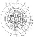
図1に示すように、本発明の第1の検討例に係る車輪支持装置200が支持する電動輪100は、ホイールディスク10と、ホイールハブ20と、等速ジョイント30と、ブレーキロータ40と、ブレーキキャリパ50と、インホイールモータ70と、タイヤ250とから構成される。<Firststudy example >
As shown in FIG. 1, the
インホイールモータ70は、ケース60と、モータ65と、プラネタリギヤ80と、オイルポンプ90と、シャフト110と、オイル通路(図示せず)とから構成される。 The in-
また、車輪支持装置200は、ダイナミックマスダンパ機構(図示せず)と、ボールジョイント160,170と、ナックル180と、アッパーアーム210と、ロアアーム220と、ショックアブソーバ(図示せず)とから構成される。 The
ホイールディスク10は、略カップ型形状を有し、ディスク部10Aとリム部10Bとからなる。そして、ホイールディスク10は、ホイールハブ20、ブレーキロータ40、ブレーキキャリパ50、およびインホイールモータ70を収納するようにしてもよい。ホイールディスク10は、ディスク部10Aをホイール取り付け部22において、ボルトあるいはナット(図示せず)によってホイールハブ20に締結することによりホイールハブ20と連結される。ホイールハブ20は、等速ジョイント30を内蔵し、その内蔵した等速ジョイント30を介してシャフト110に連結される。そして、ホイールハブ20は、ベアリング11,12によってナックル180に回転自在に支持される。タイヤ250は、ホイールディスク10のリム部10Bの外縁に固定される。 The
等速ジョイント30は、インナー31と、ボール32とを含む。インナー31は、シャフト110に嵌合される。ボール32は、シャフト110の回転軸方向に設けられたホイールハブ20の溝とインナー31の溝とに噛合っており、シャフト110の回転に伴ってホイールハブ20を回転させる。また、ボール32は、ホイールハブ20およびインナー31に設けられた溝に沿ってシャフト110の回転軸方向に移動可能である。なお、等速ジョイント30は、インホイールモータ70の動力をホイール10に伝達する動力伝達機構であれば特に限定されるものではないが、たとえば、複数の円盤等を用いてインホイールモータ側とホイール側とがどの方向にも偏心可能に結合される、いわゆるフレキシブルカップリングを用いてもよい。 The constant velocity joint 30 includes an inner 31 and a
ブレーキロータ40は、内周端がボルト24,26によってホイールハブ20の外周端に固定され、外周端がブレーキキャリパ50内を通過するように配置される。ブレーキキャリパ50は、ナックル180に固定される。そして、ブレーキキャリパ50は、ブレーキピストン51と、ブレーキパッド52,53とを含む。ブレーキパッド52,53は、ブレーキロータ40の外周端を挟み込む。 The
開口部50Aからブレーキオイルが供給されると、ブレーキピストン51は、図1において紙面右側へ移動し、ブレーキパッド52を紙面右側へ押す。ブレーキパッド52がブレーキピストン51によって紙面右側へ移動すると、それに応答してブレーキパッド53が紙面左側へ移動する。これにより、ブレーキパッド52,53は、ブレーキロータ40の外周端を挟み込み、電動輪100にブレーキがかけられる。 When brake oil is supplied from the
ケース60は、図1において、ホイールハブ20の紙面左側に配置される。そして、ケース60は、モータ65と、プラネタリギヤ80と、オイルポンプ90と、シャフト110と、オイル通路とを収納する。 The
モータ65は、ステータコア71と、ステータコイル72と、ロータ73とを含む。ステータコア71は、ケース60に固定される。ステータコイル72は、ステータコア71に巻回される。モータ65が三相モータである場合、ステータコイル72は、U相コイル、V相コイルおよびW相コイルからなる。ロータ73は、ステータコア71およびステータコイル72の内周側に配置される。
プラネタリギヤ80は、サンギヤ軸81と、サンギヤ82と、ピニオンギヤ83と、プラネタリキャリア84と、リングギヤ85と、ピン86とを含む。サンギヤ軸81は、モータ65のロータ73に連結される。そして、サンギヤ軸81は、ベアリング15,16により回転自在に支持される。サンギヤ82は、サンギヤ軸81に連結される。 Planetary gear 80 includes a
ピニオンギヤ83は、サンギヤ82と噛合い、ピン86の外周に配設されたベアリングにより回転自在に支持される。プラネタリキャリア84は、ピニオンギヤ83に連結され、シャフト110に接続される。そして、プラネタリキャリア84およびプラネタリキャリア84に接続されるシャフト110は、ベアリング13,14により回転自在に支持される。リングギヤ85は、ケース60に固定される。ピン86は、プラネタリキャリア84に支持される。 The pinion gear 83 meshes with the
オイルポンプ90は、インホイールモータ70のホイールハブ20側の端部に、シャフト110に接続されて設けられる。シャフト110は、上述したように等速ジョイント30のインナー31およびプラネタリキャリア84接続され、ベアリング13,14によって回転自在に支持される。 The oil pump 90 is provided at the end of the in-
オイル通路は、ケース60に設けられる。オイル通路は、一方端がオイルポンプ90に連結され、他方端がオイル溜(図示せず)に挿入される。 The oil passage is provided in the
オイルポンプ90は、シャフト110の回転に伴なってオイル溜に溜まったオイルをオイル通路を介して汲み上げ、その汲み上げたオイルをケース60内で循環させる。ケース60の上部には、ケース60の内部の圧力を一定に維持するブリーザ装置400が設けられる。 The oil pump 90 pumps up the oil accumulated in the oil reservoir as the
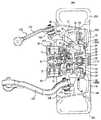
図2に示すように、ダイナミックマスダンパ機構300は、車両の上下方向に設けられる1対の弾性部材であるスプリング302,304から構成される。ダイナミックマスダンパ機構300の中央部306は、インホイールモータ70のケース60の外周側面に取り付けられる。本検討例において、たとえば、ダイナミックマスダンパ機構300の中央部306は、ケース60の車両の後方側でかつインホイールモータ70の回転軸と同じ高さになる位置に取り付けられる。そして、ダイナミックマスダンパ機構300の上部310は、ナックル180(180A)に接続される。上部310と中央部306とは、スプリング302を介して接続される。ダイナミックマスダンパ機構300の下部312は、ナックル180(180B)に接続される。下部312と中央部306とは、スプリング304を介して接続される。As shown in FIG. 2, the dynamic
また、下部312と中央部306とは、アブソーバ314を介して接続される。アブソーバ314は、シャフト316を含む。アブソーバ314は、シャフト316の上下の振動を抑制する。シャフト316の一方端336は、中央部306に接続される。中央部306を貫通するシャフト316は、ブッシュ308により水平方向の位置が制限される。また、アブソーバ314の下端は、ブッシュ326により水平方向の位置が制限される。なお、シャフト316の一方端336は、上部310に接続されてもよい。 The
ナックル180(180A)は、一方端がボールジョイント160に連結され、他方端がベアリング11,12を介してホイールハブ20に連結される。ナックル180(180B)の下部には、プレート182がボルトにより固定される。そして、プレート182には、ボールジョイント170が連結される。 The knuckle 180 (180A) has one end connected to the ball joint 160 and the other end connected to the
図3に示すように、アッパーアーム210およびロアアーム220は、車両の上下方向に配置される。アッパーアーム210は、一方端がボールジョイント160に連結され、他方端が車両の上下方向に回動可能に車体に固定される。ロアアーム220は、一方端がボールジョイント170に連結され、他方端が車両の上下方向に回動可能に車体に固定される。また、ロアアーム220は、ショックアブソーバを介して車体に連結される。これにより、電動輪100は、車体に懸架される。 As shown in FIG. 3, the
このように、アッパーアーム210およびロアアーム220は、車両の上下方向からそれぞれボールジョイント160,170を介してナックル180に連結される。 As described above, the
ナックル180には、ステアリングタイロッド(図示せず)の一方端が連結される。そして、ステアリングタイロッドは、車体のステアリング(ハンドル)からの回転力に応じて、車両の進行方向に対して右方向または左方向に電動輪100を回動する。 One end of a steering tie rod (not shown) is connected to the
アッパーアーム210およびロアアーム220は、車両の上下方向に回動自在に車体に固定され、ロアアーム220は、ショックアブソーバを介して車体に連結されるので、アッパーアーム210、ロアアーム220およびショックアブソーバは、サスペンションとして機能する。 The
ダイナミックマスダンパ機構300は、インホイールモータ70のケース60に固定される。また、ダイナミックマスダンパ機構300は、ナックル180に連結される。そして、ボールジョイント160,170によってサスペンションアーム(アッパーアーム210およびロアアーム220)をナックル180に連結することにより、車輪支持装置200は、電動輪100を車体に支持する。 The dynamic
すなわち、車輪支持装置200は、アッパーアーム210、ロアアーム220およびナックル180によってホイールディスク10およびホイールハブ20を回転可能に支持し、アッパーアーム210、ロアアーム220およびダイナミックマスダンパ機構300によってインホイールモータ70を車両の上下方向に振動可能に支持する。 That is, the
また、車両に搭載されたスイッチング回路(図示せず)によりステータコイル72に交流電流が供給されると、ロータ73が回転し、モータ65は、所定のトルクを出力する。そして、モータ65の出力トルクは、サンギヤ軸81を介してプラネタリギヤ80へ伝達される。プラネタリギヤ80は、サンギヤ軸81から受けた出力トルクをサンギヤ82およびピニオンギヤ83によって変更、つまり、変速(減速)してプラネタリキャリア84へ出力する。プラネタリキャリア84は、プラネタリギヤ80の出力トルクをシャフト110に伝達し、シャフト110は、等速ジョイント30を介して所定の回転数でホイールハブ20およびホイールディスク10を回転する。これにより、電動輪100は、所定の回転数で回転して、車両は走行する。 When an alternating current is supplied to the
車両の走行中に、電動輪100が路面状態等に応じて車両の上下方向に振動を受けると、ダンパーマスとなるインホイールモータ70によってダイナミックマスダンパ機構300のスプリング302,304は、車両の上下方向に伸縮する。スプリング302,304の伸縮により、電動輪100が路面から受ける力による振動と位相がずれたインホイールモータ70の上下方向の振動が発生する。つまり、ダイナミックマスダンパ機構300は、電動輪100の振動をインホイールモータ70の振動に変換する。このとき、車体には、電動輪100の振動と、電動輪100の振動とは位相がずれたインホイールモータ70の振動とを合成した振動が伝達される。電動輪100の振動とインホイールモータ70の振動とは位相がずれているため、電動輪100の振動の振幅は、位相がずれたインホイールモータ70の振動の振幅により低減される。すなわち、電動輪100の振動は、インホイールモータ70の振動によりアッパーアーム210およびロアアーム220を介して車体に伝達されにくくなる。 When the
インホイールモータ70は、等速ジョイント30を介して上下方向に振動する。具体的には、インホイールモータ70は、等速ジョイント30を回転中心として、車両の上下方向に円弧を描くように振動する。このとき、インホイールモータ70の水平方向の振動は、ダイナミックマスダンパ機構300に設けられるブッシュ308および326により吸収される。一方、スプリング304の伸縮により生じる、インホイールモータ70の上下方向の振動は、アブソーバ314により減衰される。 The in-
上述のようにして、タイヤ250からのバネ下入力が緩和される。すなわち、車両の走行中に電動輪100が路面状態等に応じて振動を受けると、サスペンションに設けられるショックアブソーバによって吸収し切れない振動がダイナミックマスダンパ機構300によって吸収される。ダイナミックマスダンパ機構300は、電動輪100が受けた振動によってインホイールモータ70を車両の上下方向に位相をずらせて振動させる。ダイナミックマスダンパ機構300は、結果的にバネ上である車体に大きな振動を伝えない。したがって、インホイールモータ70によって駆動される車輪を搭載した車両の乗り心地が向上する。 As described above, the unsprung input from the
車両の走行中は、インホイールモータ70の駆動に伴なってタイヤ250が回転することにより、路面に散在する石や砂、ゴミなどの異物等の飛び石が巻き上げられる。巻き上げられた飛び石は、車体側に設けられるホイールハウスの内面に跳ね返ってインホイールモータ70に衝突する可能性がある。特に、ダイナミックマスダンパ機構300が設けられるインホイールモータ70においては、等速ジョイント30のような動力伝達機構を有するため、インホイールモータ70の軸長がホイール10の幅よりも大きくなる場合がある。そのため、ケース60の一部がホイール10から車両の中央側に突出する。したがって、ホイールハウスの内面で跳ね返った飛び石は、ケース60の車両の中央側に突出する部位に衝突する。このとき、ケース60に設けられる部品がケース60の車両の中央側に突出する部位に設けられると、ホイールハウスの内面で跳ね返った飛び石により部品が破損する可能性がある。 While the vehicle is running, the
そこで、本検討例に係る部品の搭載構造において、ケース60に設けられる部品は、インホイールモータ70の回転軸よりも上方の位置であってかつインホイールモータ70とホイール10との間の位置に設けられる。そして、位置は、車両の幅方向におけるホイール10の内部である。なお、本検討例に係る部品の搭載構造が適用される部品は、ケース60に設けられる部品であれば特に限定されるものではないが、たとえば、ケース60の内部の圧力を一定に維持するブリーザ装置400である。Therefore, in the component mounting structure according to the presentstudy example , the component provided in the
ケース60の内部は、オイルを循環させるため、密封されると、ケース60内の圧力は、熱等の影響を受けるため、一定とならない。たとえば、ケース60内部において熱が発生すると、あるいは外部からケースが加熱されると、ケース内の空気などの気体は暖まる。ケース60内の気体が暖まると、気体は、膨張する。そのため、気体の膨張に伴なって、ケース60内の圧力が上昇する。圧力の高い状態が維持されると、ケース60内部に密封したオイルがシール部から漏れる等の問題が起こる。そのため、ケース60の上部には、ケース60内の圧力を抜いて圧力が一定になるように維持するブリーザ装置400が設けられている。なお、ブリーザ装置400は、ケース60の内部のオイルが出ないように好ましくはインホイールモータ70の回転軸よりも上方に設けられることが望ましい。 When the inside of the
なお、ホイールディスク10およびホイールハブ20は、「車輪」を構成する。さらに、ナックル180は、車輪(ホイールディスク10およびホイールハブ20)を回転可能に支持する「回転支持部材」を構成する。スプリング302,304は、車輪(ホイールディスク10およびホイールハブ20)およびインホイールモータ70の振動を減衰する「弾性部材」を構成する。 The
以上のような構造に基づく、本検討例に係る部品の搭載構造の作用について説明する。The operation of the component mounting structure according to the presentstudy example based on the above structure will be described.
インホイールモータ70が駆動すると、車両は走行状態となる。このとき、タイヤ250の回転に伴なって、路面に散在する飛び石が巻き上げられる。このとき、タイヤ250は、タイヤ250の車両の後方側に飛び石を巻き上げる。巻き上げられた飛び石は、ホイールハウスの内面で跳ね返る。跳ね返った飛び石の一部は、ブリーザ装置400に向けて飛散する。ブリーザ装置400に向かって飛散した飛び石は、ブリーザ装置400がホイール10とインホイールモータ70との間に設けられるため、タイヤ250に衝突する。そして、タイヤ250に衝突した飛び石は、ブリーザ装置400に衝突することなく、路面に落下する。 When the in-
以上のようにして、本検討例に係る部品の搭載構造によると、モータが車輪の幅よりも長い軸長を有する場合、ブリーザ装置は、モータの回転軸よりも上方の位置であってかつモータと車輪との間の位置に設けられる。位置は、車両の幅方向における車輪の内部である。モータが駆動して車両が走行状態になると、車輪は回転に伴なって飛び石を巻き上げる。このとき、車輪は、車輪の後方側に飛び石を巻き上げる。車輪により巻き上げられた飛び石は、ホイールハウスの内面で跳ね返る。ホイールハウスの内面で跳ね返った飛び石のうち、ブリーザ装置に向かって飛散する飛び石は、ブリーザ装置が車輪とモータとの間に設けられるため、車輪に衝突する。すなわち、車輪自体がブリーザ装置を飛び石の衝突から保護する。したがって、車輪が巻き上げる飛び石の衝突による破損を防止する部品の搭載構造を提供することができる。As described above, according to the component mounting structure according to the presentstudy example , when the motor has an axial length longer than the width of the wheel, the breather device is positioned above the rotating shaft of the motor and the motor. Between the wheel and the wheel. The position is inside the wheel in the width direction of the vehicle. When the motor is driven and the vehicle is in a running state, the wheels roll up the stepping stones as they rotate. At this time, the wheel rolls up a stepping stone on the rear side of the wheel. Stepping stones rolled up by wheels bounce off the inside of the wheelhouse. Of the stepping stones that bounce off the inner surface of the wheel house, stepping stones that fly toward the breather device collide with the wheels because the breather device is provided between the wheels and the motor. That is, the wheels themselves protect the breather device from stepping stone collisions. Therefore, it is possible to provide a component mounting structure that prevents damage caused by the collision of the stepping stones rolled up by the wheels.
なお、本検討例に係る部品は、たとえば、ブリーザ装置400として説明したが、ケース60に設けられる部品であれば、特に限定されるものではない。たとえば、インホイールモータ70の内部に設けられ、温度を検知するセンサ、いわゆるサーミスタやインホイールモータ70の回転数を検知するセンサ、いわゆるレゾルバに接続されるコネクタであってもよい。In addition, although the component which concerns on thisstudy example demonstrated as the
また、ブリーザ装置400は、好ましくは、ブリーザ装置400から出されたオイルがブレーキキャリパ50あるいはブレーキディスク40に付着しないような位置に設けることが望ましい。このようにすると、ブリーザ装置400から出されたオイルがブレーキキャリパ50あるいはブレーキロータ40に付着することによるブレーキパッド52,53における摩擦抵抗の減少、すなわち、制動力の悪化を防止することができる。 The
<第2の検討例>
以下、本発明の第2の検討例に係る部品の搭載構造について説明する。本検討例に係る部品の搭載構造は、上述の第1の検討例に係るブリーザ装置400が設けられる電動輪100の構成と比較して、ブリーザ装置400と異なる位置にブリーザ装置410が設けられる点が異なる。それ以外の構成は、上述の第1の検討例に係るブリーザ装置400が設けられる電動輪100の構成と同じ構成である。それらについては同じ参照符号が付してある。それらの機能も同じである。したがって、それらについての詳細な説明はここでは繰り返さない。<Secondstudy example >
The component mounting structure according to the secondstudy example of the present invention will be described below. The component mounting structure according to the presentstudy example is such that the
図4に示すように、本検討例に係るブリーザ装置410は、車両の幅方向における位置がホイール10の外部になるように設けられる。また、図5に示すように、ブリーザ装置410は、インホイールモータ70の回転軸よりも上方の位置であってかつ車両の前方側の位置に設けられる。As shown in FIG. 4, the
以上のような構造に基づく、本検討例に係る部品の搭載構造の作用について説明する。The operation of the component mounting structure according to the presentstudy example based on the above structure will be described.
インホイールモータ70が駆動すると、車両は走行状態となる。このとき、タイヤ250の回転に伴なって、路面に散在する飛び石が巻き上げられる。このとき、タイヤ250は、タイヤ250の車両の後方側にと飛び石を巻き上げる。巻き上げられた飛び石は、ホイールハウスの内面で跳ね返る。跳ね返った飛び石は、インホイールモータ70の車両の内側に突出した部位のうちインホイールモータ70の回転軸よりも車両後方側に衝突する。そして、インホイールモータ70に衝突した飛び石は、路面に落下する。すなわち、インホイールモータ70の回転軸よりも車両前方側に設けられるブリーザ装置410に衝突することなく、飛び石は路面に落下する。 When the in-
以上のようにして、本検討例に係る部品の搭載構造によると、モータが車輪の幅よりも長い軸長を有する場合、ブリーザ装置は、モータの回転軸よりも上方の位置であってかつ車両の前方側の位置に設けられる。位置は、車両の幅方向における車輪の外部である。モータが駆動して車両が走行状態になると、車輪は回転に伴なって飛び石を巻き上げる。このとき、車輪は、車輪の後方側に飛び石を巻き上げる。車輪により巻き上げられた飛び石は、ホイールハウスの内面で跳ね返る。ホイールハウスの内面で跳ね返った飛び石は、モータの筐体において、モータの回転軸よりも車両の後方側の部位に衝突する。すなわち、ブリーザ装置をモータの回転軸よりも車両の前方側に設けることにより、車輪から車両の内側に突出したモータの部位であっても、飛び石の衝突を回避することができる。したがって、車輪が巻き上げる飛び石の衝突による破損を防止する部品の搭載構造を提供することができる。As described above, according to the component mounting structure according to the presentstudy example , when the motor has an axial length longer than the width of the wheel, the breather device is positioned above the rotating shaft of the motor and the vehicle. Is provided at a position on the front side. The position is outside the wheel in the width direction of the vehicle. When the motor is driven and the vehicle is in a running state, the wheels roll up the stepping stones as they rotate. At this time, the wheel rolls up a stepping stone on the rear side of the wheel. Stepping stones rolled up by wheels bounce off the inside of the wheelhouse. The stepping stones that bounce off the inner surface of the wheel house collide with the rear side of the vehicle with respect to the rotating shaft of the motor in the motor housing. That is, by providing the breather device on the front side of the vehicle with respect to the rotating shaft of the motor, it is possible to avoid the collision of the stepping stones even at the motor part protruding from the wheel to the inside of the vehicle. Therefore, it is possible to provide a component mounting structure that prevents damage caused by the collision of the stepping stones rolled up by the wheels.
<実施の形態>
以下、本発明の実施の形態に係る部品の搭載構造について説明する。本実施の形態に係る部品の搭載構造は、上述の第2の検討例に係るブリーザ装置400が設けられる電動輪100の構成と比較して、ブリーザ装置410と車両の前後方向で異なる位置にブリーザ装置が設けられる点およびブリーザ装置に遮蔽板が設けられる点が異なる。それ以外の構成は、上述の第1の検討例に係るブリーザ装置410が設けられる電動輪100の構成と同じ構成である。それらについては同じ参照符号が付してある。それらの機能も同じである。したがって、それらについての詳細な説明はここでは繰り返さない。<Implementation of the form>
The following describes a structure for mounting a component according to theimplementation of the embodiment of the present invention. Compared with the configuration of the motor-driven
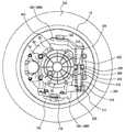
図6に示すように、本実施の形態に係るブリーザ装置420は、インホイールモータ70の回転軸よりも上方の位置であってかつ車両の後方側の位置に設けられる。また、ブリーザ装置420は、車両の幅方向における位置がホイール10の外部になるように設けられる。そして、ブリーザ装置420には、図7(A)および図7(B)に示すように、ブリーザ装置420よりも車両の幅方向の車両の中央側およびブリーザ装置420よりも後方側に、外部からの異物との接触を回避する遮蔽板460が設けられる。なお、遮蔽板460は、ブリーザ装置420が外部からの異物との接触を回避できる部材、形状であれば特に限定されるものではない。 As shown in FIG. 6,
以上のような構造に基づく、本実施の形態に係る部品の搭載構造の作用について説明する。 The operation of the component mounting structure according to the present embodiment based on the above structure will be described.
インホイールモータ70が駆動すると、車両は走行状態となる。このとき、タイヤ250の回転に伴なって、路面に散在する飛び石が巻き上げられる。このとき、タイヤ250は、タイヤ250の車両の後方側に飛び石を巻き上げる。巻き上げられた飛び石は、ホイールハウスの内面で跳ね返る。ホイールハウスの内面で跳ね返った飛び石の一部は、ブリーザ装置420に向かって飛散する。ブリーザ装置420に向かって飛散した飛び石は、遮蔽板460衝突する。そして、遮蔽板460に衝突した飛び石は、ブリーザ装置420に衝突することなく、路面に落下する。 When the in-
なお、好ましくは、ブリーザ装置420を囲う遮蔽板460には、車両の後方側に切り欠き部470を設けることが望ましい。このようにすると、ブリーザ装置420が設けられる取り付け部480に飛び石や水の蓄積を抑制することができる。そのため、ブリーザ装置420の機能は低下しない。 Preferably, the shielding
また、このとき、切り欠き部470は、ブリーザ装置420と車両の幅方向でずらした(オフセットした)位置に設けることが望ましい。このようにすると、車両の後方側から飛散する飛び石が切り欠き部470を通ってブリーザ装置420に衝突することを回避することができる。 At this time, it is desirable to provide the
以上のようにして、本実施の形態に係る部品の搭載構造によると、モータが車輪の幅よりも長い軸長を有する場合、ブリーザ装置は、モータの回転軸よりも上方の位置であってかつ車両の後方側の位置に設けられる。位置は、車両の幅方向における車輪の外部である。ブリーザ装置には、ブリーザ装置よりも幅方向の車両中央側およびブリーザ装置よりも後方側に、車輪が巻き上げる飛び石の異物との接触を回避する遮蔽板が設けられる。モータが駆動して車両が走行状態になると、車輪は回転に伴なって飛び石を巻き上げる。このとき、車輪は、車輪の後方側に飛び石を巻き上げる。車輪により巻き上げられた飛び石は、ホイールハウスの内面で跳ね返る。ホイールハウスの内面で跳ね返った飛び石のうちブリーザ装置に向かって飛散する飛び石は、モータに設けられる遮蔽板に衝突する。すなわち、遮蔽板により飛び石がブリーザ装置に衝突することを回避することができる。したがって、車輪が巻き上げる飛び石の衝突による破損を防止する部品の搭載構造を提供することができる。 As described above, according to the component mounting structure according to the present embodiment, when the motor has an axial length longer than the width of the wheel, the breather device is positioned above the rotational axis of the motor and It is provided at a position on the rear side of the vehicle. The position is outside the wheel in the width direction of the vehicle. The breather device is provided with a shielding plate for avoiding contact with the stepping stones rolled up by the wheels on the vehicle center side in the width direction of the breather device and on the rear side of the breather device. When the motor is driven and the vehicle is in a running state, the wheels roll up the stepping stones as they rotate. At this time, the wheel rolls up a stepping stone on the rear side of the wheel. Stepping stones rolled up by wheels bounce off the inside of the wheelhouse. Of the stepping stones that bounced off the inner surface of the wheel house, stepping stones scattered toward the breather device collide with a shielding plate provided in the motor. That is, the stepping stone can be prevented from colliding with the breather device by the shielding plate. Therefore, it is possible to provide a component mounting structure that prevents damage caused by the collision of the stepping stones rolled up by the wheels.
今回開示された実施の形態はすべての点で例示であって制限的なものではないと考えられるべきである。本発明の範囲は上記した説明ではなくて特許請求の範囲によって示され、特許請求の範囲と均等の意味および範囲内でのすべての変更が含まれることが意図される。 The embodiment disclosed this time should be considered as illustrative in all points and not restrictive. The scope of the present invention is defined by the terms of the claims, rather than the description above, and is intended to include any modifications within the scope and meaning equivalent to the terms of the claims.
10 ホイールディスク、10A ディスク部、10B リム部、11,12,13,14,15,16 ベアリング、20 ホイールハブ、22 ホイール取り付け部、24,26 ボルト、30 等速ジョイント、31 インナー、32 ボール、40 ブレーキロータ、50 ブレーキキャリパ、50A 開口部、51 ブレーキピストン、52,53 ブレーキパッド、60 ケース、65 モータ、70 インホイールモータ、71 ステータコア、72 ステータコイル、73 ロータ、80 プラネタリギア、81 サンギヤ軸、82 サンギヤ、83 ピニオンギヤ、84 プラネタリキャリア、85 リングギヤ、86 ピン、90 オイルポンプ、100 電動輪、160,170 ボールジョイント、180A,180B ナックル、182 プレート、200 車輪支持装置、210 アッパーアーム、220 ロアアーム、250 タイヤ、300 ダイナミックマスダンパ機構、302,304 スプリング、306 中央部、308,326 ブッシュ、310 上部、312 下部、314 アブソーバ、316 シャフト、336 一方端、400,410,420 ブリーザ装置、460 遮蔽板、470 切り欠き部、480 取り付け部。 10 wheel disc, 10A disc portion, 10B rim portion, 11, 12, 13, 14, 15, 16 bearing, 20 wheel hub, 22 wheel mounting portion, 24, 26 bolt, 30 constant velocity joint, 31 inner, 32 ball, 40 brake rotor, 50 brake caliper, 50A opening, 51 brake piston, 52, 53 brake pad, 60 case, 65 motor, 70 in-wheel motor, 71 stator core, 72 stator coil, 73 rotor, 80 planetary gear, 81 sun gear shaft , 82 Sun gear, 83 Pinion gear, 84 Planetary carrier, 85 Ring gear, 86 pin, 90 Oil pump, 100 Electric wheel, 160, 170 Ball joint, 180A, 180B Knuckle, 182 Plate, 200 Wheel support device, 210 Upper arm, 220 Lower arm, 250 Tire, 300 Dynamic mass damper mechanism, 302, 304 Spring, 306 Central part, 308, 326 Bush, 310 Upper part, 312 lower part, 314 Absorber, 316 shaft, 336 One end, 400, 410, 420 breather device, 460 shielding plate, 470 notch, 480 attachment.
Claims (9)
Translated fromJapanese前記部品は、前記モータの回転軸よりも上方であってかつ車両の後方側の位置に設けられ、
前記位置は、前記車両の幅方向における前記車輪の外部であって、
前記部品には、前記部品よりも前記幅方向の車両中央側および前記部品よりも前記後方側に、外部からの異物との接触を回避する遮蔽手段が設けられる、インホイールモータに設けられる部品の搭載構造。A mounting structure of components provided on an outer peripheral portion of a housing of an in-wheel motor having a motor that generates a driving force of the wheel in the wheel, wherein at least a part of thehousing of the in-wheel motor protrudes from the wheel,
The component is provided above the rotating shaft of the motor and at a position on the rear side of the vehicle.
The position is outside the wheel in the width direction of the vehicle,
The component provided in the in-wheel motor is provided with shielding means for avoiding contact with foreign matter from the outside, on the vehicle center side in the width direction than the component and on the rear side from the component. Mounting structure.
前記ダイナミックマスダンパ機構は、前記回転支持部材に取付けられる、請求項1〜6のいずれかに記載のインホイールモータに設けられる部品の搭載構造。The wheel is provided with the wheel attached to the motor, adynamic mass damper mechanism that attenuates vibration of the motor, and a rotation support member that rotatably supports the wheel connected to the output shaft of the motor. And
Thedynamic mass damper mechanism, said mounted to the rotating support member, a structure for mounting acomponent provided in-wheel motor according toany one of claims1 to 6.
前記車輪と前記出力軸とを連結する等速ジョイントと、
前記等速ジョイントを回転可能に支持するナックルとを含み、
前記ダイナミックマスダンパ機構は、
前記筐体と前記回転支持部材とを接続する弾性部材と、
前記弾性部材の伸縮を減衰するアブソーバとを含む、請求項7に記載のインホールモータに設けられる部品の搭載構造。The rotation support member is
A constant velocity joint connecting the wheel and the output shaft;
A knuckle that rotatably supports the constant velocity joint,
The dynamic mass damper mechanism is
An elastic member connecting the casing and the rotation support member;
Thecomponent mounting structureprovided in thein-hole motor according to claim7 , furthercomprising an absorber that attenuates expansion and contraction of the elastic member .
前記板部材には、前記後方側であって、かつ、前記部品と前記車両の幅方向でオフセットした位置に切り欠き部が設けられる、請求項1〜8のいずれかに記載のインホイールモータに設けられる部品の搭載構造。The in-wheel motor according to any one of claims 1 to 8, wherein the plate member is provided with a notch on the rear side and at a position offset in the width direction of the component and the vehicle. The mounting structure of the parts to be provided.
Priority Applications (8)
| Application Number | Priority Date | Filing Date | Title |
|---|---|---|---|
| JP2004146074AJP4276579B2 (en) | 2004-05-17 | 2004-05-17 | Mounting structure of components installed in in-wheel motor |
| CNB2005800157416ACN100526108C (en) | 2004-05-17 | 2005-05-16 | component mounting structure |
| CNA2008102104279ACN101423021A (en) | 2004-05-17 | 2005-05-16 | Mounting structure of part |
| PCT/JP2005/009296WO2005110796A1 (en) | 2004-05-17 | 2005-05-16 | Mounting structure of part |
| DE112005003816.5TDE112005003816B4 (en) | 2004-05-17 | 2005-05-16 | Radinterner engine |
| US11/579,417US7958959B2 (en) | 2004-05-17 | 2005-05-16 | Mounting structure for a part provided to an enclosure of an in-wheel motor |
| DE112005001122.4TDE112005001122B8 (en) | 2004-05-17 | 2005-05-16 | A fixing structure for a part provided at an outer peripheral portion of a worm-motor enclosure |
| US12/222,030US8157036B2 (en) | 2004-05-17 | 2008-07-31 | Mounting structure of part |
Applications Claiming Priority (1)
| Application Number | Priority Date | Filing Date | Title |
|---|---|---|---|
| JP2004146074AJP4276579B2 (en) | 2004-05-17 | 2004-05-17 | Mounting structure of components installed in in-wheel motor |
Publications (2)
| Publication Number | Publication Date |
|---|---|
| JP2005324722A JP2005324722A (en) | 2005-11-24 |
| JP4276579B2true JP4276579B2 (en) | 2009-06-10 |
Family
ID=35394066
Family Applications (1)
| Application Number | Title | Priority Date | Filing Date |
|---|---|---|---|
| JP2004146074AExpired - Fee RelatedJP4276579B2 (en) | 2004-05-17 | 2004-05-17 | Mounting structure of components installed in in-wheel motor |
Country Status (5)
| Country | Link |
|---|---|
| US (2) | US7958959B2 (en) |
| JP (1) | JP4276579B2 (en) |
| CN (2) | CN101423021A (en) |
| DE (2) | DE112005001122B8 (en) |
| WO (1) | WO2005110796A1 (en) |
Families Citing this family (78)
| Publication number | Priority date | Publication date | Assignee | Title |
|---|---|---|---|---|
| JP4276579B2 (en)* | 2004-05-17 | 2009-06-10 | トヨタ自動車株式会社 | Mounting structure of components installed in in-wheel motor |
| JP2006188153A (en) | 2005-01-06 | 2006-07-20 | Toyota Motor Corp | In-wheel motor |
| WO2007026199A1 (en)* | 2005-08-31 | 2007-03-08 | Toyota Jidosha Kabushiki Kaisha | In-wheel suspension |
| JP4965131B2 (en)* | 2006-01-27 | 2012-07-04 | トヨタ自動車株式会社 | In-wheel motor |
| JP5133572B2 (en)* | 2006-02-02 | 2013-01-30 | 株式会社ブリヂストン | Mounting method and mounting structure of dynamic vibration absorber and in-wheel motor |
| FR2898833B1 (en)* | 2006-03-23 | 2008-12-05 | Conception & Dev Michelin Sa | GROUND LINK FOR VEHICLE |
| JP4501909B2 (en)* | 2006-08-11 | 2010-07-14 | トヨタ自動車株式会社 | In-wheel motor structure |
| JP5052084B2 (en)* | 2006-09-19 | 2012-10-17 | Ntn株式会社 | Axle unit with in-wheel motor built-in sensor |
| JP2008207663A (en)* | 2007-02-26 | 2008-09-11 | Toyota Motor Corp | Wheel mounting structure |
| JP5262062B2 (en)* | 2007-10-22 | 2013-08-14 | トヨタ自動車株式会社 | Breather layout |
| JP5369763B2 (en)* | 2009-03-02 | 2013-12-18 | トヨタ自動車株式会社 | Breather mechanism for in-wheel motor |
| JP5141614B2 (en)* | 2009-03-25 | 2013-02-13 | アイシン精機株式会社 | In-wheel motor unit |
| DE102009035176A1 (en) | 2009-07-29 | 2011-02-10 | Daimler Ag | Wheel hub drive for motor vehicle e.g. passenger car, has disk brake system including brake caliper that is arranged in recess, where recess is provided in stator of electric machine |
| DE102010049610A1 (en)* | 2009-12-07 | 2011-06-09 | Schaeffler Technologies Gmbh & Co. Kg | Electric drive unit for a motor vehicle |
| WO2011114008A1 (en)* | 2010-03-17 | 2011-09-22 | Societe De Technologie Michelin | Motor-driven hub including an electric traction machine |
| JP5690153B2 (en)* | 2011-01-21 | 2015-03-25 | Ntn株式会社 | In-wheel motor drive device |
| JP2012171428A (en)* | 2011-02-18 | 2012-09-10 | Ntn Corp | In-wheel motor driving apparatus |
| KR101197005B1 (en) | 2011-02-21 | 2012-11-02 | 현대위아 주식회사 | Device for driving in-wheel motor for electric vehicle |
| CN103415992B (en)* | 2011-02-25 | 2016-07-27 | Ntn株式会社 | Electric automobile |
| DE102011005617A1 (en)* | 2011-03-16 | 2012-09-20 | Zf Friedrichshafen Ag | Drive device for driving wheel for electrically driven vehicle, comprises electric machine and planetary gear, whose sun gear forms drive of planetary gear, where annulus gear of planetary gear is coupled to bearing pedestal |
| KR101301754B1 (en)* | 2011-05-23 | 2013-08-29 | 현대모비스 주식회사 | In-wheel driving apparatus |
| US20140066248A1 (en)* | 2011-05-23 | 2014-03-06 | Honda Motor Co., Ltd. | Drive device for vehicle with electric motor |
| JP5792015B2 (en)* | 2011-09-27 | 2015-10-07 | Ntn株式会社 | In-wheel motor drive device |
| EP2767732A4 (en)* | 2011-10-14 | 2015-03-04 | Toyota Motor Co Ltd | POWER TRANSMISSION DEVICE |
| KR101294124B1 (en)* | 2011-10-21 | 2013-08-08 | 주식회사 만도 | In wheel motor system |
| KR101278914B1 (en)* | 2012-01-09 | 2013-06-26 | 주식회사 만도 | Mounting structure of in wheel motor system |
| JP5872360B2 (en)* | 2012-03-30 | 2016-03-01 | 本田技研工業株式会社 | Electric vehicle |
| JP5872358B2 (en)* | 2012-03-30 | 2016-03-01 | 本田技研工業株式会社 | Electric vehicle |
| GB2487872B (en)* | 2012-05-09 | 2012-12-26 | Protean Electric Ltd | An electric motor or generator system |
| JP5932582B2 (en) | 2012-09-12 | 2016-06-08 | Ntn株式会社 | In-wheel motor drive suspension structure |
| JP6195432B2 (en)* | 2012-10-03 | 2017-09-13 | Ntn株式会社 | In-wheel motor drive device |
| JP6192919B2 (en)* | 2012-11-02 | 2017-09-06 | Ntn株式会社 | In-wheel motor drive device |
| US9561715B2 (en)* | 2012-11-16 | 2017-02-07 | Deere & Company | Wheel hub with electric motor |
| EP2993066B1 (en)* | 2013-04-30 | 2018-09-05 | Nissan Motor Co., Ltd | Suspension device for in-wheel motor driven wheel |
| JP2015063266A (en)* | 2013-09-26 | 2015-04-09 | Ntn株式会社 | Drive device for wheel |
| JP6313610B2 (en)* | 2014-02-27 | 2018-04-18 | Ntn株式会社 | CONNECTION STRUCTURE OF IN-WHEEL MOTOR DRIVE DEVICE AND DAMPER AND SUSPENSION DEVICE PROVIDED WITH THIS CONNECTION |
| US10059162B2 (en)* | 2014-06-27 | 2018-08-28 | Nissan Motor Co., Ltd. | Unsprung power supply apparatus for in-wheel motor vehicle |
| JP6604711B2 (en) | 2014-08-20 | 2019-11-13 | Ntn株式会社 | Breather structure of in-wheel motor drive device and in-wheel motor drive device having this breather structure |
| US10300760B1 (en) | 2015-03-18 | 2019-05-28 | Apple Inc. | Fully-actuated suspension system |
| WO2016201705A1 (en)* | 2015-06-19 | 2016-12-22 | Robert Bosch Gmbh | Electric vehicle and driving system for electric vehicle |
| DE202016001998U1 (en)* | 2016-03-24 | 2016-06-09 | Mci (Mirror Controls International) Netherlands B.V. | Retrospective adjustment device |
| JP6918459B2 (en)* | 2016-04-06 | 2021-08-11 | Ntn株式会社 | Wiring structure of in-wheel motor power line and in-wheel motor drive |
| CN105922859A (en)* | 2016-06-18 | 2016-09-07 | 苏州埃威特新能源科技有限公司 | Wheel edge driving system |
| RU2633129C1 (en)* | 2016-08-24 | 2017-10-11 | Общество с ограниченной ответственностью "Полимагнит Санкт-Петербург" | Vehicle motor wheel and vehicle with such motor wheel |
| JP7079582B2 (en)* | 2016-09-21 | 2022-06-02 | Ntn株式会社 | Wheel bearing device with auxiliary power unit and its auxiliary power unit |
| JP6976083B2 (en)* | 2016-09-21 | 2021-12-01 | Ntn株式会社 | Vehicle power assist system and vehicle driven wheel regeneration system |
| JP6823418B2 (en)* | 2016-09-30 | 2021-02-03 | Ntn株式会社 | In-wheel motor drive |
| JP6823417B2 (en)* | 2016-09-30 | 2021-02-03 | Ntn株式会社 | In-wheel motor drive |
| JP6125083B1 (en)* | 2016-10-17 | 2017-05-10 | Ntn株式会社 | In-wheel motor drive device |
| US10814690B1 (en) | 2017-04-18 | 2020-10-27 | Apple Inc. | Active suspension system with energy storage device |
| JP2020518514A (en) | 2017-05-08 | 2020-06-25 | アップル インコーポレイテッドApple Inc. | Active suspension system |
| JP6760198B2 (en)* | 2017-05-16 | 2020-09-23 | トヨタ自動車株式会社 | Non-steering drive wheel suspension device with built-in in-wheel motor |
| DE102017208554A1 (en)* | 2017-05-19 | 2018-11-22 | Bayerische Motoren Werke Aktiengesellschaft | Wheel suspension for an at least slightly actively steerable rear wheel of a two-lane vehicle, axle with a suspension and vehicle with a suspension |
| US10899340B1 (en) | 2017-06-21 | 2021-01-26 | Apple Inc. | Vehicle with automated subsystems |
| US11173766B1 (en) | 2017-09-07 | 2021-11-16 | Apple Inc. | Suspension system with locking structure |
| US10906370B1 (en) | 2017-09-15 | 2021-02-02 | Apple Inc. | Active suspension system |
| US11124035B1 (en) | 2017-09-25 | 2021-09-21 | Apple Inc. | Multi-stage active suspension actuator |
| US10960723B1 (en) | 2017-09-26 | 2021-03-30 | Apple Inc. | Wheel-mounted suspension actuators |
| CA3081697C (en)* | 2017-11-02 | 2023-11-28 | Clark Equipment Company | Loader suspension |
| CN108502040B (en)* | 2018-05-30 | 2023-09-08 | 深圳市优必选科技有限公司 | Robot and chassis and suspension system thereof |
| US11285773B1 (en) | 2018-09-12 | 2022-03-29 | Apple Inc. | Control system |
| US11634167B1 (en) | 2018-09-14 | 2023-04-25 | Apple Inc. | Transmitting axial and rotational movement to a hub |
| US11345209B1 (en) | 2019-06-03 | 2022-05-31 | Apple Inc. | Suspension systems |
| CN114025972B (en)* | 2019-06-28 | 2023-04-21 | 瑞翼汽车有限公司 | Apparatus and method for dual arm suspension and in-wheel steering |
| US11938922B1 (en) | 2019-09-23 | 2024-03-26 | Apple Inc. | Motion control system |
| US11179991B1 (en) | 2019-09-23 | 2021-11-23 | Apple Inc. | Suspension systems |
| EP4096942A4 (en) | 2020-01-28 | 2024-04-17 | Ree Automotive Ltd | WHEEL SUSPENSION SYSTEM WITH ECCENTRIC ARM IN RELATION TO THE WHEEL |
| US11707961B1 (en) | 2020-04-28 | 2023-07-25 | Apple Inc. | Actuator with reinforcing structure for torsion resistance |
| US11828339B1 (en) | 2020-07-07 | 2023-11-28 | Apple Inc. | Vibration control system |
| US12017499B2 (en)* | 2021-05-25 | 2024-06-25 | Hyundai Mobis Co., Ltd. | Suspension device for in-wheel motor |
| US12017498B2 (en) | 2021-06-07 | 2024-06-25 | Apple Inc. | Mass damper system |
| KR20230011139A (en)* | 2021-07-13 | 2023-01-20 | 현대모비스 주식회사 | Wheel structure including hub bearing and vehicle including the same |
| KR102576319B1 (en) | 2021-08-17 | 2023-09-12 | 현대모비스 주식회사 | Disk brake apparatus of in wheel driven system |
| US12409692B2 (en)* | 2022-02-03 | 2025-09-09 | Hyundai Mobis Co., Ltd. | Corner module apparatus for vehicle |
| US12251973B2 (en) | 2022-06-10 | 2025-03-18 | Apple Inc. | Vibration absorber |
| WO2024150253A1 (en)* | 2023-01-13 | 2024-07-18 | Tvs Motor Company Limited | A hub motor assembly |
| US12168375B1 (en) | 2023-01-26 | 2024-12-17 | Apple Inc. | Motion control system |
| CN116238276B (en)* | 2023-03-15 | 2024-08-13 | 艾德斯汽车电机无锡有限公司 | Swing arm assembly arrangement structure of automobile with hub motor |
Family Cites Families (63)
| Publication number | Priority date | Publication date | Assignee | Title |
|---|---|---|---|---|
| JP2554697B2 (en)* | 1988-03-29 | 1996-11-13 | 新日本製鐵株式会社 | Electric vehicle motor cooling system |
| US5127485A (en)* | 1988-06-29 | 1992-07-07 | Aisin Aw Co., Ltd. | Electric motorized wheel with integral motorized cooling oil pump |
| JP2769323B2 (en)* | 1988-06-29 | 1998-06-25 | アイシン・エィ・ダブリュ株式会社 | Motor drive device with reduction gear and electric vehicle |
| US5163528A (en) | 1990-11-20 | 1992-11-17 | Aisun Aw Co., Ltd. | Wheel motor provided with a reduction gear |
| JP2849202B2 (en)* | 1990-11-20 | 1999-01-20 | アイシン・エイ・ダブリュ株式会社 | Wheel motor with reduction gear |
| JPH04185263A (en)* | 1990-11-20 | 1992-07-02 | Aisin Aw Co Ltd | Cooling apparatus of wheel motor |
| JP2849201B2 (en)* | 1990-11-20 | 1999-01-20 | アイシン・エイ・ダブリュ株式会社 | Wheel motor with reduction gear |
| US5150763A (en)* | 1991-04-24 | 1992-09-29 | Aisin Aw Co., Ltd. | Wiring and piping arrangement for a vehicle motor |
| US5180180A (en)* | 1991-04-24 | 1993-01-19 | Aisin Aw Co., Ltd. | Wheel supporting apparatus |
| US5087229A (en)* | 1991-05-06 | 1992-02-11 | General Motors Corporation | Independently suspended steerable motor wheel apparatus |
| DE4134240C2 (en)* | 1991-10-16 | 1995-12-14 | Mannesmann Ag | Steering support for a non-track-bound vehicle |
| JP3032993B2 (en)* | 1991-10-16 | 2000-04-17 | 株式会社東京アールアンドデー | Electric wheel cooling system |
| US5382854A (en)* | 1992-07-29 | 1995-01-17 | Kabushikikaisha Equos Research | Electrical motor drive apparatus with planetary gearing |
| JP2545733B2 (en) | 1993-09-17 | 1996-10-23 | 環境庁国立環境研究所長 | Electric vehicle drive |
| US5472059A (en) | 1994-02-15 | 1995-12-05 | Dana Corporation | Wheel end assembly |
| JP2892957B2 (en)* | 1994-12-09 | 1999-05-17 | 本田技研工業株式会社 | Motor with reduction gear |
| JP2965877B2 (en)* | 1994-11-15 | 1999-10-18 | 本田技研工業株式会社 | Motor with reduction gear |
| JPH09132040A (en)* | 1995-11-10 | 1997-05-20 | Honda Motor Co Ltd | Wheel motor with reduction gear |
| JPH09142160A (en)* | 1995-11-22 | 1997-06-03 | Uchihama Kasei Kk | Damage preventive structure for on-vehicle molding |
| JPH09195744A (en) | 1996-01-17 | 1997-07-29 | Toyota Motor Corp | Oil filter mounting structure |
| JP3604023B2 (en) | 1996-03-29 | 2004-12-22 | スズキ株式会社 | Electric vehicle |
| CH691052A5 (en) | 1996-04-18 | 2001-04-12 | Agria Werke Gmbh | Self-propelled machine to be fitted with a variety of agricultural or public service attachments has hydraulic motors for each wheel at the stub axles to give a wide variety of applications |
| FR2763284A1 (en)* | 1997-05-16 | 1998-11-20 | Conception & Dev Michelin Sa | PACKAGE INCLUDING A WHEEL AND INTEGRATED WHEEL SUSPENSION |
| SE516990C2 (en)* | 1998-12-29 | 2002-04-02 | Volvo Car Corp | Arrangement for wheel suspension in vehicles |
| JP2000224884A (en)* | 1999-01-29 | 2000-08-11 | Equos Research Co Ltd | Detection device and electric vehicle |
| JP2000299956A (en)* | 1999-04-14 | 2000-10-24 | Hitachi Ltd | Rotating electric machine |
| DE19932586A1 (en)* | 1999-07-13 | 2001-04-12 | Zahnradfabrik Friedrichshafen | Axle with an axle bridge arranged below the wheel axle |
| DE19932587A1 (en)* | 1999-07-13 | 2001-01-18 | Zahnradfabrik Friedrichshafen | Wheel drive |
| JP4286390B2 (en)* | 1999-07-16 | 2009-06-24 | アイシン・エィ・ダブリュ株式会社 | Drive unit lubrication system |
| DE19945345A1 (en)* | 1999-09-22 | 2001-04-05 | Zahnradfabrik Friedrichshafen | Wheel drive for driving a vehicle wheel |
| JP4450957B2 (en)* | 1999-10-05 | 2010-04-14 | アイシン・エィ・ダブリュ株式会社 | Drive unit lubrication system |
| DE10085453T1 (en) | 2000-04-10 | 2003-06-05 | Gkn Technology Ltd | Power transmission device for a vehicle wheel |
| JP2001327111A (en) | 2000-05-19 | 2001-11-22 | Tcm Corp | Totally-enclosed motor and electrically-driven vehicle for industry which uses the totally-enclosed motor |
| JP2002068022A (en)* | 2000-08-31 | 2002-03-08 | Suzuki Motor Corp | Structure for shielding lower part of vehicle |
| JP3291291B2 (en)* | 2000-10-19 | 2002-06-10 | 日野自動車株式会社 | Motor unit cooling device for hybrid vehicles |
| JP3571302B2 (en) | 2001-02-05 | 2004-09-29 | 独立行政法人 科学技術振興機構 | Wiring structure of suspension part |
| JP3440082B2 (en)* | 2001-02-19 | 2003-08-25 | 科学技術振興事業団 | In-wheel motor for electric vehicles |
| JP4545968B2 (en)* | 2001-02-26 | 2010-09-15 | ヤマハ発動機株式会社 | Wheel motor transmission |
| JP2002252955A (en)* | 2001-02-26 | 2002-09-06 | Yamaha Motor Co Ltd | Inverter arrangement structure of wheel motor |
| JP3638586B2 (en)* | 2001-04-16 | 2005-04-13 | 株式会社ブリヂストン | In-wheel motor mounting method and in-wheel motor system |
| JP2003211979A (en) | 2002-01-17 | 2003-07-30 | Nsk Ltd | Electric wheel drive |
| US6732827B2 (en) | 2002-01-28 | 2004-05-11 | Alfonso Jose San Miguel | Independently powered computer controlled vehicle wheels |
| GB2389827B (en) | 2002-06-18 | 2005-12-14 | Magnetic Systems Technology Lt | Hub drive system |
| JP2004090696A (en)* | 2002-08-29 | 2004-03-25 | Bridgestone Corp | In-wheel motor system |
| JP4302953B2 (en)* | 2002-08-30 | 2009-07-29 | 株式会社ブリヂストン | In-wheel motor system |
| JP2004120911A (en)* | 2002-09-26 | 2004-04-15 | Mitsubishi Motors Corp | In-wheel motor seal structure |
| JP4088770B2 (en) | 2002-09-26 | 2008-05-21 | 三菱自動車工業株式会社 | In-wheel motor |
| JP4133186B2 (en) | 2002-10-02 | 2008-08-13 | 株式会社ブリヂストン | In-wheel motor system for steering wheels |
| JP4038116B2 (en) | 2002-11-14 | 2008-01-23 | 本田技研工業株式会社 | Vehicle with electric motor |
| JP4348941B2 (en)* | 2002-11-26 | 2009-10-21 | 日産自動車株式会社 | Mounting structure of rotating electrical machine for wheels |
| US7228928B2 (en)* | 2003-08-22 | 2007-06-12 | Toyota Jidosha Kabushiki Kaisha | In-wheel motor capable of efficiently cooling motor |
| JP2005081872A (en)* | 2003-09-04 | 2005-03-31 | Toyota Motor Corp | In-wheel motor |
| JP4689949B2 (en) | 2003-09-04 | 2011-06-01 | トヨタ自動車株式会社 | In-wheel motor |
| JP4311139B2 (en)* | 2003-09-12 | 2009-08-12 | トヨタ自動車株式会社 | Wheel structure |
| US7703780B2 (en)* | 2003-09-30 | 2010-04-27 | Toyota Jidosha Kabushiki Kaisha | Wheel supporting apparatus improving ride comfort of vehicle |
| JP4276579B2 (en)* | 2004-05-17 | 2009-06-10 | トヨタ自動車株式会社 | Mounting structure of components installed in in-wheel motor |
| JP4200938B2 (en)* | 2004-05-18 | 2008-12-24 | トヨタ自動車株式会社 | Electric wheel |
| JP4442315B2 (en)* | 2004-05-18 | 2010-03-31 | トヨタ自動車株式会社 | Electric wheel |
| JP4139353B2 (en) | 2004-05-25 | 2008-08-27 | トヨタ自動車株式会社 | Wheel support device |
| US7350602B2 (en)* | 2004-07-19 | 2008-04-01 | Ford Global Technologies, Llc | System and method for engine start detection for hybrid vehicles |
| US7420301B2 (en)* | 2004-10-04 | 2008-09-02 | Axletech International Ip Holdings, Llc | Wheel assembly with integral electric motor |
| JP2006188153A (en)* | 2005-01-06 | 2006-07-20 | Toyota Motor Corp | In-wheel motor |
| FR2898833B1 (en)* | 2006-03-23 | 2008-12-05 | Conception & Dev Michelin Sa | GROUND LINK FOR VEHICLE |
- 2004
- 2004-05-17JPJP2004146074Apatent/JP4276579B2/ennot_activeExpired - Fee Related
- 2005
- 2005-05-16CNCNA2008102104279Apatent/CN101423021A/enactivePending
- 2005-05-16WOPCT/JP2005/009296patent/WO2005110796A1/enactiveApplication Filing
- 2005-05-16DEDE112005001122.4Tpatent/DE112005001122B8/ennot_activeExpired - Fee Related
- 2005-05-16CNCNB2005800157416Apatent/CN100526108C/ennot_activeExpired - Fee Related
- 2005-05-16USUS11/579,417patent/US7958959B2/ennot_activeExpired - Fee Related
- 2005-05-16DEDE112005003816.5Tpatent/DE112005003816B4/ennot_activeExpired - Fee Related
- 2008
- 2008-07-31USUS12/222,030patent/US8157036B2/ennot_activeExpired - Fee Related
Also Published As
| Publication number | Publication date |
|---|---|
| CN1953885A (en) | 2007-04-25 |
| DE112005001122T5 (en) | 2007-07-19 |
| US20080093133A1 (en) | 2008-04-24 |
| DE112005001122B8 (en) | 2016-09-01 |
| US8157036B2 (en) | 2012-04-17 |
| CN101423021A (en) | 2009-05-06 |
| US20080289891A1 (en) | 2008-11-27 |
| DE112005001122B4 (en) | 2016-04-28 |
| JP2005324722A (en) | 2005-11-24 |
| WO2005110796A1 (en) | 2005-11-24 |
| DE112005003816B4 (en) | 2016-07-21 |
| CN100526108C (en) | 2009-08-12 |
| US7958959B2 (en) | 2011-06-14 |
Similar Documents
| Publication | Publication Date | Title |
|---|---|---|
| JP4276579B2 (en) | Mounting structure of components installed in in-wheel motor | |
| JP4139353B2 (en) | Wheel support device | |
| US7641010B2 (en) | In-wheel motor with high durability | |
| EP1667858B1 (en) | Wheel supporting apparatus improving ride comfort of vehicle | |
| JP4133186B2 (en) | In-wheel motor system for steering wheels | |
| US20100000811A1 (en) | In-wheel motor system | |
| US7703780B2 (en) | Wheel supporting apparatus improving ride comfort of vehicle | |
| US20090133944A1 (en) | In-wheel motor system | |
| JP2004090822A (en) | Wheel device with motor for vehicle | |
| JP4694148B2 (en) | Motor parts | |
| JP4694147B2 (en) | Wheel support device | |
| JP2007196697A (en) | In-wheel motor system | |
| JP2007283987A (en) | In-wheel motor system | |
| CN210161860U (en) | Motor mounted electric wheel | |
| CN222845114U (en) | Shock absorbing structure of half shaft and automobile | |
| JP2007168481A (en) | Dynamic vibration absorbing device for electric car | |
| JP2007168507A (en) | In-wheel motor system | |
| JP2007191042A (en) | In-wheel motor system | |
| JP5523860B2 (en) | In-wheel motor drive device | |
| JP2012001017A (en) | Driving device for vehicle | |
| JP2007161168A (en) | In-wheel motor system | |
| JP2007161177A (en) | In-wheel motor system |
Legal Events
| Date | Code | Title | Description |
|---|---|---|---|
| A621 | Written request for application examination | Free format text:JAPANESE INTERMEDIATE CODE: A621 Effective date:20051128 | |
| A711 | Notification of change in applicant | Free format text:JAPANESE INTERMEDIATE CODE: A711 Effective date:20060131 | |
| A521 | Written amendment | Free format text:JAPANESE INTERMEDIATE CODE: A821 Effective date:20060131 | |
| A131 | Notification of reasons for refusal | Free format text:JAPANESE INTERMEDIATE CODE: A131 Effective date:20080610 | |
| A521 | Written amendment | Free format text:JAPANESE INTERMEDIATE CODE: A523 Effective date:20080806 | |
| A131 | Notification of reasons for refusal | Free format text:JAPANESE INTERMEDIATE CODE: A131 Effective date:20081224 | |
| A521 | Written amendment | Free format text:JAPANESE INTERMEDIATE CODE: A523 Effective date:20090126 | |
| TRDD | Decision of grant or rejection written | ||
| A01 | Written decision to grant a patent or to grant a registration (utility model) | Free format text:JAPANESE INTERMEDIATE CODE: A01 Effective date:20090217 | |
| A01 | Written decision to grant a patent or to grant a registration (utility model) | Free format text:JAPANESE INTERMEDIATE CODE: A01 | |
| A61 | First payment of annual fees (during grant procedure) | Free format text:JAPANESE INTERMEDIATE CODE: A61 Effective date:20090306 | |
| FPAY | Renewal fee payment (event date is renewal date of database) | Free format text:PAYMENT UNTIL: 20120313 Year of fee payment:3 | |
| FPAY | Renewal fee payment (event date is renewal date of database) | Free format text:PAYMENT UNTIL: 20120313 Year of fee payment:3 | |
| FPAY | Renewal fee payment (event date is renewal date of database) | Free format text:PAYMENT UNTIL: 20130313 Year of fee payment:4 | |
| FPAY | Renewal fee payment (event date is renewal date of database) | Free format text:PAYMENT UNTIL: 20130313 Year of fee payment:4 | |
| FPAY | Renewal fee payment (event date is renewal date of database) | Free format text:PAYMENT UNTIL: 20140313 Year of fee payment:5 | |
| R250 | Receipt of annual fees | Free format text:JAPANESE INTERMEDIATE CODE: R250 | |
| R250 | Receipt of annual fees | Free format text:JAPANESE INTERMEDIATE CODE: R250 | |
| R250 | Receipt of annual fees | Free format text:JAPANESE INTERMEDIATE CODE: R250 | |
| R250 | Receipt of annual fees | Free format text:JAPANESE INTERMEDIATE CODE: R250 | |
| LAPS | Cancellation because of no payment of annual fees |