JP4275746B2 - Coded video sequence switching method and apparatus corresponding thereto - Google Patents
Coded video sequence switching method and apparatus corresponding theretoDownload PDFInfo
- Publication number
- JP4275746B2 JP4275746B2JP54018599AJP54018599AJP4275746B2JP 4275746 B2JP4275746 B2JP 4275746B2JP 54018599 AJP54018599 AJP 54018599AJP 54018599 AJP54018599 AJP 54018599AJP 4275746 B2JP4275746 B2JP 4275746B2
- Authority
- JP
- Japan
- Prior art keywords
- picture
- vbv
- bit rate
- value
- sequence
- Prior art date
- Legal status (The legal status is an assumption and is not a legal conclusion. Google has not performed a legal analysis and makes no representation as to the accuracy of the status listed.)
- Expired - Fee Related
Links
- 238000000034methodMethods0.000titleclaimsdescription30
- 230000008859changeEffects0.000description5
- 102100037812Medium-wave-sensitive opsin 1Human genes0.000description3
- 230000001934delayEffects0.000description2
- 230000007704transitionEffects0.000description2
- 230000003139buffering effectEffects0.000description1
- 238000006243chemical reactionMethods0.000description1
- 230000007423decreaseEffects0.000description1
- 230000003111delayed effectEffects0.000description1
- 238000003780insertionMethods0.000description1
- 230000037431insertionEffects0.000description1
- 238000012986modificationMethods0.000description1
- 230000004048modificationEffects0.000description1
- 230000008569processEffects0.000description1
- 238000011084recoveryMethods0.000description1
- 230000009467reductionEffects0.000description1
Images


Classifications
- H—ELECTRICITY
- H04—ELECTRIC COMMUNICATION TECHNIQUE
- H04N—PICTORIAL COMMUNICATION, e.g. TELEVISION
- H04N21/00—Selective content distribution, e.g. interactive television or video on demand [VOD]
- H04N21/40—Client devices specifically adapted for the reception of or interaction with content, e.g. set-top-box [STB]; Operations thereof
- H04N21/43—Processing of content or additional data, e.g. demultiplexing additional data from a digital video stream; Elementary client operations, e.g. monitoring of home network or synchronising decoder's clock; Client middleware
- H04N21/434—Disassembling of a multiplex stream, e.g. demultiplexing audio and video streams, extraction of additional data from a video stream; Remultiplexing of multiplex streams; Extraction or processing of SI; Disassembling of packetised elementary stream
- H—ELECTRICITY
- H04—ELECTRIC COMMUNICATION TECHNIQUE
- H04N—PICTORIAL COMMUNICATION, e.g. TELEVISION
- H04N21/00—Selective content distribution, e.g. interactive television or video on demand [VOD]
- H04N21/20—Servers specifically adapted for the distribution of content, e.g. VOD servers; Operations thereof
- H04N21/23—Processing of content or additional data; Elementary server operations; Server middleware
- H04N21/234—Processing of video elementary streams, e.g. splicing of video streams or manipulating encoded video stream scene graphs
- H04N21/23424—Processing of video elementary streams, e.g. splicing of video streams or manipulating encoded video stream scene graphs involving splicing one content stream with another content stream, e.g. for inserting or substituting an advertisement
- H—ELECTRICITY
- H04—ELECTRIC COMMUNICATION TECHNIQUE
- H04N—PICTORIAL COMMUNICATION, e.g. TELEVISION
- H04N21/00—Selective content distribution, e.g. interactive television or video on demand [VOD]
- H04N21/20—Servers specifically adapted for the distribution of content, e.g. VOD servers; Operations thereof
- H04N21/23—Processing of content or additional data; Elementary server operations; Server middleware
- H04N21/24—Monitoring of processes or resources, e.g. monitoring of server load, available bandwidth, upstream requests
- H04N21/2401—Monitoring of the client buffer
- H—ELECTRICITY
- H04—ELECTRIC COMMUNICATION TECHNIQUE
- H04N—PICTORIAL COMMUNICATION, e.g. TELEVISION
- H04N21/00—Selective content distribution, e.g. interactive television or video on demand [VOD]
- H04N21/40—Client devices specifically adapted for the reception of or interaction with content, e.g. set-top-box [STB]; Operations thereof
- H04N21/43—Processing of content or additional data, e.g. demultiplexing additional data from a digital video stream; Elementary client operations, e.g. monitoring of home network or synchronising decoder's clock; Client middleware
- H04N21/439—Processing of audio elementary streams
- H04N21/4392—Processing of audio elementary streams involving audio buffer management
- H—ELECTRICITY
- H04—ELECTRIC COMMUNICATION TECHNIQUE
- H04N—PICTORIAL COMMUNICATION, e.g. TELEVISION
- H04N21/00—Selective content distribution, e.g. interactive television or video on demand [VOD]
- H04N21/40—Client devices specifically adapted for the reception of or interaction with content, e.g. set-top-box [STB]; Operations thereof
- H04N21/43—Processing of content or additional data, e.g. demultiplexing additional data from a digital video stream; Elementary client operations, e.g. monitoring of home network or synchronising decoder's clock; Client middleware
- H04N21/44—Processing of video elementary streams, e.g. splicing a video clip retrieved from local storage with an incoming video stream or rendering scenes according to encoded video stream scene graphs
- H04N21/44016—Processing of video elementary streams, e.g. splicing a video clip retrieved from local storage with an incoming video stream or rendering scenes according to encoded video stream scene graphs involving splicing one content stream with another content stream, e.g. for substituting a video clip
Landscapes
- Engineering & Computer Science (AREA)
- Multimedia (AREA)
- Signal Processing (AREA)
- Business, Economics & Management (AREA)
- Marketing (AREA)
- Compression Or Coding Systems Of Tv Signals (AREA)
Description
Translated fromJapanese発明の分野
本発明は、復号すべきピクチャを受信するためのバッファを備えているビデオデコーダにて、ピクチャを復号する前に、ビットレートがRoldの第1符号化ピクチャシーケンスからビットレートがそれよりも低いRnewの第2符号化ピクチャシーケンスに切り替える方法及びこの切り替え方法を実施するための対応する装置に関するものである。
発明の背景
例えば文献“MPEG video coding:a basic tutorial introduction”,BBC report RD 1996/3に記載されているように、MPEGタイプの圧縮ビデオシーケンスはピクチャのグループ(又はGOP)に細分割され、これらのグループそのものは次のような種々のタイプの符号化ピクチャ(GOPの例を図1で説明する)を含むものである。即ち、
−他の画面を参照することなく符号化されるイントラ符号化ピクチャ(I−ピクチャ);
−過去の画面を参照する予測を用いて符号化される予測符号化ピクチャ(P−ピクチャ);
−過去及び/又は未来の画面を参照する予測を用いて符号化される両方向予測符号化ピクチャ(B-ピクチャ)(矢印は各P-ピクチャ又はB-ピクチャに対するそれぞれの参照画面を示す)。
種々のタイプの予測により、それぞれのピクチャは多少有効に符号化され、これにより得られるビット数は一定ではない。さらに、MPEG仕様によると、ピクチャは各ピクチャの周期Tv毎に瞬時的に復号すべきものとするので、符号化ピクチャの最初のビットはデコーダのバッファにて同じ時間を費やすことはない。MPEGシンタクスにて規定されるこの可変時間はvbv遅延(vbv=ビデオ バッファリング ベリファイヤ)と称される。一定のビットレートで符号化され、しかもピクチャをピクチャ周期Tv毎に瞬時的に復号する或るストリームに対するデコーダのバッファの充満度の例を、それぞれのvbv遅延がvbv(I0),vbv(I1),...,vbv(I4),...の連続ピクチャI0〜I4に対して図2に示してある(時間tに対するデコーダのバッファの充満度S(t))。或るピクチャに対するビットレートは傾斜によって与えられ、充満度(又はデコーダのバッファ状態)は各周期Tvに対する最高点によって与えられる。
図3によると、或るピクチャIjがデコーダのバッファから移される時点td(Ij)に復号したこのピクチャIjのサイズd(Ij)は:
d(Ij)=S-(Ij)-S+(Ij) (1)
に等しく、ここにS-(Ij)及びS+(Ij)は、時間td-(Ij)(=ピクチャIjをデコーダのバッファから移す直前の時間)及び時間td+(Ij)(=ピクチャIjをデコーダのバッファから移した直後の時間)におけるデコーダのバッファ状態をそれぞれ示す。このピクチャIjに対し、そのvbv遅延vbv(Ij)と、ビデオストリームのビットレートRと、デコーダのバッファ状態S-(Ij)との関係は次式によって与えられる。即ち、
S-(Ij)=vbv(Ij)・R (2)
また、次式も成立する。即ち、
S+(Ij)=S-(Ij+1)-R・Tv (3)
上記式(2)、(1)、(3)の関係から、復号されたピクチャIjのサイズd(Ij)を提供する(ビットで)もっと正確な関係を推論することができる。即ち、
d(Ij)=R・(vbv(Ij)-vbv(Ij+1)+Tv) (4)
この加減モデルによると、2つの圧縮(符号化)ビデオシーケンス間の簡単な切り替えは常に行えることではない。即ち、各周期Tvで復号されるピクチャとの切り替えは、最初に伝送される新規のピクチャのvbv遅延が、最初の置き換えられる旧のピクチャのvbv遅延よりも大きい場合には行うことができない。この状態を図4に示してあり、この場合には新規シーケンスのピクチャN1のvbv遅延vbv(N1)が旧のシーケンスのピクチャ03のvbv遅延vbv(03)よりも大きいから、旧のシーケンス(O1,O2,O3)のピクチャO3を新規のシーケンス(N1,N2)のピクチャN1によって置き換えることができない。
MPEG-2標準(例えば、欧州特許出願EP0692911に記載されているような)にて、“スプライシング ポイント”と称される特別なアクセス点を用いることによって、ビデオの切り替えが促進されることは既知であり、この切り替えは、旧と新の双方のビデオシーケンスに同じスプライシング ポイントがある場合にのみ行うことができる。
発明の概要
本発明の目的は、スプライシング ポイントの生成を強制することなくビデオシーケンスを切り替えることができる方法を提供することにある。
このために本発明は冒頭にて述べたような方法において、前記第2符号化ピクチャシーケンスの最初に伝送されるピクチャ(N1)の最初のビットが、前記最初に伝送されるピクチャを復号する時刻の前にデコーダのバッファにて費やさなければならない期間vbv(N1)が、前記第1符号化ピクチャシーケンスの最初に置換するピクチャ(03)の最初のビットが該ピクチャそのものを復号する前に前記バッファにて費やさなければならない同様な期間vbv(03)よりも大きい場合に、前記第2符号化ピクチャシーケンスの前記最初に伝送されるピクチャのビットレートを、前記期間vbv(N1)が前記期間vbv(03)にせいぜい等しい値にまでそれ相当に低減されるようにする値Rintにまで少なくとも増大させることを特徴とする。
この際、切り替えはスプライシング ポイントなしで行うことができる。本発明によれば、最初に置き換えられる旧のピクチャと、最初に伝送される新のピクチャのそれぞれのvbv遅延がコンパチブルであり、従って切り替え操作を行うのにスプライシング ポイントを最早必要としないようにビットレートを局所的に増大させる。
しかしながら常にビットレートを或る適当なvbv遅延値に達するまで漠然と増やすことはできない。例えば、ビデオシーケンスは他のエレメンタリーストリームと多重して、多重トランスポートストリームを形成することができるが、この場合に、上述した方法は前記多重トランスポートストリームにて使用可能な帯域幅によって制限される。
本発明によれば、上述した方法を改善するために、ビットレートの帯域幅が制限される場合に:
(a)前記最初に伝送されるピクチャN1のビットレートを、次の2つの値、即ち、前記制限帯域幅に対応する最大ビットレートの値と、前記期間vbv(N1)を前記期間vbv(03)にせいぜい等しい値にまで対応して低減させる値Rintのうちの低い方の値にまで増大させ;
(b)前記低い方の値が前記制限帯域幅に相当する最大ビットレートの値となる場合にのみ、前記(a)の動作を前記第2符号化ピクチャシーケンスの次のピクチャに対して繰り返し;
(c)先の動作の終了時における前記低い方の値が前記最大ビットレートの値である場合にのみ、前記動作(a)を第2符号化ピクチャシーケンスの後続ピクチャN3,N4,...に対して同様に繰り返すようにする。
ビットレートの増大に対して帯域幅の制限がある場合には、前記帯域幅の制限による制約があるにも拘らず、第2符号化ピクチャシーケンスのできるだけ多くのピクチャに必要なビットレートを連続的に増やすことによって当該最初のピクチャのvbv遅延をできるだけ多く減らすようにして、上述した方法を改善する。
本発明の特徴及び利点を以下添付図面を参照して明らかにする。
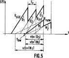
本発明の原理は、トランジションにて新規シーケンスのビットレートを局所的に増やして、vbv(N1)を、vbv(03)にせいぜい等しいか、又はそれよりもずっと低い値(この値をこの場合には(vbv’(N1)によって示す)にまで減らすことにある。この状態は図5に相当し、この図は、N1及び03のvbv遅延を(図4と比較して)この際如何にして、N1に関連するビットレートの変換後にコンパチブルにさせるかを示している。ピクチャN1によりピクチャ03を置換した後のグローバルなデコーダのバッファの進展を図6に示してあり、この図は本発明の原理により切り替えを行う場合に得られるストリームを示している。
式(2)から、
Rnew=新規ビデオシーケンスのビットレート
Rint=本発明による方法を実施する場合の中間ビットレート
とすると、次式の関係を推論することができる。即ち、
Rint=(vbv(N1)・Rnew)/vbv(03) (5)
図5から明らかなように、中間ビットレートRintは切り替えが要求されるや否や、即ち新規のピクチャN1の最初のビットがデコーダのバッファに入る時点tswにストリームに供給される(Roldは旧のビデオシーケンスのビットレートを示す)。図6にて明らかなように、この時点tswにはピクチャ01はまだ復号されておらず、その最終ビットはデコーダのバッファに中間ビットレートRintで導入されることになる。このピクチャ01を復号する際に、このピクチャO2の最終ビットはデコーダのバッファに完全には導入されず、この導入もRintにて成される。ピクチャO2を復号する場合にも同様に、(03に置き換える)N1の最終ビットはデコーダのバッファにまだ完全には導入されず、この導入はまだRintにて行われる。N1を復号する際には、後続する全てのvbv遅延(N2等の)がコンパチブルになり、後続ピクチャ(N2等)を導入するためのビットレートは、この際新規のビデオシーケンスのビットレートRnewになる。
本発明は上述した実施例のみに限定されるものでなく、発明の範疇を逸脱することなく変更を加え得ることは明らかである。例えば、中間ビットレートRintが旧のビットレートRoldよりも高くなる場合には、トランジションにてオーバフローが出現しないように注意しなければならない。
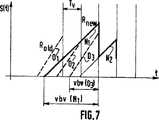
第2として、N1のビットレートは必ずしも常に漠然と或る適当なvbv遅延値に達するまで増やすことはできない。即ち、一般にビデオシーケンスは他のエレメンタリーストリームと多重して、多重トランスポートストリームを形成するが、この場合にビットレートを局所的に変更する方法は、前記多重トランスポートストリームに使用できる帯域幅によって制限される。図7及び図8は、切り替え問題(vbv(N1)がvbv(03)よりも大きい場合に、切り替え操作を行うことができない)及び前述したような切り替え方法の実施をそれぞれ示したものであり、vbv(N1)は新規シーケンスの最初に伝送されるピクチャN1のビットレートを増やすことによって減少している。使用可能な帯域幅が制限されている場合に、N1のビットレートを増やすことは、vbv(N1)の値をvbv(03)に匹敵する値にするのには十分でない。図面の簡単化のために、ここでは旧のシーケンスのビットレートRoldを(ピクチャN1に対する)Rnewの増加に対する帯域制限に相当するものとする。図8に示したように、N1のビットレートが03に対応するビットレートに等しい値にまで増大した後の値vbv(N1)は、実際には(この図面では)まだvbv(03)よりも大きい(次の図9及び図11における二重の線は前記ピクチャN1のビットレートの変更前のピクチャN1に対応するものである)。
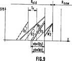
図9から明らかなように、本発明に従って、新規シーケンスの後続ピクチャN2に対するビットレート増やすようにする場合には、デコーダのバッファが部分的に空になり、vbv(N1)が再度低下するが、今度は、この低下量はN1及び03のvbv遅延をコンパチブルにするのに十分である。さらに一般的には、必要ならば(即ち、前記量がN1及び03のvbv遅延をコンパチブルにするのに十分でない場合には)、ビットレートを第1番目、次いで第2番目の新規ピクチャで増やすだけでなく、後続する各ピクチャでも、前記vbv遅延のコンパチビリティを得るのに十分な程度にまで順次増やすことを提案することができる。
前記一般論はもっと正確に調べることができ、斯様な汎用ビットレートの変更後のバッファの新規の状態及びvbv遅延についての算定数値を提案することができる。
この研究に対しては次のようなことを仮定する。即ち、
(a)指標“b”を有する変数の表記法はいずれもビットレートの変更前の変数を示す;
(b)指標“a”を有する変数の表記法はいずれもビットレートの変更後の変数を示す;
(c)本発明の実施は旧のストリームのピクチャに無関係な新規のストリームに関連するだけであるから、新規のシーケンスの或る画像Nkを考慮する表記法はいずれもこの画像の指標kに要約する;
(d)復号時間td(k)及びピクチャサイズd(k)は処理中は変更されない。
まだ説明してない使用する他の表記法は次の通りである。
-ts(I)=ピクチャIの最初のビットがデコーダバッファに入る時間;
-tsa(1),...,tsa(I),...,tsa(n)=ts(I)と同様な時間であるも、ビットレートの変更後で、新規シーケンスのピクチャ1,...,i,...,nに対する時間;
-d(1),...,d(i),....d(n)=ピクチャ1,...,i,...,nのビットサイズ。
ビットレートの変更はピクチャn(nの値をどの程度にしなければならないかについては後に説明する)を復号するまで行うものとする。従って、tsa(1)〜td(n)の間の時間tの間はビットレートがRoldに等しくなり、td(n)よりも高い時間tの間は、ビットレートがRnewに等しくなる。td(n)後にはバッファの充満度は変わらず、k>nに対して、S-a(k)=S-b(k)及びS+a(k)=S+b(k)となる。時間td-(n)におけるバッファ状態はS-b(n)である。この場合、時間t-d(n-1)における新たなバッファ状態は次のように推論することができる。
S-a(n-1)=S-b(n)−Rold・Tv+d(n-1) (6)
さらに、
S-b(n-1)=S-b(n)−Rnew・Tv+d(n-1) (7)
従って、次式を推論することができる。
S-a(n-1)=S-b(n-1)−(Rold-Rnew)・Tv (8)
同様に、次のように表わすことができる。
S-a(n-2)=S-b(n-2)−(Rold−Rnew)・2Tv (9)
そして、帰納的には、[0,...,n-1]におけるkに対しては、次のようになる。
S-a(n-k)=S-b(n-k)−(Rold-Rnew)・kTv (10)
同様に、[0,...,n-1]におけるkに対して次のように表わすことができる。
S+a(n-k)=S+b(n-k)−(Rold-Rnew)・kTv (11)
新規のvbv遅延も[0,...,n-1]におけるkに対して、次のように計算することができる。
vbva(n-k)=S-a(n-k)/Rold (12)
式(10)から、i=[0,...,n-1]におけるkに対して、次式を推論することができる。
vbva(n-k)=(S-b(n-k)/Rnew)・(Rnew/Rold)−kTv・(1-Rnew/Rold) (13)
従って、[0,...,n-1]におけるkに対しては次のようになる。
vbva(n-k)=vbvb(n-k)/Rnew)・(Rnew/Rold)−kTv・(1-Rnew/Rold) (14)
なお、式(10)及び(11)から、RoldはRnewよりも高くなるから、局所ビットレートの増加後には、本来のバッファの充満度が低くなることに留意しなければならない。従って、このようなことを留意しないと、アンダーフローが生じることになる。アンダーフローを生じなくする条件によって、nの値をどの程度にし得るかが決定される。
局所ビットレートの増大後のバッファの充満度を迎合的なものとするには、k=[0,...,n-1]に対して次のような条件を満足させるようにしなければならない。即ち、
S+a(n-k)>0 (15)
これは式(11)から[0,...,n-1]におけるkに対して、次のようになる。
S+b(n-k)>kTv・(Rold-Rnew)・kTv (16)
Vbv遅延に対する条件も式であらわすことができ、[0,...,n-1]におけるkに対して次のような場合に、バッファはアンダーフローを生じなくなる。即ち、
Vbvb(n)>Tv (17)
これは式(14)から、[0,...,n-1]におけるkに対して次のようになる。
vbva(n-k)>Tv・(Rold-Rnew+k(Rold/Rnew−1) (18)
アンダーフローの問題がない場合には、vbv遅延は最小可能遅延値d(1)/Roldに達することになる。
図10〜図12はn=2の場合にアンダーフローが生じる場合の例を示し、図10は最初のストリームを表わし、図11はピクチャN1を復号するまでのビットレートの増加を示し、図12はピクチャN2を復号するまでのビットレートの増加を示す(前述したように、二重の線は、ピクチャN1,N2のビットレートの変更前のこれらのピクチャN1,N2に相当する。この最後の場合には、アンダフローが生じるも、N1を復号するまでしかビットレートが増大しない場合には、アンダーフローは生じない。このことが結局はアンダーフローを生じさせない条件であり、これによりビットレートを何ら問題なく増加させることができる新規シーケンスのピクチャ数が決定されることになる。
しかしながら、本発明による方法によってvbv遅延を低減させたの後に、vbv遅延がまだコンパチブルにならない状態のままであることが時々ある。このような場合には、前記方法を、1997年5月27日に出願した欧州特許出願第9741160.3(PHF997557)に記載されているような、所謂最小ピクチャの挿入に基づく第2の方法と組み合わせることができる。前記文献による方法はビットレートを最早変更せず、その代わりに、新規のビデオシーケンスをk個の或る所定数のピクチャによって遅延させ、且つk個の最小ピクチャ、即ち、できるだけ低いビット数で符号化され、しかも復号処理に迎合的なピクチャを旧と新のシーケンス間の復旧スペース内に挿入する。図13及び図14は上述したようにビットレートを局所的に変更させる装置及び前述した2つの方法を組み合わせて行う装置にてそれぞれ実行させる主要なステップを線図的に示したものである。図14におけるR(of_min)はオーバフローを起こさない最小のビットレートを示す。
【図面の簡単な説明】
図1は異なるタイプの符号化ピクチャを含むGOPの例を示し;
図2は、一定のビットレートで符号化し、且つピクチャを規則的な時刻に瞬時的に復号するストリームに対するデコーダバッファの時間に対する充満度の例を示し;
図3は図2のデコーダバッファの充満度の表現を用いるとピクチャIjの主要な有効パラメータを識別できることを示し;
図4は旧のシーケンスと新のシーケンスとの切り替えを行うことができない状態を示し;
図5は本発明による方法の原理を示し;
図6は前記原理に従って切り替えを行う場合に得られるストリームを示し;
図7及び図8は本発明による方法の制限、即ち図7では観測できない切り替え問題を図8に示すような本発明の実施によっては完全には解決されないことを示し;
図9は前記制限を解決すべく本発明を改善した方法の原理を示し;
図10〜図12は、アンダーフローが生じる状態を示し;
図13及び図14は、上述した方法を実施するための切替え装置及びこの装置の他の例にて行われるそれぞれのステップを示す。The present invention relates to a video decoder comprising a buffer for receiving a picture to be decoded, before the picture is decoded, the bit rate beingdecremented from the first coded picture sequence having a bit rate of Rold . It relates to a method for switching to a lower Rnew second coded picture sequence and a corresponding device for implementing this switching method.
BACKGROUND OF THE INVENTION As described in the document “MPEG video coding: a basic tutorial introduction”, BBC report RD 1996/3, MPEG-type compressed video sequences are subdivided into groups of pictures (or GOPs). The group itself includes various types of coded pictures (GOP examples will be described with reference to FIG. 1) as follows. That is,
An intra-coded picture (I-picture) that is coded without reference to other screens;
A predictive coded picture (P-picture) that is coded using predictions that refer to past screens;
-Bidirectional predictive coded pictures (B-pictures) that are encoded using predictions that refer to past and / or future screens (arrows indicate respective reference screens for each P-picture or B-picture).
Due to various types of prediction, each picture is encoded more or less effectively, and the resulting number of bits is not constant. Furthermore, according to the MPEG specification, a picture should be instantaneously decoded for each picture period Tv , so thefirst bit of the encoded picture does not spend the same time in the decoder buffer. This variable time defined by MPEG syntax is called vbv delay (vbv = video buffering verifier). An example of decoder buffer fullness for a stream that is encoded at a constant bit rate and that instantly decodes a picture every picture period Tv is shown as vbv (I0 ), vbv ( I1 ),. . . , Vbv (I4 ),. . . FIG. 2 shows the consecutive pictures I0 to I4 (decoder buffer fullness S (t) with respect to time t). The bit rate for a picture is given by the slope, and the fullness (or decoder buffer state) is given by the highest point for each period Tv.
According to FIG. 3, the size d (Ij) of this picture Ij decoded at time td (Ij) when a picture Ij is moved from the decoder buffer is:
d (Ij) = S - ( Ij) -S + (Ij) (1)
Where S− (Ij) and S+ (Ij) are time td− (Ij) (= time just before moving picture Ij from the decoder buffer) and time td+ (Ij) (= picture The buffer state of the decoder at the time immediately after Ij is moved from the decoder buffer is shown. The picture Ij hand, and its vbv delay vbv (Ij), the bit rate R of the video stream, buffer status of the decoder S- relationship between (Ij) is given by the following equation. That is,
S - (Ij) = vbv ( Ij) · R (2)
Further, the following equation is also established. That is,
S+(Ij) = S−(Ij + 1) −R · Tv (3)
From the relationships of equations (2), (1), and (3) above, a more accurate relationship can be deduced (in bits) that provides the size d (Ij) of the decoded picture Ij. That is,
d (Ij) = R ・ (vbv (Ij) -vbv (Ij + 1) + Tv) (4)
According to this moderation model, simple switching between two compressed (encoded) video sequences is not always possible. That is, switching between the pictures to be decoded in each cycle Tv is, vbv delayof the new picture to be transmittedfirst is, can not be carried out is greater than vbv delay thefirst of the replacedthat old picture. This state is shown in FIG. 4, in which the vbv delay vbv (N1) of picture N1 of the new sequence is greater than the vbv delay vbv (03 ) of
It is known in the MPEG-2 standard (eg as described in European
SUMMARY OF THE INVENTION It is an object of the present invention to provide a method that can switch video sequences without forcing splicing point generation.
To this end, the present invention provides a method as described at theoutset , wherein thefirst bit of thefirsttransmitted picture (N1 ) of the secondencoded picture sequence decodes thefirst transmitted picture. The period vbv (N1 ) that must be spent in the decoder buffer before time is before thefirst bit of the picture (03 ) to be replaced at the beginning of the firstcoded picture sequence is decoded. The bit rate ofthefirst transmittedpicture of the secondencoded picture sequence is greater than theperiod vbv (N1) if it is greater than a similar period vbv (03 ) that must be spent in the buffer.There whereinthe Ru isat least increased to a value Rintto be reduced to it corresponds to at most a value equal tothe period vbv (03).
In this case, switching can be performed without a splicing point. According to the present invention, andthe beginning of the replacedthat old picture, a respective vbv delay of the new pictureinitiallyRu is transmitted compatible, thus to avoid longer necessary splicing point to perform the switching operation Increase the bit rate locally.
However, the bit rate cannot always be increased vaguely until some suitable vbv delay value is reached. For example, a video sequence can be multiplexed with other elementary streams to form a multiple transport stream, in which case the above-described method is limited by the bandwidth available in the multiple transport stream. The
According to the invention, in order to improve the method described above, when the bit rate bandwidth is limited:
(A) The bit rate of the picture N1to be transmitted first is set to the following two values, that is, the maximum bit rate value corresponding to the limited bandwidth,and the period vbv (N1 ) is set to the period vbv. Increase to the lower of the values Rint to be reduced correspondingly to (03 ) at most equal values;
(B) The operation of (a) is repeated for thenextpicture of the secondencoded picture sequence only when the lower value is the value of the maximum bit rate corresponding to the limited bandwidth;
Only when the value of the lower at the end of the operation of (c) is to a value of said maximum bit rate, subsequent pictures N3 of the operation: (a) the secondcoded picture sequence, N4,. . . Repeat in the same way.
If there is bandwidth limitations with respect to the increase in bit rate, the despite it is constrained by bandwidthlimitations, continuous bit rate required as many pictures of the secondcoded picture sequence To improve the method described above byreducing the vbv delay of the first picture as much as possible .
The features and advantages of the present invention will be made clear with reference to the accompanying drawings.
The principle of the present invention is to increase the bit rate of the new sequence locally at the transition so that vbv (N1 ) is at most equal to or much lower than vbv (03 ). The case is to reduce to (indicated by vbv ′ (N1 )), which corresponds to FIG. 5, which shows the vbv delay of N1 and 03 (compared to FIG. 4). At this time in the how, it shows the evolution of the buffer of the global decoder after replacing the
From equation (2)
If Rnew = bit rate of a new video sequence Rint = intermediate bit rate when implementing the method according to the invention, the relationship of the following equation can be inferred. That is,
Rint= (vbv (N1) · Rnew) / vbv (03) (5)
As is apparent from FIG. 5, the intermediate bit rate Rint is supplied to the stream as soon as switching is required, ie at the time tsw when thefirst bit of the new picture N1 enters the decoder buffer (Rold Indicates the bit rate of the old video sequence). As is apparent in FIG. 6,
The present invention is not limited to the above-described embodiments, and it is obvious that modifications can be made without departing from the scope of the invention. For example, when the intermediate bit rate Rint is higher than theold bit rate Rold , care must be taken so that no overflow occurs in the transition.
Second, the bit rate of N1 is not always vaguely increased until it reaches some suitable vbv delay value. That is, in general, a video sequence is multiplexed with other elementary streams to form a multiplexed transport stream. In this case, the method of locally changing the bit rate depends on the bandwidth available for the multiplexed transport stream. Limited. 7 and 8, the switching problem (vbv (N1) is is greater than vbv (03), it is not possible to switch operations) and alsothe respectively showing exemplary switching method as described above in and, vbv (N1) is reduced by increasingthe bit rate of the picture N1transmitted first in the new sequence. Increasing the bit rate of N1 when the available bandwidth is limited is not enough to make the value of vbv (N1 ) comparable to vbv (03 ). For simplification of the drawing, the bit rate Rold of theold sequence is assumed here to correspond to the bandwidth limitation for the increase of Rnew (for picture N1 ). As shown in FIG. 8, the value after the increase to a value equal to the bit rate the bit rate of N1 corresponds to 03 vbv (N1) is actually (in this drawing) yet vbv (03) greater than (following double lines in FIGS. 9 and 11 corresponds to a picture N1 before the change of the bit rate of the picture N1).
As is apparent from FIG. 9, when the bit rate for the subsequent picture N2 of the new sequence is increased according to the present invention, the decoder buffer is partially emptied and vbv (N1 ) decreases again. This time, however, this reduction is sufficient to make the N1 and 03 vbv delays compatible. More generally, if necessary (ie if the amount is not sufficient to make the N1 and 03 vbv delays compatible), the bit rate will be the first and then the second new picture. It is possible to propose that each subsequent picture is sequentially increased to a level sufficient to obtain the vbv delay compatibility.
The general theory can be examined more precisely, and a numerical value for the new state of the buffer and the vbv delay after such a general bit rate change can be proposed.
The following is assumed for this study. That is,
(A) Any notation of a variable having the index “b” indicates the variable before the bit rate change;
(B) Any notation of a variable having an index “a” indicates a variable after changing the bit rate;
(C) Since the implementation of the present invention only relates to a new stream unrelated to the pictures of the old stream, any notation that takes into account a certain image Nk of the new sequence is Summarize;
(D) The decoding time td (k) and the picture size d (k) are not changed during processing.
Other notation not yet used is as follows.
-ts (I) = time when thefirst bit of picture I enters the decoder buffer;
-tsa (1),. . . , Tsa (I),. . . , Tsa (n) = ts (I), but after changing the bit rate, a new sequence of
-d (1),. . . , D (i),. . . . d (n) =
It is assumed that the bit rate is changed until picture n (how much the value of n has to be explained later) is decoded. Thus, during the time t betweent sa (1) ~t d ( n) is the bit rate becomes equal to Rold, between td (n) greater than the time t, the bit rate to Rnew Will be equal. After td (n), the buffer fullness does not change, and for k> n, S−a (k) = S−b (k) and S+a (k) = S+b (k) Become. Time td- buffer status in (n) is S- ab (n). In this case, the new buffer state at time t−d (n−1) can be inferred as follows.
S - a (n-1) = S - b (n) -R old · T v + d (n-1) (6)
further,
S - b (n-1) = S - b (n) -R new · T v + d (n-1) (7)
Therefore, the following equation can be inferred.
S−a(n−1) = S−b(n−1) − (Rold−Rnew) · Tv (8)
Similarly, it can be expressed as:
S−a(n−2) = S−b(n−2) − (Rold−Rnew) · 2Tv (9)
And inductively, [0,. . . , N−1] for k,
S−a(nk) = S−b(nk) − (Rold−Rnew) · kTv (10)
Similarly, [0,. . . , N-1] can be expressed as follows.
S + a (nk) = S + b (nk) - (R old -R new) · kT v (11)
The new vbv delay is also [0,. . . , N−1] can be calculated as follows.
vbva (nk) = S−a (nk) / Rold (12)
From equation (10), i = [0,. . . , N-1] for k in the following equation.
vbv a (nk) = (S - b (nk) / R new) · (R new / R old) -kT v · (1-R new / R old) (13)
Therefore, [0,. . . , N-1] with respect to k.
vbva(nk) = vbvb(nk) / Rnew) · (Rnew/ Rold) −kTv· (1−Rnew/ Rold) (14)
Note that from equations (10) and (11), Rold is higher than Rnew , so that after the local bit rate is increased, the original fullness of the buffer is reduced. Therefore, if this is not noted, underflow will occur. The condition for preventing underflow will determine how much the value of n can be made.
To make the buffer fullness after increasing the local bit rate compliant, k = [0,. . . , N-1] must satisfy the following conditions. That is,
S+a (nk)> 0 (15)
This is derived from equation (11) [0,. . . , N−1] with respect to k.
S + b (n-k) > kT v · (R old -R new) · kT v (16)
The condition for Vbv delay can also be expressed as an expression [0,. . . , N-1] with respect to k in the following cases, the buffer does not underflow. That is,
Vbvb (n)> Tv (17)
This is obtained from the equation (14) from [0,. . . , N−1] with respect to k.
vbv a (nk)> T v · (R old -R new + k (R old / R new -1) (18)
If there is no underflow problem, the vbv delay will reach the minimum possible delay value d (1) / Rold .
10 to 12 show an example in which underflow occurs when n = 2, FIG. 10 shows the first stream, FIG. 11 shows the increase in bit rate until picture N1 is decoded, 12 shows the increase of bit rate until the decoding of the picture N2 (as described above, double line, the picture N1, these pictures N1 before the change of the bit rate of N2, N2 In this last case, underflow occurs, but underflow does not occur if the bit rate only increases until N1 is decoded, so that it does not cause underflow in the end. This determines the number of pictures in the new sequence that can increase the bit rate without any problem.
However, after reducing the vbv delay by the method according to the present invention, sometimes the vbv delay still remains incompatible. In such a case, the method is a second method based on insertion of a so-called minimum picture as described in European Patent Application No. 9741160.3 (PHF997557) filed on May 27, 1997. Can be combined. The method according to the literature no longer changes the bit rate; instead, the new video sequence is delayed by a certain number of pictures of k and coded with the smallest number of k pictures, ie the lowest possible number of bits. And a picture that is compliant with the decoding process is inserted into the recovery space between the old and new sequences. FIG. 13 and FIG. 14 diagrammatically show the main steps executed by the apparatus for locally changing the bit rate as described above and the apparatus for combining the two methods described above. R (of_min) in FIG. 14 indicates the minimum bit rate that does not cause overflow.
[Brief description of the drawings]
FIG. 1 shows an example of a GOP containing different types of coded pictures;
FIG. 2 shows an example of the degree of fullness of the decoder buffer for a stream that encodes at a constant bit rate and instantly decodes a picture at a regular time;
FIG. 3 shows that using the decoder buffer fullness representation of FIG. 2 can identify the main effective parameters of picture Ij;
FIG. 4 shows a state in which switching between the old sequence and the new sequence cannot be performed;
FIG. 5 shows the principle of the method according to the invention;
FIG. 6 shows the stream obtained when switching according to the principle;
FIGS. 7 and 8 show that the limitation of the method according to the invention, i.e. the switching problem not observable in FIG. 7, is not completely solved by the implementation of the invention as shown in FIG.
FIG. 9 shows the principle of the improved method of the present invention to solve the above limitation;
Figures 10 to 12 show the situation where underflow occurs;
13 and 14 show the respective steps performed in the switching device for carrying out the method described above and in another example of this device.
Claims (5)
Translated fromJapanese前記第2符号化ピクチャシーケンスの最初に伝送されるピクチャ(N1)の最初のビットが前記最初に伝送されるピクチャを復号する時刻の前にデコーダのバッファにて費やさなければならない期間vbv(N1)が、前記第1符号化ピクチャシーケンスの最初に置換するピクチャ(03)の最初のビットが該ピクチャそのものを復号する前に前記バッファにて費やさなければならない同様な期間vbv(03)よりも大きい場合に、
前記第2符号化ピクチャシーケンスの前記最初に伝送されるピクチャのビットレートを、前記期間vbv(N1)が前記期間vbv(03)にせいぜい等しい値にまでそれ相当に低減されるようにする値Rintにまで少なくとも増大させることを特徴とする符号化画像シーケンスの切り替え方法。In a video decoder comprising a buffer for receiving a picture to be decoded, before decoding, a second code of Rnew with a lower bit rate from a first encoded picture sequence with a bit rate of Rold In a method for switching to a categorized picture sequence,
It said period of timethe first bitmust spend at the decoder buffer before the time of decoding a pictureto be transmitted first to the second pictureto be transmitted firstcoded picture sequence (N1) vbv (N1 ) is a similar period vbv (03 ) that thefirst bit of thefirst replacement picture (03 ) of thefirstencoded picture sequence must be spent in the buffer before decoding the picture itself Larger than
The bit rate ofthefirst transmittedpicture of the secondcoded picture sequenceis reduced substantially to a value where theperiod vbv (N1) isat most equal to theperiod vbv (03). switching method for coding an image sequence, characterized inthat Ru isat least increased to a value Rint.
(a)前記最初に伝送されるピクチャN1のビットレートを、次の2つの値、即ち、前記制限帯域幅に対応する最大ビットレートの値と、前記期間vbv(N1)を前記期間vbv(03)にせいぜい等しい値にまで対応して低減させる値Rintのうちの低い方の値にまで増大させ、
(b)前記低い方の値が前記制限帯域幅に相当する最大ビットレートの値となる場合にのみ、前記(a)の動作を前記第2符号化ピクチャシーケンスの次のピクチャに対して繰り返し、
(c)前記低い方の値が前記最大ビットレートの値である場合にのみ,前記動作(a)を第2符号化ピクチャシーケンスの後続ピクチャN3,N4...に対して同様に繰り返すことを特徴とする請求項1に記載の方法。If the bit rate bandwidth is limited,
(A) The bit rate of the picture N1to be transmitted first is set to the following two values, that is, the maximum bit rate value corresponding to the limited bandwidth,and the period vbv (N1 ) is set to the period vbv. (03) to increase to a value of the lower of correspondingly reduced to a value Rint until at most equal,
(B) The operation of (a) is repeated for thenextpicture of the secondencoded picture sequence only when the lower value is the value of the maximum bit rate corresponding to the limited bandwidth,
Only when the value of the direction (c)before SL low a value of the maximum bit rate, subsequent pictures N3 of the operation: (a) the secondcoded picture sequence, N4. . . The method of claim 1, wherein the method is repeated in the same manner.
Rint=(vbv(N1)・Rnew)/vbv(03)
によって表わされることを特徴とする請求項2に記載の方法。The maximum bit rate value Rint is equal to the bit rate Rold and the value Rint is:
Rint= (vbv (N1) · Rnew) / vbv (03)
The method of claim2 , wherein the method is represented by:
復号すべきピクチャを受信するためのバッファを具えているビデオデコーダであって、復号する前に、ビットレートがRoldの第1符号化ピクチャシーケンスからビットレートがそれよりも低いRnewの第2符号化ピクチャシーケンスに切り替えを行うように構成したビデオデコーダを備える装置において、
前記第2符号化ピクチャシーケンスの最初に伝送されるピクチャ(N1)の最初のビットが前記最初に伝送されるピクチャを復号する時刻の前にデコーダのバッファにて費やさなければならない期間vbv(N1)が、前記第1符号化ピクチャシーケンスの最初に置換するピクチャ(03)の最初のビットが該ピクチャそのものを復号する前に前記バッファにて費やさなければならない同様な期間vbv(03)よりも大きい場合に、
前記第2符号化ピクチャシーケンスの前記最初に伝送されるピクチャのビットレートを、前記期間vbv(N1)が前記期間vbv(03)にせいぜい等しい値にまでそれ相当に低減されるようにする値Rintにまで少なくとも増大させることを特徴とする装置。An apparatus for performing switching by the method according to claim 1,
A video decoder comprising a buffer for receiving a picture to be decoded, before decoding, from afirst encoded picture sequencehaving a bit rate of Rold anda second of Rnew havingalower bit rateIn an apparatus comprising a video decoder configured to switch to an encoded picture sequence,
Theperiod vbv (N) in which the first bit of the firsttransmitted picture (N1) ofthe second coded picture sequencemust be spent in the decoder buffer before the time of decoding the first transmitted picture1) is asimilar period vbv (03) thatthe first bit of the firstreplacement picture (03) of the firstencoded picture sequencemust be spent in the buffer before decoding the picture itselfLarger than
The bit rate of the first transmitted picture of the second coded picture sequenceis reduced substantially to a value where theperiod vbv (N1) isat most equal to theperiod vbv (03).An apparatus characterized by increasing at least to thevalue Rint .
Applications Claiming Priority (5)
| Application Number | Priority Date | Filing Date | Title |
|---|---|---|---|
| EP98400223 | 1998-02-03 | ||
| EP98400223.8 | 1998-02-03 | ||
| EP98401929.9 | 1998-07-28 | ||
| EP98401929 | 1998-07-28 | ||
| PCT/IB1999/000163WO1999040728A1 (en) | 1998-02-03 | 1999-01-28 | Method of switching of coded video sequences and corresponding device |
Publications (2)
| Publication Number | Publication Date |
|---|---|
| JP2001519992A JP2001519992A (en) | 2001-10-23 |
| JP4275746B2true JP4275746B2 (en) | 2009-06-10 |
Family
ID=26151561
Family Applications (1)
| Application Number | Title | Priority Date | Filing Date |
|---|---|---|---|
| JP54018599AExpired - Fee RelatedJP4275746B2 (en) | 1998-02-03 | 1999-01-28 | Coded video sequence switching method and apparatus corresponding thereto |
Country Status (6)
| Country | Link |
|---|---|
| US (1) | US6351564B1 (en) |
| EP (1) | EP1004207A1 (en) |
| JP (1) | JP4275746B2 (en) |
| KR (1) | KR100664452B1 (en) |
| CN (1) | CN1169373C (en) |
| WO (1) | WO1999040728A1 (en) |
Families Citing this family (28)
| Publication number | Priority date | Publication date | Assignee | Title |
|---|---|---|---|---|
| GB2353653B (en)* | 1999-08-26 | 2003-12-31 | Sony Uk Ltd | Signal processor |
| JP2001285868A (en)* | 2000-03-29 | 2001-10-12 | Victor Co Of Japan Ltd | Device and method for changing-over animation code string |
| US7050460B1 (en)* | 2000-04-14 | 2006-05-23 | Ati International Srl | Method and apparatus for multiplexing data streams using time constraints |
| FR2841160B1 (en)* | 2002-06-19 | 2004-07-23 | Solystic | METHOD FOR PROCESSING POSTAL ITEMS USING VOICE SYNTHESIS |
| US9591339B1 (en) | 2012-11-27 | 2017-03-07 | Apple Inc. | Agnostic media delivery system |
| US9774917B1 (en) | 2012-12-10 | 2017-09-26 | Apple Inc. | Channel bar user interface |
| US10200761B1 (en) | 2012-12-13 | 2019-02-05 | Apple Inc. | TV side bar user interface |
| US9532111B1 (en) | 2012-12-18 | 2016-12-27 | Apple Inc. | Devices and method for providing remote control hints on a display |
| US10521188B1 (en) | 2012-12-31 | 2019-12-31 | Apple Inc. | Multi-user TV user interface |
| US12149779B2 (en) | 2013-03-15 | 2024-11-19 | Apple Inc. | Advertisement user interface |
| CN111782130B (en) | 2014-06-24 | 2024-03-29 | 苹果公司 | Column interface for navigating in a user interface |
| KR102398394B1 (en) | 2014-06-24 | 2022-05-16 | 애플 인크. | Input device and user interface interactions |
| KR101973045B1 (en)* | 2014-09-24 | 2019-04-26 | 애플 인크. | Management of the channel bar |
| DK201670581A1 (en) | 2016-06-12 | 2018-01-08 | Apple Inc | Device-level authorization for viewing content |
| DK201670582A1 (en) | 2016-06-12 | 2018-01-02 | Apple Inc | Identifying applications on which content is available |
| US11966560B2 (en) | 2016-10-26 | 2024-04-23 | Apple Inc. | User interfaces for browsing content from multiple content applications on an electronic device |
| US12307082B2 (en) | 2018-02-21 | 2025-05-20 | Apple Inc. | Scrollable set of content items with locking feature |
| AU2019100574B4 (en) | 2018-06-03 | 2020-02-20 | Apple Inc. | Setup procedures for an electronic device |
| US11683565B2 (en) | 2019-03-24 | 2023-06-20 | Apple Inc. | User interfaces for interacting with channels that provide content that plays in a media browsing application |
| EP3928194A1 (en) | 2019-03-24 | 2021-12-29 | Apple Inc. | User interfaces including selectable representations of content items |
| EP3928526A1 (en) | 2019-03-24 | 2021-12-29 | Apple Inc. | User interfaces for viewing and accessing content on an electronic device |
| CN113906419A (en) | 2019-03-24 | 2022-01-07 | 苹果公司 | User interface for media browsing application |
| CN113906380A (en) | 2019-05-31 | 2022-01-07 | 苹果公司 | User interface for podcast browsing and playback applications |
| US11863837B2 (en) | 2019-05-31 | 2024-01-02 | Apple Inc. | Notification of augmented reality content on an electronic device |
| US11843838B2 (en) | 2020-03-24 | 2023-12-12 | Apple Inc. | User interfaces for accessing episodes of a content series |
| US11899895B2 (en) | 2020-06-21 | 2024-02-13 | Apple Inc. | User interfaces for setting up an electronic device |
| US11720229B2 (en) | 2020-12-07 | 2023-08-08 | Apple Inc. | User interfaces for browsing and presenting content |
| US11934640B2 (en) | 2021-01-29 | 2024-03-19 | Apple Inc. | User interfaces for record labels |
Family Cites Families (14)
| Publication number | Priority date | Publication date | Assignee | Title |
|---|---|---|---|---|
| JPS5841435B2 (en) | 1981-04-10 | 1983-09-12 | 新日本製鐵株式会社 | How to control the suction head |
| US5534944A (en)* | 1994-07-15 | 1996-07-09 | Matsushita Electric Corporation Of America | Method of splicing MPEG encoded video |
| EP0692911B1 (en)* | 1994-07-15 | 2000-03-08 | Matsushita Electric Industrial Co., Ltd. | Method of splicing MPEG encoded video |
| CA2157066C (en)* | 1994-10-21 | 1999-09-21 | Nelson Botsford Iii | Method for controlling a compressed data buffer |
| US5687095A (en)* | 1994-11-01 | 1997-11-11 | Lucent Technologies Inc. | Video transmission rate matching for multimedia communication systems |
| US5913031A (en)* | 1994-12-02 | 1999-06-15 | U.S. Philips Corporation | Encoder system level buffer management |
| JPH09512410A (en)* | 1995-02-15 | 1997-12-09 | フィリップス エレクトロニクス ネムローゼ フェンノートシャップ | Video signal transcoding method and apparatus |
| GB2307613B (en)* | 1995-08-31 | 2000-03-22 | British Broadcasting Corp | Switching bit-rate reduced signals |
| US6011598A (en)* | 1996-03-28 | 2000-01-04 | Sanyo Electric Co., Ltd. | Decoding start controller, decoder, and decoding system |
| EP0805601B1 (en)* | 1996-05-02 | 2005-03-30 | Sony Corporation | Encoding, storing and transmitting digital signals |
| CA2208950A1 (en)* | 1996-07-03 | 1998-01-03 | Xuemin Chen | Rate control for stereoscopic digital video encoding |
| US6188700B1 (en)* | 1996-11-07 | 2001-02-13 | Sony Corporation | Method and apparatus for encoding MPEG signals using variable rate encoding and dynamically varying transmission buffers |
| JP3555729B2 (en)* | 1997-04-22 | 2004-08-18 | 日本ビクター株式会社 | Method and apparatus for processing variable-length encoded data |
| JP2000515711A (en) | 1997-05-27 | 2000-11-21 | コーニンクレッカ フィリップス エレクトロニクス エヌ ヴィ | Video sequence switching method, switching device thereof, and decoding system |
- 1999
- 1999-01-28JPJP54018599Apatent/JP4275746B2/ennot_activeExpired - Fee Related
- 1999-01-28CNCNB998004456Apatent/CN1169373C/ennot_activeExpired - Fee Related
- 1999-01-28EPEP99900608Apatent/EP1004207A1/ennot_activeWithdrawn
- 1999-01-28KRKR1019997009016Apatent/KR100664452B1/ennot_activeExpired - Fee Related
- 1999-01-28WOPCT/IB1999/000163patent/WO1999040728A1/ennot_activeApplication Discontinuation
- 1999-02-02USUS09/244,841patent/US6351564B1/ennot_activeExpired - Lifetime
Also Published As
| Publication number | Publication date |
|---|---|
| EP1004207A1 (en) | 2000-05-31 |
| WO1999040728A1 (en) | 1999-08-12 |
| KR100664452B1 (en) | 2007-01-04 |
| US6351564B1 (en) | 2002-02-26 |
| CN1169373C (en) | 2004-09-29 |
| CN1262846A (en) | 2000-08-09 |
| JP2001519992A (en) | 2001-10-23 |
| KR20010005939A (en) | 2001-01-15 |
Similar Documents
| Publication | Publication Date | Title |
|---|---|---|
| JP4275746B2 (en) | Coded video sequence switching method and apparatus corresponding thereto | |
| JP4223567B2 (en) | Coded video sequence switching method and apparatus | |
| US6034731A (en) | MPEG frame processing method and apparatus | |
| US6587506B1 (en) | Video editing apparatus, video editing method, and data storage medium for a video editing program | |
| KR100538135B1 (en) | Method and apparatus for information stream frame synchronization | |
| EP0982948B1 (en) | MPEG stream switching process for open GOPs | |
| US8260122B2 (en) | MPEG picture data recording apparatus, MPEG picture data recording method, MPEG picture data recording medium, MPEG picture data generating apparatus, MPEG picture data reproducing apparatus, and MPEG picture data reproducing method | |
| JP4676331B2 (en) | Code conversion method and apparatus | |
| KR20070084128A (en) | Two-stage arithmetic decoding to convert to intermediate format | |
| US7333711B2 (en) | Data distribution apparatus and method, and data distribution system | |
| US6618438B1 (en) | MPEG stream switching process | |
| US7342961B2 (en) | Encoded data outputting apparatus and method | |
| KR20050020710A (en) | Coding device and coding method | |
| US7586426B2 (en) | Image coding apparatus and method thereof | |
| US20100274918A1 (en) | Stream data multiplexing device and multiplexing method | |
| JPWO2008053557A1 (en) | Moving image re-encoding device, moving image re-encoding method, moving image re-encoding program, and recording medium storing moving image re-encoding program | |
| KR20020000810A (en) | Variable bit rate video encoding method and device | |
| JPH1174799A (en) | Processing method of variable length encoding data and buffer controller | |
| JP3341839B2 (en) | Image signal encoding buffer management device | |
| JP2009100303A (en) | Moving image encoding device and data processing method therefor | |
| JPH09139916A (en) | Picture data encoding device | |
| JP2002176646A (en) | Buffer management method | |
| JP2001128169A (en) | Moving picture coding method and moving picture coding apparatus |
Legal Events
| Date | Code | Title | Description |
|---|---|---|---|
| A621 | Written request for application examination | Free format text:JAPANESE INTERMEDIATE CODE: A621 Effective date:20060125 | |
| A131 | Notification of reasons for refusal | Free format text:JAPANESE INTERMEDIATE CODE: A131 Effective date:20080624 | |
| A601 | Written request for extension of time | Free format text:JAPANESE INTERMEDIATE CODE: A601 Effective date:20080910 | |
| A602 | Written permission of extension of time | Free format text:JAPANESE INTERMEDIATE CODE: A602 Effective date:20081020 | |
| A521 | Request for written amendment filed | Free format text:JAPANESE INTERMEDIATE CODE: A523 Effective date:20081222 | |
| TRDD | Decision of grant or rejection written | ||
| A01 | Written decision to grant a patent or to grant a registration (utility model) | Free format text:JAPANESE INTERMEDIATE CODE: A01 Effective date:20090210 | |
| A01 | Written decision to grant a patent or to grant a registration (utility model) | Free format text:JAPANESE INTERMEDIATE CODE: A01 | |
| A61 | First payment of annual fees (during grant procedure) | Free format text:JAPANESE INTERMEDIATE CODE: A61 Effective date:20090305 | |
| R150 | Certificate of patent or registration of utility model | Free format text:JAPANESE INTERMEDIATE CODE: R150 | |
| FPAY | Renewal fee payment (event date is renewal date of database) | Free format text:PAYMENT UNTIL: 20120313 Year of fee payment:3 | |
| FPAY | Renewal fee payment (event date is renewal date of database) | Free format text:PAYMENT UNTIL: 20120313 Year of fee payment:3 | |
| S111 | Request for change of ownership or part of ownership | Free format text:JAPANESE INTERMEDIATE CODE: R313113 | |
| R360 | Written notification for declining of transfer of rights | Free format text:JAPANESE INTERMEDIATE CODE: R360 | |
| FPAY | Renewal fee payment (event date is renewal date of database) | Free format text:PAYMENT UNTIL: 20120313 Year of fee payment:3 | |
| FPAY | Renewal fee payment (event date is renewal date of database) | Free format text:PAYMENT UNTIL: 20120313 Year of fee payment:3 | |
| R370 | Written measure of declining of transfer procedure | Free format text:JAPANESE INTERMEDIATE CODE: R370 | |
| FPAY | Renewal fee payment (event date is renewal date of database) | Free format text:PAYMENT UNTIL: 20120313 Year of fee payment:3 | |
| S111 | Request for change of ownership or part of ownership | Free format text:JAPANESE INTERMEDIATE CODE: R313113 | |
| FPAY | Renewal fee payment (event date is renewal date of database) | Free format text:PAYMENT UNTIL: 20130313 Year of fee payment:4 | |
| R360 | Written notification for declining of transfer of rights | Free format text:JAPANESE INTERMEDIATE CODE: R360 | |
| FPAY | Renewal fee payment (event date is renewal date of database) | Free format text:PAYMENT UNTIL: 20130313 Year of fee payment:4 | |
| R350 | Written notification of registration of transfer | Free format text:JAPANESE INTERMEDIATE CODE: R350 | |
| FPAY | Renewal fee payment (event date is renewal date of database) | Free format text:PAYMENT UNTIL: 20130313 Year of fee payment:4 | |
| S111 | Request for change of ownership or part of ownership | Free format text:JAPANESE INTERMEDIATE CODE: R313113 | |
| FPAY | Renewal fee payment (event date is renewal date of database) | Free format text:PAYMENT UNTIL: 20130313 Year of fee payment:4 | |
| R350 | Written notification of registration of transfer | Free format text:JAPANESE INTERMEDIATE CODE: R350 | |
| FPAY | Renewal fee payment (event date is renewal date of database) | Free format text:PAYMENT UNTIL: 20130313 Year of fee payment:4 | |
| FPAY | Renewal fee payment (event date is renewal date of database) | Free format text:PAYMENT UNTIL: 20140313 Year of fee payment:5 | |
| R250 | Receipt of annual fees | Free format text:JAPANESE INTERMEDIATE CODE: R250 | |
| R250 | Receipt of annual fees | Free format text:JAPANESE INTERMEDIATE CODE: R250 | |
| R250 | Receipt of annual fees | Free format text:JAPANESE INTERMEDIATE CODE: R250 | |
| LAPS | Cancellation because of no payment of annual fees |