JP4275466B2 - Oxygen concentrator - Google Patents
Oxygen concentratorDownload PDFInfo
- Publication number
- JP4275466B2 JP4275466B2JP2003168911AJP2003168911AJP4275466B2JP 4275466 B2JP4275466 B2JP 4275466B2JP 2003168911 AJP2003168911 AJP 2003168911AJP 2003168911 AJP2003168911 AJP 2003168911AJP 4275466 B2JP4275466 B2JP 4275466B2
- Authority
- JP
- Japan
- Prior art keywords
- oxygen
- enriched gas
- ultrasonic
- time
- range
- Prior art date
- Legal status (The legal status is an assumption and is not a legal conclusion. Google has not performed a legal analysis and makes no representation as to the accuracy of the status listed.)
- Expired - Lifetime
Links
- 229910052760oxygenInorganic materials0.000titleclaimsdescription151
- QVGXLLKOCUKJST-UHFFFAOYSA-Natomic oxygenChemical compound[O]QVGXLLKOCUKJST-UHFFFAOYSA-N0.000titleclaimsdescription148
- 239000001301oxygenSubstances0.000titleclaimsdescription148
- 239000007789gasSubstances0.000claimsdescription112
- 238000001514detection methodMethods0.000claimsdescription35
- 230000014509gene expressionEffects0.000claimsdescription16
- 230000001902propagating effectEffects0.000claimsdescription11
- 230000005540biological transmissionEffects0.000description22
- IJGRMHOSHXDMSA-UHFFFAOYSA-NAtomic nitrogenChemical compoundN#NIJGRMHOSHXDMSA-UHFFFAOYSA-N0.000description18
- 238000000034methodMethods0.000description16
- 238000005259measurementMethods0.000description13
- XKRFYHLGVUSROY-UHFFFAOYSA-NArgonChemical compound[Ar]XKRFYHLGVUSROY-UHFFFAOYSA-N0.000description10
- 229910052757nitrogenInorganic materials0.000description9
- 229910052786argonInorganic materials0.000description5
- 238000010586diagramMethods0.000description4
- 238000006243chemical reactionMethods0.000description2
- 238000013461designMethods0.000description2
- 239000012528membraneSubstances0.000description2
- 238000012545processingMethods0.000description2
- 239000002994raw materialSubstances0.000description2
- 238000002604ultrasonographyMethods0.000description2
- 238000012935AveragingMethods0.000description1
- 230000007423decreaseEffects0.000description1
- 229940063821oxygen 21 %Drugs0.000description1
- 238000001028reflection methodMethods0.000description1
- 238000011160researchMethods0.000description1
- 230000000630rising effectEffects0.000description1
- 238000005070samplingMethods0.000description1
- 239000007784solid electrolyteSubstances0.000description1
- 238000001179sorption measurementMethods0.000description1
Images


Classifications
- G—PHYSICS
- G01—MEASURING; TESTING
- G01N—INVESTIGATING OR ANALYSING MATERIALS BY DETERMINING THEIR CHEMICAL OR PHYSICAL PROPERTIES
- G01N2291/00—Indexing codes associated with group G01N29/00
- G01N2291/02—Indexing codes associated with the analysed material
- G01N2291/028—Material parameters
- G01N2291/02809—Concentration of a compound, e.g. measured by a surface mass change
- G—PHYSICS
- G01—MEASURING; TESTING
- G01N—INVESTIGATING OR ANALYSING MATERIALS BY DETERMINING THEIR CHEMICAL OR PHYSICAL PROPERTIES
- G01N2291/00—Indexing codes associated with group G01N29/00
- G01N2291/02—Indexing codes associated with the analysed material
- G01N2291/028—Material parameters
- G01N2291/02818—Density, viscosity
- G—PHYSICS
- G01—MEASURING; TESTING
- G01N—INVESTIGATING OR ANALYSING MATERIALS BY DETERMINING THEIR CHEMICAL OR PHYSICAL PROPERTIES
- G01N2291/00—Indexing codes associated with group G01N29/00
- G01N2291/02—Indexing codes associated with the analysed material
- G01N2291/028—Material parameters
- G01N2291/02836—Flow rate, liquid level
- G—PHYSICS
- G01—MEASURING; TESTING
- G01N—INVESTIGATING OR ANALYSING MATERIALS BY DETERMINING THEIR CHEMICAL OR PHYSICAL PROPERTIES
- G01N2291/00—Indexing codes associated with group G01N29/00
- G01N2291/02—Indexing codes associated with the analysed material
- G01N2291/028—Material parameters
- G01N2291/02881—Temperature
Landscapes
- Investigating Or Analyzing Materials By The Use Of Ultrasonic Waves (AREA)
- Oxygen, Ozone, And Oxides In General (AREA)
Description
Translated fromJapanese【0001】
【発明の属する技術分野】
本発明は、超音波により、酸素濃縮ガスの酸素濃度及び流量を測定する手段を備えた酸素濃縮装置に関するものである。
【0002】
【従来の技術】
サンプルガス中を伝播する超音波の伝播速度は、サンプルガスの濃度、温度の関数として表されることが広く知られている。サンプルガスの平均分子量をM、温度をT[K]とすれば、サンプルガス中の超音波伝播速度C[m/sec]は、次式で表される。
【0003】
【数1】
ここで、k、Rは定数(k:定積モル比熱と定圧モル比熱の比、R:気体定数)である。すなわち、サンプルガス中の超音波伝播速度C[m/sec]とサンプルガスの温度T[K]が測定できれば、サンプルガスの平均分子量Mを決定できる。該サンプルガスが、例えば酸素と窒素の2分子からなるガスであれば、k = 1.4となることが知られている。該サンプルガスの平均分子量Mは、酸素の分子量を32、窒素の分子量を28として、例えば酸素100×P[%](0≦P≦1)と窒素100×(1−P)[%]の場合においては、M = 32P+28 (1−P)と記述することができ、測定された平均分子量Mから酸素濃度Pを決定できる。また、サンプルガス中の超音波伝播速度がC[m/sec]、サンプルガスの流速がV[m/sec]であったとき、サンプルガスの流れに対して順方向に超音波を送信したときに測定される超音波伝播速度V1[m/sec]は、V1= C+V、逆方向に超音波を送信したときに測定される超音波伝播速度V2[m/sec]は、V2= C−Vとなるので、サンプルガスの流速V[m/sec]は、次式2で求めることができる。
【0005】
【数2】
これにサンプルガスの流れている配管の内面積[m2]を乗じることで、サンプルガスの流量[m3/sec]を求めることができる。さらに体積換算、時間換算を行えば、流量を[L/min]で求めることも容易である。該原理を利用し、サンプルガス中を伝播する超音波の伝播速度もしくは伝播時間からサンプルガスの濃度、流量を測定する方法及び装置に関しては、種々の提案が行われている。たとえば、特開平6−213877号公報には、サンプルガスが通る配管中に超音波振動子2つを対向させて配置し、該超音波振動子間を伝播する超音波の伝播時間を計測することによってサンプルガスの濃度及び流量を測定する装置が記載されている。また、特開平7−209265号公報や特開平8−233718号公報には、超音波振動子1つを使用した音波反射方式でセンシングエリア内を伝播する超音波の伝播速度もしくは伝播時間を測定することにより、サンプルガスの濃度を測定する装置が記載されている。さらに、サンプルガスを構成する分子の数が2種類であれば、先述の通り容易にサンプルガスの濃度を特定することが可能であるが、酸素濃縮装置から出力される酸素濃縮ガスには、酸素、窒素以外に、アルゴンが含まれる。その場合の酸素濃度の特定方法は、特開2003−135601号公報や、特開2003−137510号公報に記載されている。
【0007】
【特許文献1】
特開平6−213877号公報
【特許文献2】
特開平7−209265号公報
【特許文献3】
特開平8−233718号公報
【特許文献4】
特開2003−135601号公報
【特許文献5】
特開2003−137510号公報
【特許文献6】
特開平9−318644号公報
【特許文献7】
特開昭60−138422号公報
【0008】
【発明が解決しようとする課題】
このような超音波の伝播速度を用いてサンプルガスの濃度および流量を正確に測定する方法および装置においては、超音波の伝播時間を正確に検出しなければならない。しかし、超音波の受信波形には常にノイズ成分が含まれており、超音波を受信した瞬間の時間を直接検出することは非常に困難であり、一般的に複雑な信号処理手法や、複雑なハ−ドウェアを搭載することにより、超音波伝播時間を推定する方法が用いられている。
【0009】
たとえば、特開平9−318644号公報には、受信された超音波波形を積分し、その積分出力が基準値に達したのちにおける受信波のゼロクロス時間を流速測定のための超音波伝播時間とする方法が記載されている。該方法により、受信波形の振幅が多少変動したとしてもゼロクロスのタイミングが変動しないため、受信波の到達時間に比較的近い位置でのゼロクロス時間を獲得できるが、残念ながら獲得されるゼロクロス時間は真の超音波伝播時間ではなく、とりわけ濃度測定においては真の超音波伝播時間と検出されたゼロクロス時間との差異が測定誤差に大きく影響する。
【0010】
また、特開昭60−138422号公報には、受信波形の包絡線波形から算出された近似式に基づいて包絡線波形の立ち上がり時間を検出し、真の超音波伝播時間とする方法が記載されている。しかし、包絡線波形から超音波伝播時間を推定する方法においては、包絡線波形を得るために受信波形をサンプリングするためのハ−ドウェアを必要とし、また、包絡線を計算するために複雑な信号処理を必要とするため、安価で小型の装置を作成することが困難であった。
【0011】
本発明は、複雑な信号処理やハ−ドウェアを必要とせずに酸素濃縮ガスの酸素濃度および流量を測定する方法、および、必要最小限の部品のみを用いることで安価かつ小型の超音波式ガス濃度流量測定手段を搭載した酸素濃縮装置を提供することを目的としている。
【0012】
【課題を解決するための手段】
本発明者らは、かかる目的を達成するために鋭意研究した結果、空気中から酸素を分離する酸素濃縮手段、酸素濃縮手段の下流の酸素濃縮ガスの流れる配管中に対向させて配置した超音波振動子2つ、受信超音波のゼロクロス時間検出回路を具備する酸素濃縮装置において、酸素濃縮ガスの取り得る濃度範囲、および、温度範囲から、酸素濃縮ガス中を伝播する超音波の音速の取り得る範囲を事前に知ることで好適な超音波振動子間距離を設定し、さらに、酸素濃縮ガスの取り得る流量範囲から好適な配管内半径を設定すれば、酸素濃縮ガスの温度と連続した2つ以上のゼロクロス時間のみを検出することで、受信超音波の波形情報を獲得することなく、静止した酸素濃縮ガス中における超音波伝播時間、および、酸素濃縮ガスの流れに対し順逆双方向での超音波伝播時間差を正確に検出でき、酸素濃縮ガスの酸素濃度、および流量を測定することができることを見出したものである。
【0013】
【発明の実施の形態】
以下に実施例を示す。本実施例では、酸素濃縮ガスの酸素濃度範囲が21[%O2]〜95[%O2]である場合に関して示す。酸素濃度が21[%O2]の場合は、酸素が濃縮されていない大気を測定する場合を想定している。また、酸素濃縮ガスの流量範囲は0〜10[L/min]であり、該酸素濃縮ガスの温度範囲は、5[℃]〜35[℃]である場合に関して示す。また、本実施例では、中心周波数が40[kHz]の超音波振動子を使用する。本発明によって測定できる酸素濃縮ガスの取り得る濃度範囲、温度範囲は本実施例における範囲に限定されるものではなく、他の範囲においても容易に適用できる。さらに、超音波振動子の中心周波数も40[kHz]に限定されるものではなく、他の中心周波数を持つ超音波振動子に対しても容易に適用できる。
【0014】
本実施例における酸素濃縮装置の構成は、図1に示す通りである。かかる例は圧力変動吸着型酸素濃縮装置の例を示すが、酸素発生手段としてはその他、酸素富化膜、固体電解質膜など各種の発生手段を採用することができる。該酸素濃縮装置10は、原料ガスとして空気を吸い込み、フィルタ11を介して該空気を酸素濃縮手段13に送り込むコンプレッサ12、空気中から酸素を分離する酸素濃縮手段13、酸素濃縮手段13の下流に、以下に記載の超音波式酸素濃度流量測定手段15を備える。
【0015】
超音波式酸素濃度流量測定手段15の構成は図2に示すとおりである。酸素濃縮ガスの流れる配管1の中に2つの超音波振動子2を対向させて配置し、該超音波振動子2の送受信を切り替える切り替え器4、該超音波振動子2に超音波送信パルスを伝えるドライバ5、超音波受信波形のゼロクロス時間を検出するゼロクロス時間検出回路6、酸素濃縮ガスの濃度、流量を算出するためのマイクロコンピュ−タ7、及び、配管1の中に酸素濃縮ガスの温度を測定する温度センサ3を備える。尚、対向させて配置するとは、送信した超音波を反対側の超音波振動子が受信できる位置に配置するという意味であり、配管が直管の場合には向き合って発信面、受信面が平行に配置するのが好ましい。配管自体はU字管など曲がっていてもよい。温度センサ3は、酸素濃縮ガスの温度を測定できる場所であれば、配管1から離れた場所に設置しても良い。また、体積流量を質量流量に換算するために使用する圧力センサを備えても良い。
【0016】
超音波の送受信により、受信超音波のゼロクロス時間を検出する方法は各種提案されている。最も簡便な方法は、ゼロクロスコンパレ−タを搭載し、コンパレ−タ出力の立ち上がりエッジ、もしくは、立ち下りエッジを検出するものである。図3に超音波受信波形の一例を示す。超音波の受信波形には各種ノイズ成分が含まれるため、正確にゼロクロス時間を検出するためには、受信振幅が十分大きくなったところにてゼロクロスコンパレ−タの出力を獲得することが望ましい。すなわち、獲得されるゼロクロス時間は受信超音波の第1波目ではなく、それ以降の例えば第2波目や、第3波目にて得られることになる。図4に、本実施例でのゼロクロス時間検出回路6におけるゼロクロス時間検出方法を示す。ゼロクロス検出回路6には、ノイズレベルよりも十分大きい電圧値にて受信波形の存在を検出するためのトリガコンパレ−タ、および、トリガコンパレ−タの出力が発生した時間(図4中のトリガ検出位置)以降のゼロクロス時間を検出できるゼロクロスコンパレ−タを含む。獲得するゼロクロス時間は1点ではなく、連続した数点を取ることが望ましい。本実施例においては、連続した3点のゼロクロス時間(図4中のZc1、Zc2、Zc3)を獲得することとした。
【0017】
受信超音波のゼロクロス間隔は、常に中心周波数から計算される1周期分の時間間隔となるはずである。中心周波数40[kHz]の超音波振動子を用いる場合の1周期分の時間は、1/40000[sec]=25[μsec]となる。すなわち、ゼロクロス検出回路6にて得られた先頭のゼロクロス時間は超音波受信時間そのものではないが、該ゼロクロス時間から25[μsec]の整数倍を巻き戻した時間のいずれかに真の超音波受信時間が存在することになる。
【0018】
すなわち、獲得されたゼロクロス時間が第何波目以降のゼロクロス時間であるか不明であっても、先述の超音波伝播時間の取り得る範囲内に、該ゼロクロス時間から1周期の整数倍だけ巻き戻して得られる時間が常に1つだけ存在する振動子間距離Lを設定することで、容易に真の超音波伝播時間を推定できることになる。
【0019】
受信超音波の正確な周波数があらかじめ分かっていない場合には、連続したゼロクロス時間を数点獲得することで、各ゼロクロス時間の間隔を計算することができ、該ゼロクロス時間の間隔から周波数を計算することもできる。
【0020】
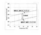
以下、超音波振動子間の距離を好適に設定する方法に関して示す。酸素濃縮ガスの濃度範囲が既知であれば、各温度での流速ゼロにおける酸素濃縮ガス中を伝播する音速の範囲は、式1を用いて容易に計算できる。酸素の分子量を32、窒素の分子量を28、アルゴンの分子量を40、酸素・窒素の比熱比を1.4、アルゴンの比熱比を1.667とすれば、例えば、温度20℃の場合において、酸素濃度21%の場合(酸素が濃縮されていない大気の場合:酸素21%、窒素78%、アルゴン1%とする)の音速は式1より、343.6[m/sec]となる。さらに、本実施例における酸素濃縮装置10の出力する酸素濃度が最大に達する状態は、酸素濃度95%、窒素濃度1%、アルゴン濃度4%となることが判明しており、その場合の音速は、326.4[m/sec]と計算される。すなわち、酸素濃縮ガスの酸素濃度が変化した場合において、20℃における酸素濃縮ガス中の音速は、常に326.4[m/sec]〜343.6[m/sec]の範囲に収まることになり、該範囲の両端を音速の上限、下限とする。酸素濃縮ガスの温度の取り得る範囲である5℃〜35℃において計算される、温度と音速の関係をグラフ化したものを、図5に示す。図5にて明らかなように、音速Cの上限、下限は温度Tの関数として表すことができ、温度Tにおける音速の上限をCmax(T)、下限をCmin(T)とする。
【0021】
次に好適にしたい振動子間距離をLs[m]とする。音速の取り得る範囲が先述の通りあらかじめ分かっているため、超音波伝播時間の取り得る範囲は、Lsを用いて表すことができる。すなわち超音波伝播時間の取り得る範囲は、Ls/Cmax(T)[sec] 〜 Ls/Cmin(T)[sec]である。
【0022】
該超音波伝播時間の取り得る範囲に、ゼロクロス時間検出回路6にて得られる該ゼロクロス時間から1周期の整数倍だけ巻き戻して得られる時間が常に1つだけにするためには、伝播時間の取り得る範囲が超音波の1周期分の時間未満であれば良い(図10)。超音波の周波数をfr[Hz]とすれば、1周期の時間は1/fr[sec]となる。すなわち、下記式3を常に満たすLsを選定すれば良い。
【0023】
【数3】
“Ls/ Cmin(T) − Ls/ Cmax(T)”の値を最大にする温度Tは、本実施例においては酸素濃縮ガスの温度範囲下限の5℃である。5℃におけるCmax(5℃)、Cmin(5℃)はそれぞれ、Cmax(5℃)=334.7[m/sec]、Cmin(5℃)=317.9[m/sec]となる。さらに、本実施例における超音波の周波数frは、fr=40[kHz]=40000[Hz]であるため、式3を満たす振動子間距離Lsは、Ls<15.8[cm]となり、およそ15[cm]未満の振動子間距離となるように2つの超音波振動子2を設置すれば良いことになる。ただし、該振動子間距離をあまりに短くしすぎると、超音波を送受信した際に得られる超音波伝播時間が非常に短くなることとなり、時間計測分解能の面から不利となる。また、計算上の振動子間距離の上限となる15.8cm近傍の振動子間距離を採択した場合、例えば、酸素濃縮ガスの実際の温度が設計上の使用温度下限とした5℃であるにもかかわらず、温度センサ3の出力誤差によって実際よりも低い温度を測定してしまった場合や、酸素濃縮装置10の使用者の不注意によって該酸素濃縮装置10を5℃よりも下回る温度環境下に設置してしまった場合等には、マイクロコンピュータ7における計算上の音速測定値がCmin(5℃)〜Cmax(5℃)の範囲を飛び出してしまうことも考えられる。さらに、超音波振動子2の中心周波数にはバラツキがあり、例えば実際に使用した超音波振動子2の中心周波数が42kHzであった場合には、式(3)による計算結果は15.1cmとなり、理想状態における計算値の15.8cmよりも短い振動子間距離を設定しなければならないことになる。製品として酸素濃縮装置10を実現する場合には、該状況を十分考慮に入れた設計を実施する必要性があり、本実施例においては、現実的に存在しうる使用環境、および、温度センサ3の測定精度やマイクロコンピュータ7の時間測定分解能、超音波振動子2の中心周波数のバラツキ等を考慮した結果、振動子間距離として10[cm]を採用した。
【0025】
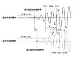
流量を測定するためには、酸素濃縮ガスの流れに対して、順逆双方向に超音波送受信を実施し、順側ゼロクロス時間と逆側ゼロクロス時間の両方を必要とする。順側ゼロクロス時間と逆側ゼロクロス時間が、常に同じトリガ検出位置にて獲得されたものであれば、図6に示すとおり、順側ゼロクロス時間と逆側ゼロクロス時間の差(図6中のAの間隔)=超音波の伝播時間差(図6中のtd)となり得る。図6では、順側ゼロクロス時間、逆側ゼロクロス時間共に、第2波目にてトリガ検出された場合を示している。しかしながら、超音波の受信波形は順逆双方向で全く同一になる保証はなく、ゼロクロス検出回路6内のトリガコンパレ−タで検出されるトリガ検出位置が順逆にて揃わない可能性がある。
【0026】
そこで、順逆双方向にて得られる超音波の伝播時間差tdが、常に受信超音波の1周期分未満の時間となるように酸素濃縮ガスの流れる配管1の内半径を設定すれば、トリガ検出位置が順逆にて揃わなかった場合においても容易にトリガ検出位置を揃えることが可能となる。例えば、酸素濃縮ガスの流れに対して順方向に超音波送受信を実施して得られたトリガ検出位置が第3波目であり、逆方向に超音波送受信した場合に得られたトリガ検出位置が第2波目であった場合を図7に示す。
【0027】
順逆にてトリガ検出位置が揃っていたと仮定して順側ゼロクロス時間と逆側ゼロクロス時間の差を計算すると、その値は負の値となる(図7中のA)。酸素濃縮ガスの流量範囲が0〜10[L/min]であれば、伝播時間の差が負になることはありえないため、容易にトリガ検出位置が揃っていなかったことを検出でき、図7中のBを真の伝播時間差として採択することが可能となる。
【0028】
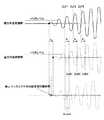
逆に、酸素濃縮ガスの流れに対して順方向に超音波送受信を実施して得られたトリガ検出位置が第2波目であり、逆方向に超音波送受信した場合に得られたトリガ検出位置が第3波目であった場合を図8に示す。順逆にてトリガ検出位置が揃っていたと仮定して順側ゼロクロス時間と逆側ゼロクロス時間の差を計算すると、その値は超音波の1周期分の時間を上回る値となる(図8中のA)。しかしながら、超音波の伝播時間差tdが、常に受信超音波の1周期分未満の時間となるように設計されていれば、伝播時間の差が受信超音波の1周期分以上になることはありえないため、この場合も容易にトリガ検出位置が揃っていなかったことを検出でき、図8中のBを真の伝播時間差として採択することが可能となる。
【0029】
以下、酸素濃縮ガスの流れる配管1の内半径を好適に設定する方法に関して示す。酸素濃縮ガスの流量をQ[L/min]とすれば、酸素濃縮ガスの流れる配管1の内半径をr[m]とした場合、該配管1中の流速V[m/sec]は、次の式4の範囲にて表される。
【0030】
【数4】
酸素濃縮ガスの流れに対して順方向に超音波を送信した場合に観測される音速V1[m/sec]は、酸素濃縮ガスが静止している場合の音速をC[m/sec]として、V1=C+V、また、酸素濃縮ガスの流れに対して逆方向に超音波を送信した場合に観測される音速V2[m/sec]は、V2=C−V、として観測される。酸素濃縮ガスの流れに対して順逆双方向に超音波送受信を実施した際に観測される伝播時間の差をtd[sec]とすると、tdは振動子間距離をLs[m]として、式5で表すことができる。
【0032】
【数5】
したがって、伝播時間の差tdが常に受信超音波の1周期分未満の時間となるようにするためには、常に式6を満たす内半径rを選定すれば良い。
【0034】
【数6】
本実施例において、式6の左項を最大とするC、Qの条件は、C=Cmin(5℃)=317.9[m/sec]、Q=10[LPM]である。さらに、振動子間距離Ls=10[cm]=0.1[m]、超音波の周波数fr=40[kHz]=40000[Hz]を式6に代入すると、r>2.051[mm]となり、配管1の内半径が2.051[mm]を上回るようにすれば良いことになる。該内半径を設定する場合も、振動子間距離を設定する場合と同様、該内半径が大きければ大きいほうが良いというわけではない。該内半径を大きくしていくと、配管1内を流れる酸素濃縮ガスの流速は小さくなっていき、酸素濃縮ガスの流れに対して順逆に超音波を送受信した際に得られる超音波伝播時間の差は小さくなっていくこととなり、時間計測分解能の面から不利となる。また、計算上の下限となる値近傍の内半径を選択した場合にも、振動子間距離を設定する場合と同様に不都合を生じる可能性が高く、本実施例においては、現実的に存在しうる使用環境、および、マイクロコンピュータ7の時間測定分解能、超音波振動子2の中心周波数のバラツキ等を考慮した結果、配管1の内半径として2.5[mm]を採用した。
【0036】
以下、本実施例における酸素濃縮装置10に搭載された超音波式酸素濃度流量測定手段15による酸素濃縮ガスの酸素濃度、および、流量測定方法に関して述べる。コンプレッサ12がフィルタ11を介して原料ガスとして空気を吸い込み、該空気を酸素濃縮手段13に送り込む。酸素濃縮手段13は、空気中から窒素を選択的に吸着することにより酸素濃縮ガスを送り出す。送り出された酸素濃縮ガスは、超音波式酸素濃度流量測定手段15へ投入される。
【0037】
該超音波式酸素濃度流量測定手段15は、酸素濃縮ガス投入中において、マイクロコンピュ−タ7より超音波の送信パルスをドライバ5に送り、送受信切り替え器4によって酸素濃縮ガスの流れと順方向に超音波を送信するように選択された超音波振動子2にパルス電圧が印加され、超音波が送信される。もう一方の超音波振動子2によって受信された超音波は、送受信切り替え器4を介して、ゼロクロス検出回路6に入力され、得られた順側ゼロクロス時間3つ(ZcF1、ZcF2、ZcF3)をマイクロコンピュ−タ7に送る。その後、マイクロコンピュ−タ7より超音波の送信パルスをドライバ5に送り、送受信切り替え器4によって酸素濃縮ガスの流れと逆方向に超音波を送信するように選択された超音波振動子2にパルス電圧が印加され、超音波が送信される。もう一方の超音波振動子2によって受信された超音波は、送受信切り替え器4を介して、ゼロクロス検出回路6に入力され、得られた逆側ゼロクロス時間3つ(ZcB1、ZcB2、ZcB3)をマイクロコンピュ−タ7に送る。
【0038】
以上の操作によって酸素濃縮ガスの流れに対して順逆双方向にて得られた順側ゼロクロス時間と逆側ゼロクロス時間から、図6〜図8に示した方法により、トリガ検出位置を揃えた超音波の伝播時間の差tdを算出する。tdの算出には、図6中に示されたAの値、もしくは、図7、図8中に示されたBの値を加算平均することで、時間検出誤差を減少させることが可能である。さらに、順側ゼロクロス時間と逆側ゼロクロス時間のトリガ検出位置を揃えた最初のゼロクロス時間の平均ゼロクロス時間Zc_aveを算出する。Zc_aveは、酸素濃縮ガスの流量がゼロの時に超音波送受信を行った際に得られるゼロクロス時間であると見なすことができる。例えば図6に示した状態であれば、Zc_aveは次の式7で求めることができる(図9)。
【0039】
【数7】
同様に図7に示した状態であれば、式8にて求めることができる(図示せず)。
【0041】
【数8】
更に図8に示した状態であれば、式9にて求めることができる(図示せず)。
【0043】
【数9】
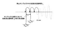
続いて、マイクロコンピュ−タ7は、2つの超音波振動子間の距離をLs[m]とし(本実施例においては、Ls=0.1[m])、温度センサ3の出力T℃を読み取り、酸素濃縮ガスの温度T℃に応じた超音波伝播時間の範囲Ls/Cmax(T)[sec]〜Ls/Cmin(T)[sec]を計算する。さらに、該平均ゼロクロス時間Zc_aveから該超音波伝播時間の範囲に入るまで、受信超音波の1周期分の時間=25[μsec]の整数倍を巻き戻していき、超音波伝播時間ts[sec]を確定する(図10)。この結果より、静止した酸素濃縮ガス中の超音波伝播速度Cs[m/sec]は次式10にて求めることができる。
【0045】
【数10】
静止した酸素濃縮ガス中の超音波伝播速度Csが特定できれば、該酸素濃縮ガスの温度Tも温度センサ3によって既知であるため、例えば特開2003−135601号公報や、特開2003−137510号公報に記載されている方法にて酸素濃度を特定することが可能となる。
【0047】
上記の計算は、マイクロコンピュ−タ7にて実施され、濃度測定結果は表示器8に表示される。
【0048】
流量測定時には、先に求めた静止した酸素濃縮ガス中の超音波伝播時間tsと、超音波伝播時間差tdを用いて、酸素濃縮ガスの流れに対して順方向に超音波の送受信を実施した際の超音波伝播時間ts1、逆方向に超音波の送受信を実施した際の超音波伝播時間ts2を式11、式12によって求める。
【0049】
【数11】
【数12】
すなわち、酸素濃縮ガスの流れに対して順方向に超音波を送信したときに測定される超音波伝播速度Vs1[m/sec]、逆方向に超音波を送信したときに測定される超音波伝播速度Vs2[m/sec]は、それぞれ次式によって求めることができる。
【0052】
【数13】
【数14】
さらに、式2より、酸素濃縮ガスの流速Vs[m/sec]は次式で求めることができる。
【0055】
【数15】
流速Vs[m/sec]が求まれば、酸素濃縮ガスの流れる配管1の内半径をrs[m]とすれば、流量Qs[L/min]は式16によって求めることができる。
【0057】
【数16】
Qs=60000πrs2Vs
【0058】
上記の計算は、マイクロコンピュ−タ7において実施され、流量測定結果は表示器8に表示される。
【図面の簡単な説明】
【図1】本発明の酸素濃縮装置の構成を示す概略図。
【図2】本発明の超音波式酸素濃度流量測定手段の構成を示す概略図。
【図3】超音波受信波形の一例。
【図4】ゼロクロス時間検出回路によるゼロクロス時間検出方法の例。
【図5】温度と音速の関係。
【図6】トリガ検出位置が揃っている場合の超音波伝播時間差とゼロクロス時間の間隔との関係。
【図7】順方向に超音波送受信を実施して得られたトリガ検出位置に対し、逆方向に超音波送受信した場合に得られたトリガ検出位置が1周期分だけ前方であった場合の超音波伝播時間差とゼロクロス時間の間隔との関係。
【図8】順方向に超音波送受信を実施して得られたトリガ検出位置に対し、逆方向に超音波送受信した場合に得られたトリガ検出位置が1周期分だけ後方であった場合の超音波伝播時間差とゼロクロス時間の間隔との関係。
【図9】静止した酸素濃縮ガス中にて超音波送受信を行った際に得られるゼロクロス時間を求める例。
【図10】静止した酸素濃縮ガス中の超音波伝播時間を求める例。
【符号の説明】
1 配管
2 超音波振動子
3 温度センサ
4 送受信切り替え器
5 ドライバ
6 ゼロクロス検出回路
7 マイクロコンピュ−タ
8 表示器
9 不揮発性メモリ
10 酸素濃縮装置
11 フィルタ
12 コンプレッサ
13 酸素濃縮手段
14 流量設定手段
15 超音波式酸素濃度流量測定手段
16 製品フィルタ[0001]
BACKGROUND OF THE INVENTION
The present invention relates to an oxygen concentrator provided with means for measuring the oxygen concentration and flow rate of an oxygen-enriched gas by ultrasonic waves.
[0002]
[Prior art]
It is widely known that the propagation speed of ultrasonic waves propagating in a sample gas is expressed as a function of the concentration and temperature of the sample gas. If the average molecular weight of the sample gas is M and the temperature is T [K], the ultrasonic propagation velocity C [m / sec] in the sample gas is expressed by the following equation.
[0003]
[Expression 1]
Here, k and R are constants (k: ratio of constant volume molar specific heat and constant pressure molar specific heat, R: gas constant). That is, if the ultrasonic propagation velocity C [m / sec] in the sample gas and the temperature T [K] of the sample gas can be measured, the average molecular weight M of the sample gas can be determined. For example, if the sample gas is a gas composed of two molecules of oxygen and nitrogen, it is known that k = 1.4. The average molecular weight M of the sample gas is such that the molecular weight of oxygen is 32 and the molecular weight of nitrogen is 28. For example, oxygen 100 × P [%] (0 ≦ P ≦ 1) and nitrogen 100 × (1−P) [%] In some cases, M = 32 P + 28 (1-P) can be described, and the oxygen concentration P can be determined from the measured average molecular weight M. Also, when the ultrasonic wave velocity in the sample gas is C [m / sec] and the flow velocity of the sample gas is V [m / sec], when ultrasonic waves are transmitted in the forward direction with respect to the sample gas flow The ultrasonic propagation velocity V1 [m / sec] measured at1 is V1 = C + V, and the ultrasonic propagation velocity V2 [m / sec] measured when ultrasonic waves are transmitted in the opposite direction is V2 Since C−V, the flow velocity V [m / sec] of the sample gas can be obtained by the following equation 2.
[0005]
[Expression 2]
By multiplying this by the inner area [m2 ] of the pipe through which the sample gas flows, the flow rate [m3 / sec] of the sample gas can be obtained. Furthermore, if volume conversion and time conversion are performed, the flow rate can be easily obtained in [L / min]. Various proposals have been made regarding methods and apparatuses for measuring the concentration and flow rate of a sample gas from the propagation speed or propagation time of an ultrasonic wave propagating in the sample gas using the principle. For example, in Japanese Patent Laid-Open No. 6-213877, two ultrasonic transducers are arranged facing each other in a pipe through which a sample gas passes, and the propagation time of ultrasonic waves propagating between the ultrasonic transducers is measured. Describes an apparatus for measuring the concentration and flow rate of a sample gas. In Japanese Patent Application Laid-Open Nos. 7-209265 and 8-233718, the propagation speed or propagation time of ultrasonic waves propagating in a sensing area is measured by a sound wave reflection method using one ultrasonic transducer. Thus, an apparatus for measuring the concentration of a sample gas is described. Furthermore, if the number of molecules constituting the sample gas is two, the concentration of the sample gas can be easily specified as described above. However, the oxygen-enriched gas output from the oxygen concentrator includes oxygen In addition to nitrogen, argon is included. The method for specifying the oxygen concentration in that case is described in Japanese Patent Application Laid-Open No. 2003-135601 and Japanese Patent Application Laid-Open No. 2003-137510.
[0007]
[Patent Document 1]
JP-A-6-213877 [Patent Document 2]
Japanese Patent Laid-Open No. 7-209265 [Patent Document 3]
JP-A-8-233718 [Patent Document 4]
JP 2003-135601 A [Patent Document 5]
JP 2003-137510 A [Patent Document 6]
JP-A-9-318644 [Patent Document 7]
Japanese Patent Laid-Open No. 60-138422
[Problems to be solved by the invention]
In such a method and apparatus for accurately measuring the concentration and flow rate of the sample gas using the ultrasonic wave propagation speed, the ultrasonic wave propagation time must be accurately detected. However, noise components are always included in the received waveform of an ultrasonic wave, and it is very difficult to directly detect the time at the moment when the ultrasonic wave is received. A method of estimating the ultrasonic propagation time by installing hardware is used.
[0009]
For example, in Japanese Patent Laid-Open No. 9-318644, the received ultrasonic waveform is integrated, and the zero-cross time of the received wave after the integrated output reaches the reference value is used as the ultrasonic propagation time for flow velocity measurement. A method is described. With this method, even if the amplitude of the received waveform varies slightly, the zero cross timing does not vary, so the zero cross time at a position relatively close to the arrival time of the received wave can be obtained. The difference between the true ultrasonic wave propagation time and the detected zero-crossing time greatly affects the measurement error, particularly in the concentration measurement, not the ultrasonic wave propagation time.
[0010]
Japanese Patent Application Laid-Open No. 60-138422 describes a method for detecting the rise time of the envelope waveform based on the approximate expression calculated from the envelope waveform of the received waveform and setting it as the true ultrasonic wave propagation time. ing. However, in the method of estimating the ultrasonic wave propagation time from the envelope waveform, hardware for sampling the received waveform is required to obtain the envelope waveform, and a complicated signal is required for calculating the envelope. Since processing is required, it has been difficult to produce an inexpensive and small device.
[0011]
The present invention provides a method for measuring the oxygen concentration and flow rate of an oxygen-enriched gas without requiring complicated signal processing and hardware, and an inexpensive and small-sized ultrasonic gas by using only the minimum necessary components. An object of the present invention is to provide an oxygen concentrator equipped with a concentration flow rate measuring means.
[0012]
[Means for Solving the Problems]
As a result of diligent research to achieve such an object, the present inventors have found that an oxygen concentrating means for separating oxygen from the air, and an ultrasonic wave disposed opposite to the piping through which oxygen-enriched gas downstream of the oxygen concentrating means flows. In an oxygen concentrator equipped with two transducers and a zero-crossing time detection circuit for received ultrasonic waves, the speed of sound of ultrasonic waves propagating in the oxygen-enriched gas can be obtained from the concentration range and temperature range that the oxygen-enriched gas can take. If a suitable distance between ultrasonic transducers is set by knowing the range in advance, and if a suitable pipe radius is set from the flow rate range that the oxygen-enriched gas can take, two continuous oxygen-enriched gas temperatures can be obtained. By detecting only the above zero-crossing time, it is possible to detect the ultrasonic propagation time in the stationary oxygen-enriched gas and the flow of oxygen-enriched gas without acquiring the waveform information of the received ultrasound. The ultrasonic wave propagation time difference between the reverse directions can be accurately detected, it has been found the oxygen concentration of the oxygen enriched gas, and that it is possible to measure the flow rate.
[0013]
DETAILED DESCRIPTION OF THE INVENTION
Examples are shown below. In this embodiment, the case where the oxygen concentration range of the oxygen-enriched gas is 21 [% O2 ] to 95 [% O2 ] will be described. When the oxygen concentration is 21 [% O2 ], it is assumed that the atmosphere in which oxygen is not concentrated is measured. Further, the flow range of the oxygen-enriched gas is 0 to 10 [L / min], and the temperature range of the oxygen-enriched gas is shown in the case of 5 [° C.] to 35 [° C.]. In this embodiment, an ultrasonic transducer having a center frequency of 40 [kHz] is used. The concentration range and temperature range that can be taken by the oxygen-enriched gas that can be measured by the present invention are not limited to the ranges in the present embodiment, and can be easily applied to other ranges. Furthermore, the center frequency of the ultrasonic vibrator is not limited to 40 [kHz], and can be easily applied to ultrasonic vibrators having other center frequencies.
[0014]
The configuration of the oxygen concentrator in the present embodiment is as shown in FIG. This example shows an example of a pressure fluctuation adsorption type oxygen concentrator, but various other generating means such as an oxygen-enriched membrane and a solid electrolyte membrane can be adopted as the oxygen generating means. The
[0015]
The configuration of the ultrasonic oxygen concentration flow rate measuring means 15 is as shown in FIG. Two ultrasonic transducers 2 are arranged opposite to each other in a
[0016]
Various methods for detecting the zero-cross time of received ultrasonic waves by transmitting and receiving ultrasonic waves have been proposed. The simplest method is to mount a zero cross comparator and detect the rising edge or falling edge of the comparator output. FIG. 3 shows an example of the ultrasonic reception waveform. Since various noise components are included in the received waveform of the ultrasonic wave, it is desirable to acquire the output of the zero cross comparator when the reception amplitude becomes sufficiently large in order to accurately detect the zero cross time. That is, the acquired zero crossing time is obtained not in the first wave of the received ultrasonic wave but in the second wave or the third wave thereafter. FIG. 4 shows a zero cross time detection method in the zero cross
[0017]
The zero-crossing interval of the received ultrasonic wave should always be a time interval for one cycle calculated from the center frequency. The time for one cycle when using an ultrasonic transducer with a center frequency of 40 [kHz] is 1/40000 [sec] = 25 [μsec]. In other words, the leading zero-crossing time obtained by the zero-crossing
[0018]
That is, even if it is unclear how many times the zero-crossing time acquired is the zero-crossing time after the first wave, it is rewound by an integral multiple of one cycle from the zero-crossing time within the possible range of the ultrasonic propagation time described above. By setting the inter-vibrator distance L in which only one time is always obtained, the true ultrasonic wave propagation time can be easily estimated.
[0019]
If the exact frequency of the received ultrasound is not known in advance, it is possible to calculate the interval between each zero-crossing time by acquiring several consecutive zero-crossing times, and calculate the frequency from the interval between the zero-crossing times. You can also.
[0020]
Hereinafter, a method for suitably setting the distance between the ultrasonic transducers will be described. If the concentration range of the oxygen-enriched gas is known, the range of the speed of sound propagating through the oxygen-enriched gas at a flow rate of zero at each temperature can be easily calculated using
[0021]
Next, let Ls [m] be the distance between the transducers that is desired to be suitable. Since the possible range of the sound velocity is known in advance as described above, the possible range of the ultrasonic propagation time can be expressed using Ls . That is, the possible range of the ultrasonic wave propagation time is Ls / Cmax (T) [sec] to Ls / Cmin (T) [sec].
[0022]
In order to always have only one time obtained by rewinding from the zero cross time obtained by the zero cross
[0023]
[Equation 3]
The temperature T that maximizes the value of “Ls / Cmin (T) −Ls / Cmax (T)” is 5 ° C., which is the lower limit of the temperature range of the oxygen-enriched gas in this embodiment. Cmax (5 ° C.) and Cmin (5 ° C.) at 5 ° C. are Cmax (5 ° C.) = 334.7 [m / sec] and Cmin (5 ° C.) = 317.9 [m / sec], respectively. Furthermore, since the frequency fr of the ultrasonic wave in this embodiment is fr = 40 [kHz] = 40000 [Hz], the inter-vibrator distance Ls satisfying Expression 3 is Ls <15.8 [cm], which is approximately Two ultrasonic transducers 2 may be installed so that the inter-vibrator distance is less than 15 [cm]. However, if the inter-vibrator distance is too short, the ultrasonic wave propagation time obtained when ultrasonic waves are transmitted and received becomes very short, which is disadvantageous in terms of time measurement resolution. In addition, when the inter-vibrator distance near 15.8 cm, which is the upper limit of the inter-vibrator distance in calculation, is adopted, for example, the actual temperature of the oxygen-enriched gas is 5 ° C, which is the lower limit of the use temperature in the design. Regardless, if the temperature of the temperature sensor 3 is lower than the actual temperature due to the output error of the temperature sensor 3 or if the user of the
[0025]
In order to measure the flow rate, ultrasonic transmission / reception is performed in both forward and reverse directions with respect to the flow of the oxygen-enriched gas, and both the forward zero cross time and the reverse zero cross time are required. If the forward-side zero-crossing time and the backward-side zero-crossing time are always acquired at the same trigger detection position, as shown in FIG. 6, the difference between the forward-side zero-crossing time and the backward-side zero-crossing time (A in FIG. Interval) = Ultrasonic propagation time difference (td in FIG. 6). FIG. 6 shows a case where the trigger is detected in the second wave for both the forward zero cross time and the reverse zero cross time. However, there is no guarantee that the received waveforms of ultrasonic waves will be exactly the same in both forward and reverse directions, and the trigger detection positions detected by the trigger comparator in the zero
[0026]
Therefore, the ultrasonic propagation time difference td obtained by the forward and reverse two-way, always by setting the inner radius of the
[0027]
If the difference between the forward zero cross time and the reverse zero cross time is calculated on the assumption that the trigger detection positions are aligned in the forward and reverse directions, the value becomes a negative value (A in FIG. 7). If the flow range of the oxygen-enriched gas is 0 to 10 [L / min], the difference in propagation time cannot be negative, so it can be easily detected that the trigger detection positions are not aligned. B can be adopted as the true propagation time difference.
[0028]
Conversely, the trigger detection position obtained by performing ultrasonic transmission / reception in the forward direction with respect to the flow of the oxygen-enriched gas is the second wave, and the trigger detection position obtained when ultrasonic transmission / reception is performed in the reverse direction. FIG. 8 shows a case where is the third wave. If the difference between the forward zero cross time and the reverse zero cross time is calculated on the assumption that the trigger detection positions are aligned in the forward and reverse directions, the value exceeds the time of one ultrasonic cycle (A in FIG. 8). ). However, if the ultrasonic propagation time difference td is always designed to be less than one period of the received ultrasonic wave, the difference in propagation time cannot be more than one period of the received ultrasonic wave. Therefore, also in this case, it can be easily detected that the trigger detection positions are not aligned, and B in FIG. 8 can be adopted as a true propagation time difference.
[0029]
Hereinafter, a method for suitably setting the inner radius of the
[0030]
[Expression 4]
The velocity of sound V1 [m / sec] observed when ultrasonic waves are transmitted in the forward direction with respect to the flow of oxygen-enriched gas is defined as C [m / sec] when the oxygen-enriched gas is stationary. , V1 = C + V, and the sound velocity V2 [m / sec] observed when transmitting ultrasonic waves in the opposite direction to the flow of oxygen-enriched gas is observed as V2 = C−V. Is done. When td [sec] is the difference in propagation time observed when ultrasonic transmission / reception is performed in both forward and reverse directions for the flow of oxygen-enriched gas, td is the distance between the transducers Ls [m]. , Can be represented by
[0032]
[Equation 5]
Therefore, in order to ensure that the difference in propagation time td is always less than one period of the received ultrasonic wave, it is sufficient to always select an inner radius r that satisfies
[0034]
[Formula 6]
In the present embodiment, the conditions of C and Q that maximize the left term of
[0036]
Hereinafter, the oxygen concentration of the oxygen-enriched gas and the flow rate measuring method by the ultrasonic oxygen concentration flow rate measuring means 15 mounted on the
[0037]
The ultrasonic oxygen concentration flow rate measuring means 15 sends an ultrasonic transmission pulse from the
[0038]
From the forward zero-cross time and the reverse zero-cross time obtained in the forward and reverse directions with respect to the flow of the oxygen-enriched gas by the above operation, the ultrasonic waves whose trigger detection positions are aligned by the method shown in FIGS. to calculate the difference td of the propagation time. In calculating td , the time detection error can be reduced by averaging the values of A shown in FIG. 6 or the values of B shown in FIGS. is there. Further, an average zero cross time Zc_ave of the first zero cross time in which the trigger detection positions of the forward zero cross time and the reverse zero cross time are aligned is calculated. Zc_ave can be regarded as a zero cross time obtained when ultrasonic transmission / reception is performed when the flow rate of the oxygen-enriched gas is zero. For example, in the state shown in FIG. 6, Zc_ave can be obtained by the following Expression 7 (FIG. 9).
[0039]
[Expression 7]
Similarly, if it is in the state shown in FIG. 7, it can obtain | require by Formula 8 (not shown).
[0041]
[Equation 8]
Furthermore, if it is in the state shown in FIG. 8, it can obtain | require by Formula 9 (not shown).
[0043]
[Equation 9]
Subsequently, the
[0045]
[Expression 10]
If the ultrasonic propagation velocity Cs in the stationary oxygen-enriched gas can be specified, the temperature T of the oxygen-enriched gas is also known by the temperature sensor 3, so that, for example, JP 2003-135601 A or JP 2003-137510 A The oxygen concentration can be specified by the method described in the publication.
[0047]
The above calculation is performed by the
[0048]
When the flow rate measurement, the ultrasonic wave propagation time ts of the oxygen enriched gas at rest previously obtained using the ultrasonic wave propagation time difference td, implementing transmission and reception of ultrasonic waves in the forward direction to the flow of oxygen enriched gas The ultrasonic propagation time ts1 when the ultrasonic wave is transmitted and the ultrasonic propagation time ts2 when the ultrasonic wave is transmitted / received in the opposite direction are obtained by
[0049]
[Expression 11]
[Expression 12]
That is, the ultrasonic wave velocity Vs1 [m / sec] measured when ultrasonic waves are transmitted in the forward direction with respect to the flow of the oxygen-enriched gas, and the ultrasonic wave measured when ultrasonic waves are transmitted in the reverse direction The propagation velocity Vs2 [m / sec] can be obtained by the following equations, respectively.
[0052]
[Formula 13]
[Expression 14]
Furthermore, from Equation 2, the flow velocity Vs [m / sec] of the oxygen-enriched gas can be obtained by the following equation.
[0055]
[Expression 15]
If the flow velocity Vs [m / sec] is obtained, the flow rate Qs [L / min] can be obtained by
[0057]
[Expression 16]
Qs = 60000πrs2 Vs
[0058]
The above calculation is performed in the
[Brief description of the drawings]
FIG. 1 is a schematic diagram showing the configuration of an oxygen concentrator of the present invention.
FIG. 2 is a schematic diagram showing the configuration of ultrasonic oxygen concentration flow rate measuring means of the present invention.
FIG. 3 shows an example of an ultrasonic reception waveform.
FIG. 4 shows an example of a zero cross time detection method by a zero cross time detection circuit.
FIG. 5 shows the relationship between temperature and sound speed.
FIG. 6 shows the relationship between the ultrasonic propagation time difference and the zero-cross time interval when the trigger detection positions are aligned.
FIG. 7 is a diagram illustrating a case where the trigger detection position obtained when ultrasonic transmission / reception is performed in the reverse direction is one period ahead of the trigger detection position obtained by performing ultrasonic transmission / reception in the forward direction. Relationship between sound wave propagation time difference and zero crossing time interval.
FIG. 8 is a diagram illustrating a case where the trigger detection position obtained when ultrasonic transmission / reception is performed in the reverse direction is behind the trigger detection position obtained by performing ultrasonic transmission / reception in the forward direction; Relationship between sound wave propagation time difference and zero crossing time interval.
FIG. 9 shows an example of obtaining a zero cross time obtained when ultrasonic transmission / reception is performed in a stationary oxygen-enriched gas.
FIG. 10 shows an example of obtaining ultrasonic propagation time in a stationary oxygen-enriched gas.
[Explanation of symbols]
DESCRIPTION OF
Claims (3)
Translated fromJapanese超音波振動子間の距離が、酸素濃縮ガスの温度の取り得る範囲および酸素濃縮ガスの濃度の取り得る範囲から、それらの条件下で超音波伝播速度の取り得る範囲を求め、そこから計算される静止した酸素濃縮ガス中での超音波伝播時間の取り得る範囲の幅が受信超音波の1周期分の時間未満になるように設定されており、
配管の内半径が、酸素濃縮ガスの温度の取り得る範囲、酸素濃縮ガスの濃度の取り得る範囲、および酸素濃縮ガスの流量の取り得る範囲に基づいて、酸素濃縮ガスの流れに対して順逆双方向にて得られる超音波伝播時間の差が、受信超音波の1周期分の時間未満になるように設定されている酸素濃縮装置。Oxygen concentrating means for separating oxygen from the air, atemperature sensor and two ultrasonic transducers arranged opposite to each other in a pipe through which oxygen-enriched gas downstream of the oxygen concentrating means is provided, and a zero-crossing time detecting means for receiving ultrasonic waves In the oxygen concentrator, the zero-crossing time detecting means includes two or more continuous forward zero-crossing times from the received waveform of ultrasonic waves transmitted and received in the forward direction with respect to the flow of oxygen-enriched gas, and the flow of oxygen-enriched gas Two or more consecutive reverse zero-cross times are detected from the received waveform of ultrasonic waves transmitted and received in the opposite direction, and the trigger detection positions of the forward zero-cross time and the reverse zero-cross time are aligned to detect the trigger. calculates an average zero cross time from the average value of the forward side zero crossing time of uniform position on the opposite side zero crossing time,the possible range of the concentration of the oxygen-enriched gas, oxygen enriched gas Temperature, and trueis determined from the distance between the ultrasonic transducers to fall possible range of ultrasonic wave propagation time, the average zero crossing time from the reception of one period of time of ultrasonic integral multiple unwinding true byAn oxygen concentrator comprising a calculation means forcalculating an ultrasonic propagation time andfurther calculatingan oxygen concentration of the oxygen-enriched gas and / or a flow rate of the oxygen-enriched gas,
The distance between the ultrasonic transducers is calculated from the range that the temperature of the oxygen-enriched gas can take and the range that the concentration of the oxygen-enriched gas can take, and the range that the ultrasonic propagation velocity can take under those conditions. The width of the possible range of ultrasonic propagation time in the stationary oxygen-enriched gas is set to be less than the time of one cycle of the received ultrasonic wave,
The inner radius of the pipe is both forward and reverse with respect to the flow of the oxygen-enriched gas, based on the range that the oxygen-enriched gas temperature can take, the range that the oxygen-enriched gas concentration can take, and the range that the oxygen-enriched gas flow can take The oxygen concentrator is set so that the difference in ultrasonic propagation time obtained in the direction is less than the time of one cycle of the received ultrasonic wave .
L/Cmin(Tmin)−L/Cmax(Tmin)<1/fr
但し、
Cmin(Tmin): 酸素濃縮ガスの温度下限値(Tmin℃)において、酸素濃縮ガスの濃度範囲から計算される静止酸素濃縮ガス中を伝播する超音波の理論的音速範囲の下限値[m/sec]
Cmax(Tmin): 酸素濃縮ガスの温度下限値(Tmin℃)において、酸素濃縮ガスの濃度範囲から計算される静止酸素濃縮ガス中を伝播する超音波の理論的音速範囲の上限値[m/sec]
fr: 酸素濃縮ガス中を伝播する超音波の受信周波数[Hz]The distance between the ultrasonic transducers (L) is an oxygen concentrator accordingto請 Motomeko1that meet theconditions of the following equation.
L / Cmin (Tmin ) −L / Cmax (Tmin ) <1 / fr
However,
Cmin (Tmin ): Lower limit value of the theoretical sound velocity range of the ultrasonic wave propagating through the stationary oxygen enriched gas calculated from the concentration range of the oxygen enriched gas at the temperature lower limit value (Tmin ° C) of the oxygen enriched gas [ m / sec]
Cmax (Tmin ): Upper limit value of the theoretical sound velocity range of ultrasonic waves propagating in the stationary oxygen enriched gas calculated from the concentration range of the oxygen enriched gas at the temperature lower limit value (Tmin ° C) of the oxygen enriched gas [ m / sec]
fr: reception frequency [Hz] of ultrasonic waves propagating in the oxygen-enriched gas
L/(Cmin(Tmin)−Qmax/(60000πr2))−
L/(Cmin(Tmin)+Qmax/(60000πr2))<1/fr
但し、
L: 超音波振動子間の距離
Cmin(Tmin): 酸素濃縮ガスの温度下限値(Tmin℃)において、酸素濃縮ガスの濃度範囲から計算される静止酸素濃縮ガス中を伝播する超音波の理論的音速範囲の下限値[m/sec]
Qmax: 酸素濃縮ガスの流量上限値[L/min]
fr: 酸素濃縮ガス中を伝播する超音波の受信周波数[Hz]Inner radius of the pipe (r) is the oxygen concentrator according to請 Motomeko 1or 2satisfying the condition of thefollowing expression.
L / (Cmin (Tmin ) −Qmax / (60000πr2 )) −
L / (Cmin (Tmin ) + Qmax / (60000πr2 )) <1 / fr
However,
L: Distance between ultrasonic transducers Cmin (Tmin ): ultrasonic wave propagating through the stationary oxygen-enriched gas calculated from the concentration range of the oxygen-enriched gas at the lower temperature limit of the oxygen-enriched gas (Tmin ° C) Lower limit of the theoretical sound speed range [m / sec]
Qmax : Upper limit flow rate of oxygen-enriched gas [L / min]
fr: reception frequency [Hz] of ultrasonic waves propagating in the oxygen-enriched gas
Priority Applications (17)
| Application Number | Priority Date | Filing Date | Title |
|---|---|---|---|
| JP2003168911AJP4275466B2 (en) | 2003-06-13 | 2003-06-13 | Oxygen concentrator |
| US10/550,687US7213468B2 (en) | 2003-04-21 | 2004-04-20 | Ultrasonic apparatus and method for measuring the concentration and flow rate of gas |
| KR1020057019757AKR101060541B1 (en) | 2003-04-21 | 2004-04-20 | Ultrasonic apparatus and method for measuring the concentration and flow rate of gas |
| KR1020117007542AKR101118945B1 (en) | 2003-04-21 | 2004-04-20 | Ultrasonic apparatus and method for measuring the concentration and flow rate of gas |
| CA2520563ACA2520563C (en) | 2003-04-21 | 2004-04-20 | Ultrasonic apparatus and method for measuring the concentration and flow rate of gas |
| EP11166173.2AEP2366981B1 (en) | 2003-04-21 | 2004-04-20 | Oxygen concentration system for generating oxygen-enriched gas |
| AU2004233273AAU2004233273C1 (en) | 2003-04-21 | 2004-04-20 | Ultrasonic apparatus and method for measuring the concentration and flow rate of gas |
| CA2776083ACA2776083C (en) | 2003-04-21 | 2004-04-20 | Ultrasonic apparatus and method for measuring the concentration and flow rate of gas |
| HK06104764.0AHK1083364B (en) | 2003-04-21 | 2004-04-20 | Ultrasonic apparatus and method for measuring the concentration and flow rate of gas |
| ES04728397.3TES2565635T3 (en) | 2003-04-21 | 2004-04-20 | Ultrasonic device and method for measuring gas concentration and flow |
| HK06110110.8AHK1089813B (en) | 2003-04-21 | 2004-04-20 | Ultrasonic apparatus and method for measuring the concentration and flow rate of gas |
| PCT/JP2004/005590WO2004094960A2 (en) | 2003-04-21 | 2004-04-20 | Ultrasonic apparatus and method for measuring the concentration and flow rate of gas |
| EP04728397.3AEP1616153B1 (en) | 2003-04-21 | 2004-04-20 | Ultrasonic apparatus and method for measuring the concentration and flow rate of gas |
| ES11166173.2TES2600525T3 (en) | 2003-04-21 | 2004-04-20 | Oxygen concentration system to generate oxygen enriched gas |
| TW093111105ATWI280363B (en) | 2003-04-21 | 2004-04-21 | Ultrasonic apparatus and method for measuring the concentration and flow rate of gas |
| MYPI20041447AMY142630A (en) | 2003-04-21 | 2004-04-21 | Ultrasonic apparatus and method for measuring the concentration and flow rate of gas |
| KR1020097012328AKR101118949B1 (en) | 2003-04-21 | 2008-10-07 | Formed article for vehicle body structural member |
Applications Claiming Priority (1)
| Application Number | Priority Date | Filing Date | Title |
|---|---|---|---|
| JP2003168911AJP4275466B2 (en) | 2003-06-13 | 2003-06-13 | Oxygen concentrator |
Publications (2)
| Publication Number | Publication Date |
|---|---|
| JP2005001956A JP2005001956A (en) | 2005-01-06 |
| JP4275466B2true JP4275466B2 (en) | 2009-06-10 |
Family
ID=34094207
Family Applications (1)
| Application Number | Title | Priority Date | Filing Date |
|---|---|---|---|
| JP2003168911AExpired - LifetimeJP4275466B2 (en) | 2003-04-21 | 2003-06-13 | Oxygen concentrator |
Country Status (1)
| Country | Link |
|---|---|
| JP (1) | JP4275466B2 (en) |
Families Citing this family (4)
| Publication number | Priority date | Publication date | Assignee | Title |
|---|---|---|---|---|
| CN101680859B (en)* | 2007-05-31 | 2013-01-02 | 帝人制药株式会社 | Ultrasonic gas concentration measuring method and device using the same |
| JP7675577B2 (en)* | 2021-07-09 | 2025-05-13 | アズビル株式会社 | Anomaly detection device and anomaly detection method |
| JP7675578B2 (en)* | 2021-07-09 | 2025-05-13 | アズビル株式会社 | Ultrasonic flowmeter and flow rate calculation method |
| JP7675579B2 (en)* | 2021-07-09 | 2025-05-13 | アズビル株式会社 | Ultrasonic flowmeter and flow rate calculation method |
- 2003
- 2003-06-13JPJP2003168911Apatent/JP4275466B2/ennot_activeExpired - Lifetime
Also Published As
| Publication number | Publication date |
|---|---|
| JP2005001956A (en) | 2005-01-06 |
Similar Documents
| Publication | Publication Date | Title |
|---|---|---|
| KR101060541B1 (en) | Ultrasonic apparatus and method for measuring the concentration and flow rate of gas | |
| EP0100584B1 (en) | Ultrasonic flowmeter | |
| US5627323A (en) | Ultrasonic binary gas measuring device | |
| JP3023569B2 (en) | Method and apparatus for digitally measuring acoustic burst transit time in a fluid medium | |
| JP5402620B2 (en) | Flow measuring device | |
| JP2987156B2 (en) | Speed measuring device | |
| JP4724714B2 (en) | Acoustic flow meter calibration method | |
| JP4271979B2 (en) | Ultrasonic gas concentration flow measurement method and apparatus | |
| WO2004048902A1 (en) | Ultrasonic flowmeter and ultrasonic flow rate measuring method | |
| JP4556253B2 (en) | Flowmeter | |
| JP4588508B2 (en) | Gas flow rate and gas concentration measurement device using ultrasonic propagation time measurement method | |
| JP2793133B2 (en) | Through-flow volume measuring device | |
| JP2002214012A (en) | Ultrasonic gas concentration and flow rate measuring method and apparatus thereof | |
| JP2007187506A (en) | Ultrasonic flow meter | |
| JP4275466B2 (en) | Oxygen concentrator | |
| JP2007530933A (en) | Zero-crossing detection of ultrasonic signals with variable threshold | |
| JP2003014515A (en) | Ultrasonic flow meter | |
| JP4976287B2 (en) | Detection of ultrasonic signal reception point by pulse waveform detection | |
| JPH1144563A (en) | Flow measurement device | |
| JP4266117B2 (en) | Ultrasonic flow meter | |
| JP4255757B2 (en) | Ultrasonic flow meter | |
| JP3624743B2 (en) | Ultrasonic flow meter | |
| JP4278171B1 (en) | Ultrasonic flow meter and flow measurement method | |
| JP4234838B2 (en) | Ultrasonic flow meter | |
| JP3651110B2 (en) | Ultrasonic current meter |
Legal Events
| Date | Code | Title | Description |
|---|---|---|---|
| A621 | Written request for application examination | Free format text:JAPANESE INTERMEDIATE CODE: A621 Effective date:20060120 | |
| A131 | Notification of reasons for refusal | Free format text:JAPANESE INTERMEDIATE CODE: A131 Effective date:20081125 | |
| A521 | Request for written amendment filed | Free format text:JAPANESE INTERMEDIATE CODE: A523 Effective date:20090126 | |
| TRDD | Decision of grant or rejection written | ||
| A01 | Written decision to grant a patent or to grant a registration (utility model) | Free format text:JAPANESE INTERMEDIATE CODE: A01 Effective date:20090210 | |
| A01 | Written decision to grant a patent or to grant a registration (utility model) | Free format text:JAPANESE INTERMEDIATE CODE: A01 | |
| A61 | First payment of annual fees (during grant procedure) | Free format text:JAPANESE INTERMEDIATE CODE: A61 Effective date:20090304 | |
| R150 | Certificate of patent or registration of utility model | Ref document number:4275466 Country of ref document:JP Free format text:JAPANESE INTERMEDIATE CODE: R150 Free format text:JAPANESE INTERMEDIATE CODE: R150 | |
| FPAY | Renewal fee payment (event date is renewal date of database) | Free format text:PAYMENT UNTIL: 20120313 Year of fee payment:3 | |
| FPAY | Renewal fee payment (event date is renewal date of database) | Free format text:PAYMENT UNTIL: 20130313 Year of fee payment:4 | |
| FPAY | Renewal fee payment (event date is renewal date of database) | Free format text:PAYMENT UNTIL: 20130313 Year of fee payment:4 | |
| EXPY | Cancellation because of completion of term |