JP4271903B2 - Mobile communication system and mobile communication method - Google Patents
Mobile communication system and mobile communication methodDownload PDFInfo
- Publication number
- JP4271903B2 JP4271903B2JP2002173353AJP2002173353AJP4271903B2JP 4271903 B2JP4271903 B2JP 4271903B2JP 2002173353 AJP2002173353 AJP 2002173353AJP 2002173353 AJP2002173353 AJP 2002173353AJP 4271903 B2JP4271903 B2JP 4271903B2
- Authority
- JP
- Japan
- Prior art keywords
- base station
- signal
- reception quality
- mobile station
- mobile
- Prior art date
- Legal status (The legal status is an assumption and is not a legal conclusion. Google has not performed a legal analysis and makes no representation as to the accuracy of the status listed.)
- Expired - Fee Related
Links
Images


Landscapes
- Mobile Radio Communication Systems (AREA)
- Detection And Prevention Of Errors In Transmission (AREA)
Description
Translated fromJapanese【0001】
【発明の属する技術分野】
本発明は、移動体通信システム、移動体通信方法、基地局及び移動局に係り、より詳しくは、移動局と複数のアンテナを備えた基地局とを含んで構成され、移動局からの自動再送要求に基づく基地局による信号の再送制御を含む信号送受信制御を行う移動体通信システム、当該移動体通信システムにて実行される移動体通信方法、当該移動体通信システムを構成する基地局及び移動局に関する。
【0002】
また、本発明は、移動体通信システムにおける信号送信方法及びシステムに係り、詳しくは、自動再送要求を行いながら信号の送受信を行う移動体通信システムにおいて、移動局における受信品質を向上するようにチャネルを変更して信号を送信する信号送信方法及びシステムに関する。
【0003】
更に、本発明は、かかる信号送信方法に従って通信を行う基地局に関する。
また、本発明は、かかる信号送信方法に従って通信を行う移動局に関する。
【0004】
【従来の技術】
図13には従来の移動体通信システム10のブロック構成図を、図14には従来の自動再送要求での移動体通信システムの連携動作を説明するための図を示す。基地局1では、データ入力端6から入力される移動局11宛てのデータをARQ(Automatic Repeat Request)処理器2に入力する。該ARQ処理器2では、伝送中に生じる誤りを検出できるようにCRC(Cyclic Redundancy Checking)などの誤り検出可能なパリティを付加した後に、該データを記憶する(図14のA1)と共に送信機3に出力する。送信機3は、入力したデータを送信信号に変調した後に、送受分波器4を介して基地局第1アンテナ7から下りリンク22を介して移動局11へ送信する(A2)。
【0005】
移動局11では、移動局アンテナ17からの信号を送受分波器16を介して受信機12に入力する。そして受信機12で受信した信号を受信データとしてARQ処理器13に入力する(A3)。ARQ処理器13は、CRCを用いて誤りの検出を行う(A4)。
【0006】
ここで受信データに誤りが検出されない場合、ARQ処理器13は、受信データをデータ出力端14から出力すると共に該受信データの到達確認を送信機15に出力する。送信機15は、該受信データの到達確認を上りリンク21を介して基地局1のARQ処理器2に通知する(A5)。そして到達確認の通知を受けたARQ処理器2は、再送のために記憶しておいた該データを削除する(A7及びA8)。
【0007】
一方、A4で受信データに誤りが検出された場合、ARQ処理器13は該受信データの再送要求を上りリンク21を介して基地局1のARQ処理器2に通知する(A6)。そして再送要求の通知を受けたARQ処理器2は、要求されたデータを基地局第1アンテナ7から再送する(A7及びA9)。
【0008】
また、図15及び図16は、従来の移動体通信システムの構成図及び動作を説明するためのフローチャートである。図15に示すように、従来の移動体通信システムは、基地局21及び移動局31から構成される。
【0009】
基地局21は、ARQ(Automatic Repeat Request)処理器22と、送受信機23と、信号入力端24と、基地局アンテナ25とを具備して構成される。一方の移動局31は、送受信機32と、ARQ処理器33と、信号出力端34と、移動局アンテナ35とを具備して構成される。
【0010】
以下、従来の移動体通信システムの動作を図16のフローチャートを参照しながら説明する。
基地局21では、信号入力端24から入力される移動局31宛の信号をARQ処理器器22に入力する。該ARQ処理器22は、伝送中に生じる誤りを検出できるようにCRC(Cyclic Redundancy Checking)などの誤り検出可能なパリティを付加した後、該信号を記憶(B1)すると共に送受信機23に出力する。送受信機23は、信号の送信開始を移動局に報知(B2)した後に、該移動局宛の信号送信用として決められている周波数チャネルである下りリンク42を介して信号を該移動局31に送信する(B3)。
【0011】
移動局31では、移動局アンテナ35で受信した下りリンク42の信号を送受信機32で受信(B4)した後に、ARQ処理器33に入力する。ARQ処理器33は、CRCを用いて受信した信号の誤り検出を行う。そして、該受信信号に誤りが検出されない場合(B5でNO)、該受信信号を信号出力端34から出力すると共に、該受信信号の到達確認を上りリンク41を介して基地局のARQ処理器22に通知(B6)する。その後、該到達確認を受信した該ARQ処理器22は、再送のために記憶している該信号を削除する(B8でNO、及びB9)。
【0012】
一方、受信信号に誤りが検出された場合(B5でYES)、ARQ処理器33は該受信信号の再送要求を上りリンク41を介して基地局のARQ処理器22に通知(B7)する。そして、再送要求の通知を受けた該ARQ処理器22は要求された信号をさきほど送信に用いた周波数チャネルで再送する(B8でYES、及びB10)。
【0013】
【発明が解決しようとする課題】
しかしながら、図13及び図14を参照して説明した従来の移動体通信システムにおける自動再送要求での高品質信号送信の方法では、常に同一の基地局アンテナを用いて送信するため、受信アンテナダイバーシチを実現できないような簡易な移動局、又は同一場所に長く滞在する移動局では、フェージング又はシャドーイングの影響による低受信品質状態が継続されるため再送要求が繰り返されてスループットが低下する問題があった。
【0014】
また、図15及び図16を参照して説明したように、従来の移動体通信システムでは、基地局は、決められている該移動局宛の信号送信用の周波数チャネルでのみ送信するため、受信アンテナダイバーシチを実現できないような簡易な移動局、または同一場所に長く潜在する移動局ではフェージング又はシャドーイングの影響により低受信品質のままとなり、再送要求が繰り返されてスループットが低下する問題があった。
【0015】
そこで、本発明の課題は、移動局からの再送要求の繰返しを減少させてスループットを向上することである。
【0016】
【課題を解決するための手段】
前記課題を解決するために、本発明に係る移動体通信システムは、請求項1に示すように、移動局と基地局とから構成され、自動再送要求を行いながら信号の送受信を行う移動体通信システムにおいて、前記移動局は、基地局から送信される無線信号の受信品質を測定する受信品質測定手段と、該測定された無線信号の受信品質に基づいて、受信品質に適合する無線リソースの使用を要求する無線リソース使用要求を前記基地局に送信する要求送信手段とを備え、前記基地局は、前記無線リソース使用要求を受信する要求受信手段と、前記無線リソース使用要求により要求された無線リソースを用いて、前記自動再送要求により再送を要求された信号を含む前記移動局宛の信号を送信する信号送信手段とを備え、前記信号送信手段は、同一のマルチキャストデータに対して再送要求を行った移動機の数である再送要求数が多い順に無線リソースを使用して信号を送信することを特徴とする。
【0033】
請求項2記載の移動体通信方法は、複数の移動局と、複数のアンテナを備えた基地局とを含んで構成された移動体通信システムにて実行され、移動局からの自動再送要求に基づく基地局による信号の再送制御を含む信号送受信制御を行う移動体通信方法であって、前記移動局にて、前記基地局の複数のアンテナから送信された信号の受信品質を測定する品質測定工程と、前記移動局にて、前記測定により得られた各アンテナからの信号の受信品質に基づいて、前記複数のアンテナの内、少なくとも1つのアンテナからのマルチキャスト信号の送信を要求する旨のアンテナ使用要求を前記基地局に送信する要求送信工程と、前記基地局にて、前記複数のアンテナの内、少なくとも1つのアンテナからのマルチキャスト信号の送信を要求する旨のアンテナ使用要求を受信する要求受信工程と、前記基地局にて、前記アンテナ使用要求により要求されたアンテナから、前記自動再送要求により再送を要求されたマルチキャスト信号を含む前記複数の移動局宛てのマルチキャスト信号を送信するマルチキャスト信号送信工程と、を備え、前記マルチキャスト信号送信工程では、複数の移動局からのアンテナ使用要求が複数アンテナにわたって存在する場合、前記基地局は、同一のマルチキャストデータに対して再送要求を行った移動機の数である再送要求数が多い順にアンテナを使用してマルチキャスト信号を送信することを特徴としている。
【0065】
更に、本発明は、請求項5に記載されるように、移動局と基地局から構成されて、自動再送要求を行いながら信号の送受信を行う移動体通信システムにおいて、
前記移動局は、基地局から送信される無線信号の受信品質を測定する受信品質測定手段と、該測定された無線信号の受信品質を基地局に通知する受信品質通知手段とを備え、前記基地局は、前記移動局から再送要求された信号を該移動局から通知された受信品質に基づいて該移動局が所要の受信品質を満たすように送信する送信手段を備え、前記受信品質通知手段は、受信した信号の再送要求が必要なときに、前記測定された無線信号の受信品質と共に、前記再送要求を前記基地局に対して通知し、前記送信手段は、同一のマルチキャストデータに対して再送要求を行った移動機の数である再送要求数が多い順に無線リソースを使用して信号を送信するように構成される。
また、本発明は、請求項6に示されるように、移動局と基地局から構成されて、自動再送要求を行いながら信号の送受信を行う移動体通信システムにおいて、前記移動局は、基地局から送信される無線信号の受信品質を測定する受信品質測定手段と、該測定された無線信号の受信品質を基地局に通知する受信品質通知手段とを備え、前記基地局は、前記移動局から再送要求された信号を該移動局から通知された受信品質に基づいて該移動局が所要の受信品質を満たすように送信する送信手段を備え、前記受信品質通知手段は、受信した信号の到達確認を前記基地局に通知する際に、前記測定した複数又は単一の無線チャネルの受信品質を該基地局に通知し、前記送信手段は、同一のマルチキャストデータに対して再送要求を行った移動機の数である再送要求数が多い順に無線リソースを使用して信号を送信するように構成される。
【0066】
請求項1に記載の移動体通信システムと、請求項5又は6に記載の移動体通信システムとは、受信品質に基づいて無線リソースを決定する主体が、前者は移動局側、後者は基地局側である点において異なるものであり、それぞれ同様の技術的思想に属するものである。
【0069】
以下、本発明をより充分に理解できる様に、詳細な説明及び添付図面を例示するが、本発明はこれらの記載に限定されるものではない。
更に、本発明の好適な範囲は、以下に示す詳細な説明から明確になる。但し、この詳細な説明は、本発明の実施態様の好適な数例を示すものに過ぎず、詳細な説明から明白に導き出される技術内容に基づいて、本発明の趣旨や目的を逸脱しない範囲で適宜様々な変形態様及び修正態様を採ることも可能である。
【0071】
更に、請求項5又は6に示す移動体通信システムでは、前記送信手段は、移動局からの再送要求数が多い順に無線リソースを使用して信号を送信する。
【0073】
【発明の実施の形態】
以下、添付図面を参照して本発明の実施形態を詳細に説明する。
[第1の実施形態]
本発明の第1実施形態について図1〜図3を用いて説明する。ここでは基地局アンテナを2本とした場合について説明するが、本発明は、該基地局アンテナを何本用いても実現可能である。
【0074】
まず、移動体通信システムの構成を概説する。図1に示すように、移動体通信システム100は、基地局101と移動局111を含んで構成されている。
基地局101は、複数の基地局アンテナ7、8と、各アンテナに対応して設けられた複数の送受分波器4と、使用する送受分波器4を切り替えるアンテナ切替器109と、データ入力端6から入力されたデータに対しCRCなどの誤り検出可能なパリティを付加し、また移動局からの再送要求により再送を行い、アンテナ使用要求に基づいたアンテナを使用するよう送信機103に通知する処理等を行うARQ処理器102と、アンテナ切替器109の出力を切り替えてARQ処理器102からのデータを送信する送信機103と、基地局アンテナ7、8を介して外部からデータを受信しARQ処理器102へ入力する受信機5とを含んで構成される。
【0075】
移動局111は、移動局アンテナ17と、送受分波器16と、受信された受信品質測定用の信号の受信品質を測定し該受信品質をメモリ119に記憶する受信品質測定器118と、送受分波器16を介して外部からの信号を受信する受信機12と、受信機12で受信された信号に対しCRCを用いた誤り検出を行いデータ出力端14から出力するとともに誤り検出時に受信データの再送要求及び高受信品質の基地局アンテナ番号の通知を送信機15に出力するARQ処理器113と、ARQ処理器113からの再送要求及び高受信品質の基地局アンテナ番号の通知を送信する送信機15とを含んで構成される。
【0076】
本実施形態では、受信品質として受信電力を用いた場合で以降の説明を続けるが、請求項10に明記したように、干渉電力とノイズ電力との和によりキャリア電力を除して得られる値(すなわち、C/(I+N))、干渉電力とノイズ電力との和により信号電力を除して得られる値(すなわち、S/(I+N))、誤り率、誤り訂正復号時に得られる尤度、C/N比、S/N比、拡散コードの逆拡散で得られる相関値、又はこれらの内、2つ以上の組合せを用いることも可能である。
【0077】
次に、移動体通信システムの動作を図2に沿って説明する。
基地局101では、データ入力端6から入力される移動局111宛てのデータをARQ処理器102に入力する。該ARQ処理器102では、伝送中に生じる誤りを検出できるようにCRCなどの誤り検出可能なパリティを付加した後に、該データを記憶すると共に送信機103に出力する(ステップ1)。
【0078】
送信機103は、入力したデータの送信信号を送信する前に、アンテナ切替器109の出力を基地局第1アンテナに切り替えて、受信品質測定用の信号を出力する。該受信品質測定用の信号は、送受分波器4を介して基地局第1アンテナ7から移動局111に送信される(ステップ2)。
【0079】
移動局111では、該受信品質測定用の信号を送受分波器16を介して受信品質測定器118に入力する。該受信品質測定器118では、該受信品質測定用の信号の受信電力値を測定して、該受信電力値を基地局第1アンテナでの受信品質としてメモリ119で記憶する(ステップ3)。
【0080】
次に、アンテナ切替器109の出力を基地局第2アンテナに切り替えて、受信品質測定用の信号を出力する。該受信品質測定用の信号は、送受分波器4を介して基地局第2アンテナ8から移動局111に送信される(ステップ4)。
【0081】
移動局111では、前記と同様に、送受分波器16を介して受信品質測定器118に入力し、受信電力値を測定して、該受信電力値を基地局第2アンテナでの受信品質としてメモリ119で記憶する(ステップ5)。
【0082】
そして今度は、図3(a)に示すように、アンテナ切替器109の出力を基地局第1アンテナ7に切り替えてデータの送信信号を出力する。該送信信号は、送受分波器4を介して基地局第1アンテナ7から移動局111に送信される(ステップ6)。
【0083】
なお、上記説明はTDM(Time Division Multiple)方式を適用した場合であるが、CDM(Code Division Multiple)方式を適用することも可能である。これは図3(b)に示したように、各アンテナに一意に対応する拡散コードで受信品質測定用の信号を拡散した後に、対応するアンテナから該信号を送信する。移動局では該信号を受信して、アンテナに一意に対応する拡散コードで逆拡散して得られた受信電力、又は相関値などを受信品質として用いることが可能である。
【0084】
以降、TDM方式を適用した場合に戻して説明する。
移動局111では、受信した信号を送受分波器16を介して受信機12に入力する。そして該受信機12で受信した信号を受信データとしてARQ処理器113に入力する(ステップ7)。そしてARQ処理器113では、CRCを用いて誤り検出を行う。ここで受信データに誤りが検出されない場合、該受信データをデータ出力端14から出力すると共に、該データの到達確認を上りリンク21を介して基地局101のARQ処理器102に通知する(ステップ8およびステップ9)。
【0085】
基地局101では、該移動局111からの到達確認又は再送要求の通知を受信する時、基地局第1アンテナ7及び基地局第2アンテナ8の各々からの出力を受信機5に入力して2ブランチのダイバーシチ方式によるアンテナ受信を行い、上りリンクの受信品質を向上することが可能である。そして到達確認の通知を受けた該ARQ処理器102は、再送のために記憶しておいた該データを削除する(ステップ13およびステップ14)。
【0086】
一方、ステップ8で受信データに誤りが検出された場合、ARQ処理器113はメモリ119に記憶されている高受信品質、つまり受信電力値が高い方の基地局アンテナの番号を検索して、該受信データの再送要求と共に該基地局アンテナの番号を送信機15に出力する。送信機15は、該受信データの再送要求及び該基地局アンテナの番号を上りリンク21を介して基地局101のARQ処理器102に通知する(ステップ10、ステップ11、ステップ12)。再送要求の通知を受けた該ARQ処理器102では、まず移動局111が要求したアンテナ番号を送信機103に通知して、送信機103は該アンテナを用いて移動局111に送信できるようにアンテナ切替器109を制御する。そして再送が要求されているデータを、移動局111が要求したアンテナから再送する(ステップ13およびステップ15)。
【0087】
また、ここで移動局111が要求したアンテナの番号をARQ処理器102で記憶することにより、以降データ入力端6から入力される該移動局111宛ての新たなデータは、基地局101から前述の受信品質測定用の信号を送信することなく、移動局111で高受信品質となる基地局アンテナを用いて送信することができる。
【0088】
以上説明してきた第1実施形態によれば、移動局111にて測定した信号の受信品質に基づいて、当該受信品質が相対的に良好であった方のアンテナを使用して基地局101から移動局111宛ての信号が送信されるので、移動局111における信号の受信品質を向上させ、移動局111からの再送要求が繰り返し行われるのを防ぎ、移動体通信システム100のスループットを向上させることができる。
【0089】
なお、上記では、データの送信前に受信品質測定用の信号を送信することで説明したが、請求項9に記載したように、移動局111が、同期信号、報知情報の信号、移動局への個別の信号、マルチキャスト信号、又はこれらの内、2つ以上の組合せを受信して、メモリ119に記憶する内容を常に更新させることにより、データ送信の前に受信品質測定用の信号を送信することなく本発明を実現することが可能となる。
【0090】
また、本実施形態は、マルチホップ接続の場合を想定し、基地局の代わりに中継局として機能する移動局にも適用可能である。この場合、再送要求の送信元である移動局111は、中継局である周辺の移動局の存在を予め認識しており、該移動局(中継局)を含む送信経路を指定することにより再送を要求する。同様に、再送要求に応じた信号の送信元である基地局101は、中継局である周辺の移動局の存在を予め認識しており、該移動局(中継局)を含む送信経路を指定することにより再送要求に応答する。
【0091】
[第2の実施形態]
本発明の第2実施形態の構成について図4を用いて説明する。
本実施形態では、基地局から複数の移動局に対して同一のデータ(本実施形態ではマルチキャストデータと記す。)を送信するマルチキャスト伝送の場合であり、誤りが検出された場合の再送要求の通知のみ行う自動再送要求として説明する。また、マルチキャストデータを受信する移動局は複数存在するが、以下では、その内1つの移動局の動作を取り上げて説明する。もちろん、省略されたマルチキャスト対象である他の移動局も同様の動作を行う。
【0092】
基地局201では、データ入力端6から入力される移動局211宛てのマルチキャストデータをARQ処理器202に入力する。該ARQ処理器202では、再送のために該マルチキャストデータをメモリ210に記憶した後に、CRCを付加してから誤り訂正符号化をして、更に送信に用いる基地局アンテナの番号情報を付与してから送信機3に出力する。そして付与した基地局アンテナ番号情報が示すアンテナで送信するようアンテナ切替器109を制御する。送信機3は、入力されたマルチキャストデータを送信信号(マルチキャスト信号)に変調した後に、アンテナ切替器109に出力する。該アンテナ切替器109は、送受分波器4を介して、上記番号情報に対応した基地局アンテナ(基地局第1アンテナ7又は基地局第2アンテナ8の一方)からマルチキャスト信号を送信可能な構成となっている。
【0093】
本実施形態では、マルチキャストの対象である移動局からの要求数が多い基地局アンテナを優先的に使用して、マルチキャスト信号を送信できるようにアンテナ切替器109を制御するものとする。すなわち、ARQ処理器202は、マルチキャストデータを送信機3に出力する前に、移動局からの要求数が多い基地局アンテナの番号情報をメモリ210の記憶情報から検索して、当該番号に対応する基地局アンテナからマルチキャスト信号を送信するようにアンテナ切替器109を制御する。なお、メモリ210は、移動局からの要求数と基地局アンテナの番号との対応を記憶するために用いられる。
【0094】
一方の移動局211では、下りリンク22を介して移動局アンテナ17で受信したマルチキャスト信号が、送受分波器16を介して受信機12に入力される。該受信機12は、受信したマルチキャスト信号を復調してARQ処理器213に受信マルチキャストデータとして出力する。該ARQ処理器213は、誤り訂正符号の復号を行った後、付加されているCRCを用いて誤り検出を行う。また同時に、誤り訂正符号の復号時に得られる尤度を、該受信マルチキャストデータに付与されている基地局アンテナの番号情報と共にメモリ119に記憶する。上記の尤度は、誤り訂正符号化としてBCH符号又はRS符号などのブロック符号の場合は訂正ビット数を、また畳込み符号の場合はメトリックを用いることができる。
【0095】
上記CRCでの誤り検出により該受信マルチキャストデータに誤りが無い場合、ARQ処理器213は基地局201に対して信号を一切送信せず、該受信マルチキャストデータをデータ出力端14から出力する。一方、該受信マルチキャストデータに誤りが検出された場合には、ARQ処理器213は、メモリ119に記憶されている高受信品質の基地局アンテナの番号情報を検索して、該受信マルチキャストデータの再送要求と共に該基地局アンテナの番号情報を送信機15に出力する。送信機15は、該受信マルチキャストデータの再送要求及び該基地局アンテナの番号情報を、上りリンク21を介して基地局201へ送信する。
【0096】
基地局201では、該受信マルチキャストデータの再送要求及び該基地局アンテナの番号情報が受信機5により受信され、受信機5からARQ処理器202へ出力される。該ARQ処理器202では、前述したように、各移動局から要求される基地局アンテナの番号の要求数を計測し、基地局アンテナの番号とそれを要求した移動局数との対応をメモリ210に記憶しておき、その後マルチキャストデータを再送する時に、要求数の多い基地局アンテナを優先的に使用して再送を行う。
【0097】
次に、基地局201と複数の移動局(ここでは一例として4つの移動局A〜移動局D)との連携動作について、図5を用いて説明する。なお、移動局A〜移動局Dの構成は図4の移動局211と同様であり、基地局201に設けたメモリ210および各移動局に設けたメモリ119は、未だデータが記憶されていない初期状態とする。
【0098】
基地局201は、マルチキャストデータに第1アンテナ7の番号情報を付与し、付与後のマルチキャストデータを、マルチキャストすべき全移動局(移動局A〜移動局D)に送信する。例えば、移動局A〜移動局Cは、受信したマルチキャストデータに誤りを検出したので、データの再送要求及び、メモリ119に誤り率が記憶されていない第2アンテナ8を使用する旨のアンテナ使用要求を基地局201に要求する。移動局Dは、受信したマルチキャストデータに誤りを検出しなかったので、基地局201に対して何も信号を送信しない。
【0099】
次に、基地局201では、ARQ処理器202が移動局A〜移動局Cからの再送時に用いるアンテナ番号情報の要求数を計測して、その計測結果、すなわち、第2アンテナ8での再送要求数が3つ、第1アンテナ7での再送要求数が0である旨の情報をメモリ210に記憶する。このため、基地局201は、メモリ210に記憶された上記計測結果に基づき、再送要求数が最大である第2アンテナ8から、再送すべきマルチキャストデータ(以下、再送マルチキャストデータと記す。)を移動局A〜移動局Cに送信する(図5では「1回目の再送」に対応する)。
【0100】
1回目の再送マルチキャストデータの受信において、移動局A〜移動局Cは、再び誤りを検出したので、再送要求を基地局201へ通知する。この時に移動局Aでは、第2アンテナ8で送信したマルチキャストデータを受信した時の誤り率の方が低いので、該再送要求の通知と共に第2アンテナ8での再送を基地局201に要求する。一方、移動局Bおよび移動局Cでは、第1アンテナ7で送信したマルチキャストデータを受信した時の誤り率の方が低いので、該再送要求の通知と共に第1アンテナ7での再送を基地局201に要求する。
【0101】
基地局201では、第2アンテナ8での再送要求数が1つ、第1アンテナ7での再送要求数が2つである旨の情報をメモリ210に記憶する。このため、基地局201は、メモリ210に記憶された上記計測結果に基づき、再送要求数が最大である第1アンテナ7から、再送マルチキャストデータを移動局A〜移動局Cに送信する(図5では「2回目の再送」に対応する)。
【0102】
2回目の再送マルチキャストデータの受信において、移動局Bおよび移動局Cは誤りを検出しなかったので、基地局201に対して何も送信しない。一方、移動局Aでは誤りが検出されるが、送信に用いられた基地局アンテナは、該移動局Aが要求したアンテナではないので、再送要求を基地局201に通知しない。これは、つぎの送信において、移動局Aが要求した第2アンテナ8を用いて、再送マルチキャストデータが送信されることが期待できるためである。
【0103】
そして、基地局201は、メモリ210に記憶された計測結果に基づき、再送要求数が2番目である第2アンテナ8から、再送マルチキャストデータを移動局Aに送信する(図5では「3回目の再送」に対応する)。
【0104】
移動局Aは、この3回目の再送マルチキャストデータの受信において、誤りを検出しなかったので、基地局201に対して何も送信せず、基地局201からのマルチキャスト伝送を終了する。
以上のような動作により、マルチキャストデータ伝送時における本発明の自動再送要求での高品質信号の送信が実現可能となる。
【0105】
上記第2実施形態によれば、各移動局にて測定した信号の受信品質に基づいて要求されるアンテナ使用要求が多い基地局アンテナから順に使用して、基地局201から再送マルチキャストデータが送信されるので、移動体通信システム全体としてみれば、より多くの移動局における再送マルチキャストデータの受信品質を向上させ、全体的な再送要求の発生数を減らし、システム全体のスループットを向上させることができる。
【0106】
なお、上記第1、第2実施形態では、複数の基地局アンテナの内、1つのアンテナを使用する旨のアンテナ使用要求を移動局から送信する例を示したが、基地局アンテナが多数設けられている場合などには、移動局からは、使用要求するアンテナとして、受信品質が良好な2つ以上の基地局アンテナを指定したアンテナ使用要求を送信するよう構成してもよい。
【0107】
ところで、本発明は、いわば1基地局で複数アンテナを使用するダイバーシチ法といえるが、複数基地局で1アンテナを使用するダイバーシチ法としてサイトダイバーシチが知られている。
【0108】
このサイトダイバーシチでは、シャドーイング(短区間中央値変動)に対しては、相関が無いためダイバーシチ利得が大きい効果があるが、フェージング(瞬時変動)に対しては、相関が無いためダイバーシチ利得が大きいものの、制御時間について複数基地局間において制御信号が伝送され遅延が大きくなるためダイバーシチ利得の実現が困難であり、瞬時変動に対応するために複数基地局分の無線リソースや装置が当該制御のために予め占有されるので、効率が悪いという欠点がある。
【0109】
本発明を上記サイトダイバーシチと併用すれば、シャドーイングに対しては、複数基地局の使用によりダイバーシチ利得が大きくなる効果が得られる。また、1基地局内で複数アンテナを使用する本発明の特徴により、制御時間を限りなく短くすることができるので、フェージングに対しても、大きなダイバーシチ利得を実現することができる。このように、本発明にサイトダイバーシチを適用することにより、最大のダイバーシチ利得を得ることができる。
【0110】
なお、本実施形態は、マルチホップ接続の場合を想定し、基地局の代わりに中継局として機能する移動局にも適用可能である。この場合、再送要求の送信元である移動局211は、中継局である周辺の移動局の存在を予め認識しており、該移動局(中継局)を含む送信経路を指定することにより再送を要求する。同様に、再送要求に応じた信号の送信元である基地局201は、中継局である周辺の移動局の存在を予め認識しており、該移動局(中継局)を含む送信経路を指定することにより再送要求に応答する。
【0111】
[第3の実施形態]
本発明の第3の実施形態について図6及び図7を参照して説明する。なお、本実施形態では、基地局がマルチバンド伝送方式により移動局に信号を送信する場合を例示して説明する。
【0112】
図6は、本実施形態における移動体通信システムの構成図であり、基地局301及び移動局311で構成される。基地局301は、ARQ処理器302と、送受信機303と、信号入力端304と、基地局アンテナ305と、チャネル決定器306とを具備して構成される。移動局311は、送受信機312と、ARQ処理器313と、信号出力端314と、移動局アンテナ315と、受信品質測定器316と、メモリ317とを具備して構成される。
【0113】
続いて、動作を図7のフローチャートを参照しながら説明する。
基地局301では、信号入力端304から入力される移動局311宛の信号をARQ処理器302に入力する。該ARQ処理器302は、伝送中に生じる誤りを検出できるようにCRCなどの誤り検出可能なパリティを付加した後に、再送のための該信号を記憶する(T2)と共に送受信機303に出力する送受信機303は、該移動局311宛の信号の送信開始と該信号を送信する周波数バンドの周波数チャネル番号を該移動局311に報知(T3)した後に、該信号を移動局311に送信する(T4)。
【0114】
なお、信号の送信に用いる周波数バンドの周波数チャネル番号の倹補が予め分かっている場合は、周波数バンドの周波数チャネル番号の報知を省略することもできる。
【0115】
一方、移動局311では、受信品質測定器316は、基地局301から送信されている個別チャネルなどのC/I(Carrier-to-Interfere ratio:搬送波電力対干渉電力比)を受信品質として継続的に常時測定(T1)しており、その測定された各周波数バンドにおける各周波数チャネル番号と、該周波数チャネルのC/Iとの関係がメモリ317に記憶される。
【0116】
上記のように受信品質測定器316は、基地局301から送信されている個別チャネルなどのC/Iを継続的に常時測定している。したがって、メモリ317に記憶されている各周波数バンドにおける各周波数チャネル番号と、該周波数チャネルのC/Iとの関係は常に更新される。
【0117】
このような移動局311において、基地局301から送信される該移動局宛の信号を下りリンク322を介して送受信機312により受信(T5)した後に、ARQ処理器313に入力する。ARQ処理器313は、CRCを用いて受信した信号の誤り検出を行う。そして、該受信信号に誤りが検出されない場合(T6でNO)、該受信信号を信号出力端314から出力すると共に、該受信信号の到達確認を上りリンク321を介して基地局301のARQ処理器302に通知する(T7)。そして、各移動局から到達確認の通知を受けた該ARQ処理器302は、再送のために記憶しておいた該移動局宛の信号を削除する(T9及びT10)。このとき、上記到達確認の通知(T7)を省略して、再送要求を検知する処理(T9)にタイムアウト判断機能をもたせ、ある一定時間内において再送要求が検知されない場合には、T10の動作が実行される構成とすることもできる。
【0118】
一方、T6で受信された信号に誤りが検出された場合(T6でYES)、ARQ処理器313は、該受信信号の再送要求を上りリンク321を介して基地局301のARQ処理器302に通知すると共に、メモリ317に記憶されている測定された各周波数バンドの各周波数チャネル番号の中で最大のC/Iである周波数バンドの周波数チャネル番号と該周波数チャネルのC/Iを基地局301のチャネル決定器306に通知する(T8)。
【0119】
ARQ処理器302に再送要求が入力されると、T9で、該入力された信号が再送要求であるか否かが判定される。このT9の判定で、再送要求が検知された場合(T9でYES)、その検知結果をチャネル決定器306に通知する。チャネル決定器306は、ARQ処理器302より再送要求が検知された旨の通知を受けると、上記通知されたC/Iに基づいて移動局311における受信品質が所要値になるように送信電力を計算し(T11)、通知された周波数チャネル番号と求めた送信電力で再送要求された信号の再送を行うように送受信機303を制御する。そして、ARQ処理器302から再送される信号が送受信機303に入力されると、送受信機303は、再送に用いる周波数バンドの周波数チャネル番号を報知(T12)した後に、再送信号を送信する(T13)。
【0120】
基地局301は、これ以降において信号入力端304から入力される該移動局宛の新たな信号も、上記において取得された周波数バンドの周波数チャネル番号と送信電力で送信する。
【0121】
また、再送に用いる周波数バンド局波数チャネル番号の候補が予め分かっている場合は、再送に用いる周波数バンドの周波数チャネル番号の報知を省略し、移動局は、該周波数バンドの周波数チャネル番号の候補の中から最大の受信品質となる周波数バンドの周波数チャネル番号で再送信号を受信する。
【0122】
以上説明したように、本実施の形態では、基地局301と移動局311間の伝送方式の一例としてマルチバンド伝送方式を用いた場合について説明したが、その他に、基地局301と移動局311間の伝送方式にFDM(Frequency Division Multiplexing:周波数分割多重)伝送方式、マルチキャリア伝送方式、OFDM(Orthogonal Frequency Division Multiplexing:直交周波数分割多重)伝送方式を用いることも可能である。例えば、FDM伝送方式を用いる場合は、周波数チャネル番号と該周波数チャネルの受信品質、マルチキャリア伝送方式を用いる場合は、サブキャリアチャネル番号と該サブキャリナチャネルの受信品質、OFDM伝送方式の場合は、直交サブキャリアチャネル番号と該直交サブキャリアチャネルの受信品質を基地局301に通知することにより、本実施の形態1と同様の動作で、移動局311における受信品質を向上させることができる。
【0123】
以上説明したように、本発明の第3の実施形態によれば、基地局301は、移動局311から通知された周波数チャネル番号と、該周波数チャネルのC/Iに基づいて、移動局が所要受信品質になる送信電力を算出し、該通知された周波数チャネル番号とその算出された送信電力で移動局311から再送要求された信号を再送するので、移動局311がフェージングやシャドウイングの影響などにより低受信品質のままとなってしまうのを防ぐことができる。その結果、移動局311からの再送要求の繰返しを減少させることができるのでスループットを向上できる。また、基地局301からの送信電力が最小となる周波数チャネルに切り替えて該再送信号の再送が行われるので、該再送信号を受信しない移動局311に対する干渉を低減させることができる。
【0124】
なお、本実施形態は、マルチホップ接続の場合を想定し、基地局の代わりに中継局として機能する移動局にも適用可能である。この場合、再送要求の送信元である移動局311は、中継局である周辺の移動局の存在を予め認識しており、該移動局(中継局)を含む送信経路を指定することにより再送を要求する。同様に、再送要求に応じた信号の送信元である基地局301は、中継局である周辺の移動局の存在を予め認識しており、該移動局(中継局)を含む送信経路を指定することにより再送要求に応答する。
【0125】
[第4の実施形態]
次に、本発明の第4の実施形態について、図8〜図11を用いて説明する。本実施形態では、基地局がFDM伝送方式によりマルチキャスト信号を各移動局に送信する場合を例にとり説明を行う。
【0126】
図8は、第4の実施形態における移動体通信システムの構成図であり、上述した第3の実施形態と同様に、基地局401と移動局411とにより構成される。基地局401は、ARQ処理器402と、送受信機403と、信号入力端404と、基地局アンテナ405と、チャネル決定器406とを具備して構成される。移動局411は、送受信機412と、ARQ処理器413と、信号出力端414と、移動局アンテナ415と、受信品質測定器416と、メモリ417とを具備して構成される。
【0127】
続いて、図9のフローチャートを参照しながら、本実施の形態における移動体通信システムの動作を説明する。ここで、一のマルチキャスト信号を受信するグループには複数の移動局が存在するが、以下、グループ内の1つの移動局のみ取り上げて説明する。なお、グループに属する他の移動局に関しても、以下に説明する移動局と同様の動作を行う。
【0128】
基地局401では、信号入力端404から入力される移動局411宛のマルチキャスト信号をARQ処理器402に入力する。該ARQ処理器402は、伝送中に生じる誤りを検出できるようにCRCなどの誤り検出可能なパリティを付加した後に、再送のために該マルチキャスト信号を記憶する(T22)と共に、送受信機403に出力する。送受信機403は、マルチキャスト信号の送信開始と該マルチキャスト信号を送信する周波数チャネル番号を各移動局に報知した後に、該マルチキャスト信号を移動局411に送信する(T23及びT24)。
なお、マルチキャスト信号の送信に用いる周波数チャネル番号の候補が予め分かっている場合は、該周波数チャネル番号の報知を省略することもできる。
【0129】
一方、移動局411では、受信品質測定器116において、基地局401から送信されている個別チャネルなどのC/Iを受信品質として継続的に常時測定(T21)しており、その測定された周波数チャネル番号と、該周波数チャネルのC/Iとの関係をメモリ117にする。
【0130】
上記のように受信品質測定器416は、基地局401から送信されている個別チャネルなどのC/Iを継続的に常時測定している。したがって、メモリ117に記憶されている周波数チャネル番号と、該周波数チャネルのC/Iとの関係は常に更新される。
【0131】
本実施形態では、受信品質としてC/Iを用いる場合について以降の説明を続けるが、受信電力、又はC/(I+N)、又はS/(I+N)、又はC/N、又はS/N、又は誤り率、又は誤り復号時に得られる尤度、又は基地局送信電力値、又は基地局送信電力の増加量もしくは減衰量、又はこれらの組合せを受信品質として用いてもよい。上記C/(I+N)の「C」は搬送波電力を、上記S/(I+N)の「S」は信号電力を表す。また、上記C/(I+N)及び上記S/(I+N)の「I」は干渉電力、「N」は雑音電力を表す。
このように、本発明では、マルチキャスト信号を送信する基地局401から送信される信号であれば、何れの信号も受信品質の測定に用いることが可能である。
【0132】
移動局411において、上記基地局401から送信されるマルチキャスト信号を下りリンク422を介して送受信機412で受信(T25)した後に、ARQ処理器413に入力する。ARQ処理器413は、CRCを用いて受信したマルチキャスト信号の誤り検出を行う。そして、該受信マルチキャスト信号に誤りが検出されない場合(T26でNO)、該受信マルチキャスト信号を信号出力端414から出力すると共に、該受信マルチキャスト信号の到達確認を上りリンク421を介して基地局401のARQ処理器402に通知する(T27)。
【0133】
そして、各移動局から到達確認の通知のみを受けた該ARQ処理器402は、再送のために記憶しておいた該マルチキャスト信号を削除する(T29でNO及びT30)。このとき、上記到達確認の通知(T27)を省略して、再送要求を検知する項目(T29)にタイムアウト判断機能をもたせ、ある一定時間内において再送要求が検知されない場合には、(T30)の動作が実行される構成としてもよい。
【0134】
一方、受信マルチキャスト信号に誤りが検出された場合(T26でYES)、ARQ処理器413は、該受信マルチキャスト信号の再送要求を上りリンク421を介して基地局401のARQ処理器402に通知する。また、ARQ処理器413は、メモリ417にアクセスし、メモリ417に記憶されている測定された最新の周波数チャネル番号と該周波数チャネルのC/Iを基地局401のチャネル決定器406に通知する(T28)。
【0135】
ARQ処理器402に再送要求が入力されると、(T29)で入力された信号が再送要求であるか否かが判定される。このT29の判定で、再送要求が検知された場合(T29でYES)、その検知結果をチャネル決定器406に通知する。チャネル決定器406は、ARQ処理器402により再送要求が検知された旨の通知を受けると、各移動局から通知された周波数チャネル番号と該周波数チャネルのC/Iに基づいて再送時の周波数チャネル番号と該周波数チャネルの送信電力を計算(T31)した後に、決定された周波数チャネル番号と送信電力で再送するように送受信機403を制御する。
【0136】
そして、ARQ処理器402において再送のために記憶しているマルチキャスト信号が送受信機403に入力され、送受信機403は、甫送に用いる複数又は単一の周波数チャネル番号を報知(T32)した後に、該入力された再送マルチキャスト信号を送信する(T33)。
【0137】
再送マルチキャスト信号を受信する各移動局は、報知された周波数番号の中から該移動局において最大の受信品質となる周波数チャネル番号のチャネルで再送マルチキャスト信号を受信する。また、再送に用いる複数又は単一の周波数チャネル番号の候補が予め分かっている場合は、マルチキャスト信号を再送する周波数チャネル番号の報知を省略し、各移動局は該周波数チャネル番号の候補の中から最大の受信品質となる周波数チャネル番号で再送マルチキャスト信号を受信する。
【0138】
基地局401は、以降の処理において信号入力端404から入力される新たなマルチキャスト信号をも、上記において決定された複数又は単一の周波数チャネル番号と送信電力で送信することも可能である。
【0139】
以上説明したように、第4の実施形態では、基地局401と移動局411との間の伝送方式の一例として、FDM伝送方式を用いた場合について説明を行ってきたが、その他に、基地局401と移動局411との間の伝送方式にマルチキャリア伝送方式、OFDM伝送方式、マルチバンド伝送方式を用いることも可能である。例えば、マルチキャリア伝送方式を用いる場合は、サブキャリアチャネル番号と該サブキャリアチャネルの受信品質、OFDM伝送方式の場合は、直交サブキャリアチャネル番号と該直交サブキャリアチャネルの受信品質、マルチバンド伝送方式を用いる場合は、周波数バンドの周波数チャネル番号と周波数バンドの周波数チャネルの受信品質を基地局401に通知することにより、本実施の形態と同様の動作で、移動局411における受信品質を向上できる。
【0140】
以上説明したように、本発明の第4の実施形態によれば、基地局401は、各移動局から通知された周波数チャネル番号と該周波数チャネルのC/Iに基づいてマルチキャスト信号の再送時の周波数チャネル番号と該周波数チャネルの送信電力を計算した後に、決定された周波数チャネル番号と送信電力により再送する。したがって、移動局411では、フェージングやシャドウイングの影響を受けている状態であっても再送されたマルチキャスト信号を所要受信品質にて受信できる。その結果、移動局411からの再送要求の繰返しが減少し、スループットの向上が可能となる。また、再送マルチキャスト信号を受信しない移動局に対する干渉を低減させることができる。
【0141】
次いで、無線チャネルの周波数チャネル番号と送信電力とを決定する手順の一例について、本実施の形態における移動体通信システムを想定し、図10を用いて説明する。
【0142】
この周波数チャネル番号及び送信電力の決定は、基地局のチャネル決定器406にて計算される。図10は、周波数チャネル番号と送信電力とを決定する処理手順を示すフローチャート(アルゴリズム)である。図11は、各移動局1〜3における各周波数チャネルの受信品質の一例をそれぞれ示す。
【0143】
以下、説明の便宜上、周波数チャネルが3つ(f=0〜2)まで使用することが可能である場合を例にとる。したがって、任意の3つまでの周波数チャネルを選択できるので、7通り(c=0〜6)の周波数の組合せがある。また、各移動局における各周波数チャネルの受信品質は、既にチャネル決定器406に通知された状態を想定して説明する。例えば、図11に示すように、各移動局1〜3での受信品質がチャネル決定器406に通知されているものとする。
【0144】
図11は、前述のように、基地局401から送信されている第1〜第3周波数チャネルの信号の受信品質を各移動局1〜3でモニターしている一例をグラフ化したものである。図11では、横軸に周波数(f)が、縦軸に受信品質(dB)が規定されている。図11に示すように、例えば、移動局1では、第1周波数チャネル(f=0)の受信品質が0dB、第2周波数チャネル(f=1)の受信品質が−1dB、第3周波数チャネル(f=2)の受信品質が−15dBとなっている様子を表す。
【0145】
同様に、移動局2では、第1周波数チャネル(f=0)の受信品質が−20dB、第2周波数チャネル(f=1)の受信品質が0dB、第3周波数チャネル(f=2)の受信品質が−10dBとなっている様子を表す。また、移動局3では、第1周波数チャネル(f=0)の受信品質が−15dB、第2周波数チャネル(f=1)の受信品質が−20dB、第3周波数チャネル(f=2)の受信品質が0dBとなっている様子を表す。なお、本例では、各移動局1〜3における所要受信品質(Qreq)を0dBと仮定する。
【0146】
ここで、図10のフローチャートを説明する前提として、再送に用いると仮定する周波数チャネルfの組合せと、該組合せの分類を表すcとの対応関係を以下に示す。
c=0: f=0 (第1周波数チャネルを使用)
c=1: f=1 (第2周波数チャネルを使用)
c=2: f=2 (第3周波数チャネルを使用)
c=3: f=0,1 (第1と第2周波数チャネルを使用)
c=4: f=1,2 (第2と第3周波数チャネルを使用)
c=5: f=0,2 (第1と第3周波数チャネルを使用)
c=6: f=0,1,2 (第1と第2と第3周波数チャネルを使用)
図10において、まず始めに、c=0、つまり第1周波数チャネルのみを用いると仮定し、移動局を移動局1(i=0)にセット(T41)し、(T42)の計算を実行する。T2では、MAX{q(i,f)}を計算する。ここで、q(i,f)は、移動局iにおける周波数チャネルfの受信品質を表す。また、MAX{q(i,f)}は、移動局iにおいて周波数チャネルの組合せ分類cで取り得る全周波数チャネルfの中で最大のq(i,f)を示す。本例では、i=0において、c=0の時の最大受信品質はf=0の時なので、
Q(0,0)=q(0,0)=0dB
と算出される(図11の▲1▼参照)。
【0147】
この様にしてq(0,0)が得られると、次の(T43)に移行し、iが「1」インクリメントされる(i=1、移動局2)。この(T43)では、モジュロ演算が行われるので、(i+I)をM(要求を通知した全移動局数)で除算した余りが0になるまでインクリメントされる。したがって、ここでは、1mod3(=M)となりi≠0であるから、T44の判定はNOとなり、再びT42からの処理が実行される。つまり、iとMとが等しくなるまで(i=3となるまで)、T42〜T43の処理が繰り返し実行される。
【0148】
したがって、T44の判定でNOが得られることから、T42に戻り、移動局2(i=1)についてのMAX{q(i,f)}の計算が行われ、下記に示す結果が得られたものとする(図11の▲2▼参照)。
Q(1,0)=MAX{q(1,0)}=−20dB
更に、i=2(移動局3)についても上記手順と同様に計算し、
Q(2,0)=MAX{q(2,0)}=−15dB
が得られたものとする(図11の▲3▼参照)。
【0149】
この様にして全ての移動局(i=0〜2)についてT42が実行(c=0)されると、T44の判定でi=0となり(T44でYES)、次のT45に移行する。
このT45では、P(c)=Σ{Qreq−MIN(Q(i,f))}が以下のように計算される。ここでは、Qreqは、所要の受信品質を表し、P(c)は、周波数チャネルの組合せ分類がcの時の基地局からの送信電力を示す。
c=0の場合、下記のように計算される。
【0150】
この様にして、c=0の場合におけるP(c)の算出が完了すると、次のT46に移行し、周波数チャネルの組合せ分類cがインクリメントされる。ここでは、1mod6(Nc)となりc≠0であるから(T47)の判定結果はNOとなり、(T42)からの処理が再び実行される。つまり、cとNcが等しくなるまで(本例では、c=6となるまで)、T42〜T46の処理が繰返し行われる。
【0151】
以下、c=1〜c=6に関して、上述した手順と同様にQ(i,f)及びP(c)を算出した結果を示す。
【0152】
(0dB)の真値は「1」、(+15dB)の真値は「≒31.6」であるから、
x=1+31.6=32.6
∴ 10logx=10log32.6≒+15.1dBとなる。
【0153】
(0dB)の真値は「1」、(+1dB)の真値は「≒1.26」であるから、
x=1+1.26=2.26
∴ 10logx=10log2.26≒+3.5dBとなる。
【0154】
(0dB)の真値は「1」、(+10dB)の真値は「10」であるから、
x=1+10=11
∴ 10logx=10log11≒10.4dBとなる。
【0155】
(0dB)の真値は「1」であるから、
x=1+1+1=3
∴ 10logx=10log3≒+4.8dBとなる。
上述の様に、P(0)〜P(6)が算出されると、T48に移行し、MIN{P(c)}が計算される。
以下に、MIN{P(c)}の計算方法を示す。
MIN{P(c)}
=MIN{P(0),P(1),P(2),P(3),P(4),P(5),P(6)}
=MIN{+20dB,+20dB,+15dB,+15.1dB,+35dB,+10.4dB,+4.8dB,}
したがって、T48の計算により、
MIN{P(c)}=P(4)=+3.5dBが得られる。
【0156】
これにより、最終的にc=4の周波数チャネルの組合せの状態が選択され、第2周波数チャネルを送信電力+1dB、第3周波数チャネルを送信電力0dBにして、それぞれの周波数(第2及び第3周波数)で同一のマルチキャスト信号の再送が行われる。
【0157】
上述した処理によれば、移動局での所要受信品質を満足させつつ、基地局からの送信電力を最小にする周波数チャネル番号と送信電力とを求めることができる。
【0158】
なお、本実施形態は、マルチホップ接続の場合を想定し、基地局の代わりに中継局として機能する移動局にも適用可能である。この場合、再送要求の送信元である移動局411は、中継局である周辺の移動局の存在を予め認識しており、該移動局(中継局)を含む送信経路を指定することにより再送を要求する。同様に、再送要求に応じた信号の送信元である基地局401は、中継局である周辺の移動局の存在を予め認識しており、該移動局(中継局)を含む送信経路を指定することにより再送要求に応答する。
【0159】
[第5の実施形態]
最後に、本発明の第5の実施形態について図12の構成図を用いて説明する。尚、本実施形態では、到達確認の通知は行わず再送要求の通知のみを行うNACKベースの自動再送要求とし、基地局は、パケット単位のマルチキャスト信号を入力してマルチキャリア伝送方式で送信する構成とする。また、該再送要求として拡散符号を用いることにより、基地局において該再送要求信号の衝突が生じても再送が要求されていることと、再送が要求されたパケットの番号を検出できる方法とを組み合せた場合を例にとり説明を行う。
【0160】
再送要求の衝突が生じても再送が要求されていることを検出できる方法は、国際出願(PCT/JP01/02923)において開示されている。
図12は、木実施形態における移動体通信システムの構成図であり、上述した第1の実施形態及び第2の実施形態と同様に、基地局501及び移動局511を備えて構成される。基地局501は、ARQ処理器502と、送受信機503と、信号入力端504と、基地局アンテナ505と、チャネル決定器506と、再送要求信号品質測定器507とを具備して構成される。移動局511は、送受信機512と、ARQ処理器513と、信号出力端514と、移動局アンテナ515と、受信品質測定器516と、メモリ517とを具備して構成される。
【0161】
基地局501では、信号入力端504から入力されるマルチキャスト信号のパケットをARQ処理器502に対して出力する。該ARQ処理器502は、入力されたパケットにCRCを付加してから送受信機503に出力する。該送受信機503は、パケットの送信開始と該パケットの送信に用いられるサブキャリア番号を各移動局に報知した後に、該パケットを下りリンク522を介して移動局511に送信する。
【0162】
一方、移動局511は、受信品質測定器516は、基地局501から送信されている各サブキャリアのS/(N+I)を受信品質として継続的に常時測定しており、その測定されたサブキャリア番号と該サブキャリアのS/(N+I)との相関関係をメモリ517に記憶する。
【0163】
このような移動局511において、上記基地局501から送信されるパケットを下りリンク522を介して送受信機512により受信した後に、ARQ処理器513に出力する。ARQ処理器513は、CRCを用いて受信されたパケットの誤り検出を行う。そして、ARQ処理器513は、該受信パケットに誤りが検出されない場合、該パケットを信号出力端514から出力する。NACKベースの自動再送要求を行っているので、誤りが検出されない時の到達確認は基地局501に通知しない。
【0164】
また、受信パケットに誤りが検出された場合、ARQ処理器513は、該パケットの再送要求と、メモリ517に記憶されている最大受信品質のサブキャリア番号を上りリンク521を介して基地局501に通知する。本実施形態では、ある範囲内にある受信品質のチャネル番号を各移動局における最大受信品質のサブキャリア番号とし、以降該サブキャリアのみを通知する方法を例にとり説明する。尚、再送を要求するパケット番号と、該再送パケットの送信に用いるサブキャリアの番号には拡散符号を用いる。例えば、256通りの拡散符号を利用できる場合、パケット番号の識別に128通りの拡散符号を、サブキャリア番号の識別に残りの128通りの拡散符号を割り当てることができる。つまり、この場合、移動局511が基地局501に送信する拡散符号の番号は、以下の計算により求められる。
【0165】
拡散符号の番号=(パケット番号)+(サブキャリア番号)×16
例えば、再送パケット番号が「8」、その再送パケットの送信を要求するサブキャリア番号が「3」の場合、8+3×16=56であるから、56番目の拡散符号を再送要求信号として移動局が送信することにより、基地局501で再送要求信号の衝突が生じた場合でも、拡散符号による相関値又は逆拡散の操作で得られた信号のレベルを受信品質として用いることによって再送要求の判断が可能である。したがって、8番目のパケットを3番目のサブキャリアを用いて再送を要求していることを基地局501は検出することができる。
【0166】
移動局511が送信した拡散符号に関しては、基地局501の再送要求信号品質測定器307において、上記再送パケット番号及びサブキャリア番号の検出が行われる。再送要求信号品質測定器307は、検出された再送パケット信号をARQ処理器502に、再送時に用いることが要求されているサブキャリア番号をチャネル決定器506に通知する。そして、ARQ処理器502は、再送要求の最も多いパケット番号を検索した後に、検索されたサブキャリア番号で再送するように送受信機503を制御する。送受信機503は、該サブキャリア番号を用いて再送することを報知した後に、ARQ処理器502から入力された再送パケットを該サブキャリアを用いて送信する。
【0167】
以上説明したように、本実施形態における移動体通信システムの構成及び動作によれば、移動局における受信品質を向上させることができる。
【0168】
また、本実施形態における移動体通信システムによれば、基地局501は、拡散符号により割り当てられた再送要求信号を移動局511から受信するので、基地局501において再送要求信号の衝突が生じた場合でも、拡散符号の相関値を求めることで、何番目のパケットが何番目のサブキャリアを用いた再送を要求しているかを検出できる。そして、再送要求が最も多いパケットを、要求が最も多いサブキャリア(最大受信品質のサブキャリア)を用いて再送するようにしたので、移動局は、再送要求された所要受信品質のパケットを受信できる。その結果、移動局からの再送要求の繰返しを減少させることができ、スループットを向上させることが可能となる。
【0169】
なお、本実施形態は、マルチホップ接続の場合を想定し、基地局の代わりに中継局として機能する移動局にも適用可能である。この場合、再送要求の送信元である移動局511は、中継局である周辺の移動局の存在を予め認識しており、該移動局(中継局)を含む送信経路を指定することにより再送を要求する。同様に、再送要求に応じた信号の送信元である基地局501は、中継局である周辺の移動局の存在を予め認識しており、該移動局(中継局)を含む送信経路を指定することにより再送要求に応答する。
【0170】
上記各実施形態において、移動局311,411,511の受信品質測定器316,416,516の受信品質測定機能が受信品質測定手段に対応し、送受信機312,412,512の受信品質送信機能が受信品質通知手段に対応する。
【0171】
また、基地局301,401,501の送受信機303,403,503の送信機能が送信手段に対応し、チャネル決定器306,406,506のチャネル決定機能が無線チャネル決定手段、及び第1、第2、及び第3のチャネル番号決定手段に対応する。更に、チャネル決定器306,406,506の送信電力演算機能が第1及び第2の無線チャネル送信電力決定手段にそれぞれ対応するものである。
【0172】
以上説明した本発明の実施形態は、様々な変形態様を採ることも勿論可能である。かかる変形態様は、本発明の趣旨や目的から逸脱しない様に配慮されたものであると共に、下記の請求の範囲は、上記全ての変形態様を含むことが意図された技術内容である。
【0173】
【発明の効果】
本発明によれば、移動局にて測定された信号の受信品質に基づいて、当該受信品質が相対的に良好であった、基地局の少なくとも1つのアンテナから、当該移動局宛ての信号が送信される。したがって、移動局における信号の受信品質が向上する。これにより、移動局からの再送要求が繰り返し行われるのを防ぎ、スループットを向上させることができる。
【図面の簡単な説明】
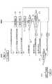
【図1】本発明の第1実施形態における移動体通信システムのブロック構成図である。
【図2】本発明の第1実施形態における自動再送要求での移動体通信システムの連携動作を説明するための図である。
【図3】図3(a)は、TDM方式を適用した場合のデータ送信の様子を説明するための図であり、図3(b)は、CDM方式を適用した場合のデータ送信の様子を説明するための図である。
【図4】本発明の第2実施形態における移動体通信システムのブロック構成図である。
【図5】本発明の第2実施形態における自動再送要求での移動体通信システムの連携動作を説明するための図である。
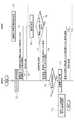
【図6】本発明の信号送信方法が適用される第3の実施形態の移動体通信システムのブロック図である。
【図7】本発明の第3の実施形態の動作を示すフローチャートである。
【図8】本発明の信号送信方法が適用される第4の実施形態の移動体通信システムのブロック図である。
【図9】本発明の第4の実施形態の動作を示すフローチャートである。
【図10】本発明の第4の実施形態の周波数チャネル番号及び該周波数チャネルの送信電力を決定する処理手順を示すフローチャートである。
【図11】本発明の第4の実施形態において、各移動局における各周波数チャネルの受信品質の一例を示す図である。
【図12】本発明の信号送信方法が適用される第5の実施形態の移動体通信システムのブロック図である。
【図13】従来の移動体通信システムのブロック構成図である。
【図14】従来の自動再送要求での移動体通信システムの連携動作を説明するための図である。
【図15】従来の自動再送要求が行われる移動体通信システムのブロック図である。
【図16】従来の移動体通信システムの動作を説明するための図である。
【符号の説明】
4…送受分波器、5…受信機、6…データ入力端、7…基地局第1アンテナ、8…基地局第2アンテナ、15…送信機、16…送受分波器、17…移動局アンテナ、100…移動体通信システム、101…基地局、102…ARQ処理器、103…送信機、111…移動局、113…ARQ処理器、118…受信品質測定器、119…メモリ[0001]
BACKGROUND OF THE INVENTION
The present invention relates to a mobile communication system, a mobile communication method, a base station, and a mobile station. More specifically, the present invention includes a mobile station and a base station having a plurality of antennas, and an automatic retransmission from the mobile station. Mobile communication system performing signal transmission / reception control including signal retransmission control by base station based on request, mobile communication method executed in mobile communication system, base station constituting mobile communication system, and mobile station About.
[0002]
In addition, the present invention relates to a signal transmission method and system in a mobile communication system, and more particularly, in a mobile communication system that transmits and receives signals while making an automatic retransmission request, a channel so as to improve reception quality at the mobile station. The present invention relates to a signal transmission method and system for transmitting a signal by changing the signal.
[0003]
Furthermore, the present invention relates to a base station that performs communication according to such a signal transmission method.
The present invention also relates to a mobile station that performs communication according to such a signal transmission method.
[0004]
[Prior art]
FIG. 13 is a block diagram of a conventional
[0005]
In the
[0006]
If no error is detected in the received data, the
[0007]
On the other hand, when an error is detected in the received data at A4, the
[0008]
15 and 16 are flowcharts for explaining the configuration and operation of a conventional mobile communication system. As shown in FIG. 15, the conventional mobile communication system includes a
[0009]
The
[0010]
The operation of the conventional mobile communication system will be described below with reference to the flowchart of FIG.
In the
[0011]
In the
[0012]
On the other hand, if an error is detected in the received signal (YES in B5), the
[0013]
[Problems to be solved by the invention]
However, in the conventional method for transmitting a high-quality signal with an automatic retransmission request in the conventional mobile communication system described with reference to FIGS. 13 and 14, since transmission is always performed using the same base station antenna, reception antenna diversity is reduced. In a simple mobile station that cannot be realized, or in a mobile station that stays in the same place for a long time, the low reception quality state due to the influence of fading or shadowing is continued, so there is a problem that the retransmission request is repeated and throughput decreases. .
[0014]
In addition, as described with reference to FIGS. 15 and 16, in the conventional mobile communication system, the base station transmits only the predetermined frequency channel for signal transmission addressed to the mobile station. For simple mobile stations that cannot realize antenna diversity, or mobile stations that have been in the same place for a long time, there is a problem that the reception quality remains low due to fading or shadowing, and retransmission requests are repeated, resulting in a decrease in throughput. .
[0015]
Accordingly, an object of the present invention is to improve throughput by reducing repetition of retransmission requests from mobile stations.
[0016]
[Means for Solving the Problems]
In order to solve the above-mentioned problem, a mobile communication system according to the present invention comprises a mobile station and a base station, and performs mobile signal transmission / reception while making an automatic retransmission request. In the system, the mobile station uses reception quality measurement means for measuring reception quality of a radio signal transmitted from a base station, and use of radio resources that conform to the reception quality based on the measured reception quality of the radio signal. Request transmitting means for transmitting a radio resource use request for requesting to the base station, the base station receiving request for the radio resource use request, and a radio resource requested by the radio resource use request Signal transmitting means for transmitting a signal addressed to the mobile station including a signal requested to be retransmitted by the automatic retransmission request, and the signal transmitting means includes:This is the number of mobile stations that made retransmission requests for the same multicast data Signals are transmitted using radio resources in descending order of the number of retransmission requests.
[0033]
The mobile communication method according to
[0065]
Furthermore, the present invention provides the claims.5 In a mobile communication system that is composed of a mobile station and a base station and transmits and receives signals while making an automatic retransmission request,
The mobile station comprises reception quality measuring means for measuring the reception quality of a radio signal transmitted from a base station, and reception quality notifying means for notifying the base station of the measured reception quality of the radio signal. The station comprises a transmission means for transmitting the signal requested for retransmission from the mobile station based on the reception quality notified from the mobile station so that the mobile station satisfies the required reception quality, the reception quality notification means, When the retransmission request of the received signal is required, the retransmission request is notified to the base station together with the measured reception quality of the radio signal, and the transmission means includes:This is the number of mobile stations that made retransmission requests for the same multicast data A signal is transmitted using radio resources in descending order of the number of retransmission requests.
The present invention also includes claims.6 As shown in FIG. 1, in a mobile communication system that is composed of a mobile station and a base station and transmits and receives signals while making an automatic retransmission request, the mobile station determines the reception quality of a radio signal transmitted from the base station. A reception quality measuring means for measuring, and a reception quality notifying means for notifying the base station of the reception quality of the measured radio signal, wherein the base station sends a signal requested to be retransmitted from the mobile station from the mobile station. Transmitting means for transmitting the mobile station so as to satisfy the required reception quality based on the notified reception quality, the reception quality notification means, when notifying the arrival confirmation of the received signal to the base station, Notifying the base station of the measured reception quality of the plurality or single radio channel, the transmission means,This is the number of mobile stations that made retransmission requests for the same multicast data A signal is transmitted using radio resources in descending order of the number of retransmission requests.
[0066]
A mobile communication system according to
[0069]
Hereinafter, the detailed description and the accompanying drawings will be exemplified so that the present invention can be more fully understood, but the present invention is not limited to these descriptions.
Furthermore, the suitable range of this invention becomes clear from the detailed description shown below. However, this detailed description is merely a preferred example of the embodiment of the present invention, and based on the technical contents that are clearly derived from the detailed description, it does not depart from the spirit and purpose of the present invention. It is possible to adopt various variations and modifications as appropriate.
[0071]
Further claims5 Or6 In the mobile communication system shown in FIG. 1, the transmission means transmits signals using radio resources in descending order of the number of retransmission requests from the mobile station.
[0073]
DETAILED DESCRIPTION OF THE INVENTION
Hereinafter, embodiments of the present invention will be described in detail with reference to the accompanying drawings.
[First Embodiment]
A first embodiment of the present invention will be described with reference to FIGS. Here, a case where two base station antennas are used will be described. However, the present invention can be realized using any number of base station antennas.
[0074]
First, the configuration of the mobile communication system will be outlined. As shown in FIG. 1, the
The
[0075]
The
[0076]
In the present embodiment, the following description will be continued when reception power is used as reception quality. However, as specified in
[0077]
Next, the operation of the mobile communication system will be described with reference to FIG.
In the
[0078]
The
[0079]
In the
[0080]
Next, the output of the
[0081]
In the
[0082]
Then, as shown in FIG. 3A, the output of the
[0083]
In addition, although the said description is a case where a TDM (Time Division Multiple) system is applied, it is also possible to apply a CDM (Code Division Multiple) system. As shown in FIG. 3B, after the signal for reception quality measurement is spread with a spreading code uniquely corresponding to each antenna, the signal is transmitted from the corresponding antenna. The mobile station can use the received power obtained by receiving the signal and despreading with a spreading code uniquely corresponding to the antenna, or a correlation value or the like as the reception quality.
[0084]
Hereinafter, description will be given returning to the case where the TDM method is applied.
In the
[0085]
When the
[0086]
On the other hand, if an error is detected in the received data in
[0087]
In addition, by storing the antenna number requested by the
[0088]
According to the first embodiment described above, based on the reception quality of the signal measured by the
[0089]
In the above description, the reception quality measurement signal is transmitted before data transmission. However, as described in
[0090]
The present embodiment is also applicable to a mobile station that functions as a relay station instead of a base station assuming a multi-hop connection. In this case, the
[0091]
[Second Embodiment]
The configuration of the second embodiment of the present invention will be described with reference to FIG.
In this embodiment, it is a case of multicast transmission in which the same data (referred to as multicast data in this embodiment) is transmitted from a base station to a plurality of mobile stations, and notification of a retransmission request when an error is detected It will be described as an automatic retransmission request only performed. Also, there are a plurality of mobile stations that receive multicast data. Hereinafter, the operation of one of the mobile stations will be described. Of course, other mobile stations that are omitted multicast targets perform the same operation.
[0092]
In the
[0093]
In this embodiment, it is assumed that the
[0094]
In one
[0095]
If there is no error in the received multicast data due to the error detection in the CRC, the
[0096]
In the
[0097]
Next, a cooperative operation between the
[0098]
The
[0099]
Next, in the
[0100]
In receiving the first retransmission multicast data, mobile station A to mobile station C notify the
[0101]
In the
[0102]
In receiving the second retransmission multicast data, since the mobile station B and the mobile station C did not detect an error, nothing is transmitted to the
[0103]
Then, the
[0104]
Since the mobile station A did not detect an error in the reception of the third retransmission multicast data, the mobile station A does not transmit anything to the
By the operation as described above, it is possible to realize transmission of a high quality signal with the automatic retransmission request of the present invention at the time of multicast data transmission.
[0105]
According to the second embodiment, retransmission multicast data is transmitted from the
[0106]
In the first and second embodiments, an example in which a mobile station transmits an antenna use request to use one of a plurality of base station antennas is shown. However, a large number of base station antennas are provided. In such a case, the mobile station may be configured to transmit an antenna use request specifying two or more base station antennas with good reception quality as antennas to request use.
[0107]
By the way, the present invention can be said to be a diversity method using a plurality of antennas in one base station, but site diversity is known as a diversity method using one antenna in a plurality of base stations.
[0108]
In this site diversity, there is no correlation with shadowing (short-term median fluctuation), so there is a large diversity gain effect. However, there is no correlation with fading (instantaneous fluctuation), so the diversity gain is large. However, it is difficult to realize diversity gain because control signals are transmitted between multiple base stations with respect to the control time, and it is difficult to realize diversity gain. In this case, the efficiency is poor.
[0109]
If the present invention is used in combination with the above-described site diversity, the effect of increasing the diversity gain by using a plurality of base stations can be obtained for shadowing. Moreover, since the control time can be shortened as much as possible due to the feature of the present invention in which a plurality of antennas are used in one base station, a large diversity gain can be realized against fading. Thus, the maximum diversity gain can be obtained by applying site diversity to the present invention.
[0110]
Note that this embodiment is applicable to a mobile station that functions as a relay station instead of a base station, assuming a multi-hop connection. In this case, the
[0111]
[Third Embodiment]
A third embodiment of the present invention will be described with reference to FIGS. In this embodiment, a case where the base station transmits a signal to the mobile station using the multiband transmission method will be described as an example.
[0112]
FIG. 6 is a configuration diagram of the mobile communication system in the present embodiment, which includes a
[0113]
Next, the operation will be described with reference to the flowchart of FIG.
In the
[0114]
In addition, when the compensation of the frequency channel number of the frequency band used for signal transmission is known in advance, the notification of the frequency channel number of the frequency band can be omitted.
[0115]
On the other hand, in the
[0116]
As described above, the reception
[0117]
In such a
[0118]
On the other hand, when an error is detected in the signal received at T6 (YES at T6), the
[0119]
When a retransmission request is input to the
[0120]
Thereafter, the
[0121]
Also, when the frequency band station frequency channel number candidate used for retransmission is known in advance, the notification of the frequency channel number of the frequency band used for retransmission is omitted, and the mobile station selects the frequency channel number candidate of the frequency band. The retransmission signal is received with the frequency channel number of the frequency band having the highest reception quality.
[0122]
As described above, in this embodiment, the case where the multiband transmission method is used as an example of the transmission method between the
[0123]
As described above, according to the third embodiment of the present invention, the
[0124]
Note that this embodiment is applicable to a mobile station that functions as a relay station instead of a base station, assuming a multi-hop connection. In this case, the
[0125]
[Fourth Embodiment]
Next, a fourth embodiment of the present invention will be described with reference to FIGS. In this embodiment, the case where the base station transmits a multicast signal to each mobile station by the FDM transmission method will be described as an example.
[0126]
FIG. 8 is a configuration diagram of a mobile communication system according to the fourth embodiment, and includes a
[0127]
Next, the operation of the mobile communication system in the present embodiment will be described with reference to the flowchart of FIG. Here, there are a plurality of mobile stations in a group that receives one multicast signal. Hereinafter, only one mobile station in the group will be described. The other mobile stations belonging to the group perform the same operation as the mobile station described below.
[0128]
In the
In addition, when the candidate of the frequency channel number used for transmission of the multicast signal is known in advance, the notification of the frequency channel number can be omitted.
[0129]
On the other hand, in the
[0130]
As described above, the reception
[0131]
In the present embodiment, the following description is continued for the case where C / I is used as the reception quality. However, the received power, C / (I + N), S / (I + N), C / N, or S / N, or The error rate, the likelihood obtained at the time of error decoding, the base station transmission power value, the amount of increase or attenuation of the base station transmission power, or a combination thereof may be used as the reception quality. “C” in C / (I + N) represents carrier power, and “S” in S / (I + N) represents signal power. In the C / (I + N) and S / (I + N), “I” represents interference power, and “N” represents noise power.
Thus, in the present invention, any signal can be used for reception quality measurement as long as the signal is transmitted from the
[0132]
In the
[0133]
Then, the
[0134]
On the other hand, when an error is detected in the received multicast signal (YES in T26), the
[0135]
When a retransmission request is input to the
[0136]
Then, the multicast signal stored for retransmission in the
[0137]
Each mobile station that receives the retransmission multicast signal receives the retransmission multicast signal on the channel of the frequency channel number that provides the maximum reception quality in the mobile station from the broadcast frequency numbers. In addition, when a plurality of or single frequency channel number candidates to be used for retransmission are known in advance, the notification of the frequency channel number for retransmitting the multicast signal is omitted, and each mobile station can select from the frequency channel number candidates. A retransmission multicast signal is received with the frequency channel number that provides the maximum reception quality.
[0138]
The
[0139]
As described above, in the fourth embodiment, the case where the FDM transmission method is used as an example of the transmission method between the
[0140]
As described above, according to the fourth embodiment of the present invention, the
[0141]
Next, an example of a procedure for determining the frequency channel number and transmission power of a radio channel will be described using FIG. 10 assuming the mobile communication system in the present embodiment.
[0142]
The determination of the frequency channel number and the transmission power is calculated by the
[0143]
Hereinafter, for convenience of explanation, a case where up to three frequency channels (f = 0 to 2) can be used is taken as an example. Therefore, since any three frequency channels can be selected, there are seven (c = 0 to 6) frequency combinations. In addition, the reception quality of each frequency channel in each mobile station will be described assuming that the
[0144]
FIG. 11 is a graph showing an example where the
[0145]
Similarly, in the
[0146]
Here, as a premise for explaining the flowchart of FIG. 10, a correspondence relationship between a combination of frequency channels f assumed to be used for retransmission and c representing a classification of the combination is shown below.
c = 0: f = 0 (using the first frequency channel)
c = 1: f = 1 (using the second frequency channel)
c = 2: f = 2 (using the third frequency channel)
c = 3: f = 0, 1 (using first and second frequency channels)
c = 4: f = 1, 2 (using second and third frequency channels)
c = 5: f = 0, 2 (using first and third frequency channels)
c = 6: f = 0, 1, 2 (using the first, second and third frequency channels)
In FIG. 10, first, assuming that c = 0, that is, only the first frequency channel is used, the mobile station is set to mobile station 1 (i = 0) (T41), and the calculation of (T42) is executed. . At T2, MAX {q (i, f)} is calculated. Here, q (i, f) represents the reception quality of the frequency channel f at the mobile station i. MAX {q (i, f)} indicates the maximum q (i, f) among all frequency channels f that can be taken by the frequency channel combination classification c in the mobile station i. In this example, when i = 0, the maximum reception quality when c = 0 is when f = 0.
Q (0,0) = q (0,0) = 0dB
(See (1) in FIG. 11).
[0147]
When q (0, 0) is obtained in this way, the process proceeds to the next (T43), and i is incremented by “1” (i = 1, mobile station 2). In this (T43), since modulo operation is performed, it is incremented until the remainder obtained by dividing (i + I) by M (the total number of mobile stations that have notified the request) becomes zero. Therefore, here, since 1 mod 3 (= M) and i ≠ 0, the determination in T44 is NO and the processing from T42 is executed again. That is, the processes of T42 to T43 are repeatedly executed until i and M are equal (until i = 3).
[0148]
Therefore, since NO is obtained in the determination of T44, the process returns to T42, and MAX {q (i, f)} is calculated for mobile station 2 (i = 1), and the following results are obtained. (See (2) in FIG. 11).
Q (1,0) = MAX {q (1,0)} = − 20 dB
Further, i = 2 (mobile station 3) is calculated in the same manner as the above procedure,
Q (2,0) = MAX {q (2,0)} =-15 dB
(See (3) in FIG. 11).
[0149]
In this way, when T42 is executed (c = 0) for all mobile stations (i = 0 to 2), i = 0 is determined in T44 (YES in T44), and the process proceeds to the next T45.
At T45, P (c) = Σ {Qreq−MIN (Q (i, f))} is calculated as follows. Here, Qreq represents required reception quality, and P (c) represents transmission power from the base station when the frequency channel combination classification is c.
When c = 0, it is calculated as follows.
[0150]
In this way, when calculation of P (c) in the case of c = 0 is completed, the process proceeds to the next T46, and the frequency channel combination classification c is incremented. Here, since 1 mod 6 (Nc) and c ≠ 0, the determination result in (T47) is NO, and the processing from (T42) is executed again. That is, the processes of T42 to T46 are repeatedly performed until c and Nc are equal (in this example, until c = 6).
[0151]
Hereinafter, with respect to c = 1 to c = 6, the results of calculating Q (i, f) and P (c) in the same manner as described above are shown.
[0152]
Since the true value of (0 dB) is “1” and the true value of (+15 dB) is “≈31.6”,
x = 1 + 31.6 = 32.6
10 10 logx = 10 log 32.6≈ + 15.1 dB.
[0153]
Since the true value of (0 dB) is “1” and the true value of (+1 dB) is “≈1.26”,
x = 1 + 1.26 = 2.26
10 10 logx = 10 log 2.26≈ + 3.5 dB.
[0154]
Since the true value of (0 dB) is “1” and the true value of (+10 dB) is “10”,
x = 1 + 10 = 11
10 10logx = 10log11≈10.4dB.
[0155]
Since the true value of (0dB) is “1”,
x = 1 + 1 + 1 = 3
10 10logx = 10log3≈ + 4.8dB.
As described above, when P (0) to P (6) are calculated, the process proceeds to T48, and MIN {P (c)} is calculated.
The calculation method of MIN {P (c)} is shown below.
MIN {P (c)}
= MIN {P (0), P (1), P (2), P (3), P (4), P (5), P (6)}
= MIN {+20 dB, +20 dB, +15 dB, +15.1 dB, +35 dB, +10.4 dB, +4.8 dB,}
Therefore, by calculating T48,
MIN {P (c)} = P (4) = + 3.5 dB is obtained.
[0156]
As a result, the state of the combination of frequency channels of c = 4 is finally selected, the second frequency channel is set to transmission power +1 dB, the third frequency channel is set to
[0157]
According to the processing described above, it is possible to obtain the frequency channel number and transmission power that minimize the transmission power from the base station while satisfying the required reception quality at the mobile station.
[0158]
Note that this embodiment is applicable to a mobile station that functions as a relay station instead of a base station, assuming a multi-hop connection. In this case, the
[0159]
[Fifth Embodiment]
Finally, a fifth embodiment of the present invention will be described with reference to the configuration diagram of FIG. In the present embodiment, a configuration in which a base station inputs a multicast signal in units of packets and transmits the packet by a multi-carrier transmission scheme is used as a NACK-based automatic retransmission request in which notification of arrival confirmation is not performed but only notification of retransmission request is performed. And In addition, by using a spreading code as the retransmission request, a combination of the fact that retransmission is requested even when the retransmission request signal collides at the base station and a method for detecting the number of the packet for which retransmission has been requested. The case will be described as an example.
[0160]
A method capable of detecting that a retransmission is requested even if a retransmission request collision occurs is disclosed in an international application (PCT / JP01 / 02923).
FIG. 12 is a configuration diagram of a mobile communication system according to the tree embodiment, and includes a
[0161]
The
[0162]
On the other hand, in the
[0163]
In such a
[0164]
When an error is detected in the received packet, the
[0165]
Spreading code number = (packet number) + (subcarrier number) × 16
For example, when the retransmission packet number is “8” and the subcarrier number for requesting transmission of the retransmission packet is “3”, 8 + 3 × 16 = 56, so that the mobile station uses the 56th spreading code as a retransmission request signal. By transmitting, even when a retransmission request signal collision occurs in the
[0166]
For the spreading code transmitted by the
[0167]
As described above, according to the configuration and operation of the mobile communication system in the present embodiment, the reception quality at the mobile station can be improved.
[0168]
Further, according to the mobile communication system in the present embodiment, the
[0169]
Note that this embodiment is applicable to a mobile station that functions as a relay station instead of a base station, assuming a multi-hop connection. In this case, the
[0170]
In the above embodiments, the reception quality measuring functions of the reception
[0171]
The transmission functions of the
[0172]
Of course, the embodiments of the present invention described above may take various modifications. Such modifications are considered so as not to depart from the spirit and purpose of the present invention, and the following claims are technical contents intended to include all the modifications described above.
[0173]
【The invention's effect】
According to the present invention, based on the reception quality of a signal measured by a mobile station, a signal addressed to the mobile station is transmitted from at least one antenna of the base station whose reception quality is relatively good. Is done. Therefore, the signal reception quality at the mobile station is improved. Thereby, it is possible to prevent the retransmission request from the mobile station from being repeatedly performed and to improve the throughput.
[Brief description of the drawings]
FIG. 1 is a block configuration diagram of a mobile communication system in a first embodiment of the present invention.
FIG. 2 is a diagram for explaining a cooperative operation of a mobile communication system in response to an automatic retransmission request in the first embodiment of the present invention.
FIG. 3A is a diagram for explaining the state of data transmission when the TDM method is applied, and FIG. 3B is the state of data transmission when the CDM method is applied. It is a figure for demonstrating.
FIG. 4 is a block configuration diagram of a mobile communication system in a second embodiment of the present invention.
FIG. 5 is a diagram for explaining a cooperative operation of a mobile communication system in response to an automatic retransmission request in the second embodiment of the present invention.
FIG. 6 is a block diagram of a mobile communication system according to a third embodiment to which the signal transmission method of the present invention is applied.
FIG. 7 is a flowchart showing the operation of the third exemplary embodiment of the present invention.
FIG. 8 is a block diagram of a mobile communication system according to a fourth embodiment to which the signal transmission method of the present invention is applied.
FIG. 9 is a flowchart showing the operation of the fourth exemplary embodiment of the present invention.
FIG. 10 is a flowchart showing a processing procedure for determining a frequency channel number and transmission power of the frequency channel according to the fourth embodiment of the present invention.
FIG. 11 is a diagram illustrating an example of reception quality of each frequency channel in each mobile station in the fourth embodiment of the present invention.
FIG. 12 is a block diagram of a mobile communication system according to a fifth embodiment to which the signal transmission method of the present invention is applied.
FIG. 13 is a block diagram of a conventional mobile communication system.
FIG. 14 is a diagram for explaining a cooperative operation of a mobile communication system in a conventional automatic retransmission request.
FIG. 15 is a block diagram of a mobile communication system in which a conventional automatic retransmission request is performed.
FIG. 16 is a diagram for explaining the operation of a conventional mobile communication system.
[Explanation of symbols]
DESCRIPTION OF
Claims (13)
Translated fromJapanese前記移動局は、
基地局から送信される無線信号の受信品質を測定する受信品質測定手段と、
該測定された無線信号の受信品質に基づいて、受信品質に適合する無線リソースの使用を要求する無線リソース使用要求を前記基地局に送信する要求送信手段とを備え、
前記基地局は、
前記無線リソース使用要求を受信する要求受信手段と、
前記無線リソース使用要求により要求された無線リソースを用いて、前記自動再送要求により再送を要求された信号を含む前記移動局宛の信号を送信する信号送信手段とを備え、
前記信号送信手段は、同一のマルチキャストデータに対して再送要求を行った移動機の数である再送要求数が多い順に無線リソースを使用して信号を送信することを特徴とする移動体通信システム。In a mobile communication system that is composed of a mobile station and a base station and transmits and receives signals while making an automatic retransmission request,
The mobile station
Reception quality measuring means for measuring the reception quality of the radio signal transmitted from the base station;
Request transmission means for transmitting to the base station a radio resource use request for requesting use of radio resources matching the reception quality based on the measured reception quality of the radio signal;
The base station
Request receiving means for receiving the radio resource use request;
Signal transmitting means for transmitting a signal addressed to the mobile station including a signal requested to be retransmitted by the automatic retransmission request, using a radio resource requested by the radio resource use request;
The mobile communication system characterized in that the signal transmission means transmits signals using radio resources in descending order ofthe number of retransmission requests,which is the number of mobile stations that have requested retransmission for thesame multicast data .
前記移動局にて、前記基地局の複数のアンテナから送信された信号の受信品質を測定する品質測定工程と、
前記移動局にて、前記測定により得られた各アンテナからの信号の受信品質に基づいて、前記複数のアンテナの内、少なくとも1つのアンテナからのマルチキャスト信号の送信を要求する旨のアンテナ使用要求を前記基地局に送信する要求送信工程と、
前記基地局にて、前記複数のアンテナの内、少なくとも1つのアンテナからのマルチキャスト信号の送信を要求する旨のアンテナ使用要求を受信する要求受信工程と、
前記基地局にて、前記アンテナ使用要求により要求されたアンテナから、前記自動再送要求により再送を要求されたマルチキャスト信号を含む前記複数の移動局宛てのマルチキャスト信号を送信するマルチキャスト信号送信工程と、を備え、
前記マルチキャスト信号送信工程では、複数の移動局からのアンテナ使用要求が複数アンテナにわたって存在する場合、前記基地局は、同一のマルチキャストデータに対して再送要求を行った移動機の数である再送要求数が多い順にアンテナを使用してマルチキャスト信号を送信することを特徴とする移動体通信方法。Signal transmission / reception executed by a mobile communication system including a plurality of mobile stations and a base station having a plurality of antennas, and includes signal retransmission control by the base station based on an automatic retransmission request from the mobile station A mobile communication method for performing control,
In the mobile station, a quality measurement step of measuring reception quality of signals transmitted from a plurality of antennas of the base station;
In the mobile station, an antenna use request for requesting transmission of a multicast signal from at least one of the plurality of antennas based on the reception quality of the signal from each antenna obtained by the measurement. A request transmission step of transmitting to the base station;
A request receiving step of receiving an antenna use request for requesting transmission of a multicast signal from at least one of the plurality of antennas in the base station;
A multicast signal transmitting step of transmitting, from the antenna requested by the antenna use request, a multicast signal addressed to theplurality of mobile stations including the multicast signal requested to be retransmitted by the automatic retransmission request at the base station; Prepared,
In the multicast signal transmission step, when there are antenna usage requests from a plurality of mobile stations over a plurality of antennas, the base station determinesthe number of retransmission requeststhat is the number of mobile stations thathave made a retransmission request for thesame multicast data. A mobile communication method characterized in that a multicast signal is transmitted using an antenna in order of increasing number.
前記移動局は、前記基地局の少なくとも1つのアンテナから送信される、同期信号、報知情報の信号、移動局への個別の信号、マルチキャスト信号、又はこれらの内2つ以上の組合せを用いることにより、前記受信品質を測定することを特徴とする請求項2に記載の移動体通信方法。In the quality measurement step,
The mobile station uses a synchronization signal, a broadcast information signal, an individual signal to the mobile station, a multicast signal, or a combination of two or more of them transmitted from at least one antenna of the base station. 3. The mobile communication method according to claim 2, wherein the reception quality is measured.
前記移動局は、基地局から送信される無線信号の受信品質を測定する受信品質測定手段と、
該測定された無線信号の受信品質を基地局に通知する受信品質通知手段とを備え、
前記基地局は、前記移動局から再送要求された信号を該移動局から通知された受信品質に基づいて該移動局が所要の受信品質を満たすように送信する送信手段を備え、
前記受信品質通知手段は、受信した信号の再送要求が必要なときに、前記測定された無線信号の受信品質と共に、前記再送要求を前記基地局に対して通知し、
前記送信手段は、同一のマルチキャストデータに対して再送要求を行った移動機の数である再送要求数が多い順に無線リソースを使用して信号を送信することを特徴とする移動体通信システム。In a mobile communication system that is composed of a mobile station and a base station and transmits and receives signals while making an automatic retransmission request,
The mobile station has reception quality measuring means for measuring reception quality of a radio signal transmitted from a base station,
Reception quality notification means for notifying the base station of the reception quality of the measured radio signal,
The base station comprises transmission means for transmitting a signal requested to be retransmitted from the mobile station so that the mobile station satisfies a required reception quality based on the reception quality notified from the mobile station,
The reception quality notifying means notifies the base station of the retransmission request together with the measured reception quality of the radio signal when a retransmission request of the received signal is required,
The mobile communication system characterized in that the transmitting means transmits signals using radio resources in descending order ofthe number of retransmission requests,which is the number of mobile stations that have requested retransmission for thesame multicast data .
前記移動局は、基地局から送信される無線信号の受信品質を測定する受信品質測定手段と、
該測定された無線信号の受信品質を基地局に通知する受信品質通知手段とを備え、
前記基地局は、前記移動局から再送要求された信号を該移動局から通知された受信品質に基づいて該移動局が所要の受信品質を満たすように送信する送信手段を備え、
前記受信品質通知手段は、受信した信号の到達確認を前記基地局に通知する際に、前記測定した複数又は単一の無線チャネルの受信品質を該基地局に通知し、
前記送信手段は、同一のマルチキャストデータに対して再送要求を行った移動機の数である再送要求数が多い順に無線リソースを使用して信号を送信することを特徴とする移動体通信システム。In a mobile communication system that is composed of a mobile station and a base station and transmits and receives signals while making an automatic retransmission request,
The mobile station has reception quality measuring means for measuring reception quality of a radio signal transmitted from a base station,
Reception quality notification means for notifying the base station of the reception quality of the measured radio signal,
The base station comprises transmission means for transmitting a signal requested to be retransmitted from the mobile station so that the mobile station satisfies a required reception quality based on the reception quality notified from the mobile station,
The reception quality notification means, when notifying the base station of the arrival confirmation of the received signal, notifies the base station the reception quality of the measured multiple or single radio channel,
The mobile communication system characterized in that the transmitting means transmits signals using radio resources in descending order ofthe number of retransmission requests,which is the number of mobile stations that have requested retransmission for thesame multicast data .
前記受信品質通知手段は、複数又は単一の無線チャネルの番号と、該無線チャネルの受信品質又は所定範囲にある受信品質のチャネル番号のみを前記測定した複数又は単一の無線チャネルの受信品質として基地局に通知する移動体通信システム。The mobile communication system according to claim5 or6 ,
The reception quality notification means is configured to measure only the number of a plurality of or single radio channels and the reception quality of the radio channels or the channel number of the reception quality within a predetermined range as the measured reception quality of the plurality of or single radio channels. A mobile communication system for notifying a base station.
前記受信品質通知手段は、前記移動局での受信品質が最大となる受信品質を含む所要受信品質を得た複数又は単一の無線チャネルの番号を、該得た受信品質と共に前記基地局に通知する移動体通信システム。The mobile communication system according to claim5 or6 ,
The reception quality notifying means notifies the base station together with the obtained reception quality, the number of a plurality of or a single radio channel that has obtained the required reception quality including the reception quality that maximizes the reception quality at the mobile station. Mobile communication system.
前記基地局は、前記移動局からの通知に基づいて該移動局が所要受信品質を満たす無線チャネルを求める無線チャネル決定手段と、
該無線チャネル決定手段にて求められた無線チャネルを用いて、該移動局から再送要求された信号を送信する送信手段とを備える移動体通信システム。The mobile communication system according to claim5 , wherein
The base station, based on a notification from the mobile station, a radio channel determination means for obtaining a radio channel that satisfies the required reception quality of the mobile station;
A mobile communication system comprising: transmission means for transmitting a signal requested to be retransmitted from the mobile station using the radio channel obtained by the radio channel determination means.
前記送信手段は、前記移動局から再送要求された信号を前記求めた無線チャネルで送信した後も、該移動局宛の信号に対しては前記求めた無線チャネルを用いて送信する移動体通信システム。The mobile communication system according to claim9 , wherein
The transmission means transmits the signal requested to be retransmitted from the mobile station through the obtained radio channel and transmits the signal addressed to the mobile station using the obtained radio channel. .
前記基地局は、前記移動局からの通知に基づいて、該移動局での所要受信品質を満足し、かつ該基地局からの送信電力が所定値となるように送信する無線チャネルの番号を決定する第1の無線チャネル番号決定手段、及び該無線チャネルの送信電力を決定する第1の無線チャネル送信電力決定手段とを備える移動体通信システムにおける移動体通信システム。The mobile communication system according to claim9 , wherein
Based on the notification from the mobile station, the base station determines a radio channel number to be transmitted so that the required reception quality at the mobile station is satisfied and the transmission power from the base station becomes a predetermined value. A mobile communication system in a mobile communication system, comprising: a first radio channel number determining unit that performs determination; and a first radio channel transmission power determination unit that determines transmission power of the radio channel.
前記基地局は、複数の移動局に同一のマルチキャスト信号を送信する場合に、各移動局からの通知に基づいて、各移動局での所要受信品質を満足し、かつ該基地局からの送信電力が所定値となるように該マルチキャスト信号を送信する複数又は単一の無線チャネルの番号を決定する第2の無線チャネル番号決定手段、及び該無線チャネルの送信電力を決定する第2の無線チャネル送信電力決定手段とを備える移動体通信システム。The mobile communication system according to claim11 , wherein
When transmitting the same multicast signal to a plurality of mobile stations, the base station satisfies the required reception quality at each mobile station based on the notification from each mobile station, and the transmission power from the base station Second radio channel number determining means for determining the number of a plurality of or a single radio channel for transmitting the multicast signal so as to be a predetermined value, and second radio channel transmission for determining the transmission power of the radio channel A mobile communication system comprising power determining means.
前記基地局は、複数の移動局に同一のマルチキャスト信号を送信する場合に、各移動局から通知された所定範囲にある受信品質のチャネル番号の内、移動局からの再送要求が多いとみなし得る無線チャネルの番号を求める第3の無線チャネル番号決定手段を備える移動体通信システム。The mobile communication system according to claim12 ,
When the base station transmits the same multicast signal to a plurality of mobile stations, it can be considered that there are many retransmission requests from the mobile station among the channel numbers of the reception quality in the predetermined range notified from each mobile station. A mobile communication system comprising third wireless channel number determination means for obtaining a wireless channel number.
Priority Applications (1)
| Application Number | Priority Date | Filing Date | Title |
|---|---|---|---|
| JP2002173353AJP4271903B2 (en) | 2001-06-13 | 2002-06-13 | Mobile communication system and mobile communication method |
Applications Claiming Priority (5)
| Application Number | Priority Date | Filing Date | Title |
|---|---|---|---|
| JP2001178999 | 2001-06-13 | ||
| JP2001-178999 | 2001-06-13 | ||
| JP2001-186910 | 2001-06-20 | ||
| JP2001186910 | 2001-06-20 | ||
| JP2002173353AJP4271903B2 (en) | 2001-06-13 | 2002-06-13 | Mobile communication system and mobile communication method |
Publications (2)
| Publication Number | Publication Date |
|---|---|
| JP2003078480A JP2003078480A (en) | 2003-03-14 |
| JP4271903B2true JP4271903B2 (en) | 2009-06-03 |
Family
ID=27346928
Family Applications (1)
| Application Number | Title | Priority Date | Filing Date |
|---|---|---|---|
| JP2002173353AExpired - Fee RelatedJP4271903B2 (en) | 2001-06-13 | 2002-06-13 | Mobile communication system and mobile communication method |
Country Status (1)
| Country | Link |
|---|---|
| JP (1) | JP4271903B2 (en) |
Families Citing this family (41)
| Publication number | Priority date | Publication date | Assignee | Title |
|---|---|---|---|---|
| CA2518590C (en)* | 2003-06-18 | 2010-08-10 | Nippon Telegraph And Telephone Corporation | Wireless packet communication method |
| EP1615365A4 (en) | 2003-06-30 | 2011-05-11 | Fujitsu Ltd | MULTI-INPUT AND MULTI-OUTPUT TRANSMISSION SYSTEM |
| JPWO2005008931A1 (en) | 2003-07-16 | 2006-09-28 | 日本電気株式会社 | Transmitter, receiver, wireless communication system |
| JP4275667B2 (en) | 2003-11-11 | 2009-06-10 | 三菱電機株式会社 | Communication method, communication system, and terminal |
| JP4510870B2 (en)* | 2003-11-21 | 2010-07-28 | パナソニック株式会社 | Wireless communication method and wireless communication device |
| EP1684454A4 (en) | 2003-11-21 | 2013-07-03 | Panasonic Corp | METHOD, DEVICE, TRANSMISSION APPARATUS AND MULTI-ANTENNA COMMUNICATION SYSTEM |
| KR100754660B1 (en) | 2004-06-19 | 2007-09-03 | 삼성전자주식회사 | Adaptive Modulation / Coded Channel Assignment System and Method in Communication Systems |
| JP4539231B2 (en)* | 2004-08-24 | 2010-09-08 | Kddi株式会社 | Communication method and base station using automatic retransmission control in multi-hop communication |
| WO2006043773A2 (en) | 2004-10-18 | 2006-04-27 | Lg Electronics Inc. | A method of transmitting feedback information in an orthogononal frequency division multiplexing (ofdm)/ofdm access (ofdma) mobile communication system |
| KR100932487B1 (en)* | 2004-11-03 | 2009-12-17 | 엘지전자 주식회사 | A method for transmitting feedback information for a multiple input / output system in a broadband wireless access system |
| US7564831B2 (en) | 2004-12-27 | 2009-07-21 | Lg Electronics, Inc. | Method of transmitting feedback information using an extended subheader |
| CN1832390A (en)* | 2005-03-07 | 2006-09-13 | 松下电器产业株式会社 | A retransmission method based on reliability estimation for multi-antenna adaptive transmission |
| CN101147417B (en) | 2005-03-24 | 2010-12-15 | 日本电气株式会社 | Mobile terminal of CDMA system, mobile communication method of cdma system, and communication quality estimating method |
| CN1838583A (en)* | 2005-03-25 | 2006-09-27 | 松下电器产业株式会社 | Method and device for performing data retransmission in multiple-input multiple-output communication system |
| JP4564399B2 (en)* | 2005-04-28 | 2010-10-20 | 日本放送協会 | Wireless terminal device and wireless communication system |
| KR100912784B1 (en) | 2006-01-05 | 2009-08-18 | 엘지전자 주식회사 | Data transmission method and data retransmission method |
| KR101211807B1 (en) | 2006-01-05 | 2012-12-12 | 엘지전자 주식회사 | Method for managing synchronization state for mobile terminal in mobile communication system |
| US7881724B2 (en) | 2006-01-05 | 2011-02-01 | Lg Electronics Inc. | Allocating radio resources in mobile communications system |
| EP1980062A4 (en) | 2006-01-05 | 2011-03-30 | Lg Electronics Inc | DATA TRANSMISSION IN A MOBILE COMMUNICATION SYSTEM |
| WO2007078171A2 (en) | 2006-01-05 | 2007-07-12 | Lg Electronics Inc. | Method of transmitting feedback information in a wireless communication system |
| BRPI0706841A8 (en) | 2006-01-05 | 2018-04-17 | Lg Electronics Inc | data transmission in one system and mobile communication |
| KR101265628B1 (en) | 2006-01-05 | 2013-05-22 | 엘지전자 주식회사 | method for scheduling radio resourse in the mobile communication system |
| KR101187076B1 (en) | 2006-01-05 | 2012-09-27 | 엘지전자 주식회사 | Method for transmitting signals in the moblie communication system |
| KR101216751B1 (en) | 2006-02-07 | 2012-12-28 | 엘지전자 주식회사 | Method for avoiding collision using identifier in mobile network |
| KR101358469B1 (en) | 2006-02-07 | 2014-02-06 | 엘지전자 주식회사 | Method for selection and signaling of downlink and uplink bandwidth in wireless networks |
| JP4684124B2 (en) | 2006-02-16 | 2011-05-18 | 富士通株式会社 | Mobile station apparatus and transmission power control method in the same |
| KR101387475B1 (en) | 2006-03-22 | 2014-04-22 | 엘지전자 주식회사 | method of processing data in mobile communication system having a plurality of network entities |
| EP2030359B1 (en) | 2006-06-21 | 2017-12-20 | LG Electronics Inc. -1- | Method of supporting data retransmission in a mobile communication system |
| WO2007148935A1 (en) | 2006-06-21 | 2007-12-27 | Lg Electronics Inc. | Method of transmitting and receiving radio access information using a message separation in a wireless mobile communications system |
| KR101369135B1 (en)* | 2006-06-21 | 2014-03-05 | 엘지전자 주식회사 | Mehtod for supproting quality of multimeida broadcast multicast service(mbms) in mobile communications system and terminal thereof |
| KR20070121513A (en) | 2006-06-21 | 2007-12-27 | 엘지전자 주식회사 | Uplink method of mobile communication system |
| KR100966074B1 (en) | 2007-02-15 | 2010-06-28 | 삼성전자주식회사 | Retransmission Device and Method in Wireless Communication System |
| US8879643B2 (en) | 2008-04-15 | 2014-11-04 | Qualcomm Incorporated | Data substitution scheme for oversampled data |
| KR101638911B1 (en)* | 2009-03-06 | 2016-07-12 | 엘지전자 주식회사 | Dual mode mobile terminal in mino wireless communication system and controlling method therefor |
| KR100932495B1 (en) | 2009-06-16 | 2009-12-17 | 엘지전자 주식회사 | Feedback Information Transmission and Reception Method in Broadband Wireless Access System |
| KR100932492B1 (en) | 2009-06-16 | 2009-12-17 | 엘지전자 주식회사 | Feedback Information Transmission and Reception Method in Broadband Wireless Access System |
| KR100932494B1 (en) | 2009-06-16 | 2009-12-17 | 엘지전자 주식회사 | Feedback Information Transmission and Reception Method in Broadband Wireless Access System |
| KR100932493B1 (en) | 2009-06-16 | 2009-12-17 | 엘지전자 주식회사 | Feedback Information Transmission and Reception Method in Broadband Wireless Access System |
| KR100932496B1 (en) | 2009-06-16 | 2009-12-17 | 엘지전자 주식회사 | Feedback Information Transmission and Reception Method in Broadband Wireless Access System |
| JP2010035207A (en)* | 2009-10-29 | 2010-02-12 | Fujitsu Ltd | Transmission equipment, receiving equipment, and retransmission equipment |
| EP3982571A1 (en)* | 2020-10-09 | 2022-04-13 | Nokia Technologies Oy | Data transmission |
- 2002
- 2002-06-13JPJP2002173353Apatent/JP4271903B2/ennot_activeExpired - Fee Related
Also Published As
| Publication number | Publication date |
|---|---|
| JP2003078480A (en) | 2003-03-14 |
Similar Documents
| Publication | Publication Date | Title |
|---|---|---|
| JP4271903B2 (en) | Mobile communication system and mobile communication method | |
| US7203508B2 (en) | Mobile communication systems, mobile communication methods, base stations, mobile stations, and signal transmission methods in the mobile communication systems | |
| US20220255707A1 (en) | Link adaptation for coverage enhancements and support of different service types | |
| US11246040B2 (en) | Communication method and system in wireless communication system using beamforming scheme | |
| US8533552B2 (en) | Apparatus and method for retransmitting request in wireless relay communication system | |
| US10972228B2 (en) | Base station device, user equipment, wireless communication system, and communication method | |
| US8320382B2 (en) | Mobile communication system, a mobile station, a base station and communication control method | |
| US8238927B2 (en) | OFDM cellular communication method, system and base station | |
| JP6508662B2 (en) | Wireless network coverage extension method, apparatus and system | |
| KR20100108514A (en) | Wireless communication base station device, wireless communication relay device, wireless communication terminal device, packet retransmission method, and wireless communication system | |
| US10778388B2 (en) | Method and apparatus for resource management in wireless communication systems | |
| JP2019514279A (en) | Wireless network node, wireless device and method implemented in them | |
| JP2005529508A (en) | Method in mobile communication system with smart antenna | |
| KR20190129388A (en) | Method and apparatus for accessing channel in wireless communication system | |
| JP2010526453A (en) | How to send control information | |
| US20220116186A1 (en) | Scheduling harq transmissions in mini-slots | |
| KR20200116303A (en) | Method and apparatus for transmission and reception of signal in communication system | |
| KR20180049748A (en) | Method and apparatus for detection of control signal in wirelss cellular communication system | |
| JP2011077822A (en) | Radio communication apparatus, radio communication system, and radio communication method in radio communication system | |
| US12132575B2 (en) | Method and device for sending HARQ-ACK codebook and method and device for receiving HARQ-ACK codebook | |
| US8321735B2 (en) | Joint channel code for data non-associated control signalling type | |
| US11489615B2 (en) | Method and device for transmitting and receiving configuration information | |
| US11082160B2 (en) | Communication apparatus, wireless communication system, and wireless communication method | |
| JP2014216819A (en) | Radio communication system and radio communication method | |
| US12401457B2 (en) | Dynamic hybrid automatic repeat request activation/deactivation in 5G and 6G radio interface |
Legal Events
| Date | Code | Title | Description |
|---|---|---|---|
| A621 | Written request for application examination | Free format text:JAPANESE INTERMEDIATE CODE: A621 Effective date:20050411 | |
| A131 | Notification of reasons for refusal | Free format text:JAPANESE INTERMEDIATE CODE: A131 Effective date:20080826 | |
| A521 | Written amendment | Free format text:JAPANESE INTERMEDIATE CODE: A523 Effective date:20081024 | |
| A131 | Notification of reasons for refusal | Free format text:JAPANESE INTERMEDIATE CODE: A131 Effective date:20081125 | |
| A521 | Written amendment | Free format text:JAPANESE INTERMEDIATE CODE: A523 Effective date:20090126 | |
| TRDD | Decision of grant or rejection written | ||
| A01 | Written decision to grant a patent or to grant a registration (utility model) | Free format text:JAPANESE INTERMEDIATE CODE: A01 Effective date:20090224 | |
| A01 | Written decision to grant a patent or to grant a registration (utility model) | Free format text:JAPANESE INTERMEDIATE CODE: A01 | |
| A61 | First payment of annual fees (during grant procedure) | Free format text:JAPANESE INTERMEDIATE CODE: A61 Effective date:20090226 | |
| FPAY | Renewal fee payment (event date is renewal date of database) | Free format text:PAYMENT UNTIL: 20120306 Year of fee payment:3 | |
| R150 | Certificate of patent or registration of utility model | Ref document number:4271903 Country of ref document:JP Free format text:JAPANESE INTERMEDIATE CODE: R150 Free format text:JAPANESE INTERMEDIATE CODE: R150 | |
| FPAY | Renewal fee payment (event date is renewal date of database) | Free format text:PAYMENT UNTIL: 20120306 Year of fee payment:3 | |
| FPAY | Renewal fee payment (event date is renewal date of database) | Free format text:PAYMENT UNTIL: 20130306 Year of fee payment:4 | |
| R250 | Receipt of annual fees | Free format text:JAPANESE INTERMEDIATE CODE: R250 | |
| FPAY | Renewal fee payment (event date is renewal date of database) | Free format text:PAYMENT UNTIL: 20130306 Year of fee payment:4 | |
| FPAY | Renewal fee payment (event date is renewal date of database) | Free format text:PAYMENT UNTIL: 20140306 Year of fee payment:5 | |
| R250 | Receipt of annual fees | Free format text:JAPANESE INTERMEDIATE CODE: R250 | |
| R250 | Receipt of annual fees | Free format text:JAPANESE INTERMEDIATE CODE: R250 | |
| R250 | Receipt of annual fees | Free format text:JAPANESE INTERMEDIATE CODE: R250 | |
| R250 | Receipt of annual fees | Free format text:JAPANESE INTERMEDIATE CODE: R250 | |
| R250 | Receipt of annual fees | Free format text:JAPANESE INTERMEDIATE CODE: R250 | |
| R250 | Receipt of annual fees | Free format text:JAPANESE INTERMEDIATE CODE: R250 | |
| R250 | Receipt of annual fees | Free format text:JAPANESE INTERMEDIATE CODE: R250 | |
| R250 | Receipt of annual fees | Free format text:JAPANESE INTERMEDIATE CODE: R250 | |
| LAPS | Cancellation because of no payment of annual fees |