JP4271846B2 - Improved stent shape - Google Patents
Improved stent shapeDownload PDFInfo
- Publication number
- JP4271846B2 JP4271846B2JP2000515529AJP2000515529AJP4271846B2JP 4271846 B2JP4271846 B2JP 4271846B2JP 2000515529 AJP2000515529 AJP 2000515529AJP 2000515529 AJP2000515529 AJP 2000515529AJP 4271846 B2JP4271846 B2JP 4271846B2
- Authority
- JP
- Japan
- Prior art keywords
- stent
- cells
- central portion
- cell
- wide
- Prior art date
- Legal status (The legal status is an assumption and is not a legal conclusion. Google has not performed a legal analysis and makes no representation as to the accuracy of the status listed.)
- Expired - Lifetime
Links
Images


Classifications
- A—HUMAN NECESSITIES
- A61—MEDICAL OR VETERINARY SCIENCE; HYGIENE
- A61F—FILTERS IMPLANTABLE INTO BLOOD VESSELS; PROSTHESES; DEVICES PROVIDING PATENCY TO, OR PREVENTING COLLAPSING OF, TUBULAR STRUCTURES OF THE BODY, e.g. STENTS; ORTHOPAEDIC, NURSING OR CONTRACEPTIVE DEVICES; FOMENTATION; TREATMENT OR PROTECTION OF EYES OR EARS; BANDAGES, DRESSINGS OR ABSORBENT PADS; FIRST-AID KITS
- A61F2/00—Filters implantable into blood vessels; Prostheses, i.e. artificial substitutes or replacements for parts of the body; Appliances for connecting them with the body; Devices providing patency to, or preventing collapsing of, tubular structures of the body, e.g. stents
- A61F2/82—Devices providing patency to, or preventing collapsing of, tubular structures of the body, e.g. stents
- A61F2/86—Stents in a form characterised by the wire-like elements; Stents in the form characterised by a net-like or mesh-like structure
- A61F2/90—Stents in a form characterised by the wire-like elements; Stents in the form characterised by a net-like or mesh-like structure characterised by a net-like or mesh-like structure
- A61F2/91—Stents in a form characterised by the wire-like elements; Stents in the form characterised by a net-like or mesh-like structure characterised by a net-like or mesh-like structure made from perforated sheets or tubes, e.g. perforated by laser cuts or etched holes
- A61F2/915—Stents in a form characterised by the wire-like elements; Stents in the form characterised by a net-like or mesh-like structure characterised by a net-like or mesh-like structure made from perforated sheets or tubes, e.g. perforated by laser cuts or etched holes with bands having a meander structure, adjacent bands being connected to each other
- A61F2002/91508—Stents in a form characterised by the wire-like elements; Stents in the form characterised by a net-like or mesh-like structure characterised by a net-like or mesh-like structure made from perforated sheets or tubes, e.g. perforated by laser cuts or etched holes with bands having a meander structure, adjacent bands being connected to each other the meander having a difference in amplitude along the band
- A—HUMAN NECESSITIES
- A61—MEDICAL OR VETERINARY SCIENCE; HYGIENE
- A61F—FILTERS IMPLANTABLE INTO BLOOD VESSELS; PROSTHESES; DEVICES PROVIDING PATENCY TO, OR PREVENTING COLLAPSING OF, TUBULAR STRUCTURES OF THE BODY, e.g. STENTS; ORTHOPAEDIC, NURSING OR CONTRACEPTIVE DEVICES; FOMENTATION; TREATMENT OR PROTECTION OF EYES OR EARS; BANDAGES, DRESSINGS OR ABSORBENT PADS; FIRST-AID KITS
- A61F2/00—Filters implantable into blood vessels; Prostheses, i.e. artificial substitutes or replacements for parts of the body; Appliances for connecting them with the body; Devices providing patency to, or preventing collapsing of, tubular structures of the body, e.g. stents
- A61F2/82—Devices providing patency to, or preventing collapsing of, tubular structures of the body, e.g. stents
- A61F2/86—Stents in a form characterised by the wire-like elements; Stents in the form characterised by a net-like or mesh-like structure
- A61F2/90—Stents in a form characterised by the wire-like elements; Stents in the form characterised by a net-like or mesh-like structure characterised by a net-like or mesh-like structure
- A61F2/91—Stents in a form characterised by the wire-like elements; Stents in the form characterised by a net-like or mesh-like structure characterised by a net-like or mesh-like structure made from perforated sheets or tubes, e.g. perforated by laser cuts or etched holes
- A61F2/915—Stents in a form characterised by the wire-like elements; Stents in the form characterised by a net-like or mesh-like structure characterised by a net-like or mesh-like structure made from perforated sheets or tubes, e.g. perforated by laser cuts or etched holes with bands having a meander structure, adjacent bands being connected to each other
- A61F2002/91516—Stents in a form characterised by the wire-like elements; Stents in the form characterised by a net-like or mesh-like structure characterised by a net-like or mesh-like structure made from perforated sheets or tubes, e.g. perforated by laser cuts or etched holes with bands having a meander structure, adjacent bands being connected to each other the meander having a change in frequency along the band
- A—HUMAN NECESSITIES
- A61—MEDICAL OR VETERINARY SCIENCE; HYGIENE
- A61F—FILTERS IMPLANTABLE INTO BLOOD VESSELS; PROSTHESES; DEVICES PROVIDING PATENCY TO, OR PREVENTING COLLAPSING OF, TUBULAR STRUCTURES OF THE BODY, e.g. STENTS; ORTHOPAEDIC, NURSING OR CONTRACEPTIVE DEVICES; FOMENTATION; TREATMENT OR PROTECTION OF EYES OR EARS; BANDAGES, DRESSINGS OR ABSORBENT PADS; FIRST-AID KITS
- A61F2/00—Filters implantable into blood vessels; Prostheses, i.e. artificial substitutes or replacements for parts of the body; Appliances for connecting them with the body; Devices providing patency to, or preventing collapsing of, tubular structures of the body, e.g. stents
- A61F2/82—Devices providing patency to, or preventing collapsing of, tubular structures of the body, e.g. stents
- A61F2/86—Stents in a form characterised by the wire-like elements; Stents in the form characterised by a net-like or mesh-like structure
- A61F2/90—Stents in a form characterised by the wire-like elements; Stents in the form characterised by a net-like or mesh-like structure characterised by a net-like or mesh-like structure
- A61F2/91—Stents in a form characterised by the wire-like elements; Stents in the form characterised by a net-like or mesh-like structure characterised by a net-like or mesh-like structure made from perforated sheets or tubes, e.g. perforated by laser cuts or etched holes
- A61F2/915—Stents in a form characterised by the wire-like elements; Stents in the form characterised by a net-like or mesh-like structure characterised by a net-like or mesh-like structure made from perforated sheets or tubes, e.g. perforated by laser cuts or etched holes with bands having a meander structure, adjacent bands being connected to each other
- A61F2002/91533—Stents in a form characterised by the wire-like elements; Stents in the form characterised by a net-like or mesh-like structure characterised by a net-like or mesh-like structure made from perforated sheets or tubes, e.g. perforated by laser cuts or etched holes with bands having a meander structure, adjacent bands being connected to each other characterised by the phase between adjacent bands
- A61F2002/91541—Adjacent bands are arranged out of phase
- A—HUMAN NECESSITIES
- A61—MEDICAL OR VETERINARY SCIENCE; HYGIENE
- A61F—FILTERS IMPLANTABLE INTO BLOOD VESSELS; PROSTHESES; DEVICES PROVIDING PATENCY TO, OR PREVENTING COLLAPSING OF, TUBULAR STRUCTURES OF THE BODY, e.g. STENTS; ORTHOPAEDIC, NURSING OR CONTRACEPTIVE DEVICES; FOMENTATION; TREATMENT OR PROTECTION OF EYES OR EARS; BANDAGES, DRESSINGS OR ABSORBENT PADS; FIRST-AID KITS
- A61F2/00—Filters implantable into blood vessels; Prostheses, i.e. artificial substitutes or replacements for parts of the body; Appliances for connecting them with the body; Devices providing patency to, or preventing collapsing of, tubular structures of the body, e.g. stents
- A61F2/82—Devices providing patency to, or preventing collapsing of, tubular structures of the body, e.g. stents
- A61F2/86—Stents in a form characterised by the wire-like elements; Stents in the form characterised by a net-like or mesh-like structure
- A61F2/90—Stents in a form characterised by the wire-like elements; Stents in the form characterised by a net-like or mesh-like structure characterised by a net-like or mesh-like structure
- A61F2/91—Stents in a form characterised by the wire-like elements; Stents in the form characterised by a net-like or mesh-like structure characterised by a net-like or mesh-like structure made from perforated sheets or tubes, e.g. perforated by laser cuts or etched holes
- A61F2/915—Stents in a form characterised by the wire-like elements; Stents in the form characterised by a net-like or mesh-like structure characterised by a net-like or mesh-like structure made from perforated sheets or tubes, e.g. perforated by laser cuts or etched holes with bands having a meander structure, adjacent bands being connected to each other
- A61F2002/9155—Adjacent bands being connected to each other
- A61F2002/91558—Adjacent bands being connected to each other connected peak to peak
- A—HUMAN NECESSITIES
- A61—MEDICAL OR VETERINARY SCIENCE; HYGIENE
- A61F—FILTERS IMPLANTABLE INTO BLOOD VESSELS; PROSTHESES; DEVICES PROVIDING PATENCY TO, OR PREVENTING COLLAPSING OF, TUBULAR STRUCTURES OF THE BODY, e.g. STENTS; ORTHOPAEDIC, NURSING OR CONTRACEPTIVE DEVICES; FOMENTATION; TREATMENT OR PROTECTION OF EYES OR EARS; BANDAGES, DRESSINGS OR ABSORBENT PADS; FIRST-AID KITS
- A61F2/00—Filters implantable into blood vessels; Prostheses, i.e. artificial substitutes or replacements for parts of the body; Appliances for connecting them with the body; Devices providing patency to, or preventing collapsing of, tubular structures of the body, e.g. stents
- A61F2/82—Devices providing patency to, or preventing collapsing of, tubular structures of the body, e.g. stents
- A61F2/86—Stents in a form characterised by the wire-like elements; Stents in the form characterised by a net-like or mesh-like structure
- A61F2/90—Stents in a form characterised by the wire-like elements; Stents in the form characterised by a net-like or mesh-like structure characterised by a net-like or mesh-like structure
- A61F2/91—Stents in a form characterised by the wire-like elements; Stents in the form characterised by a net-like or mesh-like structure characterised by a net-like or mesh-like structure made from perforated sheets or tubes, e.g. perforated by laser cuts or etched holes
- A61F2/915—Stents in a form characterised by the wire-like elements; Stents in the form characterised by a net-like or mesh-like structure characterised by a net-like or mesh-like structure made from perforated sheets or tubes, e.g. perforated by laser cuts or etched holes with bands having a meander structure, adjacent bands being connected to each other
- A61F2002/9155—Adjacent bands being connected to each other
- A61F2002/91566—Adjacent bands being connected to each other connected trough to trough
Landscapes
- Health & Medical Sciences (AREA)
- Engineering & Computer Science (AREA)
- Biomedical Technology (AREA)
- Life Sciences & Earth Sciences (AREA)
- General Health & Medical Sciences (AREA)
- Cardiology (AREA)
- Oral & Maxillofacial Surgery (AREA)
- Transplantation (AREA)
- Heart & Thoracic Surgery (AREA)
- Vascular Medicine (AREA)
- Physics & Mathematics (AREA)
- Animal Behavior & Ethology (AREA)
- Optics & Photonics (AREA)
- Public Health (AREA)
- Veterinary Medicine (AREA)
- Media Introduction/Drainage Providing Device (AREA)
- Prostheses (AREA)
- Materials For Medical Uses (AREA)
- Ultra Sonic Daignosis Equipment (AREA)
- Forging (AREA)
- Transition And Organic Metals Composition Catalysts For Addition Polymerization (AREA)
Abstract
Description
Translated fromJapanese【0001】
発明の背景
1.発明の分野
本発明は、改良された形状のステントに関する。
2.従来技術の簡単な説明
ステントは、経皮的に導入された後、内腔を横切って移植され半径方向に拡大され得る代表的には脈管内の移植片である半径方向に膨張可能な内部人工装具である。それらは尿路及び胆管にも移植されてきた。それらは体の脈管を強化するために、かつ血管系において脈管形成に続く再狭窄を阻止するために用いられる。それらは、自己膨張するか、もしくはバルーン上に装着されたときのように内部の放射方向の力により膨張され得る。
【0002】
過去において、ステントは概略的には管状であるが、多くの形状で構成されてきており、金属及びプラスチックを含む多くの材料から作られてきた。ステンレス鋼のような通常の金属が、ニチノール等のような形状記憶金属を有するものとして用いられてきた。ステントは、また、生物分解性のあるプラスチック材料から作られてもきた。このようなステントは、ワイヤ、管ストック等から形成されてきた。
【0003】
発明の概要
本発明は、上述の型の及び/または当該技術分野において既知の種々の型の従来のステントのすべてに適合可能なステントを構成するセルの新規な形状を提供する。新規な形状に対しては多くの長所がある。本発明の形状は、他の中でもとりわけ、畏縮を制限し、膨張したステントに圧縮に対する抵抗力を付与する。円筒形以外の、例えば、方形、三角形、八角形等の他の形状も意図される。本発明のステントは、長手方向に柔軟かつ膨張可能である。
【0004】
好適な実施形態の詳細な説明
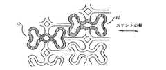
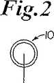
本発明による概して円筒形のステント10の好適な実施形態が図1−図4に示されている。該ステントは、図2及び4に示すように好ましくはニチノールもしくはステンレス鋼のような金属管を備えており、図1の平面図に示される形状にエッチングされるか好ましくはレーザーカットされている。図1の拡大詳細図が図3に示されている。該形状は、概して12で示された(明瞭にするために図3において黒くしてある)一連の曲線で囲まれた膨張セル素子から成り、該セル素子においては、比較的広い端部14が比較的狭い中央部16によって接合されている。セル12は、図1に示されるように、ステント10の長手方向軸に対して端と端を縦につないで長手方向に、そして再度図1に示されるように、実質的に平行の行に配列されている。長手方向に延びる複数の長い支持部材18が含まれており、各々1つはセル12の隣り合う行の間に配置されている。また、支持部材18と実質的に垂直であるのが好ましい円周方向に延びる複数の支持部材19が、セル12の行の間に位置付けられており、支持部材18の部分と交差して該部分をセル12の狭い中央部16に相互接続させる。図1aに見られるように、セル12はずらされた配列でもって配置されても良い。図1b及び1cは、セル12の異なる配列及び相互接続を示す。
【0005】
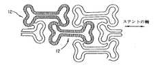
ステントが膨張されるとき、図4に示されるように、バルーン上で、セル12は、示された新しい形状をとり、ここに、ステントを構成する部材は、図1及び図3で用いられたのと同じ数字によって示されている。再度、明瞭にするために、1つのセルが、黒く示されている。
【0006】
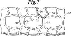
さて、図5−7を参照すると、概して22で示される本発明のもう1つのステントの実施の形態が示されている。この実施の形態において、図5及び図6に示すように、膨張セル24(図6に最も詳細に見ることができ黒い部分で示されている)は、図6に最もよく見える比較的広い端部26と、狭い中央部28とを有しており、第1の実施の形態について説明したように長手方向の行において端と端とをつないで配列されている。隣り合った端部26は、湾曲した端部32を有するセグメント30の形態にある一対の長手方向支持部材によって相互接続されている。円周方向に延びるセグメント34は、セル24の行の間を延びて狭い中央部28を相互接続する。
【0007】
ステントの半径方向への膨張時、例えばバルーン20上におけるように、その形状は、図6に矢印で示した方向の変形力によって、図7に示した形状に変化する。図7に示された素子は、図5及び6で同様の素子に対して示したのと同じ数字によって識別される。
【0008】
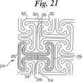
図20及び21は、図5−7の形状と幾分類似の形状を示すが、素子28を相互接続しない。
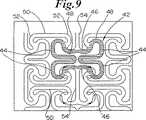
さて、図8−10を参照すると、本発明のもう1つのステントの実施形態が示されており、概して40で示されている。再度、図8及び図9に見られるように、膨張セル42(明瞭にするために黒くされた例)は、比較的広い端部44と狭い中央部46とを有している。端部は、内方に延びるループ部48を含んでいる。セル42は、先の実施形態におけるように、長手方向の行において端と端とをつないで配列されている。隣り合った端部44は、湾曲した端部52を有する一対の長手方向支持部材セグメント50によって相互接続される。円周方向に延びるセグメント54は、セル42の行の間に延びてセルの狭い中央部46を相互接続する。図8aは、セル42に対する形状の変形を示す。
【0009】
バルーン20上でステントが半径方向に膨張すると、形状は、図10に示されたものに変化する。矢印は、膨張時の変形の力の方向を示す。
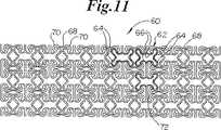
さて、図11及び12を参照すると、ステント60のさらにもう1つの実施の形態が示されている。再度、図11及び12に示されるように、膨張セル62(明瞭にするために黒くされた例)は、僅かな内方への曲げ部65を有する比較的広い端部64と、狭い中央部66とを有する。セル62は、先の実施の形態におけるように長手方向の行において端と端とをつないで配列されている。隣り合った端部64は、湾曲した端部70を有する一対の長手方向の支持部材セグメント68によって相互接続されている。円周方向に延びるセグメント72は、セル62の行の間に延びてセルの狭い中央部66を相互接続する。
【0010】
図13を参照すると、本発明のステントの固有の柔軟性が示されている。
バルーン20上でステントが半径方向に膨張すると、形状は、図14に示すものに変化する。
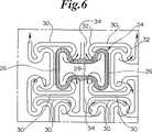
さて、図15及び16を参照すると、ステント80のさらにもう1つの実施の形態が示されており、形状は、図11−14のものと全く類似であるが、円周方向に延びる構造素子81が追加されている。再度、図16に最も良く見られるように、膨張セル82(明瞭にするために黒くされた例)は、僅かな内方への曲げ部85を有する比較的広い端部84と、狭い中央部86とを有する。セル82は、先の実施形態におけるように、長手方向の行において端と端とをつないで配列されている。隣り合った端部84は、湾曲した端部90を有する一対の長手方向支持部材セグメント88によって相互接続されている。円周方向に延びるセグメント92は、セル82の行の間に延びてセルの狭い中央部86を相互接続する。円周方向に延びるセグメント81は、支持部材セグメント88の対を相互接続する。
【0011】
バルーン20上でステントが半径方向に膨張すると、形状は、図17に示されるものに変化する。
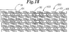
さて、図18及び19を参照すると、ステント形状100のさらにもう1つの実施の形態が示されている。前述のように、この実施の形態も図11−12のものと類似しているが、円周方向に延びるセグメント101は、図11―12に72として識別されるものとは異なって配列されている。この実施形態においては、円周方向に延びる部材101は、隣接するセル103(明瞭にするために黒くされた例)の隣り合った端の間に延びて、一端の頂部を隣接する端の底部に相互接続し、そして部材101は、その長さにおいて、僅かな湾曲部もしくは曲げ部105を有する。他の部材はすべて、先の図におけるのと同様に番号が付されている。
【0012】
図22は、ステントのさらに別の実施形態を示しており、相互接続を行う円周方向に延びる部材122を有したセル120から成る。該セルは、共通の辺もしくは端部材124を有し、接合されるセル128によって相互接続されるバンド126を形成するようグループで配列されている。
【0013】
本発明は異なった多くの形態で実施することができるけれども、ここでは、本発明の特定の好適な実施形態を詳細に説明した。この説明は、本発明の原理に関する例示を示すものであり、本発明を示された特定の実施形態に制限することを意図するものではない。
【0014】
上述の例及び開示は、説明するためのものであり、発明を網羅するものとしては意図していない。これらの例及び説明は、当業者に多くの変形及び代替を示唆するであろう。これらすべての代替及び変形も、添付の特許請求の範囲内に含められるものと意図している。当該技術に詳しいものは、ここに記載された特定の実施形態に対し他の等価物も認識するかもしれないが、この等価物も添付された特許請求の範囲に包含されるものと意図している。
【図面の簡単な説明】
【図1】 本発明のステント形状の膨張していない状態での実施形態の平面図である。
【図1a】 ステントを構成するセルのずらされた配列を示す、図1と同様の部分平面図である。
【図1b】 異なった配列及び異なった相互接続における、図1及び図1aと同様のセルを示す図である。
【図1c】 異なった配列及び異なった相互接続における、図1及び図1aと同様のセルを示す図である。
【図2】 通常の管状の膨張されない状態における本発明による図1のステントの端面図である。
【図3】 図1の部分の詳細を示す図である。
【図4】 バルーン上で膨張された図1及び図2のステントを示す図である。
【図5】 図1と類似の本発明のもう1つのステントの実施形態を膨張していない状態で示す平面図である。
【図6】 図5の部分の詳細を示す図である。
【図7】 バルーン上で膨張された図4のステントを示す図である。
【図8】 膨張していない状態のもう1つのステントの実施形態を示す図1及び図5と類似の平面図である。
【図8a】 図8に示すセル形状の変形例を示す部分平面図である。
【図9】 図8の部分の詳細を示す図である。
【図10】 バルーン上で膨張された図8のステントを示す図である。
【図11】 膨張していない状態でのステントのさらにもう1つの実施形態を示す、図1、5及び8と類似の平面図である。
【図12】 図11の部分の詳細を示す図である。
【図13】 膨張していない状態での柔軟性を示す膨張していないバルーン上での図11のステントを示す図である。
【図14】 バルーン上で膨張した図11のステントを示す図である。
【図15】 膨張していない状態でのステントのさらに別の実施形態を示す、図1、5、8及び11と同様の平面図である。
【図16】 図15の部分の詳細を示す図である。
【図17】 バルーン上で膨張された図15のステントを示す図である。
【図18】 膨張されていない状態でのステントのさらに別の実施形態を示す図1、5、8、11及び15と同様の平面図である。
【図19】 図18の部分の詳細を示す図である。
【図20】 膨張されていない状態でのステントのさらにもう1つの実施形態を示す、図1、5、8、11、15及び18と同様の平面図である。
【図21】 図20の部分詳細を示す図である。
【図22】 本発明の別の実施形態を示す平面図である。[0001]
Background of the Invention
1. Field of the Invention The present invention relates to improved shaped stents.
2. Brief description of the prior art Stents, after being introduced percutaneously, are radially expanded, typically an intravascular graft, which can be implanted across the lumen and radially expanded. A possible endoprosthesis. They have also been transplanted into the urinary tract and bile ducts. They are used to strengthen the body's vasculature and to prevent restenosis following angiogenesis in the vasculature. They can self-inflate or be inflated by internal radial forces, such as when mounted on a balloon.
[0002]
In the past, stents are generally tubular, but have been constructed in many shapes and made from many materials including metals and plastics. Conventional metals such as stainless steel have been used as having shape memory metals such as Nitinol. Stents have also been made from biodegradable plastic materials. Such stents have been formed from wires, tube stock, and the like.
[0003]
SUMMARY OF THE INVENTION The present invention provides a novel shape of the cells that make up a stent that is compatible with all of the conventional stents of the types described above and / or various types known in the art. There are many advantages to the new shape. The shape of the present invention, among other things, limits crimp and imparts compression resistance to the expanded stent. Other shapes other than cylindrical, such as square, triangle, octagon, etc. are also contemplated. The stent of the present invention is flexible and expandable in the longitudinal direction.
[0004]
Detailed Description of the Preferred Embodiments A preferred embodiment of a generally
[0005]
When the stent is expanded, as shown in FIG. 4, on the balloon, the
[0006]
5-7, another stent embodiment of the present invention, generally indicated at 22, is shown. In this embodiment, as shown in FIGS. 5 and 6, the expansion cell 24 (shown in black in the most detailed view in FIG. 6) has a relatively wide end that is best seen in FIG.
[0007]
When the stent is expanded in the radial direction, the shape thereof is changed to the shape shown in FIG. 7 by the deformation force in the direction indicated by the arrow in FIG. The elements shown in FIG. 7 are identified by the same numbers as shown for similar elements in FIGS.
[0008]
20 and 21 show a shape somewhat similar to the shape of FIGS. 5-7, but do not interconnect the
Referring now to FIGS. 8-10, another stent embodiment of the present invention is shown, generally indicated at 40. FIG. Again, as can be seen in FIGS. 8 and 9, the expansion cell 42 (example blacked for clarity) has a relatively
[0009]
As the stent expands radially on the
Referring now to FIGS. 11 and 12, yet another embodiment of the
[0010]
Referring to FIG. 13, the inherent flexibility of the stent of the present invention is shown.
As the stent expands radially on the
Referring now to FIGS. 15 and 16, yet another embodiment of a
[0011]
As the stent expands radially on the
18 and 19, yet another embodiment of the
[0012]
FIG. 22 shows yet another embodiment of a stent, which consists of a cell 120 having a
[0013]
Although the present invention can be implemented in many different forms, a specific preferred embodiment of the present invention has been described in detail herein. This description is an exemplification of the principles of the invention and is not intended to limit the invention to the particular embodiments illustrated.
[0014]
The above examples and disclosure are for illustrative purposes and are not intended to be exhaustive. These examples and description will suggest many variations and alternatives to one of ordinary skill in this art. All these alternatives and variations are intended to be included within the scope of the appended claims. Those skilled in the art may recognize other equivalents to the specific embodiments described herein, which equivalents are intended to be encompassed by the appended claims. Yes.
[Brief description of the drawings]
FIG. 1 is a plan view of an embodiment of the stent shape of the present invention in an unexpanded state.
FIG. 1a is a partial plan view similar to FIG. 1, showing a shifted arrangement of cells making up the stent.
FIG. 1b shows a cell similar to FIGS. 1 and 1a in a different arrangement and different interconnections.
FIG. 1c shows a cell similar to FIG. 1 and FIG. 1a in different arrangements and different interconnections.
2 is an end view of the stent of FIG. 1 according to the present invention in a normal tubular unexpanded state. FIG.
FIG. 3 is a diagram showing details of the portion of FIG. 1;
FIG. 4 shows the stent of FIGS. 1 and 2 inflated on a balloon.
FIG. 5 is a plan view showing another stent embodiment of the present invention similar to FIG. 1 in an unexpanded state.
6 is a diagram showing details of the portion of FIG.
FIG. 7 shows the stent of FIG. 4 inflated on a balloon.
FIG. 8 is a plan view similar to FIGS. 1 and 5 showing another stent embodiment in an unexpanded state.
8a is a partial plan view showing a modification of the cell shape shown in FIG.
FIG. 9 is a diagram showing details of the portion of FIG.
FIG. 10 shows the stent of FIG. 8 inflated on a balloon.
11 is a plan view similar to FIGS. 1, 5 and 8 showing yet another embodiment of the stent in an unexpanded state. FIG.
12 is a diagram showing details of the portion of FIG.
FIG. 13 shows the stent of FIG. 11 on an uninflated balloon showing flexibility in the uninflated state.
FIG. 14 shows the stent of FIG. 11 inflated on the balloon.
FIG. 15 is a plan view similar to FIGS. 1, 5, 8 and 11 showing yet another embodiment of the stent in an unexpanded state.
FIG. 16 is a diagram showing details of the portion of FIG. 15;
FIG. 17 shows the stent of FIG. 15 inflated on a balloon.
18 is a plan view similar to FIGS. 1, 5, 8, 11 and 15 showing yet another embodiment of the stent in an unexpanded state. FIG.
FIG. 19 is a diagram showing details of the portion of FIG.
FIG. 20 is a plan view similar to FIGS. 1, 5, 8, 11, 15 and 18 showing yet another embodiment of the stent in an unexpanded state.
21 is a diagram showing details of the portion of FIG.
FIG. 22 is a plan view showing another embodiment of the present invention.
Claims (10)
Translated fromJapaneseステントの平常時において、中央部は対向する曲線部が相互に接近し、幅広の端部は曲線部が周方向に延びることとを特徴とするステント。A cylindrical stent composed of a plurality of orderly arranged closed cell bodies to provide a closed expansion cell surrounded by a series of curves, the cell having a pair of wide ends and an end A narrower central portion, the wide end portion and the narrow central portion each have a plurality of curved portions, and the wide end portion is joined by the central portion, andthe wide end portion parts are a possible bent toward the central portion, the cell is arranged by connecting a longitudinally end to end in the longitudinal direction of the row relative to the longitudinal axis of the stent,the cells adjacent to the longitudinalsupport member Interconnected by,
In the normal state of the stent, a curved portion opposed to each other in the central portion approaches each other, and the curved portion extends in the circumferential direction at the wide end portion.
ステントは、さらに、
長手方向に延びる複数の長い支持部材を含み、セルの隣接する長手方向の行は少なくとも1つの長い支持部材により接合され、
支持部材と実質的に垂直に円周方向に延びる複数の接続部材を含み、該接続部材は、支持部材をセルの狭い中央部に相互接続させる、
請求項1に記載のステント。The longitudinal rows are substantially parallel;
The stent
Including a plurality of longitudinal support members extending longitudinally, adjacent longitudinal rows of cells joined by at least one long support member;
A plurality of connecting members extending circumferentially substantially perpendicular to the support member, the connecting members interconnecting the support member to a narrow central portion of the cell;
The stent according to claim 1.
一連の曲線で囲まれた、閉じた膨張セルを提供する複数の曲線形成体であって、セルは、一対の幅広の端部と同端部より狭小な中央部とを有し、同幅広の端部と狭小な中央部はそれぞれ複数の曲線部を有し、同幅広の端部は同中央部によって接合され、かつステントの長手方向軸に対する長手方向の行において長手方向に端と端とをつないで配列される、曲線形成体と、
隣接するセルの端を接続する長手方向の一対の接続部材と、
隣接する行のセルの間に延びる円周方向に延びる部材と、
を備えることと、
ステントの平常時において、中央部は対向する曲線部が相互に接近し、幅広の端部は曲線部が周方向に延びることとを特徴とするステント。A cylindrical stent,
A plurality of curve formers that provide a closed expansion cell surrounded by a series of curves, the cell having a pair of wide ends and a central portion narrower than the ends, The end portion and the narrow central portion each have a plurality of curved portions, the wide end portions are joined by the central portion, and the ends end to end in a longitudinal row with respect to the longitudinal axis of the stent. A curvilinear body arranged in a chain;
A pair of connecting members in the longitudinal direction connecting the ends of adjacent cells;
A circumferentially extending member extending between cells in adjacent rows;
Providing
In the normal state of the stent, a curved portion opposed to each other at the center portion is close to each other, and the curved portion extends in the circumferential direction at the wide end portion.
特徴とする請求項1に記載のステント。The stent of claim 1, further characterized in that the relatively wide end dimensions are substantially equal to each other.
ステントの平常時において、中央部は対向する曲線部が相互に接近し、幅広の端部は曲線部が周方向に延びることとを特徴とするステント。A cylindrically shaped stent having a longitudinal axis and a circumference, comprising a plurality of interconnected curvilinearly arranged in an array to provide individual closed expansion cells surrounded by a series of curves And the cell has a pair of wide end portions and a central portion narrower than the end portions, and the wide end portion and the narrow central portion each have a plurality of curved portions, and the wide end portions have the same width. Are joined by the central portion,the wide end portions are bent toward the central portion, and some of the cells end longitudinally in a longitudinal row relative to the longitudinal axis of the stent. Being arranged end to end, some of the cells being circumferentially arranged in a circumferential row relative to the circumferenceof the stentby interconnecting the central portions ;
In the normal state of the stent, a curved portion opposed to each other at the center portion is close to each other, and the curved portion extends in the circumferential direction at the wide end portion.
ステントの平常時において、中央部は対向する曲線部が相互に接近し、幅広の端部は曲線部が周方向に延びることとを特徴とするステント。A cylindrically shaped stent having a longitudinal axis, comprising a plurality of interconnected curved formers of the same shape and arranged in a series of curves to provide a closed expansion cell The cell has a pair of wide end portions and a central portion narrower than the end portions, and the wide end portion and the narrow central portion each have a plurality of curved portions, and The wide ends are joined by the central portion and arranged longitudinally end-to-end in a longitudinal row relative to the longitudinal axis of the stent, andthe wide ends are directed toward the central portion. Bend, the band is interconnected by a curve former shared between certain expansion cells located on adjacent edges of the band, and some cells constitute the band edges Less than the number of cells,
In the normal state of the stent, a curved portion opposed to each other at the center portion is close to each other, and the curved portion extends in the circumferential direction at the wide end portion.
Applications Claiming Priority (3)
| Application Number | Priority Date | Filing Date | Title |
|---|---|---|---|
| US08/947,620US6013091A (en) | 1997-10-09 | 1997-10-09 | Stent configurations |
| US08/947,620 | 1997-10-09 | ||
| PCT/US1998/021106WO1999018888A1 (en) | 1997-10-09 | 1998-10-06 | Improved stent configurations |
Publications (2)
| Publication Number | Publication Date |
|---|---|
| JP2001519204A JP2001519204A (en) | 2001-10-23 |
| JP4271846B2true JP4271846B2 (en) | 2009-06-03 |
Family
ID=25486437
Family Applications (1)
| Application Number | Title | Priority Date | Filing Date |
|---|---|---|---|
| JP2000515529AExpired - LifetimeJP4271846B2 (en) | 1997-10-09 | 1998-10-06 | Improved stent shape |
Country Status (8)
| Country | Link |
|---|---|
| US (4) | US6013091A (en) |
| EP (2) | EP1844741B1 (en) |
| JP (1) | JP4271846B2 (en) |
| AT (2) | ATE454114T1 (en) |
| CA (2) | CA2303344C (en) |
| DE (2) | DE69841444D1 (en) |
| ES (1) | ES2335363T3 (en) |
| WO (1) | WO1999018888A1 (en) |
Families Citing this family (149)
| Publication number | Priority date | Publication date | Assignee | Title |
|---|---|---|---|---|
| US7204848B1 (en) | 1995-03-01 | 2007-04-17 | Boston Scientific Scimed, Inc. | Longitudinally flexible expandable stent |
| US6241760B1 (en) | 1996-04-26 | 2001-06-05 | G. David Jang | Intravascular stent |
| US6235053B1 (en) | 1998-02-02 | 2001-05-22 | G. David Jang | Tubular stent consists of chevron-shape expansion struts and contralaterally attached diagonal connectors |
| US20040106985A1 (en) | 1996-04-26 | 2004-06-03 | Jang G. David | Intravascular stent |
| JP4636634B2 (en)* | 1996-04-26 | 2011-02-23 | ボストン サイエンティフィック サイムド,インコーポレイテッド | Intravascular stent |
| US6835203B1 (en) | 1996-11-04 | 2004-12-28 | Advanced Stent Technologies, Inc. | Extendible stent apparatus |
| US6325826B1 (en) | 1998-01-14 | 2001-12-04 | Advanced Stent Technologies, Inc. | Extendible stent apparatus |
| US6599316B2 (en) | 1996-11-04 | 2003-07-29 | Advanced Stent Technologies, Inc. | Extendible stent apparatus |
| US6692483B2 (en) | 1996-11-04 | 2004-02-17 | Advanced Stent Technologies, Inc. | Catheter with attached flexible side sheath |
| US8211167B2 (en) | 1999-12-06 | 2012-07-03 | Boston Scientific Scimed, Inc. | Method of using a catheter with attached flexible side sheath |
| US7220275B2 (en)* | 1996-11-04 | 2007-05-22 | Advanced Stent Technologies, Inc. | Stent with protruding branch portion for bifurcated vessels |
| EP1723931B1 (en)* | 1996-11-04 | 2012-01-04 | Advanced Stent Technologies, Inc. | Extendible stent apparatus and method for deploying the same |
| US6682536B2 (en) | 2000-03-22 | 2004-01-27 | Advanced Stent Technologies, Inc. | Guidewire introducer sheath |
| US7341598B2 (en)* | 1999-01-13 | 2008-03-11 | Boston Scientific Scimed, Inc. | Stent with protruding branch portion for bifurcated vessels |
| US7591846B2 (en)* | 1996-11-04 | 2009-09-22 | Boston Scientific Scimed, Inc. | Methods for deploying stents in bifurcations |
| GB9703859D0 (en)* | 1997-02-25 | 1997-04-16 | Plante Sylvain | Expandable intravascular stent |
| US20020133222A1 (en)* | 1997-03-05 | 2002-09-19 | Das Gladwin S. | Expandable stent having a plurality of interconnected expansion modules |
| EP0884029B1 (en)* | 1997-06-13 | 2004-12-22 | Gary J. Becker | Expandable intraluminal endoprosthesis |
| US6013091A (en)* | 1997-10-09 | 2000-01-11 | Scimed Life Systems, Inc. | Stent configurations |
| WO1999044543A1 (en) | 1998-03-04 | 1999-09-10 | Scimed Life Systems, Inc. | Improved stent cell configurations |
| US6093203A (en) | 1998-05-13 | 2000-07-25 | Uflacker; Renan | Stent or graft support structure for treating bifurcated vessels having different diameter portions and methods of use and implantation |
| US6461380B1 (en) | 1998-07-28 | 2002-10-08 | Advanced Cardiovascular Systems, Inc. | Stent configuration |
| US6193744B1 (en)* | 1998-09-10 | 2001-02-27 | Scimed Life Systems, Inc. | Stent configurations |
| US20060178727A1 (en)* | 1998-12-03 | 2006-08-10 | Jacob Richter | Hybrid amorphous metal alloy stent |
| US20060122691A1 (en)* | 1998-12-03 | 2006-06-08 | Jacob Richter | Hybrid stent |
| US20070219642A1 (en)* | 1998-12-03 | 2007-09-20 | Jacob Richter | Hybrid stent having a fiber or wire backbone |
| US8382821B2 (en)* | 1998-12-03 | 2013-02-26 | Medinol Ltd. | Helical hybrid stent |
| US20050033399A1 (en)* | 1998-12-03 | 2005-02-10 | Jacob Richter | Hybrid stent |
| US6743252B1 (en)* | 1998-12-18 | 2004-06-01 | Cook Incorporated | Cannula stent |
| US20050060027A1 (en)* | 1999-01-13 | 2005-03-17 | Advanced Stent Technologies, Inc. | Catheter balloon systems and methods |
| US7655030B2 (en) | 2003-07-18 | 2010-02-02 | Boston Scientific Scimed, Inc. | Catheter balloon systems and methods |
| US6368346B1 (en) | 1999-06-03 | 2002-04-09 | American Medical Systems, Inc. | Bioresorbable stent |
| US7387639B2 (en)* | 1999-06-04 | 2008-06-17 | Advanced Stent Technologies, Inc. | Short sleeve stent delivery catheter and methods |
| US6884258B2 (en) | 1999-06-04 | 2005-04-26 | Advanced Stent Technologies, Inc. | Bifurcation lesion stent delivery using multiple guidewires |
| US6689156B1 (en)* | 1999-09-23 | 2004-02-10 | Advanced Stent Technologies, Inc. | Stent range transducers and methods of use |
| WO2001021095A2 (en)* | 1999-09-23 | 2001-03-29 | Advanced Stent Technologies, Inc. | Bifurcation stent system and method |
| US20010047200A1 (en)* | 1999-10-13 | 2001-11-29 | Raymond Sun | Non-foreshortening intraluminal prosthesis |
| US6679910B1 (en)* | 1999-11-12 | 2004-01-20 | Latin American Devices Llc | Intraluminal stent |
| DE19957063A1 (en)* | 1999-11-26 | 2001-08-02 | Franz Herbst | Stent and method for its manufacture |
| WO2001041675A1 (en)* | 1999-12-07 | 2001-06-14 | Edwards Lifesciences Corporation | Novel enhanced flexible expandable stents |
| US7758627B2 (en)* | 2000-03-01 | 2010-07-20 | Medinol, Ltd. | Longitudinally flexible stent |
| US8920487B1 (en) | 2000-03-01 | 2014-12-30 | Medinol Ltd. | Longitudinally flexible stent |
| US7828835B2 (en) | 2000-03-01 | 2010-11-09 | Medinol Ltd. | Longitudinally flexible stent |
| US8496699B2 (en)* | 2000-03-01 | 2013-07-30 | Medinol Ltd. | Longitudinally flexible stent |
| SG86458A1 (en)* | 2000-03-01 | 2002-02-19 | Medinol Ltd | Longitudinally flexible stent |
| US6723119B2 (en)* | 2000-03-01 | 2004-04-20 | Medinol Ltd. | Longitudinally flexible stent |
| US7621947B2 (en) | 2000-03-01 | 2009-11-24 | Medinol, Ltd. | Longitudinally flexible stent |
| US7141062B1 (en)* | 2000-03-01 | 2006-11-28 | Medinol, Ltd. | Longitudinally flexible stent |
| US8202312B2 (en)* | 2000-03-01 | 2012-06-19 | Medinol Ltd. | Longitudinally flexible stent |
| DE10012460A1 (en)* | 2000-03-15 | 2001-09-20 | Biotronik Mess & Therapieg | Stent |
| US6616689B1 (en)* | 2000-05-03 | 2003-09-09 | Advanced Cardiovascular Systems, Inc. | Intravascular stent |
| US6440162B1 (en) | 2000-07-26 | 2002-08-27 | Advanced Cardiovascular Systems, Inc. | Stent having increased scaffolding expandable bar arms |
| AU2000269326A1 (en)* | 2000-08-24 | 2002-03-04 | Stenttech, Inc. Dba Stenttech | Expandable stent having a plurality of expansion cell modules |
| US7766956B2 (en) | 2000-09-22 | 2010-08-03 | Boston Scientific Scimed, Inc. | Intravascular stent and assembly |
| US6485508B1 (en)* | 2000-10-13 | 2002-11-26 | Mcguinness Colm P. | Low profile stent |
| US6506211B1 (en) | 2000-11-13 | 2003-01-14 | Scimed Life Systems, Inc. | Stent designs |
| US6929660B1 (en)* | 2000-12-22 | 2005-08-16 | Advanced Cardiovascular Systems, Inc. | Intravascular stent |
| US8617231B2 (en) | 2001-05-18 | 2013-12-31 | Boston Scientific Scimed, Inc. | Dual guidewire exchange catheter system |
| US20030069629A1 (en)* | 2001-06-01 | 2003-04-10 | Jadhav Balkrishna S. | Bioresorbable medical devices |
| US20020188342A1 (en)* | 2001-06-01 | 2002-12-12 | Rykhus Robert L. | Short-term bioresorbable stents |
| US6887215B2 (en) | 2001-06-01 | 2005-05-03 | Boston Scientific Scimed, Inc. | Compressible ureteral stent for comfort |
| US6629994B2 (en)* | 2001-06-11 | 2003-10-07 | Advanced Cardiovascular Systems, Inc. | Intravascular stent |
| US6939373B2 (en)* | 2003-08-20 | 2005-09-06 | Advanced Cardiovascular Systems, Inc. | Intravascular stent |
| US6635083B1 (en) | 2001-06-25 | 2003-10-21 | Advanced Cardiovascular Systems, Inc. | Stent with non-linear links and method of use |
| US6749629B1 (en) | 2001-06-27 | 2004-06-15 | Advanced Cardiovascular Systems, Inc. | Stent pattern with figure-eights |
| AU2002320456A1 (en) | 2001-07-26 | 2003-02-17 | Alveolus Inc. | Removable stent and method of using the same |
| IES20010828A2 (en)* | 2001-09-12 | 2003-03-19 | Medtronic Inc | Medical device for intraluminal endovascular stenting |
| US7147661B2 (en) | 2001-12-20 | 2006-12-12 | Boston Scientific Santa Rosa Corp. | Radially expandable stent |
| JP4331610B2 (en) | 2001-12-20 | 2009-09-16 | トリバスキュラー2,インコーポレイティド | Advanced endovascular graft |
| US7537607B2 (en)* | 2001-12-21 | 2009-05-26 | Boston Scientific Scimed, Inc. | Stent geometry for improved flexibility |
| EP2166505A3 (en)* | 2002-04-02 | 2010-10-06 | Verizon Business Global LLC | Billing system for communications services invoicing telephony and instant communications |
| US7128756B2 (en)* | 2002-05-08 | 2006-10-31 | Abbott Laboratories | Endoprosthesis having foot extensions |
| US6656220B1 (en) | 2002-06-17 | 2003-12-02 | Advanced Cardiovascular Systems, Inc. | Intravascular stent |
| DE10228529A1 (en)* | 2002-06-26 | 2004-01-22 | Admedes Schuessler Gmbh | stent |
| AU2003249309A1 (en)* | 2002-07-24 | 2004-02-09 | Advanced Stent Technologies, Inc. | Stents capable of controllably releasing histone deacetylase inhibitors |
| US7485139B1 (en) | 2002-10-10 | 2009-02-03 | Ciamacco Jr Sam | Stent delivery and deployment system |
| US7875068B2 (en) | 2002-11-05 | 2011-01-25 | Merit Medical Systems, Inc. | Removable biliary stent |
| US7637942B2 (en) | 2002-11-05 | 2009-12-29 | Merit Medical Systems, Inc. | Coated stent with geometry determinated functionality and method of making the same |
| US7959671B2 (en) | 2002-11-05 | 2011-06-14 | Merit Medical Systems, Inc. | Differential covering and coating methods |
| US7527644B2 (en) | 2002-11-05 | 2009-05-05 | Alveolus Inc. | Stent with geometry determinated functionality and method of making the same |
| DE10253633B4 (en)* | 2002-11-13 | 2011-08-11 | BIOTRONIK GmbH & Co. KG, 12359 | supporting structure |
| US7172624B2 (en)* | 2003-02-06 | 2007-02-06 | Boston Scientific Scimed, Inc. | Medical device with magnetic resonance visibility enhancing structure |
| US7179286B2 (en)* | 2003-02-21 | 2007-02-20 | Boston Scientific Scimed, Inc. | Stent with stepped connectors |
| US20040181186A1 (en)* | 2003-03-13 | 2004-09-16 | Scimed Life Systems, Inc. | Medical device |
| US7625401B2 (en)* | 2003-05-06 | 2009-12-01 | Abbott Laboratories | Endoprosthesis having foot extensions |
| US7625398B2 (en)* | 2003-05-06 | 2009-12-01 | Abbott Laboratories | Endoprosthesis having foot extensions |
| US6846323B2 (en) | 2003-05-15 | 2005-01-25 | Advanced Cardiovascular Systems, Inc. | Intravascular stent |
| US7131993B2 (en)* | 2003-06-25 | 2006-11-07 | Boston Scientific Scimed, Inc. | Varying circumferential spanned connectors in a stent |
| US9155639B2 (en)* | 2009-04-22 | 2015-10-13 | Medinol Ltd. | Helical hybrid stent |
| US9039755B2 (en) | 2003-06-27 | 2015-05-26 | Medinol Ltd. | Helical hybrid stent |
| US8298280B2 (en)* | 2003-08-21 | 2012-10-30 | Boston Scientific Scimed, Inc. | Stent with protruding branch portion for bifurcated vessels |
| US7344557B2 (en)* | 2003-11-12 | 2008-03-18 | Advanced Stent Technologies, Inc. | Catheter balloon systems and methods |
| GB0402103D0 (en)* | 2004-02-02 | 2004-03-03 | Hengelmolen Rudy | Tubular graft |
| US7763064B2 (en)* | 2004-06-08 | 2010-07-27 | Medinol, Ltd. | Stent having struts with reverse direction curvature |
| JP5054524B2 (en) | 2004-06-08 | 2012-10-24 | アドバンスド ステント テクノロジーズ, インコーポレイテッド | Stent with protruding branch for branch pipe |
| US20070292478A1 (en) | 2004-08-30 | 2007-12-20 | Popowski Youri | Medical Implant Provided with Inhibitors of Atp Synthesis |
| US9427340B2 (en)* | 2004-12-14 | 2016-08-30 | Boston Scientific Scimed, Inc. | Stent with protruding branch portion for bifurcated vessels |
| US8317855B2 (en)* | 2005-05-26 | 2012-11-27 | Boston Scientific Scimed, Inc. | Crimpable and expandable side branch cell |
| EP2364676B1 (en)* | 2005-06-30 | 2018-12-19 | Abbott Laboratories | Endoprosthesis having foot extensions |
| US8038706B2 (en)* | 2005-09-08 | 2011-10-18 | Boston Scientific Scimed, Inc. | Crown stent assembly |
| US20070112418A1 (en) | 2005-11-14 | 2007-05-17 | Boston Scientific Scimed, Inc. | Stent with spiral side-branch support designs |
| US8343211B2 (en)* | 2005-12-14 | 2013-01-01 | Boston Scientific Scimed, Inc. | Connectors for bifurcated stent |
| US8435284B2 (en)* | 2005-12-14 | 2013-05-07 | Boston Scientific Scimed, Inc. | Telescoping bifurcated stent |
| US20070142904A1 (en)* | 2005-12-20 | 2007-06-21 | Boston Scientific Scimed, Inc. | Bifurcated stent with multiple locations for side branch access |
| US7540881B2 (en)* | 2005-12-22 | 2009-06-02 | Boston Scientific Scimed, Inc. | Bifurcation stent pattern |
| US20070191926A1 (en)* | 2006-02-14 | 2007-08-16 | Advanced Cardiovascular Systems, Inc. | Stent pattern for high stent retention |
| US8821561B2 (en)* | 2006-02-22 | 2014-09-02 | Boston Scientific Scimed, Inc. | Marker arrangement for bifurcation catheter |
| US7833264B2 (en)* | 2006-03-06 | 2010-11-16 | Boston Scientific Scimed, Inc. | Bifurcated stent |
| US20070208419A1 (en)* | 2006-03-06 | 2007-09-06 | Boston Scientific Scimed, Inc. | Bifurcation stent with uniform side branch projection |
| US8298278B2 (en)* | 2006-03-07 | 2012-10-30 | Boston Scientific Scimed, Inc. | Bifurcated stent with improvement securement |
| US8043358B2 (en)* | 2006-03-29 | 2011-10-25 | Boston Scientific Scimed, Inc. | Stent with overlap and high extension |
| US8348991B2 (en)* | 2006-03-29 | 2013-01-08 | Boston Scientific Scimed, Inc. | Stent with overlap and high expansion |
| US7744643B2 (en) | 2006-05-04 | 2010-06-29 | Boston Scientific Scimed, Inc. | Displaceable stent side branch structure |
| US8460364B2 (en)* | 2006-07-20 | 2013-06-11 | Orbusneich Medical, Inc. | Bioabsorbable polymeric medical device |
| US7988720B2 (en) | 2006-09-12 | 2011-08-02 | Boston Scientific Scimed, Inc. | Longitudinally flexible expandable stent |
| US8778009B2 (en)* | 2006-10-06 | 2014-07-15 | Abbott Cardiovascular Systems Inc. | Intravascular stent |
| US7951191B2 (en)* | 2006-10-10 | 2011-05-31 | Boston Scientific Scimed, Inc. | Bifurcated stent with entire circumferential petal |
| US7842082B2 (en) | 2006-11-16 | 2010-11-30 | Boston Scientific Scimed, Inc. | Bifurcated stent |
| US8118861B2 (en) | 2007-03-28 | 2012-02-21 | Boston Scientific Scimed, Inc. | Bifurcation stent and balloon assemblies |
| US8486134B2 (en) | 2007-08-01 | 2013-07-16 | Boston Scientific Scimed, Inc. | Bifurcation treatment system and methods |
| US7959669B2 (en) | 2007-09-12 | 2011-06-14 | Boston Scientific Scimed, Inc. | Bifurcated stent with open ended side branch support |
| US8066755B2 (en) | 2007-09-26 | 2011-11-29 | Trivascular, Inc. | System and method of pivoted stent deployment |
| US8663309B2 (en) | 2007-09-26 | 2014-03-04 | Trivascular, Inc. | Asymmetric stent apparatus and method |
| US8226701B2 (en) | 2007-09-26 | 2012-07-24 | Trivascular, Inc. | Stent and delivery system for deployment thereof |
| US10159557B2 (en) | 2007-10-04 | 2018-12-25 | Trivascular, Inc. | Modular vascular graft for low profile percutaneous delivery |
| US8328861B2 (en) | 2007-11-16 | 2012-12-11 | Trivascular, Inc. | Delivery system and method for bifurcated graft |
| US8083789B2 (en) | 2007-11-16 | 2011-12-27 | Trivascular, Inc. | Securement assembly and method for expandable endovascular device |
| US7833266B2 (en) | 2007-11-28 | 2010-11-16 | Boston Scientific Scimed, Inc. | Bifurcated stent with drug wells for specific ostial, carina, and side branch treatment |
| US8277501B2 (en)* | 2007-12-21 | 2012-10-02 | Boston Scientific Scimed, Inc. | Bi-stable bifurcated stent petal geometry |
| US8747456B2 (en)* | 2007-12-31 | 2014-06-10 | Boston Scientific Scimed, Inc. | Bifurcation stent delivery system and methods |
| US20090240318A1 (en)* | 2008-03-19 | 2009-09-24 | Boston Scientific Scimed, Inc. | Stent expansion column, strut and connector slit design |
| US8531024B2 (en)* | 2008-03-25 | 2013-09-10 | Bridge Semiconductor Corporation | Semiconductor chip assembly with post/base heat spreader and multilevel conductive trace |
| US8932340B2 (en) | 2008-05-29 | 2015-01-13 | Boston Scientific Scimed, Inc. | Bifurcated stent and delivery system |
| US8377108B2 (en) | 2008-06-02 | 2013-02-19 | Boston Scientific Scimed, Inc. | Staggered two balloon bifurcation catheter assembly and methods |
| JP5662310B2 (en)* | 2008-06-05 | 2015-01-28 | ボストン サイエンティフィック サイムド,インコーポレイテッドBoston Scientific Scimed,Inc. | Shrinkable branch device and method of manufacturing the same |
| WO2009149405A1 (en)* | 2008-06-05 | 2009-12-10 | Boston Scientific Scimed, Inc. | Balloon bifurcated lumen treatment |
| WO2010042854A1 (en)* | 2008-10-10 | 2010-04-15 | Orbusneich Medical, Inc. | Bioabsorbable polymeric medical device |
| US8103140B2 (en) | 2009-06-01 | 2012-01-24 | Honeywell International Inc. | Interferometric fiber optic gyroscope with silicon optical bench front-end |
| WO2011120050A1 (en)* | 2010-03-26 | 2011-09-29 | Thubrikar Aortic Valve, Inc. | Valve component, frame component and prosthetic valve device including the same for implantation in a body lumen |
| US8858615B2 (en)* | 2010-05-19 | 2014-10-14 | National Taiwan University | Preventing vascular stenosis of cardiovascular stent |
| ES2374382B2 (en)* | 2011-10-27 | 2012-12-05 | Javier Gallastegui Goiburu | STENT |
| US8992595B2 (en) | 2012-04-04 | 2015-03-31 | Trivascular, Inc. | Durable stent graft with tapered struts and stable delivery methods and devices |
| US9498363B2 (en) | 2012-04-06 | 2016-11-22 | Trivascular, Inc. | Delivery catheter for endovascular device |
| JP6220386B2 (en) | 2012-05-14 | 2017-10-25 | シー・アール・バード・インコーポレーテッドC R Bard Incorporated | Uniformly expandable stent |
| USD723165S1 (en) | 2013-03-12 | 2015-02-24 | C. R. Bard, Inc. | Stent |
| US9381103B2 (en)* | 2014-10-06 | 2016-07-05 | Abbott Cardiovascular Systems Inc. | Stent with elongating struts |
| US10905578B2 (en) | 2017-02-02 | 2021-02-02 | C. R. Bard, Inc. | Short stent |
| US10238513B2 (en) | 2017-07-19 | 2019-03-26 | Abbott Cardiovascular Systems Inc. | Intravascular stent |
| CN108969165B (en)* | 2018-06-13 | 2020-08-07 | 哈尔滨工业大学 | 4D printing shape memory polymer composite material tracheal stent and preparation method thereof |
Family Cites Families (58)
| Publication number | Priority date | Publication date | Assignee | Title |
|---|---|---|---|---|
| US5102417A (en) | 1985-11-07 | 1992-04-07 | Expandable Grafts Partnership | Expandable intraluminal graft, and method and apparatus for implanting an expandable intraluminal graft |
| US5133732A (en)* | 1987-10-19 | 1992-07-28 | Medtronic, Inc. | Intravascular stent |
| JPH04283885A (en)* | 1991-03-13 | 1992-10-08 | Alps Electric Co Ltd | Automatic identification decoder |
| CA2079417C (en)* | 1991-10-28 | 2003-01-07 | Lilip Lau | Expandable stents and method of making same |
| DE4306431C2 (en)* | 1993-03-02 | 2000-04-20 | Hengst Walter Gmbh & Co Kg | Device for separating contaminants from the lubricating oil of an internal combustion engine |
| GB2281865B (en) | 1993-09-16 | 1997-07-30 | Cordis Corp | Endoprosthesis having multiple laser welded junctions,method and procedure |
| FR2710834B1 (en)* | 1993-10-05 | 1995-12-22 | Guerbet Sa | Expandable tubular organ for intraluminal endoprosthesis, intraluminal endoprosthesis, manufacturing process. |
| JP2703510B2 (en) | 1993-12-28 | 1998-01-26 | アドヴァンスド カーディオヴァスキュラー システムズ インコーポレーテッド | Expandable stent and method of manufacturing the same |
| US5449373A (en)* | 1994-03-17 | 1995-09-12 | Medinol Ltd. | Articulated stent |
| US5733303A (en)* | 1994-03-17 | 1998-03-31 | Medinol Ltd. | Flexible expandable stent |
| US5630829A (en)* | 1994-12-09 | 1997-05-20 | Intervascular, Inc. | High hoop strength intraluminal stent |
| US5591226A (en)* | 1995-01-23 | 1997-01-07 | Schneider (Usa) Inc. | Percutaneous stent-graft and method for delivery thereof |
| DE69622231T2 (en) | 1995-03-01 | 2002-12-05 | Scimed Life Systems, Inc. | LENGTHFLEXIBLE AND EXPANDABLE STENT |
| US5591197A (en)* | 1995-03-14 | 1997-01-07 | Advanced Cardiovascular Systems, Inc. | Expandable stent forming projecting barbs and method for deploying |
| ES2119527T5 (en) | 1995-04-01 | 2006-11-16 | Variomed Ag | STENT DEVICE FOR TRANSLUMINAL IMPLEMENTATION IN HOLLOW ORGANS. |
| IL123039A (en)* | 1995-07-25 | 2002-02-10 | Medstent Inc | Expandible stent |
| US5894406A (en)* | 1995-09-05 | 1999-04-13 | Blend; Michael L. | Elevated separate external keyboard apparatus for use with portable computer |
| US5776161A (en) | 1995-10-16 | 1998-07-07 | Instent, Inc. | Medical stents, apparatus and method for making same |
| AU7458596A (en) | 1995-10-20 | 1997-05-07 | Bandula Wijay | Vascular stent |
| US6203569B1 (en) | 1996-01-04 | 2001-03-20 | Bandula Wijay | Flexible stent |
| WO1997025937A1 (en) | 1996-01-18 | 1997-07-24 | Jang G David | Programmable variably flexible modular stents |
| US5895406A (en)* | 1996-01-26 | 1999-04-20 | Cordis Corporation | Axially flexible stent |
| US5695516A (en)* | 1996-02-21 | 1997-12-09 | Iso Stent, Inc. | Longitudinally elongating balloon expandable stent |
| DE29615969U1 (en)* | 1996-02-29 | 1996-10-31 | Medinol Ltd., Tel Aviv | Stent |
| CA2192520A1 (en)* | 1996-03-05 | 1997-09-05 | Ian M. Penn | Expandable stent and method for delivery of same |
| EP1066804B1 (en)* | 1996-03-05 | 2004-07-14 | Evysio Medical Devices Ulc | Expandable stent |
| US6334871B1 (en)* | 1996-03-13 | 2002-01-01 | Medtronic, Inc. | Radiopaque stent markers |
| DE19614160A1 (en) | 1996-04-10 | 1997-10-16 | Variomed Ag | Stent for transluminal implantation in hollow organs |
| US5922021A (en) | 1996-04-26 | 1999-07-13 | Jang; G. David | Intravascular stent |
| US5669932A (en)* | 1996-05-29 | 1997-09-23 | Isostent, Inc. | Means for accurately positioning an expandable stent |
| US5697971A (en)* | 1996-06-11 | 1997-12-16 | Fischell; Robert E. | Multi-cell stent with cells having differing characteristics |
| US5755776A (en) | 1996-10-04 | 1998-05-26 | Al-Saadon; Khalid | Permanent expandable intraluminal tubular stent |
| US5968093A (en) | 1996-10-28 | 1999-10-19 | Biotronik Mess-And Therapiegerate Gmbh & Co. | Stent |
| WO1998018405A1 (en) | 1996-10-28 | 1998-05-07 | Biotronik Mess- Und Therapiegeräte Gmbh & Co. | Expandable interluminal device |
| WO1998020810A1 (en) | 1996-11-12 | 1998-05-22 | Medtronic, Inc. | Flexible, radially expansible luminal prostheses |
| JP4188431B2 (en) | 1996-11-29 | 2008-11-26 | 株式会社パイオラックス | Stent |
| JP3519565B2 (en) | 1997-01-24 | 2004-04-19 | 株式会社パイオラックス | Stent |
| JP3798090B2 (en) | 1996-12-06 | 2006-07-19 | 株式会社パイオラックス | Stent |
| DE29701758U1 (en)* | 1997-02-01 | 1997-03-27 | Jomed Implantate GmbH, 72414 Rangendingen | Radially expandable stent for implantation in a body vessel, particularly in the area of a vascular branch |
| US5827321A (en) | 1997-02-07 | 1998-10-27 | Cornerstone Devices, Inc. | Non-Foreshortening intraluminal prosthesis |
| DE29702671U1 (en)* | 1997-02-17 | 1997-04-10 | Jomed Implantate GmbH, 72414 Rangendingen | Stent |
| US5810872A (en) | 1997-03-14 | 1998-09-22 | Kanesaka; Nozomu | Flexible stent |
| US5718713A (en) | 1997-04-10 | 1998-02-17 | Global Therapeutics, Inc. | Surgical stent having a streamlined contour |
| IT1292295B1 (en)* | 1997-04-29 | 1999-01-29 | Sorin Biomedica Cardio Spa | ANGIOPLASTIC STENT |
| US5741327A (en)* | 1997-05-06 | 1998-04-21 | Global Therapeutics, Inc. | Surgical stent featuring radiopaque markers |
| DE29708689U1 (en)* | 1997-05-15 | 1997-07-17 | Jomed Implantate GmbH, 72414 Rangendingen | Coronary stent |
| DE29708879U1 (en)* | 1997-05-20 | 1997-07-31 | Jomed Implantate GmbH, 72414 Rangendingen | Coronary stent |
| EP0884029B1 (en) | 1997-06-13 | 2004-12-22 | Gary J. Becker | Expandable intraluminal endoprosthesis |
| EP0890346A1 (en) | 1997-06-13 | 1999-01-13 | Gary J. Becker | Expandable intraluminal endoprosthesis |
| DE29716476U1 (en) | 1997-09-13 | 1997-12-18 | Convent, Gerd, 47829 Krefeld | Stenosis treatment stent |
| US6013091A (en) | 1997-10-09 | 2000-01-11 | Scimed Life Systems, Inc. | Stent configurations |
| WO1999044543A1 (en)* | 1998-03-04 | 1999-09-10 | Scimed Life Systems, Inc. | Improved stent cell configurations |
| US5935162A (en)* | 1998-03-16 | 1999-08-10 | Medtronic, Inc. | Wire-tubular hybrid stent |
| US6042597A (en)* | 1998-10-23 | 2000-03-28 | Scimed Life Systems, Inc. | Helical stent design |
| DE60326699D1 (en) | 2002-01-28 | 2009-04-30 | Orbusneich Medical Inc | EXPANDED OSTIUM DOPROTHESIS AND FEEDING SYSTEM |
| US7128756B2 (en) | 2002-05-08 | 2006-10-31 | Abbott Laboratories | Endoprosthesis having foot extensions |
| US7625401B2 (en) | 2003-05-06 | 2009-12-01 | Abbott Laboratories | Endoprosthesis having foot extensions |
| US7625398B2 (en) | 2003-05-06 | 2009-12-01 | Abbott Laboratories | Endoprosthesis having foot extensions |
- 1997
- 1997-10-09USUS08/947,620patent/US6013091A/ennot_activeExpired - Lifetime
- 1998
- 1998-10-06CACA002303344Apatent/CA2303344C/ennot_activeExpired - Fee Related
- 1998-10-06EPEP07014258Apatent/EP1844741B1/ennot_activeExpired - Lifetime
- 1998-10-06ESES07014258Tpatent/ES2335363T3/ennot_activeExpired - Lifetime
- 1998-10-06JPJP2000515529Apatent/JP4271846B2/ennot_activeExpired - Lifetime
- 1998-10-06EPEP98950972Apatent/EP1027012B1/ennot_activeExpired - Lifetime
- 1998-10-06DEDE69841444Tpatent/DE69841444D1/ennot_activeExpired - Lifetime
- 1998-10-06DEDE69838428Tpatent/DE69838428T2/ennot_activeExpired - Lifetime
- 1998-10-06ATAT07014258Tpatent/ATE454114T1/ennot_activeIP Right Cessation
- 1998-10-06CACA2592831Apatent/CA2592831C/ennot_activeExpired - Fee Related
- 1998-10-06ATAT98950972Tpatent/ATE372746T1/ennot_activeIP Right Cessation
- 1998-10-06WOPCT/US1998/021106patent/WO1999018888A1/enactiveIP Right Grant
- 1999
- 1999-05-21USUS09/316,827patent/US6416538B1/ennot_activeExpired - Lifetime
- 2002
- 2002-05-31USUS10/160,494patent/US7335225B2/ennot_activeExpired - Fee Related
- 2008
- 2008-02-25USUS12/036,559patent/US7951187B2/ennot_activeExpired - Fee Related
Also Published As
| Publication number | Publication date |
|---|---|
| ATE372746T1 (en) | 2007-09-15 |
| ATE454114T1 (en) | 2010-01-15 |
| US6013091A (en) | 2000-01-11 |
| JP2001519204A (en) | 2001-10-23 |
| US7951187B2 (en) | 2011-05-31 |
| ES2335363T3 (en) | 2010-03-25 |
| CA2592831A1 (en) | 1999-04-22 |
| CA2303344A1 (en) | 1999-04-22 |
| DE69841444D1 (en) | 2010-02-25 |
| EP1844741A3 (en) | 2007-10-24 |
| EP1844741A2 (en) | 2007-10-17 |
| EP1027012A1 (en) | 2000-08-16 |
| WO1999018888A9 (en) | 1999-07-01 |
| US6416538B1 (en) | 2002-07-09 |
| DE69838428D1 (en) | 2007-10-25 |
| US20020151962A1 (en) | 2002-10-17 |
| EP1027012B1 (en) | 2007-09-12 |
| EP1844741B1 (en) | 2010-01-06 |
| CA2592831C (en) | 2010-04-13 |
| US7335225B2 (en) | 2008-02-26 |
| WO1999018888A1 (en) | 1999-04-22 |
| CA2303344C (en) | 2007-08-21 |
| US20080167706A1 (en) | 2008-07-10 |
| DE69838428T2 (en) | 2008-01-17 |
Similar Documents
| Publication | Publication Date | Title |
|---|---|---|
| JP4271846B2 (en) | Improved stent shape | |
| JP4002999B2 (en) | Improved stent shape | |
| US7988718B2 (en) | Stent configurations | |
| US8317851B2 (en) | Longitudinally flexible stent | |
| US8585751B2 (en) | Intravascular hinge stent | |
| EP1753368B1 (en) | Stent having struts with reverse direction curvature | |
| US6312460B2 (en) | Intravascular hinge stent | |
| US6331189B1 (en) | Flexible medical stent | |
| US20100131047A1 (en) | Stent Cell Configurations | |
| JP2002541910A (en) | Medical device for intraluminal intravascular stent | |
| GB2369062A (en) | Extendable stent |
Legal Events
| Date | Code | Title | Description |
|---|---|---|---|
| A621 | Written request for application examination | Free format text:JAPANESE INTERMEDIATE CODE: A621 Effective date:20050823 | |
| A131 | Notification of reasons for refusal | Free format text:JAPANESE INTERMEDIATE CODE: A131 Effective date:20071211 | |
| A521 | Request for written amendment filed | Free format text:JAPANESE INTERMEDIATE CODE: A523 Effective date:20080311 | |
| A131 | Notification of reasons for refusal | Free format text:JAPANESE INTERMEDIATE CODE: A131 Effective date:20080701 | |
| A601 | Written request for extension of time | Free format text:JAPANESE INTERMEDIATE CODE: A601 Effective date:20081001 | |
| A602 | Written permission of extension of time | Free format text:JAPANESE INTERMEDIATE CODE: A602 Effective date:20081008 | |
| A601 | Written request for extension of time | Free format text:JAPANESE INTERMEDIATE CODE: A601 Effective date:20081031 | |
| A602 | Written permission of extension of time | Free format text:JAPANESE INTERMEDIATE CODE: A602 Effective date:20081110 | |
| A601 | Written request for extension of time | Free format text:JAPANESE INTERMEDIATE CODE: A601 Effective date:20081201 | |
| A602 | Written permission of extension of time | Free format text:JAPANESE INTERMEDIATE CODE: A602 Effective date:20081208 | |
| A521 | Request for written amendment filed | Free format text:JAPANESE INTERMEDIATE CODE: A523 Effective date:20081225 | |
| TRDD | Decision of grant or rejection written | ||
| A01 | Written decision to grant a patent or to grant a registration (utility model) | Free format text:JAPANESE INTERMEDIATE CODE: A01 Effective date:20090217 | |
| A01 | Written decision to grant a patent or to grant a registration (utility model) | Free format text:JAPANESE INTERMEDIATE CODE: A01 | |
| A61 | First payment of annual fees (during grant procedure) | Free format text:JAPANESE INTERMEDIATE CODE: A61 Effective date:20090226 | |
| FPAY | Renewal fee payment (event date is renewal date of database) | Free format text:PAYMENT UNTIL: 20120306 Year of fee payment:3 | |
| R150 | Certificate of patent or registration of utility model | Free format text:JAPANESE INTERMEDIATE CODE: R150 | |
| FPAY | Renewal fee payment (event date is renewal date of database) | Free format text:PAYMENT UNTIL: 20120306 Year of fee payment:3 | |
| FPAY | Renewal fee payment (event date is renewal date of database) | Free format text:PAYMENT UNTIL: 20130306 Year of fee payment:4 |