Movatterモバイル変換


[0]ホーム

URL:


JP4271641B2 - How to replace the rear part of the body frame - Google Patents

How to replace the rear part of the body frame
Download PDF

Info

Publication number
JP4271641B2
JP4271641B2JP2004289271AJP2004289271AJP4271641B2JP 4271641 B2JP4271641 B2JP 4271641B2JP 2004289271 AJP2004289271 AJP 2004289271AJP 2004289271 AJP2004289271 AJP 2004289271AJP 4271641 B2JP4271641 B2JP 4271641B2
Authority
JP
Japan
Prior art keywords
body frame
vehicle body
arm
cushion
suspension
Prior art date
Legal status (The legal status is an assumption and is not a legal conclusion. Google has not performed a legal analysis and makes no representation as to the accuracy of the status listed.)
Expired - Fee Related
Application number
JP2004289271A
Other languages
Japanese (ja)
Other versions
JP2006103374A (en
Inventor
伸治 ▲高▼橋
誠二 英
Current Assignee (The listed assignees may be inaccurate. Google has not performed a legal analysis and makes no representation or warranty as to the accuracy of the list.)
Honda Motor Co Ltd
Original Assignee
Honda Motor Co Ltd
Priority date (The priority date is an assumption and is not a legal conclusion. Google has not performed a legal analysis and makes no representation as to the accuracy of the date listed.)
Filing date
Publication date
Application filed by Honda Motor Co LtdfiledCriticalHonda Motor Co Ltd
Priority to JP2004289271ApriorityCriticalpatent/JP4271641B2/en
Priority to AU2005203450Aprioritypatent/AU2005203450B2/en
Priority to BRPI0503634Aprioritypatent/BRPI0503634B1/en
Priority to MYPI20054049Aprioritypatent/MY140545A/en
Priority to CNB2005100938272Aprioritypatent/CN100465051C/en
Priority to CA002517662Aprioritypatent/CA2517662C/en
Priority to MXPA05009753Aprioritypatent/MXPA05009753A/en
Priority to PT05255856Tprioritypatent/PT1642814E/en
Priority to ES05255856Tprioritypatent/ES2376553T3/en
Priority to EP05255856Aprioritypatent/EP1642814B1/en
Priority to US11/231,889prioritypatent/US7434822B2/en
Publication of JP2006103374ApublicationCriticalpatent/JP2006103374A/en
Application grantedgrantedCritical
Publication of JP4271641B2publicationCriticalpatent/JP4271641B2/en
Anticipated expirationlegal-statusCritical
Expired - Fee Relatedlegal-statusCriticalCurrent

Links

Images

Classifications

Landscapes

Description

Translated fromJapanese

この発明は、二つ以上の後輪を有する鞍乗り型車両の車体フレームのリア部交換方法に関する。The present invention relates to arear part replacement method for abody frameof a saddle-ride type vehicle having two or more rear wheels.

従来、上述のような車両においては、スイングアーム式のリアサスペンションが採用されたものがある(例えば、特許文献1参照。)。
実公平1−29194号公報
Conventionally, some of the vehicles described above employ a swing arm type rear suspension (see, for example, Patent Document 1).
Japanese Utility Model Publication No. 1-29194

ところで、上記車両の用途によっては、独立懸架式のリアサスペンションが採用されたものもある。このようにリアサスペンション形式が異なる車両間においては、通常は車体フレームの形態も異なるものとされるが、コストダウンの観点からも、このような各車両間において車体フレームを共用できるような構成が要望されている。
そこでこの発明は、リアサスペンション形式が異なる車両間においても車体フレームを共用することができる車体フレームのリア部交換方法を提供する。
By the way, depending on the use of the vehicle, there may be employed an independent suspension type rear suspension. In this way, between vehicles with different rear suspension types, the form of the body frame is usually different, but from the viewpoint of cost reduction, such a structure that the body frame can be shared between the respective vehicles is used. It is requested.
Accordingly, the present invention provides arear part replacement method for abody frame that can share a body frame even between vehicles having different rear suspension types.

上記課題の解決手段として、請求項1に記載した発明は、輪(例えば実施例の各前輪2)を懸架するフロント部(例えば実施例のフロント部4a)と、エンジン(例えば実施例のエンジン5)を支持するセンタ部(例えば実施例のセンタ部4b)と、シートレールを兼ねるリア部(例えば実施例のリア部4c)とを有する車体フレーム(例えば実施例の車体フレーム4)を備え、スイングアーム式リアサスペンションと独立懸架式リアサスペンションとを変更して取付可能な鞍乗り型車両の車体フレームのリア部交換方法であって、スイングアーム式リアサスペンションを独立懸架式リアサスペンションに変更する場合、前記センタ部に設けられた、少なくとも二つの後輪(例えば実施例の各後輪3)を懸架するスイングアーム(例えば実施例のスイングアーム71)が支持されるスイングアーム支持部(例えば実施例の各ピボットブラケット49)と、前記センタ部もしくはリア部に設けられた、リアクッション(例えば実施例のリアクッションユニット72)が支持されるリアクッション支持部(例えば実施例のアッパマウント57a)とを利用して、前記車体フレームに独立懸架式リアサスペンション用のサブフレーム(例えば実施例のサブフレームアッシ140,150)を取り付けることを特徴とする。As means for solving the above problems, the invention described inclaim 1, and (thefront wheels 2 of the Examples) front portion for suspending afront wheel (for example, thefront section 4a of the embodiment), the engine (e.g., Example enginewith 5) center portion for supporting (for example, acenter portion 4b of the embodiment), a rear portion serving also as a seat rail(e.g.rear portion 4c of the embodiment) andthe body frame to have a(e.g. body frame 4 in the embodiment)The rear part replacement method of thebody frame ofa saddle-ride type vehicle thatcan be mounted by changing a swing arm type rear suspension and an independent suspension type rear suspension, andthe swing arm type rear suspension is changed to an independent suspension type rear suspension If, provided in the centerportion, the swing arm for suspending the at least two rear wheels (e.g.,rear wheels 3 of example) (e.g. real A swing arm supportingportion Example swing arm 71) is supported (for example thepivot brackets 49 in the embodiment), provided in the center portion or a rearportion, therear cushion unit 72 of the rear cushion (for example embodiment) rear cushion supportingportion supported and (upper mount 57a in the examples) by utilizing, to attach a (sub-frame assembly 140, 150 for example embodiment) sub-frame for an independent suspension type rear suspension on the body frame It is characterized by.

この構成によれば、スイングアーム式リアサスペンションを採用する車両における車体フレームを、独立懸架式リアサスペンションを採用する車両の車体フレームとして流用することが可能となる。  According to this configuration, a vehicle body frame in a vehicle that employs a swing arm type rear suspension can be used as a vehicle body frame in a vehicle that employs an independent suspension type rear suspension.

このとき、請求項2に記載した発明のように、前記サブフレームが、独立懸架式リアサスペンション用のクッション取り付け部(例えば実施例のフレーム側マウント147a)を備えることで、車体フレームに予め独立懸架式リアサスペンション用の部品を設けておく必要がなくなる。  At this time, as in the invention described inclaim 2, the sub-frame includes a cushion mounting portion for an independent suspension type rear suspension (for example, theframe side mount 147a of the embodiment), so that the vehicle body frame is suspended in advance. There is no need to provide parts for the rear suspension.

請求項3に記載した発明は、前記車体フレームにおける前記スイングアーム支持部及びリアクッション支持部とは異なる部位に、前記サブフレーム用の支持部(例えば実施例の各サイドマウント151b)を設けたことを特徴とする。
この構成によれば、サブフレームの車体フレームへの取り付け剛性を高めることが可能となる。
According to a third aspect of the present invention, the support portion for the subframe (for example, eachside mount 151b in the embodiment) is provided in a portion different from the swing arm support portion and the rear cushion support portion in the vehicle body frame. It is characterized by.
According to this configuration, it is possible to increase the attachment rigidity of the sub frame to the vehicle body frame.

このとき、請求項4に記載した発明のように、前記車体フレームにおける前記リアクッション支持部よりも左右方向外側に位置する部位に、前記サブフレーム用の支持部を設けることで、スイングアーム式リアサスペンション用のクッション支持部が車体中央寄りに設けられるような場合でも、サブフレームの安定した取り付けが可能となる。  At this time, as in the invention described inclaim 4, by providing the support portion for the sub-frame at a portion located on the outer side in the left-right direction with respect to the rear cushion support portion in the body frame, the swing arm type rear Even when the cushion support portion for the suspension is provided near the center of the vehicle body, the subframe can be stably attached.

請求項1に記載した発明によれば、リアサスペンション形式の異なる車両間においても車体フレームを共用することができ、該車体フレームひいては車両のコストダウンを図ることができる。
請求項2に記載した発明によれば、車体フレーム流用時の余剰部品の発生を抑えることができる。
請求項3,4に記載した発明によれば、サブフレームの車体フレームへの取り付け剛性ひいてはリアサスペンションの剛性を高めることができる。
According to the first aspect of the present invention, the vehicle body frame can be shared between vehicles of different rear suspension types, and the vehicle body frame and thus the cost of the vehicle can be reduced.
According to the second aspect of the present invention, it is possible to suppress the generation of surplus parts when the body frame is diverted.
According to the third and fourth aspects of the invention, it is possible to increase the rigidity of attachment of the sub frame to the vehicle body frame, and thus the rigidity of the rear suspension.

以下、この発明の実施例を図面を参照して説明する。なお、以下の説明における前後左右等の向きは、特に記載が無ければ車両における向きと同一とする。また、図中矢印FRは車両前方を、矢印LHは車両左方を、矢印UPは車両上方をそれぞれ示す。  Embodiments of the present invention will be described below with reference to the drawings. Note that the directions such as front, rear, left and right in the following description are the same as those in the vehicle unless otherwise specified. In the figure, the arrow FR indicates the front of the vehicle, the arrow LH indicates the left side of the vehicle, and the arrow UP indicates the upper side of the vehicle.

図1に示す鞍乗り型四輪車(車両)1は、小型軽量に構成された車体の前後に、比較的大径の低圧バルーンタイヤである左右の前輪2及び後輪3を備えることで、最低地上高を大きく確保し、主に不整地での走破性を高めた所謂ATV(All Terrain Vehicle)である。各前輪2及び後輪3は、車体フレーム4のフロント部4a及びリア部4cにおいて、後に詳述するフロントサスペンション60及びリアサスペンション70を介して懸架されている。  A saddle-ride type four-wheel vehicle (vehicle) 1 shown in FIG. 1 includes left and rightfront wheels 2 andrear wheels 3 that are relatively large-diameter low-pressure balloon tires in front of and behind a compact and lightweight vehicle body. It is a so-called ATV (All Terrain Vehicle) that ensures a minimum ground clearance and improves the running ability mainly on rough terrain. Thefront wheels 2 and therear wheels 3 are suspended from thefront portion 4a and therear portion 4c of thevehicle body frame 4 via afront suspension 60 and arear suspension 70, which will be described in detail later.

車体フレーム4のセンタ部(換言すれば車体略中央部)4bには、鞍乗り型四輪車1の原動機としてのエンジン5が搭載される。エンジン5は、例えば水冷式の単気筒レシプロエンジンであり、クランクシャフトの回転軸線を車両前後方向に沿って配した所謂縦置きレイアウトとされる。エンジン5は、そのクランクケース6上にシリンダ部7が立設された構成を有し、該クランクケース6の前部及び後部における車体左右中央よりも左側にオフセットした部位からは、前後方向に沿う前出力軸8及び後出力軸9がそれぞれ前方又は後方に向けて導出される。  An engine 5 as a prime mover of the saddle-ride type four-wheel vehicle 1 is mounted on a center portion (in other words, a substantially central portion of the vehicle body) 4b of thevehicle body frame 4. The engine 5 is a water-cooled single-cylinder reciprocating engine, for example, and has a so-called vertical layout in which the rotation axis of the crankshaft is arranged along the vehicle longitudinal direction. The engine 5 has a configuration in which acylinder portion 7 is erected on thecrankcase 6, and extends in the front-rear direction from a portion offset to the left side of the left and right center of the vehicle body at the front and rear portions of thecrankcase 6. The front output shaft 8 and therear output shaft 9 are led out forward or backward, respectively.

各出力軸8,9は、それぞれ前ドライブシャフト11又は後ドライブシャフト12、並びに前ファイナルリダクションギヤユニット13又は後ファイナルリダクションギヤユニット14等を介して、各前輪2又は後輪3と連係されており、したがってエンジン5からの出力は、クランクケース6内に収容された不図示の変速機を介した後、該各出力軸8,9から各ドライブシャフト11,12及びファイナルリダクションギヤユニット13,14等を介して各前輪2及び後輪3に伝達される。  Theoutput shafts 8 and 9 are linked to thefront wheels 2 or therear wheels 3 via thefront drive shaft 11 or therear drive shaft 12 and the front finalreduction gear unit 13 or the rear finalreduction gear unit 14, respectively. Therefore, after the output from the engine 5 passes through a transmission (not shown) accommodated in thecrankcase 6, thedrive shafts 11, 12 and the finalreduction gear units 13, 14, etc. Is transmitted to thefront wheels 2 and therear wheels 3 via.

図2を併せて参照して説明すると、エンジン5のシリンダ部7の後部にはスロットルボディ21が接続され、該スロットルボディ21の後部にはエアクリーナケース22が接続される。また、シリンダ部7の前部には排気管23の基端部が接続される。該排気管23は、シリンダ部7の前方に延びた後に折り返し、該シリンダ部7の左方を通過しながら後方に向かって延びて、その先端部が車体後部に配されたマフラ24に接続される。なお、図1における符号25はエンジン5冷却用のラジエータを、符号26は不図示のインジェクタに燃料を圧送する燃料ポンプをそれぞれ示す。Referring also to FIG. 2, athrottle body 21 is connected to the rear portion of thecylinder portion 7 of the engine 5, and anair cleaner case 22 is connected to the rear portion of thethrottle body 21. Further, the base end portion of theexhaust pipe 23 is connected to the front portion of thecylinder portion 7. Theexhaust pipe 23 extends to the front of thecylinder part 7 and then turns back. Theexhaust pipe 23 extends rearward while passing through the left side of thecylinder part 7 and its tip is connected to amuffler 24 disposed at the rear of the vehicle body. The In FIG. 1,reference numeral 25 denotes a radiatorfor cooling the engine 5 , andreference numeral 26 denotes a fuel pump that pumps fuel to an injector (not shown).

鞍乗り型四輪車1の車体左右中央部には、前側から順にステアリングシャフト27、燃料タンク28、及び鞍乗りシート29等が配設される。ステアリングシャフト27の下端部は不図示の前輪操舵機構に連結されると共に、該ステアリングシャフト27の上端部にはハンドル31が取り付けられる。  Asteering shaft 27, afuel tank 28, asaddle riding seat 29, and the like are arranged in order from the front side at the vehicle body left and right central portions of the saddle riding type four-wheel vehicle 1. A lower end portion of thesteering shaft 27 is connected to a front wheel steering mechanism (not shown), and ahandle 31 is attached to the upper end portion of thesteering shaft 27.

車体フレーム4の前部には、車体前部を覆う樹脂製の車体カバー32、及び各前輪2をその上方から後方に渡って覆う同じく樹脂製のフロントフェンダ33、並びに主に鋼材からなるフロントプロテクタ34及びフロントキャリア35等が取り付けられる。また、車体フレーム4の後部には、各後輪3をその上方から前方に渡って覆う樹脂製のリアフェンダ36、並びに主に鋼材からなるリアキャリア37等が取り付けられる。  At the front part of thebody frame 4, aresin body cover 32 that covers the front part of the vehicle body, afront fender 33 made of resin that covers eachfront wheel 2 from the upper side to the rear side, and a front protector mainly made ofsteel 34, thefront carrier 35, etc. are attached. In addition, a resin-maderear fender 36 that covers eachrear wheel 3 from above to the front, arear carrier 37 mainly made of steel, and the like are attached to the rear portion of thevehicle body frame 4.

図3を併せて参照して説明すると、車体フレーム4は、複数種の鋼材を溶接等により一体的に結合してなるもので、より具体的には、左右のアッパパイプ41及びロアパイプ42等を用いて適宜閉ループ構造を形成し、かつこれらを複数のクロスメンバを介して結合することで、車体左右中央部において前後に長いボックス構造を形成している。ここで、各アッパパイプ41及びロアパイプ42を主として構成される部位を、車体フレーム4における前記センタ部4bとする。  Referring to FIG. 3 together, thevehicle body frame 4 is formed by integrally joining a plurality of types of steel materials by welding or the like. More specifically, the left and rightupper pipes 41 and thelower pipes 42 are used. Thus, a closed loop structure is formed as appropriate, and these are coupled via a plurality of cross members to form a box structure that is long in the front-rear direction at the left and right central portions of the vehicle body. Here, a portion mainly composed of eachupper pipe 41 andlower pipe 42 is referred to as thecenter portion 4 b in thevehicle body frame 4.

各アッパパイプ41は、車体フレーム4の上部外側においてやや後下がりに傾斜して配される上部傾斜部41aと、該上部傾斜部41aの前端部からこれに対して鋭角となるように斜め後下側に向けて延びる前部傾斜部41bと、上部傾斜部41aの後端部からこれに対して鈍角となるように斜め後下側に向けて延びる後部傾斜部41cとを、一本の鋼管に曲げ加工を施すことで一体に形成してなる。以下、各アッパパイプ41における上部傾斜部41aと前部傾斜部41bとの間の屈曲部を前側屈曲部41d、上部傾斜部41aと後部傾斜部41cとの間の屈曲部を後側屈曲部41eとして説明する。また、前部傾斜部41bの略中央部における前方に向けて凸状となる屈曲部を中段屈曲部41fとして説明する。  Each of theupper pipes 41 has an upperinclined portion 41a that is inclined slightly rearwardly downwardly on the upper outer side of thevehicle body frame 4, and an obliquely rear lower side so as to form an acute angle with respect to the upper end portion of the upperinclined portion 41a. A frontinclined portion 41b extending toward the rear and a rearinclined portion 41c extending from the rear end portion of the upperinclined portion 41a toward the oblique rear lower side so as to form an obtuse angle thereto, are bent into a single steel pipe. It is formed integrally by processing. Hereinafter, in eachupper pipe 41, a bent portion between the upperinclined portion 41a and the frontinclined portion 41b is a front bent portion 41d, and a bent portion between the upperinclined portion 41a and the rearinclined portion 41c is arear bent portion 41e. explain. In addition, a bent portion that is convex toward the front in a substantially central portion of the frontinclined portion 41b will be described as a middle bent portion 41f.

各ロアパイプ42は、車体フレーム4の下部外側において略水平に配される下部水平部42aと、該下部水平部42aの後端部からこれに対して鈍角となるように斜め後上側に向けて延びる後部傾斜部42bとを、一本の鋼管に曲げ加工を施すことで一体に形成してなる。また、各ロアパイプ42は、その前端部(下部水平部42aの前端部)が車体上面視で前方に向けて凸状となる円弧状部42c(図2参照)を介して連続するように、すなわち左右で一体の構造体となるように設けられている。以下、各ロアパイプ42における下部水平部42aと後部傾斜部42bとの間の屈曲部を下段屈曲部42dとして説明する。  Eachlower pipe 42 extends from a rearhorizontal portion 42a disposed substantially horizontally on the lower outer side of thevehicle body frame 4 and an oblique rear upper side from the rear end portion of the lowerhorizontal portion 42a so as to form an obtuse angle thereto. The rearinclined portion 42b is integrally formed by bending a single steel pipe. Further, eachlower pipe 42 has a front end portion (a front end portion of the lowerhorizontal portion 42a) continuous via anarcuate portion 42c (see FIG. 2) that protrudes forward in a top view of the vehicle body, that is, It is provided so as to be an integral structure on the left and right. Hereinafter, the bent portion between the lowerhorizontal portion 42a and the rearinclined portion 42b in eachlower pipe 42 will be described as alower bent portion 42d.

各アッパパイプ41の前部傾斜部41bは、その下端部が同側のロアパイプ42の下部水平部42aの前端部近傍に接合される。また、各アッパパイプ41の後部傾斜部41cは、その下端部が同側のロアパイプ42の後部傾斜部42bの長手方向略中央部に接合される。各アッパパイプ41の後部傾斜部41cの下部後側には、前後方向に扁平な略三角形状をなす左右のピボットブラケット(スイングアーム支持部)49がそれぞれ一体的に設けられる。該各ピボットブラケット49は、リアサスペンション70におけるスイングアーム71の前端部を支持するためのものである。  The frontinclined portion 41b of eachupper pipe 41 has a lower end joined to the vicinity of the front end of the lowerhorizontal portion 42a of thelower pipe 42 on the same side. Further, the rearinclined portion 41c of eachupper pipe 41 is joined at its lower end portion to the substantially central portion in the longitudinal direction of the rearinclined portion 42b of thelower pipe 42 on the same side. On the lower rear side of the rearinclined portion 41c of eachupper pipe 41, left and right pivot brackets (swing arm support portions) 49 having a substantially triangular shape flat in the front-rear direction are integrally provided. Eachpivot bracket 49 is for supporting the front end portion of theswing arm 71 in therear suspension 70.

各アッパパイプ41の後側屈曲部41eには、略水平に配されたシートレールとしての左右のリアアッパパイプ43の前端部がそれぞれ接合される。該各リアアッパパイプ43の長手方向略中央部には、同側のロアパイプ42の後部傾斜部42bの上端部がそれぞれ接合される。各ロアパイプ42の後部傾斜部42bの長手方向略中央部と同側のリアアッパパイプ43の後端部との間には、後上がりに傾斜して配される左右のリアサブパイプ44がそれぞれ渡設される。ここで、各リアアッパパイプ43及びリアサブパイプ44を主として構成される部位を、車体フレーム4における前記リア部4cとする。また、各リアアッパパイプ43の長手方向略中央部間に渡設されるクロスメンバをリアクロスパイプ57とする。  Front end portions of left and right rearupper pipes 43 as seat rails arranged substantially horizontally are joined to therear bent portion 41e of eachupper pipe 41, respectively. The upper end portion of the rearinclined portion 42 b of thelower pipe 42 on the same side is joined to the substantially central portion in the longitudinal direction of each rearupper pipe 43. The left and rightrear sub-pipes 44 that are inclined in the rearward direction extend between the substantially central portion in the longitudinal direction of the rearinclined portion 42b of eachlower pipe 42 and the rear end portion of the rearupper pipe 43 on the same side. Established. Here, the part mainly composed of each rearupper pipe 43 andrear sub-pipe 44 is defined as therear portion 4 c in thevehicle body frame 4. Further, a cross member provided between the center portions of the rearupper pipes 43 in the longitudinal direction is referred to as arear cross pipe 57.

各ロアパイプ42の下部水平部42aの前端部近傍には、略水平に配された左右のフロントロアパイプ45の後端部がそれぞれ接合される。各フロントロアパイプ45は、車体側面視において各前輪2の車軸近傍となる位置にて斜め上前方に向けて屈曲し、その前端部にてフロントプロテクタ34の下端部を支持するものである。なお、符号58は乗員用のステップを示し、該ステップ58にはフロントフェンダ33及びリアフェンダ36に渡るステップボード(不図示)が取り付けられる。In the vicinity of the front end portion of the lowerhorizontal portion 42a of eachlower pipe 42, the rear end portions of the left and right frontlower pipes 45 arranged substantially horizontally are joined. Each frontlower pipe 45 is bent obliquely upward and forward at a position near the axle of eachfront wheel 2 in a side view of the vehicle body, and supports the lower end portion of thefront protector 34 at its front end portion.Reference numeral 58 denotes a passenger step, and astep board (not shown) over thefront fender 33 and therear fender 36 is attached to thestep 58.

各アッパパイプ41の前側屈曲部41dには、該屈曲部41dから同側のフロントロアパイプ45の前端部近傍に渡る左右のフロントクッションパイプ46の上端部がそれぞれ接合される。各フロントクッションパイプ46は、同側のアッパパイプ41の上段屈曲部41dから前方に延びて間もなく斜め前下方に向けて屈曲し、かつその上部に対して下部が前方に位置するように緩やかなクランク状に屈曲し、その下端部が同側のフロントロアパイプ45の前端部近傍にそれぞれ接合される。各フロントクッションパイプ46の上下方向略中央部と同側のアッパパイプ41の中段屈曲部41fとの間には、やや前上がりに傾斜して配される左右のフロントサブパイプ47がそれぞれ渡設される。  The upper end portions of the left and rightfront cushion pipes 46 are joined to the front bent portion 41d of eachupper pipe 41 from the bent portion 41d to the vicinity of the front end portion of the frontlower pipe 45 on the same side. Eachfront cushion pipe 46 extends forward from the upper bent portion 41d of theupper pipe 41 on the same side, bends obliquely forward and downward, and has a gentle crank shape so that the lower portion is positioned forward relative to the upper portion. And the lower end portion thereof is joined to the vicinity of the front end portion of the frontlower pipe 45 on the same side. Left andright front sub-pipes 47 that are inclined slightly upward are provided between a substantially central portion in the vertical direction of eachfront cushion pipe 46 and a middle bent portion 41f of theupper pipe 41 on the same side. .

各フロントクッションパイプ46間には、左右方向に沿って延びる中段前側クロスビーム51及び上段中央クロスビーム55がそれぞれ渡設される。以下同様に、各フロントロアパイプ45間には下段前側クロスビーム53及び下段後側クロスビーム54が渡設され、各フロントサブパイプ47間には中段後側クロスビーム52が渡設される。ここで、各フロントロアパイプ45、各フロントクッションパイプ46、各フロントサブパイプ47、及び各クロスビーム51〜55を主として構成される部位を、車体フレーム4における前記フロント部4aとする。  Between thefront cushion pipes 46, a middlefront cross beam 51 and an uppercentral cross beam 55 extending in the left-right direction are respectively provided. Similarly, a lowerfront cross beam 53 and a lowerrear cross beam 54 are provided between the frontlower pipes 45, and a middlerear cross beam 52 is provided between thefront sub pipes 47. Here, a portion mainly composed of each frontlower pipe 45, eachfront cushion pipe 46, eachfront sub-pipe 47, and eachcross beam 51 to 55 is defined as thefront portion 4 a in thevehicle body frame 4.

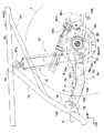
図4,5に示すように、フロントサスペンション60は、車体フレーム4のフロント部4aに支持されるもので、所謂ダブルウィッシュボーン型として構成される。すなわち、フロントサスペンション60は、車体フレーム4に基端側が上下に揺動自在に支持される左右のアッパアーム61及びロアアーム62と、各アッパアーム61及びロアアーム62の先端側にそれぞれ支持される左右のナックル63と、各ロアアーム62と車体フレーム4との間にそれぞれ介設される左右のフロントクッションユニット64とを主としてなる。  As shown in FIGS. 4 and 5, thefront suspension 60 is supported by thefront portion 4 a of thevehicle body frame 4 and is configured as a so-called double wishbone type. That is, thefront suspension 60 includes left and rightupper arms 61 andlower arms 62 that are supported by thevehicle body frame 4 so that the base end side thereof is swingable up and down, and left andright knuckles 63 that are respectively supported at the distal ends of theupper arms 61 and thelower arms 62. The left and rightfront cushion units 64 interposed between thelower arms 62 and thevehicle body frame 4 are mainly used.

各アッパアーム61及びロアアーム62は、その上面視で各ナックル63側(先端側)から車体フレーム4側(基端側)に向けて分岐する略V字形をなすもので、これらの各分岐側端部には、後下がりに傾斜する短いパイプ状のフレーム連結部61a,62aがそれぞれ一体的に設けられる。各フレーム連結部61a,62aは、互いに平行になるように、かつ各アッパアーム61及びロアアーム62毎に中心軸線を共有するように設けられている。  Each of theupper arms 61 and thelower arms 62 has a substantially V-shape that branches from theknuckle 63 side (front end side) toward thevehicle body frame 4 side (base end side) when viewed from above. Are integrally provided with short pipe-shapedframe connecting portions 61a and 62a that incline downward. Theframe connecting portions 61 a and 62 a are provided so as to be parallel to each other and share a central axis line for each of theupper arm 61 and thelower arm 62.

一方、中段前側及び後側クロスビーム51,52の両側部には、各アッパアーム61の前後のフレーム連結部61aに対応するアーム連結部51a,52aがそれぞれ設けられる。同様に、下段前側及び後側クロスビーム53,54の両側部には、各ロアアーム62の前後のフレーム連結部62aに対応するアーム連結部53a,54aがそれぞれ設けられる。  On the other hand,arm connecting portions 51 a and 52 a corresponding to theframe connecting portions 61 a before and after eachupper arm 61 are provided on both side portions of the middle front side and rear cross beams 51 and 52, respectively. Similarly,arm connecting portions 53 a and 54 a corresponding to theframe connecting portions 62 a before and after eachlower arm 62 are provided on both sides of the lower front and rear cross beams 53 and 54, respectively.

各アーム連結部51a〜54aには、対応するアッパアーム61又はロアアーム62のフレーム連結部61a,62aが、これらを前記中心軸線に沿って貫通する揺動軸(例えば段付きボルト)を用いて連結される。この状態で、各アーム連結部51a〜54aに各フレーム連結部61a,62aが揺動軸及びその外周に配されたベアリングを介して回転自在に支持される。すなわち、車体フレーム4のフロント部4aにアッパアーム61及びロアアーム62が揺動自在に支持されるのである。  Eacharm connecting portion 51a to 54a is connected to a correspondingupper arm 61 orframe connecting portion 61a or 62a of thelower arm 62 using a swing shaft (for example, a stepped bolt) penetrating thearm connecting portions 51a to 54a along the central axis. The In this state, theframe connecting portions 61a and 62a are rotatably supported by thearm connecting portions 51a to 54a via the swinging shaft and bearings arranged on the outer periphery thereof. That is, theupper arm 61 and thelower arm 62 are swingably supported by thefront portion 4a of thevehicle body frame 4.

各アッパアーム61及びロアアーム62の先端部には、ボールジョイント61b,62bを介して各ナックル63の上部又は下部がそれぞれ連結される。該各ナックル63には、同側の前輪2のハブ部2aが回転自在に支持されている。なお、各ナックル63の外側であって前輪2のホイール内には、該前輪用ブレーキとしてのディスクブレーキユニット2bが配設されている。  The upper or lower portion of eachknuckle 63 is connected to the tip of eachupper arm 61 andlower arm 62 via ball joints 61b and 62b. Eachknuckle 63 rotatably supports ahub portion 2a of thefront wheel 2 on the same side. Adisc brake unit 2b as a front wheel brake is disposed outside eachknuckle 63 and in thefront wheel 2 wheel.

各アッパアーム61の後部には、上方に向けて突出するアーム側マウント61cがそれぞれ設けられる。該各アーム側マウント61cには、同側のフロントクッションユニット64の下端部が、これらを前記中心軸線と平行に貫通する連結軸(例えば段付きボルト)を用いて連結される。この状態で、各アーム側マウント61cすなわちアッパアーム61に、各フロントクッションユニット64の下端部が、該下端部に内装されたベアリング及び連結軸を介して支持される。  At the rear part of eachupper arm 61, an arm-side mount 61c that protrudes upward is provided. Each arm-side mount 61c is connected to the lower end portion of thefront cushion unit 64 on the same side using a connecting shaft (for example, a stepped bolt) that passes through the arm-side mount 61c in parallel with the central axis. In this state, the lower end portion of eachfront cushion unit 64 is supported by each arm-side mount 61c, that is, theupper arm 61, via a bearing and a connecting shaft provided in the lower end portion.

また、上段中央クロスビーム55の両側部には、フレーム側マウント55aがそれぞれ設けられる。該フレーム側マウント55aには、同側のフロントクッションユニット64の上端部が、これらを前記中心軸線と平行に貫通する連結軸(例えば段付きボルト)を用いて連結される。この状態で、各フレーム側マウント55aすなわち車体フレーム4に、各フロントクッションユニット64の上端部が、該上端部に内装されたベアリング及び連結軸を介して支持される。  Further, frame side mounts 55 a are respectively provided on both sides of the uppermiddle cross beam 55. The upper end of thefront cushion unit 64 on the same side is connected to theframe side mount 55a by using a connecting shaft (for example, a stepped bolt) that passes through theframe side mount 55a in parallel with the central axis. In this state, the upper ends of thefront cushion units 64 are supported by the frame-side mounts 55a, that is, thevehicle body frame 4, via bearings and connecting shafts built in the upper ends.

このような構成により、各前輪2に路面からの衝撃荷重等が入力されると、これらが同側のアッパアーム61及びロアアーム62を介して個別に上下に揺動してフロントクッションユニット64を伸縮させ、該フロントクッションユニット64の緩衝作用により前記荷重が穏やかに吸収される。  With such a configuration, when an impact load or the like from the road surface is input to eachfront wheel 2, they individually swing up and down via theupper arm 61 and thelower arm 62 on the same side to expand and contract thefront cushion unit 64. The load is gently absorbed by the cushioning action of thefront cushion unit 64.

車体フレーム4のフロント部4aの略中央部には、前ファイナルリダクションギヤユニット13のケーシング13aがボルト等を用いて一体的に結合され、該前ファイナルリダクションギヤユニット13の入力部13bには、前ドライブシャフト11の前端部が結合される。該前ファイナルリダクションギヤユニット13は、前ドライブシャフト11の駆動力の回転方向を変換すると共に、左右の前輪2への駆動力配分を調整する差動機構としても機能するものである。  Acasing 13a of the front finalreduction gear unit 13 is integrally coupled to a substantially central portion of thefront portion 4a of thevehicle body frame 4 using bolts or the like, and aninput portion 13b of the front finalreduction gear unit 13 is connected to thefront portion 13b. The front end portion of thedrive shaft 11 is coupled. The front finalreduction gear unit 13 functions as a differential mechanism that converts the rotational direction of the driving force of thefront drive shaft 11 and adjusts the distribution of the driving force to the left and rightfront wheels 2.

前ファイナルリダクションギヤユニット13の外側方には左右の内自在継ぎ手15aがそれぞれ配置され、該各内自在継ぎ手15aから延びる接続ロッドが前ファイナルリダクションギヤユニット13の左右の出力部13cにそれぞれ結合される。一方、各ナックル63の内側方には左右の外自在継ぎ手15bがそれぞれ配置され、該各外自在継ぎ手15bから延びる接続ロッドが各前輪2のハブ部2aにそれぞれ結合される。  Left and right inneruniversal joints 15a are respectively arranged on the outer sides of the front finalreduction gear unit 13, and connecting rods extending from the inneruniversal joints 15a are respectively coupled to the left andright output portions 13c of the front finalreduction gear unit 13. . On the other hand, left and rightouter joints 15b are respectively arranged on the inner sides of theknuckles 63, and connecting rods extending from theouter joints 15b are coupled to thehub portions 2a of thefront wheels 2, respectively.

各内自在継ぎ手15aと外自在継ぎ手15bとの間には、左右のドライブシャフト15がそれぞれ渡設される。すなわち、各ドライブシャフト15は、その内側端部が同側の内自在継ぎ手15aを介して前ファイナルリダクションギヤユニット13の出力部13cにそれぞれ連結されると共に、外側端部が外自在継ぎ手15bを介して各前輪2のハブ部2aにそれぞれ連結される。  The left andright drive shafts 15 are respectively provided between the inneruniversal joints 15a and the outeruniversal joints 15b. That is, the inner end of eachdrive shaft 15 is connected to theoutput portion 13c of the front finalreduction gear unit 13 via the inner joint 15a on the same side, and the outer end is connected via the outer joint 15b. Are connected to thehub portions 2a of thefront wheels 2, respectively.

そして、前出力軸8に出力されたエンジン5の駆動力は、前ドライブシャフト11、前ファイナルリダクションギヤユニット13、各内自在継ぎ手15a、各ドライブシャフト15、及び各外自在継ぎ手15bを介して、各前輪2にそれぞれ伝達される。  The driving force of the engine 5 output to the front output shaft 8 is transmitted through thefront drive shaft 11, the front finalreduction gear unit 13, each inner universal joint 15a, each driveshaft 15, and each outer universal joint 15b. Each is transmitted to eachfront wheel 2.

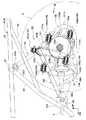
図6,7に示すように、各後輪3を懸架するリアサスペンション70は、スイングアーム71及びリアクッションユニット72を主として構成される。スイングアーム71は、その前端部が各ピボットブラケット49に上下に揺動自在に支持される一方、その後端部において各後輪3のハブ部3a間に渡るリアアクスルシャフト16を回転自在に支持するものである。このようなスイングアーム71は、その前端部を除く大部分が両後輪3間に位置するように設けられる。  As shown in FIGS. 6 and 7, therear suspension 70 that suspends eachrear wheel 3 mainly includes aswing arm 71 and arear cushion unit 72. Theswing arm 71 has a front end supported by eachpivot bracket 49 so as to be swingable up and down, and a rear end rotatably supporting therear axle shaft 16 extending between thehub portions 3a of therear wheels 3. Is. Such aswing arm 71 is provided so that most of theswing arm 71 is positioned between the tworear wheels 3 except for the front end portion thereof.

スイングアーム71の後端部近傍には、車体左右略中央において上方に位置するほど前方に位置するように傾斜して配されるリアクッションユニット72の下端部が連結される。また、該リアクッションユニット72の上端部は、車体フレーム4におけるリアクロスパイプ57に連結されている。このような構成により、各後輪3に路面からの衝撃荷重等が入力されると、両後輪3がスイングアーム71を介して上下に揺動してリアクッションユニット72を伸縮させ、該リアクッションユニット72の緩衝作用により前記荷重が穏やかに吸収される。  Near the rear end portion of theswing arm 71, a lower end portion of arear cushion unit 72 is connected so as to be inclined so as to be positioned forward in the approximate center of the left and right of the vehicle body. The upper end of therear cushion unit 72 is connected to therear cross pipe 57 in thevehicle body frame 4. With this configuration, when an impact load or the like from the road surface is input to eachrear wheel 3, bothrear wheels 3 swing up and down via theswing arm 71 to expand and contract therear cushion unit 72. The load is gently absorbed by the cushioning action of thecushion unit 72.

スイングアーム71は、前後に延設される左右のアーム体73と、これらに渡るクロスメンバ74と、各アーム体73の前端部にそれぞれ設けられる左右のピボット連結部75と、各アーム体73の後端部にそれぞれ設けられる左右の支持プレート76とを有し、これらが溶接等により一体的に結合されてなる。このようなスイングアーム71は、車体中心に対して概ね左右対称に設けられている。  Theswing arm 71 includes left andright arm bodies 73 extending in the front-rear direction, across member 74 extending over them, left and rightpivot connecting portions 75 respectively provided at the front end portions of thearm bodies 73, and thearm bodies 73. The left andright support plates 76 are provided at the rear end portions, and these are integrally coupled by welding or the like. Such aswing arm 71 is provided substantially symmetrically with respect to the center of the vehicle body.

各アーム体73は、その前後方向略中央部において下方に向けて凸状となるように屈曲形成されると共に、前端部が側面視で先細りとなるようにテーパ状に形成され、かつ後端部が上面視で先細りとなるように比較的緩やかなテーパ状に形成される。このような各アーム体73は、後方に位置するほど相互間の距離を減少させるように車体上面視でやや傾斜して配置されている。  Eacharm body 73 is bent so as to be convex downward at a substantially central portion in the front-rear direction, and is tapered so that the front end portion is tapered in a side view, and the rear end portion Is formed in a relatively gentle taper shape so as to be tapered in a top view. Each of thearm bodies 73 is arranged with a slight inclination when viewed from the top of the vehicle body so as to decrease the distance between thearm bodies 73 as it is located rearward.

各ピボット連結部75は、左右方向に沿う短いパイプ状のもので、該各ピボット連結部75の後部に同側のアーム体73の前端部がそれぞれ接合される。
各支持プレート76は、車体側面に沿う厚板状のもので、その前部には各アーム体73の後端部を挟み込むように上下一対の突出部76aが設けられ、該前部に同側のアーム体73の後端部が嵌まり込んだ状態でそれぞれ接合される。また、各支持プレート76の後部には、前記リアアクスルシャフト16を支持するべく、後方に向けて開放する略コの字形の支持部76bがそれぞれ設けられる。
Eachpivot connecting portion 75 is a short pipe-shaped member along the left-right direction, and the front end portion of thearm body 73 on the same side is joined to the rear portion of eachpivot connecting portion 75.
Eachsupport plate 76 has a plate-like shape along the side of the vehicle body, and a pair of upper andlower protrusions 76a are provided at the front part so as to sandwich the rear end part of eacharm body 73, and the front part is on the same side. Thearm bodies 73 are joined in a state where the rear end portions thereof are fitted. Further, at the rear part of eachsupport plate 76, a substantiallyU-shaped support part 76 b that opens rearward is provided to support therear axle shaft 16.

クロスメンバ74は、左右方向に沿って概ね直線的に延びるもので、両アーム体73の屈曲部間に渡設されている。該クロスメンバ74の両側部は、その上面視で末広がりとなるようにテーパ状に形成され、該両側部と各アーム体73との接合長さを稼ぐと共に応力集中を緩和させている。  Thecross member 74 extends substantially linearly along the left-right direction, and is provided between the bent portions of botharm bodies 73. Both side portions of thecross member 74 are formed in a tapered shape so as to widen toward the top as viewed from above, thereby increasing the joining length between the both side portions and eacharm body 73 and relaxing the stress concentration.

このようなクロスメンバ74は、車体側面視で各アーム体73の下側部に沿う円弧状断面を有するプレート部材77と、同じく車体側面視で上方に向けて凸状の略ハット形断面を有するハット形部材78とを有し、該ハット形部材78の前後の下辺部78aがプレート部材77に上方から重合した状態でこれらが溶接により一体的に結合されてなる。  Such across member 74 has aplate member 77 having an arc-shaped cross section along the lower side of eacharm body 73 in a side view of the vehicle body, and a substantially hat-shaped cross section that is convex upward in the same manner as viewed from the side of the vehicle body. A hat-shapedmember 78 is formed, and thelower sides 78a of the front and rear of the hat-shapedmember 78 are integrally joined to theplate member 77 by welding in a state where they are overlapped from above.

ハット形部材78の上辺部78bと各下辺部78aとに渡る前後の立壁部78cは、下方(プレート部材77側)に位置するほど相互間の距離を増加させるように傾斜して設けられる。また、プレート部材77の前後幅は、ハット形部材78の前後幅よりも幅広とされる。これにより、クロスメンバ74の底部(プレート部材77)の前後幅が、その上部(ハット形部材78の上辺部78b)の前後幅よりも十分幅広とされると共に、クロスメンバ74内に断面略台形状の内部空間部が形成される。  The front and rear standingwall portions 78c across theupper side portion 78b and thelower side portions 78a of the hat-shapedmember 78 are provided so as to be inclined so as to increase the distance between them as they are positioned downward (on theplate member 77 side). Further, the front-rear width of theplate member 77 is wider than the front-rear width of the hat-shapedmember 78. As a result, the front-rear width of the bottom portion (plate member 77) of thecross member 74 is sufficiently wider than the front-rear width of the upper portion (theupper side portion 78b of the hat-shaped member 78). A shaped internal space is formed.

しかも、クロスメンバ74は、車体側面視において、その底部が各アーム体73の下側部に沿って設けられると共に、上部が各アーム体73の上側部よりも下方に位置するように設けられる。すなわち、クロスメンバ74の上下幅が、各アーム体73の上下幅よりも狭くなるように設定されており、したがってクロスメンバ74は、車体側面視において、各アーム体73の上下から突出しないようになっている。  In addition, thecross member 74 is provided such that its bottom portion is provided along the lower side portion of eacharm body 73 and its upper portion is positioned below the upper side portion of eacharm body 73 in a side view of the vehicle body. That is, the vertical width of thecross member 74 is set to be narrower than the vertical width of eacharm body 73, and therefore thecross member 74 does not protrude from the top and bottom of eacharm body 73 in a side view of the vehicle body. It has become.

ここで、車体側面視でスイングアーム71のピボット中心とリアアクスルシャフト16の軸中心とを結んだ線をアーム基準線Kとすると、クロスメンバ74は、アーム基準線Kに対して下方にオフセットして設けられる。またここで、前記後ドライブシャフト12は、その中心軸線が車体側面視でアーム基準線Kと重なるように配されている。したがって後ドライブシャフト12とクロスメンバ74との間には、上下方向で十分なクリアランスが確保されている。  Here, when the line connecting the pivot center of theswing arm 71 and the axis center of therear axle shaft 16 is the arm reference line K in a side view of the vehicle body, thecross member 74 is offset downward with respect to the arm reference line K. Provided. Here, therear drive shaft 12 is arranged so that the central axis thereof overlaps the arm reference line K in a side view of the vehicle body. Therefore, a sufficient clearance is secured between therear drive shaft 12 and thecross member 74 in the vertical direction.

各ピボット連結部75は、同側のピボットブラケット49に対して、これらを左右方向に沿って貫通するピボット軸(例えば段付きボルト)を用いて連結される。この状態で、各ピボットブラケット49に各ピボット連結部75がピボット軸及びその外周に配されたベアリングを介して回転自在に支持される。すなわち、車体フレーム4にスイングアーム71の前端部が揺動自在に支持されるのである。  Eachpivot connecting portion 75 is connected to thepivot bracket 49 on the same side by using a pivot shaft (for example, a stepped bolt) that penetrates thepivot connecting portion 75 along the left-right direction. In this state, eachpivot connecting portion 75 is rotatably supported by eachpivot bracket 49 via a pivot shaft and a bearing disposed on the outer periphery thereof. That is, the front end portion of theswing arm 71 is swingably supported by thebody frame 4.

左側の支持プレート76には、後ドライブシャフト12からの駆動力をリアアクスルシャフト16の駆動力に変換する後ファイナルリダクションギヤユニット14が取り付けられる。一方、右側の支持プレート76には、後輪用ブレーキとしてのドラムブレーキユニット81が取り付けられる。これら後ファイナルリダクションギヤユニット14及びドラムブレーキユニット81を介して、スイングアーム71の後端部にリアアクスルシャフト16が回転自在に支持されている。  A rear finalreduction gear unit 14 that converts the driving force from therear drive shaft 12 into the driving force of therear axle shaft 16 is attached to theleft support plate 76. On the other hand, adrum brake unit 81 as a rear wheel brake is attached to theright support plate 76. Therear axle shaft 16 is rotatably supported at the rear end portion of theswing arm 71 through the rear finalreduction gear unit 14 and thedrum brake unit 81.

後ファイナルリダクションギヤユニット14は、エンジン5の後出力軸9に対応して車体左側にオフセットして設けられる。後出力軸9の後端部には、後ドライブシャフト12の前端部が自在継ぎ手12aを介して連結される。ここで、自在継ぎ手12aは、その可動中心がピボット中心上に位置するよう設けられる。後ドライブシャフト12の後端部は、後ファイナルリダクションギヤユニット14における入力側のベベルギヤ14bに結合される。  The rear finalreduction gear unit 14 is provided offset to the left side of the vehicle body corresponding to therear output shaft 9 of the engine 5. A front end portion of therear drive shaft 12 is connected to a rear end portion of therear output shaft 9 via a universal joint 12a. Here, the universal joint 12a is provided such that the movable center thereof is located on the pivot center. The rear end of therear drive shaft 12 is coupled to the inputside bevel gear 14 b in the rear finalreduction gear unit 14.

ベベルギヤ14bは、これに噛み合う大径ベベルギヤ14cと共に、後ファイナルリダクションギヤユニット14のケーシング14a内において回転自在に支持されている。大径ベベルギヤ14cはリアアクスルシャフト16と同軸配置されており、該大径ベベルギヤ14cのハブ部がこれを貫通するリアアクスルシャフト16にスプライン嵌合により結合される。  Thebevel gear 14b is rotatably supported in thecasing 14a of the rear finalreduction gear unit 14 together with the large-diameter bevel gear 14c meshing with thebevel gear 14b. The large-diameter bevel gear 14c is coaxially arranged with therear axle shaft 16, and the hub portion of the large-diameter bevel gear 14c is coupled to therear axle shaft 16 passing therethrough by spline fitting.

ケーシング14aは、その左側面を支持プレート76の右側面に当接させるようにしてこれにボルト等により一体的に結合される。これにより、左アーム体73の後端部にリアアクスルシャフト16が後ファイナルリダクションギヤユニット14を介して回転自在に支持される。
そして、後出力軸9に出力されたエンジン5の駆動力は、自在継ぎ手12a、後ドライブシャフト12、後ファイナルリダクションギヤユニット14、及びリアアクスルシャフト16を介して、各後輪3にそれぞれ伝達される。
Thecasing 14a is integrally coupled to the right side surface of thesupport plate 76 by bolts or the like so that the left side surface thereof is in contact with the right side surface of thesupport plate 76. Thus, therear axle shaft 16 is rotatably supported at the rear end portion of theleft arm body 73 via the rear finalreduction gear unit 14.
The driving force of the engine 5 output to therear output shaft 9 is transmitted to eachrear wheel 3 via the universal joint 12a, therear drive shaft 12, the rear finalreduction gear unit 14, and therear axle shaft 16. The

ドラムブレーキユニット81は、左方に向けて開口するブレーキドラム82と、該ブレーキドラム82の左側に対向配置されるブレーキベース83とを有する。
ブレーキドラム82はリアアクスルシャフト16と同軸配置されており、該ブレーキドラム82のハブ部がこれを貫通するリアアクスルシャフト16にスプライン嵌合により結合される。
Thedrum brake unit 81 includes abrake drum 82 that opens toward the left side, and abrake base 83 that is disposed to face the left side of thebrake drum 82.
Thebrake drum 82 is coaxially arranged with therear axle shaft 16, and the hub portion of thebrake drum 82 is coupled to therear axle shaft 16 passing therethrough by spline fitting.

また、ブレーキベース83は、その左側面を支持プレート76の右側面に当接させるようにしてこれにボルト等により一体的に結合される。また、ブレーキベース83は、そのハブ部を貫通するリアアクスルシャフト16にボールベアリング83aを介して回転自在に支持されている。  Further, thebrake base 83 is integrally coupled to the right side surface of thesupport plate 76 with a bolt or the like so that the left side surface thereof is in contact with the right side surface of thesupport plate 76. Thebrake base 83 is rotatably supported by arear axle shaft 16 penetrating the hub portion via aball bearing 83a.

ブレーキベース83には、一対のブレーキシュー84がブレーキドラム82の内周に摩擦接触し得るように支持される。すなわち、ブレーキベース83には、各ブレーキシュー84の支軸となるアンカーピン84aが立設されると共に、各ブレーキシュー84を拡開作動させるカム軸84bが回動自在に支持され、該カム軸84bの先端部には作動レバー84cがセレーション嵌合により取り付けられ、該作動レバー84cが、不図示のブレーキ操作子の操作によりケーブル84dを介して作動することで、カム軸84bが回動し各ブレーキシュー84が拡開してブレーキドラム82の内周に摩擦接触する。  A pair ofbrake shoes 84 are supported on thebrake base 83 so as to be in frictional contact with the inner periphery of thebrake drum 82. That is, ananchor pin 84a serving as a support shaft for eachbrake shoe 84 is provided upright on thebrake base 83, and acam shaft 84b for expanding thebrake shoe 84 is rotatably supported. An operatinglever 84c is attached to the distal end of 84b by serration fitting, and the operatinglever 84c is operated via acable 84d by operation of a brake operator (not shown), whereby thecam shaft 84b is rotated and each Thebrake shoe 84 expands and makes frictional contact with the inner periphery of thebrake drum 82.

ボールベアリング83aのインナレースの左側面には、リアアクスルシャフト16の外周に形成された環状突部16aの右側面が当接すると共に、該インナレースの右側面には、ブレーキドラム82のハブ部の左側面が当接するようになっている。リアアクスルシャフト16におけるドラムブレーキユニット81の右端近傍となる部位は、その外周にネジ山が刻設されたネジ部16bとされ、該ネジ部16bに二つのナット16cを螺着しドラムブレーキユニット81をダブルナット固定することで、スイングアーム71(右アーム体73)に対するドラムブレーキユニット81及びリアアクスルシャフト16の左右方向での位置が規制される。  The right side surface of theannular protrusion 16a formed on the outer periphery of therear axle shaft 16 contacts the left side surface of the inner race of theball bearing 83a, and the hub portion of thebrake drum 82 is formed on the right side surface of the inner race. The left side is in contact. A portion of therear axle shaft 16 near the right end of thedrum brake unit 81 is ascrew portion 16b having a thread formed on the outer periphery thereof, and twonuts 16c are screwed to thescrew portion 16b and thedrum brake unit 81 is screwed. Is fixed to the double nut so that the positions of thedrum brake unit 81 and therear axle shaft 16 in the left-right direction with respect to the swing arm 71 (right arm body 73) are regulated.

ドラムブレーキユニット81と後ファイナルリダクションギヤユニット14との間には、左右方向に沿う円筒状のアクスルハウジング85が配置される。該アクスルハウジング85は、その内部にリアアクスルシャフト16を挿通させるもので、その左端フランジ部が、その左側面を後ファイナルリダクションギヤユニット14のケーシング14aの右側面に当接させてこれにボルト等により一体的に結合される。また、アクスルハウジング85は、その右端フランジ部が、その右側面をドラムブレーキユニット81のブレーキベース83の左側面に当接するようになっている。すなわちアクスルハウジング85は、ドラムブレーキユニット81と後ファイナルリダクションギヤユニット14との間のディスタンスカラーとしても機能している。  Acylindrical axle housing 85 is disposed between thedrum brake unit 81 and the rear finalreduction gear unit 14 along the left-right direction. Theaxle housing 85 has arear axle shaft 16 inserted therethrough, and its left end flange portion abuts the left side surface thereof on the right side surface of thecasing 14a of the rear finalreduction gear unit 14, and a bolt or the like. Are integrally coupled. Further, the right end flange portion of theaxle housing 85 comes into contact with the left side surface of thebrake base 83 of thedrum brake unit 81. In other words, theaxle housing 85 also functions as a distance collar between thedrum brake unit 81 and the rear finalreduction gear unit 14.

アクスルハウジング85の左右方向略中央部には、斜め下前方に向けて突出するロアマウント85aが設けられる。該ロアマウント85aには、リアクッションユニット72の下端部が、これらを左右方向に沿って貫通する連結軸(例えば段付きボルト)を用いて連結される。一方、該リアクッションユニット72の上端部は、車体フレーム4のリアクロスパイプ57の左右方向略中央部に設けられたアッパマウント(リアクッション支持部)57a(図9参照)に、同じく左右方向に沿う連結軸(例えば段付きボルト)を用いて連結される。なお、アクスルハウジング85の左右方向略中央部には、後方に延びるマウントブラケット85b及びこれに支持されるヒッチボール85cを主として所謂トレーラヒッチが構成される。  Alower mount 85a that protrudes obliquely downward and forward is provided at a substantially central portion in the left-right direction of theaxle housing 85. Thelower mount 85a is connected to the lower end of therear cushion unit 72 using a connecting shaft (for example, a stepped bolt) that passes through thelower cushion unit 72 along the left-right direction. On the other hand, the upper end portion of therear cushion unit 72 is connected to the upper mount (rear cushion support portion) 57a (see FIG. 9) provided in the substantially central portion of therear cross pipe 57 of thevehicle body frame 4 in the left-right direction. It connects using the connecting shaft which follows (for example, a bolt with a step). Theaxle housing 85 has a so-called trailer hitch that is mainly composed of a mountingbracket 85b extending backward and a hitch ball 85c supported by the mountingbracket 85b.

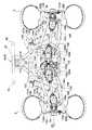
ここで、図8,9に示すように、鞍乗り型四輪車1においては、前記スイングアーム式のリアサスペンション70に代わり、独立懸架式のリアサスペンション130を設けることが可能とされている。  As shown in FIGS. 8 and 9, in the saddle-ride type four-wheel vehicle 1, an independent suspension typerear suspension 130 can be provided instead of the swing arm typerear suspension 70.

リアサスペンション130は、車体フレーム4に一体的に取り付けられるサブフレームアッシ140に支持されるもので、所謂ダブルウィッシュボーン型として構成される。すなわち、リアサスペンション130は、サブフレームアッシ140に基端側が上下に揺動自在に支持される左右のアッパアーム131及びロアアーム132と、各アッパアーム131及びロアアーム132の先端側にそれぞれ支持される左右のナックル133と、各ロアアーム132とサブフレームアッシ140との間にそれぞれ介設される左右のリアクッションユニット134とを主としてなる。  Therear suspension 130 is supported by asubframe assembly 140 that is integrally attached to thevehicle body frame 4 and is configured as a so-called double wishbone type. That is, therear suspension 130 includes left and rightupper arms 131 andlower arms 132 whose base end sides are swingably supported by thesubframe assembly 140, and left and right knuckles supported by distal ends of theupper arms 131 and thelower arms 132, respectively. 133 and the left and rightrear cushion units 134 respectively interposed between thelower arms 132 and thesubframe assembly 140 are mainly used.

図10,11を併せて参照して説明すると、サブフレームアッシ140は、車体側面視において前方に向けて開放するように湾曲する左右のリアクッションパイプ141と、該各リアクッションパイプ141の下部先端部に渡るように設けられ両側が斜め上前方に向けて湾曲するリアクッションロアパイプ148と、該リアクッションロアパイプ148の両湾曲端部と各リアクッションパイプ141の上部とに渡るように設けられる左右のリアクッションサブパイプ142と、各リアクッションパイプ141及びリアクッションサブパイプ142間に渡設される複数のクロスビーム143,144,146,147とを有し、これらが溶接等により一体的に結合されてなる。このようなサブフレームアッシ140は、車体左右中心に対して概ね左右対称に設けられ、かつその大部分が両後輪間に位置するように設けられる。  10 and 11, thesubframe assembly 140 includes left and rightrear cushion pipes 141 that are curved to open forward in a side view of the vehicle body, and lower tips of therear cushion pipes 141. The rear cushionlower pipe 148 that is provided so as to cross over the both sides and curves on both sides obliquely upward and forward, and is provided so as to cross over both curved ends of the rear cushionlower pipe 148 and the upper part of eachrear cushion pipe 141. The left and right rearcushion sub pipes 142 and a plurality of cross beams 143, 144, 146, 147 provided between therear cushion pipes 141 and the rearcushion sub pipes 142 are integrally formed by welding or the like. Combined. Such asub-frame assembly 140 is provided substantially symmetrically with respect to the left-right center of the vehicle body, and most of thesub-frame assembly 140 is provided between both rear wheels.

各リアクッションパイプ141は、車体側面視において各後輪3のハブ部3aよりも下方となる位置にて略水平に配される下部水平部141aと、ハブ部3aよりも上方となる位置にて前上がりに傾斜して配される上部傾斜部141bと、これら下部水平部141a及び上部傾斜部141bの後端部をハブ部よりも後方となる位置にて接続する後方に向けて凸状の円弧状部141cとを、一本の鋼管に曲げ加工を施すことで一体に形成してなる。  Eachrear cushion pipe 141 has a lowerhorizontal portion 141a disposed substantially horizontally at a position below thehub portion 3a of eachrear wheel 3 in a side view of the vehicle body, and a position above thehub portion 3a. An upperinclined portion 141b arranged to be inclined forward and a rearward convex circle connecting the rear ends of the lowerhorizontal portion 141a and the upperinclined portion 141b at a position behind the hub portion. Thearcuate portion 141c is integrally formed by bending one steel pipe.

また、リアクッションロアパイプ148は、左右方向に沿う下部水平部148a及びその左右の湾曲部148bを、一本の鋼管に曲げ加工を施すことで一体に形成してなる。このようなリアクッションロアパイプ148の下部水平部148aの両端部近傍に、各リアクッションパイプ141の下部先端部がそれぞれ接合される。  The rear cushionlower pipe 148 is formed by integrally forming a lowerhorizontal portion 148a along the left-right direction and left and rightcurved portions 148b by bending a single steel pipe. In the vicinity of both end portions of the lowerhorizontal portion 148a of the rear cushionlower pipe 148, the lower end portions of therear cushion pipes 141 are respectively joined.

各リアクッションサブパイプ142は、車体側面視で前下がりに傾斜して配されるもので、一本の鋼管に曲げ加工を施すことで、その前部が後部よりも左右方向外側に位置するようクランク状に形成される。このような各リアクッションサブパイプ142の前端部近傍には、リアクッションロアパイプ148の両湾曲端部がそれぞれ接合されると共に、各リアクッションサブパイプ142の後端部は、リアクッションパイプ141の上部傾斜部141bの長手方向略中央部にそれぞれ接合される。  Eachrear cushion sub-pipe 142 is arranged so as to incline forward and downward as viewed from the side of the vehicle body. By bending one steel pipe, the front part is positioned on the outer side in the left-right direction with respect to the rear part. It is formed in a crank shape. In the vicinity of the front end of eachrear cushion sub-pipe 142, both curved ends of the rear cushionlower pipe 148 are joined, and the rear end of eachrear cushion sub-pipe 142 is connected to therear cushion pipe 141. The upperinclined portion 141b is joined to the substantially central portion in the longitudinal direction.

各リアクッションパイプ141の上部傾斜部141b間には、左右方向に沿って延びる上段中央クロスビーム147及び中段後側クロスビーム144がそれぞれ渡設される。以下同様に、各リアクッションパイプ141の下部水平部141a間には下段後側クロスビーム146が渡設され、各リアクッションサブパイプ142間には中段前側クロスビーム143が渡設される。  Between the upperinclined portion 141b of eachrear cushion pipe 141, an uppermiddle cross beam 147 and a middlerear cross beam 144 extending in the left-right direction are respectively provided. Similarly, a lowerrear cross beam 146 is provided between the lowerhorizontal portions 141 a of therear cushion pipes 141, and a middlefront cross beam 143 is provided between the rearcushion sub pipes 142.

各リアクッションパイプ141の上部傾斜部141bは、そのリアクッションサブパイプ142との結合部近傍で湾曲し、該結合部よりも上方となる部位を左右方向内側に向けて傾斜させるように設けられる。このような各上部傾斜部141bの先端部は、左右方向略中央にて合流して接合され、かつこれらに跨るように左右方向に沿う短いパイプ状の上部中央連結部141dが一体的に設けられる。
また、各リアクッションサブパイプ142の前端部には、左右方向に沿う短いパイプ状の左右のピボット連結部142aがそれぞれ一体的に設けられる。
The upperinclined portion 141b of eachrear cushion pipe 141 is provided so as to bend in the vicinity of the coupling portion with the rearcushion sub pipe 142 and to incline a portion above the coupling portion inward in the left-right direction. The tip portions of the upperinclined portions 141b are joined and joined at substantially the center in the left-right direction, and a short pipe-shaped uppercenter connecting portion 141d extending in the left-right direction is integrally provided so as to straddle them. .
Also, at the front end portion of eachrear cushion sub-pipe 142, a short pipe-like left and rightpivot connecting portion 142a extending in the left-right direction is integrally provided.

図8,9に示すように、各ピボット連結部142aは、車体フレーム4における同側のピボットブラケット49に対して、これらを貫通するボルト及びナットを用いてそれぞれ締結されると共に、上部中央連結部141dは、アッパマウント57aに対して、これらを貫通するボルト及びナットを用いて締結される。  As shown in FIGS. 8 and 9, eachpivot connecting portion 142a is fastened to thepivot bracket 49 on the same side of thevehicle body frame 4 using bolts and nuts penetrating them, and the upper central connecting portion. 141d is fastened to theupper mount 57a by using bolts and nuts penetrating them.

ここで、図12を参照して各ピボット連結部142aとピボットブラケット49との結合部について説明すると、各ピボットブラケット49は、一対の板状部材を左右方向で対向させるようにしてなるもので、該各板状部材間にピボット連結部142aが進入した状態で、これらが左右方向に沿うボルト及びナットを用いて締結される。なお、アッパマウント57aと上部中央連結部141dとの結合部も同様の構成を有するものとしてその説明は省略する。
このように、各ピボットブラケット49及びアッパマウント57aを利用して、車体フレーム4にサブフレームアッシ140が一体的に取り付けられる。
Here, with reference to FIG. 12, a description will be given of a joint portion between eachpivot connecting portion 142a and thepivot bracket 49. Eachpivot bracket 49 is configured to face a pair of plate-like members in the left-right direction. With thepivot connecting portion 142a entering between the plate-like members, these are fastened using bolts and nuts along the left-right direction. The connecting portion between theupper mount 57a and the upper central connectingportion 141d has the same configuration, and the description thereof is omitted.
In this manner, thesubframe assembly 140 is integrally attached to thevehicle body frame 4 using thepivot brackets 49 and theupper mounts 57a.

各アッパアーム131及びロアアーム132は、その上面視で各ナックル133側(先端側)からサブフレームアッシ140側(基端側)に向けて分岐する略V字形をなすもので、これらの各分岐側端部には、後下がりに傾斜する短いパイプ状のフレーム連結部131a,132aがそれぞれ一体的に設けられる。各フレーム連結部131a,132aは、互いに平行になるように、かつ各アッパアーム131及びロアアーム132毎に中心軸線を共有するように設けられている。  Each of theupper arm 131 and thelower arm 132 has a substantially V-shape that branches from theknuckle 133 side (front end side) toward thesubframe assembly 140 side (base end side) when viewed from above. Each part is integrally provided with a short pipe-shapedframe connecting portion 131a, 132a inclined downward. Theframe connecting portions 131a and 132a are provided so as to be parallel to each other and share the central axis line for each of theupper arm 131 and thelower arm 132.

一方、中段前側及び後側クロスビーム143,144の両側部には、各アッパアーム131の前後のフレーム連結部131aに対応するアーム連結部143a,144aがそれぞれ設けられる。また、下段後側クロスビーム146の両側部には、各ロアアーム132の後側のフレーム連結部132aに対応するアーム連結部146aがそれぞれ設けられる。さらに、各リアクッションパイプ141の上部傾斜部141bには、各ロアアーム132の前側のフレーム連結部132aに対応するアーム連結部145aを構成する下段前側支持ブラケット145がそれぞれ設けられる。  On the other hand,arm connecting portions 143a and 144a corresponding to the front and rearframe connecting portions 131a of theupper arms 131 are provided on both sides of the middle front and rear cross beams 143 and 144, respectively. Further, on both sides of the lowerrear cross beam 146,arm connection portions 146a corresponding to theframe connection portions 132a on the rear side of thelower arms 132 are provided. Furthermore, the lower inclinedfront support brackets 145 constituting thearm connecting portions 145a corresponding to the frontframe connecting portions 132a of the respectivelower arms 132 are provided on the upperinclined portions 141b of the respectiverear cushion pipes 141, respectively.

各アーム連結部143a〜146aには、対応するアッパアーム131又はロアアーム132のフレーム連結部131a,132aが、これらを前記中心軸線に沿って貫通する揺動軸(例えば段付きボルト)を用いて連結される。この状態で、各アーム連結部143a〜146aに各フレーム連結部131a,132aが揺動軸及びその外周に配されたベアリングを介して回転自在に支持される。すなわち、サブフレームアッシ140にアッパアーム131及びロアアーム132が揺動自在に支持されるのである。  Thearm connecting portions 143a to 146a are connected to the correspondingupper arm 131 or theframe connecting portions 131a and 132a of thelower arm 132 using swinging shafts (for example, stepped bolts) penetrating thearm connecting portions 143a to 146a along the central axis. The In this state, theframe connecting portions 131a and 132a are rotatably supported by thearm connecting portions 143a to 146a via the swing shaft and bearings arranged on the outer periphery thereof. That is, theupper arm 131 and thelower arm 132 are swingably supported by thesubframe assembly 140.

各アッパアーム131及びロアアーム132の先端部には、各フレーム連結部131a,132aと平行となるように後下がりに傾斜する短いパイプ状のナックル連結部131b,132bがそれぞれ一体的に設けられる。一方、各ナックル133の上部及び下部には、各アッパアーム131及びロアアーム132のナックル連結部131b,132bに対応するナックル側アーム連結部133aがそれぞれ設けられる。  Short pipe-shapedknuckle connecting portions 131b and 132b that incline rearwardly downward so as to be parallel to the respectiveframe connecting portions 131a and 132a are integrally provided at the distal ends of theupper arms 131 and thelower arms 132, respectively. On the other hand, knuckle-sidearm coupling portions 133a corresponding to theknuckle coupling portions 131b and 132b of theupper arms 131 and thelower arms 132 are provided at the upper and lower portions of theknuckle 133, respectively.

各ナックル側アーム連結部133aには、対応するアッパアーム131又はロアアーム132のナックル連結部131b,132bが、これらを前記中心軸線と平行に貫通する連結軸(例えば段付きボルト)を用いて連結される。この状態で、各ナックル連結部131b,132bすなわちアッパアーム131及びロアアーム132に、各ナックル側アーム連結部133aすなわちナックル133が、連結軸及びその外周に配されたベアリングを介して支持される。該各ナックル133には、同側の後輪3のハブ部が回転自在に支持されている。  Each knuckle-sidearm connecting portion 133a is connected to the correspondingupper arm 131 orknuckle connecting portion 131b or 132b of thelower arm 132 by using a connecting shaft (for example, a stepped bolt) that passes through them parallel to the central axis. . In this state, theknuckle connecting portions 131b and 132b, that is, theupper arm 131 and thelower arm 132, are supported by the knuckle sidearm connecting portions 133a, that is, theknuckle 133, via the connecting shaft and bearings arranged on the outer periphery thereof. Eachknuckle 133 rotatably supports the hub portion of therear wheel 3 on the same side.

各ロアアーム132の前部には、上方に向けて突出するアーム側マウント132cがそれぞれ設けられる。該各アーム側マウント132cには、同側のリアクッションユニット134の下端部が、これらを前記中心軸線と平行に貫通する連結軸(例えば段付きボルト)を用いて連結される。この状態で、各アーム側マウント132cすなわちロアアーム132に、各リアクッションユニット134の下端部が、該下端部に内装されたベアリング及び連結軸を介して支持される。  At the front part of eachlower arm 132, an arm-side mount 132c that protrudes upward is provided. The lower end portions of therear cushion units 134 on the same side are connected to the arm-side mounts 132c by using connection shafts (for example, stepped bolts) that pass through them in parallel with the central axis. In this state, the lower end portion of eachrear cushion unit 134 is supported on each arm-side mount 132c, that is, thelower arm 132 via a bearing and a connecting shaft that are built in the lower end portion.

また、上段中央クロスビーム147の両側部には、フレーム側マウント147aがそれぞれ設けられる。該フレーム側マウント147aには、同側のリアクッションユニット134の上端部が、これらを前記中心軸線と平行に貫通する連結軸(例えば段付きボルト)を用いて連結される。この状態で、各フレーム側マウント147aすなわち車体フレーム4に、各リアクッションユニット134の上端部が、該上端部に内装されたベアリング及び連結軸を介して支持される。  Further, frame-side mounts 147a are provided on both sides of the uppermiddle cross beam 147, respectively. An upper end portion of therear cushion unit 134 on the same side is connected to theframe side mount 147a by using a connecting shaft (for example, a stepped bolt) that passes through these in parallel with the central axis. In this state, the upper ends of therear cushion units 134 are supported by the frame-side mounts 147a, that is, thevehicle body frame 4, via bearings and connecting shafts built in the upper ends.

このような構成により、各後輪3に路面からの衝撃荷重等が入力されると、これらが同側のアッパアーム131及びロアアーム132を介して個別に上下に揺動してリアクッションユニット134を伸縮させ、該リアクッションユニット134の緩衝作用により前記荷重が穏やかに吸収される。  With such a configuration, when an impact load or the like from the road surface is input to eachrear wheel 3, they individually swing up and down via theupper arm 131 and thelower arm 132 on the same side to expand and contract therear cushion unit 134. The load is gently absorbed by the buffering action of therear cushion unit 134.

サブフレームアッシ140の後部(詳細には左リアクッションパイプ141の後部)には、後ファイナルリダクションギヤユニット135のケーシング135aがボルト等を用いて一体的に結合される。該後ファイナルリダクションギヤユニット135は、その入力部135bが概ね車体左右略中央に位置するように設けられ、該入力部135bには、不図示の自在継ぎ手を介して後ドライブシャフト12の後端部が結合される。後ドライブシャフト12は、車体左側にオフセットした後出力軸9の後端部と車体左右略中央に位置する後ファイナルリダクションギヤユニット135の入力部135bとに渡るように傾斜して配される。なお、後ドライブシャフト12の後ファイナルリダクションギヤユニット135寄りの部位には、後輪用ブレーキのブレーキディスクが同軸固定されている。  Acasing 135a of the rear finalreduction gear unit 135 is integrally coupled to the rear portion of the subframe assembly 140 (specifically, the rear portion of the left rear cushion pipe 141) using bolts or the like. The rear finalreduction gear unit 135 is provided so that itsinput part 135b is located approximately at the center of the left and right of the vehicle body. The rear part of therear drive shaft 12 is connected to theinput part 135b via a universal joint (not shown). Are combined. Therear drive shaft 12 is disposed so as to incline across the rear end portion of therear output shaft 9 offset to the left side of the vehicle body and theinput portion 135b of the rear finalreduction gear unit 135 located substantially in the center of the left and right sides of the vehicle body. A brake disc for a rear wheel brake is coaxially fixed to a portion near the rear finalreduction gear unit 135 of therear drive shaft 12.

後ファイナルリダクションギヤユニット135の外側方には左右の内自在継ぎ手136aがそれぞれ配置され、該各内自在継ぎ手136aから延びる接続ロッドが後ファイナルリダクションギヤユニット135の左右の出力部135cにそれぞれ結合される。一方、各ナックル133の内側方には左右の外自在継ぎ手136bがそれぞれ配置され、該各外自在継ぎ手136bから延びる接続ロッドが各後輪3のハブ部3aにそれぞれ結合される。  Left and rightinner joints 136a are respectively arranged on the outer sides of the rear finalreduction gear unit 135, and connecting rods extending from the inneruniversal joints 136a are respectively coupled to the left andright output portions 135c of the rear finalreduction gear unit 135. . On the other hand, left and rightouter joints 136b are respectively arranged on the inner sides of theknuckles 133, and connecting rods extending from theouter joints 136b are coupled to thehub portions 3a of therear wheels 3, respectively.

各内自在継ぎ手136aと外自在継ぎ手136bとの間には、左右のドライブシャフト136がそれぞれ渡設される。すなわち、各ドライブシャフト136は、その内側端部が同側の内自在継ぎ手136aを介して後ファイナルリダクションギヤユニット135の出力部135cに連結されると共に、外側端部が外自在継ぎ手136bを介して各後輪3のハブ部3aにそれぞれ連結される。
そして、後出力軸9に出力されたエンジン5の駆動力は、自在継ぎ手12a、後ドライブシャフト12、後ファイナルリダクションギヤユニット135、各内自在継ぎ手136a、各ドライブシャフト136、及び各外自在継ぎ手136bを介して、各後輪3にそれぞれ伝達される。
Left andright drive shafts 136 are respectively provided between the inneruniversal joints 136a and the outeruniversal joints 136b. That is, eachdrive shaft 136 has an inner end connected to theoutput portion 135c of the rear finalreduction gear unit 135 via the inner flexible joint 136a, and an outer end connected via the outer universal joint 136b. Eachrear wheel 3 is connected to ahub portion 3a.
The driving force of the engine 5 output to therear output shaft 9 is the universal joint 12a, therear drive shaft 12, the rear finalreduction gear unit 135, each inner universal joint 136a, eachdrive shaft 136, and each outer universal joint 136b. Is transmitted to eachrear wheel 3 via.

以上説明したように、上記実施例におけるフレーム構造は、車体フレーム4が、各前輪2を懸架するフロント部4aと、エンジン5を支持するセンタ部4bと、シートレールを兼ねるリア部4cとを有してなり、前記センタ部4bには各後輪3を懸架するスイングアーム71が支持されると共に、該センタ部4bもしくはリア部4cにはリアクッションユニット72が支持されるものであって、前記センタ部4bに設けられた各ピボットブラケット49と、リアクロスパイプ57に設けられたアッパマウント57aとを利用して、車体フレーム4に独立懸架式リアサスペンション130用のサブフレームアッシ140を取り付け可能としたものである。  As described above, in the frame structure in the above embodiment, thevehicle body frame 4 has thefront part 4a for suspending eachfront wheel 2, thecenter part 4b for supporting the engine 5, and therear part 4c also serving as a seat rail. Thecenter portion 4b supports aswing arm 71 for suspending eachrear wheel 3, and thecenter portion 4b or therear portion 4c supports arear cushion unit 72, Thesubframe assembly 140 for the independent suspension typerear suspension 130 can be attached to thevehicle body frame 4 by using eachpivot bracket 49 provided in thecenter portion 4b and theupper mount 57a provided in therear cross pipe 57. It is a thing.

この構成によれば、スイングアーム式リアサスペンション70を採用する鞍乗り型四輪車1における車体フレーム4を、該鞍乗り型四輪車1が独立懸架式リアサスペンション130を採用する場合にも流用することが可能となる。すなわち、リアサスペンション形式の異なる車両間においても車体フレーム4を共用することができ、該車体フレーム4ひいては鞍乗り型四輪車1の大幅なコストダウンを図ることができる。
このとき、サブフレームアッシ140が、独立懸架式リアサスペンション130用のクッション取り付け部としてのフレーム側マウント147aを備えることで、車体フレーム4に予め独立懸架式リアサスペンション130用の部品を設けておく必要がなくなるため、車体フレーム4流用時の余剰部品の発生を抑えることができる。
According to this configuration, thevehicle body frame 4 in the saddle-ride type four-wheel vehicle 1 that employs the swing arm typerear suspension 70 can be used even when the saddle-ride type four-wheel vehicle 1 employs the independent suspension typerear suspension 130. It becomes possible to do. That is, thevehicle body frame 4 can be shared between vehicles of different rear suspension types, and the cost of thevehicle body frame 4 and thus the saddle-ride type four-wheel vehicle 1 can be greatly reduced.
At this time, thesubframe assembly 140 is provided with a frame-side mount 147a as a cushion mounting portion for the independent suspension typerear suspension 130, so that thebody frame 4 needs to be provided with parts for the independent suspension typerear suspension 130 in advance. Therefore, the generation of surplus parts when thebody frame 4 is used can be suppressed.

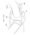
なお、この発明は上記実施例に限られるものではなく、例えば、図13に示すサブフレームアッシ150を用いてもよい。
すなわち、サブフレームアッシ150の各リアクッションパイプ141の後端部(円弧状部141c近傍)から上方に向けて支持パイプ151を延出し、該各支持パイプ151の上端部にはそれぞれ上部連結部151aを設ける一方、車体フレーム4における各リアアッパパイプ43とリアサブパイプ44との結合部近傍には各上部連結部151aに対応するサイドマウント151bをそれぞれ設け、これら各サイドマウント151bと上部連結部151aとをボルト等を用いて連結する構成としてもよい。ここで、各サイドマウント151b及び上部連結部151aは、アッパマウント57aよりも左右方向外側に位置している。なお、図13において、上記実施例と同一部分には同一符号を付してその説明は省略する。
Note that the present invention is not limited to the above embodiment, and for example, asubframe assembly 150 shown in FIG. 13 may be used.
That is, thesupport pipe 151 extends upward from the rear end portion (in the vicinity of thearcuate portion 141c) of eachrear cushion pipe 141 of thesubframe assembly 150, and theupper connection portion 151a is provided at the upper end portion of eachsupport pipe 151. On the other hand, side mounts 151b corresponding to the respective upper connectingportions 151a are provided in the vicinity of the connecting portions of the rearupper pipes 43 and therear sub pipes 44 in thevehicle body frame 4, and these side mounts 151b and the upper connectingportions 151a are provided. And may be connected using bolts or the like. Here, eachside mount 151b and the upper connectingportion 151a are located on the outer side in the left-right direction with respect to theupper mount 57a. In FIG. 13, the same parts as those in the above embodiment are denoted by the same reference numerals, and the description thereof is omitted.

このように、車体フレーム4における各ピボットブラケット49及びアッパマウント57aとは異なる部位に、サブフレームアッシ150を支持する各サイドマウント151bを設けることで、上記実施例における作用効果に加え、サブフレームアッシ150の車体フレーム4への取り付け剛性ひいてはリアサスペンション130の剛性を高めることができる。
またこのとき、車体フレーム4におけるアッパマウント57aよりも左右方向外側に位置する部位に、サブフレームアッシ150を支持するサイドマウント151bを設けることで、スイングアーム式リアサスペンション70用のアッパマウント57aが車体左右方向略中央部に設けられるような場合でも、サブフレームアッシ150の安定した取り付けが可能となる。
As described above, by providing the side mounts 151b for supporting thesubframe assembly 150 at portions different from thepivot brackets 49 and theupper mounts 57a in thevehicle body frame 4, in addition to the operational effects of the above embodiment, the subframe assembly The rigidity of mounting 150 on thevehicle body frame 4 and thus the rigidity of therear suspension 130 can be increased.
At this time, theside mount 151b that supports thesub-frame assembly 150 is provided in a portion of thevehicle body frame 4 that is located on the outer side in the left-right direction with respect to theupper mount 57a, so that theupper mount 57a for the swing arm typerear suspension 70 is mounted on the vehicle body. Even in the case where thesubframe assembly 150 is provided at the substantially central portion in the left-right direction, thesubframe assembly 150 can be stably attached.

そして、上記実施例における構成は一例であり、鞍乗り型四輪車への適用に限定されないことはもちろん、発明の要旨を逸脱しない範囲で種々の変更が可能であることはいうまでもない。  And the structure in the said Example is an example, and it cannot be overemphasized that a various change is possible in the range which does not deviate from the summary of invention, as well as being not limited to application to a saddle-ride type four-wheel vehicle.

この発明における鞍乗り型四輪車の側面図である。1 is a side view of a saddle-ride type four-wheel vehicle according to the present invention.上記鞍乗り型四輪車の上面図である。It is a top view of the saddle-ride type four-wheel vehicle.上記鞍乗り型四輪車の車体フレームの側面図である。It is a side view of the body frame of the saddle-ride type four-wheel vehicle.上記鞍乗り型四輪車のフロントサスペンションの側面図である。It is a side view of the front suspension of the saddle-ride type four-wheel vehicle.図4におけるA矢視図である。It is A arrow directional view in FIG.上記鞍乗り型四輪車のスイングアーム式リアサスペンションの側面図である。It is a side view of the swing arm type rear suspension of the saddle-ride type four-wheel vehicle.上記スイングアーム式リアサスペンションの上面説明図である。FIG. 3 is an explanatory top view of the swing arm type rear suspension.上記鞍乗り型四輪車の独立懸架式リアサスペンションの側面図である。It is a side view of the independent suspension type rear suspension of the saddle-ride type four-wheel vehicle.図8におけるB矢視図である。It is a B arrow view in FIG.上記独立懸架式リアサスペンション用のサブフレームアッシの側面図である。It is a side view of the sub-frame assembly for the said independent suspension type rear suspension.図10におけるC矢視図である。It is C arrow line view in FIG.ピボット連結部とピボットブラケットとの結合部を示す斜視図である。It is a perspective view which shows the coupling | bond part of a pivot connection part and a pivot bracket.上記サブフレームアッシの変形例を示す側面図である。It is a side view which shows the modification of the said sub-frame assembly.

符号の説明Explanation of symbols

2 前輪
3 後輪
4 車体フレーム
4a フロント部
4b センタ部
4c リア部
5 エンジン
49 ピボットブラケット(スイングアーム支持部)
57a アッパマウント(リアクッション支持部)
151b サイドマウント(支持部)
71 スイングアーム
72 リアクッションユニット(リアクッション)
140,150 サブフレームアッシ(サブフレーム)
147a フレーム側マウント(クッション取り付け部)

2Front wheel 3Rear wheel 4Body frame 4aFront part4b Center part 4c Rear part 5Engine 49 Pivot bracket (swing arm support part)
57a Upper mount (rear cushion support)
151b Side mount (support)
71Swing arm 72 Rear cushion unit (rear cushion)
140,150 Subframe assembly (subframe)
147a Frame side mount (cushion mounting part)

Claims (4)

Translated fromJapanese
輪を懸架するフロント部と、エンジンを支持するセンタ部と、シートレールを兼ねるリア部とを有する車体フレームを備え、スイングアーム式リアサスペンションと独立懸架式リアサスペンションとを変更して取付可能な鞍乗り型車両の車体フレームのリア部交換方法であって、
スイングアーム式リアサスペンションを独立懸架式リアサスペンションに変更する場合、
前記センタ部に設けられた、少なくとも二つの後輪を懸架するスイングアームが支持されるスイングアーム支持部と、前記センタ部もしくはリア部に設けられた、リアクッションが支持されるリアクッション支持部とを利用して、前記車体フレームに独立懸架式リアサスペンション用のサブフレームを取り付けることを特徴とする車体フレームのリア部交換方法
A front portion for suspending afront wheel, a center portion for supporting an engine,comprising a body frame which have a and a rear portion serving also as a seatrail, attachable by changing the independent suspension type rear suspension and a swing arm rear suspensionA rear part replacement method for abody frame ofa saddle-ride type vehicle,
When changing the swing arm type rear suspension to the independent suspension type rear suspension,
A swing arm support portion provided at the center portion forsupporting a swing arm for suspending at least two rear wheels;a rear cushion support portion provided at the center portion or the rear portion forsupporting a rear cushion; Amethod for replacing a rear portion of avehicle body frame, comprising attaching a sub-frame for an independent suspension type rear suspension to thevehicle body frameusing
前記サブフレームが、独立懸架式リアサスペンション用のクッション取り付け部を備えることを特徴とする請求項1に記載の車体フレームのリア部交換方法Themethod for replacing a rear portion of avehicle body frame according to claim 1, wherein the sub-frame includes a cushion mounting portion for an independent suspension type rear suspension. 前記車体フレームにおける前記スイングアーム支持部及びリアクッション支持部とは異なる部位に、前記サブフレーム用の支持部を設けたことを特徴とする請求項1又は請求項2に記載の車体フレームのリア部交換方法3.The rear portion of thevehicle body frame according to claim 1, wherein a support portion for the subframe is provided in a portion different from the swing arm support portion and the rear cushion support portion in thevehicle body frame. Exchange method . 前記車体フレームにおける前記リアクッション支持部よりも左右方向外側に位置する部位に、前記サブフレーム用の支持部を設けたことを特徴とする請求項3に記載の車体フレームのリア部交換方法4. Themethod for replacing a rear portion of avehicle body frame according to claim 3, wherein a support portion for the sub-frame is provided in a portion of thevehicle body frame that is located on the outer side in the left-right direction with respect to the rear cushion support portion.
JP2004289271A2004-09-302004-09-30 How to replace the rear part of the body frameExpired - Fee RelatedJP4271641B2 (en)

Priority Applications (11)

Application NumberPriority DateFiling DateTitle
JP2004289271AJP4271641B2 (en)2004-09-302004-09-30 How to replace the rear part of the body frame
AU2005203450AAU2005203450B2 (en)2004-09-302005-08-03Frame structure
BRPI0503634ABRPI0503634B1 (en)2004-09-302005-08-26 carcass structure
MYPI20054049AMY140545A (en)2004-09-302005-08-29Frame structure.
CNB2005100938272ACN100465051C (en)2004-09-302005-08-30Frame structure
CA002517662ACA2517662C (en)2004-09-302005-08-31Frame structure
MXPA05009753AMXPA05009753A (en)2004-09-302005-09-13Frame structure.
PT05255856TPT1642814E (en)2004-09-302005-09-21Frame structure
ES05255856TES2376553T3 (en)2004-09-302005-09-21 FRAME STRUCTURE.
EP05255856AEP1642814B1 (en)2004-09-302005-09-21Frame structure
US11/231,889US7434822B2 (en)2004-09-302005-09-22Frame structure

Applications Claiming Priority (1)

Application NumberPriority DateFiling DateTitle
JP2004289271AJP4271641B2 (en)2004-09-302004-09-30 How to replace the rear part of the body frame

Publications (2)

Publication NumberPublication Date
JP2006103374A JP2006103374A (en)2006-04-20
JP4271641B2true JP4271641B2 (en)2009-06-03

Family

ID=35414536

Family Applications (1)

Application NumberTitlePriority DateFiling Date
JP2004289271AExpired - Fee RelatedJP4271641B2 (en)2004-09-302004-09-30 How to replace the rear part of the body frame

Country Status (11)

CountryLink
US (1)US7434822B2 (en)
EP (1)EP1642814B1 (en)
JP (1)JP4271641B2 (en)
CN (1)CN100465051C (en)
AU (1)AU2005203450B2 (en)
BR (1)BRPI0503634B1 (en)
CA (1)CA2517662C (en)
ES (1)ES2376553T3 (en)
MX (1)MXPA05009753A (en)
MY (1)MY140545A (en)
PT (1)PT1642814E (en)

Cited By (1)

* Cited by examiner, † Cited by third party
Publication numberPriority datePublication dateAssigneeTitle
US8439148B2 (en)2010-03-312013-05-14Honda Motor Co., Ltd.Suspension-supporting bracket for a vehicle, vehicle body frame with suspension-supporting bracket, and vehicle incorporating same

Families Citing this family (13)

* Cited by examiner, † Cited by third party
Publication numberPriority datePublication dateAssigneeTitle
GB2407541B (en)*2003-10-292006-12-06Michael HobbsImprovements in or relating to tilting vehicles
JP4575256B2 (en)*2005-08-312010-11-04本田技研工業株式会社 Four-wheeled vehicle
JP2007230537A (en)*2006-01-312007-09-13Honda Motor Co Ltd Frame structure
US7571918B2 (en)*2006-03-312009-08-11Honda Motor Company, Ltd.Suspension arm for a vehicle
NL2000101C2 (en)*2006-06-142007-12-17Sandy Augustinus Mari Poglavec Frame construction and road vehicle provided with such a frame construction.
US7819220B2 (en)2006-07-282010-10-26Polaris Industries Inc.Side-by-side ATV
US8827028B2 (en)2006-07-282014-09-09Polaris Industries Inc.Side-by-side ATV
US7967309B2 (en)*2008-02-282011-06-28Honda Motor Company, Ltd.Vehicular swing arm assemblies and vehicles comprising axle portions
US8342565B2 (en)*2008-08-272013-01-01Hino Motors, Ltd.Cross member-integrated trunnion bracket
US8616324B2 (en)*2009-07-252013-12-31Gary D. ChippSub-frame and component configuration for mounting of a motorcycle drop seat
JP6204089B2 (en)*2013-07-032017-09-27川崎重工業株式会社 Motorcycle body frame
JP5849071B2 (en)*2013-07-102016-01-27本田技研工業株式会社 Exhaust structure of small vehicle
US9663145B2 (en)2015-09-172017-05-30Honda Motor Co., Ltd.Vehicle frame assembly and method of use and manufacture thereof

Family Cites Families (22)

* Cited by examiner, † Cited by third party
Publication numberPriority datePublication dateAssigneeTitle
JPS59162306U (en)1983-04-161984-10-30本田技研工業株式会社 All-axle drive vehicle
JPS61146692A (en)*1984-12-181986-07-04本田技研工業株式会社Suspension system for front wheel of saddling type car
NZ213782A (en)*1985-01-301988-02-29Suzuki Motor CoA saddle-type vehicle: rear macpherson strut suspension; pivot location
JPS6328706A (en)1986-07-221988-02-06Suzuki Motor Co LtdRear wheel suspension device in rear two wheel vehicle
JPH0228082A (en)*1988-07-181990-01-30Yamaha Motor Co LtdHorseback riding type vehicle
ZA978309B (en)*1996-09-171998-09-03Raceco International IncSpace frame for vehicle
US5845918A (en)*1996-10-291998-12-08Grinde; James E.All terrain vehicle with semi-independent rear suspension
JP3069309B2 (en)*1997-05-062000-07-24ヤマハ発動機株式会社 Rear wheel independent suspension system for vehicles on rough terrain
JP3792851B2 (en)*1997-08-272006-07-05本田技研工業株式会社 Frame structure of saddle-ride type vehicle
JP3836225B2 (en)*1997-09-122006-10-25本田技研工業株式会社 Frame structure of saddle-ride type vehicle
JP3869122B2 (en)*1998-07-162007-01-17本田技研工業株式会社 Body frame structure of 4-wheel buggy car
JP2000233655A (en)*1999-02-152000-08-29Yamaha Motor Co LtdTravel drive device for riding type vehicle
US6799781B2 (en)*2000-03-132004-10-05Bombardier Recreational Products Inc.Frames for all-terrain vehicles
JP3843209B2 (en)*2000-03-152006-11-08本田技研工業株式会社 Saddle-ride type vehicle
CN2478899Y (en)*2001-04-122002-02-27王其昌Frame of four-wheeled motorcycle
JP4263393B2 (en)*2001-10-232009-05-13本田技研工業株式会社 Brake device for vehicle
JP4144219B2 (en)*2001-12-262008-09-03スズキ株式会社 Rear wheel suspension system for saddle riding type vehicles
US6588536B1 (en)*2001-12-282003-07-08Jenn Jianq Co., Ltd.Sand vehicle
JP4052569B2 (en)*2002-11-062008-02-27本田技研工業株式会社 Suspension arm mounting structure
JP2004314939A (en)*2003-04-042004-11-11Honda Motor Co Ltd Frame structure of saddle-ride type vehicle and frame manufacturing method
US7461851B2 (en)*2004-05-132008-12-09Yamaha Hatsudoki Kabushiki KaishaVehicle, wheel suspension device and method of assembling vehicle
JP2007230537A (en)*2006-01-312007-09-13Honda Motor Co Ltd Frame structure

Cited By (1)

* Cited by examiner, † Cited by third party
Publication numberPriority datePublication dateAssigneeTitle
US8439148B2 (en)2010-03-312013-05-14Honda Motor Co., Ltd.Suspension-supporting bracket for a vehicle, vehicle body frame with suspension-supporting bracket, and vehicle incorporating same

Also Published As

Publication numberPublication date
CN1754760A (en)2006-04-05
AU2005203450A1 (en)2006-04-13
PT1642814E (en)2012-02-14
CA2517662C (en)2009-11-24
EP1642814B1 (en)2012-01-04
BRPI0503634A (en)2006-05-09
CN100465051C (en)2009-03-04
BRPI0503634B1 (en)2016-01-19
EP1642814A3 (en)2008-01-23
MY140545A (en)2009-12-31
AU2005203450B2 (en)2011-01-27
ES2376553T3 (en)2012-03-14
JP2006103374A (en)2006-04-20
CA2517662A1 (en)2006-03-30
US20060066068A1 (en)2006-03-30
US7434822B2 (en)2008-10-14
MXPA05009753A (en)2006-04-05
EP1642814A2 (en)2006-04-05

Similar Documents

PublicationPublication DateTitle
JP4837531B2 (en) Rear wheel suspension structure
US7954835B2 (en)Front wheel suspension structure for saddle-type vehicle, and vehicle incorporating same
CN110015373B (en) ABS arrangement structure of straddle-type vehicle
US8382130B2 (en)Vehicular suspension system and vehicle incorporating same
US7819428B2 (en)Vehicle frame structure
JP5014858B2 (en) Body frame structure
JP4271641B2 (en) How to replace the rear part of the body frame
JP4558432B2 (en) Swing arm structure
JP4516502B2 (en) Battery arrangement structure for rough terrain vehicle
US6581716B1 (en)All terrain vehicle with rear-facing rear arm bracket
JP2002053087A (en) Rear wheel support device for vehicles
US9555850B2 (en)Saddle-type vehicle
US20180273124A1 (en)Vehicle body structure of saddle type vehicle
JP5086155B2 (en) Front wheel suspension structure for small vehicles
JP5208558B2 (en) Steering device for small vehicles
JP5142788B2 (en) Body structure of saddle-ride type vehicle
JP2009241874A (en)Front wheel suspension structure of small vehicle

Legal Events

DateCodeTitleDescription
A621Written request for application examination

Free format text:JAPANESE INTERMEDIATE CODE: A621

Effective date:20061129

A131Notification of reasons for refusal

Free format text:JAPANESE INTERMEDIATE CODE: A131

Effective date:20080422

A521Request for written amendment filed

Free format text:JAPANESE INTERMEDIATE CODE: A523

Effective date:20080623

A131Notification of reasons for refusal

Free format text:JAPANESE INTERMEDIATE CODE: A131

Effective date:20090106

A521Request for written amendment filed

Free format text:JAPANESE INTERMEDIATE CODE: A523

Effective date:20090119

TRDDDecision of grant or rejection written
A01Written decision to grant a patent or to grant a registration (utility model)

Free format text:JAPANESE INTERMEDIATE CODE: A01

Effective date:20090217

A01Written decision to grant a patent or to grant a registration (utility model)

Free format text:JAPANESE INTERMEDIATE CODE: A01

A61First payment of annual fees (during grant procedure)

Free format text:JAPANESE INTERMEDIATE CODE: A61

Effective date:20090225

FPAYRenewal fee payment (event date is renewal date of database)

Free format text:PAYMENT UNTIL: 20120306

Year of fee payment:3

R150Certificate of patent or registration of utility model

Free format text:JAPANESE INTERMEDIATE CODE: R150

FPAYRenewal fee payment (event date is renewal date of database)

Free format text:PAYMENT UNTIL: 20130306

Year of fee payment:4

FPAYRenewal fee payment (event date is renewal date of database)

Free format text:PAYMENT UNTIL: 20130306

Year of fee payment:4

FPAYRenewal fee payment (event date is renewal date of database)

Free format text:PAYMENT UNTIL: 20140306

Year of fee payment:5

LAPSCancellation because of no payment of annual fees

[8]ページ先頭

©2009-2025 Movatter.jp