JP4270647B2 - Inclinometer - Google Patents
InclinometerDownload PDFInfo
- Publication number
- JP4270647B2 JP4270647B2JP15187299AJP15187299AJP4270647B2JP 4270647 B2JP4270647 B2JP 4270647B2JP 15187299 AJP15187299 AJP 15187299AJP 15187299 AJP15187299 AJP 15187299AJP 4270647 B2JP4270647 B2JP 4270647B2
- Authority
- JP
- Japan
- Prior art keywords
- spherical
- inclinometer
- spherical shell
- electrodes
- electrode
- Prior art date
- Legal status (The legal status is an assumption and is not a legal conclusion. Google has not performed a legal analysis and makes no representation as to the accuracy of the status listed.)
- Expired - Fee Related
Links
Images


Classifications
- G—PHYSICS
- G01—MEASURING; TESTING
- G01C—MEASURING DISTANCES, LEVELS OR BEARINGS; SURVEYING; NAVIGATION; GYROSCOPIC INSTRUMENTS; PHOTOGRAMMETRY OR VIDEOGRAMMETRY
- G01C9/00—Measuring inclination, e.g. by clinometers, by levels
- G01C9/10—Measuring inclination, e.g. by clinometers, by levels by using rolling bodies, e.g. spheres, cylinders, mercury droplets
- G—PHYSICS
- G01—MEASURING; TESTING
- G01C—MEASURING DISTANCES, LEVELS OR BEARINGS; SURVEYING; NAVIGATION; GYROSCOPIC INSTRUMENTS; PHOTOGRAMMETRY OR VIDEOGRAMMETRY
- G01C9/00—Measuring inclination, e.g. by clinometers, by levels
- G01C9/02—Details
- G01C9/06—Electric or photoelectric indication or reading means
- G01C2009/068—Electric or photoelectric indication or reading means resistive
Landscapes
- Physics & Mathematics (AREA)
- Engineering & Computer Science (AREA)
- General Physics & Mathematics (AREA)
- Radar, Positioning & Navigation (AREA)
- Remote Sensing (AREA)
- Gyroscopes (AREA)
- Measurement Of Length, Angles, Or The Like Using Electric Or Magnetic Means (AREA)
Description
Translated fromJapanese【0001】
【産業上の利用分野】
本発明は、水平面又は垂直軸に対する傾斜角を検出するための傾斜計又はクリノメータに関する。本発明は特に、ロボティクス、バーチャルリアリティー製品等に使用して好適な極めて小型の傾斜計又はクリノメータに関する。
【0002】
【従来の技術】
近年、ロボティクス、バーチャルリアリティー等、メカトロニクスの分野にてで様々な製品が開発されている。これらの製品には極めて小型のセンサ類が使用される。このようなセンサ類として、ジャイロ、加速度計、傾斜計等がある。
【0003】
従来、傾斜計として、様々な原理を利用した形式のものが使用されている。典型的には、容器に液体を封入し、液面の傾斜を計測することによって傾斜角を計測するように構成された傾斜計が、良く知られ且つ使用されている。
【0004】
【発明が解決しようとする課題】
しかしながら、従来の傾斜計は、メカトロニクス製品の様々な用途に適合可能な程度に小型化することは困難であった。特に、液面の傾斜を利用する形式の傾斜計は小型化が困難である。
【0005】
本発明は斯かる点に鑑み、寸法が極めて小さい傾斜計を提供することを目的とする。
【0006】
【課題を解決するための手段】
本発明の傾斜計は、球形質量部と、球面状の内面の内側の空間に前記球形質量部を可動に配置し、基準軸線を有する球殻部と、前記球殻部の球面状の内面に内接する6面以上の面を有する正多面体の各面に対応した位置であって、前記球殻部の球面状の内面に沿って配置された面状の複数の検出電極と、前記複数の検出電極と絶縁されて、前記球殻部の球面状の内面に配置されたシールド電極と、を有し、前記複数の検出電極のそれぞれと前記シールド電極の間で静電容量を検出することにより、前記基準軸線の傾斜角を演算するように構成されている。
【0007】
従って、本発明の傾斜計は極めて小型の装置として構成することができる。
【0009】
【発明の実施の形態】
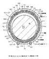
図1を参照して本発明による傾斜計の例を説明する。本例の傾斜計は、球形質量部10とそれを囲む球殻部100とを有する。球形質量部10の外径は球殻部100の球面状内面の内径より僅かに小さい。球形質量部10の周囲には間隙11が形成される。この間隙11は、開放空間であってよいが、好ましくは密閉空間である。また、この間隙は真空であってよいが、適当な不活性ガス又は液体によって充填されてよい。
【0010】
球形質量部10は球殻部100内にて自由に動くことができる。傾斜計が静止しているとき、球形質量部10(中心をO1とする。)は球殻部100(中心をOとする。)の球面状内面の最下端にて静止する。球形質量部10の直径は数ミリメートル以下であり、例えば、1mmであってよい。間隙11の厚さは、球形質量部10の最上端にて最大となるが、平均は、数μmであってよい。
【0011】
球殻部100は、最も内側の電極101〜106及び107(図1では電極101、102、105、106、107のみ図示)とその外側の絶縁体膜130とその外側の電路パターン111〜117及び121〜127とその外側の構造膜132とを有する。電極101〜106及び107は、絶縁体膜130の一部である細い絶縁部131によって互いに分離されており、各電極には対応する電路パターン111〜117及び121〜127が電気的に接続されている。
【0012】
尚、球殻部100の下端にはバンプ129が形成されている。バンプ129は構造膜132に形成された孔に装着され、電路パターン111〜117及び121〜127に接続されている。
【0013】
電極101〜106、107及び電路パターン111〜117及び121〜127は導電体、例えば、金属膜によって形成され、絶縁体膜130及び絶縁部131は絶縁体、例えば、二酸化ケイ素SiO2によって形成される。構造膜132は絶縁体、例えば、熱硬化性樹脂より形成される。
【0014】
本例では、構造膜132の厚さは、電極、電路パターン及び絶縁体膜に比べて、大きい。従って、構造膜132は、内側の構成部を保護する保護膜として機能すると同時に球殻部100に構造的強度を提供する。
【0015】
図2を参照して説明する。図2は球形質量部10と電極101〜107のみを示し、球殻部100の他の構成部、即ち、絶縁体膜130、電路パターン111〜117及び121〜127及び構造膜132は省略して描かれている。
【0016】
図示のように、球殻部100の中心に原点Oをとり、原点Oを通る直交3軸を設定する。傾斜計が水平面上に配置されているときに、水平面上にX1−X2軸及びY1−Y2軸をとり、垂直にZ1−Z2軸をとる。
【0017】
本例によると、電極は、X1−X2軸に沿って配置された第1及び第2の傾斜検出電極101及び102とY1−Y2軸に沿って配置された第3及び第4の傾斜検出電極103及び104とZ1−Z2軸に沿って配置された第5及び第6の傾斜検出電極105及び106と、これらの傾斜検出電極の間に配置されたシールド電極107とを含む。
【0018】
この例では、6個の傾斜検出電極101〜106は円形であり、シールド電極107は6個の傾斜検出電極101〜106の残りの部分を占めるように形成されている。
【0019】
図3を参照して説明する。図3は図1に示す傾斜計より構造膜132を除去した球殻部100の外観を示す図である。図3Aは、本例の傾斜計をY1軸方向に沿って見た図であり、図2BはZ2軸方向に沿って見た図である。絶縁体膜130の外面には上述のように電路パターン111〜117及び121〜127が形成されている。電路パターンは図示のように、電極101〜106、107に接続された端子パターン111〜116、117とこれらの端子パターン111〜116、117より延在する配線パターン121〜126、127とを有する。
【0020】
図3Bに示すように、これらの配線パターン121〜126、127の先端部は、球殻部100の下側に集中化されている。配線パターン121〜126、127の先端部は、例えば、図示のように、同一円に沿って配置されている。配線パターン121〜126、127の先端部は、図1に示したようにバンプに接続される。
【0021】
図4及び図5を参照して本例の傾斜計の動作を説明する。図示のように、空間に直交3軸、即ち、xyz軸を設定する。図5に示すように、空間上の点Pは球極座標(r,θ,ψ)によって表される。
【0022】
【数1】
x=rsinθcosψ
y=rsinθsinψ
z=rcosθ
【0023】
上述のように、球殻部100に、直交3軸、即ち、X1−X2軸、Y1−Y2軸及Z1−Z2軸が設定されている。このうちの1軸、例えば、Z1−Z2軸を傾斜計の基準軸とする。垂直軸、即ち、z軸に対する基準軸Z1−Z2の傾斜角θが、傾斜計及び被測定対象の傾斜角である。
【0024】
本例によると、基準軸Z1−Z2の傾斜角θの他に、基準軸Z1−Z2の傾斜方向又は方位角ψが求められる。
【0025】
球形質量部10は、球殻部100の内部にて自由に動くことができるが、傾斜計が静止すると、球殻部100の内面の最下点にて静止する。図示のように、基準軸Z1−Z2が球殻部100の内面と交差する点をA、Bとする。基準軸Z1−Z2の傾斜角θがゼロのとき、球形質量部10は下側の交差点Aにて球殻部100と接し、上側の交差点Bにて球殻部100と最大の間隙を形成する。
【0026】
基準軸Z1−Z2が垂直軸、即ち、z軸に対して傾斜すると、球形質量部10が球殻部100と接する点ZDは下側の交差点Aより偏奇する。球形質量部10と球殻部100の接点ZDと下側の交差点Aの間の偏奇量は傾斜角θに比例する。同様に、基準軸Z1−Z2が垂直軸、即ち、z軸に対して傾斜すると、球形質量部10と球殻部100の間の間隙が最大となる点ZUは上側の交差点Bより偏奇する。間隙が最大となる点ZUと上側の交差点Bの間の偏奇量は傾斜角θに比例する。
【0027】
従って、球殻部100の内面上の球形質量部10が球殻部100と接する点、即ち、球形質量部10と球殻部100の間の間隙がゼロとなる点ZDが求められれば傾斜角θが得られる。同様に、球殻部100の内面上の球形質量部10と球殻部100の間の間隙が最大となる点ZUが求められれば傾斜角θが得られる。間隙がゼロとなる点ZD又は間隙が最大となる点ZUは、傾斜検出電極からの出力信号によって求められる。
【0028】
図6を参照して説明する。図6は球形質量部10と6個の傾斜検出電極101〜106をコンデンサ501〜506によって置き換えた等価回路を示す。球形質量部10と電極は導電性材料より構成され、両者はコンデンサを形成する。尚、電極101〜106及び球形質量部10の表面は適当な非導電体膜によって被膜されてよい。各コンデンサの静電容量は、コンデンサの間隔によって変化する。即ち、各コンデンサの静電容量は、そのコンデンサを構成する球形質量部10と傾斜検出電極の間の距離によって変化する。
【0029】
各コンデンサ501〜506の静電容量の変化は各コンデンサに印加する電圧Vx1、Vx2、Vy1、Vy2、Vz1、Vz2の変化量を検出することによって検出することができる。
【0030】
コンデンサ501〜506の静電容量を測定することによって、球殻部100の内面上の間隙がゼロとなる点ZD又は間隙が最大となる点ZUが得られる。こうして、間隙がゼロとなる点ZD又は間隙が最大となる点ZUが得られると、それより、基準軸Z1−Z2の傾斜角及び傾斜方向が求められる。
【0031】
図7を参照して傾斜検出電極の形状の他の例を説明する。傾斜検出電極は、好ましくは、球殻部100の球面状内面に点対称に形成される。傾斜検出電極の点対称的な配置は、例えば、正多面体を利用して形成される。球殻部100の内面100Aに内接する正多面体を想定する。球殻部100の中心Oに点光源を配置し、その光によって正多面体の各面の投影像を球殻部100の内面100Aに投射する。こうして球殻部100の球面状内面上に正多面体の各面に対応した電極形状が描かれる。図7には正12面体及び正20面体が描かれているが、他の正多面体も可能である。
【0032】
図8を参照して傾斜電極の形状の更に他の例を示す。本例では、傾斜電極はメシュ状に形成されている。球殻部100の内面に、図示のように多数の経度方向の分離線及び緯度方向の分離線によって互いに分割された多数の傾斜検出電極が形成されている。こうして多数のメッシュ状の電極を用いることによって、間隙がゼロとなる点ZD又は間隙が最大となる点ZUが容易に得られる。
【0033】
先ずメッシュ状電極の各々に番号を付与し、各電極の緯度及び経度を予め求める。メッシュ状電極の面積は十分小さく、各電極の緯度及び経度はその中心位置の緯度及び経度によって表される。即ち、球形質量部10の接触点は、球形質量部10が接触している電極の中心位置であると近似してよい。球形質量部10が接触している電極の番号を検出することによって、その電極の緯度及び経度が求められる。こうして検出された電極の緯度及び経度は基準軸Z1−Z2の傾斜角及び傾斜方向を示す。
【0034】
図9及び図10を参照して本発明による傾斜計の他の例を説明する。図10は図9の傾斜計の球形質量部10と電極の等価回路を示す。電極の形状は特に図示されていないが、上述のいずれの電極の例が使用されてもよい。本例によると、互いに隣接する2つの電極によってスイッチ161〜164が構成される。隣接する電極の一方に直流電源160を接続し、隣接する電極の他方に電圧検出用の出力端子151、152、153、154を接続する。
【0035】
球形質量部10及び電極又はそれらの表面を導電体によって形成する。図9Bに示すように、球形質量部10が最下端にある隣接する2つの電極に接触すると、その2つの電極は電気的に接続される。即ち、最下端にある隣接する2つの電極によって構成されるスイッチはオンとなる。
【0036】
球形質量部10が接触する電極は最下端の電極だけである。即ち、球形質量部10によってオンとなるスイッチは1つだけであり、他のスイッチはオフとなっている。従って、オンとなっているスイッチを検出することによって最下端にある電極が知られる。最下端の電極が判れば、上述のように基準軸の傾斜角及び傾斜方向が検出される。
【0037】
尚、球形質量部10が最下端の2つの電極に接触している場合には、それに対応したスイッチがオンとなるが、球形質量部10が最下端の1つの電極にのみ接触している場合には、オンとなるスイッチはない。しかしながら、この場合、傾斜計を僅かに動かし、球形質量部10を、いずれかの互いに隣接する2つの電極に接触させることによって、そのスイッチがオンとなる。
【0038】
以上本発明の実施例について詳細に説明したが、本発明は上述の実施例に限ることなく本発明の要旨を逸脱することなく他の種々の構成が採りうることは当業者にとって容易に理解されよう。
【0039】
【発明の効果】
本発明によれば、球形質量部とその周囲に且つそれに近接して配置された電極からなる極めて小型の傾斜計を提供することができる利点がある。
【図面の簡単な説明】
【図1】本発明の傾斜計の構造の例を示す図である。
【図2】本発明の傾斜計の電極の例を示すための説明図である。
【図3】本発明の傾斜計の電極及び配線パターンを示す説明図である。
【図4】本発明の傾斜計の動作を説明するための説明図である。
【図5】球極座標を説明する説明図である。
【図6】本発明の傾斜計の等価回路を示す図である。
【図7】本発明の傾斜計の電極の他の例を示す図である。
【図8】本発明の傾斜計の電極の更に他の例を示す図である。
【図9】本発明の傾斜計の更に他の例を示す図である。
【図10】図9の傾斜計の電極の等価回路を示す図である。
【符号の説明】
10…球形質量部、 11…間隙、 100…球殻部、 101,102,103,104,105,106…電極パターン、 107…シールド電極、 111,112,113,114,115,116,117…端子パターン、 121,122,123,124,125,126,127…配線パターン、 129…バンプ、 130…絶縁体膜、 132…構造膜[0001]
[Industrial application fields]
The present invention relates to an inclinometer or clinometer for detecting an inclination angle with respect to a horizontal plane or a vertical axis. The present invention particularly relates to an extremely small inclinometer or clinometer suitable for use in robotics, virtual reality products and the like.
[0002]
[Prior art]
In recent years, various products have been developed in the field of mechatronics such as robotics and virtual reality. These products use extremely small sensors. Examples of such sensors include a gyro, an accelerometer, and an inclinometer.
[0003]
Conventionally, inclinometers using various principles are used. Typically, inclinometers configured to measure the tilt angle by filling a container with a liquid and measuring the tilt of the liquid level are well known and used.
[0004]
[Problems to be solved by the invention]
However, it has been difficult to miniaturize conventional inclinometers to such an extent that they can be adapted to various uses of mechatronic products. In particular, it is difficult to reduce the size of an inclinometer that uses the inclination of the liquid level.
[0005]
In view of such a point, the present invention has an object to provide an inclinometer having a very small size.
[0006]
[Means for Solving the Problems]
The inclinometer of the present invention is configured such that the spherical mass portion is movably disposed in a space inside the spherical inner surface and a spherical inner surface having a reference axis, andthe spherical inner surface of the spherical shell portion. A plurality of planar detection electrodesdisposed along the spherical inner surface of the spherical shell at positions corresponding to each surface of a regular polyhedron having six or more inscribed surfaces; and the plurality of detections A shield electrode that is insulated from the electrode and disposed on the spherical inner surface of the spherical shell, and detecting a capacitance between each of the plurality of detection electrodes and the shield electrode, The tilt angle of the reference axis is calculated.
[0007]
Therefore, the inclinometer of the present invention can be configured as a very small device.
[0009]
DETAILED DESCRIPTION OF THE INVENTION
An example of an inclinometer according to the present invention will be described with reference to FIG. The inclinometer of this example has a
[0010]
The
[0011]
The
[0012]
A
[0013]
The
[0014]
In this example, the thickness of the
[0015]
This will be described with reference to FIG. FIG. 2 shows only the
[0016]
As shown in the drawing, the origin O is set at the center of the
[0017]
According to this example, the electrodes include first and second
[0018]
In this example, the six
[0019]
This will be described with reference to FIG. FIG. 3 is a view showing the external appearance of the
[0020]
As shown in FIG. 3B, the end portions of these
[0021]
The operation of the inclinometer of this example will be described with reference to FIGS. As shown in the figure, three orthogonal axes, that is, xyz axes are set in the space. As shown in FIG. 5, the point P in space is represented by spherical pole coordinates (r, θ, ψ).
[0022]
[Expression 1]
x = rsin θ cos ψ
y = rsinθsinψ
z = r cos θ
[0023]
As described above, the
[0024]
According to this embodiment, in addition to the inclination angle of the reference axis Z1 -Z2 theta, the inclination direction or azimuth of the reference axis Z1 -Z2 ψ is determined.
[0025]
The
[0026]
When the reference axis Z1 -Z2 is inclined with respect to the vertical axis, that is, the z axis, the point ZD at which the
[0027]
Therefore, if the point where the
[0028]
This will be described with reference to FIG. FIG. 6 shows an equivalent circuit in which the
[0029]
Changes in the capacitances of the
[0030]
By measuring the capacitances of the
[0031]
Another example of the shape of the tilt detection electrode will be described with reference to FIG. The tilt detection electrode is preferably formed point-symmetrically on the spherical inner surface of the
[0032]
Still another example of the shape of the gradient electrode will be described with reference to FIG. In this example, the inclined electrode is formed in a mesh shape. On the inner surface of the
[0033]
First, a number is assigned to each mesh electrode, and the latitude and longitude of each electrode are obtained in advance. The area of the mesh electrode is sufficiently small, and the latitude and longitude of each electrode are represented by the latitude and longitude of the center position. That is, the contact point of the
[0034]
Another example of the inclinometer according to the present invention will be described with reference to FIGS. FIG. 10 shows an equivalent circuit of the
[0035]
The
[0036]
The only electrode with which the
[0037]
When the
[0038]
Although the embodiments of the present invention have been described in detail above, it is easily understood by those skilled in the art that the present invention is not limited to the above-described embodiments and can adopt other various configurations without departing from the gist of the present invention. Like.
[0039]
【The invention's effect】
According to the present invention, there is an advantage that it is possible to provide an extremely small inclinometer comprising a spherical mass portion and electrodes arranged around and in the vicinity thereof.
[Brief description of the drawings]
FIG. 1 is a diagram showing an example of the structure of an inclinometer of the present invention.
FIG. 2 is an explanatory diagram for illustrating an example of an electrode of the inclinometer of the present invention.
FIG. 3 is an explanatory diagram showing electrodes and wiring patterns of the inclinometer of the present invention.
FIG. 4 is an explanatory diagram for explaining the operation of the inclinometer of the present invention.
FIG. 5 is an explanatory diagram explaining spherical pole coordinates.
FIG. 6 is a diagram showing an equivalent circuit of the inclinometer of the present invention.
FIG. 7 is a view showing another example of electrodes of the inclinometer of the present invention.
FIG. 8 is a view showing still another example of the electrode of the inclinometer of the present invention.
FIG. 9 is a view showing still another example of the inclinometer of the present invention.
10 is a diagram showing an equivalent circuit of electrodes of the inclinometer of FIG. 9. FIG.
[Explanation of symbols]
DESCRIPTION OF
Claims (3)
Translated fromJapanese球面状の内面の内側の空間に前記球形質量部を可動に配置し、基準軸線を有する球殻部と、
前記球殻部の球面状の内面に内接する6面以上の面を有する正多面体の各面に対応した位置であって、前記球殻部の球面状の内面に沿って配置された面状の複数の検出電極と、
前記複数の検出電極と絶縁されて、前記球殻部の球面状の内面に配置されたシールド電極と、
を有し、
前記複数の検出電極のそれぞれと前記シールド電極の間で静電容量を検出することにより、前記基準軸線の傾斜角を演算するように構成されている傾斜計。A spherical mass,
A spherical shell having a reference axis, wherein the spherical mass is movably disposed in a space inside the spherical inner surface;
A planar shape disposed along the spherical inner surface of the spherical shell at a position corresponding to each surface of a regular polyhedron having six or more surfaces inscribed in the spherical inner surface of the spherical shell. A plurality of detection electrodes;
A shield electrode insulated from the plurality of detection electrodes and disposed on a spherical inner surface of the spherical shell,
Have
An inclinometer configured to calculate an inclination angle of the reference axis by detecting capacitance between each of the plurality of detection electrodes and the shield electrode.
Priority Applications (2)
| Application Number | Priority Date | Filing Date | Title |
|---|---|---|---|
| JP15187299AJP4270647B2 (en) | 1999-05-31 | 1999-05-31 | Inclinometer |
| US09/449,882US6505409B2 (en) | 1999-05-31 | 1999-11-30 | Inclinometer |
Applications Claiming Priority (1)
| Application Number | Priority Date | Filing Date | Title |
|---|---|---|---|
| JP15187299AJP4270647B2 (en) | 1999-05-31 | 1999-05-31 | Inclinometer |
Publications (2)
| Publication Number | Publication Date |
|---|---|
| JP2000337872A JP2000337872A (en) | 2000-12-08 |
| JP4270647B2true JP4270647B2 (en) | 2009-06-03 |
Family
ID=15528068
Family Applications (1)
| Application Number | Title | Priority Date | Filing Date |
|---|---|---|---|
| JP15187299AExpired - Fee RelatedJP4270647B2 (en) | 1999-05-31 | 1999-05-31 | Inclinometer |
Country Status (2)
| Country | Link |
|---|---|
| US (1) | US6505409B2 (en) |
| JP (1) | JP4270647B2 (en) |
Families Citing this family (21)
| Publication number | Priority date | Publication date | Assignee | Title |
|---|---|---|---|---|
| US6695885B2 (en) | 1997-02-26 | 2004-02-24 | Alfred E. Mann Foundation For Scientific Research | Method and apparatus for coupling an implantable stimulator/sensor to a prosthetic device |
| WO2000065360A1 (en)* | 1999-04-27 | 2000-11-02 | Tokimec Inc. | Accelerometer and spherical sensor type measuring instrument |
| IL140206A (en)* | 2000-12-10 | 2006-08-20 | Federico Singer | Inclination measurement apparatus |
| JPWO2002050616A1 (en)* | 2000-12-20 | 2004-04-22 | セイコーインスツルメンツ株式会社 | Mechanical timepiece with posture detecting device and posture detecting device |
| JP2002286959A (en) | 2000-12-28 | 2002-10-03 | Canon Inc | Semiconductor device, photoelectric fusion substrate, and method of manufacturing the same |
| JP4805479B2 (en)* | 2001-06-05 | 2011-11-02 | 日帝無線株式会社 | Normally closed tilt vibration sensor |
| WO2003048677A2 (en) | 2001-07-30 | 2003-06-12 | Yuval Singer | Inclination measurement apparatus |
| JP3927883B2 (en) | 2002-08-02 | 2007-06-13 | キヤノン株式会社 | Optical waveguide device and photoelectric fusion substrate using the same |
| US20050217127A1 (en)* | 2004-04-05 | 2005-10-06 | Prueftechnik Dieter Busch Ag | Measurement device and method for determining the three-dimensional orientation of a body relative to two horizontal reference directions |
| US7794499B2 (en)* | 2004-06-08 | 2010-09-14 | Theken Disc, L.L.C. | Prosthetic intervertebral spinal disc with integral microprocessor |
| FR2878324A1 (en)* | 2004-11-24 | 2006-05-26 | Hispano Suiza Sa | Movable object`s e.g. aircraft, rotational angle measurement device, has displacement measurement sensors permitting to measure distances between spherical cavity and ball irrespective of relative movement of case with respect to ball |
| JP4291858B2 (en)* | 2007-03-27 | 2009-07-08 | Okiセミコンダクタ株式会社 | Tilt position sensor and method of manufacturing tilt position sensor |
| KR100907826B1 (en) | 2007-08-29 | 2009-07-14 | 한국전자통신연구원 | 3-D tilt angle calculation circuit |
| JP2007333749A (en)* | 2007-09-07 | 2007-12-27 | Japan Aviation Electronics Industry Ltd | Capacitance accelerometer |
| US7886451B2 (en)* | 2008-03-05 | 2011-02-15 | The Fredericks Company | Integral electrode tilt sensor and method for making same |
| EP2572336B1 (en)* | 2010-05-18 | 2021-09-15 | Teknologian Tutkimuskeskus VTT | Mobile device, server arrangement and method for augmented reality applications |
| US8806769B2 (en) | 2011-11-02 | 2014-08-19 | Hoon Kiang Tan | Bullseye indicator and method |
| CN103808303A (en)* | 2014-03-06 | 2014-05-21 | 湖南科技学院 | Spherical surface capacitive type plane level detection sensor |
| WO2016141360A1 (en)* | 2015-03-04 | 2016-09-09 | California Institute Of Technology | Position sensing and guiding system |
| US9581444B2 (en) | 2015-06-29 | 2017-02-28 | International Business Machines Corporation | Electronic roll pitch and yaw sensor using conductive fluid |
| US11170625B2 (en) | 2018-05-18 | 2021-11-09 | California Institute Of Technology | Head positioner for retinal surgery patients |
Family Cites Families (16)
| Publication number | Priority date | Publication date | Assignee | Title |
|---|---|---|---|---|
| US3611345A (en)* | 1969-04-16 | 1971-10-05 | Intron Int Inc | Motion detector |
| US3701093A (en)* | 1971-07-29 | 1972-10-24 | Steve J Pick | Tilt indication apparatus |
| USRE31473E (en) | 1977-02-07 | 1983-12-27 | Texas Instruments Incorporated | System for fabrication of semiconductor bodies |
| US4493155A (en)* | 1982-09-29 | 1985-01-15 | Combustion Engineering, Inc. | Apparatus for remotely indicating angular position |
| JPS6061612A (en)* | 1983-09-14 | 1985-04-09 | Olympus Optical Co Ltd | Posture detecting sensor |
| US5010893A (en)* | 1987-01-15 | 1991-04-30 | Siemens-Pacesetter, Inc. | Motion sensor for implanted medical device |
| JPH02119241A (en) | 1988-10-28 | 1990-05-07 | Matsushita Electric Ind Co Ltd | Semiconductor integrated circuit device |
| US5168138A (en)* | 1991-05-29 | 1992-12-01 | Texas Instruments Incorporated | Multi-ball position switch |
| US5450676A (en)* | 1993-06-18 | 1995-09-19 | Thornsberry; William H. | Slope angle and level indicator apparatus |
| US5462639A (en) | 1994-01-12 | 1995-10-31 | Texas Instruments Incorporated | Method of treating particles |
| DE4412294A1 (en)* | 1994-04-09 | 1995-10-12 | Braun Ag | Safety shutdown |
| US5726480A (en) | 1995-01-27 | 1998-03-10 | The Regents Of The University Of California | Etchants for use in micromachining of CMOS Microaccelerometers and microelectromechanical devices and method of making the same |
| US5808254A (en)* | 1996-07-12 | 1998-09-15 | Wu; Tey-Jen | Switch for four-quarters clock |
| US5774055A (en)* | 1997-06-09 | 1998-06-30 | Pomerantz; David | Infant monitoring device |
| US6148669A (en)* | 1998-06-29 | 2000-11-21 | U.S. Philips Corporation | Acceleration sensor with a spherical inductance influencing member |
| US6198396B1 (en)* | 1998-09-11 | 2001-03-06 | Mine Safety Appliances Company | Motion sensor |
- 1999
- 1999-05-31JPJP15187299Apatent/JP4270647B2/ennot_activeExpired - Fee Related
- 1999-11-30USUS09/449,882patent/US6505409B2/ennot_activeExpired - Fee Related
Also Published As
| Publication number | Publication date |
|---|---|
| US20020073563A1 (en) | 2002-06-20 |
| US6505409B2 (en) | 2003-01-14 |
| JP2000337872A (en) | 2000-12-08 |
Similar Documents
| Publication | Publication Date | Title |
|---|---|---|
| JP4270647B2 (en) | Inclinometer | |
| US4866850A (en) | Clinometer with rolling liquid conductor | |
| JP3327595B2 (en) | 3-axis accelerometer | |
| US4747216A (en) | Clinometer/accelerometer and method | |
| CN101893451B (en) | Capacitor type sensor and gyroscope | |
| CN107328402A (en) | A kind of three axis MEMS gyro | |
| WO2010021395A1 (en) | Acceleration switch | |
| CN107677261B (en) | Micro- hemisphere gyroscope of interior outer hyperboloid stereo electrod | |
| JP3644799B2 (en) | Tilt sensor | |
| US5774373A (en) | Apparatus and method for measuring an object's angular inclination in multiple axes | |
| JP3764400B2 (en) | Capacitive tilt sensor | |
| KR100332813B1 (en) | Movable coordinate inputting apparatus | |
| JP3646221B2 (en) | Electric signal generator that responds to changes in position and orientation | |
| JP3726191B2 (en) | Electric signal generator that responds to changes in position and orientation | |
| KR20120107705A (en) | The digital angle measurement sensor or device by the electronic circuit sensing pad in the liquid material which has horizontal plane | |
| JP3856802B2 (en) | Electric signal generator that responds to changes in position and orientation | |
| RU2071032C1 (en) | Device for detection of mechanical actions | |
| US20250178885A1 (en) | Microelectromechanical motion sensor device having a single proof mass | |
| JP3771784B2 (en) | Tilt sensor | |
| US20250306057A1 (en) | Physical Quantity Sensor And Inertial Measurement Unit | |
| KR102165303B1 (en) | Inclination angle measurement system using mechanical switch | |
| CN106885921A (en) | Direction sensor | |
| JPH0327071B2 (en) | ||
| JPH0678884B2 (en) | Capacitive displacement sensor | |
| SU440552A1 (en) | Vertical Electrolytic Sensor |
Legal Events
| Date | Code | Title | Description |
|---|---|---|---|
| RD03 | Notification of appointment of power of attorney | Free format text:JAPANESE INTERMEDIATE CODE: A7423 Effective date:20040205 | |
| A521 | Written amendment | Free format text:JAPANESE INTERMEDIATE CODE: A821 Effective date:20040205 | |
| A621 | Written request for application examination | Free format text:JAPANESE INTERMEDIATE CODE: A621 Effective date:20060509 | |
| A977 | Report on retrieval | Free format text:JAPANESE INTERMEDIATE CODE: A971007 Effective date:20080409 | |
| A131 | Notification of reasons for refusal | Free format text:JAPANESE INTERMEDIATE CODE: A131 Effective date:20080603 | |
| A521 | Written amendment | Free format text:JAPANESE INTERMEDIATE CODE: A523 Effective date:20080801 | |
| A131 | Notification of reasons for refusal | Free format text:JAPANESE INTERMEDIATE CODE: A131 Effective date:20081007 | |
| A521 | Written amendment | Free format text:JAPANESE INTERMEDIATE CODE: A523 Effective date:20081208 | |
| TRDD | Decision of grant or rejection written | ||
| A01 | Written decision to grant a patent or to grant a registration (utility model) | Free format text:JAPANESE INTERMEDIATE CODE: A01 Effective date:20090217 | |
| A01 | Written decision to grant a patent or to grant a registration (utility model) | Free format text:JAPANESE INTERMEDIATE CODE: A01 | |
| A61 | First payment of annual fees (during grant procedure) | Free format text:JAPANESE INTERMEDIATE CODE: A61 Effective date:20090224 | |
| FPAY | Renewal fee payment (event date is renewal date of database) | Free format text:PAYMENT UNTIL: 20120306 Year of fee payment:3 | |
| R150 | Certificate of patent or registration of utility model | Free format text:JAPANESE INTERMEDIATE CODE: R150 | |
| LAPS | Cancellation because of no payment of annual fees |