JP4267036B2 - Display control apparatus and display control method - Google Patents
Display control apparatus and display control methodDownload PDFInfo
- Publication number
- JP4267036B2 JP4267036B2JP2007002055AJP2007002055AJP4267036B2JP 4267036 B2JP4267036 B2JP 4267036B2JP 2007002055 AJP2007002055 AJP 2007002055AJP 2007002055 AJP2007002055 AJP 2007002055AJP 4267036 B2JP4267036 B2JP 4267036B2
- Authority
- JP
- Japan
- Prior art keywords
- display
- pixels
- image
- content
- unit
- Prior art date
- Legal status (The legal status is an assumption and is not a legal conclusion. Google has not performed a legal analysis and makes no representation as to the accuracy of the status listed.)
- Expired - Fee Related
Links
Images


Classifications
- G—PHYSICS
- G06—COMPUTING OR CALCULATING; COUNTING
- G06T—IMAGE DATA PROCESSING OR GENERATION, IN GENERAL
- G06T3/00—Geometric image transformations in the plane of the image
- G06T3/40—Scaling of whole images or parts thereof, e.g. expanding or contracting
- G06T3/4084—Scaling of whole images or parts thereof, e.g. expanding or contracting in the transform domain, e.g. fast Fourier transform [FFT] domain scaling
Landscapes
- Physics & Mathematics (AREA)
- General Physics & Mathematics (AREA)
- Engineering & Computer Science (AREA)
- Theoretical Computer Science (AREA)
- Controls And Circuits For Display Device (AREA)
- Control Of Indicators Other Than Cathode Ray Tubes (AREA)
- Transforming Electric Information Into Light Information (AREA)
- Television Systems (AREA)
- Two-Way Televisions, Distribution Of Moving Picture Or The Like (AREA)
Description
Translated fromJapanese本発明は、表示制御装置及び表示制御方法に関し、特にコンテンツの画像を拡大した拡大画像を表示可能な表示制御装置及び表示制御方法に関する。 The present invention relates to a display control apparatus and a display control method, and more particularly, to a display control apparatus and a display control method capable of displaying an enlarged image obtained by enlarging a content image.
現行のデジタルテレビ放送では、SD(Standard Definision:標準解像度)のコンテンツやHD(High Definision:高解像度)のコンテンツが混在している。SDコンテンツは例えば720×480画素のコンテンツであり、HDコンテンツは例えば1280×720或いは1920(1440)×1080画素のコンテンツである。また、DVD(Digital Versatile Disc)等の蓄積メディア、インターネット放送、VOD(Video On Demand)等においても、SDのコンテンツ(SDコンテンツ)とHDのコンテンツ(HDコンテンツ)が混在している。 In the current digital television broadcasting, SD (Standard Definition) content and HD (High Definition) content are mixed. The SD content is, for example, content of 720 × 480 pixels, and the HD content is, for example, content of 1280 × 720 or 1920 (1440) × 1080 pixels. In addition, SD content (SD content) and HD content (HD content) are mixed in storage media such as DVD (Digital Versatile Disc), Internet broadcast, VOD (Video On Demand), and the like.
SDコンテンツに対応したディスプレイとしては、例えば720×480画素のディスプレイがある。また、HDコンテンツに対応したディスプレイとしては、例えば1280×720画素や1920×1080画素のディスプレイがある。近年は、徐々にHD対応ディスプレイが普及してきている。 As a display corresponding to the SD content, for example, there is a display of 720 × 480 pixels. In addition, as a display corresponding to the HD content, for example, there are displays of 1280 × 720 pixels and 1920 × 1080 pixels. In recent years, HD-compatible displays are gradually spreading.
ここで、HD対応ディスプレイにSDコンテンツの画像を表示する手法は大きく2つの手法に分けられる。第一の手法は、SDコンテンツをHD対応ディスプレイの画素数に合わせて画素変換し、HD対応ディスプレイの画面全体にSDコンテンツの画像を拡大して表示する手法である。第二の手法は、SDコンテンツを画素変換せずに、HD対応ディスプレイの画面の一部に表示する手法である。 Here, the method of displaying the SD content image on the HD compatible display is roughly divided into two methods. The first method is a method in which SD content is subjected to pixel conversion in accordance with the number of pixels of an HD compatible display, and an image of the SD content is enlarged and displayed on the entire screen of the HD compatible display. The second method is a method for displaying SD content on a part of the screen of an HD compatible display without pixel conversion.
下記の特許文献1には、SD画像をHD画像に変換する方法が開示されている。これによれば、SD画像に対応するHD画像を遺伝的操作により生成し、生成したHD画像をSD画像に変換して、元のSD画像と比較して変換結果の妥当性を評価する。
近年、HDよりもさらに高解像度のスーパーハイビジョンと呼ばれるコンテンツ及びディスプレイの研究・開発が日本放送協会(NHK)の放送技術研究所を中心に行われている。スーパーハイビジョンコンテンツ(以下、SHVコンテンツと称する)の映像フォーマットは、7680×4320(8k×4k)画素となっている。また、一方では、4k×2k画素の映像フォーマットを有するデジタル・シネマの開発も進められている。スーパーハイビジョン(SHV)対応のディスプレイとしては、7680×4320(8k×4k)画素のディスプレイや、4096×2160(4k×2k)画素のディスプレイ等が想定されている。 In recent years, research and development of contents and displays called Super Hi-Vision with higher resolution than HD has been conducted mainly by the Broadcasting Technology Laboratory of the Japan Broadcasting Corporation (NHK). The video format of the super high-vision content (hereinafter referred to as SHV content) is 7680 × 4320 (8k × 4k) pixels. On the other hand, development of a digital cinema having a video format of 4k × 2k pixels is also in progress. As a display for Super Hi-Vision (SHV), a display of 7680 × 4320 (8k × 4k) pixels, a display of 4096 × 2160 (4k × 2k) pixels, and the like are assumed.
ここで、1920×1080画素のHDコンテンツの画素数は、720×480画素のSDコンテンツの画素数の約6倍である。これに対して、7680×4320(8k×4k)画素のSHVコンテンツの画素数は、720×480画素のSDコンテンツの画素数の約96倍である。このため、8k×4k画素のSHV対応ディスプレイの画面全体にSDコンテンツの画像を拡大して表示すると、画素変換による大きな画質劣化が生じるので、ユーザに大きな違和感を与えることが想定される。一方、8k×4k画素のSHV対応ディスプレイの画面にSDコンテンツの画像を画素変換せずに表示する場合も、SHV対応ディスプレイの画面の1/96の領域にしか表示されないため、ユーザに大きな違和感を与えることが想定される。また、4k×2k画素のディスプレイにSDコンテンツの拡大画像を表示する場合も、同様にユーザに大きな違和感を与えることが想定される。 Here, the number of pixels of HD content of 1920 × 1080 pixels is about six times the number of pixels of SD content of 720 × 480 pixels. In contrast, the number of pixels of 7680 × 4320 (8k × 4k) SHV content is about 96 times the number of SD content of 720 × 480 pixels. For this reason, if the image of the SD content is enlarged and displayed on the entire screen of the 8k × 4k pixel SHV-compatible display, the image quality is greatly deteriorated due to the pixel conversion. On the other hand, even when an SD content image is displayed on the screen of an 8k × 4k pixel SHV-compatible display without pixel conversion, it is displayed only in 1/96 of the area of the SHV-compatible display screen. It is assumed to give. Similarly, when a magnified image of SD content is displayed on a 4k × 2k pixel display, it is assumed that the user is similarly discomforted.
このような課題を解決するためには、コンテンツに最適な表示画素数(例えば、画像特性の劣化が許容できる範囲内での最大の表示画素数)で表示することが望ましい。しかしながら、従来は、単純にディスプレイの画素数に合わせて画素変換を行ったり、ユーザが表示画素数を設定したりするのが一般的であり、コンテンツに最適な表示画素数を求める方法は提案されていない。 In order to solve such a problem, it is desirable to display with the optimal number of display pixels for the content (for example, the maximum number of display pixels within a range in which the deterioration of image characteristics can be allowed). However, conventionally, it is common to simply perform pixel conversion according to the number of pixels of the display, or the user sets the number of display pixels, and a method for obtaining the optimum number of display pixels for content has been proposed. Not.
特許文献1には、SD画像をHD画像に変換する方法が開示されているが、コンテンツに最適な表示画素数を求めて画素変換を行う方法は開示されていない。
そこで、本発明は、コンテンツの画像を最適な表示画素数で拡大表示させることができる表示制御装置及び表示制御方法を提供することを目的とする。 SUMMARY An advantage of some aspects of the invention is that it provides a display control apparatus and a display control method capable of enlarging and displaying a content image with an optimal number of display pixels.
上述した課題を解決するために、本発明に係る表示制御装置は、映像コンテンツの画素数よりも多い画素数を有する表示部に、映像コンテンツの画像を拡大した拡大画像を表示可能な表示制御装置であって、蓄積部に蓄積された映像コンテンツを構成する複数のフレームの画像から解析対象のフレームの画像を抽出して、映像コンテンツの画像を拡大した場合の画像特性を解析する解析手段と、解析手段による解析結果に基づいて、画像特性の劣化度合いが予め定められた劣化判定基準値を満たすように、映像コンテンツの画像を拡大した場合の表示画素数を決定する画素数決定手段と、再生指示に応答して、蓄積部に蓄積された映像コンテンツを再生する制御を行う制御手段と、再生指示を受けた映像コンテンツを構成する複数のフレームの画像の画素数を画素数決定手段で決定された表示画素数に変換して、該映像コンテンツの画像を拡大した拡大画像を表示部に出力する画素変換手段とを備え、解析手段は、解析対象のフレーム数を時間経過に応じて段階的に増加させて、画像特性を解析する処理を繰り返し実行し、画素数決定手段は、解析手段により繰り返し実行される解析処理の結果に基づいて、表示画素数を繰り返し決定しなおし、画素変換手段は、再生指示を受ける前に表示画素数決定手段により決定されている表示画素数になるように、映像コンテンツを構成する複数のフレームの画像の画素数を変換することを特徴とする。To solve the problems described above, the display control device according to the present invention, the display unit having a larger number of pixels than that of thevideo content, viewable display control unit an enlarged image obtained by enlarging the image of thevideo content An analyzing meansfor extracting an image of a frame to be analyzed from a plurality of frames constitutingthe video contentstored in thestorage unit and analyzing an image characteristicwhen the image of thevideo content is enlarged ;based on the analysis result by the analyzingmeans, so as to satisfy thedeterioration determination referencevalue degradation degree predeterminedimage characteristics, and pixel number determination means for determining the number of display pixels inthe case of enlarging the image of thevideo content,in response to the reproduction instruction, and a control means for controlling to reproduce the video content stored in the storage unit,a plurality of frames constituting thevideo contentwhich has received the reproduction instruction By converting the number of pixels of theimage to the number of display pixels which are determined by the pixel number determining means, and a pixel converting means for outputting to the display unit an enlarged imageobtained by enlarging the image of the videocontent,analyzing means analyzes the object The number of frames is gradually increased over time, and the process of analyzing the image characteristics is repeatedly executed, and the pixel number determination unit is configured to display pixels based on the result of the analysis process repeatedly executed by the analysis unit. The pixel conversion means determines the number of pixels of a plurality of frames constituting the video content so that the display pixel number is determined by the display pixel number determination means before receiving the reproduction instruction. conversion be characterized by Rukoto.
また、本発明の係わる表示制御方法は、映像コンテンツの画素数よりも多い画素数を有する表示部に、映像コンテンツの画像を拡大した拡大画像を表示可能とする表示制御方法であって、蓄積部に蓄積された映像コンテンツを構成する複数フレームの画像から解析対象のフレームの画像を抽出して、該映像コンテンツの画像を拡大した場合の画像特性を解析する解析ステップと、解析ステップによる解析結果に基づいて、画像特性の劣化度合いが予め定められた劣化判定基準値を満たすように、映像コンテンツの画像を拡大した場合の表示画素数を決定する画素数決定ステップと、再生指示に応答して、蓄積部に蓄積された映像コンテンツを再生する制御を行う再生ステップと、再生指示を受けた映像コンテンツを構成する複数のフレームの画像の画素数を画素数決定ステップで決定された表示画素数に変換して、該映像コンテンツの画像を拡大した拡大画像を表示部に出力する画素変換ステップとを備え、解析ステップは、解析対象のフレーム数を時間経過に応じて段階的に増加させて、画像特性を解析する処理を繰り返し実行し、画素数決定ステップは、解析ステップで繰り返し実行される解析処理の結果に基づいて、表示画素数を繰り返し決定しなおし、画素変換ステップは、再生指示を受ける前に表示画素数決定手段により決定されている表示画素数になるように、映像コンテンツを構成する複数のフレームの画像の画素数を変換することを特徴とする。
The display control method according the present invention, the display unit having a greater number of pixels thanvideo content, a display control method which enables displaying an enlarged image obtained by enlarging the image of the video content,the storage unit An analysis stepfor extracting an image of a frame to be analyzed from a plurality of frames constitutingthe video contentstored inthe image, and analyzing the image characteristicswhen the image ofthe video content is enlarged, and ananalysis result by the analysis stepInresponse to the reproduction instruction, a pixel number determining step for determining the number of display pixelswhen theimage of thevideo contentis enlarged so that thedegree of deterioration ofthe image characteristics satisfies a predetermineddeterioration determination referencevalue, a playback step of performing control to reproduce the video content stored in the storage unit,a plurality of frames constituting thevideo contentwhich has received the reproduction instruction By converting the number of pixels ofthe image to the number of display pixels which are determined by the pixel number determination step, and a pixel converting step of outputting to the display unit an enlarged imageobtained by enlarging the image of the videocontent,the analysis step is analyzed The number of frames is gradually increased over time, and the process of analyzing the image characteristics is repeatedly executed. The pixel number determination step is performed based on the result of the analysis process repeatedly executed in the analysis step. In the pixel conversion step, the number of pixels of the images of a plurality of frames constituting the video content is set so that the display pixel number is determined by the display pixel number determining means before receiving the reproduction instruction. conversion be characterized by Rukoto.
本発明によれば、コンテンツの画像特性を解析することにより、コンテンツの画像を最適な表示画素数で拡大表示させることが可能となる。 According to the present invention, an image of a content can be enlarged and displayed with an optimal number of display pixels by analyzing the image characteristics of the content.
(実施の形態1)
以下、本発明の実施の形態を図面を用いて説明する。図1は、本発明の実施の形態1に係る表示制御装置の概略構成を示すブロック図である。なお、本実施例において、デジタルテレビ放送のコンテンツを視聴することを想定している。また、伝送フォーマットはMPEG2(Moving Picture Expert Group2)のTS(Transport Stream)を想定している。(Embodiment 1)
Hereinafter, embodiments of the present invention will be described with reference to the drawings. FIG. 1 is a block diagram showing a schematic configuration of a display control apparatus according to
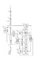
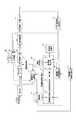
図1において、この表示制御装置は、受信部1、デマルチプレクサ2、映像復号部3、画素変換部4、映像出力部5、システム制御部6、蓄積処理部7、蓄積再生制御部8、コンテンツ蓄積部9を備える。さらに、表示制御装置は、画素数決定制御部10、最適画素数計算部11、映像復号部12、画素変換部13、解析部14、画素数決定部15、閾値記憶部16、画素数記憶部17及びリモコン18を備える。 In FIG. 1, this display control apparatus includes a
アンテナ(図示せず)で受信されたデジタル放送信号は、受信部1に入力される。(ケーブルテレビ回線やインターネット回線を経由したデジタル放送信号も含む)
受信部1は、入力されたデジタル放送信号からユーザの所望するチャンネルの信号を選局し、復調処理を施してMPEG2方式のTS信号をデマルチプレクサ2に出力する。デマルチプレクサ2は、多重化されたTS信号に対してデマルチプレクス処理を施し、映像信号(MPEG2−Video信号)、音声信号(MPEG2−Audio信号)等に分離して出力する。デマルチプレクサ2から出力された映像信号は、映像復号部3に与えられる。デマルチプレクサ2から出力された音声信号は音声復号部(図示せず)に与えられるが、ここでは、音声信号に関する処理は説明を省略する。A digital broadcast signal received by an antenna (not shown) is input to the receiving
The
映像復号部3は、デマルチプレクサ2からの映像信号を復号して出力する。画素変換部4は、映像復号部3から出力された映像信号に対して、システム制御部6により指示された表示画素数に変換する画素変換処理を行う。画素変換のアルゴリズムとしては、例えばバイキュービック法等の任意の手法を使用する。映像出力部5は、画素変換部4によって画素変換された映像信号を表示制御装置(図示せず)に出力する。 The
また、デマルチプレクサ2は、受信部1から出力されたTS信号から、蓄積するコンテンツの信号を抽出して蓄積処理部7に与える。蓄積処理部7は、蓄積するコンテンツのパケットを整形して、コンテンツ番号、蓄積日、コンテンツ長等の蓄積コンテンツ情報を付加する。 In addition, the
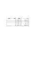
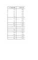
図2は、コンテンツ番号1〜4のコンテンツに付加される蓄積コンテンツ情報の一例を示す図である。図2において、蓄積コンテンツ情報として「蓄積コンテンツ番号」「蓄積日」「コンテンツ長」が付加されている。例えば、コンテンツ番号1に対応するコンテンツの蓄積日は2006/7/4であり、コンテンツ長は1時間32分10秒(1h32m10s)である。 FIG. 2 is a diagram illustrating an example of accumulated content information added to the contents of
図1に戻って、蓄積再生制御部8は、システム制御部6から蓄積要求を受けた場合に、蓄積処理部7から出力されたコンテンツをコンテンツ蓄積部9に蓄積する。また、蓄積再生制御部8は、システム制御部6から再生指示を受けた場合、コンテンツ蓄積部9に蓄積されたコンテンツを読み出してデマルチプレクサ2に与える。 Returning to FIG. 1, the storage
画素数決定制御部10は、コンテンツ蓄積部9からの蓄積コンテンツ情報に基づいて、最適画素数計算部11の動作の制御を行う。最適画素数計算部11は、コンテンツに最適な表示画素数を算出する。この最適画素数計算部11は、映像復号部12、画素変換部13、解析部14及び画素数決定部15を含む。なお、本発明において、最適な表示画素数とは、画像を拡大したときの画像特性の劣化が一定レベル以上悪くならない最大の表示画素数を意味する。コンテンツの画像を画素変換して拡大すると画像特性が劣化するため、本発明では画像特性が一定レベルよりも悪くならないように表示画素数を決定する。 The pixel number
映像復号部12は、コンテンツ蓄積部9に蓄積されたコンテンツの映像信号から任意のフレームを抜き出して復号する。画素変換部13は、映像復号部12によって復号された映像信号の画素変換を行う。解析部14は、画素変換部13による画素変換の結果を解析する。閾値記憶部16には、画像特性の劣化度合いを判定するための劣化判定閾値(判定基準値)が予め格納されている。画素数決定部15は、解析部14による解析結果と、閾値記憶部16から取得した劣化判定閾値とを比較して、コンテンツに最適な表示画素数を決定する。なお、画素数決定制御部10及び最適画素数計算部11によりコンテンツに最適な表示画素数を決定する処理については後述する。 The
画素数記憶部17は、画素数決定部15によって決定された表示画素数を保持する。また、この画素数記憶部17には、ディスプレイの画素数が予め格納される。システム制御部6は、画素数記憶部17に保持された画素数情報を取得して画素変換部4に設定する。また、このシステム制御部6は、リモコン18からのリモコン信号に応じて、蓄積再生制御部8の動作を制御する。 The pixel
なお、図1では、2つの映像復号部3,12及び2つの画素変換部4,13を設けた構成を示したが、1つの映像復号部3及び1つの画素変換部4を設けた構成にしてもよい。この場合は、映像復号部3及び画素変換部4を最適表示画素数の計算処理に兼用し、画素変換部4による画素変換の結果を解析部14で解析する構成にすればよい。 Although FIG. 1 shows a configuration in which two
ここで、本発明では、コンテンツに最適な表示画素数を決定する処理において、解析精度を段階的に高くしながら最適表示画素数を算出する。これにより、蓄積されたコンテンツの再生要求があった場合、その時点の解析精度で算出された最適表示画素数を用いて、コンテンツの画像を拡大して表示することが可能となる。 Here, in the present invention, in the process of determining the optimum display pixel number for the content, the optimum display pixel number is calculated while gradually increasing the analysis accuracy. As a result, when there is a request for reproduction of the accumulated content, it is possible to enlarge and display the content image using the optimum number of display pixels calculated with the analysis accuracy at that time.
図3は、解析精度を段階的に高くしながら最適表示画素数を決定する処理について説明するための図である。ここで、時刻t0にコンテンツの蓄積が開始され、時刻t4にコンテンツの蓄積が終了するものとする。 FIG. 3 is a diagram for explaining a process for determining the optimum number of display pixels while gradually increasing the analysis accuracy. Here, it is assumed that content accumulation starts at time t0 and content accumulation ends at time t4.
図1及び図3を参照して、時刻t0にコンテンツの蓄積が開始された後、最適画素数計算部11は、解析精度を段階的に高くしながらコンテンツに最適な表示画素数を計算する。具体的には、時刻t1に解析精度P(1)で演算処理が行われ、時刻t0〜t1の期間に蓄積されたコンテンツに対応する最適な表示画素数R(1)が算出される。続いて、時刻t3に解析精度P(1)よりも1段階高い精度の解析精度P(2)で演算処理が行われ、時刻t0〜t3の期間に蓄積されたコンテンツに対応する最適な表示画素数R(2)が算出される。続いて、時刻t6に解析精度P(2)よりも1段階高い精度の解析精度P(3)で演算処理が行われ、時刻t0〜t4の期間に蓄積されたコンテンツに対応する最適な表示画素数R(3)が算出される。 With reference to FIGS. 1 and 3, after the accumulation of content is started at time t0, the optimum pixel
時刻t2に、ユーザがリモコン18を操作して、蓄積されたコンテンツのタイムシフト再生を要求した場合(再生要求A)、システム制御部6は蓄積再生制御部8にコンテンツの再生を指示する。また、システム制御部6は、画素数記憶部17からその時点で算出されている最適表示画素数R(1)を取得し、画素変換部4に最適表示画素数R(1)を設定する。蓄積再生制御部8により再生されたコンテンツは、画素変換部4によって最適表示画素数R(1)に画素変換されてディスプレイに拡大表示される。また、時刻t5に、ユーザが蓄積されたコンテンツのタイムシフト再生を要求した場合は(再生要求B)、その時点で算出されている最適表示画素数R(2)に画素変換されてディスプレイに拡大表示される。このように、解析精度を段階的に高くしながら最適表示画素数を算出するため、蓄積されたコンテンツの再生要求がされた時点で算出されている最適表示画素数で、コンテンツの拡大画像をディスプレイに表示することが可能となる。 When the user operates the
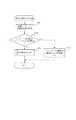
次に、コンテンツに最適な表示画素数を決定する処理について説明する。図4は、最適表示画素数を決定する処理を示す第1のフローチャートである。図1及び図4を用いて、画素数決定制御部10及び最適画素数計算部11によりコンテンツに最適な表示画素数を決定する処理について説明する。 Next, a process for determining the optimum number of display pixels for the content will be described. FIG. 4 is a first flowchart showing a process for determining the optimum display pixel number. A process of determining the optimum display pixel number for the content by the pixel number
ステップS101において、画素数決定制御部10は、コンテンツ蓄積部9に蓄積されたコンテンツを解析して、蓄積されたコンテンツの画素数を取得する。また、この画素数決定制御部10は、画素数記憶部17からディスプレイの画素数情報を読み出す。続いてステップS102において、コンテンツの画素数がディスプレイの画素数よりも低いか否かを判別する。なお、ディスプレイの画素数情報は、画素数決定制御部10に予め設定されるものとする。ここで、「コンテンツの画素数」≧「ディスプレイの画素数」である場合は(NO)、ステップS103に進み、画素数決定部15はディスプレイの画素数をコンテンツに最適な表示画素数として決定する。一方、「コンテンツの画素数」<「ディスプレイの画素数」である場合は(YES)、ステップS102からステップS104に進み、最適画素数計算部11はコンテンツに最適な表示画素数を計算する。In step S101, the pixel number
図5は、最適表示画素数を決定する処理を示す第2のフローチャートである。この図5は、図4に示したステップS104の最適画素数計算処理を詳細に説明するものであり、解析精度P(n)での演算処理を示している。なお、本実施例では、コンテンツの画像解析に用いるフレーム数を段階的に増やしていくことにより、解析精度P(n)を段階的に高くしていくものとする。FIG. 5 is a second flowchart showing a process for determining the optimum display pixel number. FIG 5 is for explaining the step S10 optimum number of pixels of the4 calculation process shown in FIG. 4 in detail show the processing of the analysis accuracy P (n). In this embodiment, the analysis accuracy P (n) is increased stepwise by increasing the number of frames used for content image analysis step by step.
図1及び図5を参照して、ステップS130において、画素数決定部15は、画素数記憶部17からディスプレイの画素数(X×Y)を読み出して、表示画素数の初期設定値とする。ここで、Xは水平方向の画素数、Yは垂直方向の画素数を表す。次に、ステップS131において、画素数決定制御部10は、コンテンツ蓄積部9に蓄積されたコンテンツから、解析精度P(n)での演算処理に必要なフレーム数分だけフレームを選択する。フレームの選択のし方は、ランダムに選択してもよいし、所定の間隔でフレームを選択してもよい。解析精度P(n)の演算処理に必要なフレーム数は、例えば2nとする。ただし、これに限定されるものではなく、解析精度が高くなる程演算処理に用いるフレーム数が増えるようにすればよい。Referring to FIGS. 1 and 5, in step S <b> 130, the pixel
ステップ132において、映像復号部12は、コンテンツ蓄積部9に蓄積されたコンテンツから2n枚のフレームの画像を取得して復号する。ステップ133において、画素変換部13は、映像復号部12で復号された各フレームの画像を設定された表示画素数(X×Y)に画素変換して解析部14に出力する。In step 132, the
ステップS134において、解析部14は、画素変換された各フレームの画像をDCT(Discrete Cosine Transform:離散コサイン変換)等の直交変換手法を用いて、空間的な周波数成分に分解する。続いて、ステップS135において、空間周波数分解により得られたDCT係数を2乗して、周波数成分毎のエネルギーのヒストグラムを生成する。In step S134, the
図6は、解析部14による空間周波数分解及びヒストグラム生成の処理について説明するための図である。図6に示すように、各フレームの画像が複数のブロックに分割され、各ブロックに対してDCT演算処理が施される。各ブロックのサイズは任意であるが、MPEGで一般的に用いられている8×8画素程度が好ましい。各ブロックについて、DCT演算処理により空間周波数分解されて、周波数成分毎のDCT係数が得られる。DCT演算処理については、公知の技術を用いるためここでは説明を省略する。図6において、8×8行列のDCT係数マトリクス上における各周波数成分に対応するDCT係数位置をa11〜a88の数字で示している。解析部14は、各周波数成分のDCT係数を2乗して、DCT係数位置a11〜a88のエネルギー値を取得する。そして、フレーム内の各ブロックのエネルギー値を収集して、横軸をエネルギー値、縦軸を各エネルギー値に対応するフロック数としたエネルギーヒストグラムを生成する。 FIG. 6 is a diagram for explaining the processing of spatial frequency decomposition and histogram generation by the
次に、選択された全てのフレームについてのエネルギーヒストグラムの生成が完了すると、ステップS136からステップS137に進む。ステップS137において、解析部14は、選択された全てのフレームの周波数成分毎のエネルギーヒストグラムから、周波数成分毎のエネルギー平均値及びエネルギー標準偏差σを算出する。続いて、ステップS138において、算出された周波数成分毎のエネルギー平均値とエネルギー標準偏差σから(エネルギー平均値+2×σ)を計算する。これにより、エネルギー値の95%が含まれる範囲の上限値(エネルギー上限値)が求められる。 Next, when the generation of energy histograms for all selected frames is completed, the process proceeds from step S136 to step S137. In step S137, the
ステップS139において、画素数決定部15は、解析部14により算出された各周波数成分のエネルギー上限値と、閾値記憶部16に格納されている劣化判定閾値とを比較する。閾値記憶部16には、評価実験等から得られた、各周波数成分に対応する劣化判定閾値が予め格納されている。この劣化判定閾値(判定基準値)は、画素変換による画像特性の劣化をユーザが許容できるかどうかの境界を示す閾値である。図7は、図6に示したDCT係数マトリクス上における各周波数成分に対応するDCT係数位置a11〜a88の劣化判定閾値の一例を示す図である。 In step S <b> 139, the pixel
図5に戻って、ステップS140において、画素数決定部15は、画像特性の劣化が許容範囲内であるか否かを判別する。具体的には、全ての周波数成分のエネルギー上限値が、劣化判定閾値よりも大きいか否かを判別する。ここで、画像特性が許容範囲よりも劣化している場合(NO)、具体的には、少なくとも1つの周波数成分のエネルギー上限値が劣化判定閾値よりも小さい場合は、ステップS140からステップS141に進む。ただし、1つではなく所定数の周波数成分のエネルギー上限値が劣化判定閾値よりも小さい場合に、ステップS140からステップS141に進むようにしてもよい。 Returning to FIG. 5, in step S <b> 140, the pixel
なお、この劣化判定処理は、画像特性が劣化するほど各周波数成分のエネルギー値が小さくなるという考えに基づいている。ただし、画像特性が劣化するほど高周波成分のエネルギー値のみが小さくなる場合もあると想定される。このため、高周波成分のエネルギー値のみを用いて劣化判定を行ってもよい。例えば、図6のDCT係数位置a15〜a17,a25〜a27,a35〜a37,a45〜a47,a51〜a57,a61〜a67,a71〜a77に対応するエネルギー値のみを用いてもよい。 This deterioration determination process is based on the idea that the energy value of each frequency component decreases as the image characteristics deteriorate. However, it is assumed that only the energy value of the high frequency component may become smaller as the image characteristics deteriorate. For this reason, the deterioration determination may be performed using only the energy value of the high frequency component. For example, only the energy values corresponding to the DCT coefficient positions a15 to a17, a25 to a27, a35 to a37, a45 to a47, a51 to a57, a61 to a67, and a71 to a77 in FIG. 6 may be used.
ステップS141において、水平方向の画素数を(X/10)だけ減算し、垂直方向の画素数を(Y/10)だけ減算して、表示画素数の設定値を変更する。なお、ここで表示画素数の設定値をどの程度変更するかは任意であるが、元の画像のアスペクト比を変化させないようにするのが好ましい。ステップS141で表示画素数の設定値が変更された場合は、再度ステップS132〜S140の処理を実行する。そして、画像特性の劣化が許容範囲内に収まるまで、ステップS132〜S141の処理を繰り返す。In step S141, the number of pixels in the horizontal direction is subtracted by (X / 10), and the number of pixels in the vertical direction is subtracted by (Y / 10) to change the set value of the number of display pixels. Here, how much the setting value of the number of display pixels is changed is arbitrary, but it is preferable not to change the aspect ratio of the original image. When the setvalue of the number of display pixelsis changed in step S141, the processes of steps S132 to S140 are executed again. Then, the processes in steps S132 to S141 are repeated until the deterioration of the image characteristics falls within the allowable range.
一方、画像特性の劣化が許容範囲内である場合は(YES)、ステップS140からステップS142に進み、設定された表示画素数を最適な表示画素数として決定する。決定された最適表示画素数は、解析精度P(n)に対応する最適表示画素数として画素数記憶部17に格納される。以上の処理を、解析精度P(1),P(2),P(3)・・・と段階的に行っていく。解析精度P(n)を段階的に高くする回数は、上限値(MAX)として予め設定しておく。 On the other hand, if the deterioration of the image characteristics is within the allowable range (YES), the process proceeds from step S140 to step S142, and the set display pixel number is determined as the optimum display pixel number. The determined optimum display pixel number is stored in the pixel
図8は、画素数記憶部17に格納される最適表示画素数の一例を示す図である。図8においては、ディスプレイの画素数が3640×2160である場合に、4つの蓄積コンテンツに対して算出された最適表示画素数を示している。 FIG. 8 is a diagram illustrating an example of the optimum display pixel number stored in the pixel
なお、本実施例においては、ステップS130でディスプレイの画素数(X×Y)を表示画素数の初期設定値とする場合について説明したが、n≧2の場合は、解析精度P(n−1)での演算処理で算出された最適表示画素数R(n−1)を初期設定値としてもよい。 In the present embodiment, the case has been described where the number of display pixels (X × Y) is set as the initial set value of the number of display pixels in step S130. However, when n ≧ 2, the analysis accuracy P (n−1) The optimal display pixel number R (n−1) calculated by the calculation processing in () may be set as the initial set value.
以上のように、コンテンツに最適な表示画素数を決定する処理において、解析精度を段階的に高くしながらコンテンツに最適な表示画素数を算出する。これにより、任意のタイミングでユーザにより蓄積コンテンツの再生要求がされた場合、その時点の解析精度で算出されている最適表示画素数で、コンテンツの拡大画像をディスプレイに表示することが可能となる。 As described above, in the process of determining the optimal display pixel number for the content, the optimal display pixel number for the content is calculated while stepwise increasing the analysis accuracy. As a result, when the user makes a reproduction request for the stored content at an arbitrary timing, it is possible to display an enlarged image of the content on the display with the optimal number of display pixels calculated with the analysis accuracy at that time.
なお、ここでは、蓄積されたコンテンツの画像を画素変換して拡大表示する場合について説明したが、ビデオテープや光ディスク等に記録されているコンテンツの画像を画素変換して拡大表示する場合も、同様の効果が得られる。 Although the case where the stored content image is enlarged and displayed by pixel conversion has been described here, the same applies to the case where the content image recorded on a video tape, an optical disk, or the like is enlarged and displayed by pixel conversion. The effect is obtained.
また、ここでは、画像の周波数成分に基づいて画像特性の劣化を判別する場合について説明したが、シャープネス、色再現性、階調再現性、ノイズなどの成分によって画像特性の劣化を判別してもよい。 Also, here, the case where image characteristic deterioration is determined based on the frequency component of the image has been described. However, even if image characteristic deterioration is determined based on components such as sharpness, color reproducibility, gradation reproducibility, and noise. Good.
また、画素数決定部15により決定された最適表示画素数は、ユーザが任意に設定変更できるようにしてもよい。例えば、ユーザがリモコン18を操作して、最適表示画素数を設定変更するメニューを表示させて、水平方向の画素数及び垂直方向の画素数を任意に変更できるようにする。図9は、画素数記憶部17に記憶されている最適表示画素数情報に、ユーザが指定した表示画素数の情報を追加した図である。図9において、蓄積コンテンツ番号3のコンテンツの付加情報として、ユーザが指定した表示画素数(2304×1295)の情報が追加されている。これにより、ユーザが蓄積コンテンツ番号3のコンテンツを後で再度視聴する場合でも、ユーザが一度指定した表示画素数でコンテンツを視聴することができる。 Further, the optimum display pixel number determined by the pixel
(実施の形態2)
この実施の形態2では、コンテンツの蓄積処理中に行う最適表示画素数計算方法と、蓄積処理が完了した後で行う最適表示画素数計算方法とが異なる。コンテンツの蓄積処理中は、他の処理を行う能力に制限があるため、簡易な最適表示画素数計算方法を用いる。そして、蓄積処理が完了した後は、実施の形態1と同様の最適表示画素数計算方法を用いる。(Embodiment 2)
In the second embodiment, the optimum display pixel number calculation method performed during the content accumulation process is different from the optimum display pixel number calculation method performed after the accumulation process is completed. During the content accumulation process, the ability to perform other processes is limited, so a simple method for calculating the optimum display pixel number is used. Then, after the accumulation process is completed, the same optimal display pixel number calculation method as that in the first embodiment is used.
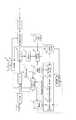
図10は、本発明の実施の形態2に係る表示制御装置の概略構成を示すブロック図である。図10において、図1に示したブロックと同様の動作を行うブロックついては同一の符号を付し、その説明を省略する。 FIG. 10 is a block diagram showing a schematic configuration of the display control apparatus according to
図10において、システム制御部21は、ユーザから蓄積要求を受けると、蓄積再生制御部8に蓄積処理を開始するように指示するとともに、映像復号部22の動作を制御する。これに応じて、映像復号部22は、デマルチプレクサ2からの映像信号を復号して、画素変換部4及び解析部23に出力する。解析部23は、映像復号部22により復号された映像信号の各フレームの画像を、順次DCT等の直行変換手法を用いて、空間的な周波数成分に分解する。そして、空間周波数分解により得られたDCT係数を2乗して、周波数成分毎のエネルギーのヒストグラムを生成する。さらに、解析部23は、各フレームの周波数成分毎のエネルギーヒストグラムから、周波数成分毎のエネルギー平均値及びエネルギー標準偏差σを求め、(エネルギー平均値+2×σ)をエネルギー上限値として算出する。 In FIG. 10, when receiving a storage request from the user, the
予測劣化率記憶部25には、各周波数成分に対応する画像特性の予測劣化率情報が予め格納されている。この予測劣化率情報は、画素変換により画像を拡大した場合に、各周波数成分に対応する画像が劣化する割合を予測するものである。 The predicted deterioration rate storage unit 25 stores in advance prediction deterioration rate information of image characteristics corresponding to each frequency component. This predicted deterioration rate information predicts the rate at which an image corresponding to each frequency component deteriorates when the image is enlarged by pixel conversion.
図11は、図6に示したDCT係数マトリクス上における各周波数成分に対応するDCT係数位置a11〜a88の予測劣化率情報の一例を示す図である。予測劣化率は、予め相当数の画像に対して評価実験を行って決定したものを用いる。 FIG. 11 is a diagram illustrating an example of predicted deterioration rate information of DCT coefficient positions a11 to a88 corresponding to each frequency component on the DCT coefficient matrix illustrated in FIG. The predicted deterioration rate is determined in advance by performing an evaluation experiment on a considerable number of images.
画素数決定部24は、各フレームに対応する周波数成分毎のエネルギー平均値及びエネルギー標準偏差σが算出される度に、予測劣化率記憶部25と閾値記憶部16から周波数成分毎の予測劣化率と劣化判定閾値を取得する。そして、画素数決定部24は、各フレームの全ての周波数成分について、以下の数式(1),(2)を満たす表示画素数を最適表示画素数の予測値とする。 The pixel
エネルギー上限値×(予測劣化率)i=劣化判定閾値・・・(1)
i=最適表示画素数−コンテンツの画素数・・・(2)
数式(2)が示すiは、画素変換によって増加する画素数を表している。予測劣化率は、1画素増加した場合に画像特性がどの程度劣化するかを予測するものである。Energy upper limit value x (predicted deterioration rate)i = deterioration determination threshold value (1)
i = optimum number of display pixels−number of content pixels (2)
I shown in Equation (2) represents the number of pixels that increase due to pixel conversion. The predicted deterioration rate predicts how much the image characteristics deteriorate when the number of pixels increases by one.
画素数記憶部17に記憶される最適表示画素数(予測値)は、1フレーム分の画像解析が終わる度に更新される。ただし、蓄積されたコンテンツの全ての画像フレームをフレーム毎に最適表示画素数(予測値)を求めるのではなく、所定数のフレーム毎に最適表示画素数(予測値)を求めるようにしてもよい。このようにして、コンテンツを蓄積しながら、リアルタイムでコンテンツに最適な表示画素数(予測値)が決定される。なお、算出された最適表示画素数がディスプレイの画素数よりも大きくなる場合は、ディスプレイの画素数を最適表示画素数の予測値とする。 The optimum display pixel number (predicted value) stored in the pixel
コンテンツの蓄積処理が終了した後は、実施の形態1で説明したように最適画素数計算部11により最適表示画素数を決定する。コンテンツ蓄積中に最適表示画素数(予測値)を決定するのに比べて、コンテンツ蓄積処理が終了した後の方が、画像を画素変換して画像特性の評価を行うので、より高精度に最適表示画素数が求められる。 After the content accumulation process is completed, the optimum pixel
図12は、ユーザがコンテンツの再生を要求した場合の処理について説明するための図である。図12において、時刻t10にコンテンツの蓄積が開始され、時刻t12にコンテンツの蓄積が終了するものとする。 FIG. 12 is a diagram for explaining processing when a user requests content reproduction. In FIG. 12, it is assumed that content accumulation starts at time t10 and content accumulation ends at time t12.
図10及び図12を参照して、時刻t10〜t12の期間にコンテンツの蓄積処理を行っている間、画素数決定部24はフレーム毎にリアルタイムに最適表示画素数(予測値)を算出する。時刻t12にコンテンツの蓄積が終了した後は、解析精度をP(1),P(2),P(3),・・・と段階的に高くしながらコンテンツに最適な表示画素数R(1),R(2),R(3),・・・を算出する。 Referring to FIGS. 10 and 12, during the content accumulation process during the period from time t10 to time t12, the pixel
ここで、コンテンツ蓄積処理中の時刻t11に、ユーザがリモコン18を操作して、蓄積されたコンテンツのタイムシフト再生を要求した場合(再生要求C)、システム制御部6は蓄積再生制御部8にコンテンツの再生を指示する。また、システム制御部6は、画素数記憶部17からその時点で算出されている最適表示画素数(予測値)を取得し、画素変換部4に最適表示画素数(予測値)を設定する。蓄積再生制御部8により再生されたコンテンツは、画素変換部4によって最適表示画素数(予測値)に画素変換されてディスプレイに拡大表示される。また、時刻t14に、ユーザが蓄積済みのコンテンツのタイムシフト再生を要求した場合は(再生要求D)、コンテンツはその時点で算出されている最適表示画素数R(1)でディスプレイに拡大表示される。 Here, when the user operates the
このように、コンテンツの蓄積処理中は、他の処理を行う能力に制限があるため、映像復号部22によって復号された映像信号に対して最適表示画素数(予測値)を算出する。そして、蓄積処理が完了した後は、実施の形態1と同様の方法で、解析精度を段階的に高くしながら、蓄積されたコンテンツを画素変換した後に画像特性の評価を行って最適表示画素数を算出する。画素変換には大きな処理負荷がかかるため、この実施の形態2では、コンテンツの蓄積処理中は処理負荷の小さい方法で最適表示画素数(予測値)を求める。 In this way, during the content accumulation process, the ability to perform other processes is limited, so the optimum display pixel number (predicted value) is calculated for the video signal decoded by the
なお、ここではコンテンツの蓄積処理中、及び蓄積処理が完了した後に最適表示画素数を決定する場合について説明したが、例えば受信中の放送コンテンツをリアルタイムに画素変換してディスプレイに拡大表示させる場合にも適用できる。 Here, the case where the optimum display pixel number is determined during the content accumulation process and after the accumulation process is completed has been described. However, for example, when the broadcast content being received is pixel-converted in real time and enlarged on the display. Is also applicable.
(実施の形態3)
この実施の形態3では、ディスプレイの画素数やサイズ(表示領域の大きさ)に応じて、最適表示画素数の決定処理に用いる劣化判定閾値を異なる値とする。(Embodiment 3)
In the third embodiment, the deterioration determination threshold value used for the determination process of the optimum display pixel number is set to a different value according to the number and size of the display (size of the display area).
図13は、本発明の実施の形態3に係る表示制御装置の概略構成を示すブロック図である。図13において、図1に示したブロックと同様の動作を行うブロックついては同一の符号を付し、その説明を省略する。 FIG. 13 is a block diagram showing a schematic configuration of a display control apparatus according to
サイズ・画素数取得部31は、表示制御装置に接続されたディスプレイの画素数及びサイズを取得して、画素数決定部15に出力する。このサイズ・画素数取得部31は、複数のディスプレイが接続されている場合は、複数のディスプレイのうちコンテンツを表示させるディスプレイの画素数及びサイズを取得する。閾値記憶部16には、複数種類のディスプレイに対応した劣化判定閾値が予め格納される。 The size / pixel
図14は、複数種類のディスプレイに対応した劣化判定閾値の一例を示す図である。これらの劣化判定閾値は、評価実験を行う等して予め決めたものである。図14において、ディスプレイの画素数が多いほど、劣化判定閾値は小さな値となっている。また、ディスプレイのサイズ(水平方向の長さ×垂直方向の長さ)が大きいほど、劣化判定閾値は大きな値となっている。 FIG. 14 is a diagram illustrating an example of the deterioration determination threshold corresponding to a plurality of types of displays. These deterioration determination threshold values are predetermined by performing an evaluation experiment or the like. In FIG. 14, the deterioration determination threshold value becomes smaller as the number of pixels of the display increases. In addition, the larger the display size (horizontal length × vertical length) is, the larger the deterioration determination threshold is.
図13に戻って、画素数決定部15は、サイズ・画素数取得部31によって取得されたディスプレイの画素数及びサイズに対応する劣化判定閾値を判定閾値記憶部16から読み出して、最適表示画素数を決定する。 Returning to FIG. 13, the pixel
したがって、表示制御装置がディスプレイと一体型でないセットトップボックス等であっても、ディスプレイの画素数やサイズに合わせた最適表示画素数を決定することができる。また、表示制御装置に複数のディスプレイが接続されている場合でも、コンテンツを表示させるディスプレイの画素数やサイズに合わせた最適表示画素数の決定処理を適宜行うことが可能となる。 Therefore, even if the display control device is a set-top box or the like that is not integrated with the display, it is possible to determine the optimal number of display pixels in accordance with the number of pixels and the size of the display. In addition, even when a plurality of displays are connected to the display control device, it is possible to appropriately perform a process for determining the optimum number of display pixels according to the number of pixels and the size of the display on which content is displayed.
(実施の形態4)
実施の形態4は、最適表示画素数が算出された後に、蓄積コンテンツの圧縮映像信号のヘッダ部に最適表示画素数情報を挿入するように構成したものである。これにより、最適表示画素数が一旦算出された蓄積コンテンツをリムーバブルメディア等に移動(ムーブ)し、その蓄積コンテンツを他の表示制御装置で再生表示させる場合でも、一旦算出された最適表示画素数を再利用することが可能となる。(Embodiment 4)
In the fourth embodiment, after the optimum display pixel number is calculated, the optimum display pixel number information is inserted into the header portion of the compressed video signal of the stored content. As a result, even if the stored content once the optimal display pixel number has been calculated is moved (moved) to a removable medium or the like and the stored content is reproduced and displayed on another display control device, the optimal display pixel number once calculated It can be reused.
図15は、本発明の実施の形態4に係る表示制御装置の概略構成を示すブロック図である。図15において、図13に示したブロックと同様の動作を行うブロックついては同一の符号を付し、その説明を省略する。 FIG. 15 is a block diagram showing a schematic configuration of a display control apparatus according to
画素数情報付加部41は、画素数記憶部17に記憶された最適表示画素数情報を取得してヘッダ情報を作成する。そして、コンテンツ蓄積部9からコンテンツを読み出してデマルチプレックス処理を施して分離した映像信号(MPEG2−video信号)のシーケンスヘッダ部に、作成したヘッダ情報を多重する。画素数情報付加部41は、ヘッダ情報が多重されたMPEG2−TS信号をコンテンツ蓄積部9に蓄積する。コンテンツ蓄積部9に蓄積されるコンテンツには、「最適表示画素数情報」が付加されているか否かを示すフラグが追加される。 The pixel number information adding unit 41 acquires the optimum display pixel number information stored in the pixel
図16は、コンテンツに付加されるヘッダ情報(最適表示画素数情報)の一例を示す図である。図16において、「id」は最適表示画素数ヘッダであることを示す情報(32bit)である。「h_res_opt」は最適表示画素数の水平方向成分を示す情報(32bit)、「v_res_opt」は最適表示画素数の垂直方向成分を示す情報(32bit)である。「h_res_monitor」はディスプレイの画素数の水平方向成分を示す情報(32bit)、「v_res_monitor」はディスプレイの画素数の垂直方向成分を示す情報(32bit)である。「h_siz_monitor」はディスプレイの水平方向の長さを示す情報(32bit)、「v_siz_monitor」はディスプレイの垂直方向の長さを示す情報(32bit)である。また、「scaling_alg」は画素変換アルゴリズムを示す情報(8bit)である。これらのヘッダ情報は、シーケンスヘッダ内に規定されるユーザデータ部に挿入される。MPEG2−video信号及びシーケンスヘッダの詳細は、MPEG2の規格ISO/IEC13818−2に規定されている。 FIG. 16 is a diagram illustrating an example of header information (optimum display pixel number information) added to the content. In FIG. 16, “id” is information (32 bits) indicating that it is an optimal display pixel number header. “H_res_opt” is information (32 bits) indicating the horizontal component of the optimal display pixel number, and “v_res_opt” is information (32 bit) indicating the vertical component of the optimal display pixel number. “H_res_monitor” is information (32 bits) indicating the horizontal component of the number of pixels of the display, and “v_res_monitor” is information (32 bits) indicating the vertical component of the number of pixels of the display. “H_siz_monitor” is information (32 bits) indicating the horizontal length of the display, and “v_siz_monitor” is information (32 bits) indicating the vertical length of the display. “Scaling_alg” is information (8 bits) indicating a pixel conversion algorithm. Such header information is inserted into a user data part defined in the sequence header. Details of the MPEG2-video signal and the sequence header are defined in the MPEG2 standard ISO / IEC13818-2.
次に、ヘッダ情報(最適表示画素数情報)が付加された蓄積コンテンツを再生する場合の動作について説明する。図15に戻って、コンテンツ蓄積部9から読み出されたコンテンツは、デマルチプレクサ2を介して映像復号部42に入力される。映像復号部42は、デマルチプレクサ2を介して受けた映像信号を復号するとともに、映像信号のシーケンスヘッダ部を解析して最適表示画素数情報が付加されているかどうかをチェックする。そして、最適表示画素数情報が検出された場合は、システム制御部43に最適表示画素数情報(図16参照)を出力する。 Next, an operation for reproducing the stored content to which header information (optimum display pixel number information) is added will be described. Returning to FIG. 15, the content read from the
システム制御部43は、映像復号部42から最適表示画素数情報が通知されない場合は、実施の形態3に示した方法で最適表示画素数を決定して、画素変換部4に画素変換を指示する。一方、映像復号部42から最適表示画素数情報が通知された場合は、最適表示画素数情報の内容を解析する。そして、最適表示画素数情報として記述された画素変換アルゴリズムと、画素変換部4の画素変換アルゴリズムとが一致しているかどうかをチェックする。また、最適表示画素数情報として記述されたディスプレイの画素数及びサイズと、表示制御装置に接続されているディスプレイの画素数及びサイズとが一致しているかどうかをチェックする。これらのチェック項目が全て一致している場合は、映像復号部42から通知された最適表示画素数に画素変換を行うように画素変換部4に指示する。いずれか一つでも一致しないチェック項目がある場合は、実施の形態3に示した方法で最適表示画素数を決定して、画素変換部4に画素変換を指示する。 When the optimal display pixel number information is not notified from the
したがって、表示制御装置からコンテンツをコンテンツ蓄積部9に移動(ムーブ)した場合でも、一旦算出された最適表示画素数を再利用することが可能となる。 Therefore, even when the content is moved (moved) from the display control apparatus to the
1 受信部
2 デマルチプレクサ
3 映像復号部
4 画素変換部
5 映像出力部
6 システム制御部
7 蓄積処理部
8 蓄積再生制御部
9 コンテンツ蓄積部
10 画素数決定制御部
11 最適画素数計算部
12 映像復号部
13 画素変換部
14 解析部
15 画素数決定部
16 閾値記憶部
17 画素数記憶部
18 リモコンDESCRIPTION OF
Claims (10)
Translated fromJapanese蓄積部に蓄積された前記映像コンテンツを構成する複数のフレームの画像から解析対象のフレームの画像を抽出して、前記映像コンテンツの画像を拡大した場合の画像特性を解析する解析手段と、
前記解析手段による解析結果に基づいて、前記画像特性の劣化度合いが予め定められた劣化判定基準値を満たすように、前記映像コンテンツの画像を拡大した場合の表示画素数を決定する画素数決定手段と、
再生指示に応答して、前記蓄積部に蓄積された前記映像コンテンツを再生する制御を行う制御手段と、
再生指示を受けた前記映像コンテンツを構成する複数のフレームの画像の画素数を前記画素数決定手段で決定された前記表示画素数に変換して、該映像コンテンツの画像を拡大した拡大画像を前記表示部に出力する画素変換手段とを備え、
前記解析手段は、解析対象のフレーム数を時間経過に応じて段階的に増加させて、前記画像特性を解析する処理を繰り返し実行し、
前記画素数決定手段は、前記解析手段により繰り返し実行される解析処理の結果に基づいて、前記表示画素数を繰り返し決定しなおし、
前記画素変換手段は、前記再生指示を受ける前に表示前記画素数決定手段により決定されている前記表示画素数になるように、前記映像コンテンツを構成する複数のフレームの画像の画素数を変換することを特徴とする表示制御装置。A display control apparatus capable of displaying an enlarged image obtained by enlarging the image of thevideo content on a display unit having a larger number of pixels than the number of pixels of thevideo content,
Analyzing meansfor extracting an image of a frame to be analyzed from a plurality of frames constituting thevideo contentstored in the storage unit and analyzing an image characteristicwhen the image of thevideo content is enlarged ;
Based on the analysis result by said analysismeans, saiddegree of deterioration of imagecharacteristics so as to satisfy thedeterioration determination referencevalue set in advance, the number of pixels determined to determine the number of display pixels inthe case of enlarging the image of thevideo content Means,
Control means for performing control to play back the video content stored in the storage unit in response to a playback instruction;
The enlarged image obtainedby enlarging the image of thevideo content by converting the number of pixelsof the images of theplurality of frames constituting thevideo contentthathas received the reproduction instruction into the number of display pixels determined by the pixel number determination unit. Pixel conversion means for outputting to the display unit,
The analysis means increases the number of frames to be analyzed in a stepwise manner as time elapses, repeatedly executes the process of analyzing the image characteristics,
The pixel number determining means repeatedly determines the display pixel number based on the result of the analysis process repeatedly executed by the analyzing means,
The pixel conversion unit converts the number of pixels of the images of the plurality of frames constituting the video content so that the display pixel number determined by the display pixel number determination unit is obtained before receiving the reproduction instruction. A display control device.
蓄積部に蓄積された前記映像コンテンツを構成する複数フレームの画像から解析対象のフレームの画像を抽出して、該映像コンテンツの画像を拡大した場合の画像特性を解析する解析ステップと、
前記解析ステップによる解析結果に基づいて、前記画像特性の劣化度合いが予め定められた劣化判定基準値を満たすように、前記映像コンテンツの画像を拡大した場合の表示画素数を決定する画素数決定ステップと、
再生指示に応答して、前記蓄積部に蓄積された前記映像コンテンツを再生する制御を行う再生ステップと、
再生指示を受けた前記映像コンテンツを構成する複数のフレームの画像の画素数を前記画素数決定ステップで決定された前記表示画素数に変換して、該映像コンテンツの画像を拡大した拡大画像を前記表示部に出力する画素変換ステップとを備え、
前記解析ステップは、解析対象のフレーム数を時間経過に応じて段階的に増加させて、前記画像特性を解析する処理を繰り返し実行し、
前記画素数決定ステップは、前記解析ステップで繰り返し実行される解析処理の結果に基づいて、前記表示画素数を繰り返し決定しなおし、
前記画素変換ステップは、前記再生指示を受ける前に前記表示画素数決定手段により決定されている前記表示画素数になるように、前記映像コンテンツを構成する複数のフレームの画像の画素数を変換することを特徴とする表示制御方法。A display control method capable of displaying an enlarged image obtained by enlarging an image of the video content on a display unit having a number of pixels larger than the number of pixels of thevideo content,
An analysis stepof extracting an image of a frame to be analyzed from a plurality of frames constituting thevideo contentstored in the storage unit and analyzing an image characteristicwhen the image ofthe video content is enlarged ;
A pixel number determination step for determining the number of display pixelswhen theimage of thevideo contentis enlarged so that thedegree of deterioration of the image characteristics satisfies a predetermineddeterioration criterionvaluebased on the analysis result of the analysis step When,
A playback step for performing control to play back the video content stored in the storage unit in response to a playback instruction;
The enlarged image obtainedby enlarging the image of thevideo content by converting the number of pixelsof the images of theplurality of frames constituting thevideo contentthathas received the reproduction instruction into the display pixel number determined in the pixel number determination step. A pixel conversion step for outputting to the display unit,
In the analysis step, the number of frames to be analyzed is increased step by step with time, and the process of analyzing the image characteristics is repeatedly executed.
The pixel number determination step repeatedly determines the display pixel number based on the result of the analysis process repeatedly executed in the analysis step,
In the pixel conversion step, the number of pixels of a plurality of frames constituting the video content is converted so that the number of display pixels determined by the display pixel number determination unit is obtained before receiving the reproduction instruction. A display control method.
Priority Applications (2)
| Application Number | Priority Date | Filing Date | Title |
|---|---|---|---|
| JP2007002055AJP4267036B2 (en) | 2007-01-10 | 2007-01-10 | Display control apparatus and display control method |
| US11/970,472US8115789B2 (en) | 2007-01-10 | 2008-01-07 | Display control apparatus and method for enlarging image of content and displaying enlarged image |
Applications Claiming Priority (1)
| Application Number | Priority Date | Filing Date | Title |
|---|---|---|---|
| JP2007002055AJP4267036B2 (en) | 2007-01-10 | 2007-01-10 | Display control apparatus and display control method |
Publications (2)
| Publication Number | Publication Date |
|---|---|
| JP2008172392A JP2008172392A (en) | 2008-07-24 |
| JP4267036B2true JP4267036B2 (en) | 2009-05-27 |
Family
ID=39593883
Family Applications (1)
| Application Number | Title | Priority Date | Filing Date |
|---|---|---|---|
| JP2007002055AExpired - Fee RelatedJP4267036B2 (en) | 2007-01-10 | 2007-01-10 | Display control apparatus and display control method |
Country Status (2)
| Country | Link |
|---|---|
| US (1) | US8115789B2 (en) |
| JP (1) | JP4267036B2 (en) |
Families Citing this family (4)
| Publication number | Priority date | Publication date | Assignee | Title |
|---|---|---|---|---|
| JP5471072B2 (en)* | 2009-06-26 | 2014-04-16 | 富士通株式会社 | Display test apparatus, display test program, and display test method |
| JP6073664B2 (en) | 2012-12-07 | 2017-02-01 | 株式会社東芝 | Content reproduction apparatus and content reproduction program |
| JP2014187533A (en)* | 2013-03-22 | 2014-10-02 | Casio Comput Co Ltd | Projection control apparatus, projection apparatus, image output apparatus, and projection control system |
| JP6255760B2 (en)* | 2013-07-16 | 2018-01-10 | ソニー株式会社 | Information processing apparatus, information recording medium, information processing method, and program |
Family Cites Families (9)
| Publication number | Priority date | Publication date | Assignee | Title |
|---|---|---|---|---|
| JP3922472B2 (en) | 1997-06-12 | 2007-05-30 | ソニー株式会社 | Image conversion apparatus, image conversion method, and recording medium |
| JP3931942B2 (en)* | 1999-02-02 | 2007-06-20 | 富士フイルム株式会社 | Image file device |
| JP2001128062A (en) | 1999-10-29 | 2001-05-11 | Matsushita Electric Ind Co Ltd | Image generation apparatus and image generation method |
| JP2004173078A (en)* | 2002-11-21 | 2004-06-17 | Canon Inc | Image processing device |
| DE10354556B4 (en)* | 2002-11-25 | 2008-10-09 | Samsung Electronics Co., Ltd., Suwon | Apparatus and method for displaying images in a mobile terminal |
| JP2005211159A (en)* | 2004-01-27 | 2005-08-11 | Fujinon Corp | Electronic endoscope apparatus |
| US20080123925A1 (en)* | 2005-02-15 | 2008-05-29 | Sumiya Nagatsuka | Medical Imaging System |
| JP2006303707A (en) | 2005-04-18 | 2006-11-02 | Canon Inc | Image processing apparatus and image processing method |
| JP2007034733A (en)* | 2005-07-27 | 2007-02-08 | Toshiba Corp | Object region detection apparatus, method and program |
- 2007
- 2007-01-10JPJP2007002055Apatent/JP4267036B2/ennot_activeExpired - Fee Related
- 2008
- 2008-01-07USUS11/970,472patent/US8115789B2/ennot_activeExpired - Fee Related
Also Published As
| Publication number | Publication date |
|---|---|
| JP2008172392A (en) | 2008-07-24 |
| US20080165191A1 (en) | 2008-07-10 |
| US8115789B2 (en) | 2012-02-14 |
Similar Documents
| Publication | Publication Date | Title |
|---|---|---|
| JP4444354B2 (en) | Image processing apparatus and image processing method | |
| US20100166081A1 (en) | Video stream processing apparatus and control method, program and recording medium for the same | |
| JP4462823B2 (en) | Image signal processing apparatus and processing method, coefficient data generating apparatus and generating method used therefor, and program for executing each method | |
| US8559526B2 (en) | Apparatus and method for processing decoded images | |
| US7755701B2 (en) | Image processing apparatus, image processing method, and program | |
| JP4267036B2 (en) | Display control apparatus and display control method | |
| JP4513873B2 (en) | Video processing apparatus and video processing method | |
| EP1416723B1 (en) | Method for resizing an image using the inverse discrete cosine transform | |
| US8224120B2 (en) | Image signal processing apparatus and image signal processing method | |
| KR101372639B1 (en) | Method and apparatus for commercial detecting | |
| JP4735696B2 (en) | Image processing apparatus, image processing method, and program | |
| JP2010087871A (en) | Video image processor and method of processing video image | |
| JP2010041519A (en) | Frame rate conversion apparatus, frame rate conversion method, television receiver, frame rate conversion program, and recording medium with the program recorded thereon | |
| KR100930436B1 (en) | Image Resizing Method Using Discrete Cosine Inverse Transform | |
| CN100592778C (en) | Recording and playback apparatus, and recording and playback method, recording apparatus and recording method, playback apparatus and playback method | |
| JP4991884B2 (en) | Image processing apparatus and image processing method | |
| US20050259752A1 (en) | Apparatus for and method of image processing and output, and computer product | |
| JP7641516B2 (en) | Image processing method, image processing device, and program | |
| JP2011139193A (en) | Recording device and recording method | |
| JP4184223B2 (en) | Transcoder | |
| JP2011061709A (en) | Video processing apparatus and method | |
| JP2010045607A (en) | Image processing apparatus and method | |
| JP2008519481A (en) | Data processing system and method, program element, and computer-readable medium | |
| JP2009055231A (en) | Movie display processing device, movie data multiplexing device, movie display method, computer program, and recording medium | |
| JP2001157112A (en) | Telecine device, video signal processor and video signal transmission system |
Legal Events
| Date | Code | Title | Description |
|---|---|---|---|
| A977 | Report on retrieval | Free format text:JAPANESE INTERMEDIATE CODE: A971007 Effective date:20081113 | |
| A131 | Notification of reasons for refusal | Free format text:JAPANESE INTERMEDIATE CODE: A131 Effective date:20081125 | |
| A521 | Request for written amendment filed | Free format text:JAPANESE INTERMEDIATE CODE: A523 Effective date:20090121 | |
| TRDD | Decision of grant or rejection written | ||
| A01 | Written decision to grant a patent or to grant a registration (utility model) | Free format text:JAPANESE INTERMEDIATE CODE: A01 Effective date:20090210 | |
| A01 | Written decision to grant a patent or to grant a registration (utility model) | Free format text:JAPANESE INTERMEDIATE CODE: A01 | |
| A61 | First payment of annual fees (during grant procedure) | Free format text:JAPANESE INTERMEDIATE CODE: A61 Effective date:20090217 | |
| R150 | Certificate of patent or registration of utility model | Ref document number:4267036 Country of ref document:JP Free format text:JAPANESE INTERMEDIATE CODE: R150 Free format text:JAPANESE INTERMEDIATE CODE: R150 | |
| FPAY | Renewal fee payment (event date is renewal date of database) | Free format text:PAYMENT UNTIL: 20120227 Year of fee payment:3 | |
| FPAY | Renewal fee payment (event date is renewal date of database) | Free format text:PAYMENT UNTIL: 20130227 Year of fee payment:4 | |
| FPAY | Renewal fee payment (event date is renewal date of database) | Free format text:PAYMENT UNTIL: 20140227 Year of fee payment:5 | |
| LAPS | Cancellation because of no payment of annual fees |