JP4266936B2 - IP telephone apparatus and IP telephone connection method - Google Patents
IP telephone apparatus and IP telephone connection methodDownload PDFInfo
- Publication number
- JP4266936B2 JP4266936B2JP2005017485AJP2005017485AJP4266936B2JP 4266936 B2JP4266936 B2JP 4266936B2JP 2005017485 AJP2005017485 AJP 2005017485AJP 2005017485 AJP2005017485 AJP 2005017485AJP 4266936 B2JP4266936 B2JP 4266936B2
- Authority
- JP
- Japan
- Prior art keywords
- telephone
- line
- call
- control circuit
- switching
- Prior art date
- Legal status (The legal status is an assumption and is not a legal conclusion. Google has not performed a legal analysis and makes no representation as to the accuracy of the status listed.)
- Expired - Fee Related
Links
- 238000000034methodMethods0.000titleclaimsdescription34
- 238000004891communicationMethods0.000claimsdescription14
- 230000005540biological transmissionEffects0.000claimsdescription7
- 239000000284extractSubstances0.000claimsdescription7
- 238000012544monitoring processMethods0.000claimsdescription5
- 238000005516engineering processMethods0.000description6
- 238000010586diagramMethods0.000description2
- 230000005236sound signalEffects0.000description2
- 230000000694effectsEffects0.000description1
- 230000010365information processingEffects0.000description1
Images


Landscapes
- Telephonic Communication Services (AREA)
Description
Translated fromJapanese本発明は、IP電話装置およびIP電話の接続方法に関し、特に公衆回線を介して受信する呼を適切にIP電話回線に接続するIP電話装置およびIP電話の接続方法に関する。 The present invention relates to an IP telephone apparatus and an IP telephone connection method, and more particularly to an IP telephone apparatus and an IP telephone connection method for appropriately connecting a call received via a public line to an IP telephone line.
IPネットワークの普及に伴って、そのIPネットワークを介して電話(送受話)をすることを可能にするサービス(以下、IP電話サービスと呼ぶ。)が提供されるようになってきている(例えば、特許文献1参照)。IP電話サービスは、VoIP(Voice Over IP)技術によって実現されている。VoIP技術とは、音声を音声デジタルデータに変換した後、IPパケット化して、そのIPネットワークを介して転送する技術である。IP電話サービスにVoIP技術を適用することによって、音声通話とデータ通信とを統合して扱うことが可能になる。そのため、VoIP技術を用いたIP電話サービスは、通話にかかる料金を固定的に提供することができ、ユーザの負担する通信コストの削減に適している。 With the widespread use of IP networks, services (hereinafter referred to as IP telephone services) that enable telephone calls (transmission / reception) via the IP networks have come to be provided (for example, Patent Document 1). The IP telephone service is realized by VoIP (Voice Over IP) technology. The VoIP technology is a technology in which voice is converted into voice digital data, then converted into IP packets, and transferred via the IP network. By applying the VoIP technology to the IP telephone service, it becomes possible to handle voice call and data communication in an integrated manner. For this reason, the IP telephone service using the VoIP technology can provide a fixed charge for a call, and is suitable for reducing the communication cost borne by the user.
ユーザが、IP電話サービスを受けるためには、IPネットワークに接続され、VoIP技術に対応した通信制御が可能な端末(例えば、IP電話アダプタ)が必要である。また、ユーザは、IP電話事業者から提供されるIP電話用の電話番号(サービス番号「050」で始まる電話番号、以下、IP電話番号と呼ぶ。)を保有し、そのIP電話番号を使用してIP電話サービスを利用している。 In order for a user to receive an IP phone service, a terminal (for example, an IP phone adapter) connected to an IP network and capable of communication control corresponding to the VoIP technology is required. In addition, the user has a telephone number for an IP telephone provided by an IP telephone carrier (a telephone number starting with a service number “050”, hereinafter referred to as an IP telephone number) and uses the IP telephone number. IP phone service is used.
つまり、現在提供されているIP電話サービスを受ける場合、IP電話アダプタを備えた電話機を使用して、相手先のIP電話番号に向けて発信を行うことでIPネットワークを介して音声通話が行えるようになる。IP電話の電話番号と公衆回線網の電話番号が異なるため、IP電話同士で通話したい場合は、IP電話用の電話番号にダイヤルすることが要求される。相手先がIP電話用の電話番号を保有しているかどうかが不明な場合、通話料の発生する公衆回線経由で電話をかけなければならなかった。 In other words, when receiving an IP telephone service that is currently provided, it is possible to make a voice call over an IP network by making a call to the IP telephone number of the other party using a telephone equipped with an IP telephone adapter. become. Since the telephone number of the IP telephone is different from the telephone number of the public line network, it is required to dial the telephone number for the IP telephone when calling between IP telephones. When it is unclear whether the other party has a telephone number for IP telephone, it was necessary to make a call via a public line that generates a call charge.
本発明が解決しようとする課題は、公衆回線の電話番号でダイヤルしてもIP電話同士の通話ができるIP電話装置を提供することにある。 The problem to be solved by the present invention is to provide an IP telephone apparatus that can make a call between IP telephones even when dialing with a telephone number of a public line.
以下に、[発明を実施するための最良の形態]で使用される番号を用いて、課題を解決するための手段を説明する。これらの番号は、[特許請求の範囲]の記載と[発明を実施するための最良の形態]との対応関係を明らかにするために付加されたものである。ただし、それらの番号を、[特許請求の範囲]に記載されている発明の技術的範囲の解釈に用いてはならない。 The means for solving the problem will be described below using the numbers used in [Best Mode for Carrying Out the Invention]. These numbers are added to clarify the correspondence between the description of [Claims] and [Best Mode for Carrying Out the Invention]. However, these numbers should not be used to interpret the technical scope of the invention described in [Claims].
上記課題を解決するために、公衆回線(6)を介して送信される呼信号を受信したときに、前記呼信号に対応して発信側電話機(4または2)の電話番号を特定する番号識別回路(12、32)と、受信側電話機(2または4)に接続され、前記公衆回線(6)とIP電話回線(5)との一方を選択的に用いて前記発信側電話機(4または2)と前記受信側電話機(2または4)とを接続する制御部(11、31)とを具備するIP電話装置(IP電話アダプタ)を構成する。そのIP電話装置において、前記制御部(11、31)は、特定された前記電話番号のサービス番号を抽出し、前記サービス番号が、前記IP電話回線(5)を介して実行される音声通話に対応するサービス番号であるときに、前記発信側電話機(4または2)と前記受信側電話機(2または4)とを前記IP電話回線(5)を介して接続する。ここで、そのIP電話装置において、前記番号識別回路(12、32)は、発信者番号通知サービスに対応して前記発信側電話機(4または2)の前記電話番号を特定する構成であることが好ましい。また、そのIP電話装置において、前記制御部(11、31)は、前記呼信号に応答して、前記発信側電話機(4または2)との通話回線を確立し、前記番号識別回路(12、32)は、前記通話回線を介して送信される情報から、前記発信側電話機(4または2)の電話番号を特定して前記制御部(11、31)に供給する構成であっても良い。 In order to solve the above-mentioned problem, when a call signal transmitted through the public line (6) is received, a number identification that specifies the telephone number of the calling telephone (4 or 2) corresponding to the call signal Connected to the circuit (12, 32) and the receiving telephone (2 or 4), and selectively uses one of the public line (6) and the IP telephone line (5) to call the calling telephone (4 or 2). ) And the control unit (11, 31) for connecting the receiving telephone (2 or 4). In the IP telephone apparatus, the control unit (11, 31) extracts the service number of the specified telephone number, and the service number is used for a voice call executed via the IP telephone line (5). When the service number is the corresponding service number, the calling side telephone (4 or 2) and the receiving side telephone (2 or 4) are connected via the IP telephone line (5). Here, in the IP telephone apparatus, the number identification circuit (12, 32) is configured to identify the telephone number of the caller telephone (4 or 2) corresponding to the caller ID notification service. preferable. In the IP telephone apparatus, the control unit (11, 31) establishes a communication line with the caller telephone (4 or 2) in response to the call signal, and the number identification circuit (12, 32) may be configured to identify the telephone number of the caller telephone (4 or 2) from the information transmitted via the telephone line and supply it to the controller (11, 31).
そのIP電話装置において、前記制御部(11、31)は、中央制御回路(15、35)と、音声信号を、前記IP電話回線(5)に対応して送受信可能なデジタルデータに変換するIP電話制御回路(14、34)と、前記IP電話制御回路(14、34)に接続され、前記IP電話制御回路(14、34)と前記IP電話回線(5)との通信を制御する回線制御回路(13、33)とを含むように構成されていることが好ましい。そして、前記中央制御回路(15、35)は、前記番号識別回路(12、32)から供給される前記電話番号から前記サービス番号を抽出し、抽出した前記サービス番号が前記IP電話回線(5)を介して実行される音声通話に対応するサービス番号であるときに、前記IP電話制御回路(14、34)に、前記発信側電話機(4または2)へ前記IP電話回線(5)を介して発信を行うことを指示する。前記IP電話制御回路(14、34)は、前記指示に応答して、前記電話番号を用いて前記発信側電話機(4または2)に回線切替用呼信号を送信する。 In the IP telephone apparatus, the control unit (11, 31) and the central control circuit (15, 35) and IP for converting voice signals into digital data that can be transmitted / received corresponding to the IP telephone line (5). Line control connected to the telephone control circuit (14, 34) and the IP telephone control circuit (14, 34) to control communication between the IP telephone control circuit (14, 34) and the IP telephone line (5) The circuit (13, 33) is preferably included. The central control circuit (15, 35) extracts the service number from the telephone number supplied from the number identification circuit (12, 32), and the extracted service number is the IP telephone line (5). When the service number corresponds to a voice call performed via the IP telephone control circuit (14, 34), the caller side telephone (4 or 2) is routed via the IP telephone line (5). Instruct to make a call. In response to the instruction, the IP telephone control circuit (14, 34) transmits a line switching call signal to the calling telephone (4 or 2) using the telephone number.
そのIP電話装置において、前記制御部(11、31)は、さらに、前記受信側電話機(2または4)と接続する回線を、前記公衆回線(6)から前記IP電話回線(5)に切替える切替回路(17、37)と、前記切替回路(17、37)に接続され、前記切替回路(17、37)を介して供給される音声信号を前記IP電話制御回路(14、34)に出力する電話機制御回路(16、36)とを含む構成であっても良い。その場合、前記中央制御部(11、31)は、前記回線切替用呼信号に対する応答を監視し、前記回線切替用呼信号に対する応答に基づいて、前記回線切替え命令を生成し、前記切替回路(17、37)は、前記回線切替え命令に応答して、前記受信側電話機(2または4)と接続する回線を、前記公衆回線(6)から前記IP電話回線(5)に切替える。 In the IP telephone apparatus, the control unit (11, 31) further switches the line connected to the receiving telephone (2 or 4) from the public line (6) to the IP telephone line (5). An audio signal connected to the circuit (17, 37) and the switching circuit (17, 37) and supplied via the switching circuit (17, 37) is output to the IP telephone control circuit (14, 34). The telephone control circuit (16, 36) may be included. In that case, the central control unit (11, 31) monitors a response to the line switching call signal, generates the line switching command based on the response to the line switching call signal, and generates the switching circuit ( 17 and 37), in response to the line switching command, switches the line connected to the receiving telephone (2 or 4) from the public line (6) to the IP telephone line (5).
そのIP電話装置において、前記IP電話制御部(11、31)は、前記公衆回線(6)を介して他のIP電話装置に発信を行っているときに、前記他のIP電話装置から送信される回線切替用呼信号である他の回線切替用呼信号の受信を監視する。そして、前記他の回線切替用呼信号を受信したときに、前記他のIP電話装置への発信に用いたパスを、前記IP電話回線(5)に対応したパスに切り替える構成であることが好ましい。 In the IP telephone apparatus, the IP telephone control unit (11, 31) is transmitted from the other IP telephone apparatus when making a call to the other IP telephone apparatus via the public line (6). The reception of another line switching call signal that is a line switching call signal is monitored. When the other line switching call signal is received, the path used for outgoing calls to the other IP telephone apparatus is preferably switched to a path corresponding to the IP telephone line (5). .
そのIP電話装置において、前記IP電話制御部(11、31)は、前記他のIP電話装置への発信に用いたパスを、前記IP電話回線(5)に対応したパスに切り替えた後、前記公衆回線(6)を介して出力した前記他のIP電話装置への発信を放棄する構成であることが好ましい。 In the IP telephone apparatus, the IP telephone control unit (11, 31) switches the path used for outgoing calls to the other IP telephone apparatus to a path corresponding to the IP telephone line (5), and then It is preferable that the transmission to the other IP telephone apparatus output via the public line (6) is abandoned.
さらに、そのIP電話装置において、前記番号識別回路(12、32)は、前記公衆回線(6)を介して他のIP電話装置へ発信を行う。そのときに、前記他のIP電話装置との通話回線が確立されたことに応答して、前記IP電話装置に接続される電話機の電話番号を前記他のIP電話装置に送信する構成であっても良い。 Further, in the IP telephone apparatus, the number identification circuit (12, 32) makes a call to another IP telephone apparatus via the public line (6). At that time, the telephone number of the telephone connected to the IP telephone apparatus is transmitted to the other IP telephone apparatus in response to the establishment of a communication line with the other IP telephone apparatus. Also good.
さらに、上記課題を解決するために、以下の方法でIP電話を接続する。その接続方法は、
[a]公衆回線(6)を介して送信される呼信号を受信するステップと、
[b]前記呼信号に対応して発信側電話機(4または2)の電話番号を特定するステップと、
[c]前記公衆回線(6)とIP電話回線(5)との一方を選択的に用いて前記発信側電話機(4または2)と受信側電話機(2または4)とを接続するステップと、
[d]特定された前記電話番号のサービス番号を抽出し、前記サービス番号が、前記IP電話回線(5)を介して実行される音声通話に対応するサービス番号であるときに、前記発信側電話機(4または2)と前記受信側電話機(2または4)とを前記IP電話回線(5)を介して接続するステップを具備するIP電話の接続方法であることが好ましい。Further, in order to solve the above problem, an IP phone is connected by the following method. The connection method is
[A] receiving a call signal transmitted via the public line (6);
[B] identifying the telephone number of the calling telephone (4 or 2) in response to the call signal;
[C] connecting the calling telephone (4 or 2) and the receiving telephone (2 or 4) selectively using one of the public line (6) and the IP telephone line (5);
[D] A service number of the identified telephone number is extracted, and when the service number is a service number corresponding to a voice call executed via the IP telephone line (5), the calling side telephone Preferably, the IP telephone connection method comprises a step of connecting (4 or 2) and the receiving telephone (2 or 4) via the IP telephone line (5).
そのIP電話の接続方法において、前記[b]ステップは、発信者番号通知サービスに対応して前記発信側電話機(4または2)の前記電話番号を特定するステップを具備するIP電話の接続方法であることが好ましい。また、そのIP電話の接続方法において、前記[b]ステップは、前記呼信号に応答して、前記発信側電話機(4または2)との通話回線を確立するステップと、前記通話回線を介して送信される情報から、前記発信側電話機(4または2)の電話番号を特定するステップを具備するIP電話の接続方法出会っても良い。 In the IP telephone connection method, the step [b] is an IP telephone connection method comprising a step of identifying the telephone number of the calling telephone (4 or 2) in correspondence with a caller ID notification service. Preferably there is. Further, in the IP telephone connection method, the [b] step includes the steps of establishing a communication line with the caller telephone (4 or 2) in response to the call signal, An IP telephone connection method comprising the step of identifying the telephone number of the calling telephone (4 or 2) from the transmitted information may be met.
さらに、そのIP電話の接続方法において、
前記[d]ステップは、
前記電話番号から前記サービス番号を抽出し、抽出した前記サービス番号が前記IP電話回線(5)を介して実行される音声通話に対応するサービス番号であるときに、前記発信側電話機(4または2)へ前記IP電話回線(5)を介して発信を行うことを指示するステップと、
前記指示に応答して、前記電話番号を用いて前記発信側電話機(4または2)に回線切替用呼信号を送信するステップと、
前記回線切替用呼信号に対する応答を監視し、前記回線切替用呼信号に対する応答に基づいて、前記回線切替え命令を生成するステップと、
前記回線切替え命令に応答して、前記受信側電話機(2または4)と接続する回線を、前記公衆回線(6)から前記IP電話回線(5)に切替えるステップを具備するIP電話の接続方法であることが好ましい。Furthermore, in the connection method of the IP phone,
The [d] step includes
The service number is extracted from the telephone number, and when the extracted service number is a service number corresponding to a voice call executed via the IP telephone line (5), the calling side telephone (4 or 2) Instructing to make a call via the IP telephone line (5),
In response to the instruction, transmitting a line switching call signal to the calling telephone (4 or 2) using the telephone number;
Monitoring a response to the line switching call signal, and generating the line switching command based on the response to the line switching call signal;
An IP telephone connection method comprising a step of switching a line connected to the receiving telephone (2 or 4) from the public line (6) to the IP telephone line (5) in response to the line switching command. Preferably there is.
そのIP電話の接続方法において、さらに、
[e]前記公衆回線(6)を介して他のIP電話装置に発信を行っているときに、前記他のIP電話装置から送信される回線切替用呼信号である他の回線切替用呼信号の受信を監視し、前記他の回線切替用呼信号を受信したときに、前記他のIP電話装置への発信に用いたパスを、前記IP電話回線(5)に対応したパスに切り替えるステップを具備するIP電話の接続方法であることが好ましい。In the IP telephone connection method,
[E] Other line switching call signal which is a line switching call signal transmitted from the other IP telephone apparatus when making a call to the other IP telephone apparatus via the public line (6) And when the other line switching call signal is received, the path used for calling the other IP telephone apparatus is switched to a path corresponding to the IP telephone line (5). It is preferable that the IP telephone connection method is provided.
そのIP電話の接続方法において、前記[e]ステップは、前記他のIP電話装置への発信に用いたパスを、前記IP電話回線(5)に対応したパスに切り替えた後、前記公衆回線(6)を介して出力した前記他のIP電話装置への発信を放棄するステップを具備するIP電話の接続方法であることが好ましい。 In the IP telephone connection method, the [e] step switches the path used for calling to the other IP telephone apparatus to a path corresponding to the IP telephone line (5), and then the public line ( 6) It is preferable that the IP telephone connection method includes the step of abandoning the outgoing call to the other IP telephone apparatus output via 6).
そのIP電話の接続方法において、さらに、
[f]前記公衆回線(6)を介して他のIP電話装置へ発信を行うときに、前記他のIP電話装置との通話回線の確立に応答して、電話番号を前記他のIP電話装置に送信するステップを具備するIP電話の接続方法であることが好ましい。In the IP telephone connection method,
[F] When making a call to another IP telephone apparatus via the public line (6), the telephone number is assigned to the other IP telephone apparatus in response to establishment of a telephone line with the other IP telephone apparatus. Preferably, the IP telephone connection method includes the step of transmitting to the IP telephone.
本発明のよると、公衆回線の電話番号でダイヤルしてもIP電話同士の通話ができるIP電話装置を提供することができる。言いかえると、本発明は、発信先のIP電話の使用の可否を知らなくともIP電話同士の通話に切り替え可能なので、利便性を向上することができる。
また、本発明は通話料が発生するIP電話対公衆回線の通話を通話料金が発生しないIP電話同士の通話に切り替えるので、通話料金を抑えることができる。
また、本発明は発信者番号通知を利用して、IP電話使用の有無を判断しているので、特別な回路構成を取らなくとも容易に実現することができる。
さらに、発信者番号サービスに加入していない場合でも、発信がわに番号の通知を要求することでIP電話同士の通話が可能になる。According to the present invention, it is possible to provide an IP telephone apparatus that can make a call between IP telephones even if dialing with a telephone number of a public line. In other words, according to the present invention, it is possible to switch to a call between IP phones without knowing whether or not the destination IP phone can be used, so that convenience can be improved.
Further, according to the present invention, since the IP phone-to-public line call that generates a call charge is switched to a call between IP telephones that do not generate a call charge, the call charge can be suppressed.
In addition, since the present invention determines whether or not an IP telephone is used by using caller ID notification, it can be easily realized without taking a special circuit configuration.
Further, even when the caller ID service is not subscribed, it is possible to make a call between IP phones by requesting notification of the outgoing call number.
[第1の実施形態の構成]
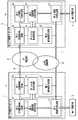
以下に、図面を参照して本発明を実施するための形態について説明を行う。図1は、本実施の形態の構成を示すブロック図である。図1を参照すると、本実施の形態におけるIP電話システムは、第1IP電話アダプタ1と、第1電話機2と、第2IP電話アダプタ3と、第2電話機4とを含んで構成されている。第1IP電話アダプタ1と第2IP電話アダプタ3とは同様の構成であり、それぞれが電話をかける機能とかかってきた電話を受ける機能とを有している。従って、以下の実施に形態において、第1IP電話アダプタ1と第1電話機2とが受信側ブロックであり、第2IP電話アダプタ3と第2電話機4が発信側ブロックである場合を例示して説明を行う。また、図1に示されているように、第1IP電話アダプタ1と第2IP電話アダプタ3とは、IP電話網5を介して通話可能に接続されている。同様に、第1IP電話アダプタ1と第2IP電話アダプタ3とは公衆回線網6を介して通話可能に接続されいている。ここで、IP電話網5は、呼制御サーバ、ルータ等を含むIP電話網を示している。また、公衆回線網6は、交換機を含む電話機網であり、発信者番号通知サービスを受けている回線を示してる。[Configuration of First Embodiment]
Hereinafter, embodiments for carrying out the present invention will be described with reference to the drawings. FIG. 1 is a block diagram showing the configuration of the present embodiment. Referring to FIG. 1, the IP telephone system according to the present embodiment includes a first IP telephone adapter 1, a first telephone 2, a second
第1IP電話アダプタ1と第2IP電話アダプタ3は、IP電話網5を介して音声通話を実行するための、情報処理を行う接続装置である。図1に示されているように、第1IP電話アダプタ1は、第1制御部11と、第1番号識別回路12とを含んで構成されている。その第1制御部11は、第1回線制御回路13と、第1IP電話制御回路14と、第1中央制御回路15と、第1電話機制御回路16と、第1切替制御回路17とを含んで構成されている。同様に、第2IP電話アダプタ3は、第2制御部31と第2番号識別回路32とを含んで構成されている。その、第2制御部31は、第2回線制御回路33と、第2IP電話制御回路34と、第2中央制御回路35と、第2電話機制御回路36と、第2切替制御回路37とを含んで構成されている。ここで、第1IP電話アダプタ1と第2IP電話アダプタ3とは、同様の構成であり、それぞれは互いに置換可能である。従って、以下の構成の説明においては、第1IP電話アダプタ1を主として説明を行う。また、第1電話機2と第2電話機4とは同様の構成であり、それぞれは互いに置換可能である。 The first IP telephone adapter 1 and the second
第1番号識別回路12(または第2番号識別回路32)は、公衆回線網6を介して着信があった場合、その着信に対応して発信側の電話番号の識別をする番号識別回路である。第1の実施の形態における第1番号識別回路12は、発信者番号通知サービスの処理手順で公衆回線からの発信者番号を引き取ることで、発信側の電話番号を特定している。第1制御部11(または第2制御部31)は、音声通話に使用する回線の切替えを制御する制御ブロックである。上述したように、第1制御部11は、複数の機能ブロック(13〜17)を含んで構成されている。 The first number identification circuit 12 (or the second number identification circuit 32) is a number identification circuit that identifies the telephone number on the caller side in response to an incoming call via the public line network 6. . The first
第1回線制御回路13(または第2回線制御回路33)は、電話機とIP電話網5との接続制御をする制御回路である。第1回線制御回路13は、接続形態が異なる複数のIP電話網が存在する場合、各々に適用可能な回路を含んで構成されていることが好ましい。第1IP電話制御回路14(または第2IP電話制御回路34)は、IP電話の相手先に電話をかけたり、通話が終ったあとに電話を切ったりするための呼制御プロトコルの制御とIPパケット化された音声データの送受信制御をする制御回路である。第1IP電話制御回路14は、IP電話の呼を同時に2つ以上処理可能な機能を含んで構成されていることが好ましい。第1IP電話制御回路14は、その機能を用いることで第1電話機制御回路16と接続する呼を自由に切替できるものである。 The first line control circuit 13 (or the second line control circuit 33) is a control circuit that controls connection between the telephone and the
第1中央制御回路15(または第2中央制御回路35)は、各回路(12、13、14、16、17)からの情報を元に各回路に処理命令をする制御回路である。第1電話機制御回路16(または第2電話機制御回路36)は、IP電話使用時に第1電話機2(または第2電話機4)の制御/音声の送受信をする制御回路である。第1切替制御回路17(または第2切替制御回路37)は、第1電話機2(または第2電話機4)の接続をIP電話使用時は、第1電話機制御回路16(または第2電話機制御回路36) に、公衆回線使用時は公衆回線網6に切替える切替え回路である。 The first central control circuit 15 (or the second central control circuit 35) is a control circuit that gives a processing instruction to each circuit based on information from each circuit (12, 13, 14, 16, 17). The first telephone control circuit 16 (or the second telephone control circuit 36) is a control circuit that performs control / sound transmission / reception of the first telephone 2 (or the second telephone 4) when using the IP telephone. The first switching control circuit 17 (or the second switching control circuit 37) is configured to connect the first telephone 2 (or the second telephone 4) to the first telephone control circuit 16 (or the second telephone control circuit) when using the IP telephone. 36) A switching circuit for switching to the public line network 6 when the public line is used.
図1を参照すると、第1電話機2と第1IP電話アダプタ1とは互いに接続され、より詳細には、第1電話機2は、第1切替制御回路17に接続されている。その第1切替制御回路17は、公衆回線網6に接続されている。また、図1に示されているように、第1番号識別回路12は公衆回線網6に接続され、公衆回線網6を経由して供給される信号は、第1番号識別回路12と第1切替制御回路17との各々に供給されている。また第1切替制御回路17は、第1電話機制御回路16に接続されている。第1切替制御回路17は、第1中央制御回路15から供給される命令に応答して、第1電話機2が音声通話に用いる回線の切替えを実行している。図1に示されているように、第1電話機制御回路16は、第1IP電話制御回路14に接続されている。その第1IP電話制御回路14は、第1回線制御回路13に接続され、第1回線制御回路13を介してIP電話網5に接続されている。また、第1中央制御回路15と上述の各回路(第1番号識別回路12、第1回線制御回路13、第1IP電話制御回路14、第1電話機制御回路16、第1切替制御回路17)とは互いに接続されている。 Referring to FIG. 1, the first telephone 2 and the first IP telephone adapter 1 are connected to each other, and more specifically, the first telephone 2 is connected to the first
[第1の実施形態の動作]
以下に、図面を参照して本実施の形態の動作について説明を行う。図2は、本実施の形態の動作を例示するフローチャートである。図2に示されている動作は、第2電話機4が、第1電話機2へ電話をかけることにより開始する。ステップS101において、第2電話機4に接続される第2IP電話アダプタ3は、公衆回線網6を介して第1電話機2へ呼信号(第1電話機2の呼出音を鳴らすための信号)を送信する。第2IP電話制御回路34が第1IP電話アダプタ1に発信をする時、第2IP電話アダプタ3の第2切替制御回路37は、第2電話機4と第2電話機制御回路36とを接続する。従って、第1IP電話アダプタ1からの着信を受ける時、第2IP電話アダプタ3と接続されている第2電話機4は、第2電話機制御回路36と接続された状態になっているものとする。[Operation of First Embodiment]
The operation of the present embodiment will be described below with reference to the drawings. FIG. 2 is a flowchart illustrating the operation of this embodiment. The operation shown in FIG. 2 starts when the
ステップS102において、第1IP電話アダプタ1は、公衆回線網6を経由して第2電話機4からの呼信号を受信する。ステップS103おいて、第1IP電話アダプタ1の第1番号識別回路12は、受信した呼信号に応答して発信側の電話番号(第2電話機4に割当てられている電話番号)を特定する。 In step S102, the first IP telephone adapter 1 receives a call signal from the
ステップS104において、第1番号識別回路12は、特定した発信側電話番号を第1中央制御回路15に出力する。第1中央制御回路15は、この第1番号識別回路12から供給される電話番号からサービス番号(例えば、11桁の電話番号の最初の3桁の番号)を抽出する。第1中央制御回路15は、そのサービス番号が、IP電話サービスに対応する番号(各事業者から付与される「050」から始まる電話番号)であるかどうかの判断を行う。その判断の結果、サービス番号が、IP電話サービスに対応していない場合、処理はステップS105に進む。また、そのサービス番号が、IP電話サービスに対応した番号である場合(例えば、「050」である場合)、処理は、ステップS107に進む。 In step S <b> 104, the first
ステップS105において、公衆回線網6と第1電話機2とを直接接続する。これにより、第1電話機2は、公衆回線網6の電話接続手順を利用して第2電話機4と通話可能な状態になる。言いかえると、第1中央制御回路15は、第1切替制御回路17に公衆回線経由での通話を実行するように命令する。第1切替制御回路17は、その命令に応答して公衆回線網6を介して第1電話機2と第2IP電話アダプタ3とを接続することで、公衆回線網6経由の接続状態(図1の第1接続状態7)を確立する(図1の第1接続状態7)。 In step S105, the public line network 6 and the first telephone 2 are directly connected. As a result, the first telephone 2 is in a state where it can communicate with the
ステップS106において、公衆回線網6を介して接続されることで、第1電話機2と第2電話機4との通話が実行される。これによって、IP電話サービスに対応していない電話機から発信があったときでも、本実施の形態の第1IP電話アダプタ1は、不具合無くその電話機と通話を行うことができる。 In step S106, a call between the first telephone set 2 and the second telephone set 4 is executed by being connected via the public line network 6. As a result, even when a call is made from a telephone that does not support the IP telephone service, the first IP telephone adapter 1 of the present embodiment can make a call with the telephone without any trouble.
ステップS107において、第1中央制御回路15は、第1IP電話制御回路14に、呼信号の出力を指示する。第1IP電話制御回路14は、その指示に応答して、第1番号識別回路12が特定した電話番号に呼信号を送信する。つまり、第1IP電話アダプタ1は、着信時に採取した発信者番号に対してIP電話網経由で発信をする。 In step S107, the first central control circuit 15 instructs the first IP
ステップS108において、第2IP電話アダプタ3は、第1IP電話アダプタ1から出力される呼信号をIP電話網5を介して受信する。第2IP電話アダプタ3は、その呼信号の受信に対応して、応答信号を第1IP電話アダプタ1の第1IP電話制御回路14に対して送信する。また、このとき、第2IP電話アダプタ3の第2中央制御回路35は、各制御ブロックに、受信した呼信号に対応する回線の切替えを指示する。第2IP電話制御回路34は、その指示に対応して、ステップS109において、ステップS101で出力した呼信号に対応するパスを、IP電話網5を経由して通話が実行できるためのパスに切り替える。言いかえると、第2IP電話アダプタ3の第2IP電話制御回路34は、第1IP電話アダプタ1への発信のパスを保持しながら、第1IP電話アダプタ1からの着信を受けとる。そして、この着信に対して応答をする。この時、第2IP電話制御回路34は異なる呼の発信と着信の両方を制御する。第2IP電話制御回路34は、着信に応答するとこれまで、第2電話機4と接続していた発信のパスを着信に応答したパスと入れ替え、初期の発信のパスは放棄する。 In
その後、ステップS110において、第2IP電話制御回路34は、ステップS101で実行した発信を放棄する。言いかえると、第2IP電話アダプタ3の第2IP電話制御回路34は、第2電話機制御回路36と接続しているパスを第1IP電話アダプタ1の発信のパスから着信に応答したパスに入れ替える。その後、入れ替える動作に対応して、第2電話機制御回路36は、第1IP電話アダプタ1への発信を放棄する。 Thereafter, in step S110, the second IP
ステップS111において、第1IP電話制御回路14は、第2IP電話アダプタ3から供給される応答信号を受信する。第1IP電話制御回路14は、その応答信号に基づいて、第2IP電話アダプタ3に対して擬似的な呼出音の出力命令を送信する。ここで、呼出音とは、発信側の電話機に着信側の電話機を呼び出してることを通知する音である。着信側の電話機(本実施の形態における第2電話機4)は、その出力命令に応答して、受話部(またはスピーカー)から、呼出音を出力する。 In step S111, the first IP
ステップS112において、第1電話機制御回路16は、上述の擬似的な呼出音の出力命令が送信されたことに応答して、第1電話機2に呼出信号を出力する。ここで、呼出信号とは、着信側の電話機(本実施の形態における第1電話機2)に発信側からの電話機から呼信号があったことを通知する信号である。この呼出信号は、着信側の電話機がオフフックされるか、発信側の電話機からの呼信号が停止するまで継続的に出力される。 In step S <b> 112, the first
ステップS113において、第1電話機制御回路16は、第1電話機2がオフフック状態になったかどうかの判断を行う。その判断の結果、オフフックされていない場合、第1電話機2の状態の監視を継続する。オフフックされたときには、処理はステップS114に進む。 In step S113, the first
ステップS114において、第1電話機制御回路16は、第1電話機がオフフック状態になったことに応答して、第1IP電話制御回路14と第1電話機2とを接続し、第2電話機4と音声の送受信が可能な状態にする。これによって、第1電話機2は、IP電話網5を介して通話ができるようになる。ステップS115において、第1IP電話制御回路14は、第1電話機2と接続されたことに応答して、ステップS111で出力した擬似的な呼出音の出力命令を停止する。ステップS116において、呼出音の停止に応答して、IP電話回線5経由の接続状態(図1の第2接続状態8)が確立し、音声通話が実行される。 In step S114, the first
これによって、本実施の形態のIP電話アダプタは、IP電話サービス対応の電話機から公衆回線経由で着信があった場合に、自動的にIP電話回線に切り替えて通話を実行することが可能になる。 As a result, the IP telephone adapter according to the present embodiment can automatically switch to the IP telephone line and execute a call when an incoming call is received from a telephone compatible with the IP telephone service via a public line.
[第2の実施形態]
以下に、図面を参照して、本発明の第2の実施の形態について説明を行う。図3は、第2の実施の形態の動作を例示するフローチャートである。図3に示されているフローチャートにおいて、図2を用いた符号と同じ符号が付されている動作は、第1の実施の形態の動作と同様であるので、その詳細な説明は省略するものとする。また、第2の実施の形態において、第2IP電話制御回路34(または、第1IP電話制御回路14)は、公衆回線網6の音声通信で使用される周波数帯域(可聴域)とは異なる周波数帯域を使用してデータ通信を実行できる機能を含んで構成されている。具体的に例示すると、公衆回線網6の可聴域以上の周波数を使用して、IP電話アダプタ間で独自に電話番号を送受信する機能を備えているものとする。[Second Embodiment]
Hereinafter, a second embodiment of the present invention will be described with reference to the drawings. FIG. 3 is a flowchart illustrating the operation of the second embodiment. In the flowchart shown in FIG. 3, the operation denoted by the same reference numeral as that used in FIG. 2 is the same as the operation of the first embodiment, and thus detailed description thereof is omitted. To do. In the second embodiment, the second IP telephone control circuit 34 (or the first IP telephone control circuit 14) is a frequency band different from the frequency band (audible range) used for voice communication of the public line network 6. It is configured to include a function capable of executing data communication using the. Specifically, it is assumed that a function for uniquely transmitting / receiving a telephone number between IP telephone adapters using a frequency higher than the audible range of the public line network 6 is provided.
図3に示されているように、第2の実施の形態における動作は、第1IP電話アダプタ1が、公衆回線経由で呼信号を受信したあとの動作が、第1の実施の形態と異なっている。図3を参照すると、ステップS102の処理が行われた後、ステップS201において、第1中央制御回路15は、第1切替制御回路17に第1電話機2と第2電話機4と公衆回線経由で接続するように指示する。第1切替制御回路17は、その指示に対応して、公衆回線網6を介して音声通話ができるように第1電話機2と第2電話機4とを接続する。ステップS202において、第1IP電話アダプタ1は、第1電話機2がオフフックされたかどうかを監視する。第1電話機2がオフフックされたことに応答して、第1電話機2と第2電話機4とは、音声信号の送受信が可能な状態になり、通話が実行される。 As shown in FIG. 3, the operation in the second embodiment is different from that in the first embodiment in that the operation after the first IP telephone adapter 1 receives the call signal via the public line. Yes. Referring to FIG. 3, after the process of step S <b> 102 is performed, in step S <b> 201, the first central control circuit 15 connects the first telephone set 2 and the second telephone set 4 to the first
ステップS203において、第2番号識別回路32は、現在、音声通話に使用している公衆回線の可聴域とは異なる周波数帯域を使用して、第2電話機4の電話番号を含む情報を第1IP電話アダプタ1に送信する。ステップS204において、第1IP電話アダプタ1の第1IP電話制御回路14は、送信された情報から、第2電話機4の電話番号を特定する。第1IP電話制御回路14が番号を特定した後、処理はステップS104に進む。 In step S203, the second number identification circuit 32 uses the frequency band that is different from the audible range of the public line currently used for voice calls to receive information including the telephone number of the
その後、第1の実施の形態と同様の処理を実行する。第2の実施の形態における第1IP電話アダプタ1は、図3のステップS108において送信された応答信号に対して、擬似的な呼出音の出力命令を発することなく、第1電話機2と第2電話機4とをIP電話網5を介して通話可能な状態に接続する。 Thereafter, the same processing as in the first embodiment is executed. The first IP telephone adapter 1 according to the second embodiment performs the first telephone set 2 and the second telephone set without issuing a pseudo ringing sound output command to the response signal transmitted in step S108 of FIG. 4 is connected to a state where communication is possible via the
このように、本実施例では、番号識別方法をIP電話網5の発信者番号通知サービスに頼っていない。従って、IP電話アダプタに接続された公衆回線が発信者番号サービスに加入していなくとも公衆回線にダイヤルすることでIP電話同士の通話ができるという効果が得られる。 Thus, in this embodiment, the number identification method does not depend on the caller ID notification service of the
なお、上述してきた複数の実施の形態は、その構成、動作に矛盾が発生しない場合において、組合せて実施することが可能である。 The plurality of embodiments described above can be implemented in combination when there is no contradiction in the configuration and operation.
1…第1IP電話アダプタ
2…第1電話機
3…第2IP電話アダプタ
4…第2電話機
5…IP電話網
6…公衆回線網
7…第1接続状態
8…第2接続状態
11…第1制御部
12…第1番号識別回路
13…第1回線制御回路
14…第1IP電話制御回路
15…第1中央制御回路
16…第1電話機制御回路
17…第1切替え制御回路
31…第2制御部
32…第2番号識別回路
33…第2回線制御回路
34…第2IP電話制御回路
35…第2中央制御回路
36…第2電話機制御回路
37…第2切替え制御回路DESCRIPTION OF SYMBOLS 1 ... 1st IP telephone adapter 2 ...
Claims (11)
Translated fromJapanese受信側電話機に接続され、前記公衆回線とIP電話回線との一方を選択的に用いて前記発信側電話機と前記受信側電話機とを接続する制御部と
を具備し、
前記制御部は、特定された前記電話番号のサービス番号を抽出し、前記サービス番号が、前記IP電話回線を介して実行される音声通話に対応するサービス番号であるときに、前記発信側電話機と前記受信側電話機とを前記IP電話回線を介して接続し、
前記番号識別回路は、発信者番号通知サービスに対応して前記発信側電話機の前記電話番号を特定し、
前記制御部は、
中央制御回路と、
音声信号を、前記IP電話回線に対応して送受信可能なデジタルデータに変換するIP電話制御回路と、
前記IP電話制御回路に接続され、前記IP電話制御回路と前記IP電話回線との通信を制御する回線制御回路とを含み、
前記中央制御回路は、前記番号識別回路から供給される前記電話番号から前記サービス番号を抽出し、抽出した前記サービス番号が前記IP電話回線を介して実行される音声通話に対応するサービス番号であるときに、前記IP電話制御回路に、前記発信側電話機へ前記IP電話回線を介して発信を行うことを指示し、
前記IP電話制御回路は、前記指示に応答して、前記電話番号を用いて前記発信側電話機に回線切替用呼信号を送信する
IP電話装置。A number identification circuit for identifying a telephone number of a calling telephone in response to the call signal when a call signal transmitted via a public line is received;
A control unit that is connected to the receiving telephone and connects the calling telephone and the receiving telephone by selectively using one of the public line and the IP telephone line;
The control unit extracts a service number of the identified telephone number, and when the service number is a service number corresponding to a voice call executed through the IP telephone line, Connecting the receiving telephone with the IP telephone line;
The number identification circuit identifies the telephone number of the calling telephone in response to a caller ID notification service;
The controller is
A central control circuit;
An IP telephone control circuit for converting a voice signal into digital data that can be transmitted and received in correspondence with the IP telephone line;
A line control circuit connected to the IP telephone control circuit and controlling communication between the IP telephone control circuit and the IP telephone line;
The central control circuit extracts the service number from the telephone number supplied from the number identification circuit, and the extracted service number is a service number corresponding to a voice call executed through the IP telephone line. When instructing the IP telephone control circuit to make a call via the IP telephone line to the calling telephone,
The IP telephone control circuit, in response to the instruction, transmits a line switching call signal to the caller telephone using the telephone number .
受信側電話機に接続され、前記公衆回線とIP電話回線との一方を選択的に用いて前記発信側電話機と前記受信側電話機とを接続する制御部と
を具備し、
前記制御部は、特定された前記電話番号のサービス番号を抽出し、前記サービス番号が、前記IP電話回線を介して実行される音声通話に対応するサービス番号であるときに、前記発信側電話機と前記受信側電話機とを前記IP電話回線を介して接続し、
前記制御部は、前記呼信号に応答して、前記発信側電話機との通話回線を確立し、
前記番号識別回路は、前記通話回線を介して送信される情報から、前記発信側電話機の電話番号を特定して前記制御部に供給し、
前記制御部は、
中央制御回路と、
音声信号を、前記IP電話回線に対応して送受信可能なデジタルデータに変換するIP電話制御回路と、
前記IP電話制御回路に接続され、前記IP電話制御回路と前記IP電話回線との通信を制御する回線制御回路とを含み、
前記中央制御回路は、前記番号識別回路から供給される前記電話番号から前記サービス番号を抽出し、抽出した前記サービス番号が前記IP電話回線を介して実行される音声通話に対応するサービス番号であるときに、前記IP電話制御回路に、前記発信側電話機へ前記IP電話回線を介して発信を行うことを指示し、
前記IP電話制御回路は、前記指示に応答して、前記電話番号を用いて前記発信側電話機に回線切替用呼信号を送信する
IP電話装置。A number identification circuit for identifying a telephone number of a calling telephone in response to the call signal when a call signal transmitted via a public line is received;
A control unit that is connected to the receiving telephone and connects the calling telephone and the receiving telephone by selectively using one of the public line and the IP telephone line;
Comprising
The control unit extracts a service number of the identified telephone number, and when the service number is a service number corresponding to a voice call executed through the IP telephone line, Connecting the receiving telephone with the IP telephone line;
In response to the call signal, the control unit establishes a communication line with the caller telephone,
The number identification circuit specifies a telephone number of the calling telephone from information transmitted via the telephone line and supplies the telephone number to the control unit.
The controller is
A central control circuit;
An IP telephone control circuit for converting a voice signal into digital data that can be transmitted and received in correspondence with the IP telephone line;
A line control circuit connected to the IP telephone control circuit and controlling communication between the IP telephone control circuit and the IP telephone line;
The central control circuit extracts the service number from the telephone number supplied from the number identification circuit, and the extracted service number is a service number corresponding to a voice call executed through the IP telephone line. When instructing the IP telephone control circuit to make a call via the IP telephone line to the calling telephone,
The IP telephone control circuit, in response to the instruction, transmits a line switching call signal to the caller telephone using the telephone number .
前記制御部は、さらに、
前記受信側電話機と接続する回線を、前記公衆回線から前記IP電話回線に切替える切替回路と、
前記切替回路に接続され、前記切替回路を介して供給される音声信号を前記IP電話制御回路に出力する電話機制御部とを含み、
前記中央制御部は、前記回線切替用呼信号に対する応答を監視し、前記回線切替用呼信号に対する応答に基づいて、前記回線切替え命令を生成し、
前記切替回路は、前記回線切替え命令に応答して、前記受信側電話機と接続する回線を、前記公衆回線から前記IP電話回線に切替える
IP電話装置。In the IP telephone apparatus according to claim1 or 2 ,
The control unit further includes:
A switching circuit for switching the line connected to the receiving telephone from the public line to the IP telephone line;
A telephone control unit connected to the switching circuit and outputting a voice signal supplied via the switching circuit to the IP telephone control circuit;
The central control unit monitors a response to the line switching call signal, and generates the line switching command based on the response to the line switching call signal;
The switching circuit switches a line connected to the receiving telephone from the public line to the IP telephone line in response to the line switching command.
前記IP電話制御部は、前記公衆回線を介して他のIP電話装置に発信を行っているときに、前記他のIP電話装置から送信される回線切替用呼信号である他の回線切替用呼信号の受信を監視し、
前記他の回線切替用呼信号を受信したときに、前記他のIP電話装置への発信に用いたパスを、前記IP電話回線に対応したパスに切り替える
IP電話装置。In the IP telephone apparatus according to claim3 ,
The IP telephone control unit, when making a call to another IP telephone apparatus via the public line, is another line switching call that is a line switching call signal transmitted from the other IP telephone apparatus. Monitor signal reception,
An IP telephone apparatus that switches a path used for transmission to the other IP telephone apparatus to a path corresponding to the IP telephone line when the other line switching call signal is received.
前記IP電話制御部は、前記他のIP電話装置への発信に用いたパスを、前記IP電話回線に対応したパスに切り替えた後、前記公衆回線を介して出力した前記他のIP電話装置への発信を放棄する
IP電話装置。The IP telephone apparatus according to claim4 , wherein
The IP telephone control unit switches the path used for outgoing calls to the other IP telephone apparatus to a path corresponding to the IP telephone line, and then to the other IP telephone apparatus output via the public line. IP telephone device that abandons outgoing calls.
前記番号識別回路は、前記公衆回線を介して他のIP電話装置へ発信を行うときに、前記他のIP電話装置との通話回線の確立に応答して、前記IP電話装置に接続される電話機の電話番号を前記他のIP電話装置に送信する
IP電話装置。The IP telephone apparatus according to claim5 , wherein
The number identification circuit, when making a call to another IP telephone apparatus via the public line, responds to establishment of a telephone line with the other IP telephone apparatus and is connected to the IP telephone apparatus An IP telephone apparatus that transmits the telephone number of the telephone number to the other IP telephone apparatus.
(b)前記呼信号に対応して発信側電話機の電話番号を特定するステップと、
(c)前記公衆回線とIP電話回線との一方を選択的に用いて前記発信側電話機と受信側電話機とを接続するステップと、
(d)特定された前記電話番号のサービス番号を抽出し、前記サービス番号が、前記IP電話回線を介して実行される音声通話に対応するサービス番号であるときに、前記発信側電話機と前記受信側電話機とを前記IP電話回線を介して接続するステップ
を具備し、
前記(b)ステップは、
発信者番号通知サービスに対応して前記発信側電話機の前記電話番号を特定するステップを具備し、
前記(d)ステップは、
前記電話番号から前記サービス番号を抽出し、抽出した前記サービス番号が前記IP電話回線を介して実行される音声通話に対応するサービス番号であるときに、前記発信側電話機へ前記IP電話回線を介して発信を行うことを指示するステップと、
前記指示に応答して、前記電話番号を用いて前記発信側電話機に回線切替用呼信号を送信するステップと、
前記回線切替用呼信号に対する応答を監視し、前記回線切替用呼信号に対する応答に基づいて、前記回線切替え命令を生成するステップと、
前記回線切替え命令に応答して、前記受信側電話機と接続する回線を、前記公衆回線から前記IP電話回線に切替えるステップ
を具備する
IP電話の接続方法。(A) receiving a call signal transmitted via a public line;
(B) identifying a telephone number of the calling telephone in response to the call signal;
(C) selectively connecting one of the public line and the IP telephone line to connect the calling telephone and the receiving telephone;
(D) The service number of the identified telephone number is extracted, and when the service number is a service number corresponding to a voice call executed via the IP telephone line, the calling side telephone and the reception Connecting to a side telephone via the IP telephone line,
The step (b)
Identifying the telephone number of the calling telephone in response to a caller ID notification service,
The step (d) includes:
The service number is extracted from the telephone number, and when the extracted service number is a service number corresponding to a voice call executed via the IP telephone line, the calling telephone is connected via the IP telephone line. Instructing to make a call, and
Responsive to the instruction, transmitting a line switching call signal to the calling telephone using the telephone number;
Monitoring a response to the line switching call signal, and generating the line switching command based on the response to the line switching call signal;
In response to the line switching command, switching the line connected to the receiving telephone from the public line to the IP telephone line
An IP telephone connection methodcomprising :
(b)前記呼信号に対応して発信側電話機の電話番号を特定するステップと、
(c)前記公衆回線とIP電話回線との一方を選択的に用いて前記発信側電話機と受信側電話機とを接続するステップと、
(d)特定された前記電話番号のサービス番号を抽出し、前記サービス番号が、前記IP電話回線を介して実行される音声通話に対応するサービス番号であるときに、前記発信側電話機と前記受信側電話機とを前記IP電話回線を介して接続するステップ
を具備し、
前記(b)ステップは、
前記呼信号に応答して、前記発信側電話機との通話回線を確立するステップと、
前記通話回線を介して送信される情報から、前記発信側電話機の電話番号を特定するステップ
を具備し、
前記(d)ステップは、
前記電話番号から前記サービス番号を抽出し、抽出した前記サービス番号が前記IP電話回線を介して実行される音声通話に対応するサービス番号であるときに、前記発信側電話機へ前記IP電話回線を介して発信を行うことを指示するステップと、
前記指示に応答して、前記電話番号を用いて前記発信側電話機に回線切替用呼信号を送信するステップと、
前記回線切替用呼信号に対する応答を監視し、前記回線切替用呼信号に対する応答に基づいて、前記回線切替え命令を生成するステップと、
前記回線切替え命令に応答して、前記受信側電話機と接続する回線を、前記公衆回線から前記IP電話回線に切替えるステップ
を具備する
IP電話の接続方法。(A) receiving a call signal transmitted via a public line;
(B) identifying a telephone number of the calling telephone in response to the call signal;
(C) selectively connecting one of the public line and the IP telephone line to connect the calling telephone and the receiving telephone;
(D) The service number of the identified telephone number is extracted, and when the service number is a service number corresponding to a voice call executed via the IP telephone line, the calling side telephone and the reception Step of connecting a side telephone to the IP telephone line
Comprising
The step (b)
In response to the call signal, establishing a call line with the calling telephone;
Identifying the telephone number of the calling telephone from information transmitted via the telephone line
Comprising
The step (d) includes:
The service number is extracted from the telephone number, and when the extracted service number is a service number corresponding to a voice call executed via the IP telephone line, the calling telephone is connected via the IP telephone line. Instructing to make a call, and
Responsive to the instruction, transmitting a line switching call signal to the calling telephone using the telephone number;
Monitoring a response to the line switching call signal, and generating the line switching command based on the response to the line switching call signal;
In response to the line switching command, switching the line connected to the receiving telephone from the public line to the IP telephone line
An IP telephone connection methodcomprising :
(e)前記公衆回線を介して他のIP電話装置に発信を行っているときに、前記他のIP電話装置から送信される回線切替用呼信号である他の回線切替用呼信号の受信を監視し、前記他の回線切替用呼信号を受信したときに、前記他のIP電話装置への発信に用いたパスを、前記IP電話回線に対応したパスに切り替えるステップ
を具備する
IP電話の接続方法。The IP telephone connection method according to claim7 or 8 , further comprising:
(E) receiving another line switching call signal, which is a line switching call signal transmitted from the other IP telephone apparatus, when making a call to the other IP telephone apparatus via the public line. A step of monitoring and switching a path used for outgoing calls to the other IP telephone apparatus to a path corresponding to the IP telephone line when the other line switching call signal is received. Method.
前記(e)ステップは、
前記他のIP電話装置への発信に用いたパスを、前記IP電話回線に対応したパスに切り替えた後、前記公衆回線を介して出力した前記他のIP電話装置への発信を放棄するステップ
を具備するIP電話の接続方法。The IP telephone connection method according to claim9 , wherein
The step (e) includes:
After switching the path used for outgoing calls to the other IP telephone apparatus to a path corresponding to the IP telephone line, abandoning outgoing calls to the other IP telephone apparatus output via the public line; A method of connecting an IP phone provided.
(f)前記公衆回線を介して他のIP電話装置へ発信を行うときに、前記他のIP電話装置との通話回線の確立に応答して、電話番号を前記他のIP電話装置に送信するステップ
を具備する
IP電話の接続方法。The IP telephone connection method according to claim10 , further comprising:
(F) When a call is made to another IP telephone apparatus via the public line, a telephone number is transmitted to the other IP telephone apparatus in response to establishment of a telephone line with the other IP telephone apparatus. An IP telephone connection method comprising the steps of:
Priority Applications (1)
| Application Number | Priority Date | Filing Date | Title |
|---|---|---|---|
| JP2005017485AJP4266936B2 (en) | 2005-01-25 | 2005-01-25 | IP telephone apparatus and IP telephone connection method |
Applications Claiming Priority (1)
| Application Number | Priority Date | Filing Date | Title |
|---|---|---|---|
| JP2005017485AJP4266936B2 (en) | 2005-01-25 | 2005-01-25 | IP telephone apparatus and IP telephone connection method |
Publications (2)
| Publication Number | Publication Date |
|---|---|
| JP2006211060A JP2006211060A (en) | 2006-08-10 |
| JP4266936B2true JP4266936B2 (en) | 2009-05-27 |
Family
ID=36967452
Family Applications (1)
| Application Number | Title | Priority Date | Filing Date |
|---|---|---|---|
| JP2005017485AExpired - Fee RelatedJP4266936B2 (en) | 2005-01-25 | 2005-01-25 | IP telephone apparatus and IP telephone connection method |
Country Status (1)
| Country | Link |
|---|---|
| JP (1) | JP4266936B2 (en) |
- 2005
- 2005-01-25JPJP2005017485Apatent/JP4266936B2/ennot_activeExpired - Fee Related
Also Published As
| Publication number | Publication date |
|---|---|
| JP2006211060A (en) | 2006-08-10 |
Similar Documents
| Publication | Publication Date | Title |
|---|---|---|
| US20040208167A1 (en) | Internet telephone apparatus and internet telephone system | |
| US20090129297A1 (en) | Communication system | |
| JP2003264646A (en) | Communication system and communication control device | |
| JP4266936B2 (en) | IP telephone apparatus and IP telephone connection method | |
| JP2014197798A (en) | Ip telephone terminal including multiplexing request function or multiplexing function | |
| JP3795825B2 (en) | IP communication system in which IP address registration is prompted by incoming number display, gatekeeper and IP terminal device constituting the IP communication system | |
| JP4355532B2 (en) | Gateway device, extension telephone exchange system, and extension telephone exchange method | |
| GB2422268A (en) | Voice channel availability in an IP telephone exchange | |
| JP4124781B2 (en) | EXTENSION TELEPHONE SYSTEM, TERMINAL DEVICE, EXTENSION DEVICE, AND EXTENSION TELEPHONE METHOD | |
| JP4434107B2 (en) | Home phone communication system and subscriber home device | |
| JP4506861B2 (en) | Telephone exchange equipment | |
| JP4300094B2 (en) | Telephone exchange equipment | |
| JP2004357152A (en) | Call rescue method and telephone exchange in telephone exchange system | |
| JP6567221B2 (en) | Communications system | |
| JP4120619B2 (en) | Private branch exchange | |
| JP4235680B2 (en) | Telephone exchange equipment | |
| JP4323543B2 (en) | Voice terminal | |
| JP2005073085A (en) | Router unit and telephone call control method | |
| JP4235679B2 (en) | Telephone exchange equipment | |
| JP2004140859A (en) | Calling method and telephone set | |
| JPH0282743A (en) | communication terminal equipment | |
| JP2010087973A (en) | Call control method, communicating system, and information processor | |
| JP2004064407A (en) | Voice communication system | |
| JP2005252662A (en) | VoIP GATEWAY DEVICE | |
| JP2007043368A (en) | Communication device |
Legal Events
| Date | Code | Title | Description |
|---|---|---|---|
| A977 | Report on retrieval | Free format text:JAPANESE INTERMEDIATE CODE: A971007 Effective date:20080321 | |
| A131 | Notification of reasons for refusal | Free format text:JAPANESE INTERMEDIATE CODE: A131 Effective date:20080327 | |
| A521 | Request for written amendment filed | Free format text:JAPANESE INTERMEDIATE CODE: A523 Effective date:20080522 | |
| TRDD | Decision of grant or rejection written | ||
| A01 | Written decision to grant a patent or to grant a registration (utility model) | Free format text:JAPANESE INTERMEDIATE CODE: A01 Effective date:20090127 | |
| A01 | Written decision to grant a patent or to grant a registration (utility model) | Free format text:JAPANESE INTERMEDIATE CODE: A01 | |
| A61 | First payment of annual fees (during grant procedure) | Free format text:JAPANESE INTERMEDIATE CODE: A61 Effective date:20090217 | |
| R150 | Certificate of patent or registration of utility model | Ref document number:4266936 Country of ref document:JP Free format text:JAPANESE INTERMEDIATE CODE: R150 Free format text:JAPANESE INTERMEDIATE CODE: R150 | |
| FPAY | Renewal fee payment (event date is renewal date of database) | Free format text:PAYMENT UNTIL: 20120227 Year of fee payment:3 | |
| FPAY | Renewal fee payment (event date is renewal date of database) | Free format text:PAYMENT UNTIL: 20120227 Year of fee payment:3 | |
| FPAY | Renewal fee payment (event date is renewal date of database) | Free format text:PAYMENT UNTIL: 20130227 Year of fee payment:4 | |
| FPAY | Renewal fee payment (event date is renewal date of database) | Free format text:PAYMENT UNTIL: 20130227 Year of fee payment:4 | |
| FPAY | Renewal fee payment (event date is renewal date of database) | Free format text:PAYMENT UNTIL: 20140227 Year of fee payment:5 | |
| S111 | Request for change of ownership or part of ownership | Free format text:JAPANESE INTERMEDIATE CODE: R313111 | |
| R350 | Written notification of registration of transfer | Free format text:JAPANESE INTERMEDIATE CODE: R350 | |
| LAPS | Cancellation because of no payment of annual fees |