JP4266743B2 - Endoscopic hood and endoscopic mucosal resection tool - Google Patents
Endoscopic hood and endoscopic mucosal resection toolDownload PDFInfo
- Publication number
- JP4266743B2 JP4266743B2JP2003290284AJP2003290284AJP4266743B2JP 4266743 B2JP4266743 B2JP 4266743B2JP 2003290284 AJP2003290284 AJP 2003290284AJP 2003290284 AJP2003290284 AJP 2003290284AJP 4266743 B2JP4266743 B2JP 4266743B2
- Authority
- JP
- Japan
- Prior art keywords
- snare
- endoscope
- flexible tube
- cap
- distal end
- Prior art date
- Legal status (The legal status is an assumption and is not a legal conclusion. Google has not performed a legal analysis and makes no representation as to the accuracy of the status listed.)
- Expired - Fee Related
Links
- 238000012326endoscopic mucosal resectionMethods0.000titleclaimsdescription17
- 238000003780insertionMethods0.000claimsdescription21
- 230000037431insertionEffects0.000claimsdescription21
- 230000002093peripheral effectEffects0.000claimsdescription10
- 210000000078clawAnatomy0.000description25
- 210000004400mucous membraneAnatomy0.000description11
- 230000000694effectsEffects0.000description3
- 238000000034methodMethods0.000description3
- 210000004877mucosaAnatomy0.000description3
- 239000000523sampleSubstances0.000description3
- 210000003205muscleAnatomy0.000description2
- 238000002271resectionMethods0.000description2
- 210000001519tissueAnatomy0.000description2
- 206010028980NeoplasmDiseases0.000description1
- 210000003238esophagusAnatomy0.000description1
- 238000002350laparotomyMethods0.000description1
- 230000003902lesionEffects0.000description1
- 239000000463materialSubstances0.000description1
- 230000001105regulatory effectEffects0.000description1
- 210000002784stomachAnatomy0.000description1
- 238000003466weldingMethods0.000description1
Images


Classifications
- A—HUMAN NECESSITIES
- A61—MEDICAL OR VETERINARY SCIENCE; HYGIENE
- A61B—DIAGNOSIS; SURGERY; IDENTIFICATION
- A61B1/00—Instruments for performing medical examinations of the interior of cavities or tubes of the body by visual or photographical inspection, e.g. endoscopes; Illuminating arrangements therefor
- A61B1/00064—Constructional details of the endoscope body
- A61B1/00071—Insertion part of the endoscope body
- A61B1/0008—Insertion part of the endoscope body characterised by distal tip features
- A61B1/00087—Tools
- A—HUMAN NECESSITIES
- A61—MEDICAL OR VETERINARY SCIENCE; HYGIENE
- A61B—DIAGNOSIS; SURGERY; IDENTIFICATION
- A61B1/00—Instruments for performing medical examinations of the interior of cavities or tubes of the body by visual or photographical inspection, e.g. endoscopes; Illuminating arrangements therefor
- A61B1/00064—Constructional details of the endoscope body
- A61B1/00071—Insertion part of the endoscope body
- A61B1/0008—Insertion part of the endoscope body characterised by distal tip features
- A61B1/00089—Hoods
- A—HUMAN NECESSITIES
- A61—MEDICAL OR VETERINARY SCIENCE; HYGIENE
- A61B—DIAGNOSIS; SURGERY; IDENTIFICATION
- A61B1/00—Instruments for performing medical examinations of the interior of cavities or tubes of the body by visual or photographical inspection, e.g. endoscopes; Illuminating arrangements therefor
- A61B1/00064—Constructional details of the endoscope body
- A61B1/00071—Insertion part of the endoscope body
- A61B1/0008—Insertion part of the endoscope body characterised by distal tip features
- A61B1/00101—Insertion part of the endoscope body characterised by distal tip features the distal tip features being detachable
- A—HUMAN NECESSITIES
- A61—MEDICAL OR VETERINARY SCIENCE; HYGIENE
- A61B—DIAGNOSIS; SURGERY; IDENTIFICATION
- A61B17/00—Surgical instruments, devices or methods
- A61B17/32—Surgical cutting instruments
- A61B17/3205—Excision instruments
- A61B17/32056—Surgical snare instruments
- A—HUMAN NECESSITIES
- A61—MEDICAL OR VETERINARY SCIENCE; HYGIENE
- A61B—DIAGNOSIS; SURGERY; IDENTIFICATION
- A61B18/00—Surgical instruments, devices or methods for transferring non-mechanical forms of energy to or from the body
- A61B18/04—Surgical instruments, devices or methods for transferring non-mechanical forms of energy to or from the body by heating
- A61B18/12—Surgical instruments, devices or methods for transferring non-mechanical forms of energy to or from the body by heating by passing a current through the tissue to be heated, e.g. high-frequency current
- A61B18/14—Probes or electrodes therefor
- A61B18/1492—Probes or electrodes therefor having a flexible, catheter-like structure, e.g. for heart ablation
- A—HUMAN NECESSITIES
- A61—MEDICAL OR VETERINARY SCIENCE; HYGIENE
- A61B—DIAGNOSIS; SURGERY; IDENTIFICATION
- A61B17/00—Surgical instruments, devices or methods
- A61B17/00234—Surgical instruments, devices or methods for minimally invasive surgery
- A61B2017/00238—Type of minimally invasive operation
- A61B2017/00269—Type of minimally invasive operation endoscopic mucosal resection EMR
- A—HUMAN NECESSITIES
- A61—MEDICAL OR VETERINARY SCIENCE; HYGIENE
- A61B—DIAGNOSIS; SURGERY; IDENTIFICATION
- A61B17/00—Surgical instruments, devices or methods
- A61B17/00234—Surgical instruments, devices or methods for minimally invasive surgery
- A61B2017/00292—Surgical instruments, devices or methods for minimally invasive surgery mounted on or guided by flexible, e.g. catheter-like, means
- A61B2017/00296—Surgical instruments, devices or methods for minimally invasive surgery mounted on or guided by flexible, e.g. catheter-like, means mounted on an endoscope
- A—HUMAN NECESSITIES
- A61—MEDICAL OR VETERINARY SCIENCE; HYGIENE
- A61B—DIAGNOSIS; SURGERY; IDENTIFICATION
- A61B17/00—Surgical instruments, devices or methods
- A61B17/30—Surgical pincettes, i.e. surgical tweezers without pivotal connections
- A61B2017/306—Surgical pincettes, i.e. surgical tweezers without pivotal connections holding by means of suction
- A—HUMAN NECESSITIES
- A61—MEDICAL OR VETERINARY SCIENCE; HYGIENE
- A61B—DIAGNOSIS; SURGERY; IDENTIFICATION
- A61B18/00—Surgical instruments, devices or methods for transferring non-mechanical forms of energy to or from the body
- A61B2018/00315—Surgical instruments, devices or methods for transferring non-mechanical forms of energy to or from the body for treatment of particular body parts
- A61B2018/00482—Digestive system
- A—HUMAN NECESSITIES
- A61—MEDICAL OR VETERINARY SCIENCE; HYGIENE
- A61B—DIAGNOSIS; SURGERY; IDENTIFICATION
- A61B18/00—Surgical instruments, devices or methods for transferring non-mechanical forms of energy to or from the body
- A61B2018/00571—Surgical instruments, devices or methods for transferring non-mechanical forms of energy to or from the body for achieving a particular surgical effect
- A61B2018/00577—Ablation
- A—HUMAN NECESSITIES
- A61—MEDICAL OR VETERINARY SCIENCE; HYGIENE
- A61B—DIAGNOSIS; SURGERY; IDENTIFICATION
- A61B18/00—Surgical instruments, devices or methods for transferring non-mechanical forms of energy to or from the body
- A61B18/04—Surgical instruments, devices or methods for transferring non-mechanical forms of energy to or from the body by heating
- A61B18/12—Surgical instruments, devices or methods for transferring non-mechanical forms of energy to or from the body by heating by passing a current through the tissue to be heated, e.g. high-frequency current
- A61B18/14—Probes or electrodes therefor
- A61B2018/1405—Electrodes having a specific shape
- A61B2018/1407—Loop
- A61B2018/141—Snare
Landscapes
- Health & Medical Sciences (AREA)
- Life Sciences & Earth Sciences (AREA)
- Surgery (AREA)
- Engineering & Computer Science (AREA)
- General Health & Medical Sciences (AREA)
- Veterinary Medicine (AREA)
- Public Health (AREA)
- Animal Behavior & Ethology (AREA)
- Nuclear Medicine, Radiotherapy & Molecular Imaging (AREA)
- Molecular Biology (AREA)
- Biomedical Technology (AREA)
- Heart & Thoracic Surgery (AREA)
- Medical Informatics (AREA)
- Physics & Mathematics (AREA)
- Biophysics (AREA)
- Radiology & Medical Imaging (AREA)
- Pathology (AREA)
- Optics & Photonics (AREA)
- Cardiology (AREA)
- Plasma & Fusion (AREA)
- Otolaryngology (AREA)
- Surgical Instruments (AREA)
- Endoscopes (AREA)
Description
Translated fromJapanese本発明は、生体組織内に挿入して高周波電流を通電することにより生体組織の切除等の処置に高周波スネアと共に用いられる内視鏡用フード及び内視鏡用粘膜切除具に関する。 The present invention relates to an endoscope hood and an endoscopic mucosal resection tool that are used together with a high-frequency snare for treatment such as excision of a living tissue by being inserted into the living tissue and energized with a high-frequency current.
近年、食道や胃の早期癌に対して、開腹せずに内視鏡を用いて病変部の粘膜を切除する内視鏡的粘膜切除術が行われている。その方法の1つとして、高周波スネアにより内視鏡的粘膜切除術を行うものが知られている。 In recent years, endoscopic mucosal resection is performed for early cancers of the esophagus and stomach, in which the mucous membrane of the lesion is excised using an endoscope without performing laparotomy. As one of the methods, an endoscopic mucosal resection using a high-frequency snare is known.
このような内視鏡的粘膜切除術において内視鏡の挿入部先端に取り付けて補助的に用いられている内視鏡用フードが提案されている(特許文献1、2参照。)。これは、透光性部材で形成された略円筒形状のキャップ部の先端縁に内方へ突き出したフランジ状の爪部が設けられたものであり、内視鏡の挿入部の先端に取り付けて使用される。粘膜を切除する際は、内視鏡のチャンネルを通じて導かれた高周波スネアのスネアワイヤを爪部の内側部分にわたってループ状に配置し、このキャップ内に粘膜を吸引し、粘膜を高周波スネアのループワイヤで絞扼して高周波スネアに通電することによって粘膜を切除する。 In such an endoscopic mucosal resection, an endoscope hood is proposed that is attached to the distal end of the insertion portion of the endoscope and used as an auxiliary (see
また、キャップ部に設けた連通口に軟性チューブの先端を連結し、この軟性チューブ内を通じて高周波スネアのシースを挿入させることによって、内視鏡のチャンネルに挿入した超音波プローブ等との併用を可能とした内視鏡用フードも提案されている(特許文献3参照。)。
しかしながら、上記従来の内視鏡用フードには、以下の課題が残されている。すなわち、従来の内視鏡用フードでは、図10に示されるように、シース91近傍のスネアワイヤ92が爪部93上に配置されない場合がある。このため、体腔内への挿入時や体腔内での処置中にキャップ部94が外力を受けて変形するとキャップ部94へのスネアワイヤ92の固定が不十分になるという虞がある。 However, the following problems remain in the conventional endoscope hood. That is, in the conventional endoscope hood, as shown in FIG. 10, the
本発明は、前述の課題に鑑みてなされたもので、内視鏡的粘膜切除を行う際に、スネアワイヤのループがキャップ部の爪部内側部分に確実に配置されるようにした内視鏡用フード及びこれを有する内視鏡用粘膜切除具を提供することを目的とする。 The present invention has been made in view of the above-described problems, and is used for an endoscope in which a loop of a snare wire is surely disposed on an inner portion of a claw portion of a cap portion when performing endoscopic mucosal resection. An object of the present invention is to provide a hood and an endoscopic mucosal resection tool having the hood.
本発明は、前記課題を解決するために以下の構成を採用した。すなわち、本発明に係る内視鏡用フードは、先端縁の内周面の内方に突き出したフランジ部を有する略筒形状のキャップ部と、該キャップ部の基端に設けられ内視鏡の挿入部先端に取り付ける取付部と、先端開口が前記キャップ部の内側に連通すると共に該キャップ部を内視鏡に取り付けた際に内視鏡の挿入部の外に配置されて高周波スネアのスネアシースを挿通させる軟性チューブとを備え、該軟性チューブを通じて前記キャップ部内に挿入した高周波スネアのスネアワイヤを該キャップ部内に広げて前記フランジ部内側に配置可能な内視鏡用フードにおいて、前記フランジ部における前記軟性チューブの先端開口に対向する位置で一部を切り欠いて形成されたスネアワイヤ繰り出し部を備え、前記軟性チューブの中心軸が、前記スネアワイヤ繰り出し部の範囲内を通過する位置に配されていることを特徴とする。
また、先端縁の内周面の内方に突き出したフランジ部を有する略筒形状のキャップ部と、該キャップ部の基端に設けられ内視鏡の挿入部先端に取り付ける取付部と、先端開口が前記キャップ部の内側に連通すると共に該キャップ部を内視鏡に取り付けた際に内視鏡の挿入部の外に配置されて高周波スネアのスネアシースを挿通させる軟性チューブとを備え、該軟性チューブを通じて前記キャップ部内に挿入した高周波スネアのスネアワイヤを該キャップ部内に広げて前記フランジ部内側に配置可能な内視鏡用フードにおいて、前記フランジ部における前記軟性チューブの先端開口に対向する位置で一部を切り欠いて形成されたスネアワイヤ繰り出し部を備え、該軟性チューブの先端開口に挿通される前記スネアシースの中心軸が、前記スネアワイヤ繰り出し部の範囲内を通過する位置に配されていることを特徴とする。The present invention employs the following configuration in order to solve the above problems. That is, the endoscope hood according to the present invention includes a substantially cylindrical cap portion having a flange portion protruding inward of the inner peripheral surface of the distal end edge, and an endoscope provided at the proximal end of the cap portion. An attachment portion attached to the distal end of the insertion portion and a distal end opening communicate with the inside of the cap portion, and when the cap portion is attached to the endoscope, the snare sheath of the high-frequency snare is disposed outside the insertion portion of the endoscope. An endoscopic hood capable of spreading a snare wire of a high-frequency snare inserted into the cap portion through the flexible tube and disposing the snare wire inside the cap portion, and placing the flexible tube in the flange portion. A snare wire feed portion formed by cutting a part of the tube at a position facing the distal end opening of the tube, and the central axis of the flexible tube is the snare wire Characterized in that it is arranged at a position passing through the range of Ya feeding unit.
A substantially cylindrical cap portion having a flange portion protruding inward of the inner peripheral surface of the distal end edge; a mounting portion provided at the proximal end of the cap portion and attached to the distal end of the insertion portion of the endoscope; and a distal end opening A flexible tube that communicates with the inside of the cap portion and is disposed outside the insertion portion of the endoscope when the cap portion is attached to the endoscope, and allows the snare sheath of the high-frequency snare to be inserted therethrough. A portion of the high-frequency snare snare wire inserted into the cap portion through the cap portion and disposed inside the flange portion at a position facing the distal end opening of the flexible tube in the flange portion. A snare wire feed-out portion formed by cutting out a snare wire, and a central axis of the snare sheath inserted through the distal end opening of the flexible tube is the snare Characterized in that it is arranged at a position passing through the range of ear feeding unit.
この発明によれば、軟性チューブにスネアシースを挿通し、スネアシースからスネアワイヤを繰り出してフランジ部の内側部分にスネアワイヤを配置させたときにスネアシースの中心軸がスネア繰り出し部を通過しているため、スネアシースから繰り出されるスネアワイヤのスネアシース近傍部分を確実にフランジ部の内側部分に配置させることができ、キャップ部が外力を受けてもスネアワイヤがフランジ部から外れることを抑制する。 According to the present invention, when the snare sheath is inserted into the flexible tube, the snare wire is drawn out from the snare sheath, and the snare wire is disposed on the inner portion of the flange portion, the center axis of the snare sheath passes through the snare feed portion. The portion near the snare sheath of the drawn snare wire can be surely arranged on the inner portion of the flange portion, and the snare wire is prevented from coming off the flange portion even when the cap portion receives an external force.
また、本発明に係る内視鏡用粘膜切除具は、内視鏡用フードと、高周波スネアとを備えることを特徴とする。
この発明によれば、キャップ部が外力を受けてもスネアワイヤがフランジ部から外れることを抑制した内視鏡用粘膜切除具とすることができる。The endoscopic mucosal resection tool according to the present invention includes an endoscope hood and a high-frequency snare.
According to this invention, it can be set as the endoscopic mucosal resection tool which suppressed that a snare wire removed from a flange part, even if a cap part receives external force.
本発明によれば、高周波スネアのスネアワイヤをキャップ部内に広げてフランジ部内側に配置したときにキャップが外力により変形してもスネアワイヤがフランジ部から外れることを抑制することができる。したがって、安定した内視鏡的粘膜切除術を行うことができる。 ADVANTAGE OF THE INVENTION According to this invention, even if a cap deform | transforms with external force when the snare wire of a high frequency snare is extended in a cap part and arrange | positioned inside a flange part, it can suppress that a snare wire remove | deviates from a flange part. Therefore, a stable endoscopic mucosal resection can be performed.
以下、本発明に係る内視鏡用粘膜切除具1の第1の実施形態について、図1から図4を参照しながら説明する。
本実施形態による内視鏡用粘膜切除具1は、図1に示されるように、内視鏡用フード2と、内視鏡用フード2の基端側に設けられている固定手段3と、高周波スネア部4とで構成されている。Hereinafter, a first embodiment of an endoscopic
As shown in FIG. 1, an endoscope
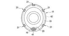
図1から図4に示されるように、内視鏡用フード2は、透光性材料で形成されており、略円筒形状を有するキャップ部11と、体腔内に挿入される内視鏡12の挿入部13の先端部に着脱可能に取り付けられる略円筒形状の取付部14と、キャップ部11の基端部と取付部14とを接続するテーパ状に形成された段差部15と、段差部15に連結された軟性チューブ16とを備えている。 As shown in FIGS. 1 to 4, the
キャップ部11は、取付部14よりも開口径が大きく、先端部がキャップ部11の軸方向に対して斜めに形成されている。
取付部14は、その内径が挿入部13の外径とほぼ同径であり、先端の開口径が挿入部13の先端部の外径よりも小径となるように内周面の内方に突き出したフランジ状の内視鏡係止部17が設けられている。
段差部15には、キャップ部11の内側に連通する連通口18が形成されており、軟性チューブ16の先端部が連結されている。ここで、軟性チューブ16の先端部は、接着、溶着等の手段により、キャップ部11に気密を保った状態で固着されている。
ここで、軟性チューブ16の中心軸16Aとキャップ部11の中心軸11Aとが略平行になるように連結されている。The
The
A
Here, the
キャップ部11の先端部には、内周面の内方に均一の幅で突き出した爪部(フランジ部)19が設けられている。
爪部19は、爪部19の一部を切り欠いて形成された領域であるスネアワイヤ繰り出し部20と、周方向に適宜間隔をあけて形成された弾性係止部21とを有している。
スネアワイヤ繰り出し部20は、軟性チューブ16の先端開口に対向する位置で爪部19を切り欠いて形成されており、軟性チューブ16の中心軸16Aがスネアワイヤ繰り出し部20の範囲内を通過するように形成されている。
弾性係止部21は、爪部19の略中央部で周方向に形成されたスリット22Aと、そのスリット22Aの両端からキャップ部11の外周壁わたり適当な幅で中心軸方向に略平行に形成された2つのスリット22Bとによって形成された係止片23を周方向内側に折り曲げることによって形成されている。A claw portion (flange portion) 19 is provided at the tip portion of the
The
The snare
The
図1に示されるように、軟性チューブ16の基端側は、シースを開放可能に固定すると共に軟性チューブ16を内視鏡12に固定するための固定手段3に接続されている。
固定手段3は、内視鏡12に固定するフック31と、シース固定部32とを備えている。
フック31には、孔部31Aが形成されており、基端側には軟性チューブ16とシース固定部32とに接続する連通口(図示略)を有している。
また、シース固定部32は、軟性チューブ16内に通じる通孔35A及び雄ネジ35Bを有する基部35と、雄ネジ35Bに螺合する雌ネジ36Aを有する回転環36と、雄ネジ35Bに回転環36が螺合することによって基部35及び回転環36に収納され通孔37Aを有する弾性管37とから構成されている。As shown in FIG. 1, the proximal end side of the
The fixing means 3 includes a
The
The sheath fixing portion 32 includes a
軟性チューブ16には高周波スネア部4が挿通されている。
図1から図4に示されるように、高周波スネア部4は、軟性チューブ16に挿入され可撓性を有するシース(スネアシース)32と、シース41の先端側から突出し略円環状を有するスネアワイヤ42と、シース41の基端側にシース41の先端から突出するスネアワイヤ42の長さを制御する操作部43と、シース41内に挿通されスネアワイヤ42と操作部43とを接続する操作ワイヤ(図示略)を有している。The high-frequency snare portion 4 is inserted through the
As shown in FIGS. 1 to 4, the high-frequency snare section 4 includes a flexible sheath (snare sheath) 32 that is inserted into the
シース41は、軟性チューブ16と通孔35Aと弾性管37とに挿通され、弾性管37の通孔37A内に固定されており、回転環36に設けられたノブ36Aを回転させることにより内蔵された弾性管37の通孔37Aが緩み、シース41が進退可能とされている。
スネアワイヤ42は、図2から図4に示されるように、シース41の先端側からキャップ部11のスネアワイヤ繰り出し部20に繰り出て、キャップ部11の爪部19に沿い、爪部19の内側に係留され、爪部19と係止片23とで交互に保持されることで定位置に配置されている。The
2 to 4, the
操作部43は、本体44と、操作ワイヤの片端部が接続され本体44に対して進退自在に設けられたスライダ45と、スライダ45の進退方向の動きを規制する規制部材46とを有している。
本体44には、操作時に操作者の指をかける指かけ孔部44Aが設けられている。また、スライダ45にも、同様の指かけ孔部45Aが設けられている。
規制部材46には、スライダ45の指かけ孔部45Aに嵌合する凸部47と、本体44に固定する固定部48とが設けられ、スライダ45の進退方向の動きが規制されるようになっている。The
The
The restricting
上記の構成からなる内視鏡用粘膜切除具1を用いた粘膜A1の切除方法について図5を参照して説明する。
先ず、図5(a)に示されるように取付部14に内視鏡12の挿入部13の先端部を装着し、軟性チューブ16を内視鏡12の挿入部13に沿って、医療用テープ等で固定する。そして、フック31を内視鏡12の鉗子栓12A近傍に掛けて固定する。
この状態で、内視鏡12及び内視鏡用フード2を体腔内へ挿入し、キャップ部11の先端開口を目的の粘膜切除部分A2に向けて移動させる。そして、キャップ部11の先端開口を粘膜A1に押圧する。この状態で、内視鏡12のチャンネルを経由して、吸引装置(図示略)から吸引することにより、粘膜A1が負圧によりキャップ部11の内部に引き込まれて粘膜A1の切除部分A2が隆起される。
次に、図5(b)に示されるように、高周波スネア部4の操作部43から規制部材46を取り外し、スライダ45を本体44に対して後退させると、スネアワイヤ42は図2に示す弾性係止部21から外れてシース41に引き込まれ、粘膜A1の切除部分A2の根元を緊縛する。A method for excising the mucous membrane A1 using the endoscope
First, as shown in FIG. 5A, the distal end portion of the
In this state, the
Next, as shown in FIG. 5B, when the regulating
次に、図5(c)に示されるように、固定手段3のノブ36Aを保持して回転環36を回転させることで弾性管37の通孔37Aを緩め、シース41の進退を可能にしてシース41を軟性チューブ16内に押し込む。このとき、シース41の先端がキャップ部11から突出するので、スネアワイヤ42で緊縛した切除部分A2がキャップ部11内から突出する。
この後、内視鏡12のチャンネルに挿通した超音波プローブ等を用いて粘膜A1や筋層A3の状態を検査し、筋層A3を巻き込んでいない状態を確認する。
そして、切除部分A2を引き絞りながら、スネアワイヤ42に高周波電流を流して粘膜A1を切除する。切除した粘膜A1は、超音波プローブ等を内視鏡12のチャンネルから抜去した後、チャンネルで吸引し、キャップ部11内に保持した状態で内視鏡12と共に体腔外へ取出されて回収される。Next, as shown in FIG. 5 (c), by holding the
Thereafter, the state of the mucous membrane A1 and the muscle layer A3 is examined using an ultrasonic probe or the like inserted through the channel of the
Then, the mucous membrane A1 is excised by applying a high-frequency current to the
本実施形態の内視鏡用粘膜切除具1では、軟性チューブ16の中心軸16Aが、軟性チューブ16の先端開口に挿通される高周波スネア部4のシース41の中心軸をスネアワイヤ繰り出し部20の範囲内を通過させる位置に配されているため、スネアワイヤ42を爪部19の内側に配した際にスネアワイヤ42のシース41近傍部分が確実に爪部19の内側に係留される。また、爪部19に弾性係止部21が形成されていることによって、スネアワイヤ42を爪部19の内側部分により確実に配置される。したがって、体腔内への挿入時や体腔内でキャップ部11が外力を受けて変形した際にキャップ部11からスネアワイヤ42が外れることを抑制できる。 In the endoscopic
なお、上記第1の実施形態では、内視鏡用粘膜切除具1は予め高周波スネア3のシース41を軟性チューブ16に挿通し、スネアワイヤ42を爪部19内側部分に係留させたが、体腔内に挿入させる前にシース41を軟性チューブ16に挿通してスネアワイヤ42を係留させればよい。このとき、シース41が固定手段3を介して軟性チューブ16に挿通された後、回転環36のノブ36Aを回転させ弾性管37の通孔37Aを収縮させることによりシース41の進退を固定する。 In the first embodiment, the endoscopic
次に、第2の実施形態について図6を参照しながら説明する。
なお、ここで説明する実施形態はその基本的構成が上述した第1の実施形態と同様であり、上述の第1の実施形態に別の要素を付加したものである。したがって、図6においては、図3と同一構成要素に同一符号をし、この説明を省略する。Next, a second embodiment will be described with reference to FIG.
The basic configuration of the embodiment described here is the same as that of the first embodiment described above, and another element is added to the first embodiment described above. Therefore, in FIG. 6, the same components as those in FIG.
第2の実施形態と第1の実施形態との異なる点は、第1の実施形態では爪部19の幅が均一に設けられているのに対して、第2の実施形態における内視鏡用フード60では、キャップ部61がスネアワイヤ繰り出し部62に向かって幅が増大する爪部63を有している点である。すなわち、図6に示されるように、爪部63による開口中心63Aがキャップ部61の中心軸61Aに比べてスネアワイヤ繰り出し部62から遠ざかるように形成されている。 The difference between the second embodiment and the first embodiment is that the width of the
この内視鏡用フード60は、第1の実施形態に係る内視鏡用フード2と同様の作用、効果を有するが、スネアワイヤ繰り出し部62の範囲が大きく形成され、軟性チューブ16の中心が爪部63の内側縁からより外周方向へ離れることで、スネアワイヤ42のシース41近傍部分をより確実に爪部63の内側に係留させることができる。 The
次に、第3の実施形態について図7を参照しながら説明する。
なお、ここで説明する実施形態はその基本的構成が上述した第1の実施形態と同様であり、上述の第1の実施形態に別の要素を付加したものである。したがって、図7においては、図2(a)と同一構成要素に同一符号をし、この説明を省略する。Next, a third embodiment will be described with reference to FIG.
The basic configuration of the embodiment described here is the same as that of the first embodiment described above, and another element is added to the first embodiment described above. Therefore, in FIG. 7, the same components as those in FIG.
第3の実施形態と第1の実施形態との異なる点は、第1の実施形態では軟性チューブ16の中心軸16Aがキャップ部11の中心軸11Aと平行であるのに対して、第3の実施形態における内視鏡用フード70では、図7に示されるように、先端側において軟性チューブ71の中心軸71Aがキャップ部11の中心軸11Aに対して爪部19の半径方向外方に向かって傾斜して配されている点である。 The difference between the third embodiment and the first embodiment is that, in the first embodiment, the
この内視鏡用フード70は、第1の実施形態に係る内視鏡用フード2と同様の作用、効果を有するが、軟性チューブ71の中心軸71Aがキャップ部11の中心軸11Aに対して爪部19の半径方向外方へ離れることで、スネアワイヤ42のシース41近傍部分がより確実に爪部19の内側に係留される。 The
次に、第4の実施形態について図8及び図9を参照しながら説明する。
なお、ここで説明する実施形態はその基本的構成が上述した第1の実施形態と同様であり、上述の第1の実施形態に別の要素を付加したものである。したがって、図8及び図9においては、図2(a)及び図3と同一構成要素に同一符号をし、この説明を省略する。Next, a fourth embodiment will be described with reference to FIGS.
The basic configuration of the embodiment described here is the same as that of the first embodiment described above, and another element is added to the first embodiment described above. Therefore, in FIG. 8 and FIG. 9, the same components as those in FIG. 2A and FIG.
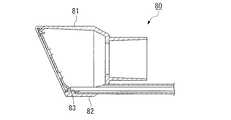
第4の実施形態と第1の実施形態との異なる点は、第1の実施形態ではキャップ部11が略円筒形状であるのに対して、第4の実施形態における内視鏡用フード80では、図8及び図9に示されるように、キャップ部81が外壁から突出し先端に向かって延在する突条部82を有すると共に、内面に突条部82に対応した溝部83が形成され、溝部83に軟性チューブ16の先端側が配されている点である。 The difference between the fourth embodiment and the first embodiment is that the
この内視鏡用フード80は、第1の実施形態に係る内視鏡用フード2と同様の作用、効果を有するが、溝部83に軟性チューブ16の先端が配されているため、軟性チューブ16が半径方向外方に離れることで、スネアワイヤ42のシース41近傍部分がより確実に爪部19の内側に係留される。また、溝部83にシース41が配されることで、シース41の周方向の動きが規制される。 The
なお、本発明には、以下のものが含まれる。
[付記]
(付記項1) 先端縁の内周面の内方に突き出したフランジ部を有する略筒形状のキャップ部と、該キャップ部の基端に設けられ内視鏡の挿入部先端に取り付ける取付部と、先端開口が前記キャップ部の内側に連通すると共に該キャップ部を内視鏡に取り付けた際に内視鏡の挿入部の外に配置されて高周波スネアのスネアシースを挿通させる軟性チューブとを備え、該軟性チューブを通じて前記キャップ部内に挿入した高周波スネアのスネアワイヤを該キャップ部内に広げて前記フランジ部内側に配置可能な内視鏡用フードにおいて、前記フランジ部における前記軟性チューブの先端開口に対向する位置で一部を切り欠いて形成されたスネアワイヤ繰り出し部を備え、前記軟性チューブの中心軸が、前記スネアワイヤ繰り出し部の範囲内を通過する位置に配されていることを特徴とする内視鏡用フード。The present invention includes the following.
[Appendix]
(Additional Item 1) A substantially cylindrical cap portion having a flange portion protruding inward of the inner peripheral surface of the distal end edge, and an attachment portion provided at the proximal end of the cap portion and attached to the distal end of the insertion portion of the endoscope A flexible tube that communicates with the inside of the cap portion and that is disposed outside the insertion portion of the endoscope and allows the snare sheath of the high-frequency snare to be inserted when the cap portion is attached to the endoscope. In the endoscope hood capable of spreading a snare wire of a high-frequency snare inserted into the cap portion through the flexible tube and placing the snare wire inside the cap portion, a position facing the distal end opening of the flexible tube in the flange portion A snare wire feeding portion formed by cutting out a part of the flexible tube, and the central axis of the flexible tube passes through the range of the snare wire feeding portion. Endoscopic hood characterized by being arranged at a position to be
(付記項2) 先端縁の内周面の内方に突き出したフランジ部を有する略筒形状のキャップ部と、該キャップ部の基端に設けられ内視鏡の挿入部先端に取り付ける取付部と、先端開口が前記キャップ部の内側に連通すると共に該キャップ部を内視鏡に取り付けた際に内視鏡の挿入部の外に配置されて高周波スネアのスネアシースを挿通させる軟性チューブとを備え、該軟性チューブを通じて前記キャップ部内に挿入した高周波スネアのスネアワイヤを該キャップ部内に広げて前記フランジ部内側に配置可能な内視鏡用フードにおいて、前記フランジ部における前記軟性チューブの先端開口に対向する位置で一部を切り欠いて形成されたスネアワイヤ繰り出し部を備え、該軟性チューブの先端開口に挿通される前記スネアシースの中心軸が、前記スネアワイヤ繰り出し部の範囲内を通過する位置に配されていることを特徴とする内視鏡用フード。 (Additional Item 2) A substantially cylindrical cap portion having a flange portion protruding inward of the inner peripheral surface of the distal end edge, and an attachment portion provided at the proximal end of the cap portion and attached to the distal end of the insertion portion of the endoscope A flexible tube that communicates with the inside of the cap portion and that is disposed outside the insertion portion of the endoscope and allows the snare sheath of the high-frequency snare to be inserted when the cap portion is attached to the endoscope. In the endoscope hood capable of spreading a snare wire of a high-frequency snare inserted into the cap portion through the flexible tube and placing the snare wire inside the cap portion, a position facing the distal end opening of the flexible tube in the flange portion A snare wire feed portion formed by cutting out a part of the snare sheath, and the central axis of the snare sheath inserted through the distal end opening of the flexible tube is Food endoscopic, characterized by being arranged at a position passing through the range of the snare wire feeding unit.
(付記項3) 前記フランジ部の幅が、前記スネア繰り出し部に向かって増大するように形成されていることを特徴とする付記項1又は付記項2に記載の内視鏡用フード。 (Additional Item 3) The endoscope hood according to
この発明によれば、フランジ部の幅がスネア繰り出し部に向かって増大するように形成されているので、スネアワイヤ繰り出し部を大きく形成し、より確実にスネアシース近傍のスネアワイヤをフランジ部の内側に係留することができる。 According to this invention, since the width of the flange portion is formed so as to increase toward the snare payout portion, the snare wire payout portion is formed large, and the snare wire near the snare sheath is more securely moored inside the flange portion. be able to.
(付記項4) 前記軟性チューブの少なくとも先端側の中心軸が、前記キャップ部の中心軸に対して前記フランジ部の半径方向外方に向かって傾斜していることを特徴とする付記項1又は付記項2のいずれかに記載の内視鏡用フード。 (Additional Item 4)
この発明によれば、キャップ部の中心軸に対してフランジ部の半径方向外方に向かって傾斜しているので、スネアシースから繰り出されるスネアワイヤがフランジ部のより半径方向外側のフランジ部の外周縁側に配されてより確実に係留させることができる。 According to the present invention, since the flange portion is inclined outward in the radial direction with respect to the central axis of the cap portion, the snare wire fed out from the snare sheath is located on the outer peripheral edge side of the flange portion on the radially outer side of the flange portion. It can be arranged and moored more reliably.
(付記項5) 前記キャップ部が外壁から突出し先端に向かって延在する突条部を有すると共に内面に該突条部に対応した溝部が形成され、該溝部に前記軟性チューブの先端側が配されていることを特徴とする付記項1又は付記項2に記載の内視鏡用フード。 (Additional Item 5) The cap portion has a protrusion that protrudes from the outer wall and extends toward the tip, and a groove corresponding to the protrusion is formed on the inner surface, and the tip of the flexible tube is disposed in the groove. The endoscope hood as set forth in
この発明によれば、突条部に対応した溝部内に軟性チューブの先端側が配されているので、より半径方向外側に軟性チューブを配置させることができるので、軟性チューブにあるスネアシースから繰り出されるスネアワイヤをフランジ部のより半径方向外側に配することができる。 According to the present invention, since the distal end side of the flexible tube is arranged in the groove corresponding to the protruding portion, the flexible tube can be arranged on the outer side in the radial direction, so that the snare wire fed out from the snare sheath in the flexible tube Can be arranged on the radially outer side of the flange portion.
(付記項6) 前記キャップ部の先端縁近傍の少なくとも一部に、前記フランジ部及びキャップ部の先端縁近傍に設けられたスリットによって前記キャップ部と一体的に形成され、前記フランジ部と共にスネアワイヤを保持する弾性係止部が前記キャップ部の内側に設けられていることを特徴とする付記項1又は付記項2に記載の内視鏡用フード。 (Additional Item 6) At least a part near the tip edge of the cap part is integrally formed with the cap part by a slit provided near the tip edge of the flange part and the cap part, and a snare wire is formed together with the flange part. The endoscope hood according to
この発明によれば、スネアワイヤをフランジ部と弾性係止部とで保持することによってより確実に保持され、外れることを抑制する。 According to the present invention, the snare wire is held more securely by holding the flange portion and the elastic locking portion, and is prevented from coming off.
(付記項7) 付記項1から付記項6のいずれかに記載の内視鏡用フードと、スネアシース内にスネアワイヤが挿通される高周波スネアとを備えることを特徴とする内視鏡用粘膜切除具。 (Additional Item 7) An endoscopic mucosal resection tool comprising the endoscope hood according to any one of
なお、本発明は、上記実施形態に限定されるものではなく、本発明の趣旨を逸脱しない範囲において種々の変更を加えることが可能である。
例えば、上記各実施形態では、キャップ部の先端がキャップ部の中心軸に対して斜めに形成されていたが、中心軸に対して垂直な面で形成されてもよい。In addition, this invention is not limited to the said embodiment, A various change can be added in the range which does not deviate from the meaning of this invention.
For example, in each of the above embodiments, the tip of the cap portion is formed obliquely with respect to the central axis of the cap portion, but may be formed with a surface perpendicular to the central axis.
1 内視鏡用粘膜切除具
2、60、70、80 内視鏡用フード
4 高周波スネア
11、61、81 キャップ部
12 内視鏡
13 挿入部
14 取付部
16、71 軟性チューブ
16A、71A 軟性チューブの中心軸
19、63 爪部(フランジ部)
20、62 スネアワイヤ繰り出し部
41 シース(スネアシース)
42 スネアワイヤDESCRIPTION OF
20, 62 Snare
42 Snare Wire
Claims (3)
Translated fromJapanese該軟性チューブを通じて前記キャップ部内に挿入した高周波スネアのスネアワイヤを該キャップ部内に広げて前記フランジ部内側に配置可能な内視鏡用フードにおいて、
前記フランジ部における前記軟性チューブの先端開口に対向する位置で一部を切り欠いて形成されたスネアワイヤ繰り出し部を備え、前記軟性チューブの中心軸が、前記スネアワイヤ繰り出し部の範囲内を通過する位置に配されていることを特徴とする内視鏡用フード。A substantially cylindrical cap portion having a flange portion projecting inwardly on the inner peripheral surface of the distal end edge, a mounting portion provided at the proximal end of the cap portion and attached to the distal end of the insertion portion of the endoscope, A flexible tube that communicates with the inside of the cap portion and is disposed outside the insertion portion of the endoscope when the cap portion is attached to the endoscope and allows the high-frequency snare sheath to pass therethrough,
In an endoscope hood capable of spreading a snare wire of a high-frequency snare inserted into the cap part through the flexible tube and placing the snare wire inside the cap part,
A snare wire feeding portion formed by cutting out a part of the flange portion at a position facing the distal end opening of the flexible tube, and a center axis of the flexible tube passing through a range of the snare wire feeding portion; Endoscopic hood characterized by being arranged.
該軟性チューブを通じて前記キャップ部内に挿入した高周波スネアのスネアワイヤを該キャップ部内に広げて前記フランジ部内側に配置可能な内視鏡用フードにおいて、
前記フランジ部における前記軟性チューブの先端開口に対向する位置で一部を切り欠いて形成されたスネアワイヤ繰り出し部を備え、該軟性チューブの先端開口に挿通される前記スネアシースの中心軸が、前記スネアワイヤ繰り出し部の範囲内を通過する位置に配されていることを特徴とする内視鏡用フード。A substantially cylindrical cap portion having a flange portion projecting inwardly on the inner peripheral surface of the distal end edge, a mounting portion provided at the proximal end of the cap portion and attached to the distal end of the insertion portion of the endoscope, A flexible tube that communicates with the inside of the cap portion and is disposed outside the insertion portion of the endoscope when the cap portion is attached to the endoscope and allows the high-frequency snare sheath to pass therethrough,
In an endoscope hood capable of spreading a snare wire of a high-frequency snare inserted into the cap part through the flexible tube and placing the snare wire inside the cap part,
A snare wire feeding portion formed by cutting out a part of the flange portion at a position facing the distal end opening of the flexible tube, and a central axis of the snare sheath inserted through the distal end opening of the flexible tube is configured to Endoscope hood, wherein the hood is arranged at a position passing through the range of the section.
Priority Applications (3)
| Application Number | Priority Date | Filing Date | Title |
|---|---|---|---|
| JP2003290284AJP4266743B2 (en) | 2003-08-08 | 2003-08-08 | Endoscopic hood and endoscopic mucosal resection tool |
| US10/910,671US7122002B2 (en) | 2003-08-08 | 2004-08-03 | Endoscope hood and endoscopic mucosa cutting device |
| DE102004037830.4ADE102004037830B4 (en) | 2003-08-08 | 2004-08-04 | Endoscope cap and endoscopic mucosal cutting device |
Applications Claiming Priority (1)
| Application Number | Priority Date | Filing Date | Title |
|---|---|---|---|
| JP2003290284AJP4266743B2 (en) | 2003-08-08 | 2003-08-08 | Endoscopic hood and endoscopic mucosal resection tool |
Publications (2)
| Publication Number | Publication Date |
|---|---|
| JP2005058343A JP2005058343A (en) | 2005-03-10 |
| JP4266743B2true JP4266743B2 (en) | 2009-05-20 |
Family
ID=34114122
Family Applications (1)
| Application Number | Title | Priority Date | Filing Date |
|---|---|---|---|
| JP2003290284AExpired - Fee RelatedJP4266743B2 (en) | 2003-08-08 | 2003-08-08 | Endoscopic hood and endoscopic mucosal resection tool |
Country Status (3)
| Country | Link |
|---|---|
| US (1) | US7122002B2 (en) |
| JP (1) | JP4266743B2 (en) |
| DE (1) | DE102004037830B4 (en) |
Families Citing this family (50)
| Publication number | Priority date | Publication date | Assignee | Title |
|---|---|---|---|---|
| US8137364B2 (en) | 2003-09-11 | 2012-03-20 | Abbott Laboratories | Articulating suturing device and method |
| US6964668B2 (en) | 1999-03-04 | 2005-11-15 | Abbott Laboratories | Articulating suturing device and method |
| US6391048B1 (en) | 2000-01-05 | 2002-05-21 | Integrated Vascular Systems, Inc. | Integrated vascular device with puncture site closure component and sealant and methods of use |
| US7842068B2 (en) | 2000-12-07 | 2010-11-30 | Integrated Vascular Systems, Inc. | Apparatus and methods for providing tactile feedback while delivering a closure device |
| US6461364B1 (en) | 2000-01-05 | 2002-10-08 | Integrated Vascular Systems, Inc. | Vascular sheath with bioabsorbable puncture site closure apparatus and methods of use |
| DE60144328D1 (en) | 2000-09-08 | 2011-05-12 | Abbott Vascular Inc | Surgical clamp |
| US6626918B1 (en) | 2000-10-06 | 2003-09-30 | Medical Technology Group | Apparatus and methods for positioning a vascular sheath |
| US6695867B2 (en) | 2002-02-21 | 2004-02-24 | Integrated Vascular Systems, Inc. | Plunger apparatus and methods for delivering a closure device |
| US6623510B2 (en) | 2000-12-07 | 2003-09-23 | Integrated Vascular Systems, Inc. | Closure device and methods for making and using them |
| US8690910B2 (en) | 2000-12-07 | 2014-04-08 | Integrated Vascular Systems, Inc. | Closure device and methods for making and using them |
| US8905937B2 (en) | 2009-02-26 | 2014-12-09 | Integrated Vascular Systems, Inc. | Methods and apparatus for locating a surface of a body lumen |
| US8398656B2 (en) | 2003-01-30 | 2013-03-19 | Integrated Vascular Systems, Inc. | Clip applier and methods of use |
| US7462188B2 (en) | 2003-09-26 | 2008-12-09 | Abbott Laboratories | Device and method for suturing intracardiac defects |
| US7225024B2 (en)* | 2003-09-30 | 2007-05-29 | Cardiac Pacemakers, Inc. | Sensors having protective eluting coating and method therefor |
| JP4441227B2 (en)* | 2003-10-08 | 2010-03-31 | Hoya株式会社 | Endoscope for high frequency treatment |
| IES20040368A2 (en) | 2004-05-25 | 2005-11-30 | James E Coleman | Surgical stapler |
| US8926633B2 (en) | 2005-06-24 | 2015-01-06 | Abbott Laboratories | Apparatus and method for delivering a closure element |
| US8313497B2 (en) | 2005-07-01 | 2012-11-20 | Abbott Laboratories | Clip applier and methods of use |
| US8083754B2 (en) | 2005-08-08 | 2011-12-27 | Abbott Laboratories | Vascular suturing device with needle capture |
| US8758397B2 (en) | 2005-08-24 | 2014-06-24 | Abbott Vascular Inc. | Vascular closure methods and apparatuses |
| US8920442B2 (en) | 2005-08-24 | 2014-12-30 | Abbott Vascular Inc. | Vascular opening edge eversion methods and apparatuses |
| US20070060895A1 (en) | 2005-08-24 | 2007-03-15 | Sibbitt Wilmer L Jr | Vascular closure methods and apparatuses |
| US9456811B2 (en)* | 2005-08-24 | 2016-10-04 | Abbott Vascular Inc. | Vascular closure methods and apparatuses |
| US8808310B2 (en) | 2006-04-20 | 2014-08-19 | Integrated Vascular Systems, Inc. | Resettable clip applier and reset tools |
| WO2007131112A2 (en) | 2006-05-03 | 2007-11-15 | Indiana University Research & Technology Corporation | Methods and apparatuses for reshaping the esophagus and other body lumens |
| JP4875445B2 (en) | 2006-09-22 | 2012-02-15 | オリンパスメディカルシステムズ株式会社 | Endoscopic treatment tool |
| US8574244B2 (en) | 2007-06-25 | 2013-11-05 | Abbott Laboratories | System for closing a puncture in a vessel wall |
| US8893947B2 (en) | 2007-12-17 | 2014-11-25 | Abbott Laboratories | Clip applier and methods of use |
| JP2010022697A (en)* | 2008-07-23 | 2010-02-04 | Olympus Medical Systems Corp | cap |
| US8863748B2 (en)* | 2008-07-31 | 2014-10-21 | Olympus Medical Systems Corp. | Endoscopic surgical operation method |
| US9486191B2 (en) | 2009-01-09 | 2016-11-08 | Abbott Vascular, Inc. | Closure devices |
| DE102009050829B4 (en) | 2009-10-27 | 2013-01-24 | Ovesco Endoscopy Ag | resection |
| EP2603131A1 (en)* | 2010-08-10 | 2013-06-19 | Cook Medical Technologies LLC | Endoscopic system for resection of tissue |
| US9370353B2 (en) | 2010-09-01 | 2016-06-21 | Abbott Cardiovascular Systems, Inc. | Suturing devices and methods |
| US9149276B2 (en) | 2011-03-21 | 2015-10-06 | Abbott Cardiovascular Systems, Inc. | Clip and deployment apparatus for tissue closure |
| US9414822B2 (en) | 2011-05-19 | 2016-08-16 | Abbott Cardiovascular Systems, Inc. | Tissue eversion apparatus and tissue closure device and methods for use thereof |
| US8858573B2 (en) | 2012-04-10 | 2014-10-14 | Abbott Cardiovascular Systems, Inc. | Apparatus and method for suturing body lumens |
| US9241707B2 (en) | 2012-05-31 | 2016-01-26 | Abbott Cardiovascular Systems, Inc. | Systems, methods, and devices for closing holes in body lumens |
| US9364209B2 (en) | 2012-12-21 | 2016-06-14 | Abbott Cardiovascular Systems, Inc. | Articulating suturing device |
| WO2014151938A2 (en)* | 2013-03-14 | 2014-09-25 | Boston Scientific Scimed, Inc. | Tissue resection device and related methods of use |
| US20140276810A1 (en)* | 2013-03-14 | 2014-09-18 | Boston Scientific Scimed, Inc. | Devices for tissue resection |
| DE102013224961B4 (en)* | 2013-12-05 | 2021-12-23 | Richard Wolf Gmbh | Endoscope with two-part suction attachment |
| CN104546119A (en)* | 2015-01-05 | 2015-04-29 | 张建国 | Mucous membrane detacher |
| US10251666B2 (en)* | 2015-05-20 | 2019-04-09 | Boston Scientific Scimed, Inc. | Endoscopic mucosal resection single step hood |
| WO2017018003A1 (en)* | 2015-07-24 | 2017-02-02 | オリンパス株式会社 | Medical instrument |
| WO2017018218A1 (en)* | 2015-07-24 | 2017-02-02 | オリンパス株式会社 | Medical instrument |
| EP3344111B1 (en)* | 2015-09-03 | 2019-07-03 | Richard Wolf GmbH | Shaft instrument and in particular a medical endoscopic shaft instrument |
| EP3442396B1 (en) | 2016-07-01 | 2020-03-11 | Boston Scientific Scimed Inc. | Device for engaging of medical tools |
| US20230165581A1 (en)* | 2020-04-27 | 2023-06-01 | Ping Wang | Suture device, treatment device with suture device, and treatment system |
| EP3970641B1 (en)* | 2020-09-17 | 2025-04-23 | Gyrus ACMI, Inc. d/b/a Olympus Surgical Technologies America | Endoscopic tip extender |
Family Cites Families (16)
| Publication number | Priority date | Publication date | Assignee | Title |
|---|---|---|---|---|
| US4550715A (en)* | 1983-10-24 | 1985-11-05 | Codman & Shurtleff, Inc. | Endoscope insertion cannula assembly |
| US4610242A (en)* | 1984-04-18 | 1986-09-09 | Codman & Shurtleff, Inc. | Endoscope insertion cannula assembly |
| US5267977A (en)* | 1992-10-29 | 1993-12-07 | Feeney Jr Richard J | No-stick syringe |
| JP2585912Y2 (en) | 1993-04-15 | 1998-11-25 | オリンパス光学工業株式会社 | Hood for endoscope |
| US6059719A (en)* | 1997-08-06 | 2000-05-09 | Olympus Optical Co., Ltd. | Endoscope system |
| JPH11299725A (en)* | 1998-04-21 | 1999-11-02 | Olympus Optical Co Ltd | Hood for endoscope |
| JP2001275933A (en) | 2000-03-31 | 2001-10-09 | Olympus Optical Co Ltd | Hood for endoscope |
| JP4674975B2 (en)* | 2000-05-26 | 2011-04-20 | オリンパス株式会社 | Endoscope hood |
| US6761684B1 (en)* | 2000-08-10 | 2004-07-13 | Linvatec Corporation | Endoscope tip protection system |
| JP3533163B2 (en)* | 2000-09-18 | 2004-05-31 | ペンタックス株式会社 | Endoscope tip |
| US6695774B2 (en)* | 2001-01-19 | 2004-02-24 | Endactive, Inc. | Apparatus and method for controlling endoscopic instruments |
| WO2002062262A2 (en)* | 2001-02-02 | 2002-08-15 | Insight Instruments, Inc. | Endoscope system and method of use |
| JP3826045B2 (en)* | 2002-02-07 | 2006-09-27 | オリンパス株式会社 | Endoscope hood |
| EP1386633A1 (en)* | 2002-08-02 | 2004-02-04 | Sergio Restelli | Safety catheter |
| JP4391765B2 (en) | 2002-12-02 | 2009-12-24 | オリンパス株式会社 | Endoscopic mucosal resection tool |
| JP4094445B2 (en) | 2003-01-31 | 2008-06-04 | オリンパス株式会社 | Endoscopic mucosal resection tool |
- 2003
- 2003-08-08JPJP2003290284Apatent/JP4266743B2/ennot_activeExpired - Fee Related
- 2004
- 2004-08-03USUS10/910,671patent/US7122002B2/ennot_activeExpired - Lifetime
- 2004-08-04DEDE102004037830.4Apatent/DE102004037830B4/ennot_activeExpired - Fee Related
Also Published As
| Publication number | Publication date |
|---|---|
| DE102004037830A1 (en) | 2005-03-10 |
| US7122002B2 (en) | 2006-10-17 |
| JP2005058343A (en) | 2005-03-10 |
| US20050033115A1 (en) | 2005-02-10 |
| DE102004037830B4 (en) | 2019-01-17 |
Similar Documents
| Publication | Publication Date | Title |
|---|---|---|
| JP4266743B2 (en) | Endoscopic hood and endoscopic mucosal resection tool | |
| EP1902668B1 (en) | Endoscopic treatment instrument | |
| JP7144871B2 (en) | Tissue clip application attachment set/retrofit set | |
| JP4094445B2 (en) | Endoscopic mucosal resection tool | |
| US4643187A (en) | High-frequency incising and excising instrument | |
| JP3902290B2 (en) | Endoscope ligature | |
| JP4197965B2 (en) | High frequency snare and medical equipment | |
| EP2322109B1 (en) | Treatment instrument for endoscope | |
| US7922717B2 (en) | High-frequency treatment tool for endoscope | |
| US7588580B2 (en) | Mucosa excision device using endoscope | |
| EP2000105A2 (en) | Endoscopic treatment tool | |
| US11771455B2 (en) | Endoscopic resection assembly | |
| WO2006112231A1 (en) | Attachment for endoscope, treatment instrument for endoscope, and endoscope system | |
| JP3845173B2 (en) | Endoscope for ligation treatment | |
| JP2010042084A (en) | Treatment instrument for endoscope | |
| JP4349870B2 (en) | Endoscope tip hood | |
| JP4701833B2 (en) | High frequency treatment tool | |
| JP2009142416A (en) | Endoscopic high-frequency treatment instrument | |
| JP2006325812A (en) | High frequency treating implement | |
| JP4579011B2 (en) | Gastric fistula catheter introduction device for gastric fistula catheter exchange |
Legal Events
| Date | Code | Title | Description |
|---|---|---|---|
| A621 | Written request for application examination | Free format text:JAPANESE INTERMEDIATE CODE: A621 Effective date:20060629 | |
| A131 | Notification of reasons for refusal | Free format text:JAPANESE INTERMEDIATE CODE: A131 Effective date:20080812 | |
| TRDD | Decision of grant or rejection written | ||
| A01 | Written decision to grant a patent or to grant a registration (utility model) | Free format text:JAPANESE INTERMEDIATE CODE: A01 Effective date:20090127 | |
| A01 | Written decision to grant a patent or to grant a registration (utility model) | Free format text:JAPANESE INTERMEDIATE CODE: A01 | |
| A61 | First payment of annual fees (during grant procedure) | Free format text:JAPANESE INTERMEDIATE CODE: A61 Effective date:20090217 | |
| R151 | Written notification of patent or utility model registration | Ref document number:4266743 Country of ref document:JP Free format text:JAPANESE INTERMEDIATE CODE: R151 | |
| FPAY | Renewal fee payment (event date is renewal date of database) | Free format text:PAYMENT UNTIL: 20120227 Year of fee payment:3 | |
| FPAY | Renewal fee payment (event date is renewal date of database) | Free format text:PAYMENT UNTIL: 20120227 Year of fee payment:3 | |
| FPAY | Renewal fee payment (event date is renewal date of database) | Free format text:PAYMENT UNTIL: 20130227 Year of fee payment:4 | |
| FPAY | Renewal fee payment (event date is renewal date of database) | Free format text:PAYMENT UNTIL: 20140227 Year of fee payment:5 | |
| S531 | Written request for registration of change of domicile | Free format text:JAPANESE INTERMEDIATE CODE: R313531 | |
| R350 | Written notification of registration of transfer | Free format text:JAPANESE INTERMEDIATE CODE: R350 | |
| R250 | Receipt of annual fees | Free format text:JAPANESE INTERMEDIATE CODE: R250 | |
| LAPS | Cancellation because of no payment of annual fees |