JP4266738B2 - Ligation device - Google Patents
Ligation deviceDownload PDFInfo
- Publication number
- JP4266738B2 JP4266738B2JP2003270527AJP2003270527AJP4266738B2JP 4266738 B2JP4266738 B2JP 4266738B2JP 2003270527 AJP2003270527 AJP 2003270527AJP 2003270527 AJP2003270527 AJP 2003270527AJP 4266738 B2JP4266738 B2JP 4266738B2
- Authority
- JP
- Japan
- Prior art keywords
- shaft member
- ligation
- forceps
- operation shaft
- pair
- Prior art date
- Legal status (The legal status is an assumption and is not a legal conclusion. Google has not performed a legal analysis and makes no representation as to the accuracy of the status listed.)
- Expired - Fee Related
Links
Images


Classifications
- A—HUMAN NECESSITIES
- A61—MEDICAL OR VETERINARY SCIENCE; HYGIENE
- A61B—DIAGNOSIS; SURGERY; IDENTIFICATION
- A61B17/00—Surgical instruments, devices or methods
- A61B17/12—Surgical instruments, devices or methods for ligaturing or otherwise compressing tubular parts of the body, e.g. blood vessels or umbilical cord
- A61B17/128—Surgical instruments, devices or methods for ligaturing or otherwise compressing tubular parts of the body, e.g. blood vessels or umbilical cord for applying or removing clamps or clips
- A61B17/1285—Surgical instruments, devices or methods for ligaturing or otherwise compressing tubular parts of the body, e.g. blood vessels or umbilical cord for applying or removing clamps or clips for minimally invasive surgery
- A—HUMAN NECESSITIES
- A61—MEDICAL OR VETERINARY SCIENCE; HYGIENE
- A61B—DIAGNOSIS; SURGERY; IDENTIFICATION
- A61B17/00—Surgical instruments, devices or methods
- A61B17/064—Surgical staples, i.e. penetrating the tissue
- A61B17/0643—Surgical staples, i.e. penetrating the tissue with separate closing member, e.g. for interlocking with staple
- A—HUMAN NECESSITIES
- A61—MEDICAL OR VETERINARY SCIENCE; HYGIENE
- A61B—DIAGNOSIS; SURGERY; IDENTIFICATION
- A61B17/00—Surgical instruments, devices or methods
- A61B17/28—Surgical forceps
- A61B17/2812—Surgical forceps with a single pivotal connection
- A61B17/282—Jaws
- A—HUMAN NECESSITIES
- A61—MEDICAL OR VETERINARY SCIENCE; HYGIENE
- A61B—DIAGNOSIS; SURGERY; IDENTIFICATION
- A61B17/00—Surgical instruments, devices or methods
- A61B17/28—Surgical forceps
- A61B17/29—Forceps for use in minimally invasive surgery
- A61B2017/2926—Details of heads or jaws
Landscapes
- Health & Medical Sciences (AREA)
- Surgery (AREA)
- Life Sciences & Earth Sciences (AREA)
- Heart & Thoracic Surgery (AREA)
- Nuclear Medicine, Radiotherapy & Molecular Imaging (AREA)
- Vascular Medicine (AREA)
- Engineering & Computer Science (AREA)
- Biomedical Technology (AREA)
- Reproductive Health (AREA)
- Medical Informatics (AREA)
- Molecular Biology (AREA)
- Animal Behavior & Ethology (AREA)
- General Health & Medical Sciences (AREA)
- Public Health (AREA)
- Veterinary Medicine (AREA)
- Surgical Instruments (AREA)
Description
Translated fromJapanese本発明は、体腔内に挿入して患部の結紮を行う結紮装置に関する。 The present invention relates to a ligation apparatus that is inserted into a body cavity and ligates an affected area.
従来、金属又は樹脂製のクリップ(結紮部)を塑性変形させることにより血管等の生体組織の患部を結紮する結紮装置が内視鏡下処置に使用されている。このような結紮装置として、先端にクリップを保持した状態で内視鏡の処置具チャンネルに挿入して使用するものが提案されている(例えば、特許文献1、2参照。)。
しかしながら、上記従来の結紮装置においては、表面が滑りやすい患部を結紮する場合、クリップを患部に押し付けて把持しようとしてもクリップ内で患部が滑ってしまう場合や、把持しても固定時に所望の位置からずれてしまう場合があった。
また、クリップを塑性変形させて患部を結紮するので、所望の位置からずれた位置でも一旦操作してしまうとやり直しが困難であった。
本発明は上記事情に鑑みて成されたものであり、結紮処置の際に所望の位置を確実に把持した状態で結紮できる結紮装置を提供することを目的とする。However, in the above-described conventional ligation apparatus, when ligating an affected area where the surface is slippery, even if the clip is pressed against the affected area to be gripped, the affected area will slide within the clip, or the desired position when fixed even when gripped. There was a case where it deviated from.
Moreover, since the affected part is ligated by plastically deforming the clip, it is difficult to redo it once it is operated even at a position shifted from a desired position.
The present invention has been made in view of the above circumstances, and an object thereof is to provide a ligation apparatus capable of ligating in a state where a desired position is securely grasped during ligation treatment.
本発明は、上記課題を解決するため、以下の手段を採用する。
本発明の結紮装置は、一方向に延びる挿入管と、該挿入管の先端側に互いに対向して開閉自在に設けられ生体組織を把持する鉗子部と、前記挿入管の内部に挿通された第1の操作軸部材を介して前記鉗子部と接続され、前記第1の操作軸部材の進退操作によって前記鉗子部を開閉操作する第1の操作機構と、前記挿入管の先端側に前記鉗子部と同軸に設けられ、開拡習性を有して互いに対向した一対の腕部材を閉じて生体組織を結紮する結紮部と、前記挿入管の内部に挿通された第2の操作軸部材を介して前記結紮部に接続され、前記第2の操作軸部材の進退操作によって前記一対の腕部材を閉じるとともに前記結紮部を離脱可能な第2の操作機構とを備え、前記鉗子部は、前記結紮部が前記生体組織を結紮する前の状態において、前記結紮部の腕部材と干渉せずに前記生体組織を把持可能であることを特徴とする。
The present invention employs the following means in order to solve the above problems.
The ligating apparatus of the present invention includes an insertion tube extending in one direction, a forceps portion that is provided on the distal end side of the insertion tube so as to be openable and closable, and that grips a living tissue, and is inserted into the insertion tube. is connected to the gripper via a first operating shaft member, and a first operating mechanism for opening and closing the gripper by advancing and retracting operation of the first operating shaft member,the gripper on the tip side of the insertion tubeVia a ligation part that closes a pair of arm members facing each otherand has a spreadability and ligates a living tissue, and a second operation shaft member that is inserted into the insertion tube A second operating mechanism that is connected to the ligation part and closes the pair of arm members by an advance / retreat operation of the second operation shaft member and is capable of detaching the ligation part, wherein the forceps part includes theligation part in a state before but ligating the body tissue, the ligature Characterized in that without the arm member interference can be gripping the biological tissue.
この結紮装置は、上記の構成を有するので、鉗子部と結紮部とを第1の操作機構と第2の操作機構とによって各別に操作させることができる。したがって、第1の操作機構を操作して第1の操作軸部材を介して鉗子部にて結紮すべき生体組織を把持して結紮場所を確定するとともに、第2の操作機構を操作して第2の操作軸部材を介して結紮部の腕部材を閉じて結紮を行うことができる。
また、第1の操作軸部材により鉗子部を操作して把持のやり直しが可能なので、正確な位置を把持した状態で結紮部を所望の位置に取り付けることができる。Since this ligation apparatus has the above-described configuration, the forceps portion and the ligation portion can be operated separately by the first operation mechanism and the second operation mechanism. Accordingly, the living tissue to be ligated is grasped by the forceps portion through the first operation shaft member by operating the first operation mechanism, and the ligation location is determined, and the second operation mechanism is operated to operate the first operation mechanism. The ligation can be performed by closing the arm member of the ligation part via the two operation shaft members.
In addition, since the forceps can be operated again by operating the first operating shaft member, the ligation part can be attached to a desired position while holding the accurate position.
本発明は、前記結紮装置であって、前記挿入管内に挿通された操作管を備え、前記第2の操作軸部材が前記操作管の内部に進退自在に挿通されていることが好ましい。
この結紮装置は、上記の構成を備えているので、第2の操作軸部材が操作管によって第1の操作軸部材と分離されることにより、第1の操作軸部材と第2の操作軸部材とを互いの干渉を避けて操作することができる。The present invention is preferably the ligation apparatus, further comprising an operation tube inserted into the insertion tube, wherein the second operation shaft member is inserted into the operation tube so as to freely advance and retract.
Since the ligating apparatus has the above-described configuration, the first operation shaft member and the second operation shaft member are separated by separating the second operation shaft member from the first operation shaft member by the operation tube. Can be operated while avoiding mutual interference.
本発明は、前記結紮装置であって、前記鉗子部が開閉可能な一対の鉗子片を備え、該各鉗子片には先端を二股に分けるスリットが形成され、前記結紮部が、前記スリット内で開閉可能とされることが好ましい。
この結紮装置は、上記の構成を有するので、結紮部の開閉操作がスリット内で行われて鉗子部の開閉操作と互いに干渉することなく行うことができる。また、鉗子部で所望の生体組織を把持した中央を結紮部によって結紮処置することができ、より正確な結紮処置が可能となる。The present invention is the ligation apparatus, comprising a pair of forceps pieces capable of opening and closing the forceps portion, each of the forceps pieces is formed with a slit that divides the tip into two portions, and the ligation portion is formed in the slit. It is preferable that it can be opened and closed.
Since this ligation apparatus has the above-described configuration, the ligation part can be opened and closed within the slit without interfering with the forceps part opening and closing operation. In addition, the center where the desired biological tissue is grasped by the forceps portion can be ligated by the ligation portion, and a more accurate ligation treatment can be performed.
本発明は、前記結紮装置であって、前記挿入管、前記第1の操作軸部材及び前記第2の操作軸部材が柔軟性を備えていることが好ましい。
この結紮装置は、上記の構成を備えているので、軟性内視鏡の処置具チャンネルに挿入して使用することができ、軟性内視鏡下の結紮処置を確実に行うことができる。This invention is the said ligation apparatus, Comprising: It is preferable that the said insertion pipe, the said 1st operation shaft member, and the said 2nd operation shaft member are provided with the softness | flexibility.
Since this ligation apparatus has the above-described configuration, it can be used by being inserted into the treatment instrument channel of the flexible endoscope, and the ligation treatment under the flexible endoscope can be reliably performed.
本発明の結紮装置によれば、結紮部で結紮する前に、結紮する場所を鉗子部によって何度でもつかみ直して確定することができ、結紮処置の際に所望の位置を確実に把持した状態で結紮できる。 According to the ligation apparatus of the present invention, before ligating at the ligation part, the place to be ligated can be re-determined by the forceps part, and the desired position can be reliably grasped during the ligation treatment. Can be ligated.
本発明の一実施形態について、図1から図9を参照して説明する。
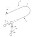
本実施形態に係る結紮装置1は、図1及び図2に示すように、軟性内視鏡Aの処置具チャンネルB内に挿入して使用するもので、結紮装置本体2と、この結紮装置本体2に着脱自在に装着され互いに対向した一対の腕部材3、5を閉じて患部6を結紮するカセット式のクリップユニット(結紮部)7とから構成されている。
結紮装置本体2は、一方向に延びる挿入管8と、挿入管8の先端側に互いに対向して開閉自在に設けられ患部6を把持する鉗子部10と、挿入管8の内部に挿通された第1の操作軸部材11を介して鉗子部10と接続され、第1の操作軸部材11の進退操作によって鉗子部10を開閉操作する第1の操作機構12とを備えている。An embodiment of the present invention will be described with reference to FIGS.
A
The ligating apparatus
また、結紮装置本体2は、図3に示すように、挿入管8の内部に挿通された第2の操作軸部材13を介してクリップユニット7に接続され、第2の操作軸部材13の進退操作によって一対の腕部材3、5を閉じるとともにクリップユニット7を離脱可能な第2の操作機構15とを備えている。
さらに、結紮装置本体2は、挿入管8内に挿通された操作管16を備え、第2の操作軸部材13は操作管16の内部に進退自在に挿通されている。Further, as shown in FIG. 3, the ligating apparatus
Furthermore, the ligation apparatus
挿入管8は、例えば、鋼線からなる密巻きコイルを備えて可撓性とともに柔軟性を有する挿入管本体17と、その外表面を覆う被覆部材18とを備えている。
鉗子部10は、図4に示すように、挿入管8の先端に接続される管状の先端カバー20と、先端カバー20の先端に配設されて互いに対向して開閉可能な一対の鉗子片21、22と、第1の操作軸部材11の進退操作を一対の鉗子片21、22の開閉操作に変換するリンク機構部23とを備えている。
一対の鉗子片21、22は、それぞれ基端から先端に延びる二股の略棒状金属片で形成されており先端側にスリット25が形成されている。また、一対の鉗子片21、22は凹凸状の対向面21a、22aを有しており、この対向面21a、22aによって患部6を把持する。The
As shown in FIG. 4, the
The pair of
第1の操作機構12は、図1及び図2に示すように、第1の操作軸部材11の基端と接続される第1のスライダ26を備えている。この第1のスライダ26の進退操作が第1の操作軸部材11の軸方向の進退動作となって伝達され、この操作軸部材11の軸方向の動きがリンク機構部23によって鉗子部10の開閉動作に変換される。
第2の操作機構15は、図1及び図3に示すように、第2の操作軸部材13の基端に接続される第2のスライダ27と、操作管16の基端に接続される第3のスライダ28とを備え、それぞれの進退操作によって第2の操作軸部材13、操作管16が進退動作される。
なお、第2のスライダ27と第3のスライダ28とはそれぞれ独立に操作可能とざれている。As shown in FIGS. 1 and 2, the
As shown in FIGS. 1 and 3, the
Note that the
第1の操作軸部材11及び第2の操作軸部材13は、例えば、柔軟性を有する鋼線からなり、第2の操作軸部材13の先端には、図3に示すように、クリップユニット7を着脱自在に係止するフック30が設けられている。
操作管16は、例えば、鋼線からなる密巻きコイルを備えて可撓性とともに柔軟性を有する操作管本体31と、この操作管本体31の先端に設けられた短管32とを備えている。The first operation shaft member 11 and the second
The
クリップユニット7は、図3に示すように、クリップ33と、このクリップ33に着脱可能に係合される連結部材としての連結板35と、クリップ33を患部6に結紮するための締付リング36とを備えている。
クリップ33は、鋼製の薄い帯板を中央部分で曲げて形成され、その曲げ部分を基端部33Aとしたもので、この基端部33Aから締付リング36の内径よりも広い間隔の一対の嵌動部3a、5aが延出し、さらにこれらが延出されて先端に延びる一対の腕部3、5が形成されている。この一対の腕部3、5は、先端が互いに向き合うとともに通常状態では開いた状態を維持する開拡習性を有して折り曲げられている。As shown in FIG. 3, the
The
連結板35は、鋼製の薄板からなり、一方の端部35aには、クリップ33の基端部33Aに着脱可能に係合されるJ字状の鉤37が形成されている。また他方の端部35bには、フック30と係合される係合孔38が形成されている。
締付リング36は、基端部33Aの外側を覆う位置に配設され、基端側が短管32の内径よりも小さく形成されるとともに、先端側が短管32の内径よりも大きく形成されて境界面に段部40が形成されている。このためにクリップユニット7の装着時には、段部40と短管32の端面とで係止される。The connecting
The tightening
次に、以上の構成からなる本実施形態の結紮装置1の使用方法について説明する。
まず、クリップユニット7を第2の操作軸部材13に取り付ける。このとき、第3のスライダ28を押出して操作管16を挿入管8よりも先端に押出す。
続いて、第2のスライダ27を押出して第2の操作軸部材13を押出し、フック30を操作管16よりも先端に押出す。
そして、フック30にクリップ33の係合孔38を差し込むとともに、第2のスライダ27を引いて第2の操作軸部材13を再び操作管16内に引き込むと、短管32の先端と段部40とが係止されてクリップユニット7が操作管16の先端に接続される。Next, the usage method of the
First, the
Subsequently, the
Then, when the
さらに、第3のスライダ28を引いて第2の操作軸部材13を後退させると、操作管16が挿入管8内に収納されるにともなって挿入管8の先端で一対の腕部3、5が内側に押されて閉じられ、図5に示すように、クリップユニット7が挿入管8内に収納される。このとき、一対の腕部3、5が開脚される際に一対の鉗子片21、22に形成されたスリット25内を開閉できるように、クリップ33の向きを調整しておく
そして、第1のスライダ26を操作して一対の鉗子片21、22を閉じた状態としてから、軟性内視鏡Aの処置具チャンネルB内に挿入管8を挿入し、さらに体腔内に挿入する。Further, when the second
次に、結紮処置を行う。
まず、患部6近傍に鉗子部10の先端を配した状態で第2のスライダ27を操作して第2の操作軸部材13を押出し、クリップユニット7を挿入管8内から先端外方へ押出す。このとき、クリップ33の一対の腕部3、5は開拡習性を備えているので、一対の腕部3、5がスリット25内で拡開する。
続いて、第2のスライダ27を引いて第2の操作軸部材13を操作管16内に引き込むと、締付リング36は段部40で短管32の端面に固定されて動かないため、一対の嵌動部3a、5aが押し潰されながらクリップ33が締付リング36内に引き込まれ、図6に示すように、一対の腕部3、5が最大開脚する。Next, ligation treatment is performed.
First, the
Subsequently, when the second
この状態で、第1のスライダ26を前方へ押出して第1の操作軸部材11を押出すことによって、リンク機構部23を介して図7に示すように、一対の鉗子片21、22を開く。
そして、一対の腕部3、5が患部6の所望の位置を結紮できるように、再び第1のスライダ26を後方へ引いて第1の操作軸部材11を引き込み、リンク機構部23を介して一対の鉗子片21、22を閉じて、図8に示すように、患部6を把持する。
このとき、一対の腕部3、5はスリット25内で拡開されたままの状態とされているので、一対の鉗子片21、22が所望の位置からずれた場所を把持した場合には、上記の作業を繰り返して所望の位置を改めて把持する。In this state, by pushing the
Then, the
At this time, since the pair of
所望の位置を固定後、第2のスライダ27をさらに手前側に引いて第2の操作軸部材13を操作管16内に引き込むと、クリップ33の一対の腕部3、5が締付リング36内に引き込まれて閉じられ、図9に示すように、患部6を挟みつける。
その状態で、さらに第2の操作軸部材13を引くことによって、締付リング36が一対の腕部3、5を挟んで固定されるのにともなってその反作用によって連結板35の鉤37が引き伸ばされ、クリップ33が締付リング36とともに連結板35から切り離される。
こうして、図9に示すように、クリップ33が患部6を結紮した状態で体内に残される。After the desired position is fixed, when the
In this state, when the second
In this way, as shown in FIG. 9, the
この結紮装置1によれば、鉗子部10による把持とクリップ33による結紮とを、それぞれ第1のスライダ26と第2のスライダ及び第3のスライダ28との進退操作によって各別に行うことができる。したがって、第1の操作軸部材11を操作して一対の鉗子片21、22にて結紮すべき患部6を把持して結紮場所を確定した状態で、第2の操作軸部材13を操作して一対の腕部材3、5を閉じて最終的な結紮を行うことができる。また、第1の操作軸部材11により鉗子部10を操作して把持のやり直しが可能なので、患部6の正確な位置を把持した状態でクリップ33を所望の位置に取り付けることができる。
また、一対の鉗子片21、22には、一対の腕部材3、5の開拡が可能とされるスリット25が形成されているので、一対の腕部材3、5の開閉操作をスリット25内で行うことができ、しかも一対の鉗子片21、22の開閉操作と互いに干渉することなく行うことができる。そのため、一対の鉗子片21、22にて患部6を把持しながら一対の腕部材3、5を操作することができる。このとき、一対の鉗子片21、22で所望の患部6を把持した中央を一対の腕部材3、5によって結紮処置することができ、より正確な結紮処置が可能となる。According to the
In addition, since the pair of
なお、本発明の技術範囲は上記実施の形態に限定されるものではなく、本発明の趣旨を逸脱しない範囲において種々の変更を加えることが可能である。
例えば、上記実施形態では、本発明の結紮装置1を軟性内視鏡とともに使用するものとしているが、硬性のものでも構わない。
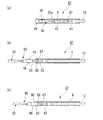
また、鉗子部は、リンク機構部23を介して一対の鉗子片21、22を開閉操作させるものに限らず、図11に示すように、一対の鉗子片21、22に直接第1の操作軸部材41が接続された鉗子部42としてもよく、開拡習性を有する一対の腕部材の基端部を挿入管の先端部内面と接触させた状態で進退操作して開閉操作させる方式のものでも構わない。The technical scope of the present invention is not limited to the above embodiment, and various modifications can be made without departing from the spirit of the present invention.
For example, in the above embodiment, the
Further, the forceps portion is not limited to the one that opens and closes the pair of
さらに、図12に示すように、フック30の代わりに例えば鋼製の撚り線からなるループ状のループワイヤ43が形成された第2の操作軸部材45に、クリップ33の代わりにクリップ46の基端部46AにJ字状の鉤47が形成されたクリップユニット48が着脱可能に係合されたものとし、挿入間本体17内でこのクリップユニット48を例えば3個、直列に配設された結紮装置50としてもよい。
この場合、挿入管本体17の先端側から順に、クリップユニット48、51、52が配されているとし、クリップユニット48と第2の操作軸部材45とが係合され、クリップユニット51と第2の操作軸部材53とが係合され、クリップユニット52と第2の操作軸部材55とが係合されているとする。Further, as shown in FIG. 12, instead of the
In this case, it is assumed that the
このとき、第2の操作軸部材45は、クリップユニット51、52の締付リング36内を貫通して配され、第2の操作軸部材53は、クリップユニット52の締付リング36内を貫通して配されている。また、クリップユニット48、51の締付リング36は、操作管16に具備される短管32でなく、それぞれクリップユニット51、52の先端で係止されている。 At this time, the second
この結紮装置50も、上記の実施形態と同様の作用・効果を奏する。
すなわち、第1の操作軸部材11を操作して一対の鉗子片21、22にて患部6を把持した状態で第2の操作軸部材45を牽引操作してクリップユニット48を閉脚させることによって、患部6を確実に結紮することができる。また、一対の鉗子片21、22による患部の把持と、第2の操作軸部材53の牽引操作によってクリップユニット51による結紮処置を行い、さらに、一対の鉗子片21、22による患部の把持と、第2の操作軸部材55の牽引操作によってクリップユニット51による結紮処置を繰り返すことによって、患部の複数箇所或いは異なる複数の患部を連続して結紮することができる。This
That is, by operating the first operating shaft member 11 and gripping the
また、図13に示すようなクリップユニット56を使用する結紮装置57としてもよい。
このクリップユニット56は、上述したクリップ33と円柱棒状の連結部材58と締付リング60とを備えている。連結部材58の一方の端部58aは他方の端部58bよりも小さい外径に形成されており、先端にクリップユニット56と係合される突出部61が配設されている。連結部材58の他方の端部58bには、二股状に分岐されて切欠部62を有する把持部63が形成されている。締付リング60の外周部には、先端側から基端側に向かって漸次径が大きくなるようにテーパ状に形成され、径方向に突没自在な一対の突没ウイング65、66が配設されている。Moreover, it is good also as the
The
第2の操作軸部材13の先端には、図14及び図15(a)に示すように、矢尻フック67が設けられている。この矢尻フック67は、先端が円錐形状に形成されており、把持部63と係合されることによってクリップユニット56と第2の操作軸部材13とが接続される。
なお、この結紮装置57には、操作管16に該当するものがなく、挿入管8内に第2の操作軸部材13が配設されている。As shown in FIGS. 14 and 15A, an
The ligating
この結紮装置57も上記と同様の作用・効果を奏する。
すなわち、第2の操作軸部材13を先端側に押出して、図15(b)に示すように、クリップユニット56を挿入管8の内部から先端側へ突き出す。このとき、一対の突没ウイング65、66が挿入管8の内面との接触状態から解放されて、先端カバー20の径外方向に突出するとともに、図16(a)に示すように、一対の腕部材3、5を開脚させる。This
That is, the second
そして、第2の操作軸部材13を基端側へ引き戻すと、図15(c)に示すように、一対の突没ウイング65、66の基端側側面が先端カバー20の端面に接触して一旦停止する。さらに第2の操作軸部材13を基端側に引き戻すと、図16(b)に示すように、締付リング60は一対の突没ウイング65、66によって先端カバー20に係止された状態で、連結部材58とともにクリップ33の基端部33A及び一対の嵌動部3a、5aが締付リング60内に引き込まれ、一対の腕部3、5が最大開脚する。 Then, when the second
この状態で、第1の操作軸部材11を牽引操作して一対の鉗子片21、22にて患部6を把持する。
そして、患部6を把持しながら、第2の操作軸部材13を再び引き込むと、図16(c)に示すように、一対の腕部材3、5が締付リング60内に引き込まれて閉脚する。
さらに、第2の操作軸部材13を引き込むと、図16(d)に示すように、連結部材58が軸方向に破断してクリップ33と第2の操作軸部材13との結合が解除され、クリップ33は結紮装置57から患部を挟んだ状態で離脱して体内に留置される。In this state, the first operation shaft member 11 is pulled and the
Then, when the second
Further, when the second
1、50、57 結紮装置
3、5 一対の腕部材
6 患部(生体組織)
7、48、51、52、56 クリップユニット(結紮部)
8 挿入管
10、42 鉗子部
11、41 第1の操作軸部材
12 第1の操作機構
13、45、53、55 第2の操作軸部材
15 第2の操作機構
16 操作管
21、22 一対の鉗子片
25 スリット
1, 50, 57
7, 48, 51, 52, 56 Clip unit (ligation part)
8
Claims (4)
Translated fromJapanese該挿入管の先端側に互いに対向して開閉自在に設けられ生体組織を把持する鉗子部と、
前記挿入管の内部に挿通された第1の操作軸部材を介して前記鉗子部と接続され、前記第1の操作軸部材の進退操作によって前記鉗子部を開閉操作する第1の操作機構と、
前記挿入管の先端側に前記鉗子部と同軸に設けられ、開拡習性を有して互いに対向した一対の腕部材を閉じて生体組織を結紮する結紮部と、
前記挿入管の内部に挿通された第2の操作軸部材を介して前記結紮部に接続され、前記第2の操作軸部材の進退操作によって前記一対の腕部材を閉じるとともに前記結紮部を離脱可能な第2の操作機構とを備え、
前記鉗子部は、前記結紮部が前記生体組織を結紮する前の状態において、前記結紮部の腕部材と干渉せずに前記生体組織を把持可能であることを特徴とする結紮装置。An insertion tube extending in one direction;
A forceps portion that is provided on the distal end side of the insertion tube so as to be openable and closable and grips a living tissue;
A first operation mechanism that is connected to the forceps portion via a first operation shaft member inserted into the insertion tube, and that opens and closes the forceps portion by advancing and retracting the first operation shaft member;
A ligation portion thatis provided coaxially with the forceps portion on the distal end side of the insertion tubeand has a spreadability and closes a pair of arm members facing each other to ligate a living tissue;
Connected to the ligation part via a second operation shaft member inserted into the insertion tube, and the pair of arm members can be closed and the ligation part can be detached by advancing / retreating operation of the second operation shaft member A second operation mechanism,
Theligature apparatus , wherein the forceps part is capable of gripping the living tissue without interfering with an arm member of the ligating partin a state before the ligating part ligates the living tissue.
前記第2の操作軸部材が前記操作管の内部に進退自在に挿通されていることを特徴とする請求項1に記載の結紮装置。An operation tube inserted through the insertion tube;
The ligation apparatus according to claim 1, wherein the second operation shaft member is inserted into the operation tube so as to be able to advance and retract.
前記結紮部が、前記スリット内で開閉可能とされることを特徴とする請求項1又は2に記載の結紮装置。The forceps portion includes a pair of forceps pieces that can be opened and closed, and each forceps piece is formed with a slit that divides the tip into two branches,
The ligation apparatus according to claim 1 or 2, wherein the ligation part is openable and closable within the slit.
Priority Applications (4)
| Application Number | Priority Date | Filing Date | Title |
|---|---|---|---|
| JP2003270527AJP4266738B2 (en) | 2003-07-02 | 2003-07-02 | Ligation device |
| DE602004015535TDE602004015535D1 (en) | 2003-07-02 | 2004-06-30 | Device for ligature |
| EP04015391AEP1493392B1 (en) | 2003-07-02 | 2004-06-30 | Ligation apparatus |
| US10/881,487US7976552B2 (en) | 2003-07-02 | 2004-06-30 | Ligation apparatus |
Applications Claiming Priority (1)
| Application Number | Priority Date | Filing Date | Title |
|---|---|---|---|
| JP2003270527AJP4266738B2 (en) | 2003-07-02 | 2003-07-02 | Ligation device |
Publications (2)
| Publication Number | Publication Date |
|---|---|
| JP2005021587A JP2005021587A (en) | 2005-01-27 |
| JP4266738B2true JP4266738B2 (en) | 2009-05-20 |
Family
ID=33432377
Family Applications (1)
| Application Number | Title | Priority Date | Filing Date |
|---|---|---|---|
| JP2003270527AExpired - Fee RelatedJP4266738B2 (en) | 2003-07-02 | 2003-07-02 | Ligation device |
Country Status (4)
| Country | Link |
|---|---|
| US (1) | US7976552B2 (en) |
| EP (1) | EP1493392B1 (en) |
| JP (1) | JP4266738B2 (en) |
| DE (1) | DE602004015535D1 (en) |
Families Citing this family (77)
| Publication number | Priority date | Publication date | Assignee | Title |
|---|---|---|---|---|
| DE602006004974D1 (en)* | 2005-03-11 | 2009-03-12 | Wilson Cook Medical Inc | DEVICE WITH MULTIPLE CLAMPS |
| JP5019723B2 (en)* | 2005-06-30 | 2012-09-05 | オリンパスメディカルシステムズ株式会社 | Incision forceps |
| KR100780196B1 (en)* | 2006-02-27 | 2007-11-27 | 삼성전기주식회사 | LED package, circuit board for LED package and manufacturing method thereof |
| JP5175833B2 (en)* | 2006-03-10 | 2013-04-03 | クック メディカル テクノロジーズ エルエルシー | Medical device capable of drawing target tissue into clip arm housing chamber |
| US20100228096A1 (en)* | 2009-03-06 | 2010-09-09 | Ethicon Endo-Surgery, Inc. | Methods and devices for providing access into a body cavity |
| US20070241866A1 (en)* | 2006-04-13 | 2007-10-18 | Troy Cool | Wireless service tool for automated protection systems |
| EP2020925B1 (en)* | 2006-06-01 | 2013-07-10 | Cook Medical Technologies LLC | Release mechanisms for a clip device |
| ATE547143T1 (en)* | 2006-07-14 | 2012-03-15 | Cook Medical Technologies Llc | PAPILLA SPREADERS |
| US8226667B2 (en) | 2006-10-05 | 2012-07-24 | Tyco Healthcare Group Lp | Axial stitching device |
| JP5481194B2 (en) | 2006-10-05 | 2014-04-23 | コヴィディエン リミテッド パートナーシップ | Flexible endoscopic suturing device |
| JP5244816B2 (en) | 2006-12-05 | 2013-07-24 | クック メディカル テクノロジーズ エルエルシー | Combination therapy hemostatic clip |
| US8062306B2 (en)* | 2006-12-14 | 2011-11-22 | Ethicon Endo-Surgery, Inc. | Manually articulating devices |
| US8986326B2 (en) | 2007-01-26 | 2015-03-24 | Olympus Medical Systems Corp. | Gasper and grasping tool |
| US7655004B2 (en) | 2007-02-15 | 2010-02-02 | Ethicon Endo-Surgery, Inc. | Electroporation ablation apparatus, system, and method |
| US8133242B1 (en) | 2007-04-27 | 2012-03-13 | Q-Tech Medical Incorporated | Image-guided extraluminal occlusion |
| US8579897B2 (en) | 2007-11-21 | 2013-11-12 | Ethicon Endo-Surgery, Inc. | Bipolar forceps |
| US20090112059A1 (en) | 2007-10-31 | 2009-04-30 | Nobis Rudolph H | Apparatus and methods for closing a gastrotomy |
| US8864776B2 (en) | 2008-04-11 | 2014-10-21 | Covidien Lp | Deployment system for surgical suture |
| EP2113208A3 (en)* | 2008-05-02 | 2010-01-20 | Fujifilm Corporation | Multiple clip device and multiple clip application apparatus |
| US8771260B2 (en) | 2008-05-30 | 2014-07-08 | Ethicon Endo-Surgery, Inc. | Actuating and articulating surgical device |
| US8906035B2 (en) | 2008-06-04 | 2014-12-09 | Ethicon Endo-Surgery, Inc. | Endoscopic drop off bag |
| US8403926B2 (en) | 2008-06-05 | 2013-03-26 | Ethicon Endo-Surgery, Inc. | Manually articulating devices |
| US8628545B2 (en) | 2008-06-13 | 2014-01-14 | Covidien Lp | Endoscopic stitching devices |
| US20110040308A1 (en) | 2008-06-13 | 2011-02-17 | Ramiro Cabrera | Endoscopic Stitching Devices |
| US8888792B2 (en) | 2008-07-14 | 2014-11-18 | Ethicon Endo-Surgery, Inc. | Tissue apposition clip application devices and methods |
| US9679499B2 (en)* | 2008-09-15 | 2017-06-13 | Immersion Medical, Inc. | Systems and methods for sensing hand motion by measuring remote displacement |
| US8157834B2 (en) | 2008-11-25 | 2012-04-17 | Ethicon Endo-Surgery, Inc. | Rotational coupling device for surgical instrument with flexible actuators |
| US8361066B2 (en) | 2009-01-12 | 2013-01-29 | Ethicon Endo-Surgery, Inc. | Electrical ablation devices |
| US20100228090A1 (en)* | 2009-03-06 | 2010-09-09 | Ethicon Endo-Surgery, Inc. | Methods and devices for providing access into a body cavity |
| US9737334B2 (en)* | 2009-03-06 | 2017-08-22 | Ethicon Llc | Methods and devices for accessing a body cavity |
| USD708746S1 (en) | 2009-06-10 | 2014-07-08 | Covidien Lp | Handle for surgical device |
| US8490713B2 (en) | 2009-10-06 | 2013-07-23 | Covidien Lp | Handle assembly for endoscopic suturing device |
| US9474540B2 (en) | 2009-10-08 | 2016-10-25 | Ethicon-Endo-Surgery, Inc. | Laparoscopic device with compound angulation |
| US20110098704A1 (en) | 2009-10-28 | 2011-04-28 | Ethicon Endo-Surgery, Inc. | Electrical ablation devices |
| US8608652B2 (en) | 2009-11-05 | 2013-12-17 | Ethicon Endo-Surgery, Inc. | Vaginal entry surgical devices, kit, system, and method |
| US8496574B2 (en) | 2009-12-17 | 2013-07-30 | Ethicon Endo-Surgery, Inc. | Selectively positionable camera for surgical guide tube assembly |
| US9028483B2 (en) | 2009-12-18 | 2015-05-12 | Ethicon Endo-Surgery, Inc. | Surgical instrument comprising an electrode |
| US8506564B2 (en) | 2009-12-18 | 2013-08-13 | Ethicon Endo-Surgery, Inc. | Surgical instrument comprising an electrode |
| CN102762157B (en) | 2009-12-22 | 2015-04-01 | 库克医学技术有限责任公司 | Medical device with detachable pivotable caliper |
| US10010336B2 (en)* | 2009-12-22 | 2018-07-03 | Cook Medical Technologies, Inc. | Medical devices with detachable pivotable jaws |
| US9005198B2 (en) | 2010-01-29 | 2015-04-14 | Ethicon Endo-Surgery, Inc. | Surgical instrument comprising an electrode |
| US8211121B1 (en) | 2010-03-06 | 2012-07-03 | Q-Tech Medical Incorporated | Methods and apparatus for image-guided extraluminal occlusion using clamping jaws |
| US9226760B2 (en) | 2010-05-07 | 2016-01-05 | Ethicon Endo-Surgery, Inc. | Laparoscopic devices with flexible actuation mechanisms |
| US8562592B2 (en) | 2010-05-07 | 2013-10-22 | Ethicon Endo-Surgery, Inc. | Compound angle laparoscopic methods and devices |
| US8460337B2 (en) | 2010-06-09 | 2013-06-11 | Ethicon Endo-Surgery, Inc. | Selectable handle biasing |
| EP2627264B1 (en) | 2010-10-11 | 2015-06-17 | Cook Medical Technologies LLC | Medical devices with detachable pivotable jaws |
| BR112013008763B1 (en) | 2010-10-11 | 2021-02-17 | Cook Medical Technologies LLC. | medical device for engaging a tissue |
| US8764774B2 (en) | 2010-11-09 | 2014-07-01 | Cook Medical Technologies Llc | Clip system having tether segments for closure |
| US10092291B2 (en) | 2011-01-25 | 2018-10-09 | Ethicon Endo-Surgery, Inc. | Surgical instrument with selectively rigidizable features |
| US8968340B2 (en) | 2011-02-23 | 2015-03-03 | Covidien Lp | Single actuating jaw flexible endolumenal stitching device |
| US9254169B2 (en) | 2011-02-28 | 2016-02-09 | Ethicon Endo-Surgery, Inc. | Electrical ablation devices and methods |
| US9314620B2 (en) | 2011-02-28 | 2016-04-19 | Ethicon Endo-Surgery, Inc. | Electrical ablation devices and methods |
| US9233241B2 (en) | 2011-02-28 | 2016-01-12 | Ethicon Endo-Surgery, Inc. | Electrical ablation devices and methods |
| US9049987B2 (en) | 2011-03-17 | 2015-06-09 | Ethicon Endo-Surgery, Inc. | Hand held surgical device for manipulating an internal magnet assembly within a patient |
| EP2755576B1 (en) | 2011-09-15 | 2019-05-22 | Teleflex Medical Incorporated | Automatic surgical ligation clip applier |
| EP2755578A2 (en) | 2011-09-15 | 2014-07-23 | Teleflex Medical Incorporated | Manual surgical ligation clip applier |
| DE102012007647A1 (en)* | 2012-04-18 | 2013-10-24 | Karl Storz Gmbh & Co. Kg | Tool for a medical instrument |
| US9427255B2 (en) | 2012-05-14 | 2016-08-30 | Ethicon Endo-Surgery, Inc. | Apparatus for introducing a steerable camera assembly into a patient |
| US9078662B2 (en) | 2012-07-03 | 2015-07-14 | Ethicon Endo-Surgery, Inc. | Endoscopic cap electrode and method for using the same |
| US9545290B2 (en) | 2012-07-30 | 2017-01-17 | Ethicon Endo-Surgery, Inc. | Needle probe guide |
| US9572623B2 (en) | 2012-08-02 | 2017-02-21 | Ethicon Endo-Surgery, Inc. | Reusable electrode and disposable sheath |
| US10314649B2 (en) | 2012-08-02 | 2019-06-11 | Ethicon Endo-Surgery, Inc. | Flexible expandable electrode and method of intraluminal delivery of pulsed power |
| US9277957B2 (en) | 2012-08-15 | 2016-03-08 | Ethicon Endo-Surgery, Inc. | Electrosurgical devices and methods |
| US10098527B2 (en) | 2013-02-27 | 2018-10-16 | Ethidcon Endo-Surgery, Inc. | System for performing a minimally invasive surgical procedure |
| US9468434B2 (en) | 2014-06-03 | 2016-10-18 | Covidien Lp | Stitching end effector |
| US11337715B2 (en) | 2015-03-26 | 2022-05-24 | United States Endoscopy Group, Inc. | Endoscopic grasping device |
| US10092286B2 (en) | 2015-05-27 | 2018-10-09 | Covidien Lp | Suturing loading unit |
| US10542970B2 (en) | 2016-05-31 | 2020-01-28 | Covidien Lp | Endoscopic stitching device |
| US10952742B2 (en)* | 2017-11-28 | 2021-03-23 | Boston Scientific Scimed, Inc. | Self-aligning pullwire for reloadable hemostasis clipping device |
| CN108542495B (en)* | 2018-05-11 | 2023-07-25 | 四川大学华西第二医院 | A kind of plastic forceps for fallopian tube repair |
| US11197665B2 (en) | 2018-08-06 | 2021-12-14 | Covidien Lp | Needle reload device for use with endostitch device |
| WO2020101877A1 (en)* | 2018-11-15 | 2020-05-22 | Boston Scientific Scimed, Inc. | Stretch hoop coupler for reloadable hemostasis clipping device |
| CN111248970B (en) | 2018-11-30 | 2021-06-18 | 苏州英途康医疗科技有限公司 | Medical instrument |
| CN111248972B (en) | 2018-11-30 | 2021-05-28 | 苏州英途康医疗科技有限公司 | Medical instrument |
| CN111248971B (en) | 2018-11-30 | 2021-06-29 | 苏州英途康医疗科技有限公司 | Medical instrument |
| CN112690864B (en)* | 2019-10-23 | 2022-03-22 | 苏州英途康医疗科技有限公司 | Medical instrument and automatic clamp feeding method |
| US11998187B2 (en)* | 2021-09-10 | 2024-06-04 | Olympus Corporation | Suture method |
Family Cites Families (11)
| Publication number | Priority date | Publication date | Assignee | Title |
|---|---|---|---|---|
| US3989049A (en)* | 1973-07-30 | 1976-11-02 | In Bae Yoon | Method of applying an elastic ring to an anatomical tubular structure |
| US5026379A (en)* | 1989-12-05 | 1991-06-25 | Inbae Yoon | Multi-functional instruments and stretchable ligating and occluding devices |
| DE3941108C1 (en)* | 1989-12-13 | 1991-06-27 | Richard Wolf Gmbh, 7134 Knittlingen, De | |
| US5015249A (en)* | 1989-12-26 | 1991-05-14 | Nakao Naomi L | Endoscopic stapling device and method |
| US5156609A (en)* | 1989-12-26 | 1992-10-20 | Nakao Naomi L | Endoscopic stapling device and method |
| JPH05184535A (en) | 1991-07-24 | 1993-07-27 | Olympus Optical Co Ltd | Multifunctional treating-implement |
| JPH0574508A (en) | 1991-09-13 | 1993-03-26 | Furukawa Electric Co Ltd:The | Superconducting wire connection method |
| JPH0574508U (en) | 1992-03-16 | 1993-10-12 | オリンパス光学工業株式会社 | Clip applicator |
| US5464416A (en) | 1992-11-10 | 1995-11-07 | Ethicon, Inc. | Ligating clip |
| JP3523712B2 (en) | 1995-04-13 | 2004-04-26 | オリンパス株式会社 | Ligation device |
| US6716226B2 (en)* | 2001-06-25 | 2004-04-06 | Inscope Development, Llc | Surgical clip |
- 2003
- 2003-07-02JPJP2003270527Apatent/JP4266738B2/ennot_activeExpired - Fee Related
- 2004
- 2004-06-30DEDE602004015535Tpatent/DE602004015535D1/ennot_activeExpired - Lifetime
- 2004-06-30EPEP04015391Apatent/EP1493392B1/ennot_activeExpired - Lifetime
- 2004-06-30USUS10/881,487patent/US7976552B2/ennot_activeExpired - Fee Related
Also Published As
| Publication number | Publication date |
|---|---|
| DE602004015535D1 (en) | 2008-09-18 |
| US20050033312A1 (en) | 2005-02-10 |
| US7976552B2 (en) | 2011-07-12 |
| EP1493392B1 (en) | 2008-08-06 |
| EP1493392A1 (en) | 2005-01-05 |
| JP2005021587A (en) | 2005-01-27 |
Similar Documents
| Publication | Publication Date | Title |
|---|---|---|
| JP4266738B2 (en) | Ligation device | |
| JP3776529B2 (en) | Clip device | |
| JP2873366B2 (en) | Forceps | |
| JP6815506B2 (en) | Clip treatment tool | |
| EP3305215B1 (en) | Device for endoscope | |
| EP3298971B1 (en) | Clip device | |
| CN109953800A (en) | A kind of chute-type multi-arm folder | |
| CN108697428A (en) | Clamp box | |
| EP1859747A1 (en) | Suturing and ligating device for medical treatment | |
| JPH05200033A (en) | Subperioneoscope apparatus for applica- tion of endoligature | |
| EP2889008A1 (en) | Suture device | |
| JP2008521559A (en) | System and method for tensioning a suture | |
| JPWO2003053256A1 (en) | Endoscope clip device and endoscope clip used therefor | |
| WO2012039163A1 (en) | Ligature device and clip unit used therein | |
| CN211633453U (en) | Endoscope double-arm tissue clamp capable of being opened and closed repeatedly | |
| CN118986456A (en) | Ligature device | |
| JP2000287981A (en) | Indwelling clip in cavity in living body | |
| JPH04102450A (en) | Clip for living body tissue | |
| JP2015192724A (en) | Hold releasing device of body tissue holding member | |
| CN110547834A (en) | Tendon guide forceps | |
| JPH05212043A (en) | Clipping device | |
| CN210277289U (en) | Chute type multi-arm clamp | |
| JP7182716B2 (en) | Endoscopic treatment tool | |
| CN118303944A (en) | Clamping assembly and endoscope tissue clamp | |
| CN213310023U (en) | Anastomosis clamping sleeve device and endoscope device thereof |
Legal Events
| Date | Code | Title | Description |
|---|---|---|---|
| A621 | Written request for application examination | Free format text:JAPANESE INTERMEDIATE CODE: A621 Effective date:20060623 | |
| A131 | Notification of reasons for refusal | Free format text:JAPANESE INTERMEDIATE CODE: A131 Effective date:20080729 | |
| A521 | Written amendment | Free format text:JAPANESE INTERMEDIATE CODE: A523 Effective date:20080929 | |
| A02 | Decision of refusal | Free format text:JAPANESE INTERMEDIATE CODE: A02 Effective date:20081104 | |
| A521 | Written amendment | Free format text:JAPANESE INTERMEDIATE CODE: A821 Effective date:20081205 | |
| A521 | Written amendment | Free format text:JAPANESE INTERMEDIATE CODE: A523 Effective date:20090105 | |
| A911 | Transfer to examiner for re-examination before appeal (zenchi) | Free format text:JAPANESE INTERMEDIATE CODE: A911 Effective date:20090109 | |
| TRDD | Decision of grant or rejection written | ||
| A01 | Written decision to grant a patent or to grant a registration (utility model) | Free format text:JAPANESE INTERMEDIATE CODE: A01 Effective date:20090127 | |
| A01 | Written decision to grant a patent or to grant a registration (utility model) | Free format text:JAPANESE INTERMEDIATE CODE: A01 | |
| A61 | First payment of annual fees (during grant procedure) | Free format text:JAPANESE INTERMEDIATE CODE: A61 Effective date:20090217 | |
| R151 | Written notification of patent or utility model registration | Ref document number:4266738 Country of ref document:JP Free format text:JAPANESE INTERMEDIATE CODE: R151 | |
| FPAY | Renewal fee payment (event date is renewal date of database) | Free format text:PAYMENT UNTIL: 20120227 Year of fee payment:3 | |
| FPAY | Renewal fee payment (event date is renewal date of database) | Free format text:PAYMENT UNTIL: 20120227 Year of fee payment:3 | |
| FPAY | Renewal fee payment (event date is renewal date of database) | Free format text:PAYMENT UNTIL: 20130227 Year of fee payment:4 | |
| FPAY | Renewal fee payment (event date is renewal date of database) | Free format text:PAYMENT UNTIL: 20140227 Year of fee payment:5 | |
| S531 | Written request for registration of change of domicile | Free format text:JAPANESE INTERMEDIATE CODE: R313531 | |
| R350 | Written notification of registration of transfer | Free format text:JAPANESE INTERMEDIATE CODE: R350 | |
| R250 | Receipt of annual fees | Free format text:JAPANESE INTERMEDIATE CODE: R250 | |
| LAPS | Cancellation because of no payment of annual fees |