JP4266409B2 - Surgical microscope - Google Patents
Surgical microscopeDownload PDFInfo
- Publication number
- JP4266409B2 JP4266409B2JP25555798AJP25555798AJP4266409B2JP 4266409 B2JP4266409 B2JP 4266409B2JP 25555798 AJP25555798 AJP 25555798AJP 25555798 AJP25555798 AJP 25555798AJP 4266409 B2JP4266409 B2JP 4266409B2
- Authority
- JP
- Japan
- Prior art keywords
- image
- microscope
- optical system
- monitor
- observation
- Prior art date
- Legal status (The legal status is an assumption and is not a legal conclusion. Google has not performed a legal analysis and makes no representation as to the accuracy of the status listed.)
- Expired - Fee Related
Links
Images


Landscapes
- Microscoopes, Condenser (AREA)
Description
Translated fromJapanese【0001】
【発明の属する技術分野】
本発明は手術用顕微鏡に関する。
【0002】
【従来の技術】
従来、手術用顕微鏡は、脳外科、耳鼻咽喉科、眼科等の外科手術に用いられており、術部の拡大観察を可能にして手術の能率を向上させるという重要な役割を果たしている。さらに近年では、手術をより確実に行なうため、手術用顕微鏡観察下のみで行なっていた従来の手術に、内視鏡観察が併用されており、手術用顕微鏡観察像と内視鏡観察像とを手術用顕微鏡視野内で同時に観察できることが望まれている。また、内視鏡観察像にとどまらず、術前のCTやMRIの画像および術中の神経モニター等の情報の同時観察も望まれている。
【0003】
このような要望に応えるべく、例えば、 特開昭62−166310号公報には、顕微鏡の観察と第2の観察手段の観察とを顕微鏡視野内で同時に行なうための技術が開示されている。また、特開平3−105305号公報には、顕微鏡と内視鏡の同時観察を実現するための技術が開示されている。
【0004】
【発明が解決しようとする課題】
しかしながら、特開昭62−166310号公報に開示された技術では、顕微鏡の結像面近傍に配置された反射部材によって、顕微鏡観察視野の一部が遮られる。そのため、この遮られた部分の観察をしたい時には、顕微鏡観察視野の遮られていない所に観察点をもってくるために、顕微鏡全体を移動させなければならない。顕微鏡部の全体を移動させる作業は、手術の流れを中断させ、手術効率を低下させる。また、この公報には、顕微鏡結像面と反射部材との位置関係が明示されておらず、図面にあるように反射部材の中心を顕微鏡結像面に配置した時には、反射部材の上方および下方が顕微鏡結像面から離れて焦点が合わなくなり、顕微鏡視野と画像(反射部材によって顕微鏡視野内にとりこまれる第2の観察手段の画像)との境界が明瞭に判別できなくなる。
【0005】
一方、特開平3−105305号公報に開示された技術では、顕微鏡像と内視鏡像とがハーフミラーによって結合されるため、2つの像が重なり、これら2つの像の判別が困難となる。 また、内視鏡が常に顕微鏡の全体に重なっているため、術者は顕微鏡下の作業に集中することができない。
【0006】
本発明は、 前記事情に着目してなされたものであり、その目的とするところは、顕微鏡観察を妨げることなく各種情報の同時観察が行なえるとともに、顕微鏡像と画像情報との境界が明瞭で且つ2つの像の識別を確実に行なうことができる手術用顕微鏡を提供することにある。
【0007】
【課題を解決するための手段】
請求項1に係る発明は、顕微鏡の観察視野画像の領域内における一部領域にモニタ画像を表示する領域を形成し、上記観察視野画像の領域に対する上記モニタ画像を表示する領域の位置を変更する変更手段を備え、
上記変更手段は、上記顕微鏡の光学系の光路における結像位置に上記モニタ画像を反射して観察視野領域に投影する反射部材を配置し、上記反射部材の反射面は上記観察視野画像の光を透過しない反射面とし、上記反射部材の出射面は上記顕微鏡の光学系の光路における結像位置と略同一面上に設置され、更に上記モニタ画像を上記反射部材の反射面に入射させる画像光学系を備え、上記画像光学系は、上記モニタ画像をアフォーカルな光束とするレンズと、このアフォーカルな光束を結像レンズにより上記反射部材の反射面に入射させるとともに上記アフォーカルな光束内で上記結像レンズを移動し、この結像レンズの移動に追従して上記反射部材を上記顕微鏡光学系の光路を横切る向きに上記光路に対し相対的に移動して上記顕微鏡の観察視野画像の領域内における上記モニタ画像の領域の位置を変更するようにしたことを特徴とする手術用顕微鏡である。
請求項2に係る発明は、顕微鏡光学系の結像位置において顕微鏡の観察視野画像の領域内における一部領域にモニタ画像を映し出す液晶板を配置し、この液晶板の位置を変更する変更手段を備え、上記変更手段は、液晶板を傾き移動可能に支持し、顕微鏡光学系の結像位置において上記液晶板を移動させることにより上記顕微鏡の観察視野画像の領域内における上記モニタ画像の領域を変更するようにしたことを特徴とする手術用顕微鏡である。
【0008】
この請求項1に記載の発明によれば、顕微鏡像の一部に投影されたモニタ画像の位置を移動することができ、顕微鏡観察の邪魔にならない位置でモニタ画像の同時観察が行なえる。
【0009】
また、請求項2に記載された発明は、接眼光学系を有する手術用顕微鏡と、モニタ画像を前記接眼光学系に導く画像光学系とを有する手術用顕微鏡において、前記画像光学系は、手術用顕微鏡像と画像光学系によって前記接眼光学系の結像面に投影されたモニタ画像とを仕切るための画像光学系視野絞りを、前記接眼光学系の結像面と概同一位置に有することを特徴とする。
この請求項2に記載の発明によれば、顕微鏡像とモニタ画像との境界が明瞭に観察でき、各々の像を確実に認識できる。
【0010】
【発明の実施の形態】
以下、図面を参照しながら、本発明の実施形態について説明する。
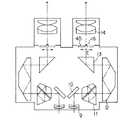
図1〜図5は本発明の第1の実施形態を示している。図1は手術用顕微鏡および内視鏡の全体図を示し、図中1は顕微鏡部、2は左右光路共通の対物レンズ、3は左右一対の変倍光学系をそなえるズーム鏡体、4は接眼鏡筒である。ズーム鏡体3には、図示しない光源およびライトガイドからの光を術部に照射するための照明光学系が内蔵されている。また、図中5は顕微鏡部1を3次元的に支持する架台部、6は内視鏡、7は内視鏡6の観察像を撮影するためのTVカメラ、8はTVカメラ7のCCUである。
【0011】
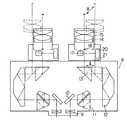
次に、接眼鏡筒4の構成を図2〜図4を用いて説明する。なお、左右光路の構成は同一であるため、片側の光路についてのみ説明する。
接眼鏡筒4はズーム鏡体3と光学的に結合されている。具体的には、接眼鏡筒4には、ズーム鏡体3側から順に、結像レンズ9と、ミラー10と、イメージローテータ11と、偏向プリズム12と、プリズム13と、接眼レンズ14とが配置されている。図中15は接眼レンズ14を保持する接眼レンズ枠である。
【0012】
プリズム13は図2に破線で示されるA方向に移動自在に支持されている。また接眼レンズ14は、プリズム13の移動に伴なって図2に破線で示されるB方向に移動可能に支持されている。21は接眼レンズ14の光軸を中心に回動可能に接眼レンズ枠15に支持された画像光学系保持枠である。
【0013】
図3および図4に詳しく示されるように、画像光学系保持枠21には、画像光学系、すなわち、モニタ20と、レンズ19と、ミラー18と、投影プリズム17とが順次配置されている。投影プリズム17の出射面24は顕微鏡光学系の結像面16の近傍に配置されている。また、投影プリズム17の反射面25にはミラーコートが施されている。
【0014】
画像光学系保持枠21は、公知のクリック機構等により、接眼レンズ枠15に対して90度毎に位置決めが行なえるようになっている。図3中、22は画像光学系保持枠21の回転状態を検出するセンサ、23は公知の画像回転機能を有するビデオミキサである。 ビデオミキサ23は、CCU8から映像信号が入力され、モニタ20に映像信号を出力する。また、センサ22の信号はビデオミキサ23に入力される。
【0015】
次に、上記構成の手術用顕微鏡の作用について説明する。
図示しない光源およびライトガイドからの照明光は、ズーム鏡体3に内蔵された照明光学系により、対物レンズ2を通過して術部に照射される。術部からの光は、対物レンズ2とズーム鏡体3内の変倍光学系とを通過し、アフォーカル光束となって接眼鏡筒4に入射する。接眼鏡筒4に入射した光は、結像レンズ9によって、ミラー10、イメージローテータ11、偏向プリズム12、プリズム13を順次通過し、結像面16に結像する。結像面16の像は接眼レンズ14によって拡大観察される。
【0016】
なお、ここで、接眼鏡筒4の眼幅調整について説明すると、プリズム13がA方向にスライドした時に、接眼レンズ14がB方向に移動することにより、プリズム13のスライドによる光路長の変化がキャンセルされるようになっている。すなわち、本実施形態では、いわゆる公知のイエンチ(Jentzsche)方式によって眼幅の調整が行なわれる。
【0017】
内視鏡6で得られた像は、 TVカメラ7およびCCU8により映像信号となり、ミキサ23を介してモニタ20に映し出される。モニタ20の画像は、レンズ19によりミラー18およびプリズム24を介して、結像面16に結像する。この時の接眼レンズ14による観察像が図5の(a)に示されている。図示のように、結像レンズ9によって結像面16上に結像した顕微鏡像は、プリズム17の反射面25に施されたミラーコートによって遮られる。一方、モニタ20の画像はプリズム17によって顕微鏡像と同一の結像面16に結像するため、観察者は顕微鏡像とモニタ画像とを同時に観察できる。なお、この場合、結像面16の近傍にプリズム17の出射面24が配置されているため、プリズム17の出射面24自体が顕微鏡像とモニタ画像との境界となる。
【0018】
また、本実施形態では、画像光学系保持枠21を回転させると、モニタ画像の位置を変更することができる。図5の(a)の状態から画像光学系保持枠21を反時計回りに90度回転させた時の観察像が図5の(b)に示されている。画像光学系保持枠21が回転されると、センサ22により撮像光学系21の回転が検出され、その信号がビデオミキサ23に送られる。ビデオミキサ23は、センサ22からの信号に基づき、図5の(C)に示すようにモニタ画像を回転補正し、モニタ画像の向きを常に一定に保つ。
【0019】
以上説明したように、本実施形態の手術用顕微鏡によれば、 顕微鏡視野内の一部に投影されたモニタ画像の位置を顕微鏡視野内で移動させることができるため、顕微鏡観察の邪魔にならない位置にモニタ画像を配置することができる。また、顕微鏡像とモニタ画像の境界が明瞭に観察できるため、各々の像の認識が確実に行なえる。
【0020】
なお、画像光学系保持枠21の回転は、本実施形態において手動で行なわれるが、ステッピングモータ等を用いて電動で行なわれるようになっていても良い。この場合、 手を使わずに左右連動でモニタ画像を任意の位置に変更できる。また、ステッピングモータの信号により、画像光学系保持枠21の回転検出が行なえるため、センサ22が不要となる。
【0021】
図6〜図11は本発明の第2の実施形態を示している。なお、本実施形態において第1の実施形態と同一の構成部分については、同一符号を付してその説明を省略する。
【0022】
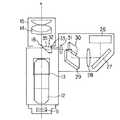
まず、図6〜図9を用いて画像光学系の構成について説明する。なお、左右光路の構成は同一であるため、片側の光路についてのみ説明する。図7に詳しく示されるように、画像光学系は、モニタ26と、ミラー27と、レンズ28と、ミラー29と、ミラー30と、結像レンズ31と、投影プリズム32とからなる。ミラー29からミラー30に向かう光束の進行方向は、眼幅調整時に接眼レンズ14が移動する方向(B方向)と同じである。ミラー30と結像レンズ31と投影プリズム32は、眼幅調整時に接眼レンズ14と一体で移動するように、接眼レンズ枠15に支持されている。また、これらの光学要素30,31,32は、軸33に沿って、図8に破線で示されるC方向(結像面16と平行)に移動できる。投影プリズム32の出射面35は結像面16の近傍に配置され、出射面35の外周には図9に示すようにコーティングによって視野マスク36が施されている。
【0023】
次に、上記構成の手術用顕微鏡の作用について説明する。
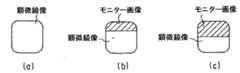
モニタ26の画像は、ミラー27で反射されるとともに、レンズ28によりアフォーカル光線となってミラー29,30で反射され、結像レンズ31により投影プリズム32を介して結像面16上に結像される。この時の観察像が図11の(a)に示されている。図示のように、投影プリズム32の出射面35には視野マスク36が施されているため、顕微鏡像とモニタ画像との境界には縁取りが入る。また、図11の(b)に示すように、内視鏡6がモニタ画像の裏側に隠れてしまう場合には、プリズム32と結像レンズ31とミラー30とを軸33に沿って図8に示される破線位置へと移動させれば良い。これにより、図11の(c)に示されるような観察像が得られる。このような観察像が得られる理由は、図10に示される光学原理に基づく。すなわち、モニタ26の画像はレンズ28によってアフォーカル光束となるため、アフォーカル光束内での結像レンズ31の移動であれば、結像面16上にモニタ26の画像を投影することができる。
【0024】
以上説明したように、本実施形態の手術用顕微鏡によれば、第1の実施形態とほぼ同様の効果が得られるとともに、モニタ画像を移動する時に画像光学系全体を移動させる必要がないため、接眼鏡筒4を小型にできる。また、顕微鏡像とモニタ画像との境界に縁取りがされているため、第1の実施形態に比べ、各々の像の判別が容易となる。これは、特に、左右の視差によって境界部(顕微鏡像とモニタ画像との境界部)の判別が行ないづらくなる3D画像投影時(モニタ画像として3D画像を投影した時)に有効である。
【0025】
なお、本実施形態では、視野マスクが四角形状の縁取りとして形成されているが、円形の視野マスクでも同様の効果が得られる。
図12〜図15は本発明の第3の実施形態を示している。なお、本実施形態において、第1および第2の実施形態と同一の構成部分については、同一符号を付してその説明を省略する。
【0026】
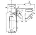
まず、図12を用いて本実施形態の構成を説明する。投影プリズム32と結像レンズ31は、 図中破線で示すD方向(光軸方向)に移動可能に支持されている。38は投影プリズム32および結像レンズ31の移動量を検出するセンサであり、センサ31の信号はビデオミキサ39に入力される。ビデオミキサ39は画像の表示範囲や表示倍率を変更できる機能を有しており、内視鏡画像および図示しない神経モニタからの波形情報が入力される。ビデオミキサ39からの映像出力信号はモニタ26に送信される。モニタ26に送信される映像は、内視鏡像または神経モニタ波形であり、これらは選択可能となっている。
【0027】
次に、上記構成の手術用顕微鏡の作用について説明する。
図14の(a)は、投影プリズム32および結像レンズ31が図12に実線で示される位置にある場合の観察像を示している。この時のビデオミキサ39からの映像出力信号としては内視鏡像が選択されており、モニタ26の表示は図15の(a)に示されるように画面全体に映し出されている。次に、神経モニタの波形を観察する時には、投影プリズム32および結像レンズ31を図12に破線で示される位置に移動させる。この時、センサ38により投影プリズム32および結像レンズ31の移動が検出され、その検出信号がセンサ38からビデオミキサ39に送られる。これにより、ビデオミキサ39の映像出力信号が切り替わり、モニタ26の表示範囲は図15の(b)に示されるように、上半分になる。すなわち、投影プリズム32が接眼レンズ14で観察される範囲に対応してモニタ26の表示範囲が切り替わる。この時の観察像が図14の(b)に示されている。この場合の光学原理は、図13に示される通りである。すなわち、モニタ26の像はレンズ28によりアフォーカル光束となるため、結像レンズ31が光軸方向に移動した場合でも、結像レンズ31から結像面16までの距離は変化しない。したがって、画像光学系の光路長が変化した場合でも、モニタ26の画像は結像面16上に結像する。
【0028】
以上説明したように、本実施形態の手術用顕微鏡によれば、モニタ画像に投影される画像の種類によって、顕微鏡視野内でのモニタ画像表示の大きさを変えられるため、神経モニタ波形のようにモニタ画像表示が小さくても支障がない場合には、顕微鏡像のケラレを最小限にすることができる。また、画像光学系全体を移動させずにモニタ画像表示の大きさを変えられるため、接眼鏡筒4を小型化できる。
【0029】
図16および図17は本発明の第4の実施形態を示している。なお、本実施形態において、第1〜第3の実施形態と同一の構成部分については、同一符号を付してその説明を省略する。
【0030】
図16および図17に示されるように、本実施形態に係る手術用顕微鏡は液晶モニタ40を有している。 この液晶モニタ40は、結像面16の近傍に配置され、結像面16と平行な平面内を横方向(図16に矢印で示されるE方向)および縦方向(図17に矢印で示されるF方向)に移動可能に支持されている。
【0031】
次に、上記構成の手術用顕微鏡の作用について説明する。
液晶モニタ40が 図16に実線で示される位置に配置されている時の観察像は、図11の(a)に示される観察像と同様になる。すなわち、顕微鏡像の一部が液晶モニタ40によって遮られる。無論、液晶モニタ40が結像面16の近傍に配置されているため、 顕微鏡像とモニタ画像との同時観察は可能である。一方、液晶モニタ40が図16に破線で示される位置に移動されると、観察像は図11の(c)に示されるようなものとなる。また、液晶モニタ40が図17に実線で示される位置に配置されている時の観察像は図14の(a)と同様であり、この実線位置から破線位置へと液晶モニタ40が移動されると、図14の(b)に示されるような観察像が得られる。
【0032】
以上説明したように、本実施形態の手術用顕微鏡によれば、第2および第3の実施形態とほぼ同様の効果が得られるとともに、液晶モニタ40それ単体を移動させるだけで顕微鏡視野内におけるモニタ画像(表示)の位置および大きさを変更することができるため、装置を小型化できる。
【0033】
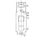
図18および図19は本発明の第5の実施形態を示している。なお、本実施形態において、第4の実施形態と同一の構成部分については、同一符号を付してその説明を省略する。
【0034】
図18に示されるように、本実施形態に係る手術用顕微鏡は液晶モニタ43を有している。この液晶モニタ43は、結像面16の近傍に配置され、回転軸44を中心に矢印G方向に回動可能に支持されている。
【0035】
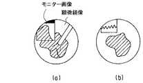
図19の(a)は、液晶モニタ43が図18に実線で示される位置に配置されている時の観察像を示している。図示のように、液晶モニタ43には文字情報が投影されている。 この実線位置から液晶モニタ43が破線位置へと移動されると、図19の(b)に示されるような観察像が得られる。
【0036】
このように、本実施形態の手術用顕微鏡によれば、 顕微鏡視野内におけるモニタ画像の大きさを液晶モニタ43の回転移動によって変更することができるため、文字情報のように液晶モニタ43の斜め方向からの観察でも支障がない場合には、構成を簡単にすることができ、軽量かつ安価な装置を提供できる。
【0037】
なお、本実施形態では、液晶モニタ43の観察を斜め方向から行なうようにしたが、液晶モニタ43の回転量を検出する検出手段を設け、この検出手段からの情報によって液晶モニタ43の表示を図20の(a)(b)に示されるように補正しても良い。
【0038】
図21〜図23は本発明の第6の実施形態を示している。図21および図22に示されるように、ズーム鏡体と光学的に結合される接眼鏡筒4は、第1の実施形態と同様、左右一対の光路を有している。なお、左右光路の構成は同一であるため、以下、片側の光路についてのみ説明する。
【0039】
接眼鏡筒4には、 ズーム鏡体3側から順に、結像レンズ46と、ミラー47と、イメージローテータ48と、偏向プリズム49と、プリズム50と、接眼レンズ52とが配置されている。プリズム50の反射面55にはミラーコートが施されている。また、プリズム50は、図22に矢印で示されるH方向に移動可能に支持されている。また、接眼レンズ52の光軸の延長線上には、投影レンズ54と液晶モニタ53とが配置されている。この場合、投影レンズ54は液晶モニタ53の画像を結像面51に結像するべく配置されている。
【0040】
次に、上記構成の手術用顕微鏡の作用について説明する。
図示しないズーム鏡体からの光束は、 結像レンズ46によって、ミラー47とイメージローテータ48と偏向プリズム49とプリズム50とを順次に通過して、結像面51に結像する。結像面51の像は接眼レンズ52によって拡大観察される。この場合、プリズム50が図22の実線位置に配置されている時には、液晶モニタ53からの光束は、プリズム50の反射面55に施されたミラーコートによって遮られるため、結像面51に届かない。この時の観察像が図23の(a)に示されている。 次に、プリズム50を図22の破線位置へと移動させると、液晶モニタ53からの光束の一部が結像面51に結像する。この時の観察像が図23の(b)に示されている。この状態からさらにプリズム50を移動させると、図23の(c)に示されるような観察像が得られる。そして、プリズム50が顕微鏡光路から完全に退避した状態では、観察像はモニタ画像のみとなる。
【0041】
このように、本実施形態の手術用顕微鏡によれば、顕微鏡視野内における顕微鏡像とモニタ画像との投影比率を任意に変更することができる。
なお、以上説明してきた技術内容によれば、以下に示すような各種の構成が得られる。
【0042】
1.顕微鏡視野内の一部に画像を投影するための画像投影光学系を備えた手術用顕微鏡において、顕微鏡視野内における投影画像の位置を変更する変更手段を備えていることを特徴とする手術用顕微鏡。
この第1項に記載の技術によれば、顕微鏡像の一部に投影されたモニタ画像の位置を移動することができ、顕微鏡観察の邪魔にならない位置でモニタ画像の同時観察が行なえる。
【0043】
2.接眼光学系を有する手術用顕微鏡とモニタ画像を前記接眼光学系に導く画像光学系とを有する手術用顕微鏡において、前記画像光学系は、手術用顕微鏡像と画像光学系によって前記接眼光学系の結像面に投影されたモニタ画像とを仕切るための画像光学系視野絞りを、前記接眼光学系の結像面と概同一位置に有することを特徴とする手術用顕微鏡。
この第2項に記載の技術によれば、顕微鏡像とモニタ画像との境界が明瞭に観察でき、各々の像を確実に認識できる。
【0044】
3.接眼光学系を有する顕微鏡光学系と、モニタ画像を前記接眼光学系の結像面に投影する画像光学系とを有する手術用顕微鏡において、前記接眼光学系の観察範囲内で前記接眼光学系の結像面近傍に投影されたモニタ画像を移動させるための光学部材移動手段を有することを特徴とする手術用顕微鏡。
4.接眼光学系を有する手術用顕微鏡とモニタ画像を前記接眼光学系へ導く画像光学系とを有する手術用顕微鏡において、前記画像光学系の一部が前記接眼光学系の結像面近傍に配置され且つ前記接眼光学系の観察範囲内で移動することを特徴とする手術用顕微鏡。
この第4項に記載の技術によれば、顕微鏡像の一部に投影されたモニタ画像の位置を移動することができ、顕微鏡観察の邪魔にならない位置でモニタ画像の同時観察が行なえる。
【0045】
5.前記画像光学系は、前記接眼光学系の前記結像面に対して平行に移動することを特徴とする第4項に記載の手術用顕微鏡。
6.前記画像光学系が前記接眼光学系の光軸を中心に回転することを特徴とする第4項に記載の手術用顕微鏡。
第5項および第6項に記載の技術によれば、モニタ画像の結像位置が常に顕微鏡結像面と一致した状態で、モニタ画像の移動が行なえる。
【0046】
7.接眼光学系を有する手術用顕微鏡と、モニタ画像を前記接眼光学系へ導く画像光学系とを具備し、前記画像光学系が、前記モニタ画像をアフォーカル光束とするリレー光学系と、前記アフォーカル光束を前記接眼光学系の結像面に結像する投影光学系とで構成され、前記投影光学系の一部が前記接眼光学系の観察範囲に配置された手術用顕微鏡において、
前記投影光学系は、前記リレー光学系から出射された前記アフォーカル光束の光束内で且つ前記接眼光学系の観察範囲内で移動することを特徴とする手術用顕微鏡。
この第7項に記載の技術によれば、 顕微鏡像内でモニタ画像を移動させる際に、画像光学系全体を移動させる必要がないため、接眼鏡筒の小型化を図ることができる。
【0047】
8.前記投影光学系は前記アフォーカル光束の光軸に対し垂直方向に移動することを特徴とする第7項に記載の手術用顕微鏡。
この第8項に記載の技術によれば、顕微鏡像内でのモニタ画像の観察者に対する水平方向移動が、画像光学系全体を移動させることなく行なえるため、接眼鏡筒の小型化が図れる。
【0048】
9.前記投影光学系は前記アフォーカル光束の光軸に対し平行方向に移動することを特徴とする第7項に記載の手術用顕微鏡。
この第9項に記載の技術によれば、顕微鏡像内でのモニタ画像の観察者に対する垂直方向移動が、画像光学系全体を移動させることなく行なえるため、接眼鏡筒の小型化が図れる。
【0049】
10.接眼光学系を有する顕微鏡光学系と、前記接眼光学系の観察範囲内で且つ結像面の近傍にモニタを備えた手術用顕微鏡において、前記モニタが前記接眼光学系の範囲内で移動することを特徴とする手術用顕微鏡。
11.前記モニタが前記接眼光学系の結像面に対して平行に移動することを特徴とする第10項に記載の手術用顕微鏡。
12.前記モニタが前記接眼光学系の結像面に平行な回転軸回りに回転移動することを特徴とする第10項に記載の手術用顕微鏡。
【0050】
13.接眼光学系と、この接眼光学系に光束を導くための反射部材を接眼光学系の結像面の近傍に備えた顕微鏡光学系と、前記接眼光学系にモニタ画像を導くための画像光学系とを有する手術用顕微鏡において、
前記反射部材は、前記接眼光学系の結像面と画像光学系との間に配置され、前記接眼光学系の結像面に対して平行に移動することを特徴とする手術用顕微鏡。
【0051】
14.前記画像光学系の移動を検知する検知手段と、前記検知手段の検知結果により前記モニタ画像の表示状態を変更する制御手段とを有することを特徴とする第1項または第3項〜第13項のいずれか1項に記載の手術用顕微鏡。
この第14項に記載の技術によれば、顕微鏡像内のモニタ画像表示位置および範囲の変更に伴い、モニタ表示が切り替わるため、顕微鏡像内のモニタ画像は、常に一定の向きで表示され、また、表示範囲に対応した大きさで観察される。
【0052】
15.前記画像光学系視野絞りは、前記画像光学系の一部を構成するプリズムの出射面に施され、このプリズムは、前記モニタ画像を前記接眼光学系の結像面に投影するために前記接眼光学系の観察範囲内に配置されていることを特徴とする第2項に記載の手術用顕微鏡。
この第15項に記載の技術によれば、顕微鏡像とモニタ画像との境界がプリズム自体により得られるため、小型化およびコストの低減を図ることができる。
16.光学部材の移動は左右連動して移動することを特徴とする第1項または第3項〜第13項のいずれか1項に記載の手術用顕微鏡。
【0053】
【発明の効果】
以上説明したように、本発明の手術用顕微鏡によれば、顕微鏡観察の所望の位置を妨げることなく各種情報の同時観察がおこなえるとともに、顕微鏡とその一部に投影された画像情報の境界を明瞭にし、両方の像の識別を確実に行なうことができる。
【図面の簡単な説明】
【図1】手術用顕微鏡および内視鏡の全体図である。
【図2】本発明の第1の実施形態に係る手術用顕微鏡の接眼鏡筒の正面図である。
【図3】図2の手術用顕微鏡の接眼レンズ部の上面図である。
【図4】図2の手術用顕微鏡の接眼レンズ部の側面図である。
【図5】図2の手術用顕微鏡の観察状態を示す図である。
【図6】本発明の第2の実施形態に係る手術用顕微鏡の接眼鏡筒の正面図である。
【図7】図6の手術用顕微鏡の接眼鏡筒の側面図である。
【図8】図6の手術用顕微鏡の画像光学系の上面図である。
【図9】図6の手術用顕微鏡の投影プリズムのコーティングを示す図である。
【図10】図6の手術用顕微鏡の画像光学系の光学原理図である。
【図11】図6の手術用顕微鏡の観察状態を示す図である。
【図12】本発明の第3の実施形態に係る手術用顕微鏡の接眼鏡筒の側面図である。
【図13】図12の手術用顕微鏡の画像光学系の光学原理図である。
【図14】図12の手術用顕微鏡の観察状態を示す図である。
【図15】モニタの表示範囲を示す図である。
【図16】本発明の第4の実施形態に係る手術用顕微鏡の接眼鏡筒の正面図である。
【図17】図16の接眼鏡筒の側面図である。
【図18】本発明の第5の実施形態に係る手術用顕微鏡の接眼鏡筒の側面図である。
【図19】図18の手術用顕微鏡の観察状態を示す図である。
【図20】図19のモニタ表示画面を補正した状態を示す図である。
【図21】本発明の第6の実施形態に係る手術用顕微鏡の接眼鏡筒の正面図である。
【図22】図21の接眼鏡筒の側面図である。
【図23】図21の手術用顕微鏡の観察状態を示す図である。
【符号の説明】
4…接眼鏡筒
17,32…投影プリズム
40,43,53…液晶モニタ[0001]
BACKGROUND OF THE INVENTION
The present invention relates to a surgical microscope.
[0002]
[Prior art]
Conventionally, a surgical microscope has been used in surgical operations such as brain surgery, otolaryngology, and ophthalmology, and plays an important role in improving the efficiency of the operation by enabling enlarged observation of the surgical site. Furthermore, in recent years, in order to perform surgery more reliably, endoscopic observation has been used in combination with conventional surgery that has been performed only under surgical microscope observation. It is desired to be able to observe at the same time within the surgical microscope field. In addition to endoscopic observation images, simultaneous observation of information such as preoperative CT and MRI images and intraoperative nerve monitors is also desired.
[0003]
In order to meet such a demand, for example, Japanese Patent Application Laid-Open No. Sho 62-166310 discloses a technique for simultaneously performing observation with a microscope and observation with a second observation means within a microscope field of view. Japanese Patent Laid-Open No. 3-105305 discloses a technique for realizing simultaneous observation of a microscope and an endoscope.
[0004]
[Problems to be solved by the invention]
However, in the technique disclosed in Japanese Patent Application Laid-Open No. 62-166310, a part of the microscope observation field is blocked by the reflecting member disposed in the vicinity of the imaging surface of the microscope. For this reason, when it is desired to observe this blocked portion, the entire microscope must be moved in order to bring the observation point to an unobstructed portion of the microscope observation field. The operation of moving the entire microscope unit interrupts the operation flow and reduces the operation efficiency. Further, this publication does not clearly indicate the positional relationship between the microscope imaging surface and the reflecting member, and when the center of the reflecting member is arranged on the microscope imaging surface as shown in the drawing, above and below the reflecting member. However, the boundary between the microscope field of view and the image (the image of the second observation means captured in the microscope field of view by the reflecting member) cannot be clearly determined.
[0005]
On the other hand, in the technique disclosed in Japanese Patent Laid-Open No. 3-105305, since the microscope image and the endoscopic image are combined by the half mirror, the two images are overlapped, and it is difficult to discriminate these two images. Further, since the endoscope always overlaps the entire microscope, the operator cannot concentrate on the work under the microscope.
[0006]
The present invention has been made by paying attention to the above circumstances, and its purpose is to enable simultaneous observation of various types of information without interfering with microscopic observation, and the boundary between a microscopic image and image information is clear. Another object of the present invention is to provide a surgical microscope that can reliably identify two images.
[0007]
[Means for Solving the Problems]
The invention according to claim 1An area for displaying a monitor image is formed in a part of the observation field image area of the microscope, and the observation field imageAreaAbove monitor imageArea to displayA changing means for changing the position of
The changing means reflects the monitor image to an image forming position in an optical path of the optical system of the microscope and projects it on an observation field area.MaterialArrangementThe reflecting surface of the reflecting member is a reflecting surface that does not transmit the light of the observation visual field image, and the exit surface of the reflecting member is disposed on substantially the same plane as the imaging position in the optical path of the optical system of the microscope, and An image optical system that causes the monitor image to enter the reflecting surface of the reflecting member. The image optical system includes a lens that makes the monitor image an afocal light beam, and reflects the afocal light beam by an imaging lens. The incident lens is incident on the reflecting surface of the member, and the imaging lens is moved within the afocal light beam. The reflecting member is moved by following the movement of the imaging lens.A surgical operation characterized by moving relative to the optical path in a direction crossing the optical path of the microscope optical system to change the position of the monitor image area in the observation field image area of the microscope. It is a microscope.
According to a second aspect of the present invention, there is provided a changing means for disposing a liquid crystal plate that displays a monitor image in a partial region in the region of the observation field image of the microscope at the image forming position of the microscope optical system, and changing the position of the liquid crystal plate. And the change means supports the liquid crystal plate so as to be tiltable and moves the liquid crystal plate at the imaging position of the microscope optical system to change the area of the monitor image within the observation field image area of the microscope. It is the microscope for operation characterized by doing.
[0008]
According to the first aspect of the present invention, the position of the monitor image projected onto a part of the microscope image can be moved, and the monitor image can be simultaneously observed at a position that does not interfere with the microscope observation.
[0009]
The invention described in claim 2 is a surgical microscope having a surgical microscope having an eyepiece optical system and an image optical system for guiding a monitor image to the eyepiece optical system. An image optical system field stop for partitioning a microscopic image and a monitor image projected on the image forming surface of the eyepiece optical system by an image optical system is provided at substantially the same position as the image forming surface of the eyepiece optical system. And
According to the second aspect of the present invention, the boundary between the microscopic image and the monitor image can be clearly observed, and each image can be reliably recognized.
[0010]
DETAILED DESCRIPTION OF THE INVENTION
Hereinafter, embodiments of the present invention will be described with reference to the drawings.
1 to 5 show a first embodiment of the present invention. FIG. 1 shows an overall view of a surgical microscope and an endoscope, in which 1 is a microscope unit, 2 is an objective lens having a common left and right optical path, 3 is a zoom lens body having a pair of left and right variable magnification optical systems, and 4 is a contact lens. It is a spectacle tube. The
[0011]
Next, the configuration of the
The
[0012]
The
[0013]
As shown in detail in FIGS. 3 and 4, the image optical
[0014]
The image optical
[0015]
Next, the operation of the surgical microscope having the above configuration will be described.
Illumination light from a light source and a light guide (not shown) passes through the objective lens 2 and is irradiated onto the surgical site by an illumination optical system built in the
[0016]
Here, the eye width adjustment of the
[0017]
An image obtained by the
[0018]
In the present embodiment, when the image optical
[0019]
As described above, according to the surgical microscope of the present embodiment, the position of the monitor image projected onto a part of the microscope visual field can be moved within the microscope visual field, so that the position does not interfere with the microscope observation. A monitor image can be arranged on the screen. In addition, since the boundary between the microscopic image and the monitor image can be clearly observed, each image can be reliably recognized.
[0020]
The rotation of the image optical
[0021]
6 to 11 show a second embodiment of the present invention. In the present embodiment, the same components as those in the first embodiment are denoted by the same reference numerals, and the description thereof is omitted.
[0022]
First, the configuration of the image optical system will be described with reference to FIGS. Since the left and right optical paths have the same configuration, only the optical path on one side will be described. As shown in detail in FIG. 7, the image optical system includes a
[0023]
Next, the operation of the surgical microscope having the above configuration will be described.
The image on the
[0024]
As described above, according to the surgical microscope of the present embodiment, substantially the same effect as the first embodiment can be obtained, and it is not necessary to move the entire image optical system when moving the monitor image. The
[0025]
In the present embodiment, the field mask is formed as a square border, but the same effect can be obtained with a circular field mask.
12 to 15 show a third embodiment of the present invention. In the present embodiment, the same components as those in the first and second embodiments are denoted by the same reference numerals, and the description thereof is omitted.
[0026]
First, the configuration of the present embodiment will be described with reference to FIG. The
[0027]
Next, the operation of the surgical microscope having the above configuration will be described.
FIG. 14A shows an observation image when the
[0028]
As described above, according to the surgical microscope of the present embodiment, the size of the monitor image display in the microscope visual field can be changed depending on the type of the image projected on the monitor image. If there is no problem even if the monitor image display is small, vignetting of the microscopic image can be minimized. In addition, since the size of the monitor image display can be changed without moving the entire image optical system, the
[0029]
16 and 17 show a fourth embodiment of the present invention. In the present embodiment, the same components as those in the first to third embodiments are denoted by the same reference numerals, and the description thereof is omitted.
[0030]
As shown in FIGS. 16 and 17, the surgical microscope according to the present embodiment has a
[0031]
Next, the operation of the surgical microscope having the above configuration will be described.
The observation image when the liquid crystal monitor 40 is arranged at the position indicated by the solid line in FIG. 16 is the same as the observation image shown in FIG. That is, a part of the microscope image is blocked by the
[0032]
As described above, according to the surgical microscope of the present embodiment, substantially the same effects as those of the second and third embodiments can be obtained, and the monitor within the microscope field of view can be obtained simply by moving the liquid crystal monitor 40 alone. Since the position and size of the image (display) can be changed, the apparatus can be reduced in size.
[0033]
18 and 19 show a fifth embodiment of the present invention. In the present embodiment, the same components as those in the fourth embodiment are denoted by the same reference numerals, and the description thereof is omitted.
[0034]
As shown in FIG. 18, the surgical microscope according to the present embodiment has a liquid crystal monitor 43. The liquid crystal monitor 43 is disposed in the vicinity of the
[0035]
FIG. 19A shows an observation image when the liquid crystal monitor 43 is disposed at a position indicated by a solid line in FIG. As shown, character information is projected on the liquid crystal monitor 43. When the liquid crystal monitor 43 is moved from the solid line position to the broken line position, an observation image as shown in FIG. 19B is obtained.
[0036]
As described above, according to the surgical microscope of the present embodiment, the size of the monitor image in the microscope field of view can be changed by the rotational movement of the liquid crystal monitor 43. If there is no problem even in observation from the viewpoint, the configuration can be simplified and a light and inexpensive device can be provided.
[0037]
In this embodiment, the liquid crystal monitor 43 is observed from an oblique direction. However, a detecting means for detecting the rotation amount of the liquid crystal monitor 43 is provided, and the display on the liquid crystal monitor 43 is displayed based on information from the detecting means. You may correct | amend as shown to 20 (a) (b).
[0038]
21 to 23 show a sixth embodiment of the present invention. As shown in FIGS. 21 and 22, the
[0039]
In the
[0040]
Next, the operation of the surgical microscope having the above configuration will be described.
A light beam from a zoom mirror (not shown) passes through a
[0041]
Thus, according to the surgical microscope of the present embodiment, the projection ratio between the microscope image and the monitor image in the microscope field can be arbitrarily changed.
In addition, according to the technical content demonstrated above, the various structures as shown below are obtained.
[0042]
1. A surgical microscope provided with an image projection optical system for projecting an image onto a part of a microscope visual field, comprising a changing means for changing a position of a projected image in the microscope visual field. .
According to the technique described in the first item, the position of the monitor image projected on a part of the microscope image can be moved, and the monitor image can be simultaneously observed at a position that does not interfere with the microscope observation.
[0043]
2. In a surgical microscope having a surgical microscope having an eyepiece optical system and an image optical system for guiding a monitor image to the eyepiece optical system, the image optical system is connected to the eyepiece optical system by a surgical microscope image and an image optical system. An operating microscope having an image optical system field stop for partitioning a monitor image projected on an image plane at substantially the same position as an imaging plane of the eyepiece optical system.
According to the technique described in the second item, the boundary between the microscopic image and the monitor image can be clearly observed, and each image can be reliably recognized.
[0044]
3. In a surgical microscope having a microscope optical system having an eyepiece optical system and an image optical system for projecting a monitor image onto an image plane of the eyepiece optical system, the eyepiece optical system is connected within the observation range of the eyepiece optical system. An operating microscope having optical member moving means for moving a monitor image projected in the vicinity of an image plane.
4). In a surgical microscope having a surgical microscope having an eyepiece optical system and an image optical system for guiding a monitor image to the eyepiece optical system, a part of the image optical system is disposed in the vicinity of the imaging surface of the eyepiece optical system; A surgical microscope which moves within an observation range of the eyepiece optical system.
According to the technique described in the fourth item, the position of the monitor image projected onto a part of the microscope image can be moved, and the monitor image can be simultaneously observed at a position that does not interfere with the microscope observation.
[0045]
5). The surgical microscope according to
6). The surgical microscope according to
According to the techniques described in the fifth and sixth terms, the monitor image can be moved in a state where the image formation position of the monitor image always coincides with the microscope image formation surface.
[0046]
7. A surgical microscope having an eyepiece optical system; and an image optical system for guiding a monitor image to the eyepiece optical system, wherein the image optical system uses the monitor image as an afocal beam; and the afocal In a surgical microscope composed of a projection optical system that forms an image of a light beam on an imaging surface of the eyepiece optical system, and a part of the projection optical system is disposed in an observation range of the eyepiece optical system,
The surgical microscope characterized in that the projection optical system moves within the light beam of the afocal light beam emitted from the relay optical system and within the observation range of the eyepiece optical system.
According to the technique described in the seventh item, it is not necessary to move the entire image optical system when moving the monitor image in the microscope image, so that the size of the eyepiece tube can be reduced.
[0047]
8). The surgical microscope according to claim 7, wherein the projection optical system moves in a direction perpendicular to the optical axis of the afocal light beam.
According to the technique described in the eighth item, since the horizontal movement of the monitor image in the microscope image with respect to the observer can be performed without moving the entire image optical system, the size of the eyepiece tube can be reduced.
[0048]
9. The surgical microscope according to claim 7, wherein the projection optical system moves in a direction parallel to the optical axis of the afocal light beam.
According to the technique described in the ninth item, since the vertical movement of the monitor image in the microscope image with respect to the observer can be performed without moving the entire image optical system, the size of the eyepiece tube can be reduced.
[0049]
10. In a microscope optical system having an eyepiece optical system and a surgical microscope equipped with a monitor in the observation range of the eyepiece optical system and in the vicinity of the imaging plane, the monitor moves within the range of the eyepiece optical system. Features a surgical microscope.
11. The surgical microscope according to
12 11. The surgical microscope according to
[0050]
13. An eyepiece optical system, a microscope optical system provided with a reflecting member for guiding a light beam to the eyepiece optical system in the vicinity of an image forming surface of the eyepiece optical system, and an image optical system for guiding a monitor image to the eyepiece optical system; In a surgical microscope having
The surgical microscope, wherein the reflecting member is disposed between an image forming surface of the eyepiece optical system and an image optical system, and moves parallel to the image forming surface of the eyepiece optical system.
[0051]
14 Item 1 or
According to the technique described in
[0052]
15. The image optical system field stop is provided on an exit surface of a prism constituting a part of the image optical system, and the prism is configured to project the monitor image onto an image forming surface of the eyepiece optical system. 3. The surgical microscope according to item 2, wherein the surgical microscope is disposed within an observation range of the system.
According to the technique described in the fifteenth aspect, since the boundary between the microscopic image and the monitor image is obtained by the prism itself, size reduction and cost reduction can be achieved.
16. The surgical microscope according to any one of Items 1 to 3 or 13, wherein the optical member is moved in conjunction with the left and right.
[0053]
【The invention's effect】
As described above, according to the surgical microscope of the present invention, various types of information can be observed simultaneously without interfering with the desired position of the microscope observation, and the boundary between the microscope and the image information projected on a part thereof can be clearly defined. Thus, it is possible to reliably identify both images.
[Brief description of the drawings]
FIG. 1 is an overall view of a surgical microscope and an endoscope.
FIG. 2 is a front view of the eyepiece tube of the surgical microscope according to the first embodiment of the present invention.
3 is a top view of an eyepiece lens portion of the surgical microscope of FIG. 2. FIG.
4 is a side view of an eyepiece part of the surgical microscope of FIG. 2. FIG.
5 is a diagram showing an observation state of the surgical microscope of FIG. 2. FIG.
FIG. 6 is a front view of an eyepiece tube of a surgical microscope according to a second embodiment of the present invention.
7 is a side view of the eyepiece tube of the surgical microscope of FIG. 6. FIG.
8 is a top view of the image optical system of the surgical microscope of FIG. 6. FIG.
9 is a diagram showing a coating on a projection prism of the surgical microscope of FIG. 6. FIG.
10 is an optical principle diagram of the image optical system of the surgical microscope of FIG. 6. FIG.
11 is a diagram showing an observation state of the surgical microscope of FIG. 6;
FIG. 12 is a side view of an eyepiece tube of a surgical microscope according to a third embodiment of the present invention.
13 is an optical principle diagram of the image optical system of the surgical microscope of FIG. 12. FIG.
14 is a diagram showing an observation state of the surgical microscope shown in FIG. 12. FIG.
FIG. 15 is a diagram showing a display range of a monitor.
FIG. 16 is a front view of an eyepiece tube of a surgical microscope according to a fourth embodiment of the present invention.
17 is a side view of the eyepiece tube of FIG. 16;
FIG. 18 is a side view of an eyepiece tube of a surgical microscope according to a fifth embodiment of the present invention.
19 is a diagram showing an observation state of the surgical microscope of FIG.
20 is a diagram illustrating a state in which the monitor display screen of FIG. 19 is corrected.
FIG. 21 is a front view of an eyepiece tube of a surgical microscope according to a sixth embodiment of the present invention.
22 is a side view of the eyepiece tube of FIG. 21. FIG.
FIG. 23 is a diagram showing an observation state of the surgical microscope of FIG.
[Explanation of symbols]
4 ... Eyepiece tube
17, 32 ... Projection prism
40, 43, 53 ... LCD monitor
Claims (2)
Translated fromJapanese上記変更手段は、上記顕微鏡の光学系の光路における結像位置に上記モニタ画像を反射して観察視野領域に投影する反射部材を配置し、上記反射部材の反射面は上記観察視野画像の光を透過しない反射面とし、上記反射部材の出射面は上記顕微鏡の光学系の光路における結像位置と略同一面上に設置され、更に上記モニタ画像を上記反射部材の反射面に入射させる画像光学系を備え、上記画像光学系は、上記モニタ画像をアフォーカルな光束とするレンズと、このアフォーカルな光束を結像レンズにより上記反射部材の反射面に入射させるとともに上記アフォーカルな光束内で上記結像レンズを移動し、この結像レンズの移動に追従して上記反射部材を上記顕微鏡光学系の光路を横切る向きに上記光路に対し相対的に移動して上記顕微鏡の観察視野画像の領域内における上記モニタ画像の領域の位置を変更するようにしたことを特徴とする手術用顕微鏡。Forming a region for displaying a monitor image in a partial region in the region of the observation visual field image of the microscope, and comprising changing means for changing the position ofthe region for displaying the monitor imagewith respect tothe region of the observation visual field image,
Said changing means,the reflectingmember for projecting the monitor image reflected by the observation field of view region in the imaging position in the optical path of the optical system of the microscopeis arranged, the light reflective surface above the observation field images of the reflection member An image optical system in which the exit surface of the reflecting member is set substantially on the same plane as the imaging position in the optical path of the optical system of the microscope, and the monitor image is incident on the reflecting surface of the reflecting member. The image optical system includes a lens that makes the monitor image an afocal light beam, and causes the afocal light beam to be incident on the reflecting surface of the reflecting member by an imaging lens and within the afocal light beam. the imaging lens moves, seen inthe said reflecting member to follow the movement of the imaging lens to move relative the optical path in a direction transverse to the optical path of the microscope optical system the microscope Operation microscope is characterized in that so as to change the position of the area of the monitor image in the region of the view image.
上記変更手段は、液晶板を傾き移動可能に支持し、顕微鏡光学系の結像位置において上記液晶板を移動させることにより上記顕微鏡の観察視野画像の領域内における上記モニタ画像の領域を変更するようにしたことを特徴とする手術用顕微鏡。A liquid crystal plate for projecting a monitor image in a partial region in the region of the observation field image of the microscope at the imaging position of the microscope optical system, and a changing means for changing the position of the liquid crystal plate,
The changing means supports the liquid crystal plate so as to be capable of tilting and moves the liquid crystal plate at the imaging position of the microscope optical system so as to change the area of the monitor image in the observation field image area of the microscope. Surgical microscope characterizedby that.
Priority Applications (4)
| Application Number | Priority Date | Filing Date | Title |
|---|---|---|---|
| JP25555798AJP4266409B2 (en) | 1998-09-09 | 1998-09-09 | Surgical microscope |
| US09/203,635US6081371A (en) | 1998-01-06 | 1998-12-01 | Surgical microscope including a first image and a changing projection position of a second image |
| DE69840822TDE69840822D1 (en) | 1998-01-06 | 1998-12-02 | surgical microscope |
| EP98122867AEP0928981B1 (en) | 1998-01-06 | 1998-12-02 | Surgical microscope |
Applications Claiming Priority (1)
| Application Number | Priority Date | Filing Date | Title |
|---|---|---|---|
| JP25555798AJP4266409B2 (en) | 1998-09-09 | 1998-09-09 | Surgical microscope |
Publications (2)
| Publication Number | Publication Date |
|---|---|
| JP2000089123A JP2000089123A (en) | 2000-03-31 |
| JP4266409B2true JP4266409B2 (en) | 2009-05-20 |
Family
ID=17280387
Family Applications (1)
| Application Number | Title | Priority Date | Filing Date |
|---|---|---|---|
| JP25555798AExpired - Fee RelatedJP4266409B2 (en) | 1998-01-06 | 1998-09-09 | Surgical microscope |
Country Status (1)
| Country | Link |
|---|---|
| JP (1) | JP4266409B2 (en) |
Families Citing this family (13)
| Publication number | Priority date | Publication date | Assignee | Title |
|---|---|---|---|---|
| JP4733817B2 (en)* | 1999-07-30 | 2011-07-27 | オリンパス株式会社 | Stereo microscope |
| DE10101184A1 (en)* | 2000-02-11 | 2001-08-16 | Zeiss Carl | Operation microscope has image projection module containing image display unit, plane convex lens and plane concave lens with focal length ratio between 1.9 and 2.5 |
| JP4716545B2 (en)* | 2000-06-28 | 2011-07-06 | オリンパス株式会社 | Surgical microscope equipment |
| US20010055062A1 (en) | 2000-04-20 | 2001-12-27 | Keiji Shioda | Operation microscope |
| JP2002006227A (en)* | 2000-06-19 | 2002-01-09 | Olympus Optical Co Ltd | Microscope for surgery |
| JP4578628B2 (en)* | 2000-06-23 | 2010-11-10 | オリンパス株式会社 | Surgical microscope |
| JP2002336270A (en)* | 2001-05-21 | 2002-11-26 | Olympus Optical Co Ltd | Operation microscope |
| US20030053202A1 (en)* | 2001-09-17 | 2003-03-20 | Iekado Sibata Yoshikatsu Seiki | Surgical microscope system |
| WO2006018212A2 (en)* | 2004-08-16 | 2006-02-23 | Vectronix Ag | Devices for the magnified viewing of an object |
| JP4847095B2 (en)* | 2005-10-24 | 2011-12-28 | オリンパス株式会社 | Stereo microscope binocular tube |
| EP1925962A1 (en) | 2006-11-21 | 2008-05-28 | Swiss Medical Technology GmbH | Stereo video microscope system |
| WO2008061738A1 (en) | 2006-11-21 | 2008-05-29 | Swiss Medical Technology Gmbh | Stereo video microscope system |
| CN114983315A (en)* | 2022-06-07 | 2022-09-02 | 上海树突精密仪器有限公司 | Fusion method based on fusion system of operating microscope and endoscope |
- 1998
- 1998-09-09JPJP25555798Apatent/JP4266409B2/ennot_activeExpired - Fee Related
Also Published As
| Publication number | Publication date |
|---|---|
| JP2000089123A (en) | 2000-03-31 |
Similar Documents
| Publication | Publication Date | Title |
|---|---|---|
| EP0928981B1 (en) | Surgical microscope | |
| JP4266409B2 (en) | Surgical microscope | |
| JP3827429B2 (en) | Surgical microscope | |
| JP4642842B2 (en) | microscope | |
| US9575306B2 (en) | Stereoscopic microscope | |
| JPH0647001A (en) | Ophthalmologic device | |
| US7990610B2 (en) | Stereomicroscope with repositioning assistant's microscope | |
| JP2004287443A (en) | Microscope, in particular stereomicroscope | |
| JPH03185416A (en) | Microscope for operation | |
| JP4681834B2 (en) | Living body observation device | |
| JP2006053321A (en) | Projection observation device | |
| JP3414451B2 (en) | Stereo microscope | |
| JP3619858B2 (en) | Stereoscopic microscope | |
| JP4733817B2 (en) | Stereo microscope | |
| JP2009163200A (en) | Stereomicroscope | |
| JP2004145372A (en) | Fixed high magnification changeover microscope | |
| JP3851880B2 (en) | Stereo microscope | |
| JP2000214388A (en) | Stereomicroscope | |
| JP2005070809A (en) | Stereoscopic microscope | |
| JP4388205B2 (en) | Stereo microscope | |
| JP3851879B2 (en) | microscope | |
| JP2009282055A (en) | Microscope system | |
| JP2000352671A (en) | Stereomicroscope | |
| JPH03218744A (en) | Binocular microscope for surgical operation | |
| JP2003228007A (en) | Stereomicroscope |
Legal Events
| Date | Code | Title | Description |
|---|---|---|---|
| A621 | Written request for application examination | Free format text:JAPANESE INTERMEDIATE CODE: A621 Effective date:20050726 | |
| A977 | Report on retrieval | Free format text:JAPANESE INTERMEDIATE CODE: A971007 Effective date:20080520 | |
| A131 | Notification of reasons for refusal | Free format text:JAPANESE INTERMEDIATE CODE: A131 Effective date:20080819 | |
| A521 | Request for written amendment filed | Free format text:JAPANESE INTERMEDIATE CODE: A523 Effective date:20081009 | |
| A131 | Notification of reasons for refusal | Free format text:JAPANESE INTERMEDIATE CODE: A131 Effective date:20081104 | |
| A521 | Request for written amendment filed | Free format text:JAPANESE INTERMEDIATE CODE: A523 Effective date:20081226 | |
| TRDD | Decision of grant or rejection written | ||
| A01 | Written decision to grant a patent or to grant a registration (utility model) | Free format text:JAPANESE INTERMEDIATE CODE: A01 Effective date:20090127 | |
| A01 | Written decision to grant a patent or to grant a registration (utility model) | Free format text:JAPANESE INTERMEDIATE CODE: A01 | |
| A61 | First payment of annual fees (during grant procedure) | Free format text:JAPANESE INTERMEDIATE CODE: A61 Effective date:20090217 | |
| FPAY | Renewal fee payment (event date is renewal date of database) | Free format text:PAYMENT UNTIL: 20120227 Year of fee payment:3 | |
| FPAY | Renewal fee payment (event date is renewal date of database) | Free format text:PAYMENT UNTIL: 20120227 Year of fee payment:3 | |
| FPAY | Renewal fee payment (event date is renewal date of database) | Free format text:PAYMENT UNTIL: 20130227 Year of fee payment:4 | |
| FPAY | Renewal fee payment (event date is renewal date of database) | Free format text:PAYMENT UNTIL: 20140227 Year of fee payment:5 | |
| LAPS | Cancellation because of no payment of annual fees |