JP4265067B2 - Vehicle air conditioner - Google Patents
Vehicle air conditionerDownload PDFInfo
- Publication number
- JP4265067B2 JP4265067B2JP2000029260AJP2000029260AJP4265067B2JP 4265067 B2JP4265067 B2JP 4265067B2JP 2000029260 AJP2000029260 AJP 2000029260AJP 2000029260 AJP2000029260 AJP 2000029260AJP 4265067 B2JP4265067 B2JP 4265067B2
- Authority
- JP
- Japan
- Prior art keywords
- adsorption
- cooling
- water
- outdoor unit
- air conditioner
- Prior art date
- Legal status (The legal status is an assumption and is not a legal conclusion. Google has not performed a legal analysis and makes no representation as to the accuracy of the status listed.)
- Expired - Fee Related
Links
- 238000001179sorption measurementMethods0.000claimsdescription110
- XLYOFNOQVPJJNP-UHFFFAOYSA-NwaterSubstancesOXLYOFNOQVPJJNP-UHFFFAOYSA-N0.000claimsdescription76
- 238000001816coolingMethods0.000claimsdescription70
- 239000000498cooling waterSubstances0.000claimsdescription54
- 239000001257hydrogenSubstances0.000claimsdescription40
- 229910052739hydrogenInorganic materials0.000claimsdescription40
- UFHFLCQGNIYNRP-UHFFFAOYSA-NHydrogenChemical compound[H][H]UFHFLCQGNIYNRP-UHFFFAOYSA-N0.000claimsdescription38
- 238000005057refrigerationMethods0.000claimsdescription37
- 239000000446fuelSubstances0.000claimsdescription34
- 239000000956alloySubstances0.000claimsdescription24
- 229910045601alloyInorganic materials0.000claimsdescription24
- 238000003795desorptionMethods0.000claimsdescription24
- 238000000034methodMethods0.000claimsdescription15
- 238000009833condensationMethods0.000claimsdescription14
- 230000005494condensationEffects0.000claimsdescription14
- 230000005611electricityEffects0.000claimsdescription12
- 238000004378air conditioningMethods0.000claimsdescription11
- 238000009413insulationMethods0.000claimsdescription5
- 238000010248power generationMethods0.000claimsdescription3
- 239000003463adsorbentSubstances0.000description24
- 238000001704evaporationMethods0.000description11
- 239000003507refrigerantSubstances0.000description10
- 238000010586diagramMethods0.000description9
- 230000008020evaporationEffects0.000description9
- 230000007613environmental effectEffects0.000description4
- 239000012530fluidSubstances0.000description4
- 238000006243chemical reactionMethods0.000description3
- 230000006835compressionEffects0.000description3
- 238000007906compressionMethods0.000description3
- 230000017525heat dissipationEffects0.000description3
- 238000009834vaporizationMethods0.000description3
- 230000008016vaporizationEffects0.000description3
- QVGXLLKOCUKJST-UHFFFAOYSA-Natomic oxygenChemical compound[O]QVGXLLKOCUKJST-UHFFFAOYSA-N0.000description2
- 238000007664blowingMethods0.000description2
- 230000007423decreaseEffects0.000description2
- JEGUKCSWCFPDGT-UHFFFAOYSA-Nh2o hydrateChemical compoundO.OJEGUKCSWCFPDGT-UHFFFAOYSA-N0.000description2
- 150000002431hydrogenChemical class0.000description2
- 239000001301oxygenSubstances0.000description2
- 229910052760oxygenInorganic materials0.000description2
- VYPSYNLAJGMNEJ-UHFFFAOYSA-NSilicium dioxideChemical compoundO=[Si]=OVYPSYNLAJGMNEJ-UHFFFAOYSA-N0.000description1
- 239000012267brineSubstances0.000description1
- KYKAJFCTULSVSH-UHFFFAOYSA-Nchloro(fluoro)methaneChemical compoundF[C]ClKYKAJFCTULSVSH-UHFFFAOYSA-N0.000description1
- 238000002485combustion reactionMethods0.000description1
- 230000001143conditioned effectEffects0.000description1
- 230000003247decreasing effectEffects0.000description1
- 230000000694effectsEffects0.000description1
- 239000007789gasSubstances0.000description1
- 238000005338heat storageMethods0.000description1
- 238000010438heat treatmentMethods0.000description1
- 239000007788liquidSubstances0.000description1
- 239000000203mixtureSubstances0.000description1
- 239000000741silica gelSubstances0.000description1
- 229910002027silica gelInorganic materials0.000description1
- HPALAKNZSZLMCH-UHFFFAOYSA-Msodium;chloride;hydrateChemical compoundO.[Na+].[Cl-]HPALAKNZSZLMCH-UHFFFAOYSA-M0.000description1
- 238000011144upstream manufacturingMethods0.000description1
Images


Classifications
- B—PERFORMING OPERATIONS; TRANSPORTING
- B60—VEHICLES IN GENERAL
- B60H—ARRANGEMENTS OF HEATING, COOLING, VENTILATING OR OTHER AIR-TREATING DEVICES SPECIALLY ADAPTED FOR PASSENGER OR GOODS SPACES OF VEHICLES
- B60H1/00—Heating, cooling or ventilating [HVAC] devices
- B60H1/32—Cooling devices
- B60H1/3201—Cooling devices using absorption or adsorption
- B—PERFORMING OPERATIONS; TRANSPORTING
- B60—VEHICLES IN GENERAL
- B60H—ARRANGEMENTS OF HEATING, COOLING, VENTILATING OR OTHER AIR-TREATING DEVICES SPECIALLY ADAPTED FOR PASSENGER OR GOODS SPACES OF VEHICLES
- B60H1/00—Heating, cooling or ventilating [HVAC] devices
- B60H1/00357—Air-conditioning arrangements specially adapted for particular vehicles
- B60H1/00385—Air-conditioning arrangements specially adapted for particular vehicles for vehicles having an electrical drive, e.g. hybrid or fuel cell
- B—PERFORMING OPERATIONS; TRANSPORTING
- B60—VEHICLES IN GENERAL
- B60H—ARRANGEMENTS OF HEATING, COOLING, VENTILATING OR OTHER AIR-TREATING DEVICES SPECIALLY ADAPTED FOR PASSENGER OR GOODS SPACES OF VEHICLES
- B60H1/00—Heating, cooling or ventilating [HVAC] devices
- B60H1/02—Heating, cooling or ventilating [HVAC] devices the heat being derived from the propulsion plant
- B60H1/14—Heating, cooling or ventilating [HVAC] devices the heat being derived from the propulsion plant otherwise than from cooling liquid of the plant, e.g. heat from the grease oil, the brakes, the transmission unit
- B60H1/143—Heating, cooling or ventilating [HVAC] devices the heat being derived from the propulsion plant otherwise than from cooling liquid of the plant, e.g. heat from the grease oil, the brakes, the transmission unit the heat being derived from cooling an electric component, e.g. electric motors, electric circuits, fuel cells or batteries
- B—PERFORMING OPERATIONS; TRANSPORTING
- B60—VEHICLES IN GENERAL
- B60H—ARRANGEMENTS OF HEATING, COOLING, VENTILATING OR OTHER AIR-TREATING DEVICES SPECIALLY ADAPTED FOR PASSENGER OR GOODS SPACES OF VEHICLES
- B60H1/00—Heating, cooling or ventilating [HVAC] devices
- B60H1/32—Cooling devices
- B60H1/3201—Cooling devices using absorption or adsorption
- B60H1/32014—Cooling devices using absorption or adsorption using adsorption, e.g. using Zeolite and water
- F—MECHANICAL ENGINEERING; LIGHTING; HEATING; WEAPONS; BLASTING
- F25—REFRIGERATION OR COOLING; COMBINED HEATING AND REFRIGERATION SYSTEMS; HEAT PUMP SYSTEMS; MANUFACTURE OR STORAGE OF ICE; LIQUEFACTION SOLIDIFICATION OF GASES
- F25B—REFRIGERATION MACHINES, PLANTS OR SYSTEMS; COMBINED HEATING AND REFRIGERATION SYSTEMS; HEAT PUMP SYSTEMS
- F25B17/00—Sorption machines, plants or systems, operating intermittently, e.g. absorption or adsorption type
- F25B17/08—Sorption machines, plants or systems, operating intermittently, e.g. absorption or adsorption type the absorbent or adsorbent being a solid, e.g. salt
- Y—GENERAL TAGGING OF NEW TECHNOLOGICAL DEVELOPMENTS; GENERAL TAGGING OF CROSS-SECTIONAL TECHNOLOGIES SPANNING OVER SEVERAL SECTIONS OF THE IPC; TECHNICAL SUBJECTS COVERED BY FORMER USPC CROSS-REFERENCE ART COLLECTIONS [XRACs] AND DIGESTS
- Y02—TECHNOLOGIES OR APPLICATIONS FOR MITIGATION OR ADAPTATION AGAINST CLIMATE CHANGE
- Y02T—CLIMATE CHANGE MITIGATION TECHNOLOGIES RELATED TO TRANSPORTATION
- Y02T10/00—Road transport of goods or passengers
- Y02T10/80—Technologies aiming to reduce greenhouse gasses emissions common to all road transportation technologies
- Y02T10/88—Optimized components or subsystems, e.g. lighting, actively controlled glasses
Landscapes
- Engineering & Computer Science (AREA)
- Physics & Mathematics (AREA)
- Thermal Sciences (AREA)
- Mechanical Engineering (AREA)
- Chemical & Material Sciences (AREA)
- Combustion & Propulsion (AREA)
- General Engineering & Computer Science (AREA)
- Life Sciences & Earth Sciences (AREA)
- Sustainable Development (AREA)
- Sustainable Energy (AREA)
- Sorption Type Refrigeration Machines (AREA)
- Air-Conditioning For Vehicles (AREA)
Description
Translated fromJapanese【0001】
【発明の属する技術分野】
本発明は、燃料電池を搭載する乗物、例えば燃料電池による発電電力で駆動される車両、軌道車両、船舶等に適用可能な乗物用空調装置に関するものであり、特に吸着式冷凍サイクルを用いた乗物用空調装置に関する。
【0002】
【従来の技術】
近年、省エネルギーと環境保護の観点からエコカーとして燃料電池(FCスタック)による発電電力で駆動される燃料電池車(以下、FCEVと呼ぶ)が将来の自動車として注目されている。燃料電池は、水素と空気中の酸素を反応させて、電気と水と反応熱を発生する。従って、FCEVは排気ガスを全く発生しない完全にクリーンな車両である。
【0003】
そのFCEV用の空調装置として、従来の内燃式エンジンで駆動される車両で一般的に使われている蒸気圧縮式冷凍サイクルを用いて、コンプレッサの駆動を電動にしたものが提案されている。
【0004】
【発明が解決しようとする課題】
しかし、蒸気圧縮式冷凍サイクルでは、コンプレッサの動力に電力を必要とすることと、冷媒としてフロンを用いることから、省エネルギーと環境保護を狙ったFCEVの空調装置に用いるにはふさわしいとは言えない。
【0005】
本発明は、上記従来技術に鑑みて成されたものであり、省エネルギーと環境保護の観点から燃料電池を搭載するFCEVを含む乗物に対して好適な乗物用空調装置を提供することを目的とする。
【0006】
【課題を解決するための手段】
上記目的を達成するため、請求項1記載の発明では、燃料電池(20)を搭載する乗物の空調装置(1)に吸着式冷凍サイクル(50)を用い、燃料電池(20)で発電する際に発生する水を、吸着式冷凍サイクル(50)の冷却に用いたことを特徴とする。
【0007】
これは、燃料電池が発電する際に発生する反応熱を利用して、吸着式冷凍サイクルを駆動している。吸着式冷凍サイクルは、乾燥した吸着剤に冷媒である水を吸着させ(吸着過程)、その時の水の蒸発潜熱により冷却を行うものであり、吸着剤を加熱することで水を脱離させ(脱離過程)、再び吸着を可能とする。
【0008】
この吸着剤を加熱する熱に燃料電池での反応熱を利用することで、コンプレッサを駆動するような動力が不要となって省動力であるのに加え、冷媒が水であるため脱フロンの観点からも、省エネルギーと環境保護を狙った燃料電池搭載の乗物に適している。
【0010】
さらに、乗物に吸着式冷凍サイクルを適用する場合、一般的に、吸着過程で発生する吸着剤の吸着熱の冷却と、脱離過程で発生する吸着剤の凝縮熱の冷却とを、室外器で外気と熱交換されるブライン(熱交換用流体)を通して行うため、外気温度が高くなるほど冷却温度が高くなり、吸着剤での吸着時と脱離時との水分吸着率の差が小さくなって、冷房能力が低下してしまうという問題がある。
【0011】
特に外気温度が30℃を超えるような場合には、冷房能力が著しく低下するため、車両用のエアコンに適用する上では大きな問題となる。対策として、従来捨てていた燃料電池で発電する際に発生する水を、吸着式冷凍サイクルの冷却に利用することにより、高外気温時においても水の蒸発潜熱で外気温以下に冷却できるため、冷房能力が低下するのを防止できる。
【0012】
請求項2記載の発明では、燃料電池(20)で発電する際に発生する水を、吸着式冷凍サイクル(50)の室外器(42)に水掛けして冷却を行うことを特徴とする。
【0013】
これは具体的には、燃料電池で発電する際に発生した水をタンクに蓄えて、それをポンプで汲み上げて、ノズルから吸着式冷凍サイクルの室外器に吹き掛けている。これにより、吹き掛けた水は室外器表面で蒸発し、その蒸発潜熱で室外器の中を流れる冷却水を冷却することができる。また、この冷却方法は、特別な冷却水回路を必要とせず、上記の簡単な水掛け装置を加えるだけで実現できるため、実施容易である。
【0014】
請求項3記載の発明では、燃料電池(20)で発電する際に発生する水を、吸着式冷凍サイクル(50)の吸着器(51、52)に水掛けして冷却を行うことを特徴とする。
【0015】
これは前項に対して他の実施形態にあたるものであり、具体的には吸着式冷凍サイクルの吸着器本体に冷却フィン等を配置して放熱を良くして、そこへ燃料電池で発電する際に発生した水を上記の水掛け装置等で吹き掛けている。
【0016】
これにより、吹き掛けた水は吸着器本体の表面で蒸発し、その蒸発潜熱で吸着器そのものを冷却することができる。また、この冷却方法も、特別な冷却水回路を必要とせず、上記の簡単な水掛け装置を加えるだけで実現できるため、実施容易である。
【0017】
請求項4記載の発明では、燃料電池(20)で発電する際の水素源として水素吸蔵合金(30)を用いたことを特徴とする。
【0018】
これは請求項1と同じく、高外気温時に外気以外のもので吸着式冷凍サイクルの冷却を図るものである。燃料電池で発電する際に必要となる水素の供給については幾つかの方法があるが、供給源を水素吸蔵合金とすることにより、水素を取出す際に発生する水素放出吸熱が利用できることとなる。
【0019】
請求項5記載の発明では、水素吸蔵合金(30)の保温水を、吸着式冷凍サイクル(50)の冷却に用いたことを特徴とする。
【0020】
これは、水素吸蔵合金に貯蔵されている水素を取り出すには、水素吸蔵合金に水素放出用の熱を与えて約30℃に保温する必要がある。そのため、水素吸蔵合金の保温水回路は燃料電池の冷却回路に接続され、燃料電池の冷却温水(約80℃)の一部を取り込んで、水素吸蔵合金で発生する水素放出吸熱での冷却とバランスさせて約30℃を保っている。
【0021】
この約30℃の保温水を吸着式冷凍サイクルの冷却に利用することにより、30℃以上の高外気温時においても外気温度に依存せず30℃程度の冷却ができるため、冷房能力の低下を防止することができる。
【0022】
請求項6記載の発明では、吸着式冷凍サイクル(50)の冷却水回路に、室外器(42)を用いた冷却水回路(44)と、水素吸蔵合金(30)を保温するための保温水回路(32)との両方を接続可能として、切替えられるようにしたことを特徴とする。
【0023】
これにより、高外気温時の水素吸蔵合金の保温冷水による吸着式冷凍サイクルの冷却が、水路の切替えだけで容易に実施可能となる。
【0024】
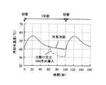
請求項7記載の発明では、室外器(42)または吸着器(51、52)への水掛け、または水素吸蔵合金(30)の保温水回路(32)への通水は、吸着式冷凍サイクル(50)で脱離過程と吸着過程とを切替える間隔の各後期部分で行うことを特徴とする。
【0025】
例えば図3に外気温度40℃で、脱離・吸着切替え後の冷却水温度の変化をグラフに示す。切替え初期は脱離・吸着量とも多いため温度が高く、徐々に温度は低下して最終的にほぼ外気温度となる。
【0026】
よって、前記燃料電池から発生する水で冷却する場合において、例えば低速走行のように車両走行に必要な電力が小さく水の発生が少ない場合には、切替え初期は外気で室外器の冷却を行い、切替え後期だけ発生水を使って蒸発冷却を行うことで、少ない冷却熱量を有効に使って最終温度を下げることができる。
【0027】
また、FCEVではアイドルが無いため停車時には発電を行わず、水も発生しない。そのため、切替え後期だけ発生水を使って蒸発冷却を行うことにより、走行時に発生した水をタンクに貯えて、停車時に使うことができる。
【0028】
これは、水掛けによる冷却だけではなく、水素吸蔵合金の保温冷水による冷却でも、切替え後期だけ保温水回路に切替えることにより、水素吸蔵合金での冷却熱量が少ない場合でも有効に最終温度を下げることができる。
【0029】
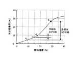
請求項8記載の発明では、吸着器(51、52)の吸着コア(51a、52a)を冷却する室外器(42)と、凝縮コア(51b、52b)を冷却する室外器(43)とを有し、燃料電池(20)で発生する水の水掛け、または水素吸蔵合金(30)の保温水回路(32)への通水は、吸着コア(51a、52a)側の室外器(42)のみに行うことを特徴とする。
【0030】
例えば図4に吸着剤の関係湿度と水分吸着率との関係をグラフに示す。関係湿度は冷却温度によって大きく変わり、水分吸着率も大きく変わるが、脱離側と吸着側では影響の度合いが異なる。
【0031】
具体的には、脱離側の冷却水温を40℃から30℃にした場合、水分吸着率はc点からa点となるが、吸着側の冷却水温を40℃から30℃にした場合、水分吸着率はd点からb点となり、吸着側を冷却した方が脱離と吸着との水分吸着率の差を容易に大きくでき、冷却性能を確保し易い。
【0032】
よって、脱離時の凝縮熱の冷却と、吸着時の吸着熱の冷却とを別々の室外器を用いて行う場合は、燃料電池からの発生水や水素吸蔵合金の保温冷水による冷却を、両方の室外器に等しく行うより、吸着コア側の室外器のみを冷却した方が、少ない冷却熱量を有効に使って吸着量を大きくすることができる。
【0033】
【発明の実施の形態】
次に、本発明を乗物として車両に用いた実施形態を、図面に基づき説明する。
【0034】
〔第1実施形態〕
図1は本発明の第1実施形態における空調装置のシステム構成を示すものであり、20はFCスタック(燃料電池と冷却手段で構成した燃料電池ユニット)であり、MHユニット(水素吸蔵合金を用いた水素貯蔵ユニット)30に貯蔵された水素と、空気中の酸素とを反応させて電気を発生させて、その電気を用いて図示しない車両駆動用モータで車両を駆動する。
【0035】
FCスタック20には、発電する際に発生する熱を冷却するための冷却水回路が設けられており、21は冷却水回路に冷却水を循環させるFC冷却ポンプである。22はFCラジエータであり、電動ファン22aで送風される車室外空気との間で熱交換して冷却水を冷却する。23はFCラジエータ22を迂回して冷却水が流れるバイパス回路である。
【0036】
24はFCスタック20から流出した冷却水を、FCラジエータ22に流す場合とバイパス回路23に流す場合とを切替える周知のサーモスタットで、このサーモスタット24内を流れる冷却水の温度に応じてFCラジエータ22とバイパス回路23とを切替えて、FCスタック20の温度が80℃程度に保たれるようFCラジエータ22への通水量を制御している。
【0037】
MHユニット30は保温水回路32で上記冷却水回路に接続されており、MHウォータバルブ31によりMHユニット30の温度が30℃程度に保たれるよう通水量を制御している。また、FCスタック20で発電する際に発生した水は水タンク61に導いて溜められ、水掛け用ポンプ62で汲み上げて水掛けノズル63から後述する吸着式冷凍器50の室外器42に吹き掛けられるようになっている。
【0038】
1は車両用空調ユニットであり、車室内計器盤下方部に搭載される。空調ユニット1の空調ケース2は、車室内に空調空気を導く空調用通路を構成しており、この空調ケース2の一端側に内気を吸入する内気吸入口4と、外気を吸入する外気吸入口5が設けられており、内外気切替ドア6により切替開閉される。
【0039】
上記吸入口4、5に隣接して、空調ケース2内に空気を送風する送風機3が設置されており、この送風機3はモータ3aとこのモータ3aにより駆動される遠心ファン3bとにより構成されている。一方、空調ケース2の他端側には車室内へ通ずる複数の吹出用開口部7、8、9が形成されている。これらの開口部7、8、9は開口部切替ドア10、11、12によりそれぞれ切替開閉される。
【0040】
また、送風機3より空気下流側における空調ケース2内には、後述する吸着式冷凍器50で作られた冷水と熱交換を行い、空気を冷却する室内器41が設けられている。さらに室内器41の空気下流側にはヒータコア13が設けられており、FCスタック20を冷却する冷却水と空気と熱交換を行い空気を加熱するものである。
【0041】
このヒータコア13の空気入口部には、ヒータコア13を通過する空気量とヒータコア13をバイパスする空気量とを調節して、車室内へ吹き出す空気の温度を調整するためのエアミックスドア14が回動自由に取付けられている。また、ヒータコア13の温水入口部にはウォータバルブ15が設置され、ヒータコア13への冷却水の通水を制御できるようになっている。
【0042】
次に、吸着式冷凍器50について、図1と図2を用いて説明する。図2は第1実施形態における吸着式冷凍サイクルの構成図である。吸着式冷凍器50は、第1、第2吸着器51、52、および流路切替弁53、54で構成される。
【0043】
第1、第2吸着器51、52は密閉容器内に、周知の熱交換器形状をなし熱交換部の周囲に多数の吸着剤を付着させた第1、第2吸着コア51a、52aと、周知の熱交換器形状をなし冷媒を蒸発・凝縮可能な第1、第2蒸発凝縮コア51b、52bを備えている。また、それぞれ密閉容器内には所定量の冷媒が封入されている。ちなみに本実施例では、吸着剤としてはシリカゲル系の吸着剤を用い、冷媒には水を用いている。
【0044】
第1、第2吸着コア51a、52aは切替弁53により温水用ウォータポンプ55を通じて前記FCスタック冷却水回路、および冷却用ウォータポンプ56を通じて室外器42の冷却水回路44に接続可能となっている。室外器42は電動ファン42aで送風される車室外空気との間で熱交換して冷却水を冷却する。また、第1、第2蒸発凝縮コア51b、52bは切替弁54により前記室外器42、および室内用ウォータポンプ57を通じて前記室内空調ユニット1内の室内器41に接続可能となっている。
【0045】
次に、上記構成による作動を説明する。まず吸着式冷凍器50の基本的な作動について説明する。吸着式冷凍器50は、第1吸着コア51aが脱離工程、第2吸着コア52aが吸着工程を行う第1工程と、第1吸着コア51aが吸着工程、第2吸着コア52aが脱離工程を行う第2工程とを所定時間(例えば100秒)毎に交互に行う。
【0046】
まず、第1工程は切替弁53、54を図2中の実線位置とすることにより行なわれる。この第1工程では、FCスタックで発電する際に加熱されたFC冷却水が温水用ウォータポンプ55により循環され、切替弁53を通って第1吸着コア51aに流入するため、第1吸着コア51aの吸着剤が加熱されて気体冷媒を脱着する。
【0047】
また、冷却用ウォータポンプ56により循環された冷却水は、切替弁54を通り第1蒸発凝縮コア51bに流入しコアを冷却する。これにより、吸着剤から脱着した気体冷媒は第1蒸発凝縮コア51bで凝縮・液化する。第1蒸発凝縮コア51bを出た冷却水は、室外器42を通り外気と熱交換を行って冷却され、再び冷却用ウォータポンプ56に戻る。
【0048】
一方、上記室外器42からの冷却水は、切替弁53を通って第2吸着コア52aにも循環するため、第2吸着コア52aの吸着剤が気体冷媒を吸着し、これにより第2吸着器52内の液体冷媒が蒸発する。そして第2蒸発凝縮コア52bでは、熱交換流体が蒸発潜熱を奪われて冷却される。
【0049】
この冷却された熱交換流体は切替弁54を通り、室内用ウォータポンプ57により室内器41に循環され、送風機3から送られた空気と熱交換を行い、空気を冷却・除湿する。室内器41を出た熱交換流体は切替弁54を通り第2蒸発凝縮コア52bに再び流入する。
【0050】
第2工程は、切替弁53、54を図2中の破線位置とすることにより行なわれる。この第2工程では、上記した第1工程の吸着と脱着、蒸発と凝縮が入れ替わるだけであるため、第2工程の作動説明は省略する。
【0051】
上記の第1工程と第2工程とを所定時間(例えば100秒)毎に交互に行うことにより、FCスタックで発生する熱を利用して冷房を行うことができる。この吸着式冷凍サイクルを用いた冷房は、コンプレッサを駆動するような動力が不要となって省動力であるのに加え、冷媒が水であるため脱フロンの観点からも、省エネルギーと環境保護を狙った燃料電池車(FCEV)に適している。
【0052】
しかし、吸着式冷凍器50は吸着剤に水を吸着する時の水の蒸発潜熱を利用して冷房を行うため、冷房能力は脱離時と吸着時の吸着剤の水分吸着率の差に比例する。図4に吸着剤の関係湿度と水分吸着率との関係をグラフに示すが、一般的に吸着剤はその種類によらず関係湿度が大きいほど水分吸着率が大きくなる。関係湿度とは吸着剤が存在する雰囲気の水蒸気分圧P1と、吸着剤の湿度における飽和水蒸気分圧P2との比(P1/P2)である。
【0053】
本実施形態のように密閉系の場合は、吸着器内の蒸気圧力P1と吸着剤温度における飽和水蒸気圧力P2との比となり、脱離側の吸着器51では、吸着器内の蒸気圧力は凝縮温度、すなわち室外器42からの冷却水温度の飽和圧力となり、吸着剤温度はFCスタックからの温水温度となる。また、吸着側の吸着器52では、吸着器内の蒸気圧力は蒸発温度の飽和圧力となり、吸着剤温度は室外器42からの冷却水温度となる。
【0054】
FCEVの場合、FCスタックの温水温度はサーモスタット24により例えば80℃に制御されており、また、蒸発温度は車両用の空調装置としての冷房感から10℃程度が必要となる。よって、関係湿度は室外器42からの冷却水温度によって決まる。図4に示すように、冷却水温度30℃における脱離はa点、吸着はb点となり、水分吸着率の差が大きく冷房能力が大きいのに対し、冷却水温度が40℃では、脱離はc点、吸着はd点となり、水分吸着率の差が小さく冷房能力が小さくなる。
【0055】
次に、本実施形態の特徴を説明する。FCスタックで発電する際には熱と一緒に水が発生する。その量は、理論的には電気出力1kwで1時間当たり470gであり、車両走行に例えば10kw電気が必要な場合には4.7kgの水が毎時発生する。
【0056】
その発生した水をタンク61に蓄えて、水掛け用ポンプ62で汲み上げて、水掛けノズル63から前記室外器42に掛けるようにすることで、水は室外器42の表面で蒸発し、その蒸発潜熱で室外器42の中を流れる冷却水を冷却する。
【0057】
水の蒸発潜熱は、約2400kJ/kgであるため3kw以上の冷却熱量となり、蒸発温度は外気温度40℃、湿度35%時において27度となる。その結果、外気温度40℃においても、室外器42からの冷却水温度を30℃程度とすることができ、冷房能力が低下するのを防止できる。
【0058】
これにより、吸着式エアコンを車両用に適用する上で大きな問題となる高外気温時の著しい冷房能力の低下を、本発明ではFCEV特有のFCスタック20からの発生水を利用し、室外器42に掛けて蒸発冷却することによって解決している。
【0059】
この冷却方法は、特別な冷却水回路を必要とせず、上記の簡単な水掛け装置を加えるだけで実現できるため、実施容易である。ちなみに、蒸発冷却は上記のように室外器42の表面に水掛けして行っても良いし、室外器42の空気上流に噴霧して蒸発冷却した空気を室外器42に送風しても良い。
【0060】
〔第2実施形態〕
図5に本発明の第2実施形態における吸着器51、52の構成図を示す。FCスタック20からの発生水を利用して蒸発冷却する構造は、図5に示すように吸着式冷凍器50の吸着器51、52本体に冷却フィン51c等を配置して放熱を良くして、そこへ直接FCスタック20で発生した水を前記の水掛けノズル63から吹き掛けて蒸発冷却させても良い。
【0061】
但しこの場合、吸着過程にある側の吸着器にだけ水掛けを行うこととなる。またこの冷却は、例えば室外器42との間の冷却水配管の一部を放熱の良い形状として、その配管部分に水掛けを行っても良い。
【0062】
〔第3実施形態〕
図6に本発明の第3実施形態における空調装置の全体構成図を示す。吸着式冷凍器50の冷却水回路を除き、図1に示した第1実施形態のシステムと同じである。
【0063】
吸着式冷凍器50の冷却水回路は、切替弁71〜74により室外器42とMHユニット30とのどちらかに接続可能な構成となっている。切替弁71〜74を図6に示す実線位置とすることで、吸着式冷凍器50の冷却水回路はMHユニット30に接続され、室外器42は切り離される。また、切替弁71〜74を図6に示す破線位置とすることで、吸着式冷凍器50の冷却水回路は室外器42に接続され、MHユニット30はFCスタック20の冷却水回路に接続される。
【0064】
次に、作動と効果を説明する。FCスタック20で発電する際に必要となる水素は、MHユニット30の水素吸蔵合金に貯蔵されている水素が用いられる。水素を取り出すには水素放出用の熱を水素吸蔵合金に与えて、水素吸蔵合金を約30℃に保つ必要がある。通常この熱は、FCスタック20で発生する熱を冷却する冷却水回路から得ている。
【0065】
その熱量は、FCスタック20での発電電力1kw当り約0.2kwの熱量が必要となり、車両走行に例えば10kwの電気が必要な場合には2kwの水素放出熱が必要となる。逆に言えばMHユニット30に送られた冷却水は2kw冷却されることとなる。
【0066】
本実施形態では、吸着式冷凍器50の冷却水回路を、外気と熱交換する室外器42ではなく、MHユニット30に接続可能とすることで、外気温度に依存せず吸着式冷凍器50を冷却することが可能となる。
【0067】
これにより、外気温度が40℃であるような高外気温時においても、外気温度に依存せず吸着式冷凍器50を30℃程度で冷却することができるため、冷房能力の低下を防止することができる。また、本実施形態は冷却水路の切替えだけで容易に実施可能となる。
【0068】
〔第4実施形態〕
図7に第4実施形態における吸着式冷凍サイクルの構成図を示す。前記実施形態では吸着式冷凍器50における脱離時の凝縮熱の冷却と吸着時の吸着熱の冷却とを、同じ冷却水回路44(同じ室外器42)を用いて行っているが、図7に示すようにそれぞれを別々の室外器42、43(と別々の冷却用ウォータポンプ56、58)を用いて冷却を行っても良い。
【0069】
この場合には図示していないが、前記のFCスタック20からの発生水やMHユニット30の保温冷水による冷却を、両方の室外器42、43に等しく行うより、吸着コア51a、52aを冷却する側の室外器42に用いた方が良い。
【0070】
図4に吸着剤の関係湿度と水分吸着率との関係をグラフに示すが、理由はこの図に示すように脱離側の冷却よりも吸着側の冷却の方が水分吸着率の差に大きく影響するためである。
【0071】
具体的には、脱離側の冷却水温を40℃から30℃にした場合、水分吸着率はc点からa点となるが、吸着側の冷却水温を40℃から30℃にした場合、水分吸着率はd点からb点となり、吸着側を冷却した方が脱離と吸着との水分吸着率の差を容易に大きくでき、冷却性能を確保し易い。
【0072】
よって、脱離時の凝縮熱の冷却と、吸着時の吸着熱の冷却とを別々の室外器を用いて行う場合は、FCスタック20からの発生水やMHユニット30の保温冷水による冷却は吸着コア側の室外器のみにした方が、少ない冷却熱量を有効に使って吸着量を大きくすることができる。これは、吸着器51、52や冷却水配管に水掛けして冷却する場合も吸着コア側(吸着過程側)を行うのが良い。
【0073】
上述下各実施形態では乗物として車両に燃料電池を搭載した例を説明したが、燃料電池を動力源とする乗物であって空調装置を組合せるものであれば、軌道車両、船舶等の他の乗物にも本発明を適用できる。
【図面の簡単な説明】
【図1】本発明の第1実施形態における空調装置の全体構成図である。
【図2】第1実施形態における吸着式冷凍サイクルの構成図である。
【図3】外気温度40℃で、脱離・吸着切替え後の冷却水温度の変化を示すグラフである。
【図4】吸着剤の関係湿度と水分吸着率との関係を示すグラフである。
【図5】本発明の第2実施形態における吸着器の構成図である。
【図6】本発明の第3実施形態における空調装置の全体構成図である。
【図7】第4実施形態における吸着式冷凍サイクルの構成図である。
【符号の説明】
1 空調装置
20 FCスタック(燃料電池)
30 MHユニット(水素吸蔵合金)
32 保温水回路
42、43 室外器
44 冷却水回路
50 吸着式冷凍サイクル
51、52 吸着器
51a、52a 吸着コア
51b、52b 凝縮コア[0001]
BACKGROUND OF THE INVENTION
The present invention relates to a vehicle air conditioner that can be applied to a vehicle equipped with a fuel cell, for example, a vehicle driven by power generated by the fuel cell, a rail vehicle, a ship, and the like, and particularly a vehicle using an adsorption refrigeration cycle. The present invention relates to an air conditioner for automobiles.
[0002]
[Prior art]
In recent years, a fuel cell vehicle (hereinafter referred to as FCEV) driven by electric power generated by a fuel cell (FC stack) as an eco car has attracted attention as a future automobile from the viewpoint of energy saving and environmental protection. A fuel cell reacts hydrogen and oxygen in the air to generate electricity, water, and reaction heat. Therefore, FCEV is a completely clean vehicle that does not generate any exhaust gas.
[0003]
As an air conditioner for FCEV, an apparatus in which a compressor is electrically driven using a vapor compression refrigeration cycle generally used in a vehicle driven by a conventional internal combustion engine has been proposed.
[0004]
[Problems to be solved by the invention]
However, the vapor compression refrigeration cycle requires electric power for the compressor power and uses chlorofluorocarbon as a refrigerant. Therefore, it cannot be said that the vapor compression refrigeration cycle is suitable for use in an FCEV air conditioner aiming at energy saving and environmental protection.
[0005]
The present invention has been made in view of the above prior art, and an object thereof is to provide a vehicle air conditioner suitable for a vehicle including an FCEV equipped with a fuel cell from the viewpoint of energy saving and environmental protection. .
[0006]
[Means for Solving the Problems]
In order to achieve the above object, according to the first aspect of the present invention, when an adsorption refrigeration cycle (50) is usedin a vehicle air conditioner (1) on which a fuel cell (20) is mountedand the fuel cell (20) generates power. The water generated in is used for cooling the adsorption refrigeration cycle (50) .
[0007]
This uses the reaction heat generated when the fuel cell generates power to drive the adsorption refrigeration cycle. In the adsorption refrigeration cycle, water as a refrigerant is adsorbed to a dried adsorbent (adsorption process), and cooling is performed by the latent heat of vaporization of the water at that time. Water is desorbed by heating the adsorbent ( Desorption process), allowing adsorption again.
[0008]
By using reaction heat in the fuel cell to heat the adsorbent, power to drive the compressor is unnecessary and power is saved. Therefore, it is suitable for vehicles equipped with fuel cells for energy saving and environmental protection.
[0010]
Furthermore , when an adsorption refrigeration cycle is applied to a vehicle, generally the cooling of the adsorption heat of the adsorbent generated during the adsorption process and the cooling of the condensation heat of the adsorbent generated during the desorption process are performed in an outdoor unit. Since it is conducted through brine (heat exchange fluid) that exchanges heat with the outside air, the higher the outside air temperature, the higher the cooling temperature, and the difference in moisture adsorption rate between adsorption and desorption with the adsorbent becomes small. There is a problem that the cooling capacity is lowered.
[0011]
In particular, when the outside air temperature exceeds 30 ° C., the cooling capacity is remarkably lowered, which is a serious problem when applied to a vehicle air conditioner. As a countermeasure, by using the water generated when generating electricity with a previously discarded fuel cell for cooling the adsorption refrigeration cycle, it can be cooled below the outside temperature with the latent heat of water evaporation even at high outside temperatures, It is possible to prevent the cooling capacity from being lowered.
[0012]
The invention according to
[0013]
Specifically, water generated when generating electricity with the fuel cell is stored in a tank, pumped up by a pump, and sprayed from the nozzle to the outdoor unit of the adsorption refrigeration cycle. Thereby, the sprayed water evaporates on the outdoor unit surface, and the cooling water flowing through the outdoor unit can be cooled by the latent heat of evaporation. In addition, this cooling method is easy to implement because it does not require a special cooling water circuit and can be realized only by adding the above simple watering device.
[0014]
The invention according to claim3 is characterized in that the water generated when generating electricity in the fuel cell (20) is cooled by watering the adsorbers (51, 52) of the adsorption refrigeration cycle (50). To do.
[0015]
This corresponds to another embodiment with respect to the previous section. Specifically, when a cooling fin or the like is arranged in the adsorber body of the adsorption refrigeration cycle to improve heat dissipation, and when power is generated by the fuel cell there The generated water is sprayed with the above-mentioned watering device or the like.
[0016]
Thereby, the sprayed water evaporates on the surface of the adsorber body, and the adsorber itself can be cooled by the latent heat of evaporation. Also, this cooling method is easy to implement because it does not require a special cooling water circuit and can be realized simply by adding the above-described simple watering device.
[0017]
The invention according to claim4 is characterized in that a hydrogen storage alloy (30) is used as a hydrogen source when generating power in the fuel cell (20).
[0018]
As in thefirst aspect, the adsorption refrigeration cycle is cooled by something other than outside air at high outside air temperature. There are several methods for supplying hydrogen required when generating power with a fuel cell. However, by using a hydrogen storage alloy as the supply source, the hydrogen release endotherm generated when hydrogen is taken out can be used.
[0019]
The invention according to claim5 is characterized in that the hot water of the hydrogen storage alloy (30) is used for cooling the adsorption refrigeration cycle (50).
[0020]
In order to take out the hydrogen stored in the hydrogen storage alloy, it is necessary to give the hydrogen storage heat to the hydrogen storage alloy and keep it at about 30 ° C. Therefore, the hydrogen storage alloy thermal insulation water circuit is connected to the fuel cell cooling circuit, and a portion of the fuel cell cooling hot water (approximately 80 ° C.) is taken in and balanced with the cooling by the hydrogen release endotherm generated by the hydrogen storage alloy. And kept at about 30 ° C.
[0021]
By using this heat retaining water of about 30 ° C. for cooling of the adsorption refrigeration cycle, it is possible to cool about 30 ° C. without depending on the outside air temperature even at a high outside air temperature of 30 ° C. or more. Can be prevented.
[0022]
In invention of Claim6, the cooling water circuit (44) which used the outdoor unit (42) for the cooling water circuit of an adsorption-type refrigeration cycle (50), and the heat retention water for heat-retaining a hydrogen storage alloy (30) It is characterized in that both the circuit (32) and the circuit (32) can be connected and switched.
[0023]
As a result, the adsorption refrigeration cycle can be easily cooled only by switching the water channel with the cold storage water of the hydrogen storage alloy at a high outside air temperature.
[0024]
According to theseventh aspect of the present invention, the watering to the outdoor unit (42) or the adsorber (51, 52) or thewater passing through the heat storage water circuit (32) of the hydrogen storage alloy (30) is performed by an adsorption refrigeration cycle. (50), characterized in that it is performed at each latter part of the interval for switching between the desorption process and the adsorption process.
[0025]
For example, FIG. 3 is a graph showing changes in cooling water temperature after desorption / adsorption switching at an outside air temperature of 40 ° C. Since the amount of desorption / adsorption is large at the initial stage of switching, the temperature is high, the temperature gradually decreases, and finally becomes almost the outside temperature.
[0026]
Therefore, in the case of cooling with water generated from the fuel cell, for example, when the power required for vehicle travel is small and the generation of water is low, such as at low speeds, the outdoor unit is cooled with outside air at the beginning of switching, By performing evaporative cooling using the generated water only in the latter half of the switching, the final temperature can be lowered by effectively using a small amount of cooling heat.
[0027]
In addition, since there is no idle in FCEV, no power is generated when the vehicle is stopped, and no water is generated. Therefore, by performing evaporative cooling using the generated water only in the late stage of switching, the water generated during traveling can be stored in the tank and used when the vehicle is stopped.
[0028]
This is not only by cooling by watering, but also by cooling the hydrogen storage alloy with cold insulation water, by switching to the heat insulation water circuit only during the latter period of switching, the final temperature can be effectively lowered even when the amount of cooling heat in the hydrogen storage alloy is small. Can do.
[0029]
In the invention according to
[0030]
For example, FIG. 4 is a graph showing the relationship between the relative humidity of the adsorbent and the moisture adsorption rate. The relative humidity varies greatly depending on the cooling temperature, and the moisture adsorption rate also varies greatly. However, the degree of influence differs between the desorption side and the adsorption side.
[0031]
Specifically, when the cooling water temperature on the desorption side is changed from 40 ° C. to 30 ° C., the moisture adsorption rate is changed from the point c to the point a, but when the cooling water temperature on the adsorption side is changed from 40 ° C. to 30 ° C. The adsorption rate is changed from point d to point b, and cooling the adsorption side can easily increase the difference in moisture adsorption rate between desorption and adsorption, so that the cooling performance can be easily ensured.
[0032]
Therefore, when cooling the condensation heat at the time of desorption and cooling of the adsorption heat at the time of adsorption using separate outdoor units, both cooling with the water generated from the fuel cell and the cold storage water of the hydrogen storage alloy is required. It is possible to increase the amount of adsorption by effectively using a small amount of cooling heat when only the outdoor unit on the adsorption core side is cooled rather than performing the same on the outdoor unit.
[0033]
DETAILED DESCRIPTION OF THE INVENTION
Next, an embodiment in which the present invention is used for a vehicle as a vehicle will be described with reference to the drawings.
[0034]
[First Embodiment]
FIG. 1 shows a system configuration of an air conditioner according to a first embodiment of the present invention.
[0035]
The
[0036]
[0037]
The
[0038]
[0039]
A blower 3 for blowing air is installed in the
[0040]
Further, an
[0041]
An
[0042]
Next, the
[0043]
The first and
[0044]
The first and
[0045]
Next, the operation according to the above configuration will be described. First, the basic operation of the
[0046]
First, the first step is performed by setting the switching
[0047]
The cooling water circulated by the cooling
[0048]
On the other hand, since the cooling water from the
[0049]
The cooled heat exchange fluid passes through the switching
[0050]
The second step is performed by setting the switching
[0051]
By alternately performing the first step and the second step every predetermined time (for example, 100 seconds), cooling can be performed using the heat generated in the FC stack. Cooling using this adsorption refrigeration cycle not only requires power to drive the compressor, but also saves power. In addition, since the refrigerant is water, it aims to save energy and protect the environment from the standpoint of removing chlorofluorocarbons. Suitable for fuel cell vehicles (FCEV).
[0052]
However, since the
[0053]
In the case of a closed system as in this embodiment, the ratio is the ratio of the vapor pressure P1 in the adsorber to the saturated water vapor pressure P2 at the adsorbent temperature. In the
[0054]
In the case of FCEV, the hot water temperature of the FC stack is controlled to, for example, 80 ° C. by the
[0055]
Next, features of the present embodiment will be described. When generating electricity with the FC stack, water is generated along with heat. The amount is theoretically 470 g per hour at an electrical output of 1 kw, and 4.7 kg of water is generated every hour when, for example, 10 kw electricity is required for vehicle travel.
[0056]
The generated water is stored in the
[0057]
Since the latent heat of vaporization of water is about 2400 kJ / kg, the amount of cooling heat is 3 kw or more, and the evaporation temperature is 27 degrees at an outside air temperature of 40 ° C. and a humidity of 35%. As a result, even at an outside air temperature of 40 ° C., the temperature of the cooling water from the
[0058]
As a result, in the present invention, by using the water generated from the FC stack 20 unique to the FCEV, a significant decrease in cooling capacity at a high outside air temperature, which is a major problem in applying the adsorption type air conditioner for vehicles, the
[0059]
This cooling method is easy to implement because it does not require a special cooling water circuit and can be realized simply by adding the above-described simple watering device. Incidentally, the evaporative cooling may be performed by watering the surface of the
[0060]
[Second Embodiment]
FIG. 5 shows a configuration diagram of the
[0061]
However, in this case, only the adsorber on the side in the adsorption process is watered. In addition, for this cooling, for example, a part of the cooling water pipe between the
[0062]
[Third Embodiment]
FIG. 6 shows an overall configuration diagram of an air conditioner according to a third embodiment of the present invention. Except for the cooling water circuit of the
[0063]
The cooling water circuit of the
[0064]
Next, the operation and effect will be described. Hydrogen stored in the hydrogen storage alloy of the
[0065]
The amount of heat required is about 0.2 kW per 1 kW of power generated by the
[0066]
In the present embodiment, the cooling water circuit of the
[0067]
Thereby, even at the time of a high outside air temperature where the outside air temperature is 40 ° C., the
[0068]
[Fourth Embodiment]
FIG. 7 shows a configuration diagram of an adsorption refrigeration cycle in the fourth embodiment. In the above embodiment, the cooling of the condensation heat at the time of desorption and the cooling of the adsorption heat at the time of adsorption in the
[0069]
In this case, although not shown, the
[0070]
FIG. 4 is a graph showing the relationship between the relative humidity of the adsorbent and the moisture adsorption rate. The reason is that the adsorption side cooling is larger in the moisture adsorption rate difference than the desorption side cooling as shown in FIG. It is because it affects.
[0071]
Specifically, when the cooling water temperature on the desorption side is changed from 40 ° C. to 30 ° C., the moisture adsorption rate is changed from the point c to the point a, but when the cooling water temperature on the adsorption side is changed from 40 ° C. to 30 ° C. The adsorption rate is changed from the point d to the point b, and cooling the adsorption side can easily increase the difference in moisture adsorption rate between desorption and adsorption, so that the cooling performance can be easily ensured.
[0072]
Therefore, when cooling of the condensation heat at the time of desorption and cooling of the adsorption heat at the time of adsorption are performed using separate outdoor units, the cooling by the generated water from the
[0073]
In each of the embodiments described above, an example in which a fuel cell is mounted on a vehicle as a vehicle has been described. However, as long as the vehicle uses a fuel cell as a power source and is combined with an air conditioner, other vehicles such as track vehicles and ships The present invention can also be applied to vehicles.
[Brief description of the drawings]
FIG. 1 is an overall configuration diagram of an air conditioner according to a first embodiment of the present invention.
FIG. 2 is a configuration diagram of an adsorption refrigeration cycle in the first embodiment.
FIG. 3 is a graph showing changes in cooling water temperature after desorption / adsorption switching at an outside air temperature of 40 ° C.
FIG. 4 is a graph showing the relationship between the relative humidity of the adsorbent and the moisture adsorption rate.
FIG. 5 is a configuration diagram of an adsorber according to a second embodiment of the present invention.
FIG. 6 is an overall configuration diagram of an air conditioner according to a third embodiment of the present invention.
FIG. 7 is a configuration diagram of an adsorption refrigeration cycle in a fourth embodiment.
[Explanation of symbols]
1
30 MH unit (hydrogen storage alloy)
32 Thermal
Claims (8)
Translated fromJapanesePriority Applications (1)
| Application Number | Priority Date | Filing Date | Title |
|---|---|---|---|
| JP2000029260AJP4265067B2 (en) | 2000-02-07 | 2000-02-07 | Vehicle air conditioner |
Applications Claiming Priority (1)
| Application Number | Priority Date | Filing Date | Title |
|---|---|---|---|
| JP2000029260AJP4265067B2 (en) | 2000-02-07 | 2000-02-07 | Vehicle air conditioner |
Publications (2)
| Publication Number | Publication Date |
|---|---|
| JP2001213149A JP2001213149A (en) | 2001-08-07 |
| JP4265067B2true JP4265067B2 (en) | 2009-05-20 |
Family
ID=18554547
Family Applications (1)
| Application Number | Title | Priority Date | Filing Date |
|---|---|---|---|
| JP2000029260AExpired - Fee RelatedJP4265067B2 (en) | 2000-02-07 | 2000-02-07 | Vehicle air conditioner |
Country Status (1)
| Country | Link |
|---|---|
| JP (1) | JP4265067B2 (en) |
Cited By (1)
| Publication number | Priority date | Publication date | Assignee | Title |
|---|---|---|---|---|
| US20170144508A1 (en)* | 2015-11-20 | 2017-05-25 | Toyota Jidosha Kabushiki Kaisha | Vehicular adsorption type air conditioning device |
Families Citing this family (12)
| Publication number | Priority date | Publication date | Assignee | Title |
|---|---|---|---|---|
| JP4380312B2 (en)* | 2003-12-11 | 2009-12-09 | Jfeエンジニアリング株式会社 | Air conditioner for moving body |
| JP4281564B2 (en) | 2004-02-02 | 2009-06-17 | 株式会社デンソー | Air conditioner for vehicles |
| CN102121734B (en)* | 2009-11-04 | 2014-03-19 | 合肥博普高新科技有限公司 | Small energy-saving environment-friendly refrigerating air conditioner |
| JP5614611B2 (en)* | 2009-11-09 | 2014-10-29 | 剛正 山田 | Electric mobile body comprising a secondary battery and a solid oxide fuel cell |
| DE102015004524A1 (en)* | 2014-12-11 | 2016-06-16 | Sortech Ag | Method and device for cyclically operating a thermoelectric cell arrangement |
| CN104613575A (en)* | 2014-12-23 | 2015-05-13 | 深圳市沃森空调技术有限公司 | Automotive air-conditioner with hydrogen fuel cell |
| EP3247948B1 (en)* | 2015-01-08 | 2024-05-01 | Bry-Air (Asia) Pvt. Ltd. | Split type adsorption air conditioning unit |
| JP6515784B2 (en)* | 2015-10-23 | 2019-05-22 | トヨタ自動車株式会社 | Vehicle cooling system |
| JP6319275B2 (en) | 2015-11-20 | 2018-05-09 | トヨタ自動車株式会社 | Vehicle air conditioner equipped with adsorption heat pump |
| WO2019069598A1 (en)* | 2017-10-06 | 2019-04-11 | 株式会社デンソー | Adsorber and adsorption-type refrigerator |
| JP2019070509A (en)* | 2017-10-06 | 2019-05-09 | 株式会社デンソー | Adsorber and adsorptive refrigeration machine |
| IT201900003829A1 (en)* | 2019-03-15 | 2020-09-15 | Marelli Europe Spa | ADSORPTION REFRIGERATOR SYSTEM FOR THE PRODUCTION OF DEMINERALIZED WATER ON BOARD A MOTOR VEHICLE, MOTOR VEHICLE AND METHOD OF PRODUCTION OF DEMINERALIZED WATER ON BOARD A MOTOR VEHICLE |
- 2000
- 2000-02-07JPJP2000029260Apatent/JP4265067B2/ennot_activeExpired - Fee Related
Cited By (2)
| Publication number | Priority date | Publication date | Assignee | Title |
|---|---|---|---|---|
| US20170144508A1 (en)* | 2015-11-20 | 2017-05-25 | Toyota Jidosha Kabushiki Kaisha | Vehicular adsorption type air conditioning device |
| US10137762B2 (en)* | 2015-11-20 | 2018-11-27 | Toyota Jidosha Kabushiki Kaisha | Vehicular adsorption type air conditioning device |
Also Published As
| Publication number | Publication date |
|---|---|
| JP2001213149A (en) | 2001-08-07 |
Similar Documents
| Publication | Publication Date | Title |
|---|---|---|
| US9610825B2 (en) | Motor vehicle climate control system | |
| JP4265067B2 (en) | Vehicle air conditioner | |
| JP2005212735A (en) | Air conditioner for vehicle | |
| JP2007069733A (en) | Heating element cooling system using air conditioner for vehicle | |
| JP6562004B2 (en) | Vehicle air conditioner equipped with adsorption heat pump | |
| JP2024178706A (en) | Vehicle Air Conditioning System | |
| JP2009154862A (en) | Electric vehicle air conditioning system | |
| JPH05155236A (en) | Air-conditioning device for electric automobile | |
| JP3959829B2 (en) | Refrigeration equipment and air conditioning equipment | |
| JP2000289451A (en) | Air conditioning system for vehicle | |
| JPH1163719A (en) | Freezer device | |
| JP4341090B2 (en) | Adsorption refrigerator for vehicles | |
| JP2955899B2 (en) | Automotive air conditioners | |
| KR101651981B1 (en) | Absorption type air conditioning system for automotive vehicles | |
| JP4341091B2 (en) | Adsorption air conditioner for vehicles | |
| JP4158235B2 (en) | Air conditioner for vehicles | |
| JP4186339B2 (en) | Adsorption type refrigerator | |
| JP4069691B2 (en) | Air conditioner for vehicles | |
| JP4082192B2 (en) | Air conditioner | |
| JPH06206439A (en) | Heat pump type air-conditioning device for vehicle | |
| JP2004284432A (en) | Vehicular adsorption type air-conditioner | |
| JP2002178742A (en) | Adsorption type refrigerator for vehicle | |
| RU2562003C2 (en) | Automotive climate control system and method of its operation | |
| JP2018071923A (en) | Vehicle air conditioner equipped with adsorption heat pump | |
| JP2018070038A (en) | Vehicle air conditioner equipped with adsorption heat pump |
Legal Events
| Date | Code | Title | Description |
|---|---|---|---|
| A621 | Written request for application examination | Free format text:JAPANESE INTERMEDIATE CODE: A621 Effective date:20060417 | |
| RD01 | Notification of change of attorney | Free format text:JAPANESE INTERMEDIATE CODE: A7421 Effective date:20060524 | |
| A977 | Report on retrieval | Free format text:JAPANESE INTERMEDIATE CODE: A971007 Effective date:20081017 | |
| A131 | Notification of reasons for refusal | Free format text:JAPANESE INTERMEDIATE CODE: A131 Effective date:20081028 | |
| A521 | Written amendment | Free format text:JAPANESE INTERMEDIATE CODE: A523 Effective date:20081223 | |
| TRDD | Decision of grant or rejection written | ||
| A01 | Written decision to grant a patent or to grant a registration (utility model) | Free format text:JAPANESE INTERMEDIATE CODE: A01 Effective date:20090127 | |
| A01 | Written decision to grant a patent or to grant a registration (utility model) | Free format text:JAPANESE INTERMEDIATE CODE: A01 | |
| A61 | First payment of annual fees (during grant procedure) | Free format text:JAPANESE INTERMEDIATE CODE: A61 Effective date:20090209 | |
| R150 | Certificate of patent or registration of utility model | Free format text:JAPANESE INTERMEDIATE CODE: R150 | |
| FPAY | Renewal fee payment (event date is renewal date of database) | Free format text:PAYMENT UNTIL: 20120227 Year of fee payment:3 | |
| FPAY | Renewal fee payment (event date is renewal date of database) | Free format text:PAYMENT UNTIL: 20130227 Year of fee payment:4 | |
| FPAY | Renewal fee payment (event date is renewal date of database) | Free format text:PAYMENT UNTIL: 20140227 Year of fee payment:5 | |
| R250 | Receipt of annual fees | Free format text:JAPANESE INTERMEDIATE CODE: R250 | |
| LAPS | Cancellation because of no payment of annual fees |