JP4264001B2 - Quality of service execution in the storage network - Google Patents
Quality of service execution in the storage networkDownload PDFInfo
- Publication number
- JP4264001B2 JP4264001B2JP2003538922AJP2003538922AJP4264001B2JP 4264001 B2JP4264001 B2JP 4264001B2JP 2003538922 AJP2003538922 AJP 2003538922AJP 2003538922 AJP2003538922 AJP 2003538922AJP 4264001 B2JP4264001 B2JP 4264001B2
- Authority
- JP
- Japan
- Prior art keywords
- initiator
- switch
- storage
- requests
- bandwidth
- Prior art date
- Legal status (The legal status is an assumption and is not a legal conclusion. Google has not performed a legal analysis and makes no representation as to the accuracy of the status listed.)
- Expired - Lifetime
Links
- 239000003999initiatorSubstances0.000claimsdescription181
- 238000000034methodMethods0.000claimsdescription35
- 239000000872bufferSubstances0.000claimsdescription22
- 238000004891communicationMethods0.000claimsdescription9
- 230000005540biological transmissionEffects0.000claimsdescription4
- 238000012544monitoring processMethods0.000claims2
- 238000007726management methodMethods0.000description26
- 238000012546transferMethods0.000description23
- 239000004744fabricSubstances0.000description22
- 238000010586diagramMethods0.000description20
- 230000006870functionEffects0.000description19
- 230000004044responseEffects0.000description19
- 239000000835fiberSubstances0.000description17
- 238000012545processingMethods0.000description10
- 230000008569processEffects0.000description9
- BASFCYQUMIYNBI-UHFFFAOYSA-NplatinumChemical compound[Pt]BASFCYQUMIYNBI-UHFFFAOYSA-N0.000description6
- 238000013519translationMethods0.000description6
- 230000009471actionEffects0.000description4
- 229920000638styrene acrylonitrilePolymers0.000description4
- 229910052697platinumInorganic materials0.000description3
- BQCADISMDOOEFD-UHFFFAOYSA-NSilverChemical compound[Ag]BQCADISMDOOEFD-UHFFFAOYSA-N0.000description2
- 230000002776aggregationEffects0.000description2
- 238000004220aggregationMethods0.000description2
- 230000008901benefitEffects0.000description2
- 238000013500data storageMethods0.000description2
- PCHJSUWPFVWCPO-UHFFFAOYSA-NgoldChemical compound[Au]PCHJSUWPFVWCPO-UHFFFAOYSA-N0.000description2
- 229910052737goldInorganic materials0.000description2
- 239000010931goldSubstances0.000description2
- RGNPBRKPHBKNKX-UHFFFAOYSA-NhexaflumuronChemical compoundC1=C(Cl)C(OC(F)(F)C(F)F)=C(Cl)C=C1NC(=O)NC(=O)C1=C(F)C=CC=C1FRGNPBRKPHBKNKX-UHFFFAOYSA-N0.000description2
- 238000011176poolingMethods0.000description2
- 229910052709silverInorganic materials0.000description2
- 239000004332silverSubstances0.000description2
- 230000003068static effectEffects0.000description2
- 229910000906BronzeInorganic materials0.000description1
- 102100035233FurinHuman genes0.000description1
- 108090001126FurinProteins0.000description1
- 101000860173Myxococcus xanthus C-factorProteins0.000description1
- 241001195377ProratesSpecies0.000description1
- 238000009825accumulationMethods0.000description1
- 238000007792additionMethods0.000description1
- 238000003491arrayMethods0.000description1
- 239000010974bronzeSubstances0.000description1
- 230000008859changeEffects0.000description1
- 238000006243chemical reactionMethods0.000description1
- 238000010276constructionMethods0.000description1
- KUNSUQLRTQLHQQ-UHFFFAOYSA-Ncopper tinChemical compound[Cu].[Sn]KUNSUQLRTQLHQQ-UHFFFAOYSA-N0.000description1
- 230000007423decreaseEffects0.000description1
- 230000004069differentiationEffects0.000description1
- 238000009434installationMethods0.000description1
- 239000012464large bufferSubstances0.000description1
- 238000013507mappingMethods0.000description1
- 238000012986modificationMethods0.000description1
- 230000004048modificationEffects0.000description1
- 230000003287optical effectEffects0.000description1
- 229920000915polyvinyl chloridePolymers0.000description1
- 230000010076replicationEffects0.000description1
- 230000001360synchronised effectEffects0.000description1
- 238000012360testing methodMethods0.000description1
- 230000003442weekly effectEffects0.000description1
Images


Classifications
- H—ELECTRICITY
- H04—ELECTRIC COMMUNICATION TECHNIQUE
- H04L—TRANSMISSION OF DIGITAL INFORMATION, e.g. TELEGRAPHIC COMMUNICATION
- H04L67/00—Network arrangements or protocols for supporting network services or applications
- H04L67/01—Protocols
- H04L67/10—Protocols in which an application is distributed across nodes in the network
- H04L67/1097—Protocols in which an application is distributed across nodes in the network for distributed storage of data in networks, e.g. transport arrangements for network file system [NFS], storage area networks [SAN] or network attached storage [NAS]
- H—ELECTRICITY
- H04—ELECTRIC COMMUNICATION TECHNIQUE
- H04L—TRANSMISSION OF DIGITAL INFORMATION, e.g. TELEGRAPHIC COMMUNICATION
- H04L67/00—Network arrangements or protocols for supporting network services or applications
- H04L67/01—Protocols
- H04L67/10—Protocols in which an application is distributed across nodes in the network
- H04L67/1001—Protocols in which an application is distributed across nodes in the network for accessing one among a plurality of replicated servers
- H04L67/1004—Server selection for load balancing
- H04L67/1008—Server selection for load balancing based on parameters of servers, e.g. available memory or workload
- H—ELECTRICITY
- H04—ELECTRIC COMMUNICATION TECHNIQUE
- H04L—TRANSMISSION OF DIGITAL INFORMATION, e.g. TELEGRAPHIC COMMUNICATION
- H04L67/00—Network arrangements or protocols for supporting network services or applications
- H04L67/01—Protocols
- H04L67/10—Protocols in which an application is distributed across nodes in the network
- H04L67/1001—Protocols in which an application is distributed across nodes in the network for accessing one among a plurality of replicated servers
- H04L67/1004—Server selection for load balancing
- H04L67/101—Server selection for load balancing based on network conditions
- H—ELECTRICITY
- H04—ELECTRIC COMMUNICATION TECHNIQUE
- H04L—TRANSMISSION OF DIGITAL INFORMATION, e.g. TELEGRAPHIC COMMUNICATION
- H04L67/00—Network arrangements or protocols for supporting network services or applications
- H04L67/50—Network services
- H04L67/60—Scheduling or organising the servicing of application requests, e.g. requests for application data transmissions using the analysis and optimisation of the required network resources
- H04L67/61—Scheduling or organising the servicing of application requests, e.g. requests for application data transmissions using the analysis and optimisation of the required network resources taking into account QoS or priority requirements
- H—ELECTRICITY
- H04—ELECTRIC COMMUNICATION TECHNIQUE
- H04L—TRANSMISSION OF DIGITAL INFORMATION, e.g. TELEGRAPHIC COMMUNICATION
- H04L67/00—Network arrangements or protocols for supporting network services or applications
- H04L67/01—Protocols
- H04L67/10—Protocols in which an application is distributed across nodes in the network
- H04L67/1001—Protocols in which an application is distributed across nodes in the network for accessing one among a plurality of replicated servers
Landscapes
- Engineering & Computer Science (AREA)
- Computer Networks & Wireless Communication (AREA)
- Signal Processing (AREA)
- Computer Hardware Design (AREA)
- General Engineering & Computer Science (AREA)
- Data Exchanges In Wide-Area Networks (AREA)
Description
Translated fromJapanese関連出願
本願は、2001年9月28日出願の米国仮出願シリアル番号第60/325,704号、「記憶エリア・ネットワークのための記憶スイッチ」の優先権を主張する。ここに参照により組み込む。Related Application Thisapplication claims priority to US Provisional Application Serial No. 60 / 325,704, filed September 28, 2001, “Storage Switch for Storage Area Networks”. Incorporated herein by reference.
また、本願は同時に出願された次の出願にも関係する。ここに参照により組み込む。
「記憶エリア・ネットワークのための記憶スイッチ」
米国シリアル番号第10/051,321号
「記憶システム内のプロトコル翻訳」
米国シリアル番号第10/051,415号
「サーバー無し記憶サービス」
米国シリアル番号第10/051,164号
「記憶システム内のパケット分類」
米国シリアル番号第10/051,093号
「記憶システムの仮想化」
米国シリアル番号第10/051,396号
「記憶ネットワーク内の記憶資源の供給とプーリング」
米国シリアル番号第10/050,974号
「記憶ネットワーク内の負荷平衡」
米国シリアル番号第10/051,053号The present application also relates to the next application filed at the same time. Incorporated herein by reference.
"Storage switch for storage area network"
US serial number 10 / 051,321 "Protocol Translation in Storage System"
US serial number 10 / 051,415 "Serverless storage service"
US serial number 10 / 051,164 "Packet classification in storage system"
US serial number 10 / 051,093 "Virtualization of storage system"
US Serial No. 10 / 051,396 “Supplying and Pooling Storage Resources in a Storage Network”
US serial number 10 / 050,974 "Load balancing in storage networks"
US serial number 10 / 051,053
技術分野
本発明は、一般に、記憶エリア・ネットワークに関連する。TECHNICAL FIELD The present invention relates generally to storage area networks.
背景技術
データ集中アプリケーションの急激な成長は生データ記憶容量に対する需要を増加し続けている。企業がeコマース、オンライン取引、及びデータベースにより依存するにつれて、管理及び記憶する必要のある情報量が巨大となる。この結果、より多くの記憶を追加し、より多くのユーザにサービスし、そしてより多くのデータをバックアップの進行する必要性は、とても厄介な作業となる。BACKGROUND The rapid growth of data intensive applications continues to increase demand for raw data storage capacity. As businesses rely more on e-commerce, online transactions, and databases, the amount of information that needs to be managed and stored becomes huge. As a result, the need to add more memory, serve more users, and backup more data is a very cumbersome task.
データのこの成長する需要を満たすために、記憶エリア・ネットワーク(SAN)の概念が人気を得ている。SANは、記憶ネットワーク産業協会(SNIA)により、コンピュータ・システムと記憶要素との間、及び記憶要素間のデータ転送を主要な目的とするネットワークとして定義される。記憶装置をサーバーに直接に、例えば、SCSI接続により接続するのとは異なり、イーサネット(登録商標)(例えば、NASシステム)等の伝統的なイーサネットによりLANに記憶装置を追加するのとは異なり、SANは、直接接続SCSI及びNASカウンタパートのように同じ帯域幅限界を持つ傾向がない本質的に独立なネットワークを形成し、また、増大した構成可能性とスケーラビリテイを提供する。 To meet this growing demand for data, the concept of a storage area network (SAN) is gaining popularity. SAN is defined by the Storage Network Industry Association (SNIA) as a network whose primary purpose is data transfer between and between computer systems and storage elements. Unlike connecting a storage device directly to a server, eg, via a SCSI connection, unlike adding a storage device to a LAN via a traditional Ethernet, such as Ethernet (eg, NAS system), A SAN forms an essentially independent network that does not tend to have the same bandwidth limits as directly connected SCSI and NAS counterparts, and also provides increased configurability and scalability.
より詳細には、SAN環境では、記憶装置(例えば、テープ・ドライブ及びRAID配列)及びサーバーは、一般にさまざまなスイッチ及び装置を経由して相互接続される。普通、スイッチ及び装置への接続は、ファイバー・チャンネルである。一般に、この構造は、SAN上のいずれのサーバーもいずれの記憶装置に通信可能にし、また、この逆も可能にする。さらに、サーバーから記憶装置への代替的経路を提供する。換言すると、もし、特定のサーバーが遅い又は完全に利用不可能な場合、SAN上の別のサーバーが記憶装置へのアクセスを提供できる。また、SANは、複数のコピーを可能にするミラー・データを可能にし、従って、データの利用可能性の信頼性を高める。より多くの記憶が必要とされる場合、追加の記憶装置を特定のサーバーに接続する必要無くしてSANに追加でき、新規な装置を記憶ネットワークに単純に追加でき、いずれのポイントからもアクセスできる。 More specifically, in a SAN environment, storage devices (eg, tape drives and RAID arrays) and servers are typically interconnected via various switches and devices. Usually, the connections to switches and devices are Fiber Channel. In general, this structure allows any server on the SAN to communicate to any storage device and vice versa. In addition, it provides an alternative path from the server to the storage device. In other words, if a particular server is slow or completely unavailable, another server on the SAN can provide access to the storage device. SAN also allows mirror data that allows multiple copies, thus increasing the reliability of data availability. If more storage is required, additional storage devices can be added to the SAN without having to connect to a particular server, new devices can simply be added to the storage network, and can be accessed from any point.
図1の機能ブロック図に、SANの一例がシステム100中に示されている。図示するように、1つ又は複数のサーバー102が存在する。これらのサーバー102は例示目的ためにのみ示す。サーバー102は、イーサネット接続を介してLAN106及び/又はルーター108へ接続され、そして、インターネットなどのWAN110に接続される。さらに、各サーバー102は、時々、SANの「ファブリック」と呼ばれる複数のファイバー・チャンネル・スイッチ112の各々にファイバー・チャンネル接続を介して接続されている。2つのスイッチ112が、説明目的のためにのみ示されている。そして、各スイッチ112が、複数のSAN装置114の各々に接続されている。2つの装置114は説明目的のためにのみ示されている。そして、各装置は、テープ・ドライブ、光ドライブ、又はRAID配列などの複数の記憶装置の各々に接続されている。さらに、各スイッチ112と装置114はルーター108に接続されたゲートウェイ118に接続されていて、最終的には、インターネットなどのワイド・エリア・ネットワーク(WAN)18へ接続されている。図1は、スイッチ112、装置114、記憶装置116、及びゲートウェイ118を含むSAN119の可能な構成の一例を示す。他の構成も可能である。例えば、1つの装置が全てのスイッチよりも少なく接続してもよい。 An example of a SAN is shown in the
装置114は、SANの記憶管理を実行する。装置114がデータを受信すると、それは装置114内のメモリにデータを記憶する。そして、プロセッサ(また、装置内にある)により、データを正しい記憶装置へ転送するためにデータを解析して操作する。この、記憶そして転送プロセスは、典型的にデータ・アクセスの速度を低下する。 The
装置はあるスイッチングを実行するが、多数のサーバーが存在し(3つよりも多数)、各装置はわずかなポートを持つため(普通、2つ又は4つのみ)、スイッチ112が多くのサーバーを少ない装置へ接続するために必要とされる。それにもかかわらず、スイッチ112はほとんどビルトイン・インテリジェンスを持たず、単に、データを選択された装置114へ転送するだけである。装置の1つの限界は、多くの装置がしばしば制限された又は設定数のポートを持つという事実である。ポートを装置に追加することは可能であるが、典型的に大変に高価である。各1つ又は2つのポートは高価なCPU又はサーバー・カードによりサポートされている。従って、ポートを追加することは、全ファイル・カード(記憶及び転送機能と仮想化を実行する)を装置に追加しなければならず、普通は大変に高価である。代替的には、装置を単にSANに追加することである。しかし、これは大変に費用がかかる傾向を持つ。 The device performs some switching, but since there are many servers (more than three) and each device has few ports (usually only two or four), the
さらに、SANは、普通、装置114内で「仮想化」として知られる機能を一般に実行する。仮想化は、1つ又は複数の物理的記憶装置の空間が特定のユーザに割当てられるが、その空間の物理的位置がユーザに未知のままに留まる時に発生する。例えば、ユーザはその会社の「エンジニアリング記憶空間」ENG:をアクセスすることができる。彼又は彼女が取付けられたディスク装置をアクセスして又は「見る」時、仮想空間ENG:にアクセスして「見る」。それにもかかわらず、ENG:空間は、いくつかの物理記憶装置上に分割でき、又は、単一記憶装置上で断片化さえできる。従って、サーバーが仮想装置(例えば、ENG:)及びブロック番号を要求する時、装置は、要求された仮想装置と物理的に相互に関連する記憶装置を決定し、それにデータを送らなければならない。 In addition, the SAN typically performs a function commonly known as “virtualization” within the
SANは、数年前に導入されたが、幅広い使用については、相互操作性問題、利用可能な熟練の欠如、及び高い導入コストが、大きな障害として残っている。例えば、現在のSANは、高い配備コストと高い管理コストを有する。再び、図1を参照すると、スイッチ、装置、及びゲートウェイの各々は典型的に異なる売り手からのものであり、売り手特有管理ツールの多用を生じ、標準的な管理の欠如を生む。この結果、SANを配備するために、装備を複数の売り手から購入しなければならない。図1に示すように,スイッチ、装置、ゲートウェイ、記憶装置、サーバー、及び、ルーターの各々は、管理ステーション120として示されるそれ自身の管理を有する。独立の物理的管理ステーションが示されているが、しばしば独立な管理は、互いに通信しない単一コンピュータ上の売り手特有の独立のソフトウェアの形式であることを理解する。この結果、SANの中央管理が存在せず、普通、多くの人による管理がしばしば必要な複数の管理ステーションが存在するため、その管理コストは高い。 SANs were introduced several years ago, but for wide use, interoperability issues, lack of skill available, and high installation costs remain major obstacles. For example, current SANs have high deployment costs and high management costs. Referring again to FIG. 1, each of the switches, devices, and gateways are typically from different vendors, resulting in heavy use of seller-specific management tools, resulting in a lack of standard management. As a result, equipment must be purchased from multiple sellers in order to deploy a SAN. As shown in FIG. 1, each of the switch, device, gateway, storage device, server, and router has its own management, shown as a
さらに、SANのために仮想ターゲットを供給すること(又は、「生成する」こと)は、重荷になっている。新しい仮想ターゲットの生成が必要な時、人間の管理者は、性能、初期に必要な容量と潜在的な成長に必要な容量、データ利用可能性、及びデータ保護など、データについてのアプリケーション要求を最初に決定しなければならない。より詳細には、管理者は1つ又は複数の物理装置の一部又は全部を仮想ターゲットに割当て、そして最良の性能を作り及びデータ安全性のためのアクセス制御を作るためにこれらの装置を構成しなければならない。管理者はさらに、記憶ネットワークを通るルートが必要とされる利用可能性のレベルを持つことを確保し、そしてもし、1つの経路がダウンした時にターゲットへの別の経路が利用可能となるように、高い利用可能性が必要とされる場合は代替的な経路を導入しなければならない。さらに、管理者は仮想ターゲットがアクセス可能となる前に機能性を証明するために環境を試験しなければならない。全体に、このような仮想ターゲットを生成するために数日又は数週間を要して、この期間はSANのユーザにとってしばしば受け入れることができない。 Furthermore, supplying (or “creating”) virtual targets for the SAN is a burden. When new virtual targets need to be created, human administrators first make application requests for data, such as performance, capacity required for initial and potential growth, data availability, and data protection. Must be determined. More specifically, an administrator assigns some or all of one or more physical devices to a virtual target and configures these devices to create the best performance and access control for data security Must. The administrator further ensures that the route through the storage network has the required level of availability, so that if one route goes down, another route to the target is available. If high availability is required, alternative routes must be introduced. In addition, the administrator must test the environment to prove functionality before the virtual target is accessible. Overall, it takes days or weeks to create such a virtual target, and this period is often unacceptable for SAN users.
発明の開示
本発明の1つの実施の形態によるシステムは、スイッチとの通信で自動的に記憶資源を発見して、それら資源の性質に関する情報を得る。1つの実施の形態では、性質が知られると、装置は予め定義されたポリシーに従って分類され、そして記憶プール中に置かれる。DISCLOSURE OF THE INVENTION A system according to one embodiment of the present invention automatically discovers storage resources in communication with a switch and obtains information about the nature of those resources. In one embodiment, once the nature is known, the device is classified according to a predefined policy and placed in the storage pool.
プールから、仮想ターゲットが供給できる。1つの実施の形態では、仮想ターゲットはユーザ・ドメインに置かれる。また、イニシエーター接続が1つの実施の形態で供給される。仮想ターゲット、イニシエーター接続、及びユーザ・ドメインの全てが1つの実施の形態ではサービスの品質(QoS)ポリシーを定義するために機能する。 Virtual targets can be supplied from the pool. In one embodiment, the virtual target is placed in the user domain. Also, an initiator connection is provided in one embodiment. Virtual targets, initiator connections, and user domains all function to define a quality of service (QoS) policy in one embodiment.
本発明の別の実施の形態によるシステムは、さらにイニシエーターとターゲットとの間の接続のためのサービスの品質を実行できる。1つの実施の形態では、サービスの品質は、イニシエーターからターゲットへ送ることのできる同時的要求を制御することにより実行される。 The system according to another embodiment of the present invention can further perform quality of service for the connection between the initiator and the target. In one embodiment, quality of service is performed by controlling the concurrent requests that can be sent from the initiator to the target.
本発明のさらに別の実施の形態によるシステムは、負荷平衡を動的に供給できる。1つの実施の形態では、負荷平衡は選択された経路が最短の平均応答時間を有するターゲットへの複数の代替的経路の1つに要求を送ることにより実行される。別の実施の形態では、負荷平衡は最短の平均応答時間を持つミラーされたターゲットへ要求を送るミラーされたターゲット内で実行される。
以下に、本発明の特定の例示的な実施の形態を添付図面を参照して説明する。A system according to yet another embodiment of the present invention can dynamically provide load balancing. In one embodiment, load balancing is performed by sending a request to one of a plurality of alternative paths to the target for which the selected path has the shortest average response time. In another embodiment, load balancing is performed in a mirrored target that sends a request to the mirrored target with the shortest average response time.
In the following, specific exemplary embodiments of the present invention will be described with reference to the accompanying drawings.
実施の形態の説明
図2に示されるシステム200は本発明による記憶スイッチを含む。図示されるように、このようなシステムは既存のシステムを大幅に簡潔にする。1つの実施の形態では、システム200は複数のサーバー202を有する。説明目的のために、3つのサーバー202が示されるが、他の実施の形態ではより多い又は少ないサーバーも使用できる。図示しないが、サーバーはLANにも接続できる。図示するように、各サーバー202は記憶スイッチ204に接続される。しかし、別の実施の形態では、各サーバー202は存在する記憶スイッチ204の全てよりも少ないものに接続してよい。サーバーとスイッチとの間に形成される接続はどんなプロトコルを使用できるが、1つの実施の形態では、接続はファイバー・チャンネル又はギガビット・イーサネット(iSCSIプロトコルに従いパケットを運ぶ)のいずれかである。他の実施の形態は、インテル社により定義されるインフイニバンド・プロトコル、又は他のプロトコル又は接続を使用してもよい。
図示された実施の形態では、各スイッチ204は次に複数の記憶装置又はサブシステム206の各々に接続される。しかし、他の実施の形態では、各スイッチ204は全ての記憶装置又はサブシステム206よりは少ないものに接続できる。記憶スイッチ204と記憶装置206との間に形成される接続はどんなプロトコルも使用できるが、1つの実施の形態では、接続はファイバー・チャンネル又はギガビット・イーサネットのいずれかである。 In the illustrated embodiment, each
いくつかの実施の形態では、1つ又は複数のスイッチ204の各々がメトロポリタン・エリア・ネットワーク又はインターネットなどのワイド・エリア・ネットワーク208に接続される。記憶スイッチ204とWAN208との間に形成される接続は一般に大部分の実施の形態ではインターネット・プロトコル(IP)を使用する。MAN/WAN208に直接的に接続しているように図示されるが、他の実施の形態ではスイッチ204とMAN/WAN208との間に中間にルーター(図示しない)を使用してよい。 In some embodiments, each of the one or
さらに、それぞれの管理ステーション210が、各記憶スイッチ204へ、各サーバー202へ、及び各記憶装置206へ接続している。管理ステーションが別々のコンピュータとして示されているが、単一コンピュータへに集中された装置の各タイプを管理するためのソフトウェアであることが理解される。 Further, each
図3は、本発明の代替的な実施の形態によるシステムを示す。このような実施の形態では、2つのSAN302、304が形成されて、各々が本発明の実施の形態により1つ又は記憶スイッチ204を使用する。SAN302及び304は、インターネットなどのWAN208を介してスイッチ208により接続されている。接続208はどんな標準又はプロトコルであることができ、しかし、1つの実施の形態では、ソネット上のパケット(PoS)又は10ギガビット・イーサネットである。 FIG. 3 shows a system according to an alternative embodiment of the present invention. In such an embodiment, two SANs 302, 304 are formed, each using one or
図4は、本発明のさらに別の実施の形態のシステムを示すもので、スイッチ204が互いに直接的に接続されている。図2又は3に示される実施の形態のいずれでも、もし、1つより多いスイッチが使用される場合、これらのスイッチは図4に示すように接続できる。 FIG. 4 shows a system according to yet another embodiment of the present invention in which switches 204 are directly connected to each other. In any of the embodiments shown in FIGS. 2 or 3, if more than one switch is used, these switches can be connected as shown in FIG.
本発明による記憶スイッチは、広範囲に分布された非常に多数の管理ステーションと多数の熟練した管理用人員を持つ代りに、共有記憶プールとして使用できる広範囲に分布された記憶装置の集中管理を可能にする。このような記憶スイッチは、「インテリジェント」スイッチであり、図2と図1を比較することで理解できるように、スイッチ、装置、及びゲートウェイの機能は本発明の1つの実施の形態による記憶スイッチ204中に効率的に統一化されている。そのスイッチング機能に加えて、このような記憶スイッチ204は従来のアーキテクチャでは装置により典型的に提供される仮想化と記憶装置(例えば、ミラーリング)を提供し、またプロトコル翻訳を提供する。また、本発明のいくつかの実施の形態による記憶スイッチは追加の機能を実行する(例えば、仮想プライベート・ネットワークを介してのデータ・セキュリテイ)。このような追加の機能は、負荷平衡など伝統的にサーバーにより実行される従来システムでは他の装置により実行される機能、及び、記憶アクセスのためのサービスの品質など従来のシステムでは以前利用できなかった他の機能を含む。さらに、1つの実施の形態では、記憶アクセス機能のためのサービスの品質が「アプリケーション認識」、すなわち、提供されるサービスの品質は記憶ターゲットへの接続を開始するアプリケーションの性質により指定される。 The storage switch according to the present invention enables centralized management of widely distributed storage devices that can be used as a shared storage pool instead of having a very large number of widely distributed management stations and a large number of skilled management personnel. To do. Such a storage switch is an “intelligent” switch and, as can be understood by comparing FIG. 2 and FIG. 1, the functionality of the switch, device, and gateway is the
さらに、本発明による実施の形態によれば記憶スイッチのインテリジェンスは各スイッチ・ポートへ配達される。この配達されたインテリジェンスは、システムのスケーラビリテイと利用可能性を可能にする。 Furthermore, according to an embodiment of the present invention, storage switch intelligence is delivered to each switch port. This delivered intelligence enables the scalability and availability of the system.
さらに、配達されたインテリジェンスは本発明の1つの実施の形態によるスイッチがデータを「ワイヤ速度」、記憶スイッチ204が典型的なネットワーク・スイッチ(図1中のスイッチ112など)により導入されるもの以上の待ち時間をデータパケットに導入しないことを意味する、で処理することを可能にする。すなわち、スイッチに対する「ワイヤ速度」は特定のポートへの接続により測定される。従って、OC−48接続を有する1つの実施の形態では、記憶スイッチはOC−48速度(2.5ビットn秒)を達成できる。OC−48速度で移動する2キロバイト・パケット(10ビット・バイトを持つ)は、スイッチに入るのに8マイクロ秒の短い時間を要する。1キロパイト・パケットは、4マイクロ秒の短い時間を要する。100バイトの最小パケットは、単に400n秒だけを要する。しかし、言葉「ワイヤ速度」処理がここで使用される時、このような処理が100バイト・パケットを処理するために400n秒の短い時間を要することを意味するのではない。それは1つの実施の形態で記憶スイッチがOC−48速度で1500バイト(1バイトが10ビットであるように、10ビット符号化を持つ)の最大イーサネット・パケットを処理できること、すなわち、約6μ秒(キロバイト当たり4μ秒、又は、n秒当たり2.5ビット)で処理できることを意味する。1GBイーサネット・ポートを持つ実施の形態では、処理が一般にナノ秒当たり1ビットとして定義される場合、そのポートの「ワイヤ速度」データはキロバイト当たり10μ秒となり、スイッチがキロバイトを処理するために10μ秒までを有する。2GBファイバー・チャンネルを持つ実施の形態では、「ワイヤ速度」はキロバイト当たり5μ秒となる。さらに別の実施の形態は、10ギガバイト・イーサネット又はOC−192又はそれ以上でデータ処理をしてもよい。 Further, the intelligence delivered is more than that introduced by a typical network switch (such as
ここで使用される「仮想化」は、本質的に、ユーザに与えられた仮想ターゲット空間を1つ又は複数の物理的記憶ターゲット装置上の空間へマッピングすることを意味する。「仮想」及び「仮想ターゲット」は、加入者毎に割当てられた記憶空間が記憶スイッチ204に接続する1つ又は複数の物理的記憶ターゲット装置のどこでも良いという事実から来る。物理的空間は、1つ又は複数の「論理単位」(LU)を含むことのできる「仮想ターゲット」として供給できる。各仮想ターゲットは、しばしば、iSCSI及びFCプロトコルで使用される1つ又は複数のLU番号(LUN)で識別される1つ又は複数のLUからなる。各論理単位は、一般に1つ又は複数のエクステント、物理的装置上の記憶空間の連続したスライス、を含む。すなわち、仮想ターゲットは記憶装置全体(1エクステント)、単一記憶装置の一部(1つ又は複数のエクステント)、又は、複数の記憶装置の部分(複数エクステント)を占めることができる。物理的装置、LU、エクステント数、及びそれらの正確な位置は加入者ユーザには重要ではなく、そして見ることができない。 As used herein, “virtualization” essentially means mapping a virtual target space given to a user to a space on one or more physical storage target devices. “Virtual” and “virtual target” come from the fact that the storage space allocated per subscriber can be anywhere on one or more physical storage target devices connected to the
記憶空間はいくつかの異なる記憶装置から来てもよいが、各仮想ターゲットは時々ここで「ドメイン」と呼ばれる1つ又は複数の「プール」に属している。同じドメインのユーザのみが彼等のドメイン中の仮想ターゲットを共有することを許される。また、ドメイン組がメンバーとしていくつかのドメインを含んで形成できる。ドメイン組の使用は複数ドメインのユーザの管理を容易にする。例えば、もし、1つの会社が5つのドメインを持つが、サービスを止めることを選択した場合、単に1つの動作がそのドメイン組を全体として使用不可能にするのに必要とされる。ドメイン組のメンバーは他のドメインのメンバーであることができる。 Although the storage space may come from several different storage devices, each virtual target belongs to one or more “pools”, sometimes referred to herein as “domains”. Only users in the same domain are allowed to share virtual targets in their domain. Moreover, a domain set can be formed including several domains as members. Use of domain pairs facilitates management of users in multiple domains. For example, if a company has 5 domains but chooses to stop the service, only one action is needed to make the domain set unusable as a whole. Domain set members can be members of other domains.
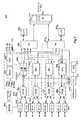
図5は、本発明の実施の形態による記憶スイッチ204の機能ブロック図である。1つの実施の形態では、記憶スイッチ204は複数のラインカード502、504及び506と、複数のファブリック・カード508と、2つのシステム制御カード510とを含む。以下に、各々を詳細に説明する。 FIG. 5 is a functional block diagram of the
システム制御カード
2つのシステム制御カード510の各々は、全てのラインカード502、504、506に接続している。1つの実施の形態では、このような接続は、SCCとのイーサネット接続を介して周知のI2C信号により形成される。SCCは、I2C接続により、電源投入の制御と、個別のラインカード及びファブリック・カードの監視をする。イーサネット接続を介してのカード内通信を使用して、SCCはさまざまな記憶サービス、例えば、仮出願番号第60/325,704号に記載されるスナップショップ及び複製、を開始する。System Control Card Each of the two
さらに、SCCは、スイッチに接続された物理的装置と、例えば、サーバー及び記憶装置と、全ての仮想ターゲットと、記憶スイッチとの構成情報を追跡するデータベース512を維持する。さらに、データベースは、使用、エラー、アクセス・データ、ユーザ、仮想ターゲットのドメイン組及び異なるドメインに関する情報を維持する。データベースのレコードは、ここでは「オブジェクト」と呼ばれる。イニシエーター(例えば、サーバー)及びターゲット(例えば、記憶装置)は、周知のワールド・ワイド・ユニーク識別子(WWUI)を持つ。データベースは、SCC内のメモリ装置内に維持される。1つの実施の形態では、メモリ装置はフラッシュ・メモリから形成されている。しかし、他のメモリ装置も満足である。 In addition, the SCC maintains a
記憶スイッチ204は、管理ステーション210によりイーサネット接続を使用してSCC510を介して到達できる。従って、SCCは、管理ステーションに接続するために追加のイーサネット・ポートを含む。 The
2つのSCC510の内の1つは主動作SCCである。他は予備であり、記憶スイッチ中の動作に同期しているが、直接にはそれらを制御しない。SCCは、もし1つのSCCが故障したならば、他が主コントローラとなるという、高度の利用可能性モードで動作する。 One of the two
ファブリック・カード
スイッチ204の1つの実施の形態では、3つのファブリック・カード508が存在する。他の実施の形態では、より多い又は少ないファブリック・カードを持つことができる。1つの実施の形態では、各ファブリック・カード508は、ラインカード502、504、及び506の各々に接続し、全てのラインカードを一緒に接続する役割を果たす。1つの実施の形態では、ファブリック・カード508の各々は、全てのラインカードが充たされている時、最大トラフイックを処理できる。各ラインカードにより処理されるこのようなトラフイック負荷は、1つの実施の形態で、160Gbpsまでである。他の実施の形態では、より高い又は低い最大トラフイック容積を処理できる。もし、1つのファブリック・カード508が故障した場合、2つの生き残ったカードは可能な最大スイッチ・トラフイック:1つの実施の形態では、各ラインカードは20Gbpsのトラフイック、10Gbps入場及び10Gbps出場を発生する、に対する十分な帯域幅をまだ持つ。しかし、通常の環境下では、3つの全てのファブリック・カードが同時に活動する。各ラインカードから、データ・トラフイックがデータを収容できる3つのファブリック・カードのいずれか1つに送信される。In one embodiment of the
ラインカード
ラインカードは、サーバー装置及び記憶装置への接続を形成する。1つの実施の形態では、記憶スイッチ204は、16ラインカードまで支援する。他の装置では異なる数を支援できる。さらに、1つの実施の形態では、3つのタイプのラインカードが使用される。ギガビット・イーサネット(GigE)カード502と、ファイバー・チャンネル(FC)カード504と、WANカード506とである。他の実施の形態はより多い又は少ないタイプのラインカードを含んでも良い。GigEカード502は、1つの実施の形態ではiSCSIサーバー又はiSCSI記憶装置(又は、他のイーサネット・ベース装置)のいずれかに接続する、イーサネット接続用である。FCカード504は、ファイバー・チャンネル・プロトコル(FCP)サーバー又はFCP記憶装置のいずれかに接続するファイバー・チャンネル接続用である。WANカード506は、MAN又はWANに接続するためである。Line Card Line cards form connections to server devices and storage devices. In one embodiment, the
図6は、本発明の実施の形態による記憶スイッチ204に使用される一般的なラインカード600の機能ブロック図を示す。この図は、全てのタイプのラインカード、例えば、GigE502、FC504、又はWAN506、において共通なコンポーネントを示す。他の実施の形態では、ラインカードの他のタイプが、インフイニバンドなどの他のプロトコルを使用する装置へ接続するために使用できる。ラインカードの相異点は後で説明する。 FIG. 6 shows a functional block diagram of a
ポート
各ラインカード600は、複数のポート602を含む。ポートは、サーバー又は記憶装置のいずれかへのラインカードの接続を形成する。図示された実施の形態では8つのポートが示されているが、他の実施の形態ではより多い又は少ないものが使用できる。例えば、1つの実施の形態では、各GigEカードは8つまでの1Gbイーサネット・ポートを支援でき、各FCカードは8つの1GbFCポート又は4つの2GbFCポートのいずれかまでを支援でき、各WANカードは4つのOC−48ポート又は2つのOC−192ポートのいずれかまでを支援できる。従って、1つの実施の形態では、最大の可能な接続は、スイッチ204当たり128ポートである。各ラインカードのポートは、フルデュプレックスであり、サーバー又は他のクライアントのいずれか、又は、記憶装置又はサブシステムへ接続する。Port Each
さらに、各ポート602は、付随メモリ603を持つ。単に1つのメモリ装置が1つのポートに接続されているのが示されているが、各メモリポートはそれ自身のメモリ装置を有してよく、また、全てのポートが単一のメモリ装置へ接続してもよい。説明の簡潔のため、単一のメモリ装置がここでは1つのポートに接続されているのが示されている。 Further, each
記憶プロセッサ・ユニット
1つの実施の形態では、各ポートは記憶プロセッサ・ユニット(SPU)601と関連付けられる。1つの実施の形態では、SPUは、データ・トラフイックを高速に処理して、ワイヤ速度操作を可能にする。1つの実施の形態では、SPUはいくつかの要素:パケット集合及び分類エンジン(PACE)604、パケット処理ユニット(PPU)606、SRAM605、及びCAM607、を含む。他の実施の形態はより多い又は少ない要素を使用でき、また、同じ機能を得るために要素を結合できる。例えば、いくつかの実施の形態は、SPU内にPACE及びPPUを含むが、SPUはメモリ要素を他のSPUと共有することができる。Storage Processor Unit In one embodiment, each port is associated with a storage processor unit (SPU) 601. In one embodiment, the SPU processes data traffic at high speed to allow wire speed operation. In one embodiment, the SPU includes several elements: packet set and classification engine (PACE) 604, packet processing unit (PPU) 606,
PACE
各ポートは、パケット集合及び分類エンジン(PACE)604に接続されている。図示されるように、PACE604は2つのポートを二倍の帯域幅を有する単一データ・チャンネルに集合する。例えば、PACE604は、2つの1Gbポートを単一の2Gbデータ・チャンネルに集合する。PACEは、仮出願番号第60/325,704号に記載されるように、各受信パケットを制御パケット又はデータパケットに分類する。制御パケットは処理のためにブリッジ616を経由してCPU614へ送られる。データパケットは以下に説明するパケット処理ユニット(PPU)606へ追加されたローカル・ヘッダと共に送信される。1つの実施の形態では、ローカル・ヘッダは、16バイトであり、64バイトのデータ「セル」を生ずる(16バイトのヘッダ及び48バイトのペイロード)。ローカル・ヘッダは、情報を運ぶために使用され、スイッチ204により内部的に使用される。ローカル・ヘッダは、パケットがスイッチを去る前に除去される。従って、ここで使用される「セル」はスイッチ内で局所的に使用される移送単位であり、ローカル・ヘッダとオリジナル・パケット(いくつかの実施の形態では、元のTCP/IPヘッダも元のパケットから除去される)を含む。しかし、本発明の全ての実施の形態がローカル・ヘッダを作成し、外部パケットとは異なる「内部パケット」(セル)を持つのではない。従って、ここで使用される言葉「パケット」は「内部」又は「外部」パケットのいずれかを指すことができる。PACE
Each port is connected to a packet aggregation and classification engine (PACE) 604. As shown,
分類機能は、スイッチが、従来システムの記憶及び転送モデルを使用せずに、ワイヤ速度で記憶仮想化及びプロトコル翻訳機能を実行可能にすることを助ける。各PACEはPPU606への専用化経路を持つが、図示された実施の形態中の4つのPACEの全ては、CPU614への経路を共有する。これは、1つの実施の形態では、104MHz/32(3.2Gbps)ビット・データ経路である。 The classification function helps the switch to perform storage virtualization and protocol translation functions at wire speed without using the traditional system storage and transfer model. Each PACE has a dedicated path to the
パケット処理ユニット(PPU)
PPU606は、オンザフライで仮想化及びプロトコル翻訳を実行する。これはセルは、仮出願番号第60,325704号に記載されるように、この処理のためにバッフアされないことを意味する。また、後述する他のスイッチ・ベース記憶サービス機能を実行する。1つの実施の形態では、PPUは、セルを入場と出場の両方向へ、OC−48速度又は2.5Gbpsで移動できる。他の実施の形態では、セルをOC−192速度又は10Gbpsで移動できる。1つの実施の形態では、PPUは、共に同時的に動作する入場PPU6061及び出場PPU6062を含む。入場PPU6061は、PACE604から入来するデータを受信して、データをトラフイック・マネージャ608iヘ送信する。出場PPU6062は、トラフイック・マネージャ608eからデータを受信して、データをPACE604へ送信する。図6に示されるただ1つのPPU606が入場PPU6061及び出場PPU6062を有するが、1つの実施の形態では全てのPPU606が入場及び出場PPUの両方を含むことが理解される。説明の簡潔さのため、図6に示されるただ1つのPPUのみが入場及び出場PPUの両方を備えている。Packet processing unit (PPU)
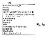
多数の記憶接続(例えば、サーバーから仮想ターゲット)が、各ポートで同時に確立できる。しかし、各接続は仮想ターゲットに対して独特であり、TCP制御ブロック・インデックス(iSCSI接続の場合)及びポート番号により独特に識別できる。接続が確立される時、ラインカード600のCPU614は、PPU606に活動仮想ターゲットをそれに接続ために仮想ターゲット記述子(VTD)を送信することにより知らせる。VTDは、PPUがデータについて適当に動作、例えば、仮想化、翻訳、及びさまざまな記憶サービスの実行、をするのに必要な仮想ターゲット及び接続とに関する全ての関連情報を含む。VTDは、SCCデータベース中のオブジェクトから導出され、普通、SCCデータベース中の関連オブジェクト中に記憶されている情報の小組を含む。図7aに本発明の1つの実施の形態のVTD中のフィールドの例が示される。しかし、本発明の他の実施の形態は、より多い、少ない又は異なるフィールドを持つことができる。 Multiple storage connections (eg, server to virtual target) can be established simultaneously on each port. However, each connection is unique to the virtual target and can be uniquely identified by the TCP control block index (for iSCSI connections) and port number. When a connection is established, the
同様に、物理的ターゲット記述子(PTD)が、本発明の実施の形態で使用される。PTDは、現実の物理的装置、それらの個別のLU、又はそれらの個別のエクステント(全体LU又は連続する部分)を記述し、そしてVTDのそれと同様な情報を含む。また、VTDと同じく、PTDはSCCデータベース中のオブジェクトから導出される。図7bに本発明の1つの実施の形態のPTDのフィールドの例を示す。しかし、本発明の他の実施の形態は、より多い、少ない又は異なるフィールドを持つことができる。 Similarly, a physical target descriptor (PTD) is used in embodiments of the present invention. The PTD describes real physical devices, their individual LUs, or their individual extents (entire LUs or contiguous parts) and contains information similar to that of VTDs. Also, like VTD, PTD is derived from objects in the SCC database. FIG. 7b shows an example of the field of the PTD according to one embodiment of the present invention. However, other embodiments of the invention can have more, fewer, or different fields.
VTD及びPTDを記憶してそれらに高速にアクセスするために、1つの実施の形態では、PPU606がSRAM605及びCAM607に接続されている。SRAM605は、VTD及びPTDデータベースを記憶する。また、VTD識別子(VTDID)又はアドレス、及びPTD識別子(PTDID)のリストが、VTDの高速アクセスのためにPPUCAM607中に維持される。VTDIDは、TCP制御ブロック・インデックス及びLUNを用いてインデックス(マップ)される。PTDIDは、VTDIDを使用してインデックスされる。さらに、IPルーテイング・サービスのために、CAM607は、経路が追加又は除去された時にCPUにより更新される経路テーブルを含む。 In order to store VTD and PTD and access them at high speed, in one embodiment,
単に1つのCAM及びSRAが、1つのPPUに接続するように示されているが、これは図面の簡潔さを維持するためであることに注意する。さまざまの実施の形態では、各PPUはそれ自身のCAM及びSRAM装置に接続されるか、又は、PPUは単一のCAM及び/又はSRAMに全て接続される。 Note that although only one CAM and SRA are shown connecting to one PPU, this is to maintain the simplicity of the drawing. In various embodiments, each PPU is connected to its own CAM and SRAM device, or the PPU is all connected to a single CAM and / or SRAM.
PPUへの各未決の要求については(例えば、読出し又は書込み)、要求の状態を追跡するためにタスク制御ブロックがPPUSRAM607中に設定される。入場PPU上の記憶スイッチにより受信された要求の状態を追跡する入場タスク制御ブロック(ITCB)及び出場PPU上の記憶スイッチにより送信される要求の状態を追跡する出場タスク制御ブロック(ETCB)が存在する。各仮想ターゲット接続については、多数の同時的要求が存在し得、従って、多くのタスク制御ブロックが存在し得る。タスク制御ブロックは要求が開始される時に割当てられ、要求が完了する時に解放される。 For each pending request to the PPU (eg, read or write), a task control block is set in
トラフイック・マネージャ
各ラインカード600上に2つのトラフイック・マネージャ(TM)608:入場トラフイックのための1つのTM608i及び出場トラフイックのための1つのTM608e、が存在する。1つの実施の形態では、入場TMは64バイト・データセルの形式のセルを全ての4つのSPUから受信する。このような実施の形態では、各データセルは、16バイトのローカル・ヘッダと48バイトのペイロードを持つ。ヘッダは、TMにセルの宛先ポートを知らせるフローIDを含む。いくつかの実施の形態では、SPUはまた、セルをTMへ転送する前にTMヘッダをセルに取付けてもよい。また、いくつかの実施の形態では、TM又はSPUのいずれかは、セルをファブリック・カードを通じての送信のためにより小さいセルに分割できる。There are two traffic managers (TM) 608 on each line card 600: one TM608i for admission traffic and one TM608e for admission traffic. In one embodiment, the admission TM receives cells in the form of 64-byte data cells from all four SPUs. In such an embodiment, each data cell has a 16-byte local header and a 48-byte payload. The header includes a flow ID that informs the TM of the destination port of the cell. In some embodiments, the SPU may also attach a TM header to the cell before transferring the cell to the TM. Also, in some embodiments, either TM or SPU can divide cells into smaller cells for transmission through the fabric card.
入場TMは、1つの実施の形態では、データセルを128ビット104Mhzインターフェイス610を経由してファブリック・カードへ送信する。他の実施の形態では、125Mhz又は他の速度で動作する。出場TMはファブリック・カードからデータセルを受信してそれらを4つのSPUへ配達する。
入場及び出場TMの両方は、配達のためにセルを待ち行列させるための大きなバッフア612を持つ。入場及び出場TMのための両バッフア612は、64MBであり、多数のパケットを待ち行列できる。SPUは、普通、ファブリック・カードの出力流れは入力流れと同じ程度に速いので、セルを入場TMへ素早く送信できる。従って、セルは素早く出場TMへ移動する。一方、出場TMは、出力ポートが渋滞又は複数の入場ラインカードにより供給されるため、バックアップされてよい。このような場合、操作を素早くするように出力SPUに知らせるため、出力セルのヘッダ中にフラグが設定される。また、出場TMは、以下に説明する記憶アクセスのためのサービスの品質を提供する際に使用される流れ制御機能を活性化するために、入場SPUへ要求を送信する。インターネット上の通信トラフイックとは異なり、記憶トラフイックに対しては、パケット又はセルを落とすことは許されないことに注意する。従って、バッフア中のセルの量が指定された閾値を越えると直ちに、SPUはバッフアのオーバーフローを避けるために入力トラフイックを遅くするためその流れ制御機能を活性化する。The admission TM, in one embodiment, transmits the data cells to the fabric card via the 128 bit 104
Both the entry and exit TMs have a
ファブリック接続
ファブリック接続610は、TMの256ビット・パラレル信号(それぞれ、128ビット入場及び128ビット出場)を、160Gbpsのバックプレーンへの16ビット・シリアル・インターフェイス(8ビット入場及び8ビット出場)へ変換する。従って、バックプレーンは、16分の1のピンで16倍早い速度で動作している。この変換は、数千の接続ピンとワイヤを無しに合理的なコストで高い利用可能度のバックプレーンの構成を可能にする。さらに、1つの実施の形態では3つのファブリック・カードが存在するため、1つの実施の形態では各ラインカード上に3つの高速コネクタが存在し、これらコネクタの各々は8ビット信号を3つのファブリック・カードのそれぞれに接続する。もちろん、他の実施の形態は3つのファブリック・カード610を必要としないであろう。Fabric
CPU
各ラインカード上には、プロセッサ(CPU)614が存在する。1つの実施の形態では、プロセッサはパワーPC750Cxeである。1つの実施の形態では、CPU614は、バス・コントローラ615とブリッジ616とを経由して3.2Gbバスにより各PACEに接続する。さらに、CPU614は各PPU、CAM及びTMにも接続する。しかし、いくつかの実施の形態では、この接続はより遅い40Mbpsである。3.2Gb及び40Mbpsの両経路はCPUがラインカード中の大部分の装置と通信することを可能にし、そしてラインカード上の全ての装置の内部レジスタを読取り及び書込むことを可能にし、マイクロコードをダウンロードし、そして制御パケットを送信及び受信することを可能にする。CPU
A processor (CPU) 614 exists on each line card. In one embodiment, the processor is a Power PC 750Cxe. In one embodiment,
各ラインカード上のCPUは、電源投入時に各チップを初期化する責任を持ち、SPU及びマイクロコードが必要な各ポートへマイクロコードをダウンロードする。ラインカードが動作状態になると、CPUは制御トラフイックを処理する。仮想ターゲット接続を確立するのに必要な情報については、CPUはSCCから情報を要求し、次にSCCデータベース中の適当なオブジェクトから情報を得る。 The CPU on each line card is responsible for initializing each chip when power is turned on, and downloads microcode to each port that requires SPU and microcode. When the line card becomes operational, the CPU processes control traffic. For information required to establish a virtual target connection, the CPU requests information from the SCC and then obtains the information from the appropriate object in the SCC database.
ラインカード−ポートの区別
ラインカードの各タイプのポート、例えば、GigE、FC、又はWANは、1つの実施の形態では各ラインカードは1つのタイプのポートのみを支援するため、別個である。以下に1つの実施の形態のポートの各タイプについて説明する。もちろん、別の実施の形態では、インフイニバンドなどの他のプロトコルを支援するため、他のラインカード・ポートが設計できる。Line Card-Port Differentiation Each type of port on the line card, eg, GigE, FC, or WAN, is separate because in one embodiment each line card supports only one type of port. Each type of port according to one embodiment will be described below. Of course, in other embodiments, other line card ports can be designed to support other protocols such as InfiniBand.
GigEポート
ギガビット・イーサネット・ポートは、iSCSIサーバーと記憶装置に接続する。GigEポートは全ての種類のイーサネット・トラフイックを運ぶが、本発明の1つの実施の形態によるワイヤ速度で記憶スイッチ204により一般に処理されるネットワーク・トラフイックは、TCP/IPパケット中のiSCSIパケットデータユニット(PDU)だけである。しかし、他の実施の形態では、イーサネット上を運ばれる他のプロトコル(ネットワーク・ファイル・システム(NFS)のような)によるパケットが、GigEポートで受信されて、SPU及び/又はCPUにより処理されてよい。GigE port The Gigabit Ethernet port connects to the iSCSI server and storage device. Although GigE ports carry all types of Ethernet traffic, network traffic that is typically handled by the
GigEポートは、仮想ターゲット又はiSCSI装置のためにTCP/IPセグメントを送受信する。仮想ターゲットのためにTCP接続を確立するために、ラインカードCPU614とSCC510の両方が関与する。TCPパケットが受信される時、そして初期のハンドシェーキングが行われた後、TCP制御ブロックが生成されて、GigEポート・メモリ603中に格納される。また、接続を認証して仮想ターゲットの構成を理解する目的のため、VTDがSCCデータベースのオブジェクトから検索されて、CPUSDRAM605中に記憶される。TCP制御ブロックは、パケットが所属しそして1つの実施の形態ではTCPセグメント番号、状態、ウインドウ大きさ、及び接続に関する潜在的に他の情報を含む特定のTCPセッション又はiSCSI接続を識別する。さらに、TCP制御ブロックは、ここで「TCP制御ブロック・インデックス」と呼ばれるインデックスにより識別される。接続のためのVTDが作られて、SPURAM605中に記憶されなければならない。CPUは、そのSDRAM中に記憶されていて、元はSCCデータベースから得られたVTD情報を検索することにより、VTDを作成する。VTDIDが、VTDの素早い参照のためにSPUCAM607中のVTDIDのリスト中に設定される。VTDIDは、TCP制御ブロック・インデックスと合併され、そしてインデックスされる。 The GigE port sends and receives TCP / IP segments for virtual targets or iSCSI devices. Both the
ポートが、iSCSIPDUを受信する時、本質的にその接続の終了点として機能するが、その後にスイッチがターゲットへの新しい接続を始める。入場側でパケットを受信した後、ポートは、特定のTCP接続を識別するTCP制御ブロック・インデックスによりPACEへiSCSIPDUを配達する。非TCPパケット又はiSCSIPDUを含まないTCPパケットについては、ポートは接続の終点として動作することなくパケットを受信しそして送信する。典型的に、ポート602は、iSCSIパケットがTCP制御ブロック・インデックスを使用して受信又は送信されるPACE604と通信する。パケットのTCP制御ブロック・インデックスが、−1の時、それは非iSCSIパケットを識別する。 When a port receives an iSCSI PDU, it essentially serves as the end point for that connection, but then the switch initiates a new connection to the target. After receiving the packet on the entrance side, the port delivers the iSCSI PDU to the PACE with a TCP control block index that identifies the particular TCP connection. For non-TCP packets or TCP packets that do not contain iSCSI PDUs, the port receives and transmits the packet without acting as a connection endpoint. Typically,
FCポート
FCポートは、サーバー及びFC記憶装置に接続する。FCポートは、接続するサーバーにファイバー・チャンネル記憶サブシステム(すなわち、ターゲット)として見える。それはイニシエーター(例えば、サーバー)が接続を確立するために業界で知られているプロセス・ログイン(PLOGI又はPRLI)を実行することを可能にする仮想ターゲット装置の大きなプールを表すことを意味する。FCポートは、GID拡張リンクサービス(ELS)を受け取り、そしてそのイニシエーター(例えば、サーバー)によるアクセスのために利用可能なターゲット装置のリストを戻す。FC port The FC port connects to the server and the FC storage device. The FC port appears to the connecting server as a Fiber Channel storage subsystem (ie, target). It is meant to represent a large pool of virtual target devices that allow initiators (eg, servers) to perform industry known process logins (PLOGI or PRLI) to establish a connection. The FC port receives the GID Extended Link Service (ELS) and returns a list of target devices available for access by its initiator (eg, server).
ファイバー・チャンネル記憶装置に接続する時、ポートはファイバー・チャンネルFポートとして見え、記憶装置から業界で知られているファブリック・ログインを受け取り、そしてGID要求を受け取りそして処理することにより名前サービス機能を提供することを意味する。換言すれば、ポートは記憶装置にはイニシエーターとして見える。 When connecting to a Fiber Channel storage device, the port appears as a Fiber Channel F port, receives the industry-known fabric login from the storage device, and provides name service functionality by receiving and processing GID requests It means to do. In other words, the port appears to the storage device as an initiator.
さらに、FCポートは別の既存のSANネットワークに接続でき、このような例では他のネットワークには多くのLUを持つターゲットとして見える。 Furthermore, the FC port can be connected to another existing SAN network, and in such an example, the other network appears as a target with many LUs.
ポートの初期化では、ラインカードCPUはファブリック・ログイン、プロセス・ログイン、及びGIDを送信し、そして同じものを受信する両方を完了しなければならない。SCCは、FCELSをiSNS要求及び応答に変換するためのアプリケーションを支援する。この結果、SCC内の同じデータベースは、あたかもそれらがiSCSIイニシエーター及びターゲットであるかのように、FCイニシエーター(例えば、サーバー)及びターゲット(例えば、記憶装置)の両方を追跡する。 At port initialization, the line card CPU must complete both sending the fabric login, process login, and GID and receiving the same. SCC supports applications for converting FCELS into iSNS requests and responses. As a result, the same database in the SCC tracks both FC initiators (eg, servers) and targets (eg, storage devices) as if they were iSCSI initiators and targets.
FC接続を確立する時、GigEポートとは異なり、FCポートはTCP制御ブロック又はその等価物を生成する必要がない。必要な全ての情報はFCヘッダから利用可能である。しかし、VTD(D_IDによりインデックスされる)はGigEポートについて説明したのと同様な態様で確立される必要がある。 When establishing an FC connection, unlike a GigE port, the FC port need not generate a TCP control block or its equivalent. All necessary information is available from the FC header. However, the VTD (indexed by D_ID) needs to be established in the same manner as described for the GigE port.
FCポートは、1Gb又は2Gbとして構成できる。1Gbポートとして、図6に示すように、2つのポートが単一のPACEへ接続されるが、2Gbポートとして構成される1つの実施の形態では、ポート・トラフイック及びSPUにより収容可能なトラフイックは、SPUでの渋滞を避けるために一致すべきである。1つの実施の形態では、ポートはPOS/PHYインターフェイスによりPACEへ接続される。各ポートは別個に構成できる。すなわち、1つのPACEは2つの1Gbポートを持つことができ、そして別のPACEは単一の2Gbポートを持つ。 The FC port can be configured as 1 Gb or 2 Gb. As a 1 Gb port, as shown in FIG. 6, two ports are connected to a single PACE, but in one embodiment configured as a 2 Gb port, the traffic that can be accommodated by the port traffic and SPU is: Should be consistent to avoid congestion at the SPU. In one embodiment, the port is connected to PACE by a POS / PHY interface. Each port can be configured separately. That is, one PACE can have two 1 Gb ports and another PACE has a single 2 Gb port.
WANポート
WANラインカードを含む実施の形態では、WANラインカードは1つの実施の形態ではOC−48及びOC−192接続を支援する。従って、2つのタイプのWANポート:OC−48及びOC−192が存在する。OC−48については、各SPUに対して1つのポートが存在する。PACEには集合機能はないが、分類機能が存在する。WANポートはSONETに接続し、そしてそれはICMP、RIP、BPG、IP及びTCPなどのネットワーク・パケットを送信及び受信する時、GigEポートのように動作する。GigEポートとは異なり、WANポートは1つの実施の形態では、追加のハードウェア部品を必要とするIPSecとVPNによりネットワーク・セキュリテイを支援する。
OC−192はより高速のワイヤ速度を生ずるので、OC−192を支援する実施の形態ではより高速のSPUが必要とされる。In an embodiment that includes aWAN port WAN line card, the WAN line card supports OC-48 and OC-192 connections in one embodiment. Thus, there are two types of WAN ports: OC-48 and OC-192. For OC-48, there is one port for each SPU. PACE does not have an aggregation function, but a classification function exists. The WAN port connects to SONET and it behaves like a GigE port when sending and receiving network packets such as ICMP, RIP, BPG, IP and TCP. Unlike GigE ports, WAN ports support network security with IPSec and VPN, which in one embodiment requires additional hardware components.
Since OC-192 produces higher wire speeds, higher speed SPUs are required in embodiments that support OC-192.
スイッチに基づいた記憶動作
本発明の実施の形態による記憶スイッチは、プーリング及び供給を含む、さまざまなスイッチに基づいた記憶動作を実行する。記憶アクセスのためのサービスの品質及び負荷平衡の各々について以下に説明する。
iSCSI及びFCプロトコルの一般的な知識は仮定される。iSCSIのさらなる情報に関しては、参照によりここに組み込まれた、インターネット・ドラフト及びインターネット・エンジニアリング・タスク・フォース(IETF)による、2001年11月19日の進行中の作業、“draft−ietf−ips−iSCSI−09.txt”を参照。ファイバー・チャンネル(FC)のさらなる情報に関しては、参照によりここに組み込まれた、“情報システム−SCSI用dpANSファイバー・チャンネル・プロトコル”Rev.012、1995年12月4日(アメリカン・ナショナル・スタンダードの提案草案)を参照。さらに、両方は仮出願番号第60/325,704号に記載されている。Storage operations based on switches Storage switches according to embodiments of the invention perform storage operations based on various switches, including pooling and feeding. Each of the quality of service and load balancing for storage access is described below.
General knowledge of iSCSI and FC protocols is assumed. For further information on iSCSI, see “draft-ietf-ips-” on-going work on 19 November 2001 by the Internet Draft and Internet Engineering Task Force (IETF), which is incorporated herein by reference. See iSCSI-09.txt ". For more information on Fiber Channel (FC), see “Information System-dpANS Fiber Channel Protocol for SCSI” Rev., incorporated herein by reference. 012, December 4, 1995 (American National Standard Proposal Draft). Furthermore, both are described in provisional application No. 60 / 325,704.
記憶プール
図2の物理的な構成に示すように、本発明の実施の形態によるシステムは、1つ又は複数のサーバー202及び1つ又は複数の物理的装置206、すなわち、記憶装置又はサブシステム、に接続されたスイッチ204を含む。各物理的ターゲットは、1つ又は複数の論理的ユニット(LU)207を含む。仮想ターゲットが最終的に形成されるのはこれらLUからである。Storage Pool As shown in the physical configuration of FIG. 2, a system according to an embodiment of the present invention includes one or
しかし、仮想ターゲットが生成、又は「供給」できる前に、スイッチは取付けられた及び/又はそれによりアクセス可能な物理的記憶装置及びそれらの物理的記憶装置の特性を「知る」ことが必要である。従って、本発明の1つの実施の形態では、記憶装置又はイニシエーター装置がスイッチに接続又は登録される時、スイッチは新装置の性能特性について学ばなければならない。1つの実施の形態では、スイッチは記憶アクセス時間、データ転送速度、キャシュ支援、装置への代替経路の数、RAID支援、及び物理的装置のLUに対する許容最大命令を測定できるユーテイリテイ・プログラムを含む。いくつかの実施の形態では、一旦、装置がスイッチに接続されると、ユーテイリテイ・プログラムが自動的に装置を発見して、そして必要な情報をユーザ又は他の介在なしに自動的に集める。このような実施の形態では、スイッチはポートへの信号線のリセット又は撹乱がある時、装置の追加/削除を発見する。装置が発見されると、性能特性に関する情報を集めるために装置へさまざまな質問が送られる。例えば、読出し/書込み命令が転送速度を測定し又はアクセス時間を検査するために送信できる。代替的に、いくつかの実施の形態では、性能特性を得ることは、管理者が管理ステーション210で性能特性を入力することにより行うことができ、そして、特性はスイッチ204へ供給される。 However, before a virtual target can be created or “provisioned”, the switch needs to “know” the physical storage devices attached and / or accessible thereby and the characteristics of those physical storage devices. . Thus, in one embodiment of the present invention, when a storage device or initiator device is connected or registered to the switch, the switch must learn about the performance characteristics of the new device. In one embodiment, the switch includes a utility program that can measure storage access time, data transfer rate, cache assistance, number of alternate paths to a device, RAID assistance, and maximum allowable instructions for a physical device LU. In some embodiments, once the device is connected to the switch, the utility program automatically discovers the device and automatically collects the necessary information without any user or other intervention. In such embodiments, the switch discovers device additions / removals when there is a signal line reset or disturbance to the port. When a device is discovered, various questions are sent to the device to gather information about performance characteristics. For example, read / write commands can be sent to measure transfer rates or check access times. Alternatively, in some embodiments, obtaining performance characteristics can be performed by an administrator entering performance characteristics at the
全てにエンドユーザに対して一般に見えない、装置に関して集められた情報に基づき、本発明の1つの実施の形態では、スイッチはポリシーに基づき装置を分類する。例えば、最良特性を持つ装置はプラチナ装置として分類される。中間的な性能特性を持つ装置はゴールド又はシルバー装置として分類される。最低の性能特性を持つ装置はブロンズ装置として分類される。もちろん、定義されるタイプのポリシーは無限であり、本発明の実施の形態中で変化する。さらに、いくつかの実施の形態では、管理者は、例えば、プラチナ・ビルデイング1、プラチナ・ビルデイング2のようにポリシーを再分割でき、そしてこのように再分割されたポリシーへ資源を割当てる。しかし、本発明の1つの実施の形態に使用されるポリシーの一例を以下の表1に示す。 Based on information gathered about the devices that is not generally visible to the end user, in one embodiment of the invention, the switch classifies the devices based on policies. For example, the device with the best characteristics is classified as a platinum device. Devices with intermediate performance characteristics are classified as gold or silver devices. Devices with the lowest performance characteristics are classified as bronze devices. Of course, the types of policies defined are infinite and vary in the embodiments of the present invention. Further, in some embodiments, an administrator can subdivide policies, for example,
表1
図8に示すように、一旦、ポリシーが記憶装置に対して決定されると、その装置のLUが、時々、「ドメイン」とここで呼ばれる、記憶プール802へ割当てられてられる。各記憶装置が1つ又は複数のLUを含むため、特定の記憶装置の全てのLUは同じプールに割当てられる。しかし、1つの実施の形態では、各LUはスイッチにより別個の記憶ノードとしてみなされ、そして各LUはSCCデータベース512内のLUオブジェクトにより記述される。従って、各プールはメンバーとしてLUを有する。1つの実施の形態では、プールへの割当ては物理的記憶装置が動作する、例えば、iSCSI又はファイバー・チャンネル、プロトコルとは独立に実行される。当業者には理解されるように、各プールはLUがそれに割当てられたプールに関するリストによりスイッチ中で定義され、そのリストは1つの実施の形態ではSCCデータベース512中に記憶される。このようなリストはLUオブジェクトへのポインタを含む。 As shown in FIG. 8, once a policy is determined for a storage device, that device's LU is assigned to a storage pool 802, sometimes referred to herein as a "domain". Since each storage device includes one or more LUs, all LUs of a particular storage device are assigned to the same pool. However, in one embodiment, each LU is considered as a separate storage node by the switch, and each LU is described by an LU object in the
一般に、各プールは、特定の性質を持つユーザのみによりアクセス可能である。例えば、記憶プールはビルデイング1にいるユーザのために設立でき、プールは「ビルデイング1共有ゴールド記憶プール」と命名される。別の例示的なプールは「エンジニアリング専用シルバー記憶プール」と命名されて、特定の会社のエンジニアリング・チームにより専用にアクセスされてよい。もちろん、プールの無限の変形が設定でき、ここに記載されて示されるものは例示のみである。 In general, each pool is accessible only by users with certain properties. For example, a storage pool can be established for a user at
さらに、1つの実施の形態では、2つの特別なプールが存在する。「デフォルト・プール」と「ノー・プール」である。デフォルト・プールは、記憶ネットワークへアクセスするだれにもアクセスを許容する。これに対して、「ノー・プール」は、一般的にユーザにアクセス可能ではなく、スイッチ自身又はシステム管理者のみにアクセス可能である。一旦、プールに割当てられると、LUはスイッチ自身又はシステム管理者により異なるプールへ再割当てできる。例えば、LUは最初はノー・プール中に置かれて、テストされて、そして後で、デフォルト・プール又は他のプールへ移動される。 Furthermore, in one embodiment, there are two special pools. “Default pool” and “No pool”. The default pool allows access to anyone accessing the storage network. In contrast, a “no pool” is generally not accessible to the user, but only accessible to the switch itself or the system administrator. Once assigned to a pool, the LU can be reassigned to a different pool by the switch itself or the system administrator. For example, LUs are initially placed in a no pool, tested, and later moved to the default pool or other pools.
サービスの品質及びサービス・レベル・アグリメント
サービス・レベル・アグリメント(SLA)は、時々、ネットワーク通信中で使用されるが、記憶ネットワークの文脈で一般的には使用されておらず、サービスの品質(QoS)ポリシーと共に記憶ネットワーク中に使用されてはいない。SLA/QoSを提供することにより、ユーザはデータの記憶及び検索の条件を選択できる。1つの実施の形態では、QoSポリシーは、3つの要素:仮想ターゲットの供給、イニシエーター接続の供給、及びユーザ・ドメインの定義により定義される。以下に各々が説明される。しかし、いくつかの実施の形態は、QoSポリシーを定義するために3つの全ての定義を必要としない。例えば、いくつかの実施の形態は、仮想ターゲットの供給、及びイニシエーター接続の供給のみを必要とし、ユーザ・ドメインの定義を必要としない。他の実施の形態では、QoSポリシーを定義するために全く異なる要素を使用してよい。Quality of service and service level agreements Service level agreements (SLAs) are sometimes used in network communications, but are not commonly used in the context of storage networks. Not used in storage networks with (QoS) policies. By providing SLA / QoS, the user can select data storage and retrieval conditions. In one embodiment, the QoS policy is defined by three elements: virtual target provisioning, initiator connection provisioning, and user domain definition. Each is described below. However, some embodiments do not require all three definitions to define a QoS policy. For example, some embodiments only require provisioning of virtual targets and provisioning of initiator connections, and no definition of user domains. In other embodiments, completely different elements may be used to define the QoS policy.
仮想ターゲットの供給
物理的装置についてのLUがアクセス可能プールに存在すると、それらLUについて仮想ターゲットが生成できる。一旦、生成されると、図9に示すように、サーバー(及びそれらのそれぞれのユーザ)は、1つ又は複数の仮想ターゲット902を「見る」であろう。仮想ターゲットは各々が1つ又は複数のエクステント907からなるが、彼等は物理的装置206を必ずしも「見」ない。エクステントは、物理的装置から全体LU又はその隣接する部分である。図9の例に示すように、例示的仮想ターゲット902中の各エクステントは、いくつかの物理的装置からの全体LUにより形成されている。なお、「エクステント」は、ターゲットが「仮想」であることを自覚しないサーバーなどのイニシエーターからLUNにより参照できる。LUにより使用されるプロトコルを含む仮想ターゲットの構造は、サーバーとは関連性がない。しかし、図9に示すように、各仮想ターゲットは物理的装置206のLUへマップするエクステントからなる。Supplying virtual targets If LUs for physical devices are present in the accessible pool, virtual targets can be created for those LUs. Once created, the servers (and their respective users) will “see” one or more
仮想ターゲットを供給するために、ユーザは本発明の1つの実施の形態において仮想ターゲットのためのいくつかの特性を選択する。特性は以下を含む。
・大きさ(例えば、ギガバイト単位)、
・記憶プール、1つの実施の形態では、ユーザはユーザがアクセスを許された記憶プールだけから選択するが、
・所望の利用可能性、例えば、常に利用可能(データが重要で、ダウンすること許されない)、普通の利用可能性等、
・仮想ターゲットのWWUI、
・バックアップ・プール、
・ユーザ認証データ、
・ミラーされたメンバー数、
・ミラーされたメンバーの場所(例えば、ローカル又は遠隔)
また、他の実施の形態では異なる、追加の、又はより少ない特性も選択できる。To supply a virtual target, the user selects several characteristics for the virtual target in one embodiment of the invention. Properties include:
Size (eg, gigabytes),
Storage pool, in one embodiment, the user selects only from the storage pool that the user is allowed to access,
• Desired availability, eg always available (data is important and not allowed to go down), normal availability, etc.
・ Virtual target WWUI,
Backup pool,
・ User authentication data,
・ Number of mirrored members,
Mirrored member location (eg local or remote)
Also, other embodiments can select different, additional, or fewer characteristics.
その後、スイッチは仮想ターゲットが形成できるかどうかを決定するため、そして特にスイッチは仮想ターゲットについて必要の大きさに合うLU(又はLUの部分)の数が利用可能かどうかを決定するため、選択されたプールからの利用可能な資源を解析する。もし、そうであるならば、仮想ターゲットが1つ又は複数のエクステントにより生成される。そして、仮想ターゲット・オブジェクトが、仮想ターゲット、そのエクステント、及びその特性を識別するSCCデータベース内に形成される。以下の表2に4つの仮想ターゲットについてのユーザ選択特性の例が示されている。
The switch is then selected to determine whether the virtual target can be formed, and in particular, the switch is determined to determine whether the number of LUs (or portions of LUs) that fit the required size is available for the virtual target. Analyze available resources from the pool. If so, a virtual target is created with one or more extents. A virtual target object is then formed in the SCC database that identifies the virtual target, its extent, and its characteristics. Table 2 below shows examples of user selection characteristics for four virtual targets.
表2−仮想ターゲット
新仮想ターゲットを供給するのに加えて、本発明の実施の形態によるスイッチは、既存のターゲットを新しい又は異なる情報により修正することもでき、又は、それらがもはや必要でなければ仮想ターゲットを削除できる。 In addition to supplying new virtual targets, the switch according to embodiments of the present invention can also modify existing targets with new or different information, or delete virtual targets if they are no longer needed. .
イニシエーター接続の供給
サーバー又は他のイニシエーターがスイッチへ接続されてそしてイニシエーターがiSNS又はSLPを支援する時、1つの実施の形態では、イニシエーターはそれ自身をスイッチに登録して、イニシエーター・オブジェクトをSCSIデータベース内に記憶する。他の実施の形態では、スイッチはイニシエーター接続を生成し、更新し、又は削除するアクセス供給機能を含む。
アクセス接続−スイッチとイニシエーター(サーバーなど)との間の接続−を生成する際、ユーザは1つの実施の形態の表3に示されるさまざまなパラメータを指定する。When an initiator-connected provisioning server or other initiator is connected to the switch and the initiator supports iSNS or SLP, in one embodiment, the initiator registers itself with the switch and the initiator Store the object in the SCSI database. In other embodiments, the switch includes an access provision function that creates, updates, or deletes initiator connections.
In creating an access connection—a connection between a switch and an initiator (such as a server) —the user specifies various parameters shown in Table 3 of one embodiment.
表3−イニシエーター接続
上記の情報の全て又はいくつかが、SCCデータベース中に記憶されたイニシエーター・オブジェクト内に格納される。接続が除去される時、イニシエーター・オブジェクトが削除される。 All or some of the above information is stored in an initiator object stored in the SCC database. When the connection is removed, the initiator object is deleted.
そして、スイッチ、管理ステーション、又は他のネットワーク管理は仮想ターゲットを形成するためにイニシエーターに利用可能なLUを指定して、特定の接続のための記憶プールを生成する。 The switch, management station, or other network management then designates an LU available to the initiator to create a virtual target and creates a storage pool for a particular connection.
ユーザ・ドメイン
物理的装置と同様に、仮想ターゲットは指定された特性を持つもののみにアクセス可能なプールに割当てられることができる。すなわち、物理的装置と同様に、仮想ターゲットはユーザ指定ドメイン(時々、ここではユーザ・ドメインと呼ばれる)、デフォルト・ドメイン(だれにもアクセス可能)、又はノー・ドメインに割当てることができる。各ドメインは、1つの実施の形態では、その領域へ割当てられた全ての仮想ターゲットのリストを含むSCCデータベース中のオブジェクトにより識別される。仮想ターゲットについては、ノー・ドメインは予備仮想ターゲット、ミラーされた仮想ターゲットのメンバー、又は別のスイッチからの遠隔仮想ターゲットを含むことができる。本質的に、仮想ターゲット・ノー・ドメインは、或るタイプの仮想ターゲットためのパーキング場所である。説明の便宜のために、仮想ターゲットに言及する時、プールはここでは「ドメイン」と呼ばれる。しかし、物理的装置に言及する時、プールは「プール」と呼び続ける。しかし、概念的には「プール」と「ドメイン」とは本質的に同じものであることに理解すべきである。Similar touser domain physical devices, virtual targets can be assigned to pools that are accessible only to those with specified characteristics. That is, like a physical device, a virtual target can be assigned to a user specified domain (sometimes referred to herein as a user domain), a default domain (accessible to anyone), or a no domain. Each domain is identified in one embodiment by an object in the SCC database that contains a list of all virtual targets assigned to that region. For virtual targets, a no domain can include a spare virtual target, a member of a mirrored virtual target, or a remote virtual target from another switch. In essence, a virtual target no domain is a parking location for some type of virtual target. For convenience of explanation, when referring to a virtual target, a pool is referred to herein as a “domain”. However, when referring to physical devices, pools continue to be referred to as “pools”. However, it should be understood that conceptually “pool” and “domain” are essentially the same thing.
一旦、上述したようにイニシエーター接続が供給されると、イニシエーターの要求に合った仮想ターゲットが供給され、イニシエーターのためのアクセス可能プール中に置かれるか、又は、前に供給された仮想ターゲットがイニシエーターに、例えば、ノー・ドメイン又はデフォルト・ドメインなどの別のドメインから仮想ターゲットをイニシエーターのユーザ・ドメインに移動することにより、アクセス可能とされる。(仮想ターゲット又はイニシエーター接続のいずれかが最初に供給できる。それが特定の順序で供給されるべき要求はない。)そして、一旦、イニシエーターが例えば読出し又は書込み要求を送信することにより、仮想ターゲットへのアクセスを要求すると、仮想ターゲット・オブジェクト及びイニシエーター・オブジェクトの両方がSCCデータベースから読み出され、そして、イニシエーター接続及び仮想ターゲットに関する情報が要求を処理する際に使用するために関連するラインカードに送られる。 Once an initiator connection is provided as described above, a virtual target that meets the initiator's requirements is provided and placed in an accessible pool for the initiator, or previously supplied virtual The target is made accessible to the initiator by moving the virtual target from another domain, such as a no domain or default domain, to the user domain of the initiator. (Either the virtual target or initiator connection can be supplied first. There is no request that it should be supplied in a particular order.) And once the initiator has sent a virtual request, for example by sending a read or write request When requesting access to a target, both the virtual target object and the initiator object are read from the SCC database, and information about the initiator connection and virtual target is relevant for use in processing the request. Sent to line card.
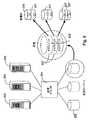
仮想ターゲットを供給する例が、図10a−dを参照して与えられる。図10aを参照すると、スイッチに接続された全部で6つのLU―LU1、LU2、LU3、LU4、LU5、LU6―を有する物理的装置があり、全てが2つのイニシエーターX及びYにアクセス可能なプール「X−Yユーザ・プール」中に置かれていると仮定する。もし、イニシエーターXが2つの仮想ターゲットを要求すると、1つの状況では、LUは仮想ターゲットVT1及びVT2を形成するために供給される。ここでは、VT1はエクステントとしてLU1−3を含み、VT2はエクステントとしてLU4−6を含み、VT1及びVT2は共にサーバーXユーザ・ドメイン中に置かれて、図10bに示すようにサーバーXが両方の仮想ターゲットにアクセスすることを可能にする。サーバーYは、Yユーザ・ドメイン中に仮想ターゲットが置かれていないため、VT1又はVT2のいずれにもアクセスしない。代替的に、図10cを参照すると、もし、サーバーX及びサーバーYが共に1つの仮想ターゲットを要求すると、前と同様にVT1及びVT2が供給されるが、VT1がサーバーXのユーザ・ドメインに置かれ、一方、VT2がサーバーYのユーザ・ドメインに置かれる。 An example of supplying a virtual target is given with reference to FIGS. 10a-d. Referring to FIG. 10a, there is a physical device with a total of six LU-LU1, LU2, LU3, LU4, LU5, LU6- connected to the switch, all accessible to two initiators X and Y Assume that it is located in the pool “XY User Pool”. If initiator X requests two virtual targets, in one situation the LU is provisioned to form virtual targets VT1 and VT2. Here, VT1 includes LU1-3 as extents, VT2 includes LU4-6 as extents, VT1 and VT2 are both located in the server X user domain, and server X is both in the server X as shown in FIG. Allows access to virtual targets. Server Y does not access either VT1 or VT2 because no virtual target is located in the Y user domain. Alternatively, referring to FIG. 10c, if both server X and server Y request one virtual target, VT1 and VT2 are provided as before, but VT1 is placed in the user domain of server X. Meanwhile, VT2 is placed in the user domain of server Y.
もし、代りに、Yがミラーされた仮想ターゲットMを要求すると、VT1及びVT2が仮想ターゲットMのメンバーとして生成される。VT1及びVT2はスイッチのノー・ドメイン中に置かれる。しかし、図10dに示すように、MはYにアクセス可能とされる。Mのメンバーとして、VT1及びVT2は独立にはアクセス可能ではない。 If instead Y requests a mirrored virtual target M, VT1 and VT2 are created as members of the virtual target M. VT1 and VT2 are placed in the no domain of the switch. However, as shown in FIG. 10d, M can access Y. As members of M, VT1 and VT2 are not independently accessible.
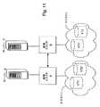
本発明のいくつかの実施の形態では、1つのスイッチへ結合された装置と仮想ターゲットがイニシエーターにアクセス可能であるだけでなく、別のスイッチに供給された仮想ターゲットも同様にアクセス可能である。図11を参照すると、サーバーXがスイッチAに結合され、そしてサーバーYがスイッチBに結合されている。VT1がスイッチA中のサーバーXのドメインの一部として供給され、VT2がスイッチB中のサーバーYのドメインの一部として供給される。さらに、スイッチBがスイッチAへのイニシエーターとして供給され、スイッチAがスイッチBへのイニシエーターとして供給される。このようにして、スイッチAはスイッチBを経由してVT2にアクセスでき、スイッチBはスイッチAを経由してVT1にアクセスできる。従って、スイッチBを経由してアクセスされるためここではVT1’として呼ばれるVT1をサーバーYの領域中に含むことができ、ここではVT2’として呼ばれるVT2をサーバーYの領域中に含むことができる(物理的装置のLUは一時に1つのプールのみに属することができるが、仮想ターゲットは一時に1つのドメインよりも多くに属することができる)。XがVT2にアクセスする時、スイッチBはスイッチAをイニシエーターとして見る。同様に、YがVT1にアクセスする時、スイッチAはスイッチBをイニシエーターとして見る。1つの実施の形態では、管理者はスイッチBの選択された資源を他のスイッチ、例えば、スイッチA、又はその逆、に利用可能としてもよい。 In some embodiments of the invention, not only devices and virtual targets coupled to one switch are accessible to the initiator, but virtual targets supplied to another switch are also accessible. . Referring to FIG. 11, server X is coupled to switch A and server Y is coupled to switch B. VT1 is supplied as part of the domain of server X in switch A, and VT2 is supplied as part of the domain of server Y in switch B. Further, switch B is supplied as an initiator to switch A, and switch A is supplied as an initiator to switch B. In this way, switch A can access VT2 via switch B, and switch B can access VT1 via switch A. Thus, because it is accessed via switch B, VT1 referred to herein as VT1 ′ can be included in the area of server Y, and VT2 referred to herein as VT2 ′ can be included in the area of server Y ( A physical device LU can belong to only one pool at a time, but a virtual target can belong to more than one domain at a time). When X accesses VT2, switch B sees switch A as an initiator. Similarly, when Y accesses VT1, switch A sees switch B as an initiator. In one embodiment, the administrator may make the selected resource of switch B available to other switches, eg, switch A or vice versa.
SLAの定義
本発明の1つの実施の形態では、イニシエーターによる仮想ターゲットへのアクセスが、ユーザにより選択されたQoSポリシーがその一部であるSLAに従って提供される。以下の表6に1つの実施の形態でユーザによりSLAのために選択できるいくつかのパラメータの例が示される。
SLA Definition In one embodiment of the present invention, access to a virtual target by an initiator is provided according to an SLA that is part of a QoS policy selected by the user. Table 6 below shows examples of some parameters that can be selected for the SLA by the user in one embodiment.
表4
ユーザがSLAと一致する時、ユーザはサービスの品質(QoS)ポリシーも選択する。上述したように、1つの実施の形態では、QoSポリシーは一般的に仮想ターゲット(供給されるような)、イニシエーター接続(供給されるような)、及びユーザ・ドメインにより定義される。従って、上の表4を再び参照し、表中の最初の3つの項目、「イニシエーターのID」、「仮想ターゲットのID」及び「ユーザ・ドメインのID」は、これらの項目が供給されるとイニシエーター接続及び仮想ターゲットの属性が定義されるため、本質的にQoSポリシーを記述する。例えば、イニシエーター接続のための最小及び最大帯域幅は、既に識別されている(表2及び3を参照)。ユーザ・ドメインはポリシーの定義を補助する。例えば、イニシエーター接続又は仮想ターゲット接続がより遅いかどうかを決定し、そして、QoSを2つの内のより遅い方へ強制する。もちろん、上述したように、ユーザ・ドメインは全ての実施の形態で必要でないであろう。同様に、他の実施の形態は上の表4に示されたものより多い、少ない、又は異なるパラメータを使用してSLAを定義してよい。 When the user matches the SLA, the user also selects a quality of service (QoS) policy. As described above, in one embodiment, a QoS policy is generally defined by a virtual target (as provisioned), an initiator connection (as provisioned), and a user domain. Therefore, referring again to Table 4 above, the first three items in the table, “Initiator ID”, “Virtual Target ID” and “User Domain ID”, are supplied with these items. Since the attributes of the initiator connection and the virtual target are defined, the QoS policy is essentially described. For example, minimum and maximum bandwidths for initiator connections have already been identified (see Tables 2 and 3). User domains help define policies. For example, determine if the initiator connection or virtual target connection is slower and force QoS to the slower of the two. Of course, as mentioned above, a user domain may not be required in all embodiments. Similarly, other embodiments may define SLA using more, fewer, or different parameters than those shown in Table 4 above.
図12
図12は、1つの実施の形態で、QoSを提供できるように、仮想ターゲットと接続を供給するステップを要約する。図示されるように、本発明の1つの実施の形態によると、スイッチは、ステップ1202で、スイッチと関連した物理的装置の特性を発見して決定する。そして、スイッチは、ステップ1204で、これらの装置を分類して、これらの装置を特定の記憶プールに関連付ける。スイッチは、ステップ1208で、イニシエーター接続のための情報を受信して、ステップ1210で、接続を供給し、SCCデータベース中にオブジェクトを生成する。また、スイッチは、ステップ1212で、仮想ターゲットのためのパラメータを受信して、ステップ1214で、これらのパラメータに従い仮想ターゲットを供給し、もし、資源が利用可能ならば、SCCデータベース内にオブジェクトを生成する。ステップ1208−1214は、どんな順番でも実行でき、図12に示された順番は例示のみである。ステップ1216で、仮想ターゲットが供給された後、ユーザ・ドメインが生成されて、仮想ターゲットがユーザ・ドメインに置かれるか、又は、仮想ターゲットは既存のユーザ・ドメイン中に置かれる。また、ユーザは前に供給された仮想ターゲットにアクセスを試みることができる(従って、ステップ1214は全ての接続については必要ではないであろう)。最後に、ステップ1218で、本発明の実施の形態によると、スイッチは、SLA/QoSパラメータを受信する。FIG.
FIG. 12 summarizes the steps of providing virtual targets and connections so that QoS can be provided in one embodiment. As shown, according to one embodiment of the present invention, the switch discovers and determines the characteristics of the physical device associated with the switch at
オブジェクト
上述したように、各仮想ターゲット、各イニシエーター接続、及び各物理的装置は、それぞれのエンティテイについてオブジェクト中に含まれた情報によりSCCデータベース内で識別される。各仮想ターゲット・オブジェクト及び物理的ターゲット・オブジェクトは、それを構成するLU又はエクステントのリストを含む。仮想ターゲット・オブジェクトの一例は、本発明の1つの実施の形態では、次の情報を含む。Object As described above, each virtual target, each initiator connection, and each physical device is identified in the SCC database by information contained in the object for each entity. Each virtual target object and physical target object includes a list of LUs or extents that compose it. An example of a virtual target object includes the following information in one embodiment of the present invention:
・エンティテイ・タイプ
・エンティテイ識別子
・IPアドレス管理
・時間スタンプ及びフラグ
・ポート
・ドメイン情報
・SCNビットマップ
・容量と質問情報
・エクステントの数
・エクステントのリスト
・エクステント・ロケーター
・仮想モード・ページ
・サービスの品質のポリシー(例えば、表4の最初の3つの項目)
・統計−使用、エラー、及び特性データ
・SLA識別子
物理的ターゲット(又は、LU)オブジェクトは同様な情報を含んでよい。-Entity type-Entity identifier-IP address management-Time stamp and flag-Port-Domain information-SCN bitmap-Capacity and query information-Number of extents-List of extents-Extent locator-Virtual mode page-Service Quality policy (for example, the first three items in Table 4)
Statistics-usage, error, and characteristic data SLA identifier physical target (or LU) objects may contain similar information.
オブジェクト中、「エンティテイ・タイプ」はエンティテイが仮想ターゲット又は物理的ターゲットかどうかを識別する。「エンティテイ識別子」は、1つの実施の形態では、WWUIであり、いくつかの実施の形態では、ユーザにより生成される。「IPアドレス管理」は、エンティテイ、例えば、管理ステーションがそれにより構成される装置のアドレスを示す。例えば、仮想ターゲットは、本発明の実施の形態ではSCCを通じてアクセスされる管理ステーションにより構成される。 In the object, “entity type” identifies whether the entity is a virtual target or a physical target. An “entity identifier” is a WWUI in one embodiment, and in some embodiments is generated by a user. “IP address management” indicates an address of an entity, for example, a device constituted by the management station. For example, the virtual target is configured by a management station accessed through the SCC in the embodiment of the present invention.
「時間スタンプ及びフラグ」は仮想ターゲット又は他のエンティテイが生成され又は変更された時間などの事象を追跡するのに使用される。フラグは、仮想ターゲット中のデータのコピーなど、進行中の事象又はさまざまなサービスを指示するために使用される。「ポート」は、それを通じてLUがアクセスできるポートのリストを含み、ポート名とラインカード数、TCP/IPアドレス又はファイバ・チャンネル24ビット・アドレス、及び、ポートがエンティテイのための一次的又は二次的ポートであるかどうかに関する情報を含む。 “Time stamps and flags” are used to track events such as the time a virtual target or other entity was created or modified. Flags are used to indicate ongoing events or various services, such as a copy of data in a virtual target. “Port” contains a list of ports through which the LU can access, port name and number of line cards, TCP / IP address or Fiber Channel 24-bit address, and primary or secondary port for entity Information about whether it is a static port.
「ドメイン情報」は仮想ターゲット又はエンティテイが属する記憶ドメイン又はプールを含む。「SCNビットマップ」は仮想ターゲットのためのシステム変更通知を指示する。「容量と質問情報」は仮想又は物理的ターゲットがどれだけ大きいかを指示し、及び、装置ベンダーにより通常提供される質問情報を含む。例えば、物理的装置についての質問情報はしばしばその製造者を識別する。仮想ターゲットについての質問情報はしばしばその仮想ターゲットを生成したスイッチを識別する。 “Domain information” includes the storage domain or pool to which the virtual target or entity belongs. The “SCN bitmap” indicates system change notification for the virtual target. “Capacity and question information” indicates how large the virtual or physical target is, and includes question information normally provided by the device vendor. For example, query information about a physical device often identifies its manufacturer. Query information about a virtual target often identifies the switch that created the virtual target.
物理的装置の各LUは、仮想ターゲットを形成するために使用されるエクステントと呼ばれる記憶空間の隣接した1つ又は複数の部分からなる。従って、「エクステントの数」はどれだけの数のエクステントが仮想ターゲットを形成するかを識別する。「エクステントのリスト」は、各エクステントを1つの実施の形態ではオフセット及び大きさにより識別する。例えば、3つのエクステントからなる10GB仮想ターゲットは、表5に示すように「エクステントのリスト」内でエクステントを識別してよい。 Each LU of a physical device consists of one or more adjacent portions of storage space called extents used to form a virtual target. Thus, the “number of extents” identifies how many extents form a virtual target. The “extent list” identifies each extent by offset and size in one embodiment. For example, a 10 GB virtual target composed of three extents may identify extents in an “extent list” as shown in Table 5.
表5
「エクステント・ロケーター」は、正確にエクステントがどこに位置するか、すなわち、どの物理的装置上にあるかを識別する。例えば、上記の10GB、3エクステント仮想ターゲットは以下のエクステント・ロケーターを持つてもよい。 The “extent locator” identifies exactly where the extent is located, ie on which physical device. For example, the above 10 GB, 3 extent virtual target may have the following extent locators:
表6
表5及び表6の両方を使用したこの例では、仮想ターゲットの第1エクステントは、オフセット5GB(表6)で開始して2GB(表5)まで延びる物理的装置2(表6)にマップされていると決定できる。第2エクステント(表5)は、オフセット3GB(表6)で開始して5GB(表5)まで延びる物理的装置1(表6)にマップされている。最後に、第3エクステントは、オフセット15GB(表6)で開始して3GB(表5)まで延びる物理的装置3(表6)にマップされている。 In this example using both Table 5 and Table 6, the first extent of the virtual target is mapped to physical device 2 (Table 6) starting at offset 5 GB (Table 6) and extending to 2 GB (Table 5). Can be determined. The second extent (Table 5) is mapped to physical device 1 (Table 6) starting at offset 3 GB (Table 6) and extending to 5 GB (Table 5). Finally, the third extent is mapped to physical device 3 (Table 6) starting at offset 15 GB (Table 6) and extending to 3 GB (Table 5).
もし、いくつかの実施の形態で、仮想ターゲットがミラーされると、ミラーされた仮想ターゲットの各メンバーは、エクステント・ロケーターは異なるが、同一のエクステント・リストを持つ。 If, in some embodiments, a virtual target is mirrored, each member of the mirrored virtual target has the same extent list, although the extent locators are different.
「仮想モードページ」は、当業者には理解されるように、SCSI命令中にしばしば見られるモードページを識別する。この情報はブロック転送大きさ、直接データ支援、又はアプリケーション・ソフトウェアがSCSIモードページ命令により設定できそして検索できるどんな独特な情報を含む。 A “virtual mode page” identifies a mode page often found in SCSI instructions, as will be appreciated by those skilled in the art. This information includes block transfer size, direct data support, or any unique information that application software can set and retrieve with SCSI mode page instructions.
「サービスの品質のポリシー」は、仮想ターゲットのサービスの特性を決定し、仮想ターゲットが供給される時に選択される。1つの実施の形態では、サービスの品質のポリシーは、表4の最初の3つの項目中に見られる識別子を使用して定義される。 The “quality of service policy” determines the characteristics of the service of the virtual target and is selected when the virtual target is provisioned. In one embodiment, the quality of service policy is defined using the identifiers found in the first three items of Table 4.
「統計」は、本発明の1つの実施の形態ではスイッチにより仮想ターゲットの実行時に収集される。これらは、本発明の1つの実施の形態では、使用、エラー。及び性能データを含み、以下にさらに説明される。
「SLA識別子」は、SLAに関する情報についてのSLAオブジェクトを識別する。“Statistics” are collected during the execution of the virtual target by the switch in one embodiment of the invention. These are used, error, in one embodiment of the present invention. And performance data, as further described below.
“SLA identifier” identifies an SLA object for information about the SLA.
統計
本発明の実施の形態によるスイッチは統計も収集する。1つの実施の形態では、1つのイニシエーターから1つの仮想ターゲットへの各接続に対して、以下の情報がイニシエーターに接続するラインカードのSPUにより収集される。Statistics The switch according to an embodiment of the present invention also collects statistics. In one embodiment, for each connection from one initiator to one virtual target, the following information is collected by the SPU of the line card that connects to the initiator.
1.全読み取りアクセス(読み取り要求数)
2.蓄積された読み取り転送バイト(記憶から読み取られた全バイト数)
3.蓄積された読み取り応答時間(要求の受け取りから応答を得るまでの時間)
4.全書込みアクセス(書込み要求数)
5.蓄積された書込み転送バイト
6.蓄積された書込み応答時間
7.蓄積された回復可能エラー
8.蓄積された回復不可能エラー1. Full read access (number of read requests)
2. Accumulated read transfer bytes (total bytes read from storage)
3. Accumulated read response time (time from receipt of request to response)
4). All write access (number of write requests)
5. Accumulated write transfer bytes 6. 6. Accumulated write response time Accumulated recoverable errors 8. Accumulated unrecoverable errors
各ラインカード上のCPUは、周期的にSPUから統計を要求する。SPUはデータを戻すことにより応答する。そして、SPUはデータをゼロにリセットして収集を開始する。 The CPU on each line card periodically requests statistics from the SPU. The SPU responds by returning data. The SPU then resets the data to zero and starts collecting.
収集されたデータに基づいて、CPUは以下の統計を維持する。
1.平均読み取りアクセス速度
2.最大読み取りアクセス速度
3.平均読み取り転送速度
4.最大読み取り転送速度
5.最小読み取り応答時間
6.平均読み取り応答時間
7.最大読み取り応答時間
8.平均書込みアクセス速度
9.最大書込みアクセス速度
10.平均書込み転送速度
11.最大書込み転送速度
12.最小書込み応答時間
13.平均書込み応答時間
14.最大書込み応答時間
15.十億の要求当たりの回復可能エラー
16.十億の要求当たりの回復不可能エラーBased on the collected data, the CPU maintains the following statistics:
1. 1. Average read access speed 2. Maximum read access speed Average read transfer rate 4. Maximum read transfer rate 5. Minimum read response time 6. Average read response time Maximum read response time 8. 8. Average write access speed Maximum write access speed 10. Average write transfer rate 11. Maximum
1つの実施の形態ではある所定の時間間隔後に、CPUはSCCへ統計を転送して、関連VTD(SPU内に記憶されている)を更新する。別の実施の形態では、SCCはCPUから統計を要求し、CPUはそれをSCCへ提供する。いくつかの実施の形態では、SCCはまた、データが正確で過剰に蓄積されないように、その統計を周期的、例えば、週単位でリセットする。 In one embodiment, after a certain time interval, the CPU transfers statistics to the SCC and updates the associated VTD (stored in the SPU). In another embodiment, the SCC requests statistics from the CPU, which provides it to the SCC. In some embodiments, the SCC also resets its statistics periodically, eg, weekly, so that the data is accurate and does not accumulate excessively.
QoSの実行
1つの実施の形態では、イニシエーター接続帯域幅の最小パーセンテイジは、QoSにより保証される。従って、このような実施の形態で、複数のイニシエーターが単一のポート上で供給される時、全てのイニシエーターの全ての最小帯域幅の合計は100%に等しいか又はそれより少なければならない。対照的に、最大パーセンテイジは、同じ接続上で他の競合するユーザが存在しない時に接続の可能な使用を与える。従って、全てのイニシエーターの帯域幅の最大パーセンテイジの和は、接続の帯域幅100%を超えることができる。この場合、定義されたスイッチング優先度(表2参照)が、どのイニシエーターが予定の最初を獲得するかを決定する。QoS Implementation In one embodiment, the minimum percentage of initiator connection bandwidth is guaranteed by QoS. Thus, in such an embodiment, when multiple initiators are served on a single port, the sum of all minimum bandwidths of all initiators must be less than or equal to 100%. . In contrast, maximum percentage gives a possible use of the connection when there are no other competing users on the same connection. Therefore, the sum of the maximum percentages of the bandwidth of all initiators can exceed 100% of the connection bandwidth. In this case, the defined switching priority (see Table 2) determines which initiator gets the first in the schedule.
従来の接続ネットワークでは(記憶ネットワークとは反対に)、QoSはユーザが支払った接続のデータ帯域幅のパーセンテイジを獲得することを保証するために使用される。それはオーディオ及びビデオなどの時間敏感データが、送信前に予約されたデータ帯域幅を交渉するか又は時間敏感送信を渋滞した状況でより高い優先度を与えるかのいずれかにより、許容できる中断のみを経験することを可能にする。QoSは、パケットを落とす出費によってスイッチング・トラフイックを優先付けることでさえ実行される。 In a traditional connection network (as opposed to a storage network), QoS is used to ensure that the data bandwidth percentage of the connection paid by the user is obtained. It only allows acceptable interruptions, either by negotiating the reserved data bandwidth prior to transmission, or giving higher priority in situations where time sensitive transmission is congested, such as audio and video. Allows to experience. QoS is even performed by prioritizing switching traffic with the expense of dropping packets.
しかし、要求が1つ又は複数のパケットを含むことができる従来のネットワーク通信システムとは異なり、記憶システムの要求を落とすことは許容できない。1つの実施の形態では、要求が完了するまで、イニシエーターからターゲットへ送受信される全てのパケットを含む。例えば、iSCSI命令PDU、iSCSIR2T、iSCSI書込みデータPDU、及びiSCSI応答PDUは、単一の要求を形成する。本発明の実施の形態による記憶スイッチに対しては、1つの実施の形態では、データ帯域幅が秒当たりの要求数に要求の平均転送大きさを掛算して計算される。例えば、秒当たり1000要求で、平均転送大きさが8KBの場合、記憶装置の帯域幅は、8MB/秒(又は、80Mb/秒)である。しかし、スイッチは要求の平均転送大きさの制御を持たないため、記憶アクセスについてのQoSを実行することは秒当たり同時に許容される要求数を制御することになる。従って、もし、イニシエーターから多すぎる要求が送信されると、同時的要求の数は減少されなければならない。1つの実施の形態では、最悪のケースでは、一時に1つの要求のみがイニシエーターから送られることができる。 However, unlike conventional network communication systems where the request can include one or more packets, dropping the storage system request is unacceptable. In one embodiment, it includes all packets sent and received from the initiator to the target until the request is completed. For example, an iSCSI command PDU, an iSCSI IR2T, an iSCSI write data PDU, and an iSCSI response PDU form a single request. For a storage switch according to an embodiment of the present invention, in one embodiment, the data bandwidth is calculated by multiplying the number of requests per second by the average transfer size of the requests. For example, at 1000 requests per second and an average transfer size of 8 KB, the bandwidth of the storage device is 8 MB / second (or 80 Mb / second). However, since the switch does not have control of the average transfer size of requests, performing QoS for storage access controls the number of requests allowed simultaneously per second. Therefore, if too many requests are sent from the initiator, the number of simultaneous requests must be reduced. In one embodiment, in the worst case, only one request can be sent from the initiator at a time.
仮想ターゲットは、最大数の同時的要求を支援する。複数の仮想ターゲットをアクセスするイニシエーターは、それがアクセスしている全ての仮想ターゲットについての要求の最大数の和に等しい要求の最大数を送信できる。しかし、複数のイニシエーターが1つ又は複数の仮想ターゲットを共有する時、利用可能な要求の最大数は、帯域幅の最小パーセンテイジのそれぞれのQoSパラメータに従って比例配分されて、イニシエーター間で共有される。例えば、もし、2つのイニシエーターが100の同時的要求を収容できる仮想ターゲットへのアクセスを共有していて、そして、イニシエーター1が帯域幅の最小の70%を得て、イニシエーター2が帯域幅の最小の30%を得ている場合、最初は、イニシエーター1は70要求を送信でき、イニシエーター2は30要求を送信できる。しかし、各イニシエーターはそれ自身の要求大きさを持つから、大きな要求大きさはより大きな帯域幅を消費して、より小さな転送大きさの他のイニシエーターを締め出す。従って、以下に説明するように、1つの実施の形態では、帯域幅の範囲を保証するために各イニシエーターによる可能な要求の調節が実行される。 A virtual target supports the maximum number of simultaneous requests. An initiator accessing multiple virtual targets can send a maximum number of requests equal to the sum of the maximum number of requests for all virtual targets it is accessing. However, when multiple initiators share one or more virtual targets, the maximum number of available requests is proportionally distributed according to the respective QoS parameters of the minimum bandwidth percentage and shared among the initiators. Is done. For example, if two initiators share access to a virtual target that can accommodate 100 simultaneous requests, and
入場及び出場ラインカード内のトラフイック管理(TM)608(図6)は、異なる接続の転送帯域幅を監視する。また、TMは、QoSパラメータに基づいて配達を予定する。従って、TMは各共有された接続がその最小帯域幅を得て、最大帯域幅により制限されることを保証する。換言すると、TMは各接続が指定された範囲内にあることを保証する。そのようにするため、1つの実施の形態では、パケットがTMバッフア612内で蓄積される時、このような蓄積はイニシエーターがその限界に到達したことを指示する。TMは、違反したイニシエーターにその接続を遅くするように指示する制御メッセージをSPUへ送信する。このようなメッセージを受信した後、SPUは違反したイニシエーターへ許容される要求の数を減らして、一方、より少ない持分を受け取っているイニシエーターへ許容される要求の数を増加する。1つの実施の形態では、サーバーへの利用可能な要求の数の通知は、iSCSIPDU中のMaxCmdSNフィールドで行われる。 Traffic management (TM) 608 (FIG. 6) in the entry and exit line cards monitors the transfer bandwidth of the different connections. The TM also schedules delivery based on QoS parameters. Thus, TM ensures that each shared connection gets its minimum bandwidth and is limited by the maximum bandwidth. In other words, TM ensures that each connection is within the specified range. To do so, in one embodiment, when a packet is accumulated in the
例えば、イニシエーターA及びイニシエーターBの両方が、それらの最小帯域幅50%として共有されたイニシエーター接続を持つ。100KBの転送大きさを使用して、イニシエーターAは秒当たり800要求を送信し、よって、接続上で秒当たり80MBの帯域幅を得ている。転送大きさ4Kを使用して、イニシエーターBは秒当たり2000要求を送信するが、たった秒当たり8MBの帯域幅を得る。従って、もし、イニシエーターAに許された最大帯域幅が秒当たり70MBである場合、スイッチは秒当たり70MBを得るためにイニシエーターAからの要求数を秒当たり700の要求に減少しなければならない。従って、入場トラフイック・マネージャ608iは、入場SPUに、イニシエーターAがその最大を超過して、パケットがバッフア612iに蓄積していることを報告する。SPUは、そのメッセージを受け取ると、Aへの可能な要求の数を減少してそしてBへのそれらを増加する。よって、イニシエーターBはより多くの要求を接続上に送信できる。イニシエーターがその最小パーセンテイジ帯域幅に到達してもその可能な要求の使用を最大化しない時、調節は必要でないことに注意する。さらに、イニシエーターBが現在、接続の50%を要求していないため、イニシエーターAはその最大の可能な帯域幅まで使用することが自由である(しかし、超過しない)。For example, both initiator A and initiator B have initiator connections shared as their minimum bandwidth of 50%. Using a 100 KB transfer size, initiator A sends 800 requests per second, thus gaining 80 MB of bandwidth per second on the connection. Using a transfer size of 4K, initiator B sends 2000 requests per second, but gets a bandwidth of only 8 MB per second. Therefore, if the maximum bandwidth allowed for initiator A is 70 MB per second, the switch must reduce the number of requests from initiator A to 700 requests per second to obtain 70 MB per second. . Accordingly,
同様に、もし、2つの異なる接続上の2つのイニシエーターが単一の仮想ターゲットを共有している場合、各イニシエーターに対して比例分割された要求数は、出場ラインカード上のTM608eが2つのイニシエーター間の不当な帯域幅の使用を検知する時、調節される。それはこのような不当な帯域幅使用を、違反したイニシエーターがパケットをバッフア612eに蓄積する時に発見する。Similarly, if, when the two initiator on two different connections share a single virtual target, the number of requests that have been proportionally divided for each initiator, the TM608e on participation Line Card Adjusted when detecting undue bandwidth usage between two initiators. It discovers such unfair bandwidth usage, when offending initiator accumulates a packet to
接続が共有されていないで、物理的記憶装置自身がビジーとなって渋滞を発生した時、出場TM608eはPPUにパケットがバッフア612eに蓄積していることを知らせる。再び、SPUはイニシエーターを遅くするために、可能な要求の数を減少する。In connection is not shared, when the physical storage device itself occurs congestion becomes busy, played TM608e informs that the packet to PPU is accumulated in
また、スイッチはイニシエーターと記憶装置との間の帯域幅を一致する。例えば、最小100%の1Gb接続を持つイニシエーターを支援するため、他の仮想ターゲットは記憶接続上に割当てることができない。しかし、イニシエーターが接続の50%帯域幅のみを要求する時、残りの50%は別の仮想ターゲットに割当てることができる。 The switch also matches the bandwidth between the initiator and the storage device. For example, to support an initiator with a minimum 100% 1 Gb connection, other virtual targets cannot be allocated on the storage connection. However, when the initiator requests only 50% bandwidth of the connection, the remaining 50% can be allocated to another virtual target.
最後に、他の全てが等しい時、接続の優先度が、どの命令がラインカードのスイッチ・トラフイック・マネージャにより最初に配達されかを決定する。
以下の表7が、1つの実施の形態についてここで説明されたQoS実行を要約する。Finally, when all else is equal, the priority of the connection determines which instructions are first delivered by the line card switch traffic manager.
Table 7 below summarizes the QoS implementation described herein for one embodiment.
表7
第1の状態において、イニシエーター入場ポートは共有されずそしてターゲット出場ポートは共有されない場合、渋滞はしばしばビジーな物理的ターゲット装置により発生されて一般に出場バッフア閾値が超過する時に検出される(出場バッフアは許容ポイント超えてバックアップされる)。従って、適当な動作はイニシエーターからの可能な要求数を減少することである。 In the first state, if the initiator entry port is not shared and the target entry port is not shared, traffic congestion is often generated by a busy physical target device and is generally detected when the entry buffer threshold is exceeded (entry buffer). Will be backed up beyond the tolerance point). Thus, proper operation is to reduce the number of possible requests from the initiator.
第2の状態において、共有されたイニシエーター入場ポートは、ターゲット出場ポートが共有されないように、異なるポート上の異なるターゲットにアクセスするイニシエーターにより共有される。イニシエーターの1つにより使用される過剰な帯域幅は、閾値が超過されたかどうかを決定することにより入場バッフア内で検出されて、バッフアが許容ポイントを超えてバックアップするようにする。適当な動作は、違反イニシエーターからの可能な要求数を減少することである。 In the second state, the shared initiator entry port is shared by initiators accessing different targets on different ports so that the target entry port is not shared. Excess bandwidth used by one of the initiators is detected in the admission buffer by determining whether a threshold has been exceeded, allowing the buffer to back up beyond an acceptable point. A reasonable action is to reduce the number of possible requests from violating initiators.
第3の状態において、イニシエーター入場ポートは共有されないが、ターゲット出場ポートは共有されて、同じターゲットが異なるポートから異なるイニシエーターによりアクセスされることを指示する。イニシエーターの1つによる過剰な要求数によって発生する過剰な帯域幅の使用は、出場バッフア内で検出される。適当な動作は、異なるイニシエーターからの可能な要求数を再分配することである。例えば、1つのイニシエーターの可能な要求数を減少し、一方、他のイニシエーターの要求数を増加する。 In the third state, the initiator entry port is not shared, but the target entry port is shared, indicating that the same target is accessed by different initiators from different ports. Excess bandwidth usage caused by an excessive number of requests by one of the initiators is detected in the entry buffer. A suitable operation is to redistribute the possible number of requests from different initiators. For example, reducing the number of possible requests for one initiator while increasing the number of requests for another initiator.
第4の状態において、イニシエーター入場ポートは共有されないが、ターゲット出場ポートは共有される。しかし、この場合、異なるターゲットは異なるイニシエーターにより同じ出場ポート上でアクセスされる。このような場合、過剰な帯域幅が各ターゲットが接続帯域幅のパーセンテイジを与えられている出場バッフア内で検出される。このような場合で取るべき適当な動作は、違反イニシエーターへの可能な要求数を減少することである。 In the fourth state, the initiator entry port is not shared, but the target entry port is shared. However, in this case, different targets are accessed on the same entry port by different initiators. In such a case, excess bandwidth is detected in the entry buffer where each target is given a percentage of the connection bandwidth. An appropriate action to take in such a case is to reduce the number of possible requests to the violating initiator.
最後に、第5の状態は共有されたイニシエーター入場ポート及び共有されたターゲット出場ポートを示す。このような状態では、二段階決定が存在する。第1は各仮想ターゲットが帯域幅のその割当てられたパーセンテイジを獲得することを保証し、そして、第2に異なるイニシエーターへ可能な要求数を比例配分することである。このような決定はバッフア閾値が超過したかどうか見ることにより、入場及び出場バッフアの両方で行われる。適当な動作は、上記の4つの状態で行われたように各仮想ターゲットを別個に取り扱い、必要により要求数を減少することである。
理解されるように、表7は説明のためであり、別の実施の形態では、QoSを実行するために別の動作を行うことができ、そして上述にない他の状態が発生できる。Finally, the fifth state shows a shared initiator entry port and a shared target entry port. In such a situation, a two-stage decision exists. The first is to ensure that each virtual target acquires its assigned percentage of bandwidth, and second, to prorate the number of possible requests to different initiators. Such a determination is made at both entry and exit buffers by looking at whether the buffer threshold has been exceeded. A reasonable operation is to treat each virtual target separately as done in the above four states, reducing the number of requests if necessary.
As will be appreciated, Table 7 is for illustrative purposes, and in other embodiments, other actions can be performed to perform QoS, and other conditions not described above can occur.
負荷平衡
1つの実施の形態では、負荷平衡が使用され、ターゲット装置への複数の経路が利用可能な時、より速くターゲット装置に到達するために経路が動的に選択されることにより発生する。負荷平衡は、スイッチ内の各ポート上で、各要求に対して、各ポート上でのSPU処理パワーを使用することにより動的に実行される(固定された時間間隔で、静的にするのとは反対に)。Load Balancing In one embodiment, load balancing is used and occurs when a path is dynamically selected to reach the target device faster when multiple paths to the target device are available. Load balancing is performed dynamically on each port in the switch for each request by using the SPU processing power on each port (to make it static at fixed time intervals). The opposite).
フェイルオーバーは負荷平衡の特別な場合であり、本発明のいくつかの実施の形態で使用される。フェイルオーバーはミラーされたターゲットの1つのメンバーが利用不可能になった時、又は、複数の経路によりアクセス可能なターゲットへの1つの経路が使用不可能になった時に発生し、いずれの場合、他のメンバーがアクセスされるか又は他の経路が利用される。 Failover is a special case of load balancing and is used in some embodiments of the present invention. Failover occurs when one member of a mirrored target becomes unavailable or when one path to a target that is accessible by multiple paths becomes unavailable, Other members are accessed or other routes are utilized.
本発明の実施の形態によるスイッチにおいて、スイッチは負荷平衡に関して2つの異なるタイプの動作を実行する。 In a switch according to an embodiment of the present invention, the switch performs two different types of operations with respect to load balancing.
1.図13bを参照すると、もし、仮想ターゲットがミラーされている場合、スイッチはイニシエーターの読出し要求を、最短の平均応答時間を持つミラーされた仮想ターゲットのメンバーを選択することにより、ミラーされたメンバーの1つへ送る。 1. Referring to FIG. 13b, if the virtual target is mirrored, the switch requests the initiator read request to select the mirrored virtual target member with the shortest average response time. Send to one of the
2.図13aを参照すると、もし、LUへ複数の経路が存在する場合、スイッチはLUへの要求を最短の平均応答時間を持つ経路に送信する。しかし、1つの実施の形態では、この負荷平衡は、他の実施の形態ではこのような要件は持たないが、複数の経路がターゲットLUから同じSPUへ接続されている時にのみ、実行される。 2. Referring to FIG. 13a, if there are multiple paths to an LU, the switch sends a request for the LU to the path with the shortest average response time. However, in one embodiment, this load balancing is performed only when multiple paths are connected from the target LU to the same SPU, although other embodiments do not have such a requirement.
いくつかの実施の形態では、スイッチはまた、「通過」構成を支援する。このような実施の形態では、仮想ターゲットは物理的ターゲット自身であり、そして全ての命令は解釈無しに、例えば、仮想化又は翻訳無しに、スイッチを「通過」する。このような実施の形態では、全ての負荷平衡機能はサーバー自身により処理される。 In some embodiments, the switch also supports a “pass through” configuration. In such an embodiment, the virtual target is the physical target itself and all instructions “pass through” the switch without interpretation, eg, without virtualization or translation. In such an embodiment, all load balancing functions are handled by the server itself.
さらに詳細には、負荷平衡について、上述したように収集された統計を使用して、本発明によるスイッチは、ミラーされた仮想ターゲットの各メンバーの応答時間を含む、各ターゲットの平均応答時間を追跡する。関連する統計は各VTDに記憶されて、CPUにより定期的に更新される。読取り操作の際、SPU(VTDを参照する)は最小の平均応答時間を持つ経路を選択してその経路上に要求を転送するか、又は、それは最小の平均応答時間を持つミラーされたメンバーを選択してそのメンバーへ要求を転送する。ミラーされたターゲットでは、書込みはミラーされた仮想ターゲットの全てのメンバーに対して行われるから、書込み操作に対してミラーされたメンバー間の選択は行われないことに注意する。1つの経路が他の経路に対して明確な利益がない時、又は、1つのミラーされたメンバーが他の経路に対して明確な利益がない時、命令は交互にさまざまな経路/メンバーへ送られる。 More specifically, for load balancing, using the statistics collected as described above, the switch according to the present invention tracks the average response time of each target, including the response time of each member of the mirrored virtual target. To do. Relevant statistics are stored in each VTD and updated regularly by the CPU. During a read operation, the SPU (see VTD) selects the path with the lowest average response time and forwards the request on that path, or it selects the mirrored member with the lowest average response time. Select to forward the request to that member. Note that for mirrored targets, the write is done to all members of the mirrored virtual target, so there is no selection between mirrored members for the write operation. When one route has no clear benefit over the other route, or when one mirrored member has no clear benefit over the other route, instructions are sent alternately to the various routes / members. It is done.
本発明の1つの実施の形態では、複数の同時的接続はiSCSI装置に対してのみ使用される。ファイバー・チャンネルは現在、このような複数の同時的接続を支援しない。しかし、他のプロトコルを使用する他の実施の形態もまた複数同時接続を支援する。 In one embodiment of the invention, multiple simultaneous connections are used only for iSCSI devices. Fiber Channel currently does not support such multiple simultaneous connections. However, other embodiments using other protocols also support multiple simultaneous connections.
上述の特定の実施の形態は本発明の説明の目的ためのみであり、さまざまな修正が本発明の精神と範囲から逸脱することなく当業者にできる。従って、本発明の範囲は特許請求の範囲のみにより限定される。 The specific embodiments described above are for illustrative purposes only and various modifications can be made by those skilled in the art without departing from the spirit and scope of the invention. Accordingly, the scope of the invention is limited only by the claims.
Claims (34)
Translated fromJapanese記憶ネットワーク中の記憶装置にアクセスするためのサービスの品質をイニシエーターに提供することを含み、
前記サービスの品質を提供するステップが、イニシエーターから記憶装置への要求数を制御する方法。A method for use in a storage network comprising at least one initiator and at least one storage device, comprising:
Providing the initiator with quality of service for accessing storage devices in the storage network,
The method of providing the quality of service controls the number of requests from the initiator to the storage device.
記憶ネットワーク中の記憶装置にアクセスするためのサービスの品質をイニシエーターに提供することを含み、
前記サービスの品質を提供するステップが、イニシエーターにより送信可能な同時的要求の数を調節する方法。A method for use in a storage network comprising at least one initiator and at least one storage device, comprising:
Providing the initiator with quality of service for accessing storage devices in the storage network,
Method steps of providing a quality ofthe service, to adjust the number of possible transmission simultaneous request by the initiator.
記憶ネットワーク中の記憶装置にアクセスするためのサービスの品質をイニシエーターに提供することを含み、
前記サービスの品質を提供するステップが、指定された範囲内にイニシエーターにより使用される帯域幅を維持するためにイニシエーターに可能な要求数を調節する方法。A method for use in a storage network comprising at least one initiator and at least one storage device, comprising:
Providing the initiator with quality of service for accessing storage devices in the storage network,
The method of providing quality of service adjusts the number of requests possible to an initiator to maintain the bandwidth used by the initiator within a specified range.
前記イニシエーターと前記記憶装置が共に前記スイッチと通信し、
前記スイッチが前記記憶ネットワーク中のサービスの品質を提供するステップを実行することを含む請求項1〜3の何れか1項に記載の方法。The storage network further includes a switch;
Both the initiator and the storage device communicate with the switch;
The method according toany one of claims 1 to3, comprising the step of the switch performing a step of providing a quality of service in the storage network.
(1)記憶ネットワーク中の記憶装置にアクセスするためのサービスの品質をイニシエーターに提供するステップであって、
イニシエーターが記憶装置へアクセスするための最小帯域幅を保証し、
イニシエーターにより使用される実際の帯域幅を測定し、実際の帯域幅は秒当たりの要求数にイニシエーターからの要求の平均大きさを掛算することにより測定され、
イニシエーターにより送信されることが可能な同時的要求の数を調節することを含む、当該ステップと、
(2)記憶装置にアクセスするために最大帯域幅までイニシエーターに保証するステップとを含み、
前記同時的要求の数を調節することが、実際の帯域幅が最大帯域幅を超過した時に、イニシエーターにより可能な同時的要求数を減少させる方法。A method for use in a storage network comprising at least one initiator and at least one storage device, comprising:
(1)providing an initiator with quality of service for accessing storage devices in a storage network,
Guarantees minimum bandwidth for initiators to access storage devices,
Measure the actual bandwidth used by the initiator, which is measured by multiplying the number of requests per second by the average size of requests from the initiator,
Adjusting the number of simultaneous requests that can be sent by the initiator, and
And astep for ensuring the initiator up bandwidth for access to(2) the storage device,
It said method adjusting the number of simultaneous requests, which when the actual bandwidth exceeds the maximum bandwidth, Rureduce the simultaneous number of requests allowed by initiator.
スイッチにより記憶ネットワーク内の記憶装置へアクセスするためにイニシエーターに最小帯域幅を保証し、
スイッチにより、イニシエーターにより使用される実際の帯域幅を測定し、実際の帯域幅は秒当たりの要求数にイニシエーターからの要求の平均大きさを掛算することにより測定されることを含む方法。A method for use in a storage network comprising at least one initiator, at least one storage device, and at least one switch, wherein the initiator and the storage device both communicate with the switch, comprising:
The switch guarantees a minimum bandwidth for the initiator to access the storage devices in the storage network,
Measuring the actual bandwidth used by the initiator by means of a switch, wherein the actual bandwidth is measured by multiplying the number of requests per second by the average size of requests from the initiator.
イニシエーターにより送信することが可能な同時的要求の数を減少することを含む請求項8に記載の方法。The step to adjust is
9. The method of claim8 , comprising reducing the number of simultaneous requests that can be transmitted by an initiator.
イニシエーターにより送信することが可能な同時的要求の数を増加することを含む請求項8に記載の方法。The step to adjust is
9. The method of claim8 , comprising increasing the number of simultaneous requests that can be transmitted by the initiator.
でいるかを決定することを含む請求項7に記載の方法。8. The method of claim7 , wherein measuring actual bandwidth includes determining whether the buffer includes a number of packets that exceed a specified threshold.
スイッチにより、複数の接続の各々についてそれぞれ最小帯域幅を保証し、それぞれの接続の各々は記憶ネットワーク中でスイッチを経由してそれぞれのイニシエーターからそれぞれのターゲットへの接続であり、
スイッチにより、各イニシエーターにより使用される実際の帯域幅を監視し、この実際の帯域幅はイニシエーターからの秒当たりの要求数にイニシエーターからの要求の平均大きさを掛算することにより測定され、
1つのイニシエーターにより使用される実際の帯域幅が過剰かどうかを決定し、もし、過剰ならば、スイッチにより、少なくとも1つのイニシエーターに対する可能な同時的要求の数を調節することを含む方法。A method for use in a storage network comprising a plurality of initiators, a plurality of targets, and at least one switch comprising:
A switch guarantees a minimum bandwidth for each of a plurality of connections, each of which is a connection from a respective initiator to a respective target via a switch in the storage network,
The switch monitors the actual bandwidth used by each initiator, and this actual bandwidth is measured by multiplying the number of requests per second from the initiator by the average size of requests from the initiator. ,
Determining whether the actual bandwidth used by one initiator is excessive, and if so, adjusting by a switch the number of possible simultaneous requests to at least one initiator.
記憶ネットワーク内でスイッチを経由してイニシエーターから記憶装置への接続を提供し、
スイッチにより、イニシエーターにより使用される帯域幅を指定の範囲内に維持するためにイニシエーターに許容された要求数を調節することを含む方法。A method for use in a storage system comprising at least one initiator, at least one storage device, and at least one switch, wherein both the initiator and the storage device communicate with the switch, comprising:
Provides a connection from the initiator to the storage device via a switch in the storage network,
Adjusting the number of requests allowed by the initiator to maintain the bandwidth used by the initiator within a specified range by a switch.
少なくとも1つのイニシエーター及び少なくとも1つの記憶装置を含む外部装置へ接続されるべきポートと、
帯域幅コントローラと、
を含み、
前記帯域幅が、秒当たりの要求数と要求の平均大きさとの掛算により定義されるスイッチ。A switch used in a storage network,
A port to be connected to an external device including at least one initiator and at least one storage device;
A bandwidth controller;
Including
Switchthe bandwidth, which is defined by the multiplication of the average size of the number of requests per second and the request.
前記記憶プロセッサと通信するトラフイック・マネージャと、
前記トラフイック・マネージャと通信するバッファとを含み、
もし、前記バッファ内で指定された閾値に達した場合、前記トラフイック・マネージャが前記要求コントローラを活性化するように構成され、
前記要求コントローラが、イニシエーターにより使用される帯域幅を指定された範囲内に維持するために、イニシエーターに許容される要求数を調節するように構成されているスイッチ。A storage processor including a request controller;
A traffic manager in communication with the storage processor;
A buffer in communication with the traffic manager;
If the threshold specified in the buffer is reached, the traffic manager is configured to activate the request controller;
Switchthe requesting controller, that in order to keep within the specified bandwidth used by the initiator, is configured to adjust the number of requests allowed for the initiator.
前記記憶プロセッサと通信するトラフイック・マネージャと、
前記トラフイック・マネージャと通信するバッファとを含み、
もし、前記バッファ内で指定された閾値に達した場合、前記トラフイック・マネージャが前記要求コントローラを活性化するように構成され、
帯域幅が、秒当たりの要求数と要求の平均の大きさとの掛算により定義されるスイッチ。A storage processor including a request controller;
A traffic manager in communication with the storage processor;
A buffer in communication with the traffic manager;
If the threshold specified in the buffer is reached, the traffic manager is configured to activate the request controller;
A switch whose bandwidth is defined as the number of requests per second multiplied by the average size of requests.
少なくとも1つのイニシエーターと少なくとも1つの記憶装置とを含む外部装置に接続されるべきポートと、
前記記憶ネットワーク内で、前記イニシエーターから前記記憶装置への接続についてサービスの品質を提供する手段と、を備え、
前記サービスの品質を提供する手段が、
イニシエーターに記憶装置へアクセスするための最小帯域幅を保証する手段と、
イニシエーターにより使用される実際の帯域幅を監視する手段と、この実際の帯域幅は秒当たりの要求数に要求の平均大きさを掛算することにより測定され、
イニシエーターにより使用される実際の帯域幅を、下側制限として最小帯域幅を持つ指定された範囲内に維持するため、イニシエーターにより送信されるべき可能な同時的要求の数を調節する手段と、
を含むスイッチ。A switch used for a storage network,
A port to be connected to an external device including at least one initiator and at least one storage device;
Providing quality of service for connection from the initiator to the storage device within the storage network; and
It means for providing a quality ofthe service,
Means to guarantee the minimum bandwidth for the initiator to access the storage device;
A means of monitoring the actual bandwidth used by the initiator, and this actual bandwidth is measured by multiplying the number of requests per second by the average size of the request,
Means to adjust the number of possible simultaneous requests to be sent by the initiator to maintain the actual bandwidth used by the initiator within a specified range with a minimum bandwidth as a lower limit; ,
Including switch.
記憶装置と、
イニシエーター及び記憶装置と通信するスイッチとを含み、
スイッチはバッフアと通信するトラフイック・マネージャを含み、
イニシエーターからのいくつかのパケットを含むバッフアが指定された閾値を超過した時、スイッチがイニシエーターに同時的要求の数を減少するために通知するように構成されている記憶ネットワーク。An initiator,
A storage device;
A switch that communicates with the initiator and the storage device,
The switch includes a traffic manager that communicates with the buffer,
A storage network configured to notify the initiator to reduce the number of simultaneous requests when a buffer containing a number of packets from the initiator exceeds a specified threshold.
スイッチにより、記憶ネットワーク内の記憶装置へアクセスするための最小帯域幅をイニシエーターに保証し、
スイッチにより、イニシエーターにより使用される実際の帯域幅を測定し、この実際の帯域幅はイニシエーターからの秒当たりの要求数に要求の平均大きさを掛算することにより測定される、
機械的に読取り可能な媒体。A machine-readable medium storing instructions that, when executed by a storage network switch, cause the switch to perform the following steps:
The switch guarantees the initiator minimum bandwidth to access storage devices in the storage network,
The switch measures the actual bandwidth used by the initiator, and this actual bandwidth is measured by multiplying the number of requests per second from the initiator by the average size of the request,
A machine-readable medium.
イニシエーターにより送信することが可能な同時的要求の数を減少することを含む請求項29に記載の機械的に読取り可能な媒体。The step of adjusting
30. The machine-readable medium of claim29 , including reducing the number of simultaneous requests that can be transmitted by the initiator.
イニシエーターにより送信することが可能な同時的要求の数を増加することを含む請求項29に記載の機械的に読取り可能な媒体。The step of adjusting
30. The machine readable medium of claim29 , including increasing the number of simultaneous requests that can be transmitted by the initiator.
バッフアが指定された閾値を超えてパケット数を含むかどうかを決定することを含む請求項28に記載の機械的に読取り可能な媒体。Measuring the actual bandwidth
29. The machine-readable medium of claim28 , including determining whether the buffer includes a packet number that exceeds a specified threshold.
Applications Claiming Priority (3)
| Application Number | Priority Date | Filing Date | Title |
|---|---|---|---|
| US32570401P | 2001-09-28 | 2001-09-28 | |
| US10/051,339US7421509B2 (en) | 2001-09-28 | 2002-01-18 | Enforcing quality of service in a storage network |
| PCT/US2002/030889WO2003036501A1 (en) | 2001-09-28 | 2002-09-27 | Enforcing quality of service in a storage network |
Publications (2)
| Publication Number | Publication Date |
|---|---|
| JP2005507201A JP2005507201A (en) | 2005-03-10 |
| JP4264001B2true JP4264001B2 (en) | 2009-05-13 |
Family
ID=26729318
Family Applications (1)
| Application Number | Title | Priority Date | Filing Date |
|---|---|---|---|
| JP2003538922AExpired - LifetimeJP4264001B2 (en) | 2001-09-28 | 2002-09-27 | Quality of service execution in the storage network |
Country Status (4)
| Country | Link |
|---|---|
| US (1) | US7421509B2 (en) |
| EP (1) | EP1438677A4 (en) |
| JP (1) | JP4264001B2 (en) |
| WO (1) | WO2003036501A1 (en) |
Families Citing this family (151)
| Publication number | Priority date | Publication date | Assignee | Title |
|---|---|---|---|---|
| TW576061B (en)* | 2001-08-13 | 2004-02-11 | Via Tech Inc | Device and method for load balancing of packet switching |
| US7864758B1 (en)* | 2001-09-28 | 2011-01-04 | Emc Corporation | Virtualization in a storage system |
| US20030126280A1 (en)* | 2001-12-31 | 2003-07-03 | Maxxan Systems, Inc. | XON/XOFF flow control for computer network |
| US7290277B1 (en)* | 2002-01-24 | 2007-10-30 | Avago Technologies General Ip Pte Ltd | Control of authentication data residing in a network device |
| US20030145128A1 (en)* | 2002-01-25 | 2003-07-31 | Baird Roger T. | Mapping managing devices to managed devices |
| US8260907B2 (en)* | 2002-04-04 | 2012-09-04 | Ca, Inc. | Methods, systems and computer program products for triggered data collection and correlation of status and/or state in distributed data processing systems |
| JP4704659B2 (en)* | 2002-04-26 | 2011-06-15 | 株式会社日立製作所 | Storage system control method and storage control device |
| US20030208614A1 (en)* | 2002-05-01 | 2003-11-06 | John Wilkes | System and method for enforcing system performance guarantees |
| JP3956786B2 (en)* | 2002-07-09 | 2007-08-08 | 株式会社日立製作所 | Storage device bandwidth control apparatus, method, and program |
| US7154886B2 (en)* | 2002-07-22 | 2006-12-26 | Qlogic Corporation | Method and system for primary blade selection in a multi-module fiber channel switch |
| US7230929B2 (en)* | 2002-07-22 | 2007-06-12 | Qlogic, Corporation | Method and system for dynamically assigning domain identification in a multi-module fibre channel switch |
| JP3869769B2 (en)* | 2002-07-24 | 2007-01-17 | 株式会社日立製作所 | Switching node device for storage network and access method of remote storage device |
| US8320241B2 (en) | 2002-07-30 | 2012-11-27 | Brocade Communications System, Inc. | Fibre channel network employing registered state change notifications with enhanced payload |
| US7474652B2 (en)* | 2002-07-30 | 2009-01-06 | Brocade Communications Systems, Inc. | Caching remote switch information in a fibre channel switch |
| US7334046B1 (en) | 2002-08-05 | 2008-02-19 | Qlogic, Corporation | System and method for optimizing frame routing in a network |
| US20040054943A1 (en)* | 2002-08-08 | 2004-03-18 | International Business Machines Corporation | Method and system for improving the availability of software processes utilizing configurable finite state tables |
| JP4206707B2 (en)* | 2002-08-27 | 2009-01-14 | 株式会社日立製作所 | Communication quality setting apparatus, method and program |
| US6952757B2 (en)* | 2002-08-29 | 2005-10-04 | International Business Machines Corporation | Method, system, and program for managing storage units in storage pools |
| US7397768B1 (en) | 2002-09-11 | 2008-07-08 | Qlogic, Corporation | Zone management in a multi-module fibre channel switch |
| JP2004110367A (en) | 2002-09-18 | 2004-04-08 | Hitachi Ltd | Storage device system control method, storage control device, and storage device system |
| US7640342B1 (en)* | 2002-09-27 | 2009-12-29 | Emc Corporation | System and method for determining configuration of one or more data storage systems |
| US7362717B1 (en) | 2002-10-03 | 2008-04-22 | Qlogic, Corporation | Method and system for using distributed name servers in multi-module fibre channel switches |
| US6886141B1 (en)* | 2002-10-07 | 2005-04-26 | Qlogic Corporation | Method and system for reducing congestion in computer networks |
| US7319669B1 (en) | 2002-11-22 | 2008-01-15 | Qlogic, Corporation | Method and system for controlling packet flow in networks |
| US7263593B2 (en) | 2002-11-25 | 2007-08-28 | Hitachi, Ltd. | Virtualization controller and data transfer control method |
| US7376082B2 (en)* | 2002-12-31 | 2008-05-20 | International Business Machines Corporation | Quality of service for iSCSI |
| US20040199618A1 (en)* | 2003-02-06 | 2004-10-07 | Knight Gregory John | Data replication solution |
| JP4651913B2 (en)* | 2003-02-17 | 2011-03-16 | 株式会社日立製作所 | Storage system |
| CA2463228C (en) | 2003-04-04 | 2012-06-26 | Evertz Microsystems Ltd. | Apparatus, systems and methods for packet based transmission of multiple data signals |
| US7386616B1 (en)* | 2003-05-09 | 2008-06-10 | Google Inc. | System and method for providing load balanced processing |
| US8560627B2 (en)* | 2003-05-23 | 2013-10-15 | Alcatel Lucent | Virtual switch for use in fibre channel applications |
| JP4438457B2 (en) | 2003-05-28 | 2010-03-24 | 株式会社日立製作所 | Storage area allocation method, system, and virtualization apparatus |
| JP2005018193A (en)* | 2003-06-24 | 2005-01-20 | Hitachi Ltd | Disk device interface command control method and computer system |
| US7463646B2 (en)* | 2003-07-16 | 2008-12-09 | Qlogic Corporation | Method and system for fibre channel arbitrated loop acceleration |
| US7471635B2 (en)* | 2003-07-16 | 2008-12-30 | Qlogic, Corporation | Method and apparatus for test pattern generation |
| US7355966B2 (en)* | 2003-07-16 | 2008-04-08 | Qlogic, Corporation | Method and system for minimizing disruption in common-access networks |
| US7388843B2 (en)* | 2003-07-16 | 2008-06-17 | Qlogic, Corporation | Method and apparatus for testing loop pathway integrity in a fibre channel arbitrated loop |
| US7525910B2 (en)* | 2003-07-16 | 2009-04-28 | Qlogic, Corporation | Method and system for non-disruptive data capture in networks |
| US7620059B2 (en)* | 2003-07-16 | 2009-11-17 | Qlogic, Corporation | Method and apparatus for accelerating receive-modify-send frames in a fibre channel network |
| US7453802B2 (en)* | 2003-07-16 | 2008-11-18 | Qlogic, Corporation | Method and apparatus for detecting and removing orphaned primitives in a fibre channel network |
| US7477655B2 (en)* | 2003-07-21 | 2009-01-13 | Qlogic, Corporation | Method and system for power control of fibre channel switches |
| US7522529B2 (en)* | 2003-07-21 | 2009-04-21 | Qlogic, Corporation | Method and system for detecting congestion and over subscription in a fibre channel network |
| US7580354B2 (en)* | 2003-07-21 | 2009-08-25 | Qlogic, Corporation | Multi-speed cut through operation in fibre channel switches |
| US7406092B2 (en)* | 2003-07-21 | 2008-07-29 | Qlogic, Corporation | Programmable pseudo virtual lanes for fibre channel systems |
| US7512067B2 (en)* | 2003-07-21 | 2009-03-31 | Qlogic, Corporation | Method and system for congestion control based on optimum bandwidth allocation in a fibre channel switch |
| US7583597B2 (en)* | 2003-07-21 | 2009-09-01 | Qlogic Corporation | Method and system for improving bandwidth and reducing idles in fibre channel switches |
| US7522522B2 (en)* | 2003-07-21 | 2009-04-21 | Qlogic, Corporation | Method and system for reducing latency and congestion in fibre channel switches |
| US7630384B2 (en)* | 2003-07-21 | 2009-12-08 | Qlogic, Corporation | Method and system for distributing credit in fibre channel systems |
| US7430175B2 (en)* | 2003-07-21 | 2008-09-30 | Qlogic, Corporation | Method and system for managing traffic in fibre channel systems |
| US7646767B2 (en) | 2003-07-21 | 2010-01-12 | Qlogic, Corporation | Method and system for programmable data dependant network routing |
| US7573909B2 (en)* | 2003-07-21 | 2009-08-11 | Qlogic, Corporation | Method and system for programmable data dependant network routing |
| US7894348B2 (en)* | 2003-07-21 | 2011-02-22 | Qlogic, Corporation | Method and system for congestion control in a fibre channel switch |
| US7684401B2 (en) | 2003-07-21 | 2010-03-23 | Qlogic, Corporation | Method and system for using extended fabric features with fibre channel switch elements |
| US7420982B2 (en) | 2003-07-21 | 2008-09-02 | Qlogic, Corporation | Method and system for keeping a fibre channel arbitrated loop open during frame gaps |
| US7558281B2 (en)* | 2003-07-21 | 2009-07-07 | Qlogic, Corporation | Method and system for configuring fibre channel ports |
| US7466700B2 (en)* | 2003-07-21 | 2008-12-16 | Qlogic, Corporation | LUN based hard zoning in fibre channel switches |
| US7792115B2 (en)* | 2003-07-21 | 2010-09-07 | Qlogic, Corporation | Method and system for routing and filtering network data packets in fibre channel systems |
| US7525983B2 (en)* | 2003-07-21 | 2009-04-28 | Qlogic, Corporation | Method and system for selecting virtual lanes in fibre channel switches |
| US7447224B2 (en)* | 2003-07-21 | 2008-11-04 | Qlogic, Corporation | Method and system for routing fibre channel frames |
| US7688733B1 (en)* | 2003-08-04 | 2010-03-30 | Sprint Communications Company L.P. | System and method for bandwidth selection in a communication network |
| US7352701B1 (en) | 2003-09-19 | 2008-04-01 | Qlogic, Corporation | Buffer to buffer credit recovery for in-line fibre channel credit extension devices |
| JP4307202B2 (en)* | 2003-09-29 | 2009-08-05 | 株式会社日立製作所 | Storage system and storage control device |
| US9100120B1 (en) | 2003-09-30 | 2015-08-04 | Ciena Corporation | Methods and apparatus for determining a path in a communications network |
| US6859811B1 (en)* | 2004-01-15 | 2005-02-22 | Oracle International Corporation | Cluster database with remote data mirroring |
| US7299378B2 (en) | 2004-01-15 | 2007-11-20 | Oracle International Corporation | Geographically distributed clusters |
| US7480293B2 (en)* | 2004-02-05 | 2009-01-20 | Qlogic, Corporation | Method and system for preventing deadlock in fibre channel fabrics using frame priorities |
| US7564789B2 (en)* | 2004-02-05 | 2009-07-21 | Qlogic, Corporation | Method and system for reducing deadlock in fibre channel fabrics using virtual lanes |
| JP4391265B2 (en)* | 2004-02-26 | 2009-12-24 | 株式会社日立製作所 | Storage subsystem and performance tuning method |
| US8046464B2 (en)* | 2004-03-10 | 2011-10-25 | The Boeing Company | Quality of service resource management apparatus and method for middleware services |
| US7340167B2 (en)* | 2004-04-23 | 2008-03-04 | Qlogic, Corporation | Fibre channel transparent switch for mixed switch fabrics |
| US7930377B2 (en) | 2004-04-23 | 2011-04-19 | Qlogic, Corporation | Method and system for using boot servers in networks |
| US7529781B2 (en)* | 2004-04-30 | 2009-05-05 | Emc Corporation | Online initial mirror synchronization and mirror synchronization verification in storage area networks |
| US7773521B2 (en)* | 2004-04-30 | 2010-08-10 | Emc Corporation | Storage switch traffic bandwidth control |
| JP2005332236A (en)* | 2004-05-20 | 2005-12-02 | Fujitsu Ltd | Dynamic conversion system for the number of input I / O commands |
| US7860096B2 (en)* | 2004-06-08 | 2010-12-28 | Oracle America, Inc. | Switching method and apparatus for use in a communications network |
| US7733855B1 (en) | 2004-06-08 | 2010-06-08 | Oracle America, Inc. | Community separation enforcement |
| US8964547B1 (en) | 2004-06-08 | 2015-02-24 | Oracle America, Inc. | Credit announcement |
| US7602712B2 (en)* | 2004-06-08 | 2009-10-13 | Sun Microsystems, Inc. | Switch method and apparatus with cut-through routing for use in a communications network |
| US7639616B1 (en)* | 2004-06-08 | 2009-12-29 | Sun Microsystems, Inc. | Adaptive cut-through algorithm |
| US7404020B2 (en)* | 2004-07-20 | 2008-07-22 | Qlogic, Corporation | Integrated fibre channel fabric controller |
| JP4646574B2 (en)* | 2004-08-30 | 2011-03-09 | 株式会社日立製作所 | Data processing system |
| JP4518887B2 (en)* | 2004-09-10 | 2010-08-04 | 株式会社日立製作所 | Storage area network management system, management apparatus, volume allocation method, and computer software |
| US7593997B2 (en)* | 2004-10-01 | 2009-09-22 | Qlogic, Corporation | Method and system for LUN remapping in fibre channel networks |
| US7411958B2 (en)* | 2004-10-01 | 2008-08-12 | Qlogic, Corporation | Method and system for transferring data directly between storage devices in a storage area network |
| US8295299B2 (en)* | 2004-10-01 | 2012-10-23 | Qlogic, Corporation | High speed fibre channel switch element |
| JP2006127028A (en)* | 2004-10-27 | 2006-05-18 | Hitachi Ltd | Storage system and storage control device |
| US7577805B2 (en)* | 2004-11-01 | 2009-08-18 | Hitachi, Ltd. | Using bandwidth and capacity parameters to control remote copy operations in storage systems |
| EP2296085B1 (en)* | 2004-11-30 | 2013-05-15 | Fujitsu Limited | Data storage system and capacity changing method |
| JP2006178811A (en)* | 2004-12-24 | 2006-07-06 | Hitachi Ltd | Storage system and storage system path control method |
| US7844691B2 (en)* | 2004-12-30 | 2010-11-30 | Xstor Systems, Inc. | Scalable distributed storage and delivery |
| US7519058B2 (en) | 2005-01-18 | 2009-04-14 | Qlogic, Corporation | Address translation in fibre channel switches |
| US7653054B2 (en)* | 2005-03-28 | 2010-01-26 | Cisco Technology, Inc. | Zone based quality of service in a fibre channel fabric |
| US20060230086A1 (en)* | 2005-04-06 | 2006-10-12 | International Business Machines Corporation | QoS-enabled lifecycle management for file systems |
| JP5057656B2 (en)* | 2005-05-24 | 2012-10-24 | 株式会社日立製作所 | Storage system and storage system operation method |
| US8396981B1 (en)* | 2005-06-07 | 2013-03-12 | Oracle America, Inc. | Gateway for connecting storage clients and storage servers |
| US7636801B1 (en)* | 2005-06-20 | 2009-12-22 | Symantec Operating Corporation | Coordination of quality of service in a multi-layer virtualized storage environment |
| US7903557B1 (en)* | 2005-09-21 | 2011-03-08 | Qlogic, Corporation | Multipathing using multiple endpoint addresses for load balancing in a network |
| US7738757B1 (en)* | 2005-12-30 | 2010-06-15 | Cisco Technology, Inc. | Optical connection adaptors for a data communications device and methods of use |
| CN1859306A (en)* | 2006-02-21 | 2006-11-08 | 华为技术有限公司 | Method and system for providing QoS service |
| FR2902594A1 (en)* | 2006-06-16 | 2007-12-21 | France Telecom | UNIT AND METHOD FOR DEFINING A SESSION RULE IN A NETWORK |
| JP5057366B2 (en) | 2006-10-30 | 2012-10-24 | 株式会社日立製作所 | Information system and information system data transfer method |
| US20080177881A1 (en)* | 2007-01-19 | 2008-07-24 | Dell Products, Lp | System and Method for Applying Quality of Service (QoS) in iSCSI Through ISNS |
| US8203950B2 (en)* | 2007-01-22 | 2012-06-19 | Cisco Technology, Inc. | Quality of service in a storage area network |
| JP2008204358A (en)* | 2007-02-22 | 2008-09-04 | Hitachi Ltd | Continuous data protection method and continuous data protection system |
| US8051419B2 (en)* | 2007-02-26 | 2011-11-01 | Inventec Corporation | Method of dynamically adjusting number of task request |
| JP2009110218A (en)* | 2007-10-30 | 2009-05-21 | Fujitsu Ltd | Virtualization switch and computer system using the same |
| WO2009084314A1 (en)* | 2007-12-28 | 2009-07-09 | Nec Corporation | Distributed data storage method and distributed data storage system |
| CN101222453B (en)* | 2008-01-22 | 2014-07-02 | 中兴通讯股份有限公司 | Household gateway policy control method and system |
| JP4674242B2 (en)* | 2008-02-05 | 2011-04-20 | 富士通株式会社 | Virtualization switch, computer system, and data copy method |
| JP4576449B2 (en)* | 2008-08-29 | 2010-11-10 | 富士通株式会社 | Switch device and copy control method |
| US20140372607A1 (en)* | 2010-03-15 | 2014-12-18 | Cleversafe, Inc. | Adjusting allocation of dispersed storage network resources |
| US8848728B1 (en)* | 2010-04-08 | 2014-09-30 | Marvell Israel (M.I.S.L) Ltd. | Dynamic load balancing switch architecture |
| US9495119B1 (en) | 2010-07-08 | 2016-11-15 | EMC IP Holding Company LLC | Static load balancing for file systems in a multipath I/O environment |
| US8417867B2 (en)* | 2010-11-17 | 2013-04-09 | Xilinx, Inc. | Multichip module for communications |
| US9032413B2 (en) | 2011-09-01 | 2015-05-12 | Microsoft Technology Licensing, Llc | Decoupling background work and foreground work |
| US9063775B2 (en) | 2011-09-01 | 2015-06-23 | Microsoft Technology Licensing, Llc | Event aggregation for background work execution |
| US8898271B2 (en)* | 2011-09-29 | 2014-11-25 | Oracle International Corporation | System and method for supporting accurate load balancing in a transactional middleware machine environment |
| WO2013070800A1 (en) | 2011-11-07 | 2013-05-16 | Nexgen Storage, Inc. | Primary data storage system with quality of service |
| US9164803B2 (en)* | 2012-01-20 | 2015-10-20 | Microsoft Technology Licensing, Llc | Background task resource control |
| US9747293B2 (en)* | 2012-02-28 | 2017-08-29 | Deep Information Sciences, Inc. | Method and system for storage and retrieval of information |
| US9760625B2 (en) | 2012-03-21 | 2017-09-12 | Deep Information Sciences, Inc. | Method and system for indexing in datastores |
| JP2013196667A (en)* | 2012-03-23 | 2013-09-30 | Ricoh Co Ltd | Image processor |
| US9712453B1 (en)* | 2012-03-26 | 2017-07-18 | Amazon Technologies, Inc. | Adaptive throttling for shared resources |
| US20170017671A1 (en)* | 2012-04-25 | 2017-01-19 | International Business Machines Corporation | Deleting data in a dispersed storage network |
| US9489236B2 (en) | 2012-10-31 | 2016-11-08 | Microsoft Technology Licensing, Llc | Application prioritization |
| US20140173591A1 (en)* | 2012-12-13 | 2014-06-19 | Cisco Technology, Inc. | Differentiated service levels in virtualized computing |
| US9582218B2 (en)* | 2013-01-09 | 2017-02-28 | Cisco Technology, Inc. | Serial attached storage drive virtualization |
| CA2866073C (en) | 2013-10-02 | 2021-11-30 | Evertz Microsystems Ltd. | Video router |
| US9277002B2 (en) | 2014-01-09 | 2016-03-01 | International Business Machines Corporation | Physical resource management |
| US10116731B2 (en)* | 2014-03-13 | 2018-10-30 | Oncam Global, Inc. | Method and systems for providing data to a remote site |
| US9537743B2 (en)* | 2014-04-25 | 2017-01-03 | International Business Machines Corporation | Maximizing storage controller bandwidth utilization in heterogeneous storage area networks |
| US9940073B1 (en)* | 2014-06-30 | 2018-04-10 | EMC IP Holding Company LLC | Method and apparatus for automated selection of a storage group for storage tiering |
| US10241712B1 (en)* | 2014-06-30 | 2019-03-26 | EMC IP Holding Company LLC | Method and apparatus for automated orchestration of long distance protection of virtualized storage |
| US10001939B1 (en)* | 2014-06-30 | 2018-06-19 | EMC IP Holding Company LLC | Method and apparatus for highly available storage management using storage providers |
| KR102395066B1 (en)* | 2014-08-19 | 2022-05-09 | 삼성전자주식회사 | Apparatus for data access and operating method thereof |
| US10437479B2 (en)* | 2014-08-19 | 2019-10-08 | Samsung Electronics Co., Ltd. | Unified addressing and hierarchical heterogeneous storage and memory |
| US10282100B2 (en)* | 2014-08-19 | 2019-05-07 | Samsung Electronics Co., Ltd. | Data management scheme in virtualized hyperscale environments |
| DE102015113603B4 (en)* | 2014-08-19 | 2024-04-04 | Samsung Electronics Co., Ltd. | Data management practices in virtualized hyperscale environments |
| WO2016099528A1 (en)* | 2014-12-19 | 2016-06-23 | Hewlett Packard Enterprise Development Lp | Multicast advertisement message for a network switch in a storage area network |
| US10359934B2 (en)* | 2014-12-30 | 2019-07-23 | EMC IP Holding Company LLC | Method and apparatus for IT appliance control |
| US9917738B2 (en)* | 2015-01-13 | 2018-03-13 | Accenture Global Services Limited | Intelligent device data router |
| US9733834B1 (en) | 2016-01-28 | 2017-08-15 | Weka.IO Ltd. | Congestion mitigation in a distributed storage system |
| CN107203328A (en)* | 2016-03-17 | 2017-09-26 | 伊姆西公司 | Memory management method and storage device |
| US10432722B2 (en)* | 2016-05-06 | 2019-10-01 | Microsoft Technology Licensing, Llc | Cloud storage platform providing performance-based service level agreements |
| US10432531B2 (en) | 2016-06-28 | 2019-10-01 | Paypal, Inc. | Tapping network data to perform load balancing |
| US10372347B2 (en) | 2017-10-31 | 2019-08-06 | EMC IP Holding Company LLC | Selectively limiting throughput of test objects that share system resources with production objects |
| CN110294372B (en)* | 2018-03-23 | 2023-02-28 | 奥的斯电梯公司 | A wireless signal device, elevator service request system and method |
| CN111212141A (en)* | 2020-01-02 | 2020-05-29 | 中国科学院计算技术研究所 | a shared storage system |
| CA3123547A1 (en) | 2020-08-31 | 2022-02-28 | Evertz Microsystems Ltd. | Systems and methods for down-sampled video routing |
| CN114442910B (en) | 2020-11-06 | 2024-08-16 | 伊姆西Ip控股有限责任公司 | Method for managing storage system, electronic device and computer readable medium |
| US12411712B2 (en)* | 2021-12-01 | 2025-09-09 | Microsoft Technology Licensing, Llc | Predictable and adaptive quality of service for storage |
Family Cites Families (75)
| Publication number | Priority date | Publication date | Assignee | Title |
|---|---|---|---|---|
| US5365526A (en)* | 1992-12-18 | 1994-11-15 | Amdahl Corporation | Trace system for an I/O channel |
| AU1883995A (en)* | 1994-03-08 | 1995-09-25 | Excel, Inc. | Telecommunications switch with improved redundancy |
| US5436886A (en)* | 1994-07-14 | 1995-07-25 | Northern Telecom Limited | ATM switch in dual switch plane operation |
| CA2162200A1 (en)* | 1994-11-23 | 1996-05-24 | Gagan Lal Choudhury | Efficiently providing multiple grades of service with protection against overloads in shared resources |
| US6097882A (en)* | 1995-06-30 | 2000-08-01 | Digital Equipment Corporation | Method and apparatus of improving network performance and network availability in a client-server network by transparently replicating a network service |
| US6427185B1 (en)* | 1995-09-29 | 2002-07-30 | Nortel Networks Limited | Method and apparatus for managing the flow of data within a switching device |
| GB9606834D0 (en)* | 1996-03-30 | 1996-06-05 | Int Computers Ltd | Inter-processor communication |
| JP3419627B2 (en)* | 1996-06-11 | 2003-06-23 | 株式会社日立製作所 | Router device |
| US6185601B1 (en)* | 1996-08-02 | 2001-02-06 | Hewlett-Packard Company | Dynamic load balancing of a network of client and server computers |
| JP2964957B2 (en)* | 1996-08-15 | 1999-10-18 | 日本電気株式会社 | High-speed routing control method |
| US5954799A (en)* | 1996-11-07 | 1999-09-21 | Northern Telecom Limited | Access to telecommunications networks in a multi-service environment by mapping and exchanging control message between CPE adaptors and access server |
| US6052718A (en)* | 1997-01-07 | 2000-04-18 | Sightpath, Inc | Replica routing |
| US6658526B2 (en)* | 1997-03-12 | 2003-12-02 | Storage Technology Corporation | Network attached virtual data storage subsystem |
| US7389312B2 (en)* | 1997-04-28 | 2008-06-17 | Emc Corporation | Mirroring network data to establish virtual storage area network |
| US6067545A (en)* | 1997-08-01 | 2000-05-23 | Hewlett-Packard Company | Resource rebalancing in networked computer systems |
| US6101508A (en)* | 1997-08-01 | 2000-08-08 | Hewlett-Packard Company | Clustered file management for network resources |
| US6023733A (en)* | 1997-10-30 | 2000-02-08 | Cisco Technology, Inc. | Efficient path determination in a routed network |
| US6057863A (en)* | 1997-10-31 | 2000-05-02 | Compaq Computer Corporation | Dual purpose apparatus, method and system for accelerated graphics port and fibre channel arbitrated loop interfaces |
| US6266335B1 (en)* | 1997-12-19 | 2001-07-24 | Cyberiq Systems | Cross-platform server clustering using a network flow switch |
| US5941972A (en)* | 1997-12-31 | 1999-08-24 | Crossroads Systems, Inc. | Storage router and method for providing virtual local storage |
| US6154787A (en)* | 1998-01-21 | 2000-11-28 | Unisys Corporation | Grouping shared resources into one or more pools and automatically re-assigning shared resources from where they are not currently needed to where they are needed |
| US6272534B1 (en)* | 1998-03-04 | 2001-08-07 | Storage Technology Corporation | Method and system for efficiently storing web pages for quick downloading at a remote device |
| US6199146B1 (en)* | 1998-03-12 | 2001-03-06 | International Business Machines Corporation | Storage management system and method for increasing capacity utilization of nonvolatile storage devices using partially filled substitute storage devices for continuing write operations |
| US6157963A (en)* | 1998-03-24 | 2000-12-05 | Lsi Logic Corp. | System controller with plurality of memory queues for prioritized scheduling of I/O requests from priority assigned clients |
| US6459682B1 (en)* | 1998-04-07 | 2002-10-01 | International Business Machines Corporation | Architecture for supporting service level agreements in an IP network |
| US6209023B1 (en)* | 1998-04-24 | 2001-03-27 | Compaq Computer Corporation | Supporting a SCSI device on a non-SCSI transport medium of a network |
| WO1999056433A2 (en) | 1998-04-29 | 1999-11-04 | Abrizio, Inc. | Packet-switch system |
| US6304578B1 (en)* | 1998-05-01 | 2001-10-16 | Lucent Technologies Inc. | Packet routing and queuing at the headend of shared data channel |
| US6434656B1 (en)* | 1998-05-08 | 2002-08-13 | International Business Machines Corporation | Method for routing I/O data in a multiprocessor system having a non-uniform memory access architecture |
| US6115752A (en)* | 1998-05-21 | 2000-09-05 | Sun Microsystems, Inc. | System and method for server selection for mirrored sites |
| US6438595B1 (en)* | 1998-06-24 | 2002-08-20 | Emc Corporation | Load balancing using directory services in a data processing system |
| US6195703B1 (en)* | 1998-06-24 | 2001-02-27 | Emc Corporation | Dynamic routing for performance partitioning in a data processing network |
| US6260120B1 (en)* | 1998-06-29 | 2001-07-10 | Emc Corporation | Storage mapping and partitioning among multiple host processors in the presence of login state changes and host controller replacement |
| US7165152B2 (en)* | 1998-06-30 | 2007-01-16 | Emc Corporation | Method and apparatus for managing access to storage devices in a storage system with access control |
| US6324580B1 (en)* | 1998-09-03 | 2001-11-27 | Sun Microsystems, Inc. | Load balancing for replicated services |
| US6092178A (en)* | 1998-09-03 | 2000-07-18 | Sun Microsystems, Inc. | System for responding to a resource request |
| US6199112B1 (en)* | 1998-09-23 | 2001-03-06 | Crossroads Systems, Inc. | System and method for resolving fibre channel device addresses on a network using the device's fully qualified domain name |
| US6148414A (en)* | 1998-09-24 | 2000-11-14 | Seek Systems, Inc. | Methods and systems for implementing shared disk array management functions |
| US6470013B1 (en)* | 1998-10-13 | 2002-10-22 | Cisco Technology, Inc. | Use of enhanced ethernet link—loop packets to automate configuration of intelligent linecards attached to a router |
| US6212606B1 (en)* | 1998-10-13 | 2001-04-03 | Compaq Computer Corporation | Computer system and method for establishing a standardized shared level for each storage unit |
| US6621818B1 (en)* | 1998-10-19 | 2003-09-16 | Texas Instruments Incorporated | Ring configuration for network switches |
| US6493750B1 (en)* | 1998-10-30 | 2002-12-10 | Agilent Technologies, Inc. | Command forwarding: a method for optimizing I/O latency and throughput in fibre channel client/server/target mass storage architectures |
| US6400730B1 (en)* | 1999-03-10 | 2002-06-04 | Nishan Systems, Inc. | Method and apparatus for transferring data between IP network devices and SCSI and fibre channel devices over an IP network |
| US6993027B1 (en)* | 1999-03-17 | 2006-01-31 | Broadcom Corporation | Method for sending a switch indicator to avoid out-of-ordering of frames in a network switch |
| IE20000203A1 (en) | 1999-03-25 | 2001-02-21 | Converge Net Technologies Inc | Storage domain management system |
| US6389432B1 (en)* | 1999-04-05 | 2002-05-14 | Auspex Systems, Inc. | Intelligent virtual volume access |
| US6247099B1 (en)* | 1999-06-03 | 2001-06-12 | International Business Machines Corporation | System and method for maintaining cache coherency and data synchronization in a computer system having multiple active controllers |
| US6421723B1 (en)* | 1999-06-11 | 2002-07-16 | Dell Products L.P. | Method and system for establishing a storage area network configuration |
| US6466980B1 (en)* | 1999-06-17 | 2002-10-15 | International Business Machines Corporation | System and method for capacity shaping in an internet environment |
| US6463454B1 (en)* | 1999-06-17 | 2002-10-08 | International Business Machines Corporation | System and method for integrated load distribution and resource management on internet environment |
| JP2001014147A (en) | 1999-06-28 | 2001-01-19 | Hitachi Ltd | Setup agency system |
| AU6083200A (en) | 1999-07-16 | 2001-02-05 | Netconvergence, Inc. | A communication system for general connection interface machines |
| JP2001127766A (en)* | 1999-10-25 | 2001-05-11 | Toshiba Corp | Line interface device and packet switch |
| US6687247B1 (en)* | 1999-10-27 | 2004-02-03 | Cisco Technology, Inc. | Architecture for high speed class of service enabled linecard |
| US6542972B2 (en)* | 2000-01-31 | 2003-04-01 | Commvault Systems, Inc. | Logical view and access to physical storage in modular data and storage management system |
| US20020103889A1 (en)* | 2000-02-11 | 2002-08-01 | Thomas Markson | Virtual storage layer approach for dynamically associating computer storage with processing hosts |
| EP1282861A4 (en)* | 2000-04-18 | 2008-03-05 | Storeage Networking Technologi | Storage virtualization in a storage area network |
| US6574195B2 (en)* | 2000-04-19 | 2003-06-03 | Caspian Networks, Inc. | Micro-flow management |
| US6745207B2 (en)* | 2000-06-02 | 2004-06-01 | Hewlett-Packard Development Company, L.P. | System and method for managing virtual storage |
| USD442585S1 (en)* | 2000-06-15 | 2001-05-22 | Micro Net Technology, Inc. | Disk subsystem for a storage area network |
| US6693906B1 (en)* | 2000-07-17 | 2004-02-17 | Advanced Micro Devices, Inc. | Apparatus and method for buffer-free evaluation of packet data bytes with multiple min terms |
| US6831916B1 (en)* | 2000-09-28 | 2004-12-14 | Balaji Parthasarathy | Host-fabric adapter and method of connecting a host system to a channel-based switched fabric in a data network |
| US8949471B2 (en)* | 2000-11-02 | 2015-02-03 | Oracle America, Inc. | TCP/UDP acceleration |
| US6725393B1 (en)* | 2000-11-06 | 2004-04-20 | Hewlett-Packard Development Company, L.P. | System, machine, and method for maintenance of mirrored datasets through surrogate writes during storage-area network transients |
| US7027412B2 (en)* | 2000-11-10 | 2006-04-11 | Veritas Operating Corporation | System for dynamic provisioning of secure, scalable, and extensible networked computer environments |
| US6880070B2 (en)* | 2000-12-08 | 2005-04-12 | Finisar Corporation | Synchronous network traffic processor |
| US6795864B2 (en)* | 2000-12-28 | 2004-09-21 | Sun Microsystems, Inc. | System using lookup service proxy object having code and request rate for managing rate at which client can request for services from server are transmitted |
| JP2002222061A (en)* | 2001-01-25 | 2002-08-09 | Hitachi Ltd | Method of setting storage area, storage device, and program storage medium |
| US6907457B2 (en)* | 2001-01-25 | 2005-06-14 | Dell Inc. | Architecture for access to embedded files using a SAN intermediate device |
| WO2002065298A1 (en)* | 2001-02-13 | 2002-08-22 | Candera, Inc. | Silicon-based storage virtualization server |
| US20020133539A1 (en)* | 2001-03-14 | 2002-09-19 | Imation Corp. | Dynamic logical storage volumes |
| WO2002089014A1 (en)* | 2001-04-26 | 2002-11-07 | Creekpath Systems, Inc. | A system for global and local data resource management for service guarantees |
| US7110394B1 (en)* | 2001-06-25 | 2006-09-19 | Sanera Systems, Inc. | Packet switching apparatus including cascade ports and method for switching packets |
| US20030048792A1 (en)* | 2001-09-04 | 2003-03-13 | Qq Technology, Inc. | Forwarding device for communication networks |
| US20030074473A1 (en)* | 2001-10-12 | 2003-04-17 | Duc Pham | Scalable network gateway processor architecture |
- 2002
- 2002-01-18USUS10/051,339patent/US7421509B2/ennot_activeExpired - Lifetime
- 2002-09-27EPEP02780394Apatent/EP1438677A4/ennot_activeWithdrawn
- 2002-09-27JPJP2003538922Apatent/JP4264001B2/ennot_activeExpired - Lifetime
- 2002-09-27WOPCT/US2002/030889patent/WO2003036501A1/enactiveApplication Filing
Also Published As
| Publication number | Publication date |
|---|---|
| EP1438677A1 (en) | 2004-07-21 |
| US7421509B2 (en) | 2008-09-02 |
| WO2003036501A1 (en) | 2003-05-01 |
| EP1438677A4 (en) | 2007-05-23 |
| JP2005507201A (en) | 2005-03-10 |
| US20030079019A1 (en) | 2003-04-24 |
Similar Documents
| Publication | Publication Date | Title |
|---|---|---|
| JP4264001B2 (en) | Quality of service execution in the storage network | |
| US7539824B2 (en) | Pooling and provisioning storage resources in a storage network | |
| JP2005505814A (en) | Load balancing in storage networks | |
| US7773521B2 (en) | Storage switch traffic bandwidth control | |
| US7529781B2 (en) | Online initial mirror synchronization and mirror synchronization verification in storage area networks | |
| US7617365B2 (en) | Systems and methods to avoid deadlock and guarantee mirror consistency during online mirror synchronization and verification | |
| US7185062B2 (en) | Switch-based storage services | |
| US7558264B1 (en) | Packet classification in a storage system | |
| US20030093541A1 (en) | Protocol translation in a storage system | |
| CN101258725A (en) | Load Distribution in Storage Area Networks | |
| US7373472B2 (en) | Storage switch asynchronous replication | |
| US20050246504A1 (en) | Reactive deadlock management in storage area networks | |
| US7792917B2 (en) | Multiple network shared disk servers | |
| US20060047850A1 (en) | Multi-chassis, multi-path storage solutions in storage area networks | |
| Simitci et al. | Evaluation of SCSI over TCP/IP and SCSI over fibre channel connections | |
| US20080101236A1 (en) | Storage system and communication bandwidth control method | |
| US7210053B2 (en) | Systems and methods for assigning tasks to derived timers of various resolutions in real-time systems to maximize timer usage |
Legal Events
| Date | Code | Title | Description |
|---|---|---|---|
| A621 | Written request for application examination | Free format text:JAPANESE INTERMEDIATE CODE: A621 Effective date:20050927 | |
| A711 | Notification of change in applicant | Free format text:JAPANESE INTERMEDIATE CODE: A711 Effective date:20051202 | |
| A977 | Report on retrieval | Free format text:JAPANESE INTERMEDIATE CODE: A971007 Effective date:20070731 | |
| A131 | Notification of reasons for refusal | Free format text:JAPANESE INTERMEDIATE CODE: A131 Effective date:20080218 | |
| A521 | Request for written amendment filed | Free format text:JAPANESE INTERMEDIATE CODE: A523 Effective date:20080519 | |
| TRDD | Decision of grant or rejection written | ||
| A01 | Written decision to grant a patent or to grant a registration (utility model) | Free format text:JAPANESE INTERMEDIATE CODE: A01 Effective date:20090126 | |
| A01 | Written decision to grant a patent or to grant a registration (utility model) | Free format text:JAPANESE INTERMEDIATE CODE: A01 | |
| A61 | First payment of annual fees (during grant procedure) | Free format text:JAPANESE INTERMEDIATE CODE: A61 Effective date:20090213 | |
| FPAY | Renewal fee payment (event date is renewal date of database) | Free format text:PAYMENT UNTIL: 20120220 Year of fee payment:3 | |
| R150 | Certificate of patent or registration of utility model | Ref document number:4264001 Country of ref document:JP Free format text:JAPANESE INTERMEDIATE CODE: R150 Free format text:JAPANESE INTERMEDIATE CODE: R150 | |
| FPAY | Renewal fee payment (event date is renewal date of database) | Free format text:PAYMENT UNTIL: 20130220 Year of fee payment:4 | |
| R250 | Receipt of annual fees | Free format text:JAPANESE INTERMEDIATE CODE: R250 | |
| FPAY | Renewal fee payment (event date is renewal date of database) | Free format text:PAYMENT UNTIL: 20130220 Year of fee payment:4 | |
| FPAY | Renewal fee payment (event date is renewal date of database) | Free format text:PAYMENT UNTIL: 20140220 Year of fee payment:5 | |
| R250 | Receipt of annual fees | Free format text:JAPANESE INTERMEDIATE CODE: R250 | |
| R250 | Receipt of annual fees | Free format text:JAPANESE INTERMEDIATE CODE: R250 | |
| R250 | Receipt of annual fees | Free format text:JAPANESE INTERMEDIATE CODE: R250 | |
| R250 | Receipt of annual fees | Free format text:JAPANESE INTERMEDIATE CODE: R250 | |
| R250 | Receipt of annual fees | Free format text:JAPANESE INTERMEDIATE CODE: R250 | |
| R250 | Receipt of annual fees | Free format text:JAPANESE INTERMEDIATE CODE: R250 | |
| R250 | Receipt of annual fees | Free format text:JAPANESE INTERMEDIATE CODE: R250 | |
| R250 | Receipt of annual fees | Free format text:JAPANESE INTERMEDIATE CODE: R250 | |
| R250 | Receipt of annual fees | Free format text:JAPANESE INTERMEDIATE CODE: R250 | |
| R250 | Receipt of annual fees | Free format text:JAPANESE INTERMEDIATE CODE: R250 | |
| EXPY | Cancellation because of completion of term |