JP4263863B2 - Surgical instruments for excision and aspiration - Google Patents
Surgical instruments for excision and aspirationDownload PDFInfo
- Publication number
- JP4263863B2 JP4263863B2JP2001527721AJP2001527721AJP4263863B2JP 4263863 B2JP4263863 B2JP 4263863B2JP 2001527721 AJP2001527721 AJP 2001527721AJP 2001527721 AJP2001527721 AJP 2001527721AJP 4263863 B2JP4263863 B2JP 4263863B2
- Authority
- JP
- Japan
- Prior art keywords
- electrode
- instrument
- suction
- opening
- active electrode
- Prior art date
- Legal status (The legal status is an assumption and is not a legal conclusion. Google has not performed a legal analysis and makes no representation as to the accuracy of the status listed.)
- Expired - Fee Related
Links
- 230000006870functionEffects0.000claimsabstractdescription15
- 239000012212insulatorSubstances0.000claimsdescription46
- 239000004020conductorSubstances0.000claimsdescription40
- 239000000463materialSubstances0.000claimsdescription36
- 239000000523sampleSubstances0.000claimsdescription15
- 239000000126substanceSubstances0.000claimsdescription6
- 238000000034methodMethods0.000abstractdescription34
- 239000012530fluidSubstances0.000abstractdescription18
- 239000006227byproductSubstances0.000abstractdescription11
- 230000008901benefitEffects0.000abstractdescription4
- 239000012620biological materialSubstances0.000abstract1
- 230000000694effectsEffects0.000description28
- 238000002679ablationMethods0.000description20
- 238000005520cutting processMethods0.000description12
- 239000011810insulating materialSubstances0.000description9
- 230000003902lesionEffects0.000description9
- 238000005345coagulationMethods0.000description8
- 230000015271coagulationEffects0.000description8
- 239000012141concentrateSubstances0.000description7
- 238000007790scrapingMethods0.000description7
- 239000000779smokeSubstances0.000description6
- 229910052751metalInorganic materials0.000description5
- 239000002184metalSubstances0.000description5
- 238000001356surgical procedureMethods0.000description5
- 238000009835boilingMethods0.000description4
- 230000008878couplingEffects0.000description4
- 238000010168coupling processMethods0.000description4
- 238000005859coupling reactionMethods0.000description4
- 239000012634fragmentSubstances0.000description4
- 238000009413insulationMethods0.000description4
- 230000004048modificationEffects0.000description4
- 238000012986modificationMethods0.000description4
- 230000001338necrotic effectEffects0.000description4
- 230000007935neutral effectEffects0.000description4
- 239000010935stainless steelSubstances0.000description4
- 229910001220stainless steelInorganic materials0.000description4
- RTAQQCXQSZGOHL-UHFFFAOYSA-NTitaniumChemical compound[Ti]RTAQQCXQSZGOHL-UHFFFAOYSA-N0.000description3
- 229910045601alloyInorganic materials0.000description3
- 239000000956alloySubstances0.000description3
- 239000011248coating agentSubstances0.000description3
- 238000000576coating methodMethods0.000description3
- 238000004891communicationMethods0.000description3
- 238000010292electrical insulationMethods0.000description3
- 238000010336energy treatmentMethods0.000description3
- 238000002271resectionMethods0.000description3
- 238000007873sievingMethods0.000description3
- 239000007787solidSubstances0.000description3
- 239000010936titaniumSubstances0.000description3
- 229910052719titaniumInorganic materials0.000description3
- WFKWXMTUELFFGS-UHFFFAOYSA-NtungstenChemical compound[W]WFKWXMTUELFFGS-UHFFFAOYSA-N0.000description3
- 229910052721tungstenInorganic materials0.000description3
- 239000010937tungstenSubstances0.000description3
- 241001465754MetazoaSpecies0.000description2
- 239000004809TeflonSubstances0.000description2
- 229920006362Teflon®Polymers0.000description2
- 208000027418Wounds and injuryDiseases0.000description2
- 239000000560biocompatible materialSubstances0.000description2
- 238000001816coolingMethods0.000description2
- 230000006378damageEffects0.000description2
- 238000001704evaporationMethods0.000description2
- 230000008020evaporationEffects0.000description2
- 238000010438heat treatmentMethods0.000description2
- 208000014674injuryDiseases0.000description2
- 230000001788irregularEffects0.000description2
- 230000017074necrotic cell deathEffects0.000description2
- 238000010248power generationMethods0.000description2
- 238000012546transferMethods0.000description2
- 239000010963304 stainless steelSubstances0.000description1
- 208000032544CicatrixDiseases0.000description1
- 239000004677NylonSubstances0.000description1
- 239000004642PolyimideSubstances0.000description1
- 229910000589SAE 304 stainless steelInorganic materials0.000description1
- 230000009471actionEffects0.000description1
- 238000007792additionMethods0.000description1
- 230000002411adverseEffects0.000description1
- 238000002266amputationMethods0.000description1
- 230000000903blocking effectEffects0.000description1
- 239000008280bloodSubstances0.000description1
- 210000004369bloodAnatomy0.000description1
- 239000000919ceramicSubstances0.000description1
- 230000008859changeEffects0.000description1
- 239000003610charcoalSubstances0.000description1
- 238000013461designMethods0.000description1
- 238000010891electric arcMethods0.000description1
- 239000012777electrically insulating materialSubstances0.000description1
- -1excised tissueSubstances0.000description1
- 238000009499grossingMethods0.000description1
- 208000015181infectious diseaseDiseases0.000description1
- 238000003780insertionMethods0.000description1
- 230000037431insertionEffects0.000description1
- 230000002262irrigationEffects0.000description1
- 238000003973irrigationMethods0.000description1
- 238000002955isolationMethods0.000description1
- 230000007246mechanismEffects0.000description1
- 230000005404monopoleEffects0.000description1
- 210000005036nerveAnatomy0.000description1
- 229920001778nylonPolymers0.000description1
- 239000002245particleSubstances0.000description1
- 230000000149penetrating effectEffects0.000description1
- 229920001721polyimidePolymers0.000description1
- 230000008569processEffects0.000description1
- 239000000047productSubstances0.000description1
- 239000002296pyrolytic carbonSubstances0.000description1
- VEMKTZHHVJILDY-UHFFFAOYSA-NresmethrinChemical compoundCC1(C)C(C=C(C)C)C1C(=O)OCC1=COC(CC=2C=CC=CC=2)=C1VEMKTZHHVJILDY-UHFFFAOYSA-N0.000description1
- 231100000241scarToxicity0.000description1
- 230000037390scarringEffects0.000description1
- 230000037387scarsEffects0.000description1
- 238000006467substitution reactionMethods0.000description1
Images


Classifications
- A—HUMAN NECESSITIES
- A61—MEDICAL OR VETERINARY SCIENCE; HYGIENE
- A61B—DIAGNOSIS; SURGERY; IDENTIFICATION
- A61B18/00—Surgical instruments, devices or methods for transferring non-mechanical forms of energy to or from the body
- A61B18/04—Surgical instruments, devices or methods for transferring non-mechanical forms of energy to or from the body by heating
- A61B18/12—Surgical instruments, devices or methods for transferring non-mechanical forms of energy to or from the body by heating by passing a current through the tissue to be heated, e.g. high-frequency current
- A61B18/14—Probes or electrodes therefor
- A61B18/1402—Probes for open surgery
- A—HUMAN NECESSITIES
- A61—MEDICAL OR VETERINARY SCIENCE; HYGIENE
- A61B—DIAGNOSIS; SURGERY; IDENTIFICATION
- A61B18/00—Surgical instruments, devices or methods for transferring non-mechanical forms of energy to or from the body
- A61B2018/00005—Cooling or heating of the probe or tissue immediately surrounding the probe
- A61B2018/00011—Cooling or heating of the probe or tissue immediately surrounding the probe with fluids
- A—HUMAN NECESSITIES
- A61—MEDICAL OR VETERINARY SCIENCE; HYGIENE
- A61B—DIAGNOSIS; SURGERY; IDENTIFICATION
- A61B18/00—Surgical instruments, devices or methods for transferring non-mechanical forms of energy to or from the body
- A61B2018/00053—Mechanical features of the instrument of device
- A61B2018/00059—Material properties
- A61B2018/00071—Electrical conductivity
- A61B2018/00083—Electrical conductivity low, i.e. electrically insulating
- A—HUMAN NECESSITIES
- A61—MEDICAL OR VETERINARY SCIENCE; HYGIENE
- A61B—DIAGNOSIS; SURGERY; IDENTIFICATION
- A61B18/00—Surgical instruments, devices or methods for transferring non-mechanical forms of energy to or from the body
- A61B2018/00053—Mechanical features of the instrument of device
- A61B2018/00107—Coatings on the energy applicator
- A61B2018/00136—Coatings on the energy applicator with polymer
- A—HUMAN NECESSITIES
- A61—MEDICAL OR VETERINARY SCIENCE; HYGIENE
- A61B—DIAGNOSIS; SURGERY; IDENTIFICATION
- A61B18/00—Surgical instruments, devices or methods for transferring non-mechanical forms of energy to or from the body
- A61B2018/00571—Surgical instruments, devices or methods for transferring non-mechanical forms of energy to or from the body for achieving a particular surgical effect
- A61B2018/00577—Ablation
- A—HUMAN NECESSITIES
- A61—MEDICAL OR VETERINARY SCIENCE; HYGIENE
- A61B—DIAGNOSIS; SURGERY; IDENTIFICATION
- A61B18/00—Surgical instruments, devices or methods for transferring non-mechanical forms of energy to or from the body
- A61B2018/00571—Surgical instruments, devices or methods for transferring non-mechanical forms of energy to or from the body for achieving a particular surgical effect
- A61B2018/00589—Coagulation
- A—HUMAN NECESSITIES
- A61—MEDICAL OR VETERINARY SCIENCE; HYGIENE
- A61B—DIAGNOSIS; SURGERY; IDENTIFICATION
- A61B18/00—Surgical instruments, devices or methods for transferring non-mechanical forms of energy to or from the body
- A61B2018/00571—Surgical instruments, devices or methods for transferring non-mechanical forms of energy to or from the body for achieving a particular surgical effect
- A61B2018/00595—Cauterization
- A—HUMAN NECESSITIES
- A61—MEDICAL OR VETERINARY SCIENCE; HYGIENE
- A61B—DIAGNOSIS; SURGERY; IDENTIFICATION
- A61B18/00—Surgical instruments, devices or methods for transferring non-mechanical forms of energy to or from the body
- A61B2018/00571—Surgical instruments, devices or methods for transferring non-mechanical forms of energy to or from the body for achieving a particular surgical effect
- A61B2018/00601—Cutting
- A—HUMAN NECESSITIES
- A61—MEDICAL OR VETERINARY SCIENCE; HYGIENE
- A61B—DIAGNOSIS; SURGERY; IDENTIFICATION
- A61B18/00—Surgical instruments, devices or methods for transferring non-mechanical forms of energy to or from the body
- A61B2018/00571—Surgical instruments, devices or methods for transferring non-mechanical forms of energy to or from the body for achieving a particular surgical effect
- A61B2018/00625—Vaporization
- A—HUMAN NECESSITIES
- A61—MEDICAL OR VETERINARY SCIENCE; HYGIENE
- A61B—DIAGNOSIS; SURGERY; IDENTIFICATION
- A61B18/00—Surgical instruments, devices or methods for transferring non-mechanical forms of energy to or from the body
- A61B2018/0091—Handpieces of the surgical instrument or device
- A—HUMAN NECESSITIES
- A61—MEDICAL OR VETERINARY SCIENCE; HYGIENE
- A61B—DIAGNOSIS; SURGERY; IDENTIFICATION
- A61B18/00—Surgical instruments, devices or methods for transferring non-mechanical forms of energy to or from the body
- A61B18/04—Surgical instruments, devices or methods for transferring non-mechanical forms of energy to or from the body by heating
- A61B18/12—Surgical instruments, devices or methods for transferring non-mechanical forms of energy to or from the body by heating by passing a current through the tissue to be heated, e.g. high-frequency current
- A61B18/1206—Generators therefor
- A61B2018/1246—Generators therefor characterised by the output polarity
- A61B2018/1253—Generators therefor characterised by the output polarity monopolar
- A—HUMAN NECESSITIES
- A61—MEDICAL OR VETERINARY SCIENCE; HYGIENE
- A61B—DIAGNOSIS; SURGERY; IDENTIFICATION
- A61B18/00—Surgical instruments, devices or methods for transferring non-mechanical forms of energy to or from the body
- A61B18/04—Surgical instruments, devices or methods for transferring non-mechanical forms of energy to or from the body by heating
- A61B18/12—Surgical instruments, devices or methods for transferring non-mechanical forms of energy to or from the body by heating by passing a current through the tissue to be heated, e.g. high-frequency current
- A61B18/1206—Generators therefor
- A61B2018/1246—Generators therefor characterised by the output polarity
- A61B2018/126—Generators therefor characterised by the output polarity bipolar
- A—HUMAN NECESSITIES
- A61—MEDICAL OR VETERINARY SCIENCE; HYGIENE
- A61B—DIAGNOSIS; SURGERY; IDENTIFICATION
- A61B18/00—Surgical instruments, devices or methods for transferring non-mechanical forms of energy to or from the body
- A61B18/04—Surgical instruments, devices or methods for transferring non-mechanical forms of energy to or from the body by heating
- A61B18/12—Surgical instruments, devices or methods for transferring non-mechanical forms of energy to or from the body by heating by passing a current through the tissue to be heated, e.g. high-frequency current
- A61B18/14—Probes or electrodes therefor
- A61B2018/1405—Electrodes having a specific shape
- A61B2018/1435—Spiral
- A—HUMAN NECESSITIES
- A61—MEDICAL OR VETERINARY SCIENCE; HYGIENE
- A61B—DIAGNOSIS; SURGERY; IDENTIFICATION
- A61B18/00—Surgical instruments, devices or methods for transferring non-mechanical forms of energy to or from the body
- A61B18/04—Surgical instruments, devices or methods for transferring non-mechanical forms of energy to or from the body by heating
- A61B18/12—Surgical instruments, devices or methods for transferring non-mechanical forms of energy to or from the body by heating by passing a current through the tissue to be heated, e.g. high-frequency current
- A61B18/14—Probes or electrodes therefor
- A61B18/16—Indifferent or passive electrodes for grounding
- A61B2018/162—Indifferent or passive electrodes for grounding located on the probe body
- A—HUMAN NECESSITIES
- A61—MEDICAL OR VETERINARY SCIENCE; HYGIENE
- A61B—DIAGNOSIS; SURGERY; IDENTIFICATION
- A61B2218/00—Details of surgical instruments, devices or methods for transferring non-mechanical forms of energy to or from the body
- A61B2218/001—Details of surgical instruments, devices or methods for transferring non-mechanical forms of energy to or from the body having means for irrigation and/or aspiration of substances to and/or from the surgical site
- A61B2218/002—Irrigation
- A—HUMAN NECESSITIES
- A61—MEDICAL OR VETERINARY SCIENCE; HYGIENE
- A61B—DIAGNOSIS; SURGERY; IDENTIFICATION
- A61B2218/00—Details of surgical instruments, devices or methods for transferring non-mechanical forms of energy to or from the body
- A61B2218/001—Details of surgical instruments, devices or methods for transferring non-mechanical forms of energy to or from the body having means for irrigation and/or aspiration of substances to and/or from the surgical site
- A61B2218/007—Aspiration
- A61B2218/008—Aspiration for smoke evacuation
Landscapes
- Health & Medical Sciences (AREA)
- Surgery (AREA)
- Engineering & Computer Science (AREA)
- Life Sciences & Earth Sciences (AREA)
- Biomedical Technology (AREA)
- Otolaryngology (AREA)
- Nuclear Medicine, Radiotherapy & Molecular Imaging (AREA)
- Plasma & Fusion (AREA)
- Physics & Mathematics (AREA)
- Heart & Thoracic Surgery (AREA)
- Medical Informatics (AREA)
- Molecular Biology (AREA)
- Animal Behavior & Ethology (AREA)
- General Health & Medical Sciences (AREA)
- Public Health (AREA)
- Veterinary Medicine (AREA)
- Surgical Instruments (AREA)
Abstract
Description
Translated fromJapanese【0001】
【発明の属する技術分野】
本発明は、人体又は動物の体の生物学的組織などの外科的患部をエネルギーを加えることによって処置するための電気外科の器具及び装置に関する。特に、本発明は、高周波エネルギーを加えて組織の特性を改変して、例えば切除することと、あらゆる副産物を外科的患部から吸引することとを組合わせた、外科的な装置及び方法に関する。
【0002】
【従来の技術】
様々な医療的の処置において、エネルギーを加えることによって生物学的組織を処置するような外科器具は、当業者に数多く知られている。例えば、Lindstromらの米国特許第4,593,691号と、Hetzelの米国特許第4,033,351号と、Abeleらの米国特許第5,403,311号とは、組織を切断ないし切除するなどの電気外科処置中に使用するための電気外科プローブの実例である。Laxらの米国特許第5,458,596号は、処置すべき組織に電気エネルギーを送り届けることによって組織を収縮させるための電気外科プローブの例を示している。また、Morrisonの米国特許第3,828,780号と、Hagenの米国特許第5,277,696号とは、外科処置中に凝固させるために電気エネルギーを送り届けるような電気外科器具を示している。
【0003】
これらの器具の使用にあっては代表的に、電気外科のプローブないし器具の遠位端端部へエネルギーを伝達することが必要になる。遠位端端部は体内に挿入されて、処置中に患者の外科的患部にエネルギーを加える。電気器具から発生して遠位端端部へ伝達される周波数と電力と電圧とは、器具を使用する目的である処置のタイプに応じて選択する。例えば、そのような器具は、組織を加熱したり、軟化させたり、収縮させたり、切断したり、切除したりするなどの様々な処置に使用される。
【0004】
そのような器具は異なった処置に使用されるので、処置される組織(又は他の身体の部分)は、実行される処置に応じた異なった応答をする。例えば、組織を切除するために器具を使用するのであれば、処置中に煙や炭が発生したり、処置後に残留壊死組織片が残ったりする。
【0005】
また、処置の患部には不要な空気気泡や過剰な流体が存在することもあって、これらは組織を効果的に処置することを妨害するので、処置中には外科的患部から取除かなければならない。従って、処置する領域を吸引して、処置中の組織患部から煙や組織壊死片、過剰な流体、及び他の不都合な物質を除去するような電気外科装置を提供することが求められる。
【0006】
しかしながら、上述した数多くの器具のような従来技術の器具の使用中においては、不要な物質を除去するために一般に別個の吸引装置を提供することを必要としていた。2つの別々の器具を用いるということは、吸引器具を別個に外科的患部に挿入して使用して患部から取除くということを、電気外科処置器具の挿入または患部での使用の前後に行なわなければならないことになるために、処置の時間が長くなる。さらに、別々の吸引器具は他のアクセスポイント外科的患部へ挿入されることもあるが、これは患者の体に他の傷跡を作るので、感染症や瘢痕化などの併発症を引き起きす可能性がある。
【0007】
Wojciechowiczの米国特許第5,520,685号と、Balesの米国特許第4,682,596号と、Bealeの米国特許第4,347,842号とが開示している吸引装置は様々に組合わされて電気外科のプローブを備えて構成される。また、Smithの米国特許第5,195,959号が開示している電気外科装置は、電気的に導体の流体を吸引及び潅流させるものであり、外科的患部にさらに多くの材料を持込むこととなって、それらは処置中に除去することが必要になる。特にWojciechowiczは、吸引内腔と共に吸引凝固具を開示していて、器具の先端部から内部を通して電気外科の副産物を吸引する。さらに、Hagenは外科のプローブを通して流体を吸引するための吸引装置を開示している。
【0008】
【発明が解決しようとする課題】
しかしながら、電気外科部分に関連させて吸引内腔を配置することは、吸引内腔が閉塞したり目詰りしたりする可能性があって、こうした事態は外科処置を複雑化させたり不要ないし不必要な切除を引き起させる原因になる。炭化して切除された組織と凝固した血液とはしばしば電気外科装置の先端部に詰る。
【0009】
【課題を解決するための手段】
従って、患者を処置できるだけでなく、さらには処置領域の吸引をもまた、処置中に行なうことができて、不要な材料を同時的に取除くように用いられるような器具を提供することが求められる。外科の装置及び方法は簡単であるべきであると共に、標準的な外科手術室の環境において動作すべきである。電気外科器具によれば、外科医は同一の装置を用いて切除、切断、又は凝固をできるべきであると共に、外科的な副産物を外科的患部から吸引する吸引手段を提供する。吸込みと吸引とは目詰り防止になっていて、装置が閉塞に起因した不要なあるいは不都合な影響を受けないようにすべきである。そのような器具及び方法は、エネルギーを用いて生物学的組織を精密に処置できることが必要であると共に、外科医が複数の処置器具を利用する必要なしに、医療処置を迅速に実行することを可能ならしめるものである必要がある。
【0010】
以下、添付図面を参照しつつ発明を詳細に説明する。なお図面において対応する要素には対応する符号を付している。
【0011】
【発明の実施の形態】
図1及び図2には、本発明の原理に従って、標準的な外科環境内における患者の処置領域を吸引できるような実施形態の電気外科吸引器具10を示している。図1乃至図4は、吸引内腔と「篩」カバーとを備えた蒸発電極を示している。電気外科吸引器具10はプローブの形態であって、一般に、長手軸線A−Aに沿って配置されてなるシャフトないし細長い部材27と、処置を実行する部位である遠位端の端部ないし先端部12と、電力ライン16を介して器具10を電源(図示せず)に結合する部位である基端の端部ないし先端部14とを有している。電力ライン16は処置のためのエネルギーを遠位端端部12へ供給する。電源は、遠位端端部12へ伝達するエネルギーの電力出力、周波数、及び電圧を変更及び調節できるものであることが好ましい。ハンドル17は、基端端部14の近くにて器具10を握り易いように設けられている。例えば、吸引制御バルブ若しくはスイッチ又は電力ボタンなど、少なくともひとつのアクチュエータ18が備えられる。好ましい実施形態においては、遠位端端部12に供給する電力を制御するためにはフットペダル(図示せず)が備えられ、アクチュエータ18は器具を通した吸引を制御する。必要に応じて、例えば電力出力や周波数又は電圧などを調節するための追加的なアクチュエータないしコントローラを、器具10それ自体に又は電源に備えることができる。
【0012】
電気外科吸引器具10はエネルギーを適用する表面ないし平面20を有しており、この面は少なくともひとつの電極によって形成されていて、この電極が処置すべき患者の領域にエネルギーを加える。ひとつの実施形態では、器具10は少なくとも2つの電極を有していて、それらは活性電極22と戻り電極24とであって、両者が協働して表面20の向こう側にエネルギーを加える。電極22と電極24とは電気導体材料から形成されるが、それは例えば医療用の等級のステンレス鋼であって、器具10を使用することで生じる高温に耐えることができる。電極22と電極24とのために選択される材料は、特定の導体特性を有していて、この特性は所望の処置動作を達成するために必要となる電力に影響することがわかるだろう。
【0013】
図1及び図2に示すように、電気外科吸引器具10のシャフト27の開いた遠位端端部に、活性電極22は配置される。戻り電極24は、シャフト27とは別個の要素で良いけれども、2つの目的のために働くものであって、それはすなわち、活性電極22と共にエネルギー回路を完結する戻り電極としての役割と、器具10のシャフトとしての役割である。電極22と電極24との配置を逆にして、活性電極をシャフトの形態として、その開かれた遠位端端部に戻り電極を配置しても良いことがわかるだろう。変形例として、戻り電極を処置患部の外部の箇所に配置して、例えば接地パッドないしプレートとして身体に配置しても良い(図示せず)。
【0014】
図2に示すように、電力は電力ライン16から活性電極22へワイヤなどの導体要素26を介して伝達される。戻り電極24は上述したように好ましくは電気導体のシャフトの形態であって、304番のステンレス鋼又は他のいずれかの生物学的適合性の導体材料から形成するのが好ましく、器具10の遠位端端部12から基端端部14へと延在する。器具10の基端端部14に近い側の戻り電極24の端部は電源に結合され、基端端部14の電源を遠位端の処置を行なう端部12に連結することで、電気外科吸引器具10のエネルギー供給回路を完結させる。望むならば、戻り電極24を形成しているシャフトを展延性の材料から形成するようにして、ユーザがシャフトを変形できるようにしても良い。しかしながら、器具10の最も遠位端の端部はフレキシブルであるべきではない。さらに、器具10に与えられる屈曲は、いかなる場合においても、その内部を後述の如く貫通するように形成されている内腔を閉塞するほどには極端であるべきではない。
【15】
電極22と電極24とは互いに電気的に絶縁されており、活性電極22と戻り電極24との間の電気アークがエネルギー適用表面20に沿って処置エネルギーを発生させて、このエネルギーが患者に加えられる。エネルギー適用表面20における電極22と電極24との電気的な隔離ないし絶縁を行なうために、両者の間に絶縁体28を設ける。絶縁体28はあらゆる所望の絶縁材料から形成することができ、例えばセラミックやテフロン(登録商標)、又は熱分解炭素などの、器具10の使用中に遠位端端部12にエネルギーを加えることで発生する高温に耐えられるものとする。活性電極22と戻り電極24と絶縁体28とは、エネルギー適用表面20が適用される処置領域から基端端部14へ器具10を通して流体的に連通できることが好ましいが、これについては詳しくは後述する。
【0016】
さらに、電極22と電極24とは、エネルギー適用表面20への電力供給が短絡することのないように、(器具10が処置エネルギーを加える箇所である)基端端部14の間でも、長手軸線11に沿った軸線方向にも電気的に絶縁しなければならない。ワイヤ26の絶縁体は代表的には十分に、活性電極22を戻り電極24から絶縁するけれども、任意的な絶縁体30を戻り電極24の内面32に設けても良い。絶縁体30は生物学的適合性を有する電気絶縁材料から選択するが、それにはナイロンやポリイミド又は他の収縮チューブが含まれ、また、この絶縁体はシャフトへの熱伝達を制限する機能も有する。上述したように、そして図8乃至図11の実施形態で説明するように、もしも(戻り電極24ではなくて)活性電極22を導体のシャフトを介して電源に結合するのであれば、絶縁体30がより一層求められるだろう。戻り電極24の外側表面36には、テフロン被膜や熱収縮カバーなどの絶縁カバー34をかぶせて、アークの範囲を制限して、これにより、器具10の遠位端の処置を行なう端部12へのエネルギーの供給を制限する。
【0017】
器具10は実質的に直線状でも良いし、または、遠位端端部12においてわずかに屈曲してエネルギー適用表面20が長手軸線11から若干オフセットするようにしても良い。図1及び図2に示すように、電気外科吸引器具10のエネルギー適用表面20は遠位端端部12に沿って(直線状の器具における長手軸線A−Aに略直交するように)延在する。しかしながら、電極22と電極24とを遠位端端部12の異なる位置に設けて、エネルギー適用表面20の位置を変更しても良いことがわかるだろう。
【0018】
電気外科吸引器具10は様々な電気外科の処置に使用することができる。器具10の具体的な用途は、人間又は動物の組織を切除することである。一般的に切除が、例えば300〜1000℃のような、非常に高温で生じるために、切除中には煙及び/又は蒸気が発生する。煙や、空気気泡などの不要なあるいは過剰なガスや、処置後に潅注したり伝導を高めたりするのに必要な潅注流体などの流体は、処置中に処置の領域から除去することが好ましい。さらに、処置の手順の後には壊死片や他の物質又は生物的要素が残ることがあるが、これらは処置領域から取除くべきである。従って、本発明の原理によれば、電気外科の手順の実行中に器具10がそのような不要な物質を処置領域から吸引するようにデザインされている。吸引は、領域の電気外科での処置と同時に、事前に、又は事後のいずれかに行なわれることがわかるだろう。さらに、電源は、連続的に、又は所定の順序に従って用いられて、活性電極へ電力を供給し、その後に吸引の電力を提供することを理解されたい。このために、電気外科吸引器具10の内部には長手軸線A−Aに沿って、吸引内腔50が備えられる。吸引内腔50は好ましくは、直径を有してシャフト27を延通する。吸引内腔50は、戻り電極24の内壁ないし内面32によって形成されていて、吸引ライン52に流体的に連通しており、このラインが器具10の基端端部14を他の吸引装置(図示せず)の真空源に結合する。吸引ライン52は好ましくは標準的な配管であって、吸引源ないし装置に結合される。
【0019】
切除や凝固などの電気外科の処置中における吸引を容易にするために、器具10には、エネルギー適用表面20を通過しての吸引を可能にするような吸引手段が備えられる。このために、表面20を形成している活性電極22を貫通するように少なくともひとつの貫通孔ないし開口25が備えられる。変形例としては、複数の貫通孔ないし開口を活性電極22に設けて、電気外科プローブの吸引を助けるようにしても良い。図1及び図2に示した実施形態では、活性電極22はワイヤメッシュないしスクリーン22Aの形態であって、電気導体のリング22Bによって支持される。活性電極22を構成するメッシュ22Aとリング22Bとは、例えばステンレス鋼やタングステン又はチタン又はこれらの合金などの導体材料から形成されていて、器具10の使用に起因する高温に耐えることができる。活性電極22のメッシュとリングとの全体がエネルギー適用表面として働いて、電源から電力を加えられて、電極全体で切除などの電気外科の適用が行なわれる。従って、吸引の活動は、エネルギー適用表面20と概略同じ範囲でなされる。メッシュのサイズは、およそ30メッシュからおよそ55メッシュの範囲が好ましい。
【0020】
メッシュの間の隙間によって、これを通して流体が通過できるので、不要な物質(例えば、切除された組織や、煙、空気気泡、及び他の要素、又は生物学的壊死片など)はメッシュを通過して、吸引内腔50に入って、処置領域から搬出される。さらに、活性電極22のメッシュ全体にわたって実質的に均一に電力が供給されることから、メッシュの隙間を通り過ぎるのには大きすぎるような不要物質は、いったんはメッシュの表面上に捕捉されるが、電気導体メッシュに電力が加えられると切断される。メッシュが加熱されることで、物質はメッシュを通過するのに十分に小さくなるまで切断される。エネルギー適用表面は、メッシュの表面にわたって一体的に均一な電位を有することを理解されたい。さらに、メッシュの一部分で閉塞が生じると、メッシュの閉塞していない部分の吸引力が増大して、不均一な吸引経路を形成する。閉塞していない領域での吸引力が増大すると、特異的な軸線吸引力が発生し、このために閉塞物が回転し捩られて切断され続けて、開口25を通り抜けて、吸引内腔50を通って吸引される。従って、活性電極22は、単に処置エネルギーを提供するだけでなく、電極を通り抜ける吸引を可能とし、また、通常ならば吸引内腔50を詰らせてしまうような大きい不要物質の破片を吸引中に破壊する。
【0021】
さらに本実施形態では、シャフト27における活性電極22の近くに、戻り電極24が配置されている。これは単極の構成を形成して、戻り電極24が活性電極22に比べてより大きい表面積を有するために、電源への中性的な戻り経路として機能して、エネルギーは電極24のまわりに拡散する。このため、活性電極22により高い電流密度が提供されて、処置エネルギーが密集して、活性電極22に近接している組織の領域に処置の効果が働く。しかしながら、他の実施形態では、戻り電極24を接地プレートないしパッドの形態として、患者の身体の表面に配置するようにしても良い。かかる構成では、戻り電極は処置エネルギーを電源へ戻す機能を行なって、モノポールの構成になる。
【0022】
図3を参照すると、図1及び図2の電気外科プローブの端面図を示している。活性電極22のメッシュ22Aはエネルギー適用表面を形成する。メッシュ間の間隔によって複数の開口25が形成されていて、不要な物質を遠位端端部と吸引開口を通って吸引できる。実質的に平坦なメッシュを用いても良いが、メッシュはあらゆる所望の形状に形成することができて、メッシュが提供する接触表面の輪郭を変化させることができる。例えば、活性電極22を形成しているメッシュを半球形として、凹面状の身体部分に実質的に一致させて、電気外科吸引器具10で処置するようにできる。これに代えて、ユーザの好みに応じて又は処置すべき領域の輪郭に応じて、鋭利な輪郭や、凸面の輪郭、波形の輪郭、又は他の輪郭を提供しても良い。絶縁体28は活性電極22を戻り電極24から電気的に絶縁する。
【0023】
図4においては、活性電極22をメッシュの形態とせずに、活性電極22を開口を備えた他の形態として、電極を通り抜ける吸引ができるようにした。例えば、活性電極22は、打抜き孔45が穿設されてなる円板ないし導体プレート42の形態とする。例示した実施形態では、図2に示したメッシュ電極22に代えて、環状の絶縁体28の遠位端端部の中にそのようなプレートを固定している。好ましい実施形態では、打抜き孔45の直径はおよそ0.020インチである。一般に、打抜き孔は、十分に小さくて、打抜き孔を通過する粒子のサイズを小さくして下流側における詰まりを最小にできると共に、遠位端先端部12を閉塞させることなく効果的に吸引ができるための十分な大きさを有する必要がある。同様に、ハネカムや他の形状であってこれを通り抜ける吸引をできるようなあらゆる他のタイプの導体要素を使用することができる。
【0024】
以下、図5乃至図7に示すように、変形例の構成の電極であって、エネルギー適用表面を形成すると共にそれを通り抜ける吸引を可能とするような電極について説明する。図5乃至図7は、蒸発電極の変形例の先端部の構成の基本的な概念を示していて、これらは単極であって吸引能力を有している。活性電極の形態は、本発明の電気外科吸引器具のシャフトを通る内部の内腔を外部にアクセスできる限り、必要に応じて変更できることが理解されるだろう。さらに、活性電極の形態と活性電極の戻り電極に対する相対的な配置についても変更できることが理解できるだろう。しかしながら、結果としてのエネルギー適用表面は、エネルギー適用表面と吸引処理とが協働できるように、少なくとも内腔の開口の一部分にわたることが望ましい。これは閉塞を減少させるためである。
【0025】
図5において、電気外科器具510は、実質的に中央に配置されている電極522と、基端方向に配置されているリング形状の電極524とを有しているが、これらはいずれも器具510の遠位端端部512に配置されている。リング形状の電極524は、中央に配置された電極522の周囲に配置される。電極522と電極524とのうちの一方が活性電極であり、電極522及び524の他方は戻り電極である。両方の電極ともに、絶縁体528によって支持され、かつ電気的に絶縁される。器具510の外面には適当な絶縁被膜ないしカバー534が備えられる。開口525によって吸引が可能となって、吸引内腔550に吸引力が加えられると、不要な物質は、開口を通してそして器具510を通して、吸引される。
【0026】
図5に示すように、絶縁体528は凸面状の作業表面を有していて、中央の電極522はリング形状の電極524からわずかに遠位端方向に位置していて、単極の構成を形成している。しかしながら、これに代えて実質的に平坦である作業表面を用いて、両方の電極のエネルギー適用端部が同一平面になるようにしても良いことを理解されたい。
【0027】
変形例としては、図6に示した電気外科器具610のように、凹面状の作業表面を用いて、リング形状の電極624が中央の電極622からわずかに遠位端方向に位置するようにしても良い。図6に示した器具610では、絶縁体628に開口625が含まれていて、遠位端の先端部612から吸引内腔650を通して吸引することができる。外側の絶縁体634は器具のシャフトを被覆している。
【0028】
図7には、電気外科器具510の電極522と電極524との配置及び電気的結合について示している。電気外科器具510と610との両方に同様な配置を用いることができるを理解されたい。例示した実施形態において、図7はシャフト727の横断面図を示していて、電力導体716はワイヤの形態であって、基端端部714に配置されている電源(図示せず)から器具710の遠位端712へと延在している。電力導体716は内腔750を通り抜けて、中央の電極722へ電力を提供する。電力導体736は、電気導体であるシャフト727の形態であって、導体736は延長部736を介して戻り電極724に電気的に結合される。電気導体712と726と736とは、なんらかのやり方で互いに電気的に絶縁されるが、そのためには、上述した内側絶縁体730などのような絶縁材料を用いる。器具710の外面には絶縁被覆なしいカバー734が備えられ、電気導体736を通って導通するあらゆる電気の放出から患者を保護するのが望ましい。
【0029】
開口525、625、及び725はそれぞれ絶縁体528、628、及び728に備えられていて、器具510、610、及び710は前述した吸引機能を実行する。特に、開口は電極の表面によって形成されるエネルギー適用表面を通り抜ける吸引を提供する。また、両方の電極を装置の遠位端の先端部に配置することで、局所的なエネルギー適用のある種の利点が実現されることも理解されたい。
【0030】
図5乃至図7に示した活性電極のサイズは戻り電極に対して適切であると共に、逆に戻り電極は活性電極に対して適切であるとも言えるので、活性電極に電力を適用して電気外科器具を使用することは、双極の電気外科器具によってなされる効果と類似しているということを理解すべきである。代表的な双極の器具においては、両方の電極は同じサイズであって概略近接して配置されていて、器具を適用する組織の領域に両方の電極が等しく影響するようになっている。活性電極と戻り電極とを概略等しいサイズにすることによって、本発明でも双極的な効果を達成できる。さらに、本発明のいずれの実施形態においても、双極的な効果を達成するように電極のサイズを定めることが可能であることを理解されたい。また、本発明の戻り電極は、上述の如く、患者の身体に配置しても良い。
【0031】
図8A及び図8Bと、図9A及び図9Bと、図10A及び図10Bとは、単極の先端部の構成を含んでなる、本発明の電気外科吸引器具の類似した実施形態を示している。説明を簡潔にするために、図8乃至図10の実施形態の実質的に同一である要素ないし特徴(これらには同一の参照符号を付している)についての説明を詳しく繰返すことはしないので、図8乃至図10における対応する要素についての説明を参照されたい。
【0032】
図8A及び図8Bは、ひとつの変形例の実施形態による電気外科器具810を示しており、環状のコイルの形態である活性電極822を遠位端の先端部812に有している。活性電極822のコイルは、予め成形された形状記憶金属か、または、連続したワイヤであって、遠位端の先端部812にループ状になっている。図8Aは、遠位端端部812のコイルの活性電極822を示した横断面図である。コイルの活性電極822の最も外側の部分はエネルギー適用表面820を形成していて、この面は、エネルギーを送出するエネルギー処置表面と機械的な篩表面との双方を形成している。電極822は好ましくは、シャフト827を通して導体816を介して電源へ電気的に結合される。電極822は、遠位端の先端部に設けられたリングの形態であって、吸引開口825を形成する。絶縁材料830は吸引内腔850に沿っていて、あらゆる迷走電流に対する電気的な絶縁と、シャフトの熱的な断熱との双方を提供する。戻り電極824は、吸引内腔850の内部に配置されていて、絶縁体828と絶縁材料830とによって活性電極822に対して電気的に絶縁される。戻り導体826は、基端端部814において、戻り電極824を電源(図示せず)に結合する。
【0033】
この構成においては、内部の戻り電極824が小さな沸騰チャンバを形成していて、これによって、開口825を通して吸引されて活性電極822を通過するすべての物質がインピーダンスを増加させて、電極間の領域で送出されるエネルギーを増加させる。電源からのエネルギー出力はインピーダンス変化に応じて増加するので、電極間に位置するあらゆる物質は切断されて、開口825の閉塞を防止すると共に、吸引内腔850を通しての吸引を容易にする。小さな物質や壊死片、及びすべての過剰な流体が開口825と電極間とを自由に通過するので、物質の流れが両方の電極を冷却して、これによりホットスポットが生じたり、不要な切除処置効果が生じたりするのが防止される。
【0034】
さらに、内部の戻り電極824は外科器具810の遠位端端部812における局所化された加熱という利益を提供する。吸引力は、吸引内腔850を通して、開口825を通り抜ける流体と外科的な副産物とに作用するので、遠位端端部812と活性電極822とを取囲んでいる局所的な環境中には引張力が生まれる。上述した閉塞や冷却と同様に、高密度のエネルギー送出は開口825のごく近くの領域に限られる。従って、エネルギーの送出が開口825を取囲んでいる極近接領域に限られるために、切除及び他の外科的手順はより正確になる。外科医は、遠位端端部812と電極822とを生物学的組織に直接配置することによって処置を制御できると共に、切除の効果を組織に限定することができる。
【0035】
図9A及び図9Bは、他の実施形態による電気外科器具810を示しているが、この実施形態はリング電極の形態の活性電極922を遠位端の先端部812に有している。リング電極の形態の活性電極922は、予め成形された形状記憶金属か、固体の金属チップであって遠位端の先端部812に取付けられる。電極922はあらゆる生物学的適合性の材料から形成することができ、それにはステンレス鋼やタングステン、チタン、又はそれらのあらゆる合金が含まれる。
【0036】
図9Aは、遠位端の端部812のリング活性電極922を示した横断面図である。リングの活性電極922の最も外側の部分はエネルギー適用表面820を形成するが、この面は、エネルギーを送出するエネルギー処置表面と機械的に滑らかな表面との双方を形成している。本実施形態では、丸い表面のために、図8の電極822に比べて、より拡散したエネルギー適用表面が提供される。これは、曲線的な電極922を組織の上にて通過させることで、不規則な領域を滑らかにするという、身体の組織を彫刻する能力を外科医に提供する。また、電極922には鋭利なエッヂを形成して、不要な組織を除去するための機械的な削り落し表面を提供しても良い。これにより、電流が密集して、鋭利なエッヂに沿って最大の切除効果が得られる。
【0037】
電極922は好ましくは、シャフト827を通して導体816を介して電源へ電気的に結合される。電極922は、遠位端の先端部に設けられたリングの形態であって、吸引開口825を形成する。絶縁材料830は吸引内腔850に沿っていて、あらゆる迷走電流に対する電気的な絶縁と、シャフトの熱的な断熱との双方を提供する。戻り電極824は、吸引内腔850の内部に配置されていて、絶縁体828と絶縁材料830とによって活性電極922に対して電気的に絶縁される。戻り導体826は、基端端部814において、戻り電極824を電源(図示せず)に結合する。
【0038】
図9Bは、図9Aの器具の遠位端の端部を示す端面図である。活性電極922は、吸引内腔のまわりのリングとして示されていて、開口825を形成している。戻り電極824は、吸引内腔の内部に示されていて、絶縁体828によって活性電極922から電気的に絶縁されている。内部の戻り電極824は、上述の如く、沸騰チャンバを形成するように機能する。
【0039】
図10A及び図10Bは、他の実施形態による電気外科器具810を示しているが、この実施形態は2つのプロングの形態の活性電極1022を遠位端の先端部812に有している。2つのプロング形態の活性電極1022は、予め成形された形状記憶金属か、固体の金属のループないしコイルであって遠位端の先端部812に取付けられる。電極1022はあらゆる生物学的適合性の材料から形成することができ、それにはステンレス鋼やタングステン、チタン、又はそれらのあらゆる合金が含まれる。
【0040】
図10Aは、絶縁体828の内部に配置されてなるプロングの活性電極1022を示した横断面図である。プロングは好ましくは、片方の端部が絶縁体828の内部に固定されるようにして、絶縁体828に固定されていて、プロングの一部分が開口825を通り越えて、絶縁体828の反対側で再び固定される。プロングの活性電極1022の最も外側の部分はエネルギー適用表面820を形成するが、この面は、エネルギーを送出するエネルギー処置表面と機械的な処置表面との双方を形成している。本実施形態では、丸いプロングの表面のために、上述したような円滑化の機能を提供する。また、プロングの活性電極1022には鋭利なエッヂを形成して、不要な組織を除去するための機械的な削り落し表面を提供しても良い。これにより、電流が密集して、鋭利なエッヂに沿って最大の切除効果が得られる。電極1022は好ましくは、シャフト827を通して導体816を介して電源へ電気的に結合される。絶縁材料830は吸引内腔850に沿っていて、あらゆる迷走電流に対する電気的な絶縁と、シャフトの熱的な断熱との双方を提供する。戻り電極824は、吸引内腔850の内部に配置されていて、絶縁体828と絶縁材料830とによって活性電極1022に対して電気的に絶縁される。戻り導体826は、基端端部814において、戻り電極824を電源(図示せず)に結合する。
【0041】
図10Bは、図10Aの器具の遠位端の端部を示す端面図である。活性電極1022は、開口825に架け渡されたプロングとして示されている。本実施形態では、2つのプロングが開口825に架け渡されていて、開口の閉塞を防止している。両方の電極のプロングは、単一の導体816を介して電源に電気的に結合されていて、活性電極822には均等な電力が同時に伝達されて等しい効果を生み出す。あらゆる数のプロングとその形態を使用できることを理解されたい。戻り電極824は、吸引内腔の内部に示されていて、絶縁体828によって活性電極922から電気的に絶縁されている。
【0042】
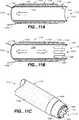
図11A乃至図11Cは、本発明のさらに他の実施形態を示しているが、この実施形態では活性電極1122はシャフト1127の一部分から形成されている。図11A乃至図11Cに示した実施形態は、機械的な篩の形態の活性電極を含んでいる。図11Aに示すように、活性電極1122を備えた遠位端端部1112は、外科的な患部における身体組織を処置するためのエネルギー適用表面1120を形成している。基端端部1114において、導体1116がシャフトに結合して、活性電極1122を電気的に活性化する。戻り電極1124は、シャフト1127の外側に配置されていて、絶縁体1128によって活性電極1122に対して電気的に絶縁されている。望ましくは、戻り電極1124はリング電極の形態であって、シャフト1127の円周のまわりに配置される。戻り導体1126は、戻り電極1124を電源に結合する。また、上述したように、戻りの電気経路を患者の身体に配置しても良い。シャフトの絶縁体1134はシャフト1127を被覆している。また、内部の吸引内腔1150は絶縁材料で裏打ちされている。
【0043】
図11Bに示した他の実施形態の活性電極は、図11Aの電気外科吸引器具と類似しているので、対応する要素には同一の参照符号を付している。この構成では、活性電極1122は切抜き部分1129を有していて、切抜き部分の縁部1180を備えた篩表面を形成している。活性電極に切抜き部分を備えた構成とすることで、活性電極1122は、縁部1180に電流が集中して、高い電流密度をエネルギー適用表面1120に形成する。従って、最大の切除と組合わせて、機械的な切断と篩の効果が達成される。さらに、流体の送出源に接続したときには内腔1150が流れ内腔として働いて、内腔を通して流体が送出され、また、吸引源に接続したときには同一の内腔1150が吸引内腔として働いて、内腔を通して吸引される。
【0044】
図11Cは、図11Bの電気外科器具の斜視図を示している。縁部1180はシャフトと絶縁体1128とを越えて突出していて、切除や切断又は凝固のための処置エネルギーを送出すると共に、不要な組織を機械的に削り落して除去する。縁部1180に電流が集中するので、組織に沿った正確な切断箇所に切除効果を提供することで、機械的な削り落しと切断とが容易になる。本実施形態では、処置された組織は、吸引内腔を通して外科的患部から吸引される。
【0045】
図12A及び図12Bは、本発明の他の実施形態を示しており、活性電極は十字形状に形成されていて、アームの延長部のまわりを通して吸引が提供される。図12A及び図12Bは、クロスファイヤーの単極の電極であって電極のまわりに吸引箇所を備えたものを示している。図12Aは、電気外科器具1210の活性電極1222を示した横断面図である。活性電極1222は、器具1210のシャフト1227の遠位端端部1212に配置されている。シャフト1227は、シャフト絶縁体1234で被覆されている。活性電極1222は、電気導体1216を介して電源(図示せず)に結合される。活性電極1222のアームの延長部は、ほとんど平坦である電極の本体を備えると共に、外向きに延在した縁部1280を形成している。活性電極1222のアームの間には、開口1225が形成されている。活性電極1222の中央部分を本体部分から盛上げて中央の縁部1280を形成しても良い。縁部1280を盛上げることによって、縁部に沿って電流が集中して、切除の効果のために、縁部1280に電気密度が増大する。また、縁部1280は、外科的患部における機械的な削り落しと篩との効果を同時に得るように構成し鋭利にしても良い。
【0046】
縁部1280の配置によれば、活性電極に電流が送出されることで、開口1225の閉塞が防止される。縁部1280に沿って電流が集中すると、外科的な患部から生じたあらゆる物質が開口1225を閉塞して、縁部1280の間におけるインピーダンスを増加させて、出力を増加させる。出力が増加すると、処置エネルギーが不要な物質を小さいサイズに切断して、開口を通り抜けられるようにする。例えば、開口1225のひとつの四分円を不要な物質が閉塞したとすると、閉塞された付近の縁部1280に沿ってインピーダンスが大きくなる。開口全体を通しての吸引力は等しいので、他の四分円では不均等に吸引力が増加して、それにより閉塞物を様々な軸線平面に沿って引張る。処置エネルギーの送出が増加することで、不要な物質がいずれかの開口を通って容易に動けるまでに、閉塞物の部分が切断される。この効果は、図1のメッシュの形態において、電極のデザインのために生じる切断効果が、吸引開口を通して、あらゆる閉塞物や不要な物質をさらに切断していたのと類似している。他の閉塞していない開口が生じさせる特異的な吸引が、特異的な軸線吸引効果を生じさせて、それにより閉塞物を取除く助けとなる。
【0047】
戻り電極1224は、吸引内腔1250の内部に配置されていて、上述したような、沸騰チャンバを形成する。電気エネルギーは、戻り導体1226によって、戻り電極1224から電源へと戻される。戻り電極1224は、絶縁体1228によって活性電極1222に対して電気的に絶縁される。
【0048】
図12Bは、図12Aの器具1212の斜視図である。本実施形態では、縁部1280が盛上がっていて、切除のためのカップないしポケットを形成している。縁部1280は、機械的な切断表面エッヂとして機能すると共に、効果的な切除のための電流集中エッヂとしても機能する。
【0049】
図13Aに示した他の実施形態による電気外科器具1310は、灰皿状の構成の活性電極1322を有している。活性電極322は、シャフト1327の遠位端端部1312に配置される。器具のシャフトは、シャフト絶縁体1334で被覆されている。活性電極1322は灰皿状の構成であって、エネルギー適用表面1320には切抜き部分1329が形成されている。切抜き部分1329を形成することによって、活性電極1322のエネルギー適用表面1320には縁部1380が形成される。縁部1380は、機械的な組織除去表面を形成すると同時に、最大のエネルギー送出効果を得るための電流集中縁部を形成する。また、開口1325の閉塞は、開口1325の近くに縁部1380を備えるように活性電極1322を構成することによって防止及び解消できる。電気導体1316は電極1322を電気的に電源(図示せず)へ結合する。活性電極1322は、吸引内腔1350に連通してなる中央開口1325を備えるように構成される。戻り電極1324は吸引内腔1350の中に配置されて、活性電極1322の基端方向に配置されており、上述のような沸騰チャンバを形成する。絶縁体1328は電極1322と電極1324とを絶縁する。また、内部ライニング1330が吸引内腔1350を裏打ちして、電気的及び熱的な絶縁体として機能する。
【0050】
図13Bは、図13Aの斜視図であって、活性電極322の灰皿状の構成が示されている。電極の切抜き部分1329は縁部1380を形成して、上述したような機械的及び電気的な効果を生じさせる。開口1325は、器具1310を通して吸引内腔1350に連通している。図13A及び図13Bは、中性の電極の内側の灰皿状の電極と電極を通しての吸引を示している。
【0051】
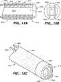
図14A及び図14Bは、図13A及び図13Bで説明した電気外科吸引器具1310の変形例の実施形態を示している横断面図と斜視図である。対応する要素には図13A及び図13Bと同じ符号を付している。本実施形態では、戻り電極1424はシャフト1427の外側に沿って配置されている。戻り電極1426は、活性電極1422から電源への電流の経路を完結させる。戻り電極1424は好ましくはシャフト1427の表面に配置されてなるリングの電極であって、絶縁体1428によって活性電極1422に対して絶縁されている。図14A及び図14Bは、中性の電極の外側の灰皿状の電極と、内腔を通しての吸引とを示している。
【0052】
図15A乃至図15Cは、上述した活性電極の変形例としての実施形態による灰皿状の電極をそれぞれ異なった視点から示した図である。対応する要素には同一の参照符号を付している。図15Aは、窪み型電極1522を示した拡大斜視図であって、活性電極1522を貫通する少なくともひとつの開口1525が備えられている。活性電極1522は、電流を集中させて円周縁部1580に沿って高い電流密度を作るように構成されている。縁部1580はエネルギー適用表面1520を形成する。切抜き部分1529は、電流の集中を最大にするようなパターンを縁部1580に沿って形成する。縁部1580に沿って電流が集中するために、機械的な削り落しと切除の効果とが同時に生じる。電流はまた、開口525の内部に形成されている縁部1580にも集中して、開口が閉塞されるのを防止する。活性電極にエネルギーが適用されると、表面1580の鋭利な縁部は、切除のためにRF電力を送出するための表面を提供すると共に、同時に、機械的な篩ないし削り落し表面を提供して、外科的な組織患部の組織を削り落す。電極1520の縁部1580を丸くして、滑らかな表面を形成するようにして、本発明の器具で彫刻を実行しても良いことを理解されたい。
【0053】
外科的な患部には切除及び/又は凝固の副産物が生じるが、内腔及び電気外科器具を通しての吸引によって生じた負圧が、追加的な物質を開口1525を通して吸引する。しかしながら、開口1525が閉塞し詰まることは、開口1525を通る流体と組織との流れを減少させるために、切除の効果を不必要に増加させる。切除及び切断の処置によって、生物学的な組織壊死片など外科処置の副産物が生じる。こうした物質は元の位置から取除かれて、外科的患部の中を自由に移動するので、生物学的組織はいずれかの又はすべての器具への開口を完全に閉塞させる。従って、物質と流体とが流れることによる冷却効果が減少して、患部への処置エネルギーの送出を増大させて、不必要な切除をしたり患者を傷害したりする可能性がある。
【0054】
閉塞及び潜在的な傷害に対応するために、縁部1580は図12に示すように構成されていて、縁部1580の部分が開口1525の付近又は内部に配置されるように構成される。開口525の内部に閉塞した組織によってインピーダンスが増加するために、組織は縁部1580でさらに処置されて、組織はさらに切断されて、開口1525を通り抜けられるサイズになる。開口1525の不規則な形状は、縁部1580と組合わされて、不均等かつ丸くない開口を提供し、電気的な効果と機械的な効果との双方が組合わされて、開口が閉塞するのを防止し、これにより電気外科器具1510の効率を増加させる。
【0055】
図15Bは、遠位端の電極の先端部1512を示した端面図である。エネルギー適用表面1520と縁部1580とに切抜き部分1529を備えている。表面1520の切抜き部分1529の数やサイズ及び配置を変更して異なった切除の効果とパターンを提供しても良いことを理解されたい。電流が集中して表面1520と縁部1580で最大の密度になるので、縁部1580に沿って切除、切断、及び/又は、凝固が生じる。
【0056】
図15Cは、図15Bの遠位端の先端部を示した横断面図であって、遠位端端部1512の活性電極1522を線A−Aに沿って示している。エネルギー適用表面1520は詳細に示しているように、電気的な切除の効果と機械的な削り落しの効果との双方のための鋭利な縁部1580を備えている。縁部1580は開口1525の部分に貫入していて、この開口は吸引内腔1550に通じている。上述した図12を参照すると、不均等な形態である開口1525を通る吸引の効果は、負圧が異なった軸線平面にわたって閉塞物を内腔の中へと引張ることで、吸引開口の閉塞や詰まりを防止する。例えば、不要な副産物の物質が開口1525に接触すると、それは縁部1580の部分に留まる。内腔と開口を通して吸引力が加えられているために、物質の一部は、縁部1580に沿って滞留している部分から離れている部分にかぶさる。これによって、物質は異なった軸線方向の平面においてねじれて回転して、そのために、不要な物質が移動して、開口1525を通り抜けられるように適合した物理的な配置になる。
【0057】
図16A及び図16Bは、本質的に双極であるような変形例の先端部の構成を示すと共に、本発明のさらに他の実施形態を示していて、この実施形態では、活性電極1622と戻り電極1624とが器具1610の遠位端端部1612のエネルギー適用表面1620の実質的に同一平面に配置されて、双極の構成を形成している。そのような電極1622と1624との配置を実現するために、各電極を弓形の要素として形成して、器具1610の遠位端端部612に配置する。電極1622と電極1624とは絶縁体1628によって支持されていて、この絶縁体は電極1622と電極1624とを電気的に絶縁するという追加的な機能も果す。絶縁体1628には切抜き部分629が形成されて、電極1622と1624との間隔を隔てると共に、もってさらに電気的に絶縁する。中央の開口1625によって吸引できる。
【0058】
電極1622と電極1624とは、それぞれ別々の導体要素1616と1626とによって、別々に電源に結合される。導体要素は好ましくは、器具1610の遠位端端部1612から基端端部1614へと内腔1650を通して延在する。導体要素1616と1626とは、絶縁体1628の中央の開口1625を通って、絶縁体1628の最も遠位端の端部にある電極1622と1624とに結合されるけれども、他の配置も本発明の範囲に含まれることを理解されたい。例えば、導体要素1616と1626とは、内腔1650と電極1622及び1624とを連通させるべく絶縁体1628を通るように形成されてなる通路を通って延在しても良い。内腔1650は上述したように吸引のために使用される。
【0059】
電気外科器具の遠位端の先端部にエネルギー適用表面領域を備えている上述したような構成は、吸引を出来ない器具にも適用可能であることを理解されたい。従って、器具1610の絶縁体1628は実質的に中実の要素であって、電極1622及び1624を電源に結合するための通路は有するものの、吸引の目的の通路は有していないようなものとしても良い。活性電極と戻り電極との配置をさらに変更して、図10及び図11に示すように、エネルギー適用表面が輪郭を有する(すなわち、完全に平坦ではない)ものの、依然として器具の遠位端端部に残されて、長手軸線に対して実質的に直交して、器具の側壁の遠位端部分から(図1及び図2の器具10のように)はみ出していないようにしても良い。
【0060】
図17A及び図17Bは、本発明の他の実施形態による電気外科吸引器具1710であって、この実施形態は、吸引能力を備えた2つの活性電極を有する本質的に双極の構成を有していて、活性電極1722と戻り電極1724とは同等のサイズになっていて、互いに近接して遠位端端部1712に配置されている。この構成の電極1722と1724とは本質的に双極の構成を形成する。活性電極1722は単一の円板形状の電極であって、絶縁体1728の内部における遠位端端部1712の中央に配置されている。戻り電極1724はリングの電極であって、実質的に絶縁体1728の円周の縁部における同一の平面に沿って配置されている。両方の電極の有効表面積は概略等しくて、送出される処置エネルギーは双方の電極で等しくなっている。絶縁体1728の内部には開口1725が配置されていて、吸引内腔1750と連通している。切除、切断、及び凝固は活性電極1722において生じて、吸引内腔に加えられる吸引によって、副産物や過剰な流体は開口1725に押し通される。
【0061】
図17Bは横断面図を示していて、活性電極1722は電気導体1716によって基端端部1714の電源(図示せず)に結合されている。戻り電極1724は延長部1736によって電気導体シャフト1727に電気的に結合されていて、電力供給の回路を完結させる。シャフト1727はシャフト絶縁体1734で被覆されている。
【0062】
図18A乃至図18Cは、本発明のさらに他の実施形態による電気外科吸引器具1810を示しており、この実施形態は、吸引内腔を備えた本質的に双極の構成であって、活性電極1822と戻り電極1824とは遠位端端部1812における同一表面に配置されている。活性電極と戻り電極とは実質的に同様に構成されていて、2つの導体1816と1826とシャフト1827を通して遠位端端部1812に電気的に結合されている。電極1822と電極1834とは絶縁体1828によって電気的に絶縁される。外科的患部にて等しい双極の効果が生じるように、両方の電極に等しいエネルギーが送出される。電極は両方とも、吸引開口1825の片側から開口を横切る箇所へと延在して、発電源へと戻る。電極のひとつは活性電極として働いて、もうひとつの電極が戻り電極として働く。発電源の極性は反転するので、いずれか一方の電極が活性電極又は戻り電極になることを理解されたい。両方の電極が吸引開口1825を横切るように構成したので、開口が詰まったり閉塞したりすることは防止ないし低減される。
【0063】
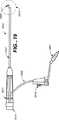
図19は、本発明による電気外科吸引器具1910を示した斜視図である。吸引ライン1952は基端のハンドル1917に取付けられる。吸引ライン1952は吸引装置及び結合具(図示せず)に結合されて、器具を通る負圧を提供し、これにより、切除された副産物はプローブのシャフト1927を通して遠位端の先端部1912から吸引される。電力結合具1914は器具1910を電源(図示せず)に結合する。アクチュエータ1918は吸引ライン1952を通る吸引の量と強さとを制御するもので、ローラで制御される。真空ラインコネクタ1957は吸引結合具に結合する。器具1910を通る外科的な物質を吸引するのに用いられる吸引の量と強さとを制御するためには、あらゆる装置ないし機構を使用できることを理解されたい。
【0064】
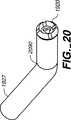
図20及び図21は、図19に示した本発明の遠位端端部1912についての変形例の実施形態であって、遠位端端部1912のシャフト1927が予め曲げられている。上述したように、吸引内腔が圧迫されたりつぶれたりして吸引を閉塞することのないように、シャフト1927はフレキシブルではないことが好ましい。吸引力を減少させることは、上述の如く、切除効果の増加につながる。図20では遠位端端部1912が30゜屈曲していて、図21では90゜屈曲している。予め曲げておく角度の大きさはこれらの特定の角度に制限されないけれども、電気外科の機能に予め機能を組合わせた製品は、組織や身体の他の部分の切除を必要とする外科的な手順に特に有用であることを理解されたい。切除の機能を実行するために、電気外科吸引器具に供給されるエネルギーは100〜500kHzの範囲である必要がある。この範囲は、器具を形成するのに用いられている材料に応じて、また、外科的手順における器具の特定の用途に応じて変化する。使用される最も低い周波数は代表的には、器具の使用が他の組織と干渉したり、その領域の神経を刺激したりすることのないように選択される。従って、選択した組織の領域を孤立して処置できる。使用される最も高い周波数は代表的には、その周波数によって達成される所望の結果に依存して制限される。例えば、高すぎる周波数では、適切な切除が行なわれずに、壊死片による内腔の閉塞が生じるだろう。
【0065】
電力は、商業的に利用可能なRFエネルギー源によって提供される。そのようなRFエネルギー源は電気外科器具の温度を制御する発電源を含む。電力はフィードバックで調節して、過大出力や不要な切除若しくは凝固などが生じないようにする。
【0066】
以上のように、本発明による電気外科器具はあらゆる種類の用途と手順に使用できるが、それは電源から供給されるエネルギーの性質によって異なる。従って、本発明の電気外科器具に供給するエネルギーは所望の用途に応じて変更されることを理解されたい。エネルギーレベルも使用中には変化させて、例えば切除を行なった後で必要に応じて焼灼や凝固をさせるなど、様々な機能を実行する。
【0067】
本発明は、外科の器具と、患者の処置領域にエネルギーを適用するための方法、ならびに、外科的な患部から煙や、空気気泡、及び生物学的な壊死片などの不要な物質を吸引するための方法を含む。
【0068】
本発明は、電気外科と吸引とを組合わせた器具を含み、かかる器具は、処置領域にわたって均一にエネルギーを加えると共に、詰まりを制限するために吸引ができるような、エネルギー適用表面領域を提供する。
【0069】
本発明は、電気外科と吸引とを組合わせた器具を含み、かかる器具は、器具の遠位端の先端部に活性電極と戻り電極との両方を有していて、エネルギーの分配は遠位端の先端部の表面に実質的に限定される。
【0070】
本発明のひとつの実施形態では、外科の器具は、遠位端と基端部との端部を有するシャフトであって遠位端端部に少なくともひとつの吸引開口を有するような少なくともひとつの吸引内腔を形成している上記シャフトと、シャフトの遠位端端部に配置されて電源に電気的に結合されている活性電極であってエネルギー適用表面を形成する上記活性電極と、電源に電気的に結合されている戻り電極と、を含む。
【0071】
本発明のひとつの実施形態では、外科の器具は、基端端部と遠位端端部と長手軸線とを有するようなシャフトと、遠位端端部に配置されて遠位端端部に結合されて、遠位端端部に概略長手軸線に対して直交するようなエネルギー適用表面を形成する活性電極及び戻り電極と、電極を電源に結合してそれぞれの電極間に電圧を加えるためにシャフトの基端端部付近に配置されているコネクタと、を含む。
【0072】
本発明のひとつの実施形態では、エネルギー適用表面に沿った処置患部へエネルギーを伝達及び適用するための少なくともひとつの電極を備えたカニューレを有すると共に、処置領域から不要な物質と外科的な副産物とを吸引するための吸引内腔を有するような、プローブが提供される。好ましくは、少なくともひとつの電極、つまり活性電極がプローブの遠位端端部に備えられる。戻り電極ないし中性電極は、患者の身体の上か、または、プローブに配置される。器具が結合されるエネルギー発生器は好ましくは、器具に加える電力、周波数、及び電圧を調節するために使用される制御装置を含んでいて、器具を使用した処置のタイプを変更する。調節にはフィードバック制御を含むと良い。
【0073】
本発明のひとつの実施形態では、活性電極に複数の小さな貫通通路が備えられて、器具の吸引内腔と流体的に連通する。そのような吸引通路を備えた活性電極は、メッシュや、打抜き孔を有する円板や、絶縁体で支持された複数の導体であって貫通する開口を備えた導体などである。従って、処置領域の吸引は、エネルギー適用表面の少なくとも一部分を通ってなされる。必要に応じて、活性電極と戻り電極との双方を実質的に同一平面に配置しても良く、これによりエネルギーの分配は、遠位端の先端部の表面領域などの実質的に平坦な表面領域に制約される。
【0074】
本発明の他の実施形態では、外科の器具は、遠位端と基端との端部を有するようなシャフトを有する。シャフトはまた、少なくともひとつの内腔を形成する。内腔は遠位端端部に少なくともひとつの吸引開口を有する。活性電極は、シャフトの遠位端端部に配置されて、エネルギー適用表面を形成する。活性電極は電源に電気的に結合される。電源には戻り電極が結合され、活性電極から戻り電極への電流の経路が吸引開口を通り抜けるようになっていて、開口が詰まるのを防止する。戻り電極は患者の身体の部分に、または、シャフトに配置される。
【0075】
内腔に負圧が加えられると、外科的な患部にある物質が吸引開口を通して吸引される。開口は、遠位端端部において吸引した物質が詰まるのを防ぐように構成される。吸引開口は、吸引開口の詰まりを防止するように構成されてなる活性電極によって形成されて、吸引された不要な物質を連続的に乾燥させて、物質が容易に吸引内腔を通り抜けるようにする。
【0076】
本発明のこれらの及び他の特徴ならびに利点については、添付図面と上述の発明の詳細な説明とから容易に明らかになるが、発明の範囲は特許請求の範囲によって定められる。
【0077】
本発明による外科的な患部の組織を電気外科的に処置する方法は、処置すべき組織に近接させてあるいは接触させてエネルギー適用表面を配置する段階と、エネルギー適用表面にわたるように処置領域にエネルギーを加える段階と、エネルギーを適用したために生じた物質をエネルギー適用表面を通して吸引する段階と、エネルギー適用表面を通り抜ける吸引された物質にエネルギーを加える段階と、を含む。
【0078】
任意的には、電気外科的に組織を処置する方法を実施するために使用するエネルギーは、高周波エネルギーである。任意的には、電気外科的に組織を処置する方法を実施するために利用するエネルギー適用表面は、外科器具の遠位端端部に形成すか及び/又は活性電極によって形成する。任意的には、電気外科的な組織の処置における吸引の段階は、エネルギー適用表面にある閉塞物に特異的な吸引力を生じさせるような不均等な平面で行なわれて、エネルギー適用表面を通して閉塞物を容易に吸引できるようにする。
【0079】
上述の説明と図面とは本発明の好ましい実施形態を表しているけれども、これに様々な付加、改変、及び置換を行なっても、特許請求の範囲に定められている発明の精神と範囲とから逸脱することはないことを理解されたい。特に、当業者には自明であるように、本発明を他の特定の形態や、構造、配置、大きさ、及び他の要素材料、及び構成要素で実施したとしても、発明の精神や本質的な特性から逸脱することはない。本願において開示した実施形態は、従って、あらゆる点において例示的であって制限的なものではなく、発明の範囲は、特許請求の範囲に記載されており、上述の詳細な説明に限定されるものではない。
【図面の簡単な説明】
【図1】 図1は、本発明の原理によって形成されてなる電気外科吸引器具を示す斜視図である。
【図2】 図2は、図1のA−A線に沿った横断面図である。
【図3】 図3は、図1の器具の遠位端先端部を示した端面図である。
【図4】 図4は、図1の器具の遠位端先端部を示した端面図であるが、他の先端部の実施形態を示している。
【図5】 図5は、本発明による電気外科吸引器具を示した斜視図であって、凸面状に構成されてなる活性電極の遠位端先端部を備えている。
【図6】 図6は、本発明による電気外科吸引器具を示した斜視図であって、凹面状に構成されてなる活性電極の遠位端先端部を備えている。
【図7】 図7は、図5及び図6の器具の遠位端先端部の部分について、その基本的部分を示した横断面図である。
【図8】 図8A及び図8Bは、電気外科吸引器具を示しているそれぞれ横断面図と端面図とであって、この実施形態はコイル状の形態の活性電極と内部戻り電極とを備えている。
【図9】 図9A及び図9Bは、本発明による電気外科吸引器具を示しているそれぞれ横断面図と端面図であって、リングの形態の活性電極と内部戻り電極とを示している。
【図10】 図10A及び図10Bは、本発明による電気外科吸引器具を示しているそれぞれ横断面図と端面図であって、この実施形態ではプロング状の形態の活性電極と内部戻り電極とを示している。
【図11】 図11A乃至図11Cは、本発明による電気外科吸引器具をそれぞれ示した横断面図と斜視図であって、機械的に篩状である形態の活性電極と外部戻り電極とを示している。ここで、図11Aはリング状の篩の形態を示しており、図11Bはラスプ状の篩の形態を示している。
【図12】 図12A及び図12Bは、他の実施形態による電気外科吸引器具をそれぞれ示した横断面図と斜視図であって、機械的な篩であると共にエネルギーを送り届ける、十字の形態を有してなる活性電極を示している。
【図13】 図13A及び図13Bは、図12A及び図12Bの吸引器具に変更を加えたものの横断面図と斜視図であって、機械的な篩であって、内部戻り電極と共にエネルギーを送り届ける、灰皿の形状の活性電極を示している。
【図14】 図14A及び図14Bは、図13A及び図13Bの器具をそれぞれ示した横断面図と斜視図であって、外部戻り電極を示している。
【図15】 図15A乃至図15Cは、本発明のひとつの実施形態による電気外科吸引器具の先端部を詳しく示した斜視図と端面図と横断面図とであって、図15Aは、吸引開口を備えた活性電極を示した詳細な斜視図であり、図15Bは、活性電極を示した端面図であって、図15Cは、図1513のA−A線に沿った横断面図である。
【図16】 図16A及び図16Bは、本発明の他の実施形態による器具を示した横断面図と斜視図であって、遠位端先端部が本質的に双極構成になっていて単一の吸引開口を有している。
【図17】 図17A及び図17Bは、本発明の他の実施形態による器具を示した斜視図と横断面図であって、複数の吸引開口を有してなる本質的に双極構成の遠位端先端部を示している。
【図18】 図18A乃至図18Cは、他の実施形態における遠位端先端部を示した横断面図と端面図と斜視図とであって、この先端部の単一の吸引開口には、ループ状のプロングの形態に形成されてなる活性電極と戻り電極との双方が備えられ、エネルギーを適用する表面を形成している。
【図19】 図19は、本発明による電気外科器具の全体を示した斜視図であって、このプローブは、ハンドルと、遠位端先端部を備えていて吸引ラインと共に処置を行なうためのシャフトとを有し、制御装置もまた示されている。
【図20】 図20は、本発明による図19の遠位端端部シャフトの他の実施形態を示しており、遠位端端部を30゜屈曲させておいたものを示している。
【図21】 図21は、本発明による図19の遠位端端部シャフトの他の実施形態を示しており、遠位端端部を90゜屈曲させておいたものを示している。[0001]
BACKGROUND OF THE INVENTION
The present invention relates to an electrosurgical instrument and apparatus for treating a surgical lesion, such as a biological tissue of a human or animal body, by applying energy. In particular, the present invention relates to surgical devices and methods that combine high frequency energy to alter tissue properties, such as ablation and aspiration of any by-product from a surgical lesion.
[0002]
[Prior art]
Numerous surgical instruments are known to those skilled in the art for treating biological tissue by applying energy in various medical procedures. For example, Lindstrom et al. US Pat. No. 4,593,691, Hetzel US Pat. No. 4,033,351 and Abele et al. US Pat. No. 5,403,311 cut or excise tissue. 1 is an illustration of an electrosurgical probe for use during electrosurgical procedures such as. US Pat. No. 5,458,596 to Lax et al. Shows an example of an electrosurgical probe for contracting tissue by delivering electrical energy to the tissue to be treated. Also, Morrison U.S. Pat. No. 3,828,780 and Hagen U.S. Pat. No. 5,277,696 show an electrosurgical instrument that delivers electrical energy for coagulation during a surgical procedure. .
[0003]
The use of these instruments typically requires the transfer of energy to an electrosurgical probe or distal end of the instrument. The distal end is inserted into the body to apply energy to the patient's surgical lesion during the procedure. The frequency, power, and voltage that are generated from the electrical instrument and transmitted to the distal end are selected depending on the type of procedure for which the instrument is to be used. For example, such instruments are used in a variety of procedures such as heating, softening, shrinking, cutting, and excising tissue.
[0004]
Since such instruments are used for different procedures, the tissue (or other body part) being treated will respond differently depending on the procedure being performed. For example, if an instrument is used to remove tissue, smoke or charcoal is generated during the procedure, or residual necrotic tissue fragments remain after the procedure.
[0005]
Also, there may be unwanted air bubbles and excess fluid in the affected area of the procedure, which interferes with the effective treatment of the tissue and must be removed from the surgical affected area during the procedure. I must. Accordingly, there is a need to provide an electrosurgical device that suctions the area to be treated to remove smoke, tissue necrosis, excess fluid, and other undesirable materials from the affected tissue area being treated.
[0006]
However, during the use of prior art instruments such as the numerous instruments described above, it was generally necessary to provide a separate suction device to remove unwanted material. Using two separate instruments means that the suction instrument is inserted into the surgical site separately and used to remove it from the site before and after insertion or use of the electrosurgical instrument. The treatment time is increased because it must be done. In addition, separate suction devices may be inserted into other access point surgical sites, but this creates other scars on the patient's body, which can cause complications such as infections and scarring. There is sex.
[0007]
The suction devices disclosed by Wojciechowicz US Pat. No. 5,520,685, Bales US Pat. No. 4,682,596 and Beale US Pat. No. 4,347,842 are variously combined. And configured with an electrosurgical probe. In addition, the electrosurgical device disclosed by Smith, US Pat. No. 5,195,959, electrically aspirates and perfuses the conductor fluid, bringing more material into the surgical site. As such, they need to be removed during the procedure. In particular, Wojciechowicz discloses an aspiration coagulator with an aspiration lumen to aspirate electrosurgical by-products from the tip of the instrument through the interior. In addition, Hagen discloses a suction device for sucking fluid through a surgical probe.
[0008]
[Problems to be solved by the invention]
However, placing the suction lumen relative to the electrosurgical part can cause the suction lumen to become blocked or clogged, which complicates the surgical procedure and is unnecessary or unnecessary. Cause a severe resection. Carbonized and resected tissue and coagulated blood often clog the tip of the electrosurgical device.
[0009]
[Means for Solving the Problems]
Accordingly, it is desirable to provide an instrument that not only treats a patient, but also allows aspiration of the treatment area to also be performed during the procedure and used to remove unwanted material simultaneously. It is done. Surgical devices and methods should be simple and operate in a standard surgical room environment. With electrosurgical instruments, the surgeon should be able to ablate, cut, or coagulate using the same device and provide a suction means to aspirate the surgical byproduct from the surgical lesion. Suction and suction should be clogged and the device should not be subject to unwanted or adverse effects due to blockage. Such instruments and methods need to be able to precisely treat biological tissue with energy and allow surgeons to quickly perform medical procedures without having to utilize multiple treatment instruments. It needs to be tempered.
[0010]
Hereinafter, the invention will be described in detail with reference to the accompanying drawings. In the drawings, corresponding elements are given corresponding reference numerals.
[0011]
DETAILED DESCRIPTION OF THE INVENTION
1 and 2 illustrate an embodiment of an
[0012]
The
[0013]
As shown in FIGS. 1 and 2, the
[0014]
As shown in FIG. 2, power is transmitted from the
[15]
[0016]
In addition, the
[0017]
The
[0018]
The
[0019]
In order to facilitate aspiration during electrosurgical procedures such as ablation and coagulation, the
[0020]
The gap between the mesh allows fluid to pass through it, so unwanted material (such as excised tissue, smoke, air bubbles, and other elements, or biological debris) can pass through the mesh. Then, it enters the
[0021]
Furthermore, in the present embodiment, the
[0022]
Referring to FIG. 3, an end view of the electrosurgical probe of FIGS. 1 and 2 is shown. The
[0023]
In FIG. 4, the
[0024]
Hereinafter, as shown in FIGS. 5 to 7, an electrode having a configuration of a modified example, which forms an energy application surface and allows suction through the surface, will be described. FIGS. 5 to 7 show the basic concept of the configuration of the tip of a variation of the evaporation electrode, which is monopolar and has a suction capability. It will be appreciated that the configuration of the active electrode can be varied as needed as long as the internal lumen through the shaft of the electrosurgical suction instrument of the present invention is accessible externally. Furthermore, it will be understood that the active electrode configuration and the relative arrangement of the active electrode with respect to the return electrode can also be varied. However, it is desirable that the resulting energy application surface span at least a portion of the lumen opening so that the energy application surface and the suction process can cooperate. This is to reduce occlusion.
[0025]
In FIG. 5, the
[0026]
As shown in FIG. 5, the
[0027]
As a variation, a ring-shaped
[0028]
FIG. 7 illustrates the placement and electrical coupling of
[0029]
[0030]
The size of the active electrode shown in FIGS. 5 to 7 is appropriate for the return electrode, and conversely, the return electrode can be said to be appropriate for the active electrode. It should be understood that using an instrument is similar to the effect produced by a bipolar electrosurgical instrument. In a typical bipolar instrument, both electrodes are the same size and are placed in close proximity so that both electrodes equally affect the area of tissue to which the instrument is applied. By making the active electrode and the return electrode approximately equal in size, a bipolar effect can be achieved also in the present invention. Furthermore, it should be understood that in any embodiment of the present invention, the electrodes can be sized to achieve a bipolar effect. In addition, the return electrode of the present invention may be disposed on the patient's body as described above.
[0031]
FIGS. 8A and 8B, FIGS. 9A and 9B, and FIGS. 10A and 10B show a similar embodiment of the electrosurgical suction instrument of the present invention comprising a monopolar tip configuration. . For the sake of brevity, the description of substantially the same elements or features (they are given the same reference numerals) of the embodiment of FIGS. 8 to 10 will not be repeated in detail. Reference is made to the description of the corresponding elements in FIGS.
[0032]
8A and 8B illustrate an
[0033]
In this configuration, the
[0034]
Further, the
[0035]
9A and 9B show an
[0036]
FIG. 9A is a cross-sectional view showing the ring
[0037]
[0038]
9B is an end view showing the end of the distal end of the device of FIG. 9A. The
[0039]
FIGS. 10A and 10B show an
[0040]
FIG. 10A is a cross-sectional view showing the prong
[0041]
FIG. 10B is an end view showing the end of the distal end of the device of FIG. 10A. The
[0042]
11A-11C illustrate yet another embodiment of the present invention, in which the
[0043]
Since the active electrode of the other embodiment shown in FIG. 11B is similar to the electrosurgical suction instrument of FIG. 11A, corresponding elements have the same reference numerals. In this configuration, the
[0044]
FIG. 11C shows a perspective view of the electrosurgical instrument of FIG. 11B.
[0045]
12A and 12B illustrate another embodiment of the present invention where the active electrode is formed in a cross shape and suction is provided around the extension of the arm. FIG. 12A and FIG. 12B show a cross-fire monopolar electrode having a suction location around the electrode. FIG. 12A is a cross-sectional view showing the
[0046]
According to the arrangement of the
[0047]
The
[0048]
FIG. 12B is a perspective view of the
[0049]
An
[0050]
FIG. 13B is a perspective view of FIG. 13A and shows an ashtray-like configuration of the active electrode 322. The cut-
[0051]
14A and 14B are a cross-sectional view and a perspective view showing a modified embodiment of the
[0052]
15A to 15C are views showing ashtray-like electrodes according to the embodiment as a modification of the active electrode described above from different viewpoints. Corresponding elements are given the same reference numerals. FIG. 15A is an enlarged perspective view showing the
[0053]
Surgical lesions produce ablation and / or coagulation by-products, but the negative pressure created by aspiration through the lumen and electrosurgical instrument draws additional material through
[0054]
To accommodate occlusions and potential injuries, the
[0055]
FIG. 15B is an end view showing the distal end electrode tip 1512. The
[0056]
FIG. 15C is a cross-sectional view of the distal end tip of FIG. 15B, showing the
[0057]
FIGS. 16A and 16B show a variation of the tip configuration that is essentially bipolar, as well as yet another embodiment of the present invention, in which an
[0058]
[0059]
It should be understood that a configuration such as that described above with an energy application surface area at the distal tip of the electrosurgical instrument is also applicable to instruments that cannot be aspirated. Thus, the
[0060]
17A and 17B are an
[0061]
FIG. 17B shows a cross-sectional view where the
[0062]
FIGS. 18A-18C illustrate an
[0063]
FIG. 19 is a perspective view illustrating an
[0064]
20 and 21 show a modified embodiment of the distal end 1919 of the present invention shown in FIG. 19, in which the
[0065]
Power is provided by commercially available RF energy sources. Such RF energy sources include a power generation source that controls the temperature of the electrosurgical instrument. The power is adjusted with feedback to avoid excessive output, unnecessary ablation or coagulation.
[0066]
As described above, the electrosurgical instrument according to the present invention can be used for all kinds of applications and procedures, depending on the nature of the energy supplied from the power source. Accordingly, it should be understood that the energy delivered to the electrosurgical instrument of the present invention will vary depending on the desired application. The energy level is also changed during use to perform various functions, such as cauterization or coagulation as necessary after ablation.
[0067]
The present invention is a surgical instrument, a method for applying energy to a treatment area of a patient, and unwanted material such as smoke, air bubbles and biological debris from a surgical lesion. Including methods for:
[0068]
The present invention includes a combined electrosurgical and aspirating instrument that provides an energy application surface area that applies energy uniformly across the treatment area and allows aspiration to limit clogging. .
[0069]
The present invention includes an instrument that combines electrosurgery and aspiration, such an instrument having both an active electrode and a return electrode at the distal end of the instrument, the energy distribution being distal. It is substantially limited to the surface of the tip part of the end.
[0070]
In one embodiment of the present invention, the surgical instrument is a shaft having a distal end and a proximal end, at least one suction opening having at least one suction opening at the distal end end. The shaft forming a lumen; the active electrode disposed at the distal end of the shaft and electrically coupled to a power source to form an energy application surface; And a return electrode that is mechanically coupled.
[0071]
In one embodiment of the present invention, a surgical instrument includes a shaft having a proximal end, a distal end, and a longitudinal axis, and a distal end that is disposed at the distal end. An active electrode and a return electrode, coupled to form an energy application surface at the distal end generally orthogonal to the longitudinal axis, and for coupling the electrode to a power source and applying a voltage between the respective electrodes And a connector disposed near a proximal end portion of the shaft.
[0072]
In one embodiment of the present invention, a cannula having at least one electrode for transferring and applying energy to a treatment area along an energy application surface and having unwanted substances and surgical byproducts from the treatment area A probe is provided having an aspiration lumen for aspirating. Preferably, at least one electrode, the active electrode, is provided at the distal end of the probe. The return or neutral electrode is placed on the patient's body or on the probe. The energy generator to which the instrument is coupled preferably includes a controller that is used to regulate the power, frequency, and voltage applied to the instrument to change the type of treatment using the instrument. Adjustment may include feedback control.
[0073]
In one embodiment of the invention, the active electrode is provided with a plurality of small through passages in fluid communication with the suction lumen of the instrument. The active electrode having such a suction passage is a mesh, a disk having a punched hole, a conductor having a plurality of conductors supported by an insulator and having an opening therethrough. Accordingly, suction of the treatment area is made through at least a portion of the energy application surface. If desired, both the active and return electrodes may be substantially coplanar so that the energy distribution is substantially flat, such as the surface area of the distal tip. Limited by region.
[0074]
In another embodiment of the present invention, the surgical instrument has a shaft having a distal end and a proximal end. The shaft also forms at least one lumen. The lumen has at least one suction opening at the distal end. An active electrode is disposed at the distal end of the shaft to form an energy application surface. The active electrode is electrically coupled to the power source. A return electrode is coupled to the power source so that a current path from the active electrode to the return electrode passes through the suction opening to prevent the opening from becoming clogged. The return electrode is placed on a part of the patient's body or on the shaft.
[0075]
When negative pressure is applied to the lumen, the material in the surgical lesion is aspirated through the aspiration opening. The opening is configured to prevent clogged aspirated material at the distal end. The suction opening is formed by an active electrode configured to prevent clogging of the suction opening to continuously dry the sucked unwanted material so that the material can easily pass through the suction lumen. .
[0076]
These and other features and advantages of the present invention will be readily apparent from the accompanying drawings and detailed description of the invention set forth above, the scope of which is defined by the appended claims.
[0077]
The method of electrosurgically treating a surgically affected tissue according to the present invention comprises the steps of placing an energy application surface in proximity to or in contact with the tissue to be treated, and energy in the treatment area over the energy application surface. Applying the energy, sucking the material resulting from the application of energy through the energy application surface, and applying energy to the aspirated material passing through the energy application surface.
[0078]
Optionally, the energy used to perform the electrosurgical tissue treatment method is radio frequency energy. Optionally, the energy application surface utilized to perform the electrosurgical tissue treatment method is formed at the distal end of the surgical instrument and / or by an active electrode. Optionally, the aspiration step in the electrosurgical tissue treatment is performed in an uneven plane that creates a specific aspiration force on the occlusion on the energy application surface and occludes through the energy application surface. Make things easy to aspirate.
[0079]
Although the above description and drawings represent preferred embodiments of the present invention, various additions, modifications, and substitutions may be made without departing from the spirit and scope of the invention as defined in the claims. It should be understood that there is no departure. In particular, as will be apparent to those skilled in the art, the spirit and nature of the invention, even if the invention is embodied in other specific forms, configurations, arrangements, sizes, and other element materials and components. There are no departures from these characteristics. The embodiments disclosed herein are therefore illustrative and not restrictive in every respect, and the scope of the invention is set forth in the following claims and is limited to the above detailed description. is not.
[Brief description of the drawings]
FIG. 1 is a perspective view of an electrosurgical suction instrument formed in accordance with the principles of the present invention.
FIG. 2 is a cross-sectional view taken along line AA in FIG.
FIG. 3 is an end view showing the distal end tip of the instrument of FIG. 1;
FIG. 4 is an end view of the distal tip of the instrument of FIG. 1, but showing another tip embodiment.
FIG. 5 is a perspective view showing an electrosurgical suction device according to the present invention, and includes a distal end tip portion of an active electrode configured in a convex shape.
FIG. 6 is a perspective view showing an electrosurgical suction device according to the present invention, and includes a distal end tip portion of an active electrode configured in a concave shape.
FIG. 7 is a cross-sectional view showing the basic portion of the distal end tip portion of the instrument of FIGS. 5 and 6;
8A and 8B are a cross-sectional view and an end view, respectively, showing an electrosurgical suction instrument, the embodiment comprising an active electrode and an internal return electrode in coiled form. Yes.
9A and 9B are a cross-sectional view and an end view, respectively, illustrating an electrosurgical suction instrument according to the present invention, showing an active electrode and an internal return electrode in the form of a ring.
FIGS. 10A and 10B are a cross-sectional view and an end view, respectively, showing an electrosurgical suction instrument according to the present invention, which in this embodiment includes a prong-shaped active electrode and an internal return electrode. Show.
11A to 11C are a cross-sectional view and a perspective view, respectively, showing an electrosurgical suction instrument according to the present invention, showing an active electrode and an external return electrode in the form of a mechanical sieve. ing. Here, FIG. 11A shows the form of a ring-shaped sieve, and FIG. 11B shows the form of a rasped sieve.
FIGS. 12A and 12B are a cross-sectional view and a perspective view, respectively, of an electrosurgical suction device according to another embodiment, having a cross-shaped configuration that is a mechanical sieve and delivers energy. An active electrode is shown.
13A and 13B are cross-sectional and perspective views of a modification of the suction device of FIGS. 12A and 12B, a mechanical sieve that delivers energy with an internal return electrode. Figure 2 shows an active electrode in the form of an ashtray.
FIGS. 14A and 14B are cross-sectional and perspective views, respectively, showing the instrument of FIGS. 13A and 13B, showing an external return electrode.
15A to 15C are a perspective view, an end view, and a cross-sectional view showing in detail a distal end portion of an electrosurgical suction instrument according to one embodiment of the present invention, and FIG. 15A shows a suction opening. FIG. 15B is an end view showing the active electrode, and FIG. 15C is a cross-sectional view taken along the line AA of FIG. 1513.
FIGS. 16A and 16B are cross-sectional and perspective views of an instrument according to another embodiment of the present invention, with a distal end tip essentially in a bipolar configuration and a single unit. Has a suction opening.
FIGS. 17A and 17B are a perspective view and a cross-sectional view of an instrument according to another embodiment of the present invention, with a distal end in an essentially bipolar configuration having a plurality of suction apertures. The end tip is shown.
18A-18C are a cross-sectional view, an end view, and a perspective view of a distal end tip in another embodiment, wherein a single suction opening in the tip includes Both active and return electrodes formed in the form of looped prongs are provided to form a surface to which energy is applied.
FIG. 19 is an overall perspective view of an electrosurgical instrument according to the present invention, in which the probe includes a handle and a distal end tip for performing a procedure with a suction line. A controller is also shown.
20 shows another embodiment of the distal end end shaft of FIG. 19 according to the present invention, with the distal end end bent at 30 °. FIG.
FIG. 21 shows another embodiment of the distal end end shaft of FIG. 19 according to the present invention, with the distal end end bent 90 °.
Claims (5)
Translated fromJapanese前記電極手段は、遠位端端部に開口に近接して取り付けられている活性電極と、遠位端端部に開口に近接して取り付けられている戻り電極と、を含み、活性電極に高周波エネルギーを供給したときに、高周波エネルギーが活性電極から開口の少なくとも一部分をわたるようにして戻り電極へ通り、
前記活性電極は、吸引された物質の前記内腔内での詰まりを防止するために、前記内腔の前記断面積より小さい断面積を備えた活性電極用の開口を有し、
前記活性電極は、灰皿状の構成であり、前記活性電極用の開口を取り囲むエネルギー適用表面を有し、このエネルギー適用表面の周辺部は、機械的な縁部及び電流集中縁部として機能するような縁部を構成する複数の切抜き部分を有する、ことを特徴とする外科器具。An elongate probe member having a proximal end and a distal end edge, andan elongated member, such as having a suction lumenthat not extend from the proximal end to the opening at the distal end edge, an electrode means mountedby the distal end edge of the elongate probe member, and a said electrode meansextending over at least a portion of theopening,
The electrode means includes an active electrode attached to the distal end end proximate to the opening and a return electrode attached to the distal end end proximate to the opening, the high frequency being applied to the active electrode When supplying energy, high frequency energy passes from the active electrode across the opening to the return electrode,
The active electrode has an opening for the active electrode with a cross-sectional area smaller than the cross-sectional area of the lumen to prevent clogging of the aspirated material within the lumen;
The active electrode has an ashtray-like configuration and has an energy application surface surrounding an opening for the active electrode so that the periphery of the energy application surface functions as a mechanical edge and a current concentration edge. A surgical instrumentcomprising a plurality of cut-out portions constituting a flexible edge .
Applications Claiming Priority (3)
| Application Number | Priority Date | Filing Date | Title |
|---|---|---|---|
| US09/412,878US6379350B1 (en) | 1999-10-05 | 1999-10-05 | Surgical instrument for ablation and aspiration |
| US09/412,878 | 1999-10-05 | ||
| PCT/US2000/027611WO2001024720A1 (en) | 1999-10-05 | 2000-10-05 | Surgical instrument for ablation and aspiration |
Publications (3)
| Publication Number | Publication Date |
|---|---|
| JP2003525662A JP2003525662A (en) | 2003-09-02 |
| JP2003525662A5 JP2003525662A5 (en) | 2007-09-20 |
| JP4263863B2true JP4263863B2 (en) | 2009-05-13 |
Family
ID=23634856
Family Applications (1)
| Application Number | Title | Priority Date | Filing Date |
|---|---|---|---|
| JP2001527721AExpired - Fee RelatedJP4263863B2 (en) | 1999-10-05 | 2000-10-05 | Surgical instruments for excision and aspiration |
Country Status (9)
| Country | Link |
|---|---|
| US (3) | US6379350B1 (en) |
| EP (1) | EP1223877B1 (en) |
| JP (1) | JP4263863B2 (en) |
| KR (1) | KR20020047213A (en) |
| AT (1) | ATE366086T1 (en) |
| AU (1) | AU1074201A (en) |
| CA (1) | CA2386763A1 (en) |
| DE (1) | DE60035425T2 (en) |
| WO (1) | WO2001024720A1 (en) |
Families Citing this family (427)
| Publication number | Priority date | Publication date | Assignee | Title |
|---|---|---|---|---|
| US6770071B2 (en)* | 1995-06-07 | 2004-08-03 | Arthrocare Corporation | Bladed electrosurgical probe |
| US7297145B2 (en) | 1997-10-23 | 2007-11-20 | Arthrocare Corporation | Bipolar electrosurgical clamp for removing and modifying tissue |
| US6974453B2 (en) | 1993-05-10 | 2005-12-13 | Arthrocare Corporation | Dual mode electrosurgical clamping probe and related methods |
| US6053172A (en)* | 1995-06-07 | 2000-04-25 | Arthrocare Corporation | Systems and methods for electrosurgical sinus surgery |
| US5697882A (en) | 1992-01-07 | 1997-12-16 | Arthrocare Corporation | System and method for electrosurgical cutting and ablation |
| US6063079A (en)* | 1995-06-07 | 2000-05-16 | Arthrocare Corporation | Methods for electrosurgical treatment of turbinates |
| US6896674B1 (en) | 1993-05-10 | 2005-05-24 | Arthrocare Corporation | Electrosurgical apparatus having digestion electrode and methods related thereto |
| US6832996B2 (en) | 1995-06-07 | 2004-12-21 | Arthrocare Corporation | Electrosurgical systems and methods for treating tissue |
| US6749604B1 (en) | 1993-05-10 | 2004-06-15 | Arthrocare Corporation | Electrosurgical instrument with axially-spaced electrodes |
| US6602248B1 (en)* | 1995-06-07 | 2003-08-05 | Arthro Care Corp. | Methods for repairing damaged intervertebral discs |
| US7393351B2 (en) | 1995-06-07 | 2008-07-01 | Arthrocare Corporation | Apparatus and methods for treating cervical inter-vertebral discs |
| WO2003024506A2 (en) | 2001-09-14 | 2003-03-27 | Arthrocare Corporation | Methods and apparatus for treating intervertebral discs |
| US6837888B2 (en)* | 1995-06-07 | 2005-01-04 | Arthrocare Corporation | Electrosurgical probe with movable return electrode and methods related thereto |
| US6837887B2 (en) | 1995-06-07 | 2005-01-04 | Arthrocare Corporation | Articulated electrosurgical probe and methods |
| US20050004634A1 (en) | 1995-06-07 | 2005-01-06 | Arthrocare Corporation | Methods for electrosurgical treatment of spinal tissue |
| US6805130B2 (en)* | 1995-11-22 | 2004-10-19 | Arthrocare Corporation | Methods for electrosurgical tendon vascularization |
| US6726684B1 (en)* | 1996-07-16 | 2004-04-27 | Arthrocare Corporation | Methods for electrosurgical spine surgery |
| US7357798B2 (en)* | 1996-07-16 | 2008-04-15 | Arthrocare Corporation | Systems and methods for electrosurgical prevention of disc herniations |
| US6620155B2 (en) | 1996-07-16 | 2003-09-16 | Arthrocare Corp. | System and methods for electrosurgical tissue contraction within the spine |
| US6645203B2 (en)* | 1997-02-12 | 2003-11-11 | Oratec Interventions, Inc. | Surgical instrument with off-axis electrode |
| US6126682A (en) | 1996-08-13 | 2000-10-03 | Oratec Interventions, Inc. | Method for treating annular fissures in intervertebral discs |
| US6699244B2 (en)* | 1997-02-12 | 2004-03-02 | Oratec Interventions, Inc. | Electrosurgical instrument having a chamber to volatize a liquid |
| US7094215B2 (en) | 1997-10-02 | 2006-08-22 | Arthrocare Corporation | Systems and methods for electrosurgical tissue contraction |
| US8016823B2 (en)* | 2003-01-18 | 2011-09-13 | Tsunami Medtech, Llc | Medical instrument and method of use |
| US7892229B2 (en) | 2003-01-18 | 2011-02-22 | Tsunami Medtech, Llc | Medical instruments and techniques for treating pulmonary disorders |
| US6763836B2 (en) | 1998-06-02 | 2004-07-20 | Arthrocare Corporation | Methods for electrosurgical tendon vascularization |
| US7276063B2 (en)* | 1998-08-11 | 2007-10-02 | Arthrocare Corporation | Instrument for electrosurgical tissue treatment |
| US7435247B2 (en) | 1998-08-11 | 2008-10-14 | Arthrocare Corporation | Systems and methods for electrosurgical tissue treatment |
| US6689131B2 (en) | 2001-03-08 | 2004-02-10 | Tissuelink Medical, Inc. | Electrosurgical device having a tissue reduction sensor |
| ES2306706T3 (en) | 2000-03-06 | 2008-11-16 | Salient Surgical Technologies, Inc. | FLUID SUPPLY SYSTEM AND CONTROLLER FOR ELECTROCHURGICAL DEVICES. |
| US8048070B2 (en) | 2000-03-06 | 2011-11-01 | Salient Surgical Technologies, Inc. | Fluid-assisted medical devices, systems and methods |
| US6953461B2 (en) | 2002-05-16 | 2005-10-11 | Tissuelink Medical, Inc. | Fluid-assisted medical devices, systems and methods |
| US6558385B1 (en) | 2000-09-22 | 2003-05-06 | Tissuelink Medical, Inc. | Fluid-assisted medical device |
| US7811282B2 (en) | 2000-03-06 | 2010-10-12 | Salient Surgical Technologies, Inc. | Fluid-assisted electrosurgical devices, electrosurgical unit with pump and methods of use thereof |
| US6991631B2 (en) | 2000-06-09 | 2006-01-31 | Arthrocare Corporation | Electrosurgical probe having circular electrode array for ablating joint tissue and systems related thereto |
| DE10028959C1 (en)* | 2000-06-16 | 2001-11-22 | Winter & Ibe Olympus | Endoscopic instrument has HF electrodes for coagulation or tissue separation positioned in sidewards and distal positions respectively with insulator body between them |
| US20030158545A1 (en) | 2000-09-28 | 2003-08-21 | Arthrocare Corporation | Methods and apparatus for treating back pain |
| US9433457B2 (en) | 2000-12-09 | 2016-09-06 | Tsunami Medtech, Llc | Medical instruments and techniques for thermally-mediated therapies |
| US7549987B2 (en) | 2000-12-09 | 2009-06-23 | Tsunami Medtech, Llc | Thermotherapy device |
| US6796982B2 (en)* | 2001-06-05 | 2004-09-28 | Electrosurgery Associates, Llc | Instant ignition electrosurgical probe and method for electrosurgical cutting and ablation |
| US11229472B2 (en) | 2001-06-12 | 2022-01-25 | Cilag Gmbh International | Modular battery powered handheld surgical instrument with multiple magnetic position sensors |
| US6837884B2 (en)* | 2001-06-18 | 2005-01-04 | Arthrocare Corporation | Electrosurgical apparatus having compound return electrode |
| AU2002336575A1 (en) | 2001-09-14 | 2003-04-01 | Arthrocare Corporation | Electrosurgical apparatus and methods for tissue treatment and removal |
| EP1437977B1 (en) | 2001-10-02 | 2014-05-21 | ArthroCare Corporation | Apparatus for electrosurgical removal and digestion of tissue |
| US6840937B2 (en)* | 2001-10-18 | 2005-01-11 | Electrosurgery Associates, Llc | Electrosurgical ablator with aspiration |
| US8444636B2 (en) | 2001-12-07 | 2013-05-21 | Tsunami Medtech, Llc | Medical instrument and method of use |
| AU2002357166A1 (en) | 2001-12-12 | 2003-06-23 | Tissuelink Medical, Inc. | Fluid-assisted medical devices, systems and methods |
| US6757565B2 (en) | 2002-02-08 | 2004-06-29 | Oratec Interventions, Inc. | Electrosurgical instrument having a predetermined heat profile |
| WO2003068055A2 (en) | 2002-02-11 | 2003-08-21 | Arthrocare Corporation | Electrosurgical apparatus and methods for laparoscopy |
| CA2475901A1 (en)* | 2002-02-12 | 2003-08-21 | Oratec Interventions, Inc. | Radiofrequency arthroscopic ablation device |
| US6907884B2 (en) | 2002-09-30 | 2005-06-21 | Depay Acromed, Inc. | Method of straddling an intraosseous nerve |
| US8361067B2 (en) | 2002-09-30 | 2013-01-29 | Relievant Medsystems, Inc. | Methods of therapeutically heating a vertebral body to treat back pain |
| WO2004039416A2 (en) | 2002-10-29 | 2004-05-13 | Tissuelink Medical, Inc. | Fluid-assisted electrosurgical scissors and methods |
| US6922579B2 (en)* | 2002-12-12 | 2005-07-26 | Scimed Life Systems, Inc. | La placian electrode |
| JP4068989B2 (en)* | 2003-02-20 | 2008-03-26 | オリンパス株式会社 | High frequency treatment tool |
| US7794456B2 (en) | 2003-05-13 | 2010-09-14 | Arthrocare Corporation | Systems and methods for electrosurgical intervertebral disc replacement |
| WO2005009213A2 (en) | 2003-07-16 | 2005-02-03 | Arthrocare Corporation | Rotary electrosurgical apparatus and methods thereof |
| EP1660177A4 (en)* | 2003-07-23 | 2010-03-03 | Univ Cleveland Hospitals | CARTOGRAPHIC PROBE SYSTEM FOR NEURO-MUSCLE ELECTRIC STIMULATION APPARATUS |
| US7563261B2 (en)* | 2003-08-11 | 2009-07-21 | Electromedical Associates Llc | Electrosurgical device with floating-potential electrodes |
| US8579892B2 (en)* | 2003-10-07 | 2013-11-12 | Tsunami Medtech, Llc | Medical system and method of use |
| US7708733B2 (en) | 2003-10-20 | 2010-05-04 | Arthrocare Corporation | Electrosurgical method and apparatus for removing tissue within a bone body |
| US7727232B1 (en) | 2004-02-04 | 2010-06-01 | Salient Surgical Technologies, Inc. | Fluid-assisted medical devices and methods |
| US20060264995A1 (en)* | 2004-02-18 | 2006-11-23 | Fanton Gary S | Apparatus and methods for clearing obstructions from surgical cutting instruments |
| US20050182432A1 (en)* | 2004-02-18 | 2005-08-18 | Fanton Gary S. | Apparatus and methods for clearing obstructions from surgical cutting instruments |
| US8182501B2 (en) | 2004-02-27 | 2012-05-22 | Ethicon Endo-Surgery, Inc. | Ultrasonic surgical shears and method for sealing a blood vessel using same |
| US7491200B2 (en) | 2004-03-26 | 2009-02-17 | Arthrocare Corporation | Method for treating obstructive sleep disorder includes removing tissue from base of tongue |
| GB2414185A (en)* | 2004-05-20 | 2005-11-23 | Gyrus Medical Ltd | Morcellating device using cutting electrodes on end-face of tube |
| US7244256B2 (en)* | 2004-06-10 | 2007-07-17 | Linvatec Corporation | Electrosurgical device with adhesive-free insulating piece and method of making same |
| US7150746B2 (en)* | 2004-06-10 | 2006-12-19 | Linvatec Corporation | Electrosurgical ablator with integrated aspirator lumen and method of making same |
| US7367975B2 (en)* | 2004-06-21 | 2008-05-06 | Cierra, Inc. | Energy based devices and methods for treatment of anatomic tissue defects |
| US7892230B2 (en)* | 2004-06-24 | 2011-02-22 | Arthrocare Corporation | Electrosurgical device having planar vertical electrode and related methods |
| US20060079879A1 (en) | 2004-10-08 | 2006-04-13 | Faller Craig N | Actuation mechanism for use with an ultrasonic surgical instrument |
| GB0504988D0 (en)* | 2005-03-10 | 2005-04-20 | Emcision Ltd | Device and method for the treatment of diseased tissue such as tumors |
| EP1874210B1 (en)* | 2005-04-29 | 2010-02-24 | Stryker Corporation | Medical bipolar electrode assembly with cannula and removable supply electrode |
| US7837683B2 (en)* | 2005-05-13 | 2010-11-23 | Electrosurgery Associates, Llc | Electrosurgical ablation electrode with aspiration and method for using same |
| US7611509B2 (en)* | 2005-05-21 | 2009-11-03 | Electromedical Associates | Electrosurgical device |
| US20070000501A1 (en)* | 2005-07-01 | 2007-01-04 | Wert Lindsay T | Surgical procedure supplemental accessory controller and method utilizing turn-on and turn-off time delays |
| US7632267B2 (en) | 2005-07-06 | 2009-12-15 | Arthrocare Corporation | Fuse-electrode electrosurgical apparatus |
| US20070032785A1 (en)* | 2005-08-03 | 2007-02-08 | Jennifer Diederich | Tissue evacuation device |
| US20070191713A1 (en) | 2005-10-14 | 2007-08-16 | Eichmann Stephen E | Ultrasonic device for cutting and coagulating |
| US8425506B2 (en)* | 2005-12-13 | 2013-04-23 | Arthrex, Inc. | Aspirating electrosurgical probe with aspiration through electrode face |
| GB2433611A (en)* | 2005-12-21 | 2007-06-27 | Advanced Risc Mach Ltd | DMA controller with virtual channels |
| US8876746B2 (en) | 2006-01-06 | 2014-11-04 | Arthrocare Corporation | Electrosurgical system and method for treating chronic wound tissue |
| US7621930B2 (en) | 2006-01-20 | 2009-11-24 | Ethicon Endo-Surgery, Inc. | Ultrasound medical instrument having a medical ultrasonic blade |
| US7879034B2 (en)* | 2006-03-02 | 2011-02-01 | Arthrocare Corporation | Internally located return electrode electrosurgical apparatus, system and method |
| GB2441501A (en)* | 2006-09-07 | 2008-03-12 | Gyrus Medical Ltd | Surgical instrument with sealing mechanism to retain pressurised gas |
| GB2441502A (en)* | 2006-09-07 | 2008-03-12 | Gyrus Medical Ltd | A morcellating device including a stop mechanism |
| US8177784B2 (en) | 2006-09-27 | 2012-05-15 | Electromedical Associates, Llc | Electrosurgical device having floating potential electrode and adapted for use with a resectoscope |
| US8187272B2 (en)* | 2006-10-06 | 2012-05-29 | Biomedcraft Designs, Inc. | Surgical instrument for coagulation and suction |
| GB2452103B (en) | 2007-01-05 | 2011-08-31 | Arthrocare Corp | Electrosurgical system with suction control apparatus and system |
| US8475452B2 (en)* | 2007-02-21 | 2013-07-02 | Electromedical Associates, Llc | Instruments and methods for thermal tissue treatment |
| US8911460B2 (en) | 2007-03-22 | 2014-12-16 | Ethicon Endo-Surgery, Inc. | Ultrasonic surgical instruments |
| US8142461B2 (en) | 2007-03-22 | 2012-03-27 | Ethicon Endo-Surgery, Inc. | Surgical instruments |
| US8057498B2 (en) | 2007-11-30 | 2011-11-15 | Ethicon Endo-Surgery, Inc. | Ultrasonic surgical instrument blades |
| CN101677812B (en) | 2007-03-23 | 2013-06-12 | 显著外科技术公司 | Surgical device and method of use thereof |
| US8523889B2 (en) | 2007-07-27 | 2013-09-03 | Ethicon Endo-Surgery, Inc. | Ultrasonic end effectors with increased active length |
| US8808319B2 (en) | 2007-07-27 | 2014-08-19 | Ethicon Endo-Surgery, Inc. | Surgical instruments |
| US8512365B2 (en) | 2007-07-31 | 2013-08-20 | Ethicon Endo-Surgery, Inc. | Surgical instruments |
| US8430898B2 (en) | 2007-07-31 | 2013-04-30 | Ethicon Endo-Surgery, Inc. | Ultrasonic surgical instruments |
| US9044261B2 (en) | 2007-07-31 | 2015-06-02 | Ethicon Endo-Surgery, Inc. | Temperature controlled ultrasonic surgical instruments |
| EP2190373B1 (en) | 2007-08-23 | 2013-01-09 | Aegea Medical, Inc. | Uterine therapy device |
| EP2217157A2 (en) | 2007-10-05 | 2010-08-18 | Ethicon Endo-Surgery, Inc. | Ergonomic surgical instruments |
| US10010339B2 (en) | 2007-11-30 | 2018-07-03 | Ethicon Llc | Ultrasonic surgical blades |
| US8221409B2 (en)* | 2007-12-21 | 2012-07-17 | St. Jude Medical, Atrial Fibrillation Division, Inc. | Thermally insulated irrigation catheter assembly |
| US9358063B2 (en) | 2008-02-14 | 2016-06-07 | Arthrocare Corporation | Ablation performance indicator for electrosurgical devices |
| US9924992B2 (en)* | 2008-02-20 | 2018-03-27 | Tsunami Medtech, Llc | Medical system and method of use |
| US8197475B2 (en)* | 2008-03-17 | 2012-06-12 | Medtronic Vascular, Inc. | Method and structure for ameliorating side-effects of performing in situ fenestration using a plasma RF catheter |
| WO2009131928A1 (en)* | 2008-04-21 | 2009-10-29 | Electromedical Associates Llc | Devices and methods for ablating and removing a tissue mass |
| GB2460242A (en)* | 2008-05-20 | 2009-11-25 | Gyrus Medical Ltd | Morcellating laparoscopic instrument with bipolar electrodes and double skin wall. |
| US9474574B2 (en) | 2008-05-21 | 2016-10-25 | Atricure, Inc. | Stabilized ablation systems and methods |
| US8721632B2 (en) | 2008-09-09 | 2014-05-13 | Tsunami Medtech, Llc | Methods for delivering energy into a target tissue of a body |
| US8172835B2 (en) | 2008-06-05 | 2012-05-08 | Cutera, Inc. | Subcutaneous electric field distribution system and methods |
| US20090306647A1 (en)* | 2008-06-05 | 2009-12-10 | Greg Leyh | Dynamically controllable multi-electrode apparatus & methods |
| US8579888B2 (en) | 2008-06-17 | 2013-11-12 | Tsunami Medtech, Llc | Medical probes for the treatment of blood vessels |
| US8066704B2 (en)* | 2008-06-20 | 2011-11-29 | Linvatec Corporation | Suction ablator |
| US8361065B2 (en)* | 2008-07-10 | 2013-01-29 | HS West Investements, LLC | Electrosurgical instrument with an ablation mode and a coagulation mode |
| US8394088B2 (en)* | 2008-07-10 | 2013-03-12 | Hs West Investments, Llc | Electrosurgical instrument with an ablation mode and a coagulation mode |
| US20100022999A1 (en)* | 2008-07-24 | 2010-01-28 | Gollnick David A | Symmetrical rf electrosurgical system and methods |
| US8328804B2 (en) | 2008-07-24 | 2012-12-11 | Covidien Lp | Suction coagulator |
| US9089360B2 (en) | 2008-08-06 | 2015-07-28 | Ethicon Endo-Surgery, Inc. | Devices and techniques for cutting and coagulating tissue |
| US8747400B2 (en) | 2008-08-13 | 2014-06-10 | Arthrocare Corporation | Systems and methods for screen electrode securement |
| US20100204690A1 (en)* | 2008-08-13 | 2010-08-12 | Arthrocare Corporation | Single aperture electrode assembly |
| US8182480B2 (en)* | 2008-08-19 | 2012-05-22 | Tyco Healthcare Group Lp | Insulated tube for suction coagulator |
| CA2737374C (en) | 2008-09-26 | 2017-03-28 | Relievant Medsystems, Inc. | Systems and methods for navigating an instrument through bone |
| US10028753B2 (en) | 2008-09-26 | 2018-07-24 | Relievant Medsystems, Inc. | Spine treatment kits |
| US8790334B2 (en)* | 2008-09-29 | 2014-07-29 | Boston Scientific Scimed, Inc. | Fluid recirculation debris handling system |
| US9561066B2 (en) | 2008-10-06 | 2017-02-07 | Virender K. Sharma | Method and apparatus for tissue ablation |
| US9561068B2 (en) | 2008-10-06 | 2017-02-07 | Virender K. Sharma | Method and apparatus for tissue ablation |
| US10695126B2 (en) | 2008-10-06 | 2020-06-30 | Santa Anna Tech Llc | Catheter with a double balloon structure to generate and apply a heated ablative zone to tissue |
| US9700365B2 (en) | 2008-10-06 | 2017-07-11 | Santa Anna Tech Llc | Method and apparatus for the ablation of gastrointestinal tissue |
| US10064697B2 (en) | 2008-10-06 | 2018-09-04 | Santa Anna Tech Llc | Vapor based ablation system for treating various indications |
| DE102009000567A1 (en) | 2008-10-16 | 2010-04-22 | Zf Friedrichshafen Ag | Wet-running coupling arrangement |
| US20100114110A1 (en)* | 2008-10-30 | 2010-05-06 | Arthrocare Corporation | Intervertebral disc access assembly |
| EP2346431A4 (en)* | 2008-11-03 | 2012-10-03 | Univ Ben Gurion | METHOD AND DEVICE FOR THROMBUS RESOLUTION / THROMBECTOMY THROUGH AN ELECTRODE CATHETER DEVICE |
| AU2009316747A1 (en)* | 2008-11-18 | 2011-06-30 | Veniti, Inc. | Hot tip vein therapy device |
| US8355799B2 (en) | 2008-12-12 | 2013-01-15 | Arthrocare Corporation | Systems and methods for limiting joint temperature |
| EP2199884B1 (en)* | 2008-12-16 | 2014-01-22 | Arthrex, Inc. | Suction flow regulator |
| EP2198799B1 (en)* | 2008-12-16 | 2012-04-18 | Arthrex, Inc. | Electrosurgical ablator with a tubular electrode with scalloped grooves |
| US8845576B2 (en)* | 2008-12-23 | 2014-09-30 | Stryker Corporation | Electrosurgical tool |
| US11284931B2 (en)* | 2009-02-03 | 2022-03-29 | Tsunami Medtech, Llc | Medical systems and methods for ablating and absorbing tissue |
| US8454600B2 (en)* | 2009-02-18 | 2013-06-04 | Covidien Lp | Two piece tube for suction coagulator |
| US8460291B2 (en)* | 2009-02-18 | 2013-06-11 | Covidien Lp | Two piece tube for suction coagulator |
| US8286339B2 (en)* | 2009-02-18 | 2012-10-16 | Tyco Healthcare Group Lp | Two piece tube for suction coagulator |
| US8444641B2 (en)* | 2009-02-18 | 2013-05-21 | Covidien Lp | Two piece tube for suction coagulator |
| GB0906572D0 (en)* | 2009-04-16 | 2009-05-20 | Gyrus Medical Ltd | A surgical instrument |
| US9700339B2 (en) | 2009-05-20 | 2017-07-11 | Ethicon Endo-Surgery, Inc. | Coupling arrangements and methods for attaching tools to ultrasonic surgical instruments |
| US8257350B2 (en) | 2009-06-17 | 2012-09-04 | Arthrocare Corporation | Method and system of an electrosurgical controller with wave-shaping |
| US8753341B2 (en)* | 2009-06-19 | 2014-06-17 | Covidien Lp | Thermal barrier for suction coagulator |
| US8663220B2 (en) | 2009-07-15 | 2014-03-04 | Ethicon Endo-Surgery, Inc. | Ultrasonic surgical instruments |
| US8317786B2 (en) | 2009-09-25 | 2012-11-27 | AthroCare Corporation | System, method and apparatus for electrosurgical instrument with movable suction sheath |
| US8323279B2 (en) | 2009-09-25 | 2012-12-04 | Arthocare Corporation | System, method and apparatus for electrosurgical instrument with movable fluid delivery sheath |
| US10172669B2 (en) | 2009-10-09 | 2019-01-08 | Ethicon Llc | Surgical instrument comprising an energy trigger lockout |
| US8939974B2 (en) | 2009-10-09 | 2015-01-27 | Ethicon Endo-Surgery, Inc. | Surgical instrument comprising first and second drive systems actuatable by a common trigger mechanism |
| US8747404B2 (en) | 2009-10-09 | 2014-06-10 | Ethicon Endo-Surgery, Inc. | Surgical instrument for transmitting energy to tissue comprising non-conductive grasping portions |
| US9050093B2 (en) | 2009-10-09 | 2015-06-09 | Ethicon Endo-Surgery, Inc. | Surgical generator for ultrasonic and electrosurgical devices |
| US8906016B2 (en) | 2009-10-09 | 2014-12-09 | Ethicon Endo-Surgery, Inc. | Surgical instrument for transmitting energy to tissue comprising steam control paths |
| US11090104B2 (en) | 2009-10-09 | 2021-08-17 | Cilag Gmbh International | Surgical generator for ultrasonic and electrosurgical devices |
| US8574231B2 (en) | 2009-10-09 | 2013-11-05 | Ethicon Endo-Surgery, Inc. | Surgical instrument for transmitting energy to tissue comprising a movable electrode or insulator |
| WO2011044343A2 (en)* | 2009-10-09 | 2011-04-14 | Ethicon Endo-Surgery, Inc. | Surgical instrument |
| US10441345B2 (en) | 2009-10-09 | 2019-10-15 | Ethicon Llc | Surgical generator for ultrasonic and electrosurgical devices |
| US8900223B2 (en) | 2009-11-06 | 2014-12-02 | Tsunami Medtech, Llc | Tissue ablation systems and methods of use |
| GB2488267B (en)* | 2009-12-07 | 2016-06-08 | Arthrocare Corp | Single aperture electrode assembly |
| US8372067B2 (en) | 2009-12-09 | 2013-02-12 | Arthrocare Corporation | Electrosurgery irrigation primer systems and methods |
| US9161801B2 (en) | 2009-12-30 | 2015-10-20 | Tsunami Medtech, Llc | Medical system and method of use |
| GB2477352B (en)* | 2010-02-01 | 2015-11-04 | Gyrus Medical Ltd | Electrosurgical system |
| GB2477353B (en)* | 2010-02-01 | 2015-12-02 | Gyrus Medical Ltd | Electrosurgical instrument |
| GB2477354B (en)* | 2010-02-01 | 2016-02-24 | Gyrus Medical Ltd | Electrosurgical instrument |
| GB2477351B (en)* | 2010-02-01 | 2015-11-04 | Gyrus Medical Ltd | Electrosurgical instrument |
| US8951272B2 (en) | 2010-02-11 | 2015-02-10 | Ethicon Endo-Surgery, Inc. | Seal arrangements for ultrasonically powered surgical instruments |
| US8486096B2 (en) | 2010-02-11 | 2013-07-16 | Ethicon Endo-Surgery, Inc. | Dual purpose surgical instrument for cutting and coagulating tissue |
| US9078661B2 (en)* | 2010-02-11 | 2015-07-14 | Arthrex, Inc. | Ablator with improved cutting tip |
| US8469981B2 (en) | 2010-02-11 | 2013-06-25 | Ethicon Endo-Surgery, Inc. | Rotatable cutting implement arrangements for ultrasonic surgical instruments |
| US8696665B2 (en) | 2010-03-26 | 2014-04-15 | Ethicon Endo-Surgery, Inc. | Surgical cutting and sealing instrument with reduced firing force |
| US8834518B2 (en) | 2010-04-12 | 2014-09-16 | Ethicon Endo-Surgery, Inc. | Electrosurgical cutting and sealing instruments with cam-actuated jaws |
| US8496682B2 (en) | 2010-04-12 | 2013-07-30 | Ethicon Endo-Surgery, Inc. | Electrosurgical cutting and sealing instruments with cam-actuated jaws |
| US8709035B2 (en) | 2010-04-12 | 2014-04-29 | Ethicon Endo-Surgery, Inc. | Electrosurgical cutting and sealing instruments with jaws having a parallel closure motion |
| US9643255B2 (en) | 2010-04-22 | 2017-05-09 | Electromedical Associates, Llc | Flexible electrosurgical ablation and aspiration electrode with beveled active surface |
| WO2011133767A1 (en) | 2010-04-22 | 2011-10-27 | Electromedical Associates, Llc | Flexible electrosurgical ablation and aspiration electrode with beveled active surface |
| US8992521B2 (en) | 2010-04-22 | 2015-03-31 | Electromedical Associates, Llc | Flexible electrosurgical ablation and aspiration electrode with beveled active surface |
| US8535311B2 (en) | 2010-04-22 | 2013-09-17 | Ethicon Endo-Surgery, Inc. | Electrosurgical instrument comprising closing and firing systems |
| US8696659B2 (en) | 2010-04-30 | 2014-04-15 | Arthrocare Corporation | Electrosurgical system and method having enhanced temperature measurement |
| JP2013526343A (en) | 2010-05-11 | 2013-06-24 | エレクトロメディカル・アソシエイツ・リミテッド・ライアビリティ・カンパニー | Brazing electrosurgical device |
| US8685020B2 (en) | 2010-05-17 | 2014-04-01 | Ethicon Endo-Surgery, Inc. | Surgical instruments and end effectors therefor |
| GB2480498A (en) | 2010-05-21 | 2011-11-23 | Ethicon Endo Surgery Inc | Medical device comprising RF circuitry |
| US8979838B2 (en) | 2010-05-24 | 2015-03-17 | Arthrocare Corporation | Symmetric switching electrode method and related system |
| US8795276B2 (en) | 2010-06-09 | 2014-08-05 | Ethicon Endo-Surgery, Inc. | Electrosurgical instrument employing a plurality of electrodes |
| US8888776B2 (en) | 2010-06-09 | 2014-11-18 | Ethicon Endo-Surgery, Inc. | Electrosurgical instrument employing an electrode |
| US8926607B2 (en) | 2010-06-09 | 2015-01-06 | Ethicon Endo-Surgery, Inc. | Electrosurgical instrument employing multiple positive temperature coefficient electrodes |
| US8790342B2 (en) | 2010-06-09 | 2014-07-29 | Ethicon Endo-Surgery, Inc. | Electrosurgical instrument employing pressure-variation electrodes |
| US9005199B2 (en) | 2010-06-10 | 2015-04-14 | Ethicon Endo-Surgery, Inc. | Heat management configurations for controlling heat dissipation from electrosurgical instruments |
| US8764747B2 (en) | 2010-06-10 | 2014-07-01 | Ethicon Endo-Surgery, Inc. | Electrosurgical instrument comprising sequentially activated electrodes |
| US8753338B2 (en) | 2010-06-10 | 2014-06-17 | Ethicon Endo-Surgery, Inc. | Electrosurgical instrument employing a thermal management system |
| US9149324B2 (en) | 2010-07-08 | 2015-10-06 | Ethicon Endo-Surgery, Inc. | Surgical instrument comprising an articulatable end effector |
| US8453906B2 (en) | 2010-07-14 | 2013-06-04 | Ethicon Endo-Surgery, Inc. | Surgical instruments with electrodes |
| US20120016413A1 (en) | 2010-07-14 | 2012-01-19 | Ethicon Endo-Surgery, Inc. | Surgical fastening devices comprising rivets |
| US8795327B2 (en) | 2010-07-22 | 2014-08-05 | Ethicon Endo-Surgery, Inc. | Electrosurgical instrument with separate closure and cutting members |
| US9192431B2 (en) | 2010-07-23 | 2015-11-24 | Ethicon Endo-Surgery, Inc. | Electrosurgical cutting and sealing instrument |
| US8979844B2 (en) | 2010-07-23 | 2015-03-17 | Ethicon Endo-Surgery, Inc. | Electrosurgical cutting and sealing instrument |
| US8702704B2 (en) | 2010-07-23 | 2014-04-22 | Ethicon Endo-Surgery, Inc. | Electrosurgical cutting and sealing instrument |
| US8979843B2 (en) | 2010-07-23 | 2015-03-17 | Ethicon Endo-Surgery, Inc. | Electrosurgical cutting and sealing instrument |
| US9011437B2 (en) | 2010-07-23 | 2015-04-21 | Ethicon Endo-Surgery, Inc. | Electrosurgical cutting and sealing instrument |
| US9943353B2 (en) | 2013-03-15 | 2018-04-17 | Tsunami Medtech, Llc | Medical system and method of use |
| US8979890B2 (en) | 2010-10-01 | 2015-03-17 | Ethicon Endo-Surgery, Inc. | Surgical instrument with jaw member |
| US8685018B2 (en)* | 2010-10-15 | 2014-04-01 | Arthrocare Corporation | Electrosurgical wand and related method and system |
| US10448992B2 (en) | 2010-10-22 | 2019-10-22 | Arthrocare Corporation | Electrosurgical system with device specific operational parameters |
| US8628529B2 (en) | 2010-10-26 | 2014-01-14 | Ethicon Endo-Surgery, Inc. | Surgical instrument with magnetic clamping force |
| ES2912362T3 (en) | 2010-11-09 | 2022-05-25 | Aegea Medical Inc | Method of placement and apparatus for delivering steam to the uterus |
| EP2637591B1 (en)* | 2010-11-12 | 2019-07-17 | Estech, Inc (Endoscopic Technologies, Inc) | Stabilized ablation systems |
| US8715277B2 (en) | 2010-12-08 | 2014-05-06 | Ethicon Endo-Surgery, Inc. | Control of jaw compression in surgical instrument having end effector with opposing jaw members |
| US8747401B2 (en) | 2011-01-20 | 2014-06-10 | Arthrocare Corporation | Systems and methods for turbinate reduction |
| US9131597B2 (en) | 2011-02-02 | 2015-09-08 | Arthrocare Corporation | Electrosurgical system and method for treating hard body tissue |
| US9168082B2 (en) | 2011-02-09 | 2015-10-27 | Arthrocare Corporation | Fine dissection electrosurgical device |
| US9271784B2 (en) | 2011-02-09 | 2016-03-01 | Arthrocare Corporation | Fine dissection electrosurgical device |
| US9011428B2 (en) | 2011-03-02 | 2015-04-21 | Arthrocare Corporation | Electrosurgical device with internal digestor electrode |
| US9259265B2 (en) | 2011-07-22 | 2016-02-16 | Ethicon Endo-Surgery, Llc | Surgical instruments for tensioning tissue |
| US11311332B2 (en) | 2011-08-23 | 2022-04-26 | Magneto Thrombectomy Solutions Ltd. | Thrombectomy devices |
| US9044243B2 (en) | 2011-08-30 | 2015-06-02 | Ethcon Endo-Surgery, Inc. | Surgical cutting and fastening device with descendible second trigger arrangement |
| US9788882B2 (en) | 2011-09-08 | 2017-10-17 | Arthrocare Corporation | Plasma bipolar forceps |
| CA2851355C (en) | 2011-10-07 | 2020-02-18 | Aegea Medical Inc. | Integrity testing method and apparatus for delivering vapor to the uterus |
| US9333025B2 (en) | 2011-10-24 | 2016-05-10 | Ethicon Endo-Surgery, Llc | Battery initialization clip |
| US9597149B2 (en)* | 2011-11-04 | 2017-03-21 | Iogyn, Inc. | Tissue extraction devices and methods |
| AU2012362524B2 (en) | 2011-12-30 | 2018-12-13 | Relievant Medsystems, Inc. | Systems and methods for treating back pain |
| WO2013119545A1 (en) | 2012-02-10 | 2013-08-15 | Ethicon-Endo Surgery, Inc. | Robotically controlled surgical instrument |
| US9439668B2 (en) | 2012-04-09 | 2016-09-13 | Ethicon Endo-Surgery, Llc | Switch arrangements for ultrasonic surgical instruments |
| GB201210298D0 (en)* | 2012-06-12 | 2012-07-25 | Gyrus Medical Ltd | Electrosurgical instrument & system |
| US20140005705A1 (en) | 2012-06-29 | 2014-01-02 | Ethicon Endo-Surgery, Inc. | Surgical instruments with articulating shafts |
| US20140005640A1 (en) | 2012-06-28 | 2014-01-02 | Ethicon Endo-Surgery, Inc. | Surgical end effector jaw and electrode configurations |
| US9820768B2 (en) | 2012-06-29 | 2017-11-21 | Ethicon Llc | Ultrasonic surgical instruments with control mechanisms |
| US20140005702A1 (en) | 2012-06-29 | 2014-01-02 | Ethicon Endo-Surgery, Inc. | Ultrasonic surgical instruments with distally positioned transducers |
| US9226767B2 (en) | 2012-06-29 | 2016-01-05 | Ethicon Endo-Surgery, Inc. | Closed feedback control for electrosurgical device |
| US9351754B2 (en) | 2012-06-29 | 2016-05-31 | Ethicon Endo-Surgery, Llc | Ultrasonic surgical instruments with distally positioned jaw assemblies |
| US9198714B2 (en) | 2012-06-29 | 2015-12-01 | Ethicon Endo-Surgery, Inc. | Haptic feedback devices for surgical robot |
| US9326788B2 (en) | 2012-06-29 | 2016-05-03 | Ethicon Endo-Surgery, Llc | Lockout mechanism for use with robotic electrosurgical device |
| US9408622B2 (en) | 2012-06-29 | 2016-08-09 | Ethicon Endo-Surgery, Llc | Surgical instruments with articulating shafts |
| US9393037B2 (en) | 2012-06-29 | 2016-07-19 | Ethicon Endo-Surgery, Llc | Surgical instruments with articulating shafts |
| US9888954B2 (en) | 2012-08-10 | 2018-02-13 | Cook Medical Technologies Llc | Plasma resection electrode |
| US10588691B2 (en) | 2012-09-12 | 2020-03-17 | Relievant Medsystems, Inc. | Radiofrequency ablation of tissue within a vertebral body |
| EP2900158B1 (en) | 2012-09-28 | 2020-04-15 | Ethicon LLC | Multi-function bi-polar forceps |
| US9095367B2 (en) | 2012-10-22 | 2015-08-04 | Ethicon Endo-Surgery, Inc. | Flexible harmonic waveguides/blades for surgical instruments |
| WO2014071161A1 (en) | 2012-11-05 | 2014-05-08 | Relievant Medsystems, Inc. | System and methods for creating curved paths through bone and modulating nerves within the bone |
| US20140135804A1 (en) | 2012-11-15 | 2014-05-15 | Ethicon Endo-Surgery, Inc. | Ultrasonic and electrosurgical devices |
| US9254166B2 (en) | 2013-01-17 | 2016-02-09 | Arthrocare Corporation | Systems and methods for turbinate reduction |
| EP3964151A3 (en) | 2013-01-17 | 2022-03-30 | Virender K. Sharma | Apparatus for tissue ablation |
| US9693818B2 (en) | 2013-03-07 | 2017-07-04 | Arthrocare Corporation | Methods and systems related to electrosurgical wands |
| US9713489B2 (en) | 2013-03-07 | 2017-07-25 | Arthrocare Corporation | Electrosurgical methods and systems |
| US9050109B2 (en) | 2013-03-11 | 2015-06-09 | Kyphon Sarl | Surgical tool for LSS decompression |
| US9801678B2 (en) | 2013-03-13 | 2017-10-31 | Arthrocare Corporation | Method and system of controlling conductive fluid flow during an electrosurgical procedure |
| US9375253B2 (en) | 2013-03-14 | 2016-06-28 | Megadyne Medical Products, Inc. | Electrosurgical instrument |
| US9259260B2 (en) | 2013-03-14 | 2016-02-16 | Megadyne Medical Products, Inc. | Fluid evacuation device |
| US10226273B2 (en) | 2013-03-14 | 2019-03-12 | Ethicon Llc | Mechanical fasteners for use with surgical energy devices |
| CA3220441A1 (en) | 2013-03-15 | 2015-09-17 | Boston Scientific Medical Device Limited | Electrosurgical device having a distal aperture |
| EP2967746B1 (en)* | 2013-03-15 | 2019-05-08 | Baylis Medical Company Inc. | Electrosurgical device having a distal aperture |
| KR101297791B1 (en)* | 2013-03-22 | 2013-08-19 | 이기세 | Tip structure for a skin care apparatus |
| GB2515493A (en)* | 2013-06-24 | 2014-12-31 | Gyrus Medical Ltd | Electrosurgical instrument |
| US9724151B2 (en) | 2013-08-08 | 2017-08-08 | Relievant Medsystems, Inc. | Modulating nerves within bone using bone fasteners |
| US9295514B2 (en) | 2013-08-30 | 2016-03-29 | Ethicon Endo-Surgery, Llc | Surgical devices with close quarter articulation features |
| GB201316287D0 (en)* | 2013-09-13 | 2013-10-30 | Gyrus Medical Ltd | Electrode assembly |
| US9814514B2 (en) | 2013-09-13 | 2017-11-14 | Ethicon Llc | Electrosurgical (RF) medical instruments for cutting and coagulating tissue |
| US9861428B2 (en) | 2013-09-16 | 2018-01-09 | Ethicon Llc | Integrated systems for electrosurgical steam or smoke control |
| US9526565B2 (en) | 2013-11-08 | 2016-12-27 | Ethicon Endo-Surgery, Llc | Electrosurgical devices |
| US9265926B2 (en) | 2013-11-08 | 2016-02-23 | Ethicon Endo-Surgery, Llc | Electrosurgical devices |
| GB2521229A (en) | 2013-12-16 | 2015-06-17 | Ethicon Endo Surgery Inc | Medical device |
| GB2521228A (en) | 2013-12-16 | 2015-06-17 | Ethicon Endo Surgery Inc | Medical device |
| US9795436B2 (en) | 2014-01-07 | 2017-10-24 | Ethicon Llc | Harvesting energy from a surgical generator |
| US9408660B2 (en) | 2014-01-17 | 2016-08-09 | Ethicon Endo-Surgery, Llc | Device trigger dampening mechanism |
| US9622811B2 (en) | 2014-02-21 | 2017-04-18 | Warsaw Orthopedic, Inc. | Surgical instrument and method |
| USD732164S1 (en)* | 2014-02-25 | 2015-06-16 | ArthroCare Corporarion | Electrosurgical wand distal tip |
| US9526556B2 (en) | 2014-02-28 | 2016-12-27 | Arthrocare Corporation | Systems and methods systems related to electrosurgical wands with screen electrodes |
| US9554854B2 (en) | 2014-03-18 | 2017-01-31 | Ethicon Endo-Surgery, Llc | Detecting short circuits in electrosurgical medical devices |
| US10092310B2 (en) | 2014-03-27 | 2018-10-09 | Ethicon Llc | Electrosurgical devices |
| US10463421B2 (en) | 2014-03-27 | 2019-11-05 | Ethicon Llc | Two stage trigger, clamp and cut bipolar vessel sealer |
| US10524852B1 (en) | 2014-03-28 | 2020-01-07 | Ethicon Llc | Distal sealing end effector with spacers |
| US9737355B2 (en) | 2014-03-31 | 2017-08-22 | Ethicon Llc | Controlling impedance rise in electrosurgical medical devices |
| US9913680B2 (en) | 2014-04-15 | 2018-03-13 | Ethicon Llc | Software algorithms for electrosurgical instruments |
| US9757186B2 (en) | 2014-04-17 | 2017-09-12 | Ethicon Llc | Device status feedback for bipolar tissue spacer |
| EP3495018B1 (en)* | 2014-05-07 | 2023-09-06 | Farapulse, Inc. | Apparatus for selective tissue ablation |
| EP3145425B1 (en) | 2014-05-22 | 2024-10-23 | CooperSurgical, Inc. | Systems for performing endometrial ablation |
| US10179019B2 (en) | 2014-05-22 | 2019-01-15 | Aegea Medical Inc. | Integrity testing method and apparatus for delivering vapor to the uterus |
| US9700333B2 (en) | 2014-06-30 | 2017-07-11 | Ethicon Llc | Surgical instrument with variable tissue compression |
| US9956024B2 (en)* | 2014-07-11 | 2018-05-01 | Medtronic Cryocath Lp | Cryoablation method and system |
| US9649148B2 (en) | 2014-07-24 | 2017-05-16 | Arthrocare Corporation | Electrosurgical system and method having enhanced arc prevention |
| US9597142B2 (en) | 2014-07-24 | 2017-03-21 | Arthrocare Corporation | Method and system related to electrosurgical procedures |
| US10285724B2 (en) | 2014-07-31 | 2019-05-14 | Ethicon Llc | Actuation mechanisms and load adjustment assemblies for surgical instruments |
| US9877776B2 (en) | 2014-08-25 | 2018-01-30 | Ethicon Llc | Simultaneous I-beam and spring driven cam jaw closure mechanism |
| US10194976B2 (en) | 2014-08-25 | 2019-02-05 | Ethicon Llc | Lockout disabling mechanism |
| US10194972B2 (en) | 2014-08-26 | 2019-02-05 | Ethicon Llc | Managing tissue treatment |
| US10842554B2 (en)* | 2014-11-13 | 2020-11-24 | Alan Ellman | Electrosurgical electrode |
| US10806511B1 (en)* | 2014-11-14 | 2020-10-20 | William Sauer | Partially insulated focused radiofrequency ablation catheter |
| RU2017123029A (en)* | 2014-12-03 | 2019-01-09 | Конинклейке Филипс Н.В. | SKIN RADIO FREQUENCY |
| US10639092B2 (en) | 2014-12-08 | 2020-05-05 | Ethicon Llc | Electrode configurations for surgical instruments |
| US10159524B2 (en) | 2014-12-22 | 2018-12-25 | Ethicon Llc | High power battery powered RF amplifier topology |
| US10092348B2 (en) | 2014-12-22 | 2018-10-09 | Ethicon Llc | RF tissue sealer, shear grip, trigger lock mechanism and energy activation |
| US9848937B2 (en) | 2014-12-22 | 2017-12-26 | Ethicon Llc | End effector with detectable configurations |
| US10111699B2 (en) | 2014-12-22 | 2018-10-30 | Ethicon Llc | RF tissue sealer, shear grip, trigger lock mechanism and energy activation |
| US10245095B2 (en) | 2015-02-06 | 2019-04-02 | Ethicon Llc | Electrosurgical instrument with rotation and articulation mechanisms |
| US10342602B2 (en) | 2015-03-17 | 2019-07-09 | Ethicon Llc | Managing tissue treatment |
| US10321950B2 (en) | 2015-03-17 | 2019-06-18 | Ethicon Llc | Managing tissue treatment |
| US10595929B2 (en) | 2015-03-24 | 2020-03-24 | Ethicon Llc | Surgical instruments with firing system overload protection mechanisms |
| US20160278844A1 (en)* | 2015-03-26 | 2016-09-29 | Medtronic Advanced Energy Llc | Microslotted electrosurgical device with smoke evacuation |
| US10314638B2 (en) | 2015-04-07 | 2019-06-11 | Ethicon Llc | Articulating radio frequency (RF) tissue seal with articulating state sensing |
| US10117702B2 (en) | 2015-04-10 | 2018-11-06 | Ethicon Llc | Surgical generator systems and related methods |
| US10130410B2 (en) | 2015-04-17 | 2018-11-20 | Ethicon Llc | Electrosurgical instrument including a cutting member decouplable from a cutting member trigger |
| US9872725B2 (en) | 2015-04-29 | 2018-01-23 | Ethicon Llc | RF tissue sealer with mode selection |
| US10905459B2 (en)* | 2015-06-08 | 2021-02-02 | Covidien Lp | Tissue-removing catheter, tissue-removing element, and method of making same |
| US10905458B2 (en)* | 2015-06-08 | 2021-02-02 | Covidien Lp | Tissue-removing catheter, tissue-removing element, and method of making same |
| US11020140B2 (en) | 2015-06-17 | 2021-06-01 | Cilag Gmbh International | Ultrasonic surgical blade for use with ultrasonic surgical instruments |
| US11129669B2 (en) | 2015-06-30 | 2021-09-28 | Cilag Gmbh International | Surgical system with user adaptable techniques based on tissue type |
| US11051873B2 (en) | 2015-06-30 | 2021-07-06 | Cilag Gmbh International | Surgical system with user adaptable techniques employing multiple energy modalities based on tissue parameters |
| US11141213B2 (en) | 2015-06-30 | 2021-10-12 | Cilag Gmbh International | Surgical instrument with user adaptable techniques |
| US10898256B2 (en) | 2015-06-30 | 2021-01-26 | Ethicon Llc | Surgical system with user adaptable techniques based on tissue impedance |
| US10357303B2 (en) | 2015-06-30 | 2019-07-23 | Ethicon Llc | Translatable outer tube for sealing using shielded lap chole dissector |
| US10034704B2 (en) | 2015-06-30 | 2018-07-31 | Ethicon Llc | Surgical instrument with user adaptable algorithms |
| US10154852B2 (en) | 2015-07-01 | 2018-12-18 | Ethicon Llc | Ultrasonic surgical blade with improved cutting and coagulation features |
| JP6788001B2 (en)* | 2015-08-24 | 2020-11-18 | スミス アンド ネフュー インコーポレイテッド | Resection method including electrosurgical wand with spacers and active electrodes, associated system, and steps to generate plasma |
| US10194973B2 (en) | 2015-09-30 | 2019-02-05 | Ethicon Llc | Generator for digitally generating electrical signal waveforms for electrosurgical and ultrasonic surgical instruments |
| US20170105762A1 (en)* | 2015-10-15 | 2017-04-20 | Medtronic Advanced Energy Llc | Lead extraction |
| US10959771B2 (en) | 2015-10-16 | 2021-03-30 | Ethicon Llc | Suction and irrigation sealing grasper |
| US10595930B2 (en) | 2015-10-16 | 2020-03-24 | Ethicon Llc | Electrode wiping surgical device |
| US9603656B1 (en) | 2015-10-23 | 2017-03-28 | RELIGN Corporation | Arthroscopic devices and methods |
| US9585675B1 (en) | 2015-10-23 | 2017-03-07 | RELIGN Corporation | Arthroscopic devices and methods |
| US11160607B2 (en) | 2015-11-20 | 2021-11-02 | Biosense Webster (Israel) Ltd. | Hyper-apertured ablation electrode |
| US10531907B2 (en) | 2015-11-20 | 2020-01-14 | Covidien Lp | Devices, systems, and methods for treating ulcerative colitis and other inflammatory bowel diseases |
| US10179022B2 (en) | 2015-12-30 | 2019-01-15 | Ethicon Llc | Jaw position impedance limiter for electrosurgical instrument |
| US10959806B2 (en) | 2015-12-30 | 2021-03-30 | Ethicon Llc | Energized medical device with reusable handle |
| US10575892B2 (en) | 2015-12-31 | 2020-03-03 | Ethicon Llc | Adapter for electrical surgical instruments |
| US10716615B2 (en) | 2016-01-15 | 2020-07-21 | Ethicon Llc | Modular battery powered handheld surgical instrument with curved end effectors having asymmetric engagement between jaw and blade |
| US11129670B2 (en) | 2016-01-15 | 2021-09-28 | Cilag Gmbh International | Modular battery powered handheld surgical instrument with selective application of energy based on button displacement, intensity, or local tissue characterization |
| US11229471B2 (en) | 2016-01-15 | 2022-01-25 | Cilag Gmbh International | Modular battery powered handheld surgical instrument with selective application of energy based on tissue characterization |
| US12193698B2 (en) | 2016-01-15 | 2025-01-14 | Cilag Gmbh International | Method for self-diagnosing operation of a control switch in a surgical instrument system |
| US11051840B2 (en) | 2016-01-15 | 2021-07-06 | Ethicon Llc | Modular battery powered handheld surgical instrument with reusable asymmetric handle housing |
| US10022140B2 (en) | 2016-02-04 | 2018-07-17 | RELIGN Corporation | Arthroscopic devices and methods |
| EP3416551B1 (en) | 2016-02-19 | 2022-10-12 | Aegea Medical Inc. | Apparatus for determining the integrity of a bodily cavity |
| US10555769B2 (en) | 2016-02-22 | 2020-02-11 | Ethicon Llc | Flexible circuits for electrosurgical instrument |
| US11039875B2 (en)* | 2016-04-26 | 2021-06-22 | Kirwan Surgical Products Llc | Non-stick monopolar suction coagulator |
| US10987156B2 (en) | 2016-04-29 | 2021-04-27 | Ethicon Llc | Electrosurgical instrument with electrically conductive gap setting member and electrically insulative tissue engaging members |
| US10646269B2 (en) | 2016-04-29 | 2020-05-12 | Ethicon Llc | Non-linear jaw gap for electrosurgical instruments |
| US10702329B2 (en) | 2016-04-29 | 2020-07-07 | Ethicon Llc | Jaw structure with distal post for electrosurgical instruments |
| US10856934B2 (en) | 2016-04-29 | 2020-12-08 | Ethicon Llc | Electrosurgical instrument with electrically conductive gap setting and tissue engaging members |
| US10485607B2 (en) | 2016-04-29 | 2019-11-26 | Ethicon Llc | Jaw structure with distal closure for electrosurgical instruments |
| US12364537B2 (en) | 2016-05-02 | 2025-07-22 | Santa Anna Tech Llc | Catheter with a double balloon structure to generate and apply a heated ablative zone to tissue |
| US10456193B2 (en) | 2016-05-03 | 2019-10-29 | Ethicon Llc | Medical device with a bilateral jaw configuration for nerve stimulation |
| US11331140B2 (en) | 2016-05-19 | 2022-05-17 | Aqua Heart, Inc. | Heated vapor ablation systems and methods for treating cardiac conditions |
| US10245064B2 (en) | 2016-07-12 | 2019-04-02 | Ethicon Llc | Ultrasonic surgical instrument with piezoelectric central lumen transducer |
| US10893883B2 (en) | 2016-07-13 | 2021-01-19 | Ethicon Llc | Ultrasonic assembly for use with ultrasonic surgical instruments |
| US10842522B2 (en) | 2016-07-15 | 2020-11-24 | Ethicon Llc | Ultrasonic surgical instruments having offset blades |
| US10376305B2 (en) | 2016-08-05 | 2019-08-13 | Ethicon Llc | Methods and systems for advanced harmonic energy |
| US10285723B2 (en) | 2016-08-09 | 2019-05-14 | Ethicon Llc | Ultrasonic surgical blade with improved heel portion |
| USD847990S1 (en) | 2016-08-16 | 2019-05-07 | Ethicon Llc | Surgical instrument |
| US10736649B2 (en) | 2016-08-25 | 2020-08-11 | Ethicon Llc | Electrical and thermal connections for ultrasonic transducer |
| US10952759B2 (en) | 2016-08-25 | 2021-03-23 | Ethicon Llc | Tissue loading of a surgical instrument |
| US10751117B2 (en) | 2016-09-23 | 2020-08-25 | Ethicon Llc | Electrosurgical instrument with fluid diverter |
| EP3522807B1 (en) | 2016-10-04 | 2025-07-09 | Avent, Inc. | Cooled rf probes |
| US10603064B2 (en) | 2016-11-28 | 2020-03-31 | Ethicon Llc | Ultrasonic transducer |
| US11266430B2 (en) | 2016-11-29 | 2022-03-08 | Cilag Gmbh International | End effector control and calibration |
| US11426231B2 (en) | 2017-01-11 | 2022-08-30 | RELIGN Corporation | Arthroscopic devices and methods |
| US11033325B2 (en) | 2017-02-16 | 2021-06-15 | Cilag Gmbh International | Electrosurgical instrument with telescoping suction port and debris cleaner |
| US10799284B2 (en) | 2017-03-15 | 2020-10-13 | Ethicon Llc | Electrosurgical instrument with textured jaws |
| US11065023B2 (en) | 2017-03-17 | 2021-07-20 | RELIGN Corporation | Arthroscopic devices and methods |
| US12029475B2 (en) | 2017-03-22 | 2024-07-09 | Magneto Thrombectomy Solutions Ltd. | Thrombectomy using both electrostatic and suction forces |
| US11497546B2 (en) | 2017-03-31 | 2022-11-15 | Cilag Gmbh International | Area ratios of patterned coatings on RF electrodes to reduce sticking |
| US11039876B2 (en) | 2017-05-16 | 2021-06-22 | Megadyne Medical Products, Inc. | Hand-held instrument with extendable shaft locking mechanism |
| US10765472B2 (en) | 2017-05-16 | 2020-09-08 | Megadyne Medical Products, Inc. | Electrosurgical instrument extension attachment |
| US11992261B2 (en) | 2017-05-16 | 2024-05-28 | Megadyne Medical Products, Inc. | Locking mechanism and sliding conductor for extendable shaft |
| US10603117B2 (en) | 2017-06-28 | 2020-03-31 | Ethicon Llc | Articulation state detection mechanisms |
| US10820920B2 (en) | 2017-07-05 | 2020-11-03 | Ethicon Llc | Reusable ultrasonic medical devices and methods of their use |
| WO2019032838A1 (en)* | 2017-08-09 | 2019-02-14 | The Penn State Research Foundation | Low-temperature plasma catheter for less-invasive, localized treatment of endocarditis and atherosclerosis |
| US11490951B2 (en) | 2017-09-29 | 2022-11-08 | Cilag Gmbh International | Saline contact with electrodes |
| US11484358B2 (en) | 2017-09-29 | 2022-11-01 | Cilag Gmbh International | Flexible electrosurgical instrument |
| US11033323B2 (en) | 2017-09-29 | 2021-06-15 | Cilag Gmbh International | Systems and methods for managing fluid and suction in electrosurgical systems |
| EP3713507B1 (en) | 2017-11-23 | 2023-08-02 | Magneto Thrombectomy Solutions Ltd. | Tubular thrombectomy devices |
| EP3801324B1 (en) | 2018-06-01 | 2025-05-28 | Aqua Medical, Inc. | Vapor generation and delivery systems |
| US11903636B2 (en) | 2018-09-27 | 2024-02-20 | Covidien Lp | Energy-based tissue specimen removal |
| US11364071B2 (en) | 2019-04-24 | 2022-06-21 | Covidien Lp | Handheld dissector |
| US11298155B2 (en) | 2019-04-24 | 2022-04-12 | Covidien Lp | Cutting guard with radiofrequency dissection |
| US11413102B2 (en) | 2019-06-27 | 2022-08-16 | Cilag Gmbh International | Multi-access port for surgical robotic systems |
| US11376082B2 (en) | 2019-06-27 | 2022-07-05 | Cilag Gmbh International | Robotic surgical system with local sensing of functional parameters based on measurements of multiple physical inputs |
| US11723729B2 (en) | 2019-06-27 | 2023-08-15 | Cilag Gmbh International | Robotic surgical assembly coupling safety mechanisms |
| US11547468B2 (en) | 2019-06-27 | 2023-01-10 | Cilag Gmbh International | Robotic surgical system with safety and cooperative sensing control |
| US11612445B2 (en) | 2019-06-27 | 2023-03-28 | Cilag Gmbh International | Cooperative operation of robotic arms |
| US11607278B2 (en) | 2019-06-27 | 2023-03-21 | Cilag Gmbh International | Cooperative robotic surgical systems |
| AU2020346827A1 (en) | 2019-09-12 | 2022-03-31 | Relievant Medsystems, Inc. | Systems and methods for tissue modulation |
| CN119970359A (en) | 2019-11-15 | 2025-05-13 | 博放医疗有限公司 | Bubble removal for rectal cooling devices |
| CN110742684B (en)* | 2019-11-15 | 2024-12-31 | 成都美创医疗科技股份有限公司 | A safe plasma surgical electrode |
| US12343063B2 (en) | 2019-12-30 | 2025-07-01 | Cilag Gmbh International | Multi-layer clamp arm pad for enhanced versatility and performance of a surgical device |
| US11696776B2 (en) | 2019-12-30 | 2023-07-11 | Cilag Gmbh International | Articulatable surgical instrument |
| US11937863B2 (en) | 2019-12-30 | 2024-03-26 | Cilag Gmbh International | Deflectable electrode with variable compression bias along the length of the deflectable electrode |
| US20210196357A1 (en) | 2019-12-30 | 2021-07-01 | Ethicon Llc | Electrosurgical instrument with asynchronous energizing electrodes |
| US11812957B2 (en) | 2019-12-30 | 2023-11-14 | Cilag Gmbh International | Surgical instrument comprising a signal interference resolution system |
| US12064109B2 (en) | 2019-12-30 | 2024-08-20 | Cilag Gmbh International | Surgical instrument comprising a feedback control circuit |
| US12082808B2 (en) | 2019-12-30 | 2024-09-10 | Cilag Gmbh International | Surgical instrument comprising a control system responsive to software configurations |
| US12262937B2 (en) | 2019-12-30 | 2025-04-01 | Cilag Gmbh International | User interface for surgical instrument with combination energy modality end-effector |
| US12076006B2 (en) | 2019-12-30 | 2024-09-03 | Cilag Gmbh International | Surgical instrument comprising an orientation detection system |
| US11779387B2 (en) | 2019-12-30 | 2023-10-10 | Cilag Gmbh International | Clamp arm jaw to minimize tissue sticking and improve tissue control |
| US20210196362A1 (en) | 2019-12-30 | 2021-07-01 | Ethicon Llc | Electrosurgical end effectors with thermally insulative and thermally conductive portions |
| US11786294B2 (en) | 2019-12-30 | 2023-10-17 | Cilag Gmbh International | Control program for modular combination energy device |
| US11986201B2 (en) | 2019-12-30 | 2024-05-21 | Cilag Gmbh International | Method for operating a surgical instrument |
| US11452525B2 (en) | 2019-12-30 | 2022-09-27 | Cilag Gmbh International | Surgical instrument comprising an adjustment system |
| US11911063B2 (en) | 2019-12-30 | 2024-02-27 | Cilag Gmbh International | Techniques for detecting ultrasonic blade to electrode contact and reducing power to ultrasonic blade |
| US11950797B2 (en) | 2019-12-30 | 2024-04-09 | Cilag Gmbh International | Deflectable electrode with higher distal bias relative to proximal bias |
| US11684412B2 (en) | 2019-12-30 | 2023-06-27 | Cilag Gmbh International | Surgical instrument with rotatable and articulatable surgical end effector |
| US12114912B2 (en) | 2019-12-30 | 2024-10-15 | Cilag Gmbh International | Non-biased deflectable electrode to minimize contact between ultrasonic blade and electrode |
| US11937866B2 (en) | 2019-12-30 | 2024-03-26 | Cilag Gmbh International | Method for an electrosurgical procedure |
| US12336747B2 (en) | 2019-12-30 | 2025-06-24 | Cilag Gmbh International | Method of operating a combination ultrasonic / bipolar RF surgical device with a combination energy modality end-effector |
| US12053224B2 (en) | 2019-12-30 | 2024-08-06 | Cilag Gmbh International | Variation in electrode parameters and deflectable electrode to modify energy density and tissue interaction |
| US11779329B2 (en) | 2019-12-30 | 2023-10-10 | Cilag Gmbh International | Surgical instrument comprising a flex circuit including a sensor system |
| US11660089B2 (en) | 2019-12-30 | 2023-05-30 | Cilag Gmbh International | Surgical instrument comprising a sensing system |
| US11786291B2 (en) | 2019-12-30 | 2023-10-17 | Cilag Gmbh International | Deflectable support of RF energy electrode with respect to opposing ultrasonic blade |
| US12023086B2 (en) | 2019-12-30 | 2024-07-02 | Cilag Gmbh International | Electrosurgical instrument for delivering blended energy modalities to tissue |
| US11944366B2 (en) | 2019-12-30 | 2024-04-02 | Cilag Gmbh International | Asymmetric segmented ultrasonic support pad for cooperative engagement with a movable RF electrode |
| US11147545B1 (en) | 2020-06-12 | 2021-10-19 | Covidien Lp | Cutting guard with ground connection |
| US11730533B2 (en) | 2020-06-12 | 2023-08-22 | Covidien Lp | Auxiliary electrosurgical return rivet for use with cutting guard |
| US12016612B2 (en) | 2020-08-19 | 2024-06-25 | Acclarent, Inc. | ENT ablation instrument with electrode loop |
| US12082876B1 (en) | 2020-09-28 | 2024-09-10 | Relievant Medsystems, Inc. | Introducer drill |
| EP4268150A4 (en) | 2020-12-22 | 2024-12-18 | Relievant Medsystems, Inc. | PREDICTION OF CANDIDATES FOR SPINAL NEUROMODULATION |
| US11931026B2 (en) | 2021-06-30 | 2024-03-19 | Cilag Gmbh International | Staple cartridge replacement |
| US12358136B2 (en) | 2021-06-30 | 2025-07-15 | Cilag Gmbh International | Grasping work determination and indications thereof |
| US11974829B2 (en) | 2021-06-30 | 2024-05-07 | Cilag Gmbh International | Link-driven articulation device for a surgical device |
| US20230014522A1 (en)* | 2021-07-16 | 2023-01-19 | Arthrex, Inc | Surgical electrode assembly with focal point projection |
| US20230065731A1 (en)* | 2021-08-26 | 2023-03-02 | Covidien Lp | Closed loop smoke filtration system |
| US11957342B2 (en) | 2021-11-01 | 2024-04-16 | Cilag Gmbh International | Devices, systems, and methods for detecting tissue and foreign objects during a surgical operation |
| US12433668B1 (en) | 2021-11-08 | 2025-10-07 | Relievant Medsystems, Inc. | Impedance stoppage mitigation during radiofrequency tissue ablation procedures |
| WO2023119022A1 (en)* | 2021-12-21 | 2023-06-29 | Acclarent, Inc. | Ent instrument with deformable guide having translatable imaging feature |
| CN118475306A (en)* | 2022-12-09 | 2024-08-09 | 菲尔德医疗有限公司 | Tissue ablation catheter with insulator between inner and outer electrodes |
| US12178503B1 (en)* | 2022-12-09 | 2024-12-31 | Field Medical, Inc. | Tissue ablation catheter with passive conductive elements to shape electric fields |
| US11690671B1 (en)* | 2022-12-09 | 2023-07-04 | Field Medical, Inc. | Tissue ablation catheter with an insulator between inner and outer electrodes |
| US12329447B2 (en)* | 2022-12-09 | 2025-06-17 | Field Medical, Inc. | Tissue ablation catheter with an insulator between inner and outer electrodes |
| US20240206944A1 (en)* | 2022-12-22 | 2024-06-27 | Boston Scientific Medical Device Limited | Open lumen radiofrequency needle |
Family Cites Families (95)
| Publication number | Priority date | Publication date | Assignee | Title |
|---|---|---|---|---|
| US452220A (en) | 1891-05-12 | gunning | ||
| US164184A (en) | 1875-06-08 | Improvement in vesicular electrodes | ||
| US371664A (en) | 1887-10-18 | stone | ||
| US1314855A (en) | 1919-09-02 | Surgical instrument | ||
| US300155A (en) | 1884-06-10 | stabr | ||
| US1366756A (en) | 1919-02-12 | 1921-01-25 | Wappler Electric Company Inc | Cautery-electrode |
| US1731627A (en) | 1927-06-06 | 1929-10-15 | Carl J Johnson | Electrotherapeutical instrument |
| US1735271A (en) | 1928-03-14 | 1929-11-12 | Sutten H Groff | Diathermy knife |
| US1814791A (en) | 1928-05-04 | 1931-07-14 | Frank M Ende | Diathermy |
| US1908583A (en) | 1929-09-13 | 1933-05-09 | Reinhold H Wappler | Diathermic electrode |
| US1916722A (en) | 1931-06-15 | 1933-07-04 | Frank M Ende | Diathermy |
| US1932258A (en) | 1931-09-02 | 1933-10-24 | Wappler Frederick Charles | Surgical electrode |
| US1943543A (en) | 1932-06-21 | 1934-01-16 | William J Mcfadden | Surgical instrument |
| US2004559A (en) | 1932-11-22 | 1935-06-11 | Wappler Frederick Charles | Method and instrument for electrosurgical treatment of tissue |
| US2002594A (en) | 1933-03-24 | 1935-05-28 | Wappler Frederick Charles | Instrument for electro-surgical treatment of tissue |
| US1983669A (en) | 1933-04-19 | 1934-12-11 | Gen Electric X Ray Corp | Electrode |
| US2056377A (en) | 1933-08-16 | 1936-10-06 | Wappler Frederick Charles | Electrodic instrument |
| US2050904A (en) | 1934-11-26 | 1936-08-11 | Trice Spencer Talley | Electric hemostat or cautery |
| US2224464A (en) | 1936-09-03 | 1940-12-10 | Firm Georg Wolf G M B H | Thoracoscope |
| US2275167A (en) | 1939-04-26 | 1942-03-03 | Bierman William | Electrosurgical instrument |
| US2888928A (en) | 1957-04-15 | 1959-06-02 | Seiger Harry Wright | Coagulating surgical instrument |
| US3163165A (en) | 1960-09-12 | 1964-12-29 | Islkawa Humio | Uterotube-closing instrument |
| US3152590A (en) | 1961-04-27 | 1964-10-13 | Zurdo Manuel Rodriguez | Instrument for the depilation of superfluous hair |
| US3460539A (en) | 1967-03-10 | 1969-08-12 | James E Anhalt Sr | Cautery tip |
| US3595239A (en) | 1969-04-04 | 1971-07-27 | Roy A Petersen | Catheter with electrical cutting means |
| US3768482A (en) | 1972-10-10 | 1973-10-30 | R Shaw | Surgical cutting instrument having electrically heated cutting edge |
| US3828780A (en) | 1973-03-26 | 1974-08-13 | Valleylab Inc | Combined electrocoagulator-suction instrument |
| DE2324415C2 (en) | 1973-05-15 | 1975-06-05 | Aesculap-Werke Ag Vormals Jetter & Scheerer, 7200 Tuttlingen | Surgical suction device |
| DE2324658B2 (en) | 1973-05-16 | 1977-06-30 | Richard Wolf Gmbh, 7134 Knittlingen | PROBE FOR COAGULATING BODY TISSUE |
| CA1018419A (en) | 1973-07-04 | 1977-10-04 | Gerald Turp | Instrument for laparoscopic tubal cauterization |
| US3870047A (en) | 1973-11-12 | 1975-03-11 | Dentsply Res & Dev | Electrosurgical device |
| US3920022A (en) | 1974-04-19 | 1975-11-18 | Macey A Pastor | Surgical instrument |
| US3901242A (en) | 1974-05-30 | 1975-08-26 | Storz Endoskop Gmbh | Electric surgical instrument |
| US4033351A (en) | 1974-06-14 | 1977-07-05 | Siemens Aktiengesellschaft | Bipolar cutting electrode for high-frequency surgery |
| US4043342A (en) | 1974-08-28 | 1977-08-23 | Valleylab, Inc. | Electrosurgical devices having sesquipolar electrode structures incorporated therein |
| US3987795A (en) | 1974-08-28 | 1976-10-26 | Valleylab, Inc. | Electrosurgical devices having sesquipolar electrode structures incorporated therein |
| US4202337A (en) | 1977-06-14 | 1980-05-13 | Concept, Inc. | Bipolar electrosurgical knife |
| US4228800A (en) | 1978-04-04 | 1980-10-21 | Concept, Inc. | Bipolar electrosurgical knife |
| US4347842A (en) | 1980-02-15 | 1982-09-07 | Mark Beale | Disposable electrical surgical suction tube and instrument |
| WO1981003271A1 (en) | 1980-05-13 | 1981-11-26 | American Hospital Supply Corp | A multipolar electrosurgical device |
| US4476862A (en) | 1980-12-08 | 1984-10-16 | Pao David S C | Method of scleral marking |
| US4381007A (en) | 1981-04-30 | 1983-04-26 | The United States Of America As Represented By The United States Department Of Energy | Multipolar corneal-shaping electrode with flexible removable skirt |
| US4483338A (en) | 1981-06-12 | 1984-11-20 | Raychem Corporation | Bi-Polar electrocautery needle |
| US4593691A (en) | 1983-07-13 | 1986-06-10 | Concept, Inc. | Electrosurgery electrode |
| DE3412756A1 (en) | 1984-04-05 | 1985-11-07 | Bueß, Gerd, Dr.med., 5024 Pulheim | ELECTRIC ARTHROSCOPY KNIFE |
| USRE33925E (en) | 1984-05-22 | 1992-05-12 | Cordis Corporation | Electrosurgical catheter aned method for vascular applications |
| US4682596A (en) | 1984-05-22 | 1987-07-28 | Cordis Corporation | Electrosurgical catheter and method for vascular applications |
| US4765331A (en) | 1987-02-10 | 1988-08-23 | Circon Corporation | Electrosurgical device with treatment arc of less than 360 degrees |
| US4920978A (en)* | 1988-08-31 | 1990-05-01 | Triangle Research And Development Corporation | Method and apparatus for the endoscopic treatment of deep tumors using RF hyperthermia |
| US4927420A (en) | 1988-11-14 | 1990-05-22 | Colorado Biomedical, Inc. | Ultra-sharp tungsten needle for electrosurgical knife |
| AU4945490A (en) | 1989-01-06 | 1990-08-01 | Angioplasty Systems Inc. | Electrosurgical catheter for resolving atherosclerotic plaque |
| US5125928A (en) | 1989-04-13 | 1992-06-30 | Everest Medical Corporation | Ablation catheter with selectively deployable electrodes |
| US5098431A (en) | 1989-04-13 | 1992-03-24 | Everest Medical Corporation | RF ablation catheter |
| US5009656A (en) | 1989-08-17 | 1991-04-23 | Mentor O&O Inc. | Bipolar electrosurgical instrument |
| US5071419A (en)* | 1990-04-30 | 1991-12-10 | Everest Medical Corporation | Percutaneous laparoscopic cholecystectomy instrument |
| US5083565A (en) | 1990-08-03 | 1992-01-28 | Everest Medical Corporation | Electrosurgical instrument for ablating endocardial tissue |
| US5084045A (en)* | 1990-09-17 | 1992-01-28 | Helenowski Tomasz K | Suction surgical instrument |
| US5195959A (en) | 1991-05-31 | 1993-03-23 | Paul C. Smith | Electrosurgical device with suction and irrigation |
| DE4122219A1 (en) | 1991-07-04 | 1993-01-07 | Delma Elektro Med App | ELECTRO-SURGICAL TREATMENT INSTRUMENT |
| US5217459A (en) | 1991-08-27 | 1993-06-08 | William Kamerling | Method and instrument for performing eye surgery |
| US5697281A (en) | 1991-10-09 | 1997-12-16 | Arthrocare Corporation | System and method for electrosurgical cutting and ablation |
| US5697909A (en) | 1992-01-07 | 1997-12-16 | Arthrocare Corporation | Methods and apparatus for surgical cutting |
| DE4138116A1 (en)* | 1991-11-19 | 1993-06-03 | Delma Elektro Med App | MEDICAL HIGH-FREQUENCY COAGULATION CUTTER |
| DE4138115A1 (en) | 1991-11-19 | 1993-05-27 | Delma Elektro Med App | MEDICAL HIGH FREQUENCY COAGULATION INSTRUMENT |
| US5197963A (en)* | 1991-12-02 | 1993-03-30 | Everest Medical Corporation | Electrosurgical instrument with extendable sheath for irrigation and aspiration |
| US5683366A (en) | 1992-01-07 | 1997-11-04 | Arthrocare Corporation | System and method for electrosurgical tissue canalization |
| US5419767A (en) | 1992-01-07 | 1995-05-30 | Thapliyal And Eggers Partners | Methods and apparatus for advancing catheters through severely occluded body lumens |
| US5366443A (en) | 1992-01-07 | 1994-11-22 | Thapliyal And Eggers Partners | Method and apparatus for advancing catheters through occluded body lumens |
| US5697882A (en) | 1992-01-07 | 1997-12-16 | Arthrocare Corporation | System and method for electrosurgical cutting and ablation |
| US5281216A (en) | 1992-03-31 | 1994-01-25 | Valleylab, Inc. | Electrosurgical bipolar treating apparatus |
| US5277201A (en) | 1992-05-01 | 1994-01-11 | Vesta Medical, Inc. | Endometrial ablation apparatus and method |
| US5254121A (en) | 1992-05-22 | 1993-10-19 | Meditron Devices, Inc. | Method and device for removing concretions within human ducts |
| US5281218A (en) | 1992-06-05 | 1994-01-25 | Cardiac Pathways Corporation | Catheter having needle electrode for radiofrequency ablation |
| US5348554A (en) | 1992-12-01 | 1994-09-20 | Cardiac Pathways Corporation | Catheter for RF ablation with cooled electrode |
| US5336222A (en) | 1993-03-29 | 1994-08-09 | Boston Scientific Corporation | Integrated catheter for diverse in situ tissue therapy |
| US5403311A (en) | 1993-03-29 | 1995-04-04 | Boston Scientific Corporation | Electro-coagulation and ablation and other electrotherapeutic treatments of body tissue |
| US5417687A (en) | 1993-04-30 | 1995-05-23 | Medical Scientific, Inc. | Bipolar electrosurgical trocar |
| US6832996B2 (en)* | 1995-06-07 | 2004-12-21 | Arthrocare Corporation | Electrosurgical systems and methods for treating tissue |
| US6254600B1 (en)* | 1993-05-10 | 2001-07-03 | Arthrocare Corporation | Systems for tissue ablation and aspiration |
| EP0651974B1 (en)* | 1993-11-10 | 2000-05-03 | Xomed, Inc. | Bipolar electrosurgical instrument and method for making the instrument |
| US5458598A (en)* | 1993-12-02 | 1995-10-17 | Cabot Technology Corporation | Cutting and coagulating forceps |
| US5458596A (en) | 1994-05-06 | 1995-10-17 | Dorsal Orthopedic Corporation | Method and apparatus for controlled contraction of soft tissue |
| US5520685A (en) | 1994-08-04 | 1996-05-28 | Alto Development Corporation | Thermally-insulated anti-clog tip for electrocautery suction tubes |
| US5785705A (en) | 1994-10-11 | 1998-07-28 | Oratec Interventions, Inc. | RF method for controlled depth ablation of soft tissue |
| US5514130A (en) | 1994-10-11 | 1996-05-07 | Dorsal Med International | RF apparatus for controlled depth ablation of soft tissue |
| US5556397A (en) | 1994-10-26 | 1996-09-17 | Laser Centers Of America | Coaxial electrosurgical instrument |
| US5643255A (en) | 1994-12-12 | 1997-07-01 | Hicor, Inc. | Steerable catheter with rotatable tip electrode and method of use |
| US5814044A (en)* | 1995-02-10 | 1998-09-29 | Enable Medical Corporation | Apparatus and method for morselating and removing tissue from a patient |
| US5658280A (en)* | 1995-05-22 | 1997-08-19 | Issa; Muta M. | Resectoscope electrode assembly with simultaneous cutting and coagulation |
| US6149620A (en)* | 1995-11-22 | 2000-11-21 | Arthrocare Corporation | System and methods for electrosurgical tissue treatment in the presence of electrically conductive fluid |
| US5700262A (en)* | 1995-10-16 | 1997-12-23 | Neuro Navigational, L.L.C. | Bipolar electrode with fluid channels for less invasive neurosurgery |
| GB2314274A (en)* | 1996-06-20 | 1997-12-24 | Gyrus Medical Ltd | Electrode construction for an electrosurgical instrument |
| US6620155B2 (en)* | 1996-07-16 | 2003-09-16 | Arthrocare Corp. | System and methods for electrosurgical tissue contraction within the spine |
| US6106521A (en)* | 1996-08-16 | 2000-08-22 | United States Surgical Corporation | Apparatus for thermal treatment of tissue |
| JP2002515801A (en) | 1997-02-12 | 2002-05-28 | オーレイテック インターヴェンションズ インコーポレイテッド | Concave tip for arthroscopic surgery |
- 1999
- 1999-10-05USUS09/412,878patent/US6379350B1/ennot_activeExpired - Lifetime
- 2000
- 2000-10-05CACA002386763Apatent/CA2386763A1/ennot_activeAbandoned
- 2000-10-05AUAU10742/01Apatent/AU1074201A/ennot_activeAbandoned
- 2000-10-05WOPCT/US2000/027611patent/WO2001024720A1/enactiveIP Right Grant
- 2000-10-05ATAT00972021Tpatent/ATE366086T1/ennot_activeIP Right Cessation
- 2000-10-05EPEP00972021Apatent/EP1223877B1/ennot_activeExpired - Lifetime
- 2000-10-05KRKR1020027004389Apatent/KR20020047213A/ennot_activeWithdrawn
- 2000-10-05DEDE60035425Tpatent/DE60035425T2/ennot_activeExpired - Lifetime
- 2000-10-05JPJP2001527721Apatent/JP4263863B2/ennot_activeExpired - Fee Related
- 2001
- 2001-06-29USUS09/895,609patent/US20020049438A1/ennot_activeAbandoned
- 2004
- 2004-03-31USUS10/813,283patent/US20040193150A1/ennot_activeAbandoned
Also Published As
| Publication number | Publication date |
|---|---|
| WO2001024720A1 (en) | 2001-04-12 |
| KR20020047213A (en) | 2002-06-21 |
| US20040193150A1 (en) | 2004-09-30 |
| EP1223877B1 (en) | 2007-07-04 |
| ATE366086T1 (en) | 2007-07-15 |
| DE60035425D1 (en) | 2007-08-16 |
| JP2003525662A (en) | 2003-09-02 |
| US20020049438A1 (en) | 2002-04-25 |
| DE60035425T2 (en) | 2008-03-13 |
| CA2386763A1 (en) | 2001-04-12 |
| US6379350B1 (en) | 2002-04-30 |
| AU1074201A (en) | 2001-05-10 |
| EP1223877A1 (en) | 2002-07-24 |
| EP1223877A4 (en) | 2005-08-10 |
Similar Documents
| Publication | Publication Date | Title |
|---|---|---|
| JP4263863B2 (en) | Surgical instruments for excision and aspiration | |
| US7717913B2 (en) | RF cauterization and ultrasonic ablation instrument with multi-hole collar and electrode mounting sleeve | |
| US7052494B2 (en) | Surgical system and method | |
| EP1018960B1 (en) | Apparatus for electro-surgical tissue removal | |
| EP2077786B1 (en) | Electrosurgical device having floating-potential electrode and adapted for use with a resectoscope | |
| US6050993A (en) | Medical device and methods for treating hemorrhoids | |
| US7261711B2 (en) | Electrosurgical instrument | |
| US6623515B2 (en) | Straight needle apparatus for creating a virtual electrode used for the ablation of tissue | |
| US6238393B1 (en) | Method and apparatus for creating a bi-polar virtual electrode used for the ablation of tissue | |
| US6315777B1 (en) | Method and apparatus for creating a virtual electrode used for the ablation of tissue | |
| US20140364844A1 (en) | Miniaturized dual-mode electrosurgical device and methods of using same | |
| US20190175254A1 (en) | Electrosurgically removing tissue with localized return | |
| JP2011050743A (en) | Electrosurgical electrode with insulative coating | |
| JP2006006692A (en) | Electric surgical probe for resecting adenoids |
Legal Events
| Date | Code | Title | Description |
|---|---|---|---|
| A521 | Request for written amendment filed | Free format text:JAPANESE INTERMEDIATE CODE: A523 Effective date:20070726 | |
| A621 | Written request for application examination | Free format text:JAPANESE INTERMEDIATE CODE: A621 Effective date:20070726 | |
| A977 | Report on retrieval | Free format text:JAPANESE INTERMEDIATE CODE: A971007 Effective date:20080627 | |
| A131 | Notification of reasons for refusal | Free format text:JAPANESE INTERMEDIATE CODE: A131 Effective date:20080714 | |
| A601 | Written request for extension of time | Free format text:JAPANESE INTERMEDIATE CODE: A601 Effective date:20081006 | |
| A602 | Written permission of extension of time | Free format text:JAPANESE INTERMEDIATE CODE: A602 Effective date:20081014 | |
| A521 | Request for written amendment filed | Free format text:JAPANESE INTERMEDIATE CODE: A523 Effective date:20090114 | |
| TRDD | Decision of grant or rejection written | ||
| A01 | Written decision to grant a patent or to grant a registration (utility model) | Free format text:JAPANESE INTERMEDIATE CODE: A01 Effective date:20090209 | |
| A01 | Written decision to grant a patent or to grant a registration (utility model) | Free format text:JAPANESE INTERMEDIATE CODE: A01 | |
| A61 | First payment of annual fees (during grant procedure) | Free format text:JAPANESE INTERMEDIATE CODE: A61 Effective date:20090213 | |
| FPAY | Renewal fee payment (event date is renewal date of database) | Free format text:PAYMENT UNTIL: 20120220 Year of fee payment:3 | |
| R150 | Certificate of patent or registration of utility model | Free format text:JAPANESE INTERMEDIATE CODE: R150 | |
| FPAY | Renewal fee payment (event date is renewal date of database) | Free format text:PAYMENT UNTIL: 20120220 Year of fee payment:3 | |
| FPAY | Renewal fee payment (event date is renewal date of database) | Free format text:PAYMENT UNTIL: 20130220 Year of fee payment:4 | |
| FPAY | Renewal fee payment (event date is renewal date of database) | Free format text:PAYMENT UNTIL: 20130220 Year of fee payment:4 | |
| FPAY | Renewal fee payment (event date is renewal date of database) | Free format text:PAYMENT UNTIL: 20140220 Year of fee payment:5 | |
| R250 | Receipt of annual fees | Free format text:JAPANESE INTERMEDIATE CODE: R250 | |
| R250 | Receipt of annual fees | Free format text:JAPANESE INTERMEDIATE CODE: R250 | |
| R250 | Receipt of annual fees | Free format text:JAPANESE INTERMEDIATE CODE: R250 | |
| LAPS | Cancellation because of no payment of annual fees |