JP4262811B2 - Garden stand - Google Patents
Garden standDownload PDFInfo
- Publication number
- JP4262811B2 JP4262811B2JP35177498AJP35177498AJP4262811B2JP 4262811 B2JP4262811 B2JP 4262811B2JP 35177498 AJP35177498 AJP 35177498AJP 35177498 AJP35177498 AJP 35177498AJP 4262811 B2JP4262811 B2JP 4262811B2
- Authority
- JP
- Japan
- Prior art keywords
- air
- water
- plant
- flower pot
- water container
- Prior art date
- Legal status (The legal status is an assumption and is not a legal conclusion. Google has not performed a legal analysis and makes no representation as to the accuracy of the status listed.)
- Expired - Lifetime
Links
- XLYOFNOQVPJJNP-UHFFFAOYSA-NwaterSubstancesOXLYOFNOQVPJJNP-UHFFFAOYSA-N0.000claimsdescription88
- 239000002689soilSubstances0.000claimsdescription33
- 230000002093peripheral effectEffects0.000claimsdescription12
- 238000005286illuminationMethods0.000description5
- 239000004744fabricSubstances0.000description4
- 230000002745absorbentEffects0.000description3
- 239000002250absorbentSubstances0.000description3
- 238000012423maintenanceMethods0.000description3
- 238000005192partitionMethods0.000description3
- QGZKDVFQNNGYKY-UHFFFAOYSA-NAmmoniaChemical compoundNQGZKDVFQNNGYKY-UHFFFAOYSA-N0.000description2
- 238000009434installationMethods0.000description2
- 244000005700microbiomeSpecies0.000description2
- 244000052769pathogenSpecies0.000description2
- 230000029553photosynthesisEffects0.000description2
- 238000010672photosynthesisMethods0.000description2
- 230000001954sterilising effectEffects0.000description2
- 241000233866FungiSpecies0.000description1
- CTQNGGLPUBDAKN-UHFFFAOYSA-NO-XyleneChemical compoundCC1=CC=CC=C1CCTQNGGLPUBDAKN-UHFFFAOYSA-N0.000description1
- 241000233679PeronosporaceaeSpecies0.000description1
- 239000000809air pollutantSubstances0.000description1
- 231100001243air pollutantToxicity0.000description1
- 238000003915air pollutionMethods0.000description1
- 238000004887air purificationMethods0.000description1
- 229910021529ammoniaInorganic materials0.000description1
- 230000000903blocking effectEffects0.000description1
- 238000001816coolingMethods0.000description1
- 230000002349favourable effectEffects0.000description1
- 239000003337fertilizerSubstances0.000description1
- 239000002657fibrous materialSubstances0.000description1
- 239000003501hydroponicsSubstances0.000description1
- 238000003905indoor air pollutionMethods0.000description1
- 238000003780insertionMethods0.000description1
- 230000037431insertionEffects0.000description1
- 238000007689inspectionMethods0.000description1
- 239000000463materialSubstances0.000description1
- WSFSSNUMVMOOMR-NJFSPNSNSA-NmethanoneChemical compoundO=[14CH2]WSFSSNUMVMOOMR-NJFSPNSNSA-N0.000description1
- 239000011148porous materialSubstances0.000description1
- 230000001737promoting effectEffects0.000description1
- 230000001681protective effectEffects0.000description1
- 238000000746purificationMethods0.000description1
- 238000004659sterilization and disinfectionMethods0.000description1
- 239000003053toxinSubstances0.000description1
- 231100000765toxinToxicity0.000description1
- 108700012359toxinsProteins0.000description1
- 239000008096xyleneSubstances0.000description1
Images

Classifications
- B—PERFORMING OPERATIONS; TRANSPORTING
- B01—PHYSICAL OR CHEMICAL PROCESSES OR APPARATUS IN GENERAL
- B01D—SEPARATION
- B01D53/00—Separation of gases or vapours; Recovering vapours of volatile solvents from gases; Chemical or biological purification of waste gases, e.g. engine exhaust gases, smoke, fumes, flue gases, aerosols
- B01D53/34—Chemical or biological purification of waste gases
- B01D53/74—General processes for purification of waste gases; Apparatus or devices specially adapted therefor
- B01D53/84—Biological processes
- B01D53/85—Biological processes with gas-solid contact
- A—HUMAN NECESSITIES
- A01—AGRICULTURE; FORESTRY; ANIMAL HUSBANDRY; HUNTING; TRAPPING; FISHING
- A01G—HORTICULTURE; CULTIVATION OF VEGETABLES, FLOWERS, RICE, FRUIT, VINES, HOPS OR SEAWEED; FORESTRY; WATERING
- A01G27/00—Self-acting watering devices, e.g. for flower-pots
- A01G27/04—Self-acting watering devices, e.g. for flower-pots using wicks or the like
- A01G27/06—Self-acting watering devices, e.g. for flower-pots using wicks or the like having a water reservoir, the main part thereof being located wholly around or directly beside the growth substrate
- A—HUMAN NECESSITIES
- A47—FURNITURE; DOMESTIC ARTICLES OR APPLIANCES; COFFEE MILLS; SPICE MILLS; SUCTION CLEANERS IN GENERAL
- A47G—HOUSEHOLD OR TABLE EQUIPMENT
- A47G7/00—Flower holders or the like
- A47G7/02—Devices for supporting flower-pots or cut flowers
- A47G7/04—Flower tables; Stands or hangers, e.g. baskets, for flowers
- A47G7/041—Flower tables or stands
- F—MECHANICAL ENGINEERING; LIGHTING; HEATING; WEAPONS; BLASTING
- F24—HEATING; RANGES; VENTILATING
- F24F—AIR-CONDITIONING; AIR-HUMIDIFICATION; VENTILATION; USE OF AIR CURRENTS FOR SCREENING
- F24F8/00—Treatment, e.g. purification, of air supplied to human living or working spaces otherwise than by heating, cooling, humidifying or drying
- F24F8/10—Treatment, e.g. purification, of air supplied to human living or working spaces otherwise than by heating, cooling, humidifying or drying by separation, e.g. by filtering
- F24F8/175—Treatment, e.g. purification, of air supplied to human living or working spaces otherwise than by heating, cooling, humidifying or drying by separation, e.g. by filtering using biological materials, plants or microorganisms
- F—MECHANICAL ENGINEERING; LIGHTING; HEATING; WEAPONS; BLASTING
- F24—HEATING; RANGES; VENTILATING
- F24F—AIR-CONDITIONING; AIR-HUMIDIFICATION; VENTILATION; USE OF AIR CURRENTS FOR SCREENING
- F24F8/00—Treatment, e.g. purification, of air supplied to human living or working spaces otherwise than by heating, cooling, humidifying or drying
- F24F8/20—Treatment, e.g. purification, of air supplied to human living or working spaces otherwise than by heating, cooling, humidifying or drying by sterilisation
- Y—GENERAL TAGGING OF NEW TECHNOLOGICAL DEVELOPMENTS; GENERAL TAGGING OF CROSS-SECTIONAL TECHNOLOGIES SPANNING OVER SEVERAL SECTIONS OF THE IPC; TECHNICAL SUBJECTS COVERED BY FORMER USPC CROSS-REFERENCE ART COLLECTIONS [XRACs] AND DIGESTS
- Y02—TECHNOLOGIES OR APPLICATIONS FOR MITIGATION OR ADAPTATION AGAINST CLIMATE CHANGE
- Y02A—TECHNOLOGIES FOR ADAPTATION TO CLIMATE CHANGE
- Y02A50/00—TECHNOLOGIES FOR ADAPTATION TO CLIMATE CHANGE in human health protection, e.g. against extreme weather
- Y02A50/20—Air quality improvement or preservation, e.g. vehicle emission control or emission reduction by using catalytic converters
Landscapes
- Engineering & Computer Science (AREA)
- Chemical & Material Sciences (AREA)
- Health & Medical Sciences (AREA)
- Biomedical Technology (AREA)
- Environmental & Geological Engineering (AREA)
- Life Sciences & Earth Sciences (AREA)
- Molecular Biology (AREA)
- General Chemical & Material Sciences (AREA)
- General Engineering & Computer Science (AREA)
- Mechanical Engineering (AREA)
- Analytical Chemistry (AREA)
- Combustion & Propulsion (AREA)
- Oil, Petroleum & Natural Gas (AREA)
- Chemical Kinetics & Catalysis (AREA)
- Water Supply & Treatment (AREA)
- Microbiology (AREA)
- Environmental Sciences (AREA)
- Cultivation Receptacles Or Flower-Pots, Or Pots For Seedlings (AREA)
Description
Translated fromJapanese【0001】
【発明の属する技術分野】
この発明は、根を有する植物を室内で成育させるのに用いる植木スタンドに関するもので、根を保持する土壌中に空気を通過させることにより、室内空気を浄化させる機能を備えた植物のために特に好適な植木スタンドに関するものである。
【0002】
【従来の技術】
ある種の植物の根ないしある種の植物を植えた土壌中に増殖する微生物が、空気中の毒素を分解ないし破壊することが知られており、このことはたとえばウォルバートン他(1984年)の研究論文「エネルギー効率の高い家屋から室内空気汚染物質を除去するための観葉植物」Economi Botany(経済的な植物学)誌38巻(2)224−228ページ及びB.C.ウォルバートンとJ.D.ウォルバートン(1993年)の研究論文「植物と土壌微生物:室内環境からのホルムアルデヒド、キシレンとアンモニアの除去」ミシシッピー科学アカデミー誌41巻(2)99−105ページに報告されている。
【0003】
これらの植物を植えた土壌が有する空気浄化作用を有効に利用するには、植物の健全な成育を維持するために、肥料と水とを少ない作業量で適切に管理すること、植物を植えた土壌に植物に有害なかびやべと病の病原菌などが繁殖するのを適切に防止できること、及び植物を植えた土壌中に室内空気を適切に通過させることが必要である。
【0004】
これらの必要を考慮した植木スタンドとして、従来植木鉢に詰められた土壌に水を供給するための密閉された水容器と、植木鉢内の土壌中に差し込まれた吸気管を備えた空気パイプと、この空気パイプ中の空気を流動させるファンと、空気パイプの出口に配置された白熱灯とを備えた植木スタンドが提案されている。密閉された水容器は正常な水を長期間保持して植木鉢内の土壌に供給する機能を備え、吸気管を土壌に差し込んだ空気パイプ中の空気の流動は、室内空気を積極的に空気浄化作用を有する土壌中に通過させる機能を有する。また白熱灯は植木鉢に植えられた植物に光合成に必要な光を供給し、また空気パイプからの排気を白熱灯の熱で加熱することにより、排出空気中に含まれる有害な病原菌を殺菌する機能を備えている。
【0005】
【発明が解決しようとする課題】
植木鉢が大きくなくてもよく、室内のすべての空気汚染に対して最も優れた機能を有する植物が存在し、かつその植物が非常に頑丈で、枯れたり衰弱することがなければ、上記の構造の従来装置は十分に実用可能である。しかし現実には植木スタンドは室内に置かれるものであるから、設置スペースが小さくて済むことと、好ましい外観を備えていることとが要求される。また植物は管理の不備により、あるいは自然の寿命で機能が低下したり枯れたりし、また室内空気の汚染の種類により、その浄化により適した植物が新たに見出されることもある得る。このような場合には植木スタンドの植物を交換する必要が生ずる。
【0006】
上述した従来装置は植木鉢内に吸気管が差し込まれているため、新たに植物を植えようとしたとき、吸気管が邪魔になって植物の根を植木鉢内に大きく拡げることができず、そのためより大型の植木鉢を必要とする。また植えられた後の植物が吸気管の周囲に根を拡げるため、植物を取り出すときに根を傷めたり土壌を散乱させたりする。また吸気管が植木鉢内の土壌に差し込まれているため、植物を植木鉢毎交換しようとすると、吸気管も交換しなければならず、多くの数の吸気管が必要である。このような理由により、従来のこの種植物のための植木スタンドは、保守管理に高い注意力を必要とし、植物の交換作業が面倒であるという問題があった。
【0007】
この発明は、設置スペースを小さくできるとともに、植物の交換も極めて簡単な作業で行うことが可能な室内空気の浄化機能を有する植物のための植木スタンドを提供することを課題としている。
【0008】
【課題を解決するための手段】
請求項1記載の植木スタンドは、底部の水孔25と側面の空気孔26とを備えた植木鉢21と、上面に植木鉢を挿入する開口を備え、かつ挿入された植木鉢の周囲及び底部に空間を備えた状態で植木鉢を支持する水容器15と、この水容器の上部に吸気口17を開口する吸気管16と、この水容器の前記吸気口より上方の位置に外周ないし下縁を気密に固定されてその内周縁ないし上縁を前記挿入された植木鉢の外周側に接するリング状の可撓性シール24と、前記吸気管に連通する空気パイプ9と、この空気パイプの空気を流動させるファン18とを備え、挿入された植木鉢の土壌の上面から土壌内を通過して前記空気孔26、水容器15の上部、吸気管16及び空気パイプ9と繋がる空気流路が形成されることを特徴とするものである。
【0009】
上記植木鉢21に土壌を入れるときは、水孔25及び空気孔26から土壌がこぼれ落ちないように防護手段を設けなければならない。底部に設けた水孔から土壌がこぼれ落ちないようにするための手段は、従来一般の植木鉢においても種々の工夫が施されているのでそれを用いることができる。植木鉢21は水容器15の上面開口から水容器15内に挿入されるので、可撓性シール24は内周縁が植木鉢の外周面に接触する平板リング状のものとするか、あるいは植木鉢の外周に形成されている下向きの段面に接触する上縁を備えたリングとする。後者の構造の可撓性シールは、水容器の上面開口の周囲に沿って設けることができ、この可撓性シールを介して植木鉢を水容器の上面で支える構造とすることができる。吸気管16は水容器15の周壁に沿って内側に設けることもできるし、外側に設けることもでき、さらに水容器の外周全体を囲むリング状断面のものとすることもできる。スペース効率の点から言えば、水容器をたとえば平面正方形としてその内周四隅部分に吸気管を設ける構造や、水容器を円筒形としてその外周に吸気管を設ける構造が有効である。
【0010】
請求項2記載の発明は、請求項1記載の植木スタンドにおいて、植木鉢21がその内周の空気孔26の上縁部分から空気孔26を間隔を隔てて覆うように垂下する庇状の遮蔽鍔27を備えていることを特徴とするものである。
【0011】
空気孔26は土壌が流出しないような小さな孔を多数設けるか、網目構造のフィルターを取り付けるか、空気孔の内側に庇状に遮蔽鍔27を設ける。庇状の遮蔽鍔27を設ける構造は、土壌に対する開口面積を大きく取ることができ、空気の流動抵抗が小さく、目詰まり等によって空気孔が塞がれるおそれがない。
【0012】
請求項3記載の発明は、請求項1または2記載の植木スタンドにおいて、水容器15が挿入された植木鉢21の底面との間に水を溜めるための間隙を形成する深さを備え、かつその底部に植木鉢の底面より下に下がった水面から毛管現象で植木鉢の水孔25に水を供給する吸水体23を備えていることを特徴とするものである。
【0013】
この種の植木スタンドにおいて、ファン18を駆動して土壌中に空気を通過させると、土壌中に含まれる水分が通過する空気中に蒸散してゆくため、多量の水の供給が必要であり、従って水容器15内の保有量を大きくすることが頻繁な水やりを避けるために望ましい。このためには、挿入された植木鉢の底面と水容器15の底との間にある程度の間隙が残るようにして、その空間に水を蓄えることができるようにするとともに、水位が下がったときに植木鉢の水孔25に毛管現象で水を供給するためのスポンジ等の多孔質物質ないし布などの繊維質の物質で作製された吸水体23を設けるのが好ましい。
【0014】
請求項4記載の発明は、請求項1、2または3記載の植木スタンドにおいて、水容器15及びファン(駆動モータを含むもの)を収容する外箱2を備え、空気パイプ9が当該外箱の一側部に鉛直方向にかつ複数本のパイプの差込構造により伸縮可能に設けられ、当該空気パイプの上端に植物を照明するための光源33が装着されていることを特徴とするものである。
【0015】
植木スタンドには前述した従来装置も備えているように、植木鉢に植えられた植物を照明し、その光合成を促進する光源を設けるのが有効である。この光源は前述したように、室内に排出される空気を殺菌するのに用いることもできる。光源を支える柱は中空の柱で形成し、この柱を光源の周囲に排出空気を導くための空気パイプとして利用する。この空気パイプ9を伸縮自在の構造とすることにより、植物の高さに合わせて光源を上下させることができ、植物が交換されて高さが変わったり、成長して高くなった場合でも適切な明るさの光を植物に与えることができる。
【0016】
【発明の実施の形態】
以下実施例を示す図面を参照してこの発明の実施形態を説明する。図1及び図2に示すように、植木スタンドは底部にキャスター1を設けた外箱2を備えている。外箱2は平面形状が角に丸みを設けた正方形で、その一隅の内側が隔壁3によって平面三角形の空気室4に仕切られている。隔壁3の下方には横孔5が開口しており、空気室の上面には縦孔6が開口し、またその中間部分に支持部材7が設けられている。照明部8を支える支柱を兼ねる空気パイプ9は、縦孔6から挿入され下端を支持部材7で支持された状態で立設されており、運搬時や保守点検時には空気パイプ9を上方へ抜き取ることができる。空気パイプの背後には、下端が空気室に連通した散気管10が立設されており、散気管の通気孔から排出される空気流は空気パイプの間を通って植物に衝突して、植物のまわりの空気を流動させる。
【0017】
空気パイプ9は下部パイプ11と下部パイプの内径側に差し込まれた上部パイプ12とで構成され、下部パイプ11と上部パイプ12とは下部パイプに装架した繋ぎ材の貫通孔13を通って上部パイプに装架した繋ぎ材のねじ孔に螺合されたねじ14で固定されている。貫通孔13を複数個設けて固定ねじ14の取付位置を変えることにより、上部パイプ12の上端に装着した照明部8の高さを調整することができる。
【0018】
図2及び図3に示すように、外箱2内に収容される水容器15は縦円筒形で、外周に90度間隔で4個の縦方向の吸気管16が一体に形成されている。吸気管16の上面は閉鎖され、その上端に近い水容器の壁面に吸気口17が開口している。4本の吸気管の下端は水容器の底部で一箇所に集められ、当該部分に駆動モータを内蔵したファン18が設けられている。ファン18の吐出側には横方向に延びる連結通路19が形成され、外箱2に水容器15を収容したとき、この連結通路19の先端が前記外箱の隔壁に設けた横孔5の側面に密着するようになっている。
【0019】
水容器15の底面には植木鉢21の底面を支える支持台22が水容器の底面から突出する複数の部材によって形成されている。支持台22には毛管作用を有する吸水布23が被せられ、この吸水布の上面が植木鉢の底面に接し、外周部は水容器の底面に向かって垂れ下がっている。
【0020】
図1及び図4に示すように、水容器15の前記吸気口17より上方の位置に平板リング状のゴム質の材料からなるシール24が設けられている。このシール24の外周は、水容器15の内周面に気密構造で固定されており、かつその内周縁は水容器15に挿入された植木鉢21の外周縁に若干撓んだ状態で接触する。すなわちこのシール24によって挿入された植木鉢21の外周と水容器15の周面及び底面に区画された空間が密閉される。
【0021】
植物を植えるための植木鉢21は、底面に水孔25を有し、周囲の同一高さの位置に複数個の空気孔26を有している。空気孔26の内側にはその空気孔の上方から植木鉢の内側へ延び、さらに下方に延びる庇状の遮蔽鍔27が形成されている。遮蔽鍔27の下縁28は、空気孔26の下縁より低い位置にまで延びている。このような遮蔽鍔を有する植木鉢に土壌を詰めると、遮蔽鍔27の外側(空気孔側)に土壌が入り込むのが防止され、空気孔26より高い高さに土壌を詰めても、空気孔26の内側には土壌が入り込めない空間が形成される。
【0022】
水容器15を挿入した後の外箱2の上面は、適宜な化粧板29で閉鎖する。この化粧板29は水容器15と一体に設けることもできるし、水容器を挿入した後別途水容器15及び外箱の上面を閉鎖するように取り付ける構造としてもよい。
【0023】
前述した空気パイプの上部パイプ12の上端は閉鎖され、その上端近くの側部に中空パイプからなる横ブラケット31が固定され、その横ブラケットの先端に縦方向の二重円筒構造を有するランプケース32が取り付けられている。ランプケース32はその内側円筒の中心に下向きに装着される白熱灯33を備え、外側円筒34と内側円筒35との間の空間の上端は閉鎖されている。また外側円筒34の下端には、中央部に照明用開口を形成した下面板37が固着されており、この下面板と内側円筒の下縁との間に空気流路が形成されている。病院の病室に設置する場合のように、排出空気の殺菌が必須であると考えられるときは、照明用開口36を透明板で閉鎖する。内側円筒35の上端は開口しており、白熱灯33と内側円筒35との間に狭い空気流路が形成される。横ブラケット31の中空孔は基端が上部パイプ12に連通し、先端が内側円筒35と外側円筒34との間の空間に連通している。
【0024】
水容器15の一箇所には水位計41が設けられている。下端を水容器の底部に連通した上下方向の水パイプが水容器の外周に沿って配置されており、この水パイプに下端にフロートを有する指針が挿入されている。水容器15内の水面の上下により指針が上下し、水容器内の水位を指示する。水パイプには指針の上限位置と下限位置を示す目盛が設けられている。
【0025】
上記植木スタンドにおいて、空気パイプ9を外箱2に立設し、ファン18を一体に備えた水容器15を外箱2に収容し、植物を植え込んだ植木鉢21を水容器15内に挿入すると、植木鉢の土壌の上面から土壌内を通過して空気孔26、水容器の上部、吸気管16、ファン18、空気室4、空気パイプ9及びランプケース32へ繋がる空気流路が形成される。植木鉢に水を注ぐと余分の水は水孔25から水容器15へと流出し、その水位は水位計41で確認できる。照明部の白熱灯を点灯しファン18を回転させると、室内の空気が植木鉢の土壌の上面から吸引され、土壌内を通過してランプケースの内側円筒35と外側円筒34との間に排出される。排出された空気は内側円筒の外周を冷しつつ流れ、白熱灯33と内側円筒35の間を通過するときに高温に加熱されて殺菌され、内側円筒35の上部から室内へ放出される。植木を交換するときは、植木鉢21を取り出して新たに植物を植えた植木鉢と交換するだけでよい。交換するための植物は適宜水耕栽培や土壌栽培によって育成し、上記構造の植木鉢に植え込んでおけばよい。照明部の支柱を兼ねる空気パイプや水容器及び当該水容器に装着したファンは、外箱から簡単に取り外すことができるので、植木スタンドの保守点検も容易である。
【図面の簡単な説明】
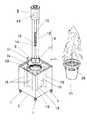
【図1】植木鉢を取り外して示す植木スタンドの斜視図
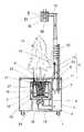
【図2】植木スタンドの断面図
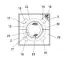
【図3】外箱の断面平面図
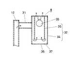
【図4】植木スタンドの一部の分解斜視図
【図5】ランプケースの断面図
【符号の説明】
2 外箱
9 空気パイプ
15 水容器
16 吸気管
18 ファン
21 植木鉢
23 吸水布
24 シール
25 水孔
26 空気孔
27 遮蔽鍔
33 白熱灯[0001]
BACKGROUND OF THE INVENTION
The present invention relates to a plant stand used for growing a plant having roots indoors, and particularly for a plant having a function of purifying indoor air by allowing air to pass through the soil holding the roots. It relates to a suitable garden stand.
[0002]
[Prior art]
It is known that microorganisms that grow in the roots of certain plants or in soil planted with certain plants decompose or destroy toxins in the air, such as those of Wolverton et al. (1984). Research paper "Foliage plants for removing indoor air pollutants from energy-efficient houses" Economi Botany 38 (2) 224-228 and C. Wolverton and J.W. D. A research paper by Wolverton (1993), "Plants and soil microorganisms: Removal of formaldehyde, xylene and ammonia from the indoor environment," Mississippi Academy of Sciences 41 (2) 99-105.
[0003]
In order to effectively use the air purification action of the soil where these plants are planted, in order to maintain the healthy growth of the plants, the fertilizer and water should be properly managed with a small amount of work, and the plants were planted It is necessary to appropriately prevent the growth of fungi and downy mildew pathogens that are harmful to plants in the soil, and to appropriately pass room air through the soil in which the plants are planted.
[0004]
As a planting stand that takes these needs into consideration, a sealed water container for supplying water to the soil packed in a conventional flower pot, an air pipe with an intake pipe inserted into the soil in the flower pot, and this A plant stand having a fan for flowing air in an air pipe and an incandescent lamp arranged at the outlet of the air pipe has been proposed. The sealed water container has a function to maintain normal water for a long time and supply it to the soil in the flowerpot. The air flow in the air pipe with the intake pipe inserted into the soil actively purifies the indoor air. It has a function of passing through soil having an action. The incandescent lamp also supplies light necessary for photosynthesis to plants planted in flowerpots, and heats the exhaust from the air pipe with the heat of the incandescent lamp, thereby sterilizing harmful pathogens contained in the exhausted air. It has.
[0005]
[Problems to be solved by the invention]
If the plant pot does not have to be large, there is a plant with the best function against all air pollution in the room, and the plant is very sturdy and does not wither or decay, Conventional devices are sufficiently practical. However, since the garden stand is actually placed indoors, it is required that the installation space is small and that a favorable appearance is provided. In addition, plants may be deteriorated or withered due to inadequate management or with a natural life span, and depending on the type of indoor air pollution, new plants suitable for purification may be found. In such a case, it is necessary to replace the plants on the plant stand.
[0006]
In the conventional device described above, the intake pipe is inserted in the flower pot, so when trying to plant a new plant, the intake pipe gets in the way and the roots of the plant cannot be greatly expanded in the flower pot, and therefore more Requires a large flowerpot. Moreover, since the plant after planting spreads the root around the intake pipe, when the plant is taken out, the root is damaged or the soil is scattered. In addition, since the intake pipe is inserted into the soil in the flower pot, if the plant is exchanged for every flower pot, the intake pipe must also be replaced, and a large number of intake pipes are required. For these reasons, the conventional plant stand for this kind of plant requires high attention for maintenance and management, and there is a problem that the replacement work of the plant is troublesome.
[0007]
It is an object of the present invention to provide a plant stand for a plant having a function of purifying indoor air, which can reduce the installation space and can be replaced by an extremely simple operation.
[0008]
[Means for Solving the Problems]
The plant stand according to
[0009]
When the soil is put into the
[0010]
The invention according to
[0011]
The
[0012]
Invention of
[0013]
In this kind of plant stand, when the
[0014]
The invention described in
[0015]
It is effective to provide a light source for illuminating the plant planted in the flower pot and promoting its photosynthesis so that the plant stand is equipped with the above-described conventional device. As described above, this light source can also be used to sterilize the air discharged into the room. The pillar supporting the light source is formed of a hollow pillar, and this pillar is used as an air pipe for guiding the exhaust air around the light source. By making the
[0016]
DETAILED DESCRIPTION OF THE INVENTION
Embodiments of the present invention will be described below with reference to the drawings illustrating examples. As shown in FIG.1 and FIG.2, the garden stand is provided with the
[0017]
The
[0018]
As shown in FIGS. 2 and 3, the
[0019]
A
[0020]
As shown inFIGS. 1 and 4, the
[0021]
A
[0022]
The upper surface of the
[0023]
The upper end of the
[0024]
A
[0025]
In the planting stand, when the
[Brief description of the drawings]
[Fig. 1] Perspective view of a plant stand with the flower pot removed [Fig. 2] Cross section of the plant stand [Fig. 3] Cross sectional plan view of the outer box [Fig. 4] An exploded perspective view of a part of the plant stand [Fig. Cross section of lamp case 【Explanation of symbols】
2
15 water container
16 Intake pipe
18 fans
21 Flowerpot
23 Absorbent cloth
24 seal
25 water holes
26 Air holes
27 Shield
33 Incandescent light
Claims (4)
Translated fromJapanesePriority Applications (2)
| Application Number | Priority Date | Filing Date | Title |
|---|---|---|---|
| JP35177498AJP4262811B2 (en) | 1998-12-10 | 1998-12-10 | Garden stand |
| US09/346,421US6230437B1 (en) | 1998-12-10 | 1999-07-01 | Plant stand |
Applications Claiming Priority (1)
| Application Number | Priority Date | Filing Date | Title |
|---|---|---|---|
| JP35177498AJP4262811B2 (en) | 1998-12-10 | 1998-12-10 | Garden stand |
Publications (2)
| Publication Number | Publication Date |
|---|---|
| JP2000166388A JP2000166388A (en) | 2000-06-20 |
| JP4262811B2true JP4262811B2 (en) | 2009-05-13 |
Family
ID=18419529
Family Applications (1)
| Application Number | Title | Priority Date | Filing Date |
|---|---|---|---|
| JP35177498AExpired - LifetimeJP4262811B2 (en) | 1998-12-10 | 1998-12-10 | Garden stand |
Country Status (2)
| Country | Link |
|---|---|
| US (1) | US6230437B1 (en) |
| JP (1) | JP4262811B2 (en) |
Families Citing this family (46)
| Publication number | Priority date | Publication date | Assignee | Title |
|---|---|---|---|---|
| US6477805B2 (en)* | 2001-03-08 | 2002-11-12 | Larry Austin Ware | Plant growth unit |
| US6615542B2 (en) | 2001-11-14 | 2003-09-09 | Larry Austen Ware | Plant growth unit |
| FR2837723A1 (en)* | 2002-03-28 | 2003-10-03 | Serge Sandzer | NATURAL FILTER SYSTEM FOR THE ELIMINATION OF CHEMICAL POLLUTANTS PRESENT IN THE INDOOR AIR OF BUILDINGS AND DWELLINGS |
| JP4155805B2 (en)* | 2002-05-27 | 2008-09-24 | 株式会社アクトリー | A flower stand having an air purification function and its flower pot |
| GB0225230D0 (en)* | 2002-10-30 | 2002-12-11 | Univ Guelph | Plant base system for abatement of gaseous ammonia contamination |
| JP3783036B2 (en)* | 2002-07-30 | 2006-06-07 | 独立行政法人農業・生物系特定産業技術研究機構 | Microgravity environment control device, plant cultivation device, animal breeding device, microgravity environment control method, plant cultivation method, animal breeding method, and breeding method |
| US6964130B1 (en) | 2003-02-21 | 2005-11-15 | Hartelius Mark E | Combination planter and step-light |
| US7331459B2 (en)* | 2004-08-17 | 2008-02-19 | Jason Hilbourne | Connectible pizza spacer |
| JP4812684B2 (en)* | 2007-04-26 | 2011-11-09 | 株式会社 欧倫ホーム | Air cleaner |
| US7735800B2 (en) | 2007-06-08 | 2010-06-15 | Fiskars Brands, Inc. | Adaptable planter mounting system |
| US7699487B2 (en)* | 2007-09-28 | 2010-04-20 | Schafer Steven R | Telescopic light base for coupling to diverse plant containers |
| CN101896062A (en)* | 2007-10-10 | 2010-11-24 | 拉博集团股份公司 | Biological air filter |
| US20090206046A1 (en)* | 2008-02-14 | 2009-08-20 | Fiskars Brands, Inc. | Adjustable stand for a planter |
| US9032665B2 (en)* | 2008-03-14 | 2015-05-19 | INKA Biospheric Systems | Aquaponic vertical garden with integrated air channel for plant-based air filtration |
| WO2010033423A1 (en)* | 2008-09-19 | 2010-03-25 | Martin Mittelmark | Micro-irrigation device, system, and method for plant-based cleaning of indoor air and filter bed bioregeneration |
| US8291639B2 (en)* | 2009-09-09 | 2012-10-23 | S and E Properties, Inc. | Growing system for hydroponics and/or aeroponics |
| CA2828602A1 (en) | 2010-03-16 | 2011-09-22 | Martin Mittelmark | Plant air purification enclosure apparatus and method |
| US20120090256A1 (en)* | 2010-10-14 | 2012-04-19 | Andrews Robin D | Three dimensional tiled deck accessories |
| KR101167447B1 (en) | 2011-02-18 | 2012-07-19 | 권순일 | Flowerpot comprising lighting device |
| FI20110247A0 (en) | 2011-07-22 | 2011-07-22 | Niko Rainer Jaervinen | Plant-based biofilter for removal of air-based volatile organic compounds and microbes |
| KR101136628B1 (en)* | 2011-09-15 | 2012-04-20 | 김달우 | Home cultivating apparatus capable of cleaning air |
| CN104025951A (en)* | 2013-03-07 | 2014-09-10 | 翁正祥 | Wall-mounted type plant air purifier |
| CN103299849B (en)* | 2013-05-31 | 2015-01-07 | 立宝(清远)实业有限公司 | Plant air purifier and system thereof |
| US9392755B1 (en) | 2013-08-21 | 2016-07-19 | Claudia Lantis | Method and apparatus for watering and supporting a plant |
| TWM481375U (en)* | 2014-02-19 | 2014-07-01 | zhen-xin Lin | Air cleaning device |
| US20150289452A1 (en)* | 2014-03-14 | 2015-10-15 | Yale University | Modular Living Green Wall System to Provide Heat Rejection |
| USD714993S1 (en)* | 2014-05-02 | 2014-10-07 | Thomas E Clendening | Indoor plant growing apparatus |
| US9642314B1 (en) | 2014-06-05 | 2017-05-09 | Lijo Joseph | Plant stand with multiple lighting devices and plant holders |
| CN104586159B (en)* | 2015-01-05 | 2016-06-29 | 惠州莫思特科技有限公司 | Illumination articles holding table |
| CN104705104B (en)* | 2015-03-06 | 2016-08-03 | 衢州图艺工业设计有限公司 | A kind of combined blowing flowerpot |
| WO2016191596A1 (en) | 2015-05-26 | 2016-12-01 | Delos Living Llc | Green wall modular system |
| JP2017006564A (en)* | 2015-06-25 | 2017-01-12 | 太平洋セメント株式会社 | Air purification device and air purification method |
| CN104969849B (en)* | 2015-07-17 | 2017-07-28 | 南京万荣园林实业有限公司 | Environmental indoor air-purification device |
| CN106440023A (en)* | 2016-01-10 | 2017-02-22 | 河北航安智能科技有限公司 | Green plant air purifier |
| CN105961070A (en)* | 2016-07-04 | 2016-09-28 | 胡玥 | Flowerpot assembly |
| WO2018111203A1 (en)* | 2016-12-14 | 2018-06-21 | Muanchart Mankaew | Air movement control and air source device for cultivation |
| US11540452B2 (en) | 2016-12-14 | 2023-01-03 | Mankaew MUANCHART | Air movement control and air source device for cultivation |
| CN106678976B (en)* | 2017-01-19 | 2022-07-12 | 中山市众成包装制品有限公司 | Indoor planter utilizing fan to accelerate air flow |
| WO2018211307A1 (en)* | 2017-03-22 | 2018-11-22 | Laboratori Fabrici S.R.L. | Air purifier |
| US11298655B2 (en) | 2017-11-08 | 2022-04-12 | Biome, Inc. | Wall-mounted plant-based air purification system |
| SG11202103534SA (en) | 2018-10-08 | 2021-05-28 | Gardyn Inc | Plant growth container |
| US11051462B2 (en)* | 2018-12-15 | 2021-07-06 | Beverly Lewis-Malone | Stain proof gardening container |
| IT201900001455A1 (en) | 2019-02-01 | 2020-08-01 | Laboratori Fabrici Srl | AIR PURIFIER |
| USD922249S1 (en) | 2019-07-01 | 2021-06-15 | Gardyn Inc. | Pod for a produce-growing system |
| GB2601288B (en)* | 2020-09-08 | 2023-01-11 | City Air Tech Limited | Air cleaning system and method |
| USD1004477S1 (en)* | 2020-09-29 | 2023-11-14 | Gerald Johnson | Adaptor for a planter |
Family Cites Families (3)
| Publication number | Priority date | Publication date | Assignee | Title |
|---|---|---|---|---|
| US5347751A (en)* | 1993-10-06 | 1994-09-20 | Frans Carpay | Modular plant stand |
| US5397382A (en)* | 1993-10-18 | 1995-03-14 | Alliance Research And Manufacturing Corporation | Bio regenerating air filter |
| US6006471A (en)* | 1998-05-07 | 1999-12-28 | Sun; En-Jang | Air-cleaning ecosystem apparatus |
- 1998
- 1998-12-10JPJP35177498Apatent/JP4262811B2/ennot_activeExpired - Lifetime
- 1999
- 1999-07-01USUS09/346,421patent/US6230437B1/ennot_activeExpired - Fee Related
Also Published As
| Publication number | Publication date |
|---|---|
| JP2000166388A (en) | 2000-06-20 |
| US6230437B1 (en) | 2001-05-15 |
Similar Documents
| Publication | Publication Date | Title |
|---|---|---|
| JP4262811B2 (en) | Garden stand | |
| KR100785930B1 (en) | Automated Greenhouse System for Indoor Air Purification | |
| KR100858993B1 (en) | Indoor garden system for air cleaning using moss wall and indoor plants | |
| KR101429678B1 (en) | All-in-one indoor environmental improvement devices | |
| KR101790143B1 (en) | Fabricated Multi-Function Flowerpot Assembly and Flowerpot and strut with the Same | |
| KR100377569B1 (en) | Interior garden with air cleaning function | |
| JP2008267684A (en) | Function-improving installation structure of air conditioner outdoor unit | |
| JP4155805B2 (en) | A flower stand having an air purification function and its flower pot | |
| KR102202733B1 (en) | Apparatus of growing vegetation | |
| KR20190064175A (en) | Air purifier | |
| CN110352845A (en) | A kind of family's column plant ultrasound mist training device capable of purifying air | |
| CN104707473B (en) | A kind of plant air purifier | |
| CN204619738U (en) | A kind of plant air purifier | |
| KR100943824B1 (en) | A flowerpot | |
| KR102271415B1 (en) | Indoor air purifying device using green plants | |
| JP4203142B2 (en) | Air purifier using the workings of plants | |
| CN214546083U (en) | Be used for quercus mongolica seedling culture container device | |
| KR20100129974A (en) | Hydroponic Cultivation Unit and Modular Flower Pot Using the Same | |
| KR200400928Y1 (en) | Air purifier of hydroponic culture | |
| JP2995275B2 (en) | Irrigation method for potted plants and planter used therefor | |
| KR200416056Y1 (en) | I incubator | |
| CN2819093Y (en) | Vegetable air filter | |
| JP2004020137A (en) | Air cleaner | |
| KR102180097B1 (en) | flowerpot with lamp | |
| JP3043873U (en) | Air cleaner |
Legal Events
| Date | Code | Title | Description |
|---|---|---|---|
| A621 | Written request for application examination | Free format text:JAPANESE INTERMEDIATE CODE: A621 Effective date:20051028 | |
| A977 | Report on retrieval | Free format text:JAPANESE INTERMEDIATE CODE: A971007 Effective date:20070522 | |
| A131 | Notification of reasons for refusal | Free format text:JAPANESE INTERMEDIATE CODE: A131 Effective date:20070828 | |
| A521 | Request for written amendment filed | Free format text:JAPANESE INTERMEDIATE CODE: A523 Effective date:20071026 | |
| A131 | Notification of reasons for refusal | Free format text:JAPANESE INTERMEDIATE CODE: A131 Effective date:20081028 | |
| A521 | Request for written amendment filed | Free format text:JAPANESE INTERMEDIATE CODE: A523 Effective date:20081225 | |
| TRDD | Decision of grant or rejection written | ||
| A01 | Written decision to grant a patent or to grant a registration (utility model) | Free format text:JAPANESE INTERMEDIATE CODE: A01 Effective date:20090127 | |
| A01 | Written decision to grant a patent or to grant a registration (utility model) | Free format text:JAPANESE INTERMEDIATE CODE: A01 | |
| A61 | First payment of annual fees (during grant procedure) | Free format text:JAPANESE INTERMEDIATE CODE: A61 Effective date:20090210 | |
| FPAY | Renewal fee payment (event date is renewal date of database) | Free format text:PAYMENT UNTIL: 20120220 Year of fee payment:3 | |
| R150 | Certificate of patent or registration of utility model | Free format text:JAPANESE INTERMEDIATE CODE: R150 | |
| FPAY | Renewal fee payment (event date is renewal date of database) | Free format text:PAYMENT UNTIL: 20130220 Year of fee payment:4 | |
| R250 | Receipt of annual fees | Free format text:JAPANESE INTERMEDIATE CODE: R250 | |
| R250 | Receipt of annual fees | Free format text:JAPANESE INTERMEDIATE CODE: R250 | |
| R250 | Receipt of annual fees | Free format text:JAPANESE INTERMEDIATE CODE: R250 | |
| EXPY | Cancellation because of completion of term |