JP4262595B2 - Expandable orthopedic device - Google Patents
Expandable orthopedic deviceDownload PDFInfo
- Publication number
- JP4262595B2 JP4262595B2JP2003513442AJP2003513442AJP4262595B2JP 4262595 B2JP4262595 B2JP 4262595B2JP 2003513442 AJP2003513442 AJP 2003513442AJP 2003513442 AJP2003513442 AJP 2003513442AJP 4262595 B2JP4262595 B2JP 4262595B2
- Authority
- JP
- Japan
- Prior art keywords
- spline
- support arm
- splines
- collar
- actuator
- Prior art date
- Legal status (The legal status is an assumption and is not a legal conclusion. Google has not performed a legal analysis and makes no representation as to the accuracy of the status listed.)
- Expired - Fee Related
Links
- 230000000399orthopedic effectEffects0.000titledescription3
- 210000000988bone and boneAnatomy0.000claimsabstractdescription77
- 230000000087stabilizing effectEffects0.000claimsabstractdescription5
- 238000000034methodMethods0.000claimsdescription36
- 238000004519manufacturing processMethods0.000claimsdescription8
- 230000033001locomotionEffects0.000claimsdescription6
- 238000005520cutting processMethods0.000claimsdescription4
- 230000000149penetrating effectEffects0.000claims1
- 210000000689upper legAnatomy0.000description27
- 208000010392Bone FracturesDiseases0.000description19
- 210000001185bone marrowAnatomy0.000description19
- 238000003780insertionMethods0.000description14
- 230000037431insertionEffects0.000description14
- 210000002303tibiaAnatomy0.000description12
- 230000006378damageEffects0.000description9
- 210000002758humerusAnatomy0.000description9
- 239000000463materialSubstances0.000description6
- 238000013459approachMethods0.000description4
- 210000002745epiphysisAnatomy0.000description4
- 210000003240portal veinAnatomy0.000description4
- 239000007787solidSubstances0.000description4
- 0C1C2C1C*C2Chemical compoundC1C2C1C*C20.000description3
- 210000003484anatomyAnatomy0.000description3
- 210000004027cellAnatomy0.000description3
- 210000004349growth plateAnatomy0.000description3
- 230000008439repair processEffects0.000description3
- 238000001356surgical procedureMethods0.000description3
- 238000003466weldingMethods0.000description3
- 208000006735PeriostitisDiseases0.000description2
- 208000027418Wounds and injuryDiseases0.000description2
- 238000005452bendingMethods0.000description2
- 230000008901benefitEffects0.000description2
- 238000007796conventional methodMethods0.000description2
- 230000008878couplingEffects0.000description2
- 238000010168coupling processMethods0.000description2
- 238000005859coupling reactionMethods0.000description2
- 208000014674injuryDiseases0.000description2
- 239000007788liquidSubstances0.000description2
- 238000002595magnetic resonance imagingMethods0.000description2
- 229910052751metalInorganic materials0.000description2
- 239000002184metalSubstances0.000description2
- 230000001575pathological effectEffects0.000description2
- 210000003460periosteumAnatomy0.000description2
- 230000008569processEffects0.000description2
- 238000011321prophylaxisMethods0.000description2
- 230000006641stabilisationEffects0.000description2
- 238000011105stabilizationMethods0.000description2
- 239000010935stainless steelSubstances0.000description2
- 210000001519tissueAnatomy0.000description2
- 206010031252OsteomyelitisDiseases0.000description1
- 229910001069Ti alloyInorganic materials0.000description1
- RTAQQCXQSZGOHL-UHFFFAOYSA-NTitaniumChemical compound[Ti]RTAQQCXQSZGOHL-UHFFFAOYSA-N0.000description1
- 229910045601alloyInorganic materials0.000description1
- 239000000956alloySubstances0.000description1
- 239000000560biocompatible materialSubstances0.000description1
- 230000036770blood supplyEffects0.000description1
- 210000002449bone cellAnatomy0.000description1
- 210000003557bones of lower extremityAnatomy0.000description1
- 238000011109contaminationMethods0.000description1
- 210000002436femur neckAnatomy0.000description1
- 239000012467final productSubstances0.000description1
- 210000001981hip boneAnatomy0.000description1
- 238000003384imaging methodMethods0.000description1
- 238000002513implantationMethods0.000description1
- 230000009545invasionEffects0.000description1
- 210000003127kneeAnatomy0.000description1
- 238000003698laser cuttingMethods0.000description1
- 210000001872metatarsal boneAnatomy0.000description1
- 238000012986modificationMethods0.000description1
- 230000004048modificationEffects0.000description1
- 229910001000nickel titaniumInorganic materials0.000description1
- HLXZNVUGXRDIFK-UHFFFAOYSA-Nnickel titaniumChemical compound[Ti].[Ti].[Ti].[Ti].[Ti].[Ti].[Ti].[Ti].[Ti].[Ti].[Ti].[Ni].[Ni].[Ni].[Ni].[Ni].[Ni].[Ni].[Ni].[Ni].[Ni].[Ni].[Ni].[Ni].[Ni]HLXZNVUGXRDIFK-UHFFFAOYSA-N0.000description1
- 230000002093peripheral effectEffects0.000description1
- 229920000642polymerPolymers0.000description1
- 238000011084recoveryMethods0.000description1
- 230000009467reductionEffects0.000description1
- 230000008929regenerationEffects0.000description1
- 238000011069regeneration methodMethods0.000description1
- 238000011160researchMethods0.000description1
- 239000012858resilient materialSubstances0.000description1
- 230000000979retarding effectEffects0.000description1
- 238000007790scrapingMethods0.000description1
- 229910001285shape-memory alloyInorganic materials0.000description1
- 239000003381stabilizerSubstances0.000description1
- 229910001220stainless steelInorganic materials0.000description1
- 229910001256stainless steel alloyInorganic materials0.000description1
- 238000002560therapeutic procedureMethods0.000description1
- 239000010936titaniumSubstances0.000description1
- 229910052719titaniumInorganic materials0.000description1
- 238000011282treatmentMethods0.000description1
Images


Classifications
- A—HUMAN NECESSITIES
- A61—MEDICAL OR VETERINARY SCIENCE; HYGIENE
- A61B—DIAGNOSIS; SURGERY; IDENTIFICATION
- A61B17/00—Surgical instruments, devices or methods
- A61B17/56—Surgical instruments or methods for treatment of bones or joints; Devices specially adapted therefor
- A61B17/58—Surgical instruments or methods for treatment of bones or joints; Devices specially adapted therefor for osteosynthesis, e.g. bone plates, screws or setting implements
- A61B17/68—Internal fixation devices, including fasteners and spinal fixators, even if a part thereof projects from the skin
- A61B17/72—Intramedullary devices, e.g. pins or nails
- A61B17/7233—Intramedullary devices, e.g. pins or nails with special means of locking the nail to the bone
- A61B17/7258—Intramedullary devices, e.g. pins or nails with special means of locking the nail to the bone with laterally expanding parts, e.g. for gripping the bone
- A61B17/7266—Intramedullary devices, e.g. pins or nails with special means of locking the nail to the bone with laterally expanding parts, e.g. for gripping the bone with fingers moving radially outwardly
- A—HUMAN NECESSITIES
- A61—MEDICAL OR VETERINARY SCIENCE; HYGIENE
- A61B—DIAGNOSIS; SURGERY; IDENTIFICATION
- A61B17/00—Surgical instruments, devices or methods
- A61B17/56—Surgical instruments or methods for treatment of bones or joints; Devices specially adapted therefor
- A61B17/58—Surgical instruments or methods for treatment of bones or joints; Devices specially adapted therefor for osteosynthesis, e.g. bone plates, screws or setting implements
- A61B17/68—Internal fixation devices, including fasteners and spinal fixators, even if a part thereof projects from the skin
- A61B17/74—Devices for the head or neck or trochanter of the femur
- A61B17/742—Devices for the head or neck or trochanter of the femur having one or more longitudinal elements oriented along or parallel to the axis of the neck
- A61B17/744—Devices for the head or neck or trochanter of the femur having one or more longitudinal elements oriented along or parallel to the axis of the neck the longitudinal elements coupled to an intramedullary nail
- A—HUMAN NECESSITIES
- A61—MEDICAL OR VETERINARY SCIENCE; HYGIENE
- A61B—DIAGNOSIS; SURGERY; IDENTIFICATION
- A61B17/00—Surgical instruments, devices or methods
- A61B17/56—Surgical instruments or methods for treatment of bones or joints; Devices specially adapted therefor
- A61B17/58—Surgical instruments or methods for treatment of bones or joints; Devices specially adapted therefor for osteosynthesis, e.g. bone plates, screws or setting implements
- A61B17/68—Internal fixation devices, including fasteners and spinal fixators, even if a part thereof projects from the skin
- A61B17/74—Devices for the head or neck or trochanter of the femur
- A61B17/742—Devices for the head or neck or trochanter of the femur having one or more longitudinal elements oriented along or parallel to the axis of the neck
- A61B17/746—Devices for the head or neck or trochanter of the femur having one or more longitudinal elements oriented along or parallel to the axis of the neck the longitudinal elements coupled to a plate opposite the femoral head
- A—HUMAN NECESSITIES
- A61—MEDICAL OR VETERINARY SCIENCE; HYGIENE
- A61B—DIAGNOSIS; SURGERY; IDENTIFICATION
- A61B17/00—Surgical instruments, devices or methods
- A61B17/56—Surgical instruments or methods for treatment of bones or joints; Devices specially adapted therefor
- A61B17/58—Surgical instruments or methods for treatment of bones or joints; Devices specially adapted therefor for osteosynthesis, e.g. bone plates, screws or setting implements
- A61B17/68—Internal fixation devices, including fasteners and spinal fixators, even if a part thereof projects from the skin
- A61B17/72—Intramedullary devices, e.g. pins or nails
- A61B17/7291—Intramedullary devices, e.g. pins or nails for small bones, e.g. in the foot, ankle, hand or wrist
- A—HUMAN NECESSITIES
- A61—MEDICAL OR VETERINARY SCIENCE; HYGIENE
- A61B—DIAGNOSIS; SURGERY; IDENTIFICATION
- A61B17/00—Surgical instruments, devices or methods
- A61B2017/00831—Material properties
- A61B2017/00867—Material properties shape memory effect
Landscapes
- Health & Medical Sciences (AREA)
- Orthopedic Medicine & Surgery (AREA)
- Surgery (AREA)
- Life Sciences & Earth Sciences (AREA)
- Heart & Thoracic Surgery (AREA)
- Animal Behavior & Ethology (AREA)
- Engineering & Computer Science (AREA)
- Biomedical Technology (AREA)
- Neurology (AREA)
- Medical Informatics (AREA)
- Molecular Biology (AREA)
- Nuclear Medicine, Radiotherapy & Molecular Imaging (AREA)
- General Health & Medical Sciences (AREA)
- Public Health (AREA)
- Veterinary Medicine (AREA)
- Surgical Instruments (AREA)
- Prostheses (AREA)
- Orthopedics, Nursing, And Contraception (AREA)
Abstract
Description
Translated fromJapanese本発明は、審査継続中の1999年10月22日出願の米国特許出願09/426,563号の部分継続出願であり、これは1998年10月26日出願の米国暫定出願60/105,593号と、2000年10月19日に出願され、2001年4月26日に公開された国際特許出願PCT/IL00/00666号の利益を享受して、2001年7月17日に米国特許6,261,289号として特許されている。これらは、明細書中に記載されている。 The present invention is a continuation-in-part of U.S. Patent Application 09 / 426,563, filed October 22, 1999, which is pending examination, which is US Provisional Application 60 / 105,593, filed Oct. 26, 1998. And the benefit of International Patent Application PCT / IL00 / 00666 filed on October 19, 2000 and published on April 26, 2001, on July 17, 2001, US Pat. Patent No. 261,289. These are described in the specification.
発明の利用分野
本発明は、骨折の外科的処置、および、病的な骨の予防的治療に利用する整形外科用装置に関するものであり、特に、拡開可能な骨髄内装置、及びこの装置の製造方法と使用方法に関する。FIELD OF THE INVENTION The present invention relates to an orthopedic device for use in surgical procedures for fractures and prophylactic treatment of pathological bone, and in particular, an expandable intramedullary device and the device. The present invention relates to a manufacturing method and a usage method.
発明の背景
四肢の骨の損傷は、骨の表面に横たわらせるプレート、損傷した骨の骨髄の管内を通す釘、及び/又は損傷した骨の端部を互いに固定するスクリュなどの、内部固定装置を用いて処置されている。これらの内部固定装置は、ほどよい構造的な硬さ及び/又は損傷した骨に対する骨細胞を刺激するのに必要ないくらかの圧力と矛盾することのない安定性を提供するものである。BACKGROUND OF THE INVENTION Limb bone damage is caused by internal fixation, such as a plate that lies on the surface of the bone, a nail that passes through the bone marrow of the damaged bone, and / or a screw that secures the ends of the damaged bone together. Treated with a device. These internal fixation devices provide reasonable structural hardness and / or stability consistent with some pressure required to stimulate bone cells against damaged bone.
骨髄内固定方法は、長骨の損傷を処置する伝統的な手順であり、骨髄内釘を用いて骨膜を傷つけることなく、骨の損傷を固定する。このような方法は、閉態様で完行され、破損した骨は治癒するまでの間、(体重がかかることも含めて)機能的に使用されることになる。この骨髄内釘を挿入する外科的アプローチは、各骨によって若干異なり、外科の文献にきちんと記載されている。 The intramedullary fixation method is a traditional procedure for treating long bone damage and uses an intramedullary nail to fix bone damage without damaging the periosteum. Such a method is completed in a closed manner and the broken bone will be used functionally (including weight) until it heals. The surgical approach to insert this intramedullary nail is slightly different for each bone and is well documented in the surgical literature.
従来の骨髄内固定方法に伴ういくつかの問題点として、回転安定性の欠如、いくつかの損傷型における損傷サイトの崩壊、及び/又は好ましくない釘の詰まり(backup)などがある。さらに、実際の典型的な骨の形状がいくらかカーブしているにもかかわらず、損傷した骨の修復に使用される骨髄内釘は、一般的にまっすぐである。更に、骨髄内固定方法は、釘との連動式のスクリュを導入しており、これが不利益をもたらす。特に、従来の長骨用骨髄内固定釘は、硬質構造(中空またはむく)を有しており、その遠位において、骨壁を介して横方向に設けられた別のスクリュによって、釘自体に連結するように構成されている。この更なるステップにより、通常、手術の時間が長くなり、手術がより複雑なものになると共に、皮膚を余分に切開しなければならず、及び/又は、画像増輝度管(X線)を長時間使用しなければならなくなる。さらに、スクリュから好ましくない骨端部間のギャップが生じ、このスクリュは新たな手術によって除去しない限りそこに残ってしまう。また、結果として生じる構造が曲がりにくいものであり、所定の場合に所望の弾性に欠けることになる。破損箇所が汚染されている場合は、損傷箇所を洗浄しても金属性の骨髄内釘が管全体に汚染を伝はんし、骨の感染を引き起こす。 Some problems with conventional intramedullary fixation methods include lack of rotational stability, collapse of damaged sites in some types of damage, and / or undesirable nail clogging. Furthermore, the intramedullary nails used to repair damaged bone are generally straight, despite the fact that the actual typical bone shape is somewhat curved. Furthermore, the intramedullary fixation method introduces an interlocking screw with a nail, which is disadvantageous. In particular, the conventional long bone intramedullary nail has a hard structure (hollow or peeled), and at its distal end, a separate screw provided laterally through the bone wall to the nail itself. It is comprised so that it may connect. This further step usually increases the time of the operation, makes the operation more complicated, requires an extra incision in the skin, and / or lengthens the image intensifier tube (X-ray). You will have to use it for hours. In addition, an undesired gap between the bone ends is created from the screw, which remains there unless removed by a new operation. Also, the resulting structure is difficult to bend and lacks the desired elasticity in certain cases. If the damaged area is contaminated, the metallic intramedullary nail will transmit contamination throughout the tube and cause bone infection even if the damaged area is cleaned.
骨髄内固定アプローチの最新の研究は、これらの問題のいくつかの解決する努力に取り組んでいる。例えば、PCT公開WO98/38918(Beyar)は、以下の3つの構造的なデザインを提唱している。(1)骨髄管内で拡開する固い金属シート;(2)遠位において周辺に連結されるリブを有するメッシュ構造;および(3)骨髄管内に挿入されると膨張する風船構造。これらのうち(1)と(2)は、骨の骨幹端内において安定した支持を提供しないことがある。特に、これらの構造は、骨髄管の骨幹セグメントの周辺部によってこれらの構造全体の伸びが限定されるため、両端部において伸びない。風船構造は、膨張する際に、骨への血液供給を妨げ、再生あるいは回復を妨げるため、有用性が限定され、及び/又は、一旦挿入されて膨張した後は、体積が確定するため、骨髄管の形状の変化に追随できないことがある。 The latest research on intramedullary fixation approaches is working on solving some of these problems. For example, PCT Publication WO 98/38918 (Beyer) proposes the following three structural designs: (1) a solid metal sheet that expands in the medullary canal; (2) a mesh structure with ribs connected to the periphery at the distal end; and (3) a balloon structure that expands when inserted into the medullary canal. Of these, (1) and (2) may not provide stable support within the metaphysis of bone. In particular, these structures do not extend at both ends because the overall extension of these structures is limited by the periphery of the diaphyseal segment of the medullary canal. The balloon structure, when inflated, impedes blood supply to the bone, impedes regeneration or recovery, so that its usefulness is limited and / or once inserted and inflated, the volume is determined, so that the bone marrow It may not be possible to follow changes in the shape of the tube.
Vicenziの米国特許第5,282,225号は、突出部(stub)で互いに連結された多数の伸縮性のある変形可能なステムを開示している。このステムは、損傷した骨の骨髄管に挿入されると、遠位が骨髄管の端部内に向けて外側に拡開して骨の中に食い込む。しかしながら、この装置は、受動的な装置であり、展開するときに自動的に拡開し、拡開をコントロールすることができない。さらに、この装置は骨髄管内で拡開せず、従って骨髄管壁に複数の接触点を提供するものではない。このため、Vicenziの構造は、損傷した骨の横平面と回転平面に沿った構造的な安定性が確実でない。 Vicenzi U.S. Pat. No. 5,282,225 discloses a number of elastically deformable stems connected together by stubs. When the stem is inserted into the bone marrow canal of a damaged bone, the distal portion extends outwardly into the end of the bone marrow canal and bites into the bone. However, this device is a passive device that automatically expands when deployed and cannot control the expansion. Furthermore, the device does not expand within the medullary canal and therefore does not provide multiple contact points on the medullary canal wall. For this reason, the structure of Vicenzi is not reliably structurally stable along the transverse and rotational planes of the damaged bone.
したがって、損傷した骨に安定性を提供し、及び/又は、安定性を確実にする骨髄内装置は有用であると考えられる。 Thus, an intramedullary device that provides stability to and / or ensures stability of damaged bone is considered useful.
発明の概要
本発明は、骨折の外科的処置、および、病的な骨の予防的治療に利用する整形外科用装置に関するものであり、特に、拡開可能な骨髄内の装置、及びこの装置の製造方法と使用方法に関する。SUMMARY OF THE INVENTION The present invention relates to an orthopedic device for use in surgical procedures for fractures and prophylactic treatment of pathological bone, and in particular, an expandable intramedullary device and the device. The present invention relates to a manufacturing method and a usage method.
本発明の第1の特徴とするところは、骨の安定化装置であり、第1及び第2の端部領域を有し、この領域間に長軸を規定する細長いボディを具える。第1の端部領域から複数のスプラインが延在しており、これらのスプラインは前記細長ボディの第1の端部領域に連結された第1の端部と、前記第1の端部領域から離れて位置する第2の端部を具え、これらのスプラインの第2の端部は、通常の軸方向に閉じた状態からほぼ横方向に拡開した状態へ誘導可能である。概スプラインに支持アームが連結されており、この支持アームにアクチュエータが連結されている。このアクチュエータは、前記細長ボディに対して軸方向において可動であり、支持アームを駆動して、スプラインの第2の端部を閉じた状態から拡開した状態に誘導する。 A first feature of the present invention is a bone stabilization device having an elongated body having first and second end regions and defining a major axis therebetween. A plurality of splines extend from the first end region, the splines extending from the first end region connected to the first end region of the elongate body and from the first end region. With a second end located remotely, the second ends of these splines can be guided from a normal axially closed state to a substantially laterally expanded state. A support arm is connected to the approximate spline, and an actuator is connected to the support arm. The actuator is movable in the axial direction with respect to the elongated body, and drives the support arm to guide the second end of the spline from a closed state to an expanded state.
一の実施例では、細長ボディが、近位側および遠位側端部領域間に延在する管腔を具える筒状シャフトであり、前記アクチュエータが管腔内に収納され、好ましくは互いに係合するネジ部にて前記筒状シャフトに摺動自在に連結された細長部材を具える。この細長部材と、支持アームにカラーが連結されている。好ましくは、細長部材は、ねじ部を具えており、前記カラーがネジ止めされて細長部材の筒状シャフトに対する回転が、カラーを軸方向に移動させ、この移動によって支持アームが前記スパイラルを、閉じた状態と拡開した状態間に誘導する。 In one embodiment, the elongate body is a cylindrical shaft with a lumen extending between the proximal and distal end regions, and the actuator is housed within the lumen and preferably engaged with each other. An elongate member slidably connected to the cylindrical shaft at a threaded portion is provided. A collar is connected to the elongated member and the support arm. Preferably, the elongated member has a threaded portion, and the collar is screwed and rotation of the elongated member with respect to the cylindrical shaft moves the collar in the axial direction, and this movement causes the support arm to close the spiral. Guiding between a raised state and an expanded state.
本発明の更なる特徴によれば、骨安定装置が第1及び第2の端部領域を具え、これらの領域間の長軸と、前記第1及び第2の端部領域間の中間領域を規定する細長ボディを具える。第1の複数のスプラインが前記第1の端部領域から延在しており、これらのスプラインは通常の軸方向における閉じた状態からほぼ横方向へ拡開した状態に誘導されうる。第2の複数のスプラインが細長ボディの先端領域から近位側端部領域へ延在しており、これらのスプラインは通常の軸方向における閉じた状態からほぼ横方向へ拡開した状態に誘導されうる。 According to a further feature of the present invention, the bone stabilizer includes first and second end regions, and a major axis between these regions and an intermediate region between the first and second end regions. It has an elongated body that regulates. A first plurality of splines extend from the first end region, and these splines can be guided from a closed state in the normal axial direction to a substantially laterally expanded state. A second plurality of splines extend from the distal end region of the elongated body to the proximal end region, and these splines are guided from a closed state in the normal axial direction to a substantially laterally expanded state. sell.
第1及び第2の複数の支持アームが前記第1及び第2の複数のスプラインにそれぞれ連結されており、アクチュエータがこの支持アームに連結されている。該アクチュエータは、細長ボディに対して軸方向に移動可能であり、前記第1及び第2の複数の支持アームに、前記スプラインを閉じた状態から拡開した状態に誘導させる。 First and second plurality of support arms are connected to the first and second plurality of splines, respectively, and an actuator is connected to the support arms. The actuator is movable in the axial direction with respect to the elongated body, and causes the first and second support arms to guide the spline from a closed state to an expanded state.
好ましくは、該細長ボディは近位側及び遠位側端部領域間に延在する管腔を具える筒状シャフトであり、アクチュエータが該管腔内に収納される細長部材を含む。第1および第2のカラーがこの細長部材と第1及び第2の複数の支持部材に、それぞれ連結されている。この細長部材の筒状シャフトに対する回転によって、第1及び第2のカラーを軸方向に移動させ、第1及び第2の複数の支持部材にスプラインを閉じた状態と拡開状態の間に誘導させる。 Preferably, the elongate body is a cylindrical shaft with a lumen extending between the proximal and distal end regions, and the actuator includes an elongate member received within the lumen. First and second collars are coupled to the elongate member and the first and second plurality of support members, respectively. By rotating the elongated member with respect to the cylindrical shaft, the first and second collars are moved in the axial direction, and the first and second support members are guided between the closed state and the expanded state. .
一の実施形態においては、第2の複数のスプラインが遠位になるように筒状シャフトの遠位側端部から延在している。細長部材は一方と他方が逆のねじパターンを有する第1及び第2のねじ部を具えていても良い。この逆ネジ構成により、細長部材の回転がカラーを反対方向に移動させる。従って、細長部材の第1方向における回転が、カラーを他方から離れる方向に移動させてスプラインを拡開し、一方細長部材を逆方向に回転させることによってカラーを他方に向けて移動させ、スプラインを閉じる。 In one embodiment, the second plurality of splines extend from the distal end of the tubular shaft so that it is distal. The elongate member may comprise first and second threaded portions, one and the other having opposite thread patterns. With this reverse thread configuration, the rotation of the elongated member moves the collar in the opposite direction. Thus, rotation of the elongated member in the first direction causes the collar to move away from the other to expand the spline, while rotating the elongated member in the opposite direction causes the collar to move toward the other, causing the spline to move. close.
代替の実施形態においては、第2の複数のスプラインが、筒状シャフトの中間領域に位置していても良い。上記に加えて、更なるスプラインのセットを筒状シャフトに沿って配置しても良い。従って、単一のアクチュエータを、単一の装置内の複数セットのスプラインを拡開させるのに使用しても良い。このスプラインは、形状及び/又は長さが異なっていても良く、この構成によって所定の形状を有する骨腔内に装置をインプラントすることが可能となる。 In an alternative embodiment, the second plurality of splines may be located in the middle region of the cylindrical shaft. In addition to the above, additional sets of splines may be placed along the cylindrical shaft. Thus, a single actuator may be used to expand multiple sets of splines within a single device. The splines may vary in shape and / or length, and this configuration allows the device to be implanted in a bone cavity having a predetermined shape.
更に、本発明の装置を軸方向において延長可能としても良い。例えば、装置の近位側端部から近位側へスプラインを越えて延在するものなどである。例えば、細長部材を、筒状シャフトの第1の端部においてスプラインを越えて近位側に延在させるか、筒状シャフト自体を延長可能としても良い。軸方向に孔を設けてこの孔に釘、スクリュ、あるいはその他の固定部材を収納して更なる横方向の支持を強化するようにしても良い。更に、インディケータ素子を装置から近位側に延在させるか、インプラント後の装置の位置がわかるように細長部材を延在させるように構成しても良い。 Furthermore, the device of the present invention may be extended in the axial direction. For example, one that extends beyond the spline from the proximal end of the device to the proximal side. For example, the elongated member may extend proximally beyond the spline at the first end of the cylindrical shaft, or the cylindrical shaft itself may be extendable. A hole may be provided in the axial direction, and a nail, a screw, or other fixing member may be accommodated in the hole to further enhance lateral support. Further, the indicator element may be extended proximally from the device, or the elongated member may be extended so that the position of the device after implantation is known.
本発明の更なる特徴は、骨安定用装置を製造する方法である。第1及び第2の端部領域を有し、これらの領域間の長軸を規定する細長筒状シャフトを提供する。前記筒状ボディの第1の端部領域に残って取り付けられている第1の端部と、この第1の端部に対して軸方向に配置された第2の端部を具えるスプラインが形成されており、第2の端部は前記筒状ボディに対して自在に移動可能である。好ましくは、スプラインは第1の端部領域において縦方向のスロットを作ることによって形成される。支持アームがスプラインに形成されており、この支持アームは、スプラインに対して自在に移動可能な第1の端部と、残りの部分においてスプラインに取り付けられている第2の端部を具える。好ましくは、この支持アームは各スプラインの部分的に切断された部分によって構成されている。 A further feature of the present invention is a method of manufacturing a bone stabilization device. An elongated cylindrical shaft is provided having first and second end regions and defining a major axis between these regions. A spline having a first end that remains attached to the first end region of the tubular body and a second end that is axially disposed relative to the first end. The second end portion is formed so as to be freely movable with respect to the cylindrical body. Preferably, the spline is formed by creating a longitudinal slot in the first end region. A support arm is formed on the spline, the support arm having a first end that is freely movable relative to the spline and a second end that is attached to the spline at the rest. Preferably, the support arm is constituted by a partially cut portion of each spline.
支持アームの第1の端部はアクチュエータに連結されていても良い。また、アクチュエータは支持アームを縦軸に対して外側に向けて横方向に止め付けるために筒状シャフトに対して軸方向に移動可能にしても良く、これによって、スプラインの第2の端部を外側に向けて横方向に方向付ける。好ましい実施形態においては、アクチュエータは細長部材と第1のカラーを具えている。この遅長部材は、筒状シャフトの軸管腔内に挿入され、第1のカラーは当該カラーが支持アームの第1の端部の近位側に位置するまで細長部材を越えてねじ込まれる。支持部材の第1の端部は、従って第1のカラーに連結される。 The first end of the support arm may be coupled to the actuator. The actuator may also be movable axially relative to the cylindrical shaft to hold the support arm laterally outward with respect to the longitudinal axis, thereby causing the second end of the spline to move. Orient laterally towards the outside. In a preferred embodiment, the actuator comprises an elongate member and a first collar. The retarding member is inserted into the axial lumen of the cylindrical shaft and the first collar is screwed over the elongated member until the collar is located proximal to the first end of the support arm. The first end of the support member is thus connected to the first collar.
好ましい実施例においては、筒状シャフトは管腔内に内ネジ部を具えており、細長部材が、筒状シャフトのねじ部に摺動可能に係合する外ネジ領域を有する。従って、細長部材の筒状シャフトに対する軸方向の動きは、細長部材のコントロールされた回転によるもの以外は制限されることになる。 In a preferred embodiment, the cylindrical shaft has an internal thread in the lumen, and the elongated member has an external thread region that slidably engages the threaded portion of the cylindrical shaft. Thus, the axial movement of the elongated member relative to the cylindrical shaft is limited except by the controlled rotation of the elongated member.
更に、第2のセット(あるいは追加セット)のスプラインと支持アームが筒状シャフトの他の領域、例えば第2の端部領域か、筒状シャフトの中間領域の上に形成されていても良い。この場合、第2のカラーが細長部材を越えて第2のカラーが第2のセットの支持アーム近位側になるまでネジがきられており、第2のセットの支持アームが第2のカラーに連結される。 Furthermore, the second set (or additional set) of splines and support arms may be formed on other areas of the cylindrical shaft, for example the second end area or on the intermediate area of the cylindrical shaft. In this case, the second collar is threaded over the elongated member until the second collar is proximal to the second set of support arms, and the second set of support arms is attached to the second collar. Connected.
本発明の装置は、従来の手順を用いて予め形成されている挿入門脈(entry portal)、例えば大腿骨などの骨の骨髄管を介して、スプラインをすぼめて挿入するようにしても良い。好ましくは、従来の方法を用いて当該門脈から骨の骨髄管内にガイドワイヤを最初に通して、骨の遠位セグメントまで延在させる。次いで、ガイドワイヤを先にしてこの装置を骨髄管内に通す。装置を挿入した後、ガイドワイヤを取り外す。 The device of the present invention may be inserted with a spline inserted through a bone marrow canal of a bone, such as the femur, which is preformed using conventional procedures. Preferably, a guidewire is first passed from the portal vein into the bone marrow canal of the bone using conventional methods to extend to the distal segment of the bone. The device is then passed through the medullary canal with the guide wire first. After inserting the device, the guide wire is removed.
一旦装置全体が骨髄管に挿入されたら、入り口内に差し込んだツールを用いてアクチュエータを駆動して、スプラインを拡開状態にし、スプラインが実質的に内部の骨、あるいは他の組織に係合するようにして、装置を骨に対して実質的に固定する。従って、この装置は装置がインプラントされている損傷した骨のセグメントが軸方向に動いたり、曲がったり、及び/又は他方に対して回転したりすることを防ぐ。また、より安定性が望まれる場合は、スプラインを越えて延在するようにしても良く、また、ネジ、釘などの固定装置を骨の中に横方向に導入したり、孔を介して骨のセグメントを更に固定するべく延長するようにしても良い。 Once the entire device has been inserted into the medullary canal, a tool inserted into the portal is used to drive the actuator, causing the spline to expand, and the spline substantially engages internal bone or other tissue. In this way, the device is substantially fixed to the bone. The device thus prevents the damaged bone segment in which the device is implanted from moving axially, bending and / or rotating relative to the other. If more stability is desired, it may extend beyond the spline, and a fixing device such as a screw or nail can be introduced laterally into the bone or bone can be inserted through the hole. These segments may be extended to further fix.
損傷が治癒した後は、従来の工程によって当該装置をはずすことができる。この取り外しの際には、アクチュエータを駆動するツールを挿入して、骨から取り外す前にスプラインを閉じた状態に戻す。 After the injury has healed, the device can be removed by conventional processes. During this removal, a tool that drives the actuator is inserted to return the spline to a closed state before removal from the bone.
本発明の他の目的および特徴を、図面を参照した以下の記載により明らかにする。 Other objects and features of the present invention will become apparent from the following description with reference to the drawings.
発明の詳細な説明
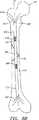
本発明は、大腿骨、頸骨、上腕骨などの様々な骨の損傷修復に使用することができる。背景として、図1乃至3を参照して、これらの骨の関連する特徴を以下に述べる。図1を参照すると、大腿骨100は、骨幹または中央シャフト102、近位骨幹端104、遠位骨幹端106、近位骨端またはヘッド108、遠位骨端110、大腿首部112、の6つの解剖学的領域に分けることができる。大腿骨100は、硬皮質114と、骨髄腔116で構成されている。本発明の目的用には、骨髄腔116は、骨髄管118を含んでおり、この骨髄管はシャフト102、近位及び遠位の骨幹端領域120、122、及び近位及び遠位の骨端124、126、の中央を貫通している。DETAILED DESCRIPTION OF THE INVENTION The present invention can be used to repair damage to various bones such as the femur, tibia, and humerus. By way of background, with reference to FIGS. 1-3, the relevant features of these bones are described below. Referring to FIG. 1, the
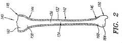
図2を参照すると、頸骨140は、骨幹または中央シャフト142、近位骨幹端144、遠位骨幹端146、近位骨端148、遠位骨端150の、5つの解剖学的領域に分けることができる。大腿骨100と同様に、頸骨140は、硬皮質152と、骨髄腔154で構成されている。本発明の目的用には、骨髄腔154は、骨髄管156を含んでおり、この骨髄管はシャフト142、近位及び遠位の骨幹端領域158、160、及び近位及び遠位の骨端162、164、の中央を貫通している。 Referring to FIG. 2, the
図3を参照すると、上腕骨170は、骨幹または中央シャフト172、近位骨幹端またはネック174、遠位骨幹端176、近位骨端またはヘッド178、遠位骨端180の、5つの解剖学的領域に分けることができる。大腿骨100や頸骨140と同様に、上腕骨170は、硬皮質182と、骨髄腔184で構成されている。本発明の目的用には、骨髄腔184は、骨髄管186を含んでおり、この骨髄管はシャフト172、近位及び遠位の骨幹端領域188、190、及び近位及び遠位の骨端192、194、の中央を貫通している。 Referring to FIG. 3, the humerus 170 has five anatomies: a shaft or
大腿骨100、頸骨140、および上腕骨170は、本発明の装置が使用される骨の一例にすぎない。本発明は、本発明の範囲から逸脱することなく、大腿骨100、頸骨140、上腕骨170以外の骨の損傷修復にも使用することができる。 The
大腿骨100、頸骨140、上腕骨170の骨髄管は、これらの骨のシャフトに沿ってほぼ均一な外周を有しているが、この骨随管はより大きな骨幹端と、骨端につながっている。従って、大腿骨100、頸骨140、上腕骨170の骨随腔は全体として、外周が異なり、端部における外周は、骨髄腔の中央部における外周より大きい。本発明の骨髄内装置は、リバーシブルに拡開することができる。すなわち、予めフォーマットされた形状にあわせて、骨髄管の内部形状に合致するように拡開することができる。本発明の骨髄内装置の使用により、損傷した骨の骨セグメントを回転方向に係止すると同時に、スクリューを使用することなく他の平面において十分な安定性を提供することができる。スクリュが必要な場合は、骨髄内装置と協働させて使用するようにしても良い。本装置は、侵襲を最小限に抑え、単一の切開、挿入門脈でインプラントすることができる。つなぎ合わせる骨に応じて、長さと型が異なる骨髄内装置が必要である。骨髄内装置は骨の外周の変化に適応する。 The bone marrow canals of the
骨髄内装置は、大腿骨、頸骨、上腕骨などの骨用の従来の骨髄内釘に使用されているのと同様の方法を用いて配置することができ、骨折整復後及び挿入制御後に必要なX線を最小限に抑えることができる。骨髄内装置はまた、ラッシュ型釘(Rush-type nails)の挿入に使用される通常のアプローチを介して、橈骨および腓骨に配置することもできる。子供の骨(骨端軟骨が開いている)の場合は、骨髄内装置は、門脈を介して近位骨端軟骨の下、および遠位骨端軟骨の上に、接続領域内にこれらを含めることなく、挿入することができる。例えば、大腿骨と頸骨を含む膝が融合している場合などには、長い骨髄内装置を使用することができる。例えば、中足骨、中手骨の骨折には、短い骨髄内装置を使用することができる。 Intramedullary devices can be deployed using methods similar to those used in conventional intramedullary nails for bones such as the femur, tibia, and humerus, and are required after fracture reduction and insertion control. X-rays can be minimized. Intramedullary devices can also be placed in the ribs and ribs via the usual approach used for the insertion of Rush-type nails. In the case of a child's bone (the epiphyseal cartilage is open), the intramedullary device places these in the connection area under the proximal epiphyseal cartilage and over the distal epiphyseal cartilage via the portal vein. Can be inserted without including. For example, a long intramedullary device can be used when the knee including the femur and the tibia are fused. For example, short intramedullary devices can be used for metatarsal and metacarpal fractures.
骨髄内装置の侵襲性を最小にするという特徴と共に、骨髄内アプローチは、一般的に破損した骨の骨膜に接触することなく行われる。更に、この骨髄内装置は、安定性と矛盾することなくより軽量であり、金属部分がより少ないため、後に照射するX線により好ましい視覚性を与える。また、組み合わせ強化治療として潜在的に使用されうる他のタイプのバイオメカニックな外的刺激と両存する。所定の合金を使用することによって、骨髄内装置を構成する材料は非磁性であり、MRI(磁気共鳴撮像装置)などの最新の撮像技術を妨げることがない。 With the feature of minimizing the invasiveness of the intramedullary device, the intramedullary approach is generally performed without contacting the periosteum of the damaged bone. In addition, this intramedullary device is lighter, consistent with stability, and has fewer metal parts, thus giving better visibility to later irradiated X-rays. There are also other types of biomechanical external stimuli that could potentially be used as combination-enhancing therapies. By using a predetermined alloy, the material constituting the intramedullary device is non-magnetic and does not interfere with the latest imaging techniques such as MRI (magnetic resonance imaging device).
図4および図5を参照すると、第1の好ましい実施形態である骨髄内装置200が示されており、これは、縦軸を規定する筒状シャフト202と、近位端及び遠位端204、206を具える。筒状シャフト202は一般的な筒状ボディであり、例えば円形、その他の断面を有する。筒状ボディは、ソリッドな壁、あるいは、重量を抑えるために、所望のフレキシビリティを提供するために、及び/又は、筒状シャフト202を膨張させるために、液体が通過するラティスまたは孔(図示せず)が形成された他のパターンでもよい。代替の実施形態として、筒状シャフト202は、この明細書に従来技術として挙げられている米国特許出願09/426,563号に記載されているような、メッシュ、あるいは他の連結構造によって互いに連結した複数の軸方向に回転する要素を具えていても良い。 Referring to FIGS. 4 and 5, a first preferred embodiment
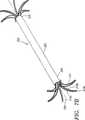
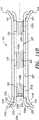
図に示すように、複数のスプライン210が、筒状シャフト202の近位端204、および好ましくは、近位端と遠位端204、206の両方から延在している。スプライン210は、軸方向にほぼ閉じた状態(図4Aおよび5Aに示す)と横方向にほぼ開いた状態(図4B及び図5Bに示す)間で拡開可能である。スプライン210は、図に示すようなほぼフラットな帯状部材か、丸ワイヤ、フィラメント、あるいは、閉じた状態と開いた状態になるものであれば、他の形状でもよい。 As shown, a plurality of
最も好ましい例が図5A及び5Bに見られる。各スプライン210は、筒状シャフト202に連結された第1の端部領域210aと、カラー212に連結された第2の端部領域210bを具えている。スプライン210の端部領域210a、210bは、例えばヒンジ連結(図示せず)などによって、筒状シャフト202とカラー212にそれぞれ連結するようにしても良い。代替として、端部領域210aと210bは、筒状シャフト202及び/又はカラー212と一体的に成形されていても良く、また、必要に応じて、閉じた状態と開いた状態間で移動するべく曲がるように、十分にフレキシブルとしても良い。したがって、例えば、筒状シャフト202、スプライン210,及びカラー212は、当業者には明らかなとおり、スプライン210を形成するべく従来の方法を用いて適当な材質を筒状にした単一のセクションで構成するようにしても良い。 The most preferred example can be seen in FIGS. 5A and 5B. Each
各スプライン210は、また、中間領域あるいはループ210cを具える。これは、縦軸208に対して実質的に外側に向けて横方向に誘導され、開いた状態を規定する。図5Aに最も良く示されているように、閉じた状態においては、スプライン210の第1及び第2の端部領域210a、210bは互いに近接して位置しており、縦軸208にほぼ平行に延在している。カラー212は、カラー212が閉じた状態のスプライン210内に収まるように、好ましくは筒状シャフト202の直径より実質的に小さな直径を有するようにしてもよい。従って、中間領域210cは、閉じた状態の筒状シャフト202の断面とほぼ同一の広がりを有する。 Each
図5Bに最も良く示されているように、開いた状態においては、カラー212は軸方向において、すなわち筒状シャフト202から離れる方向にずれて位置する。この動きが、第2の端部領域210bを移動させ、これによって、スプライン210の中間領域210cを外側に向けてほぼ横方向に移動させる。従って、開いた状態では、スプライン210が筒状シャフト202の直径より実質的に大きな直径を規定する。 As best shown in FIG. 5B, in the open state, the
図6Aおよび6Bに示す代替の実施形態においては、スプライン210’が第1及び第2の端部領域210a’、210b’、および中間領域210c’を具えており、閉じた状態において実質的にリニアに配置されている(図6A)。第1の端部領域210a’は筒状シャフト202に連結されており、第2の端部領域210b’は、カラー212に連結されている。カラー212は軸方向において、筒状シャフト202側へずれてゆき、これによって、中間領域210c’を止め付けるとともに、スプラインが開いた状態になるまで(図6B)外側に向けてほぼ横方向に移動させる。スプライン210’は、刻み目を付けた領域、あるいは細くなった領域(図示せず)を含み、ヒンジあるいはスプラインを所定の態様、すなわち、中間領域210c’が外側に向けて実質的に横方向に移動させる態様になるよう、止め付ける他の手段を提供するようにしても良い。 In the alternative embodiment shown in FIGS. 6A and 6B, the
カラー212の動きをコントロールされたものにするため、およびスプライ210の開閉を選択的なものにするために、カラー212をアクチュエータ(図示せず)に接続するようにしても良い。アクチュエータは一般的に、筒状シャフト202内に配置されており、好ましい実施形態においては、アクチュエータが細長い制御部材214(図6B)と、シャフト202内に配置したアクチュエートカラー(図示せず)を具える。制御部材214は、カラー212に連結された外側端部216と、筒状シャフト202内の内側端部(図示せず)を有する硬質ロッドかあるいは筒状部材であってもよい。内側端部はアクチュエータカラー(図示せず)上のネジ領域と協働するネジ領域を有する。アクチュエータカラーは、筒状シャフト202内で回転し、制御部材214は筒状シャフト202内で軸方向に移動し、これによってスプライン210に連結されているカラー212をずらせる。アクチュエータはカラー212を介してスプライン210に連結されており、従って、スプライン210を閉じた状態と開いた状態間で選択的に拡開させる。 The
代替として、アクチュエータをコントロールワイヤ(図示せず)としてもよい。コントロールワイヤはカラー212に連結されており、例えば、筒状シャフト202内で軸方向に引っ張られ、カラー212をずらせる。これに代えて、スプライン210が閉じた状態か、あるいは開いた状態の一方にバイアスをかけるようにしても良い。これは例えば筒状シャフト202内へ挿入したツールを使用してコントロールワイヤを引っ張ることによって実現される。機械式、油圧式、空圧式のアクチュエータ等、当業者に明らかなアクチュエータのその他の変形例を提供するようにしても良い。 Alternatively, the actuator may be a control wire (not shown). The control wire is connected to the
図6Aおよび6Bを参照すると、装置200は、例えば、複雑骨折した、破損大腿骨100の骨髄管118内に配置されている。これに代えて、装置200は、上述したとおり、大腿骨100以外の骨に配置するようにしても良い。まず、装置200は、図6Aに示すように、予め形成されている挿入門脈130から骨髄管118へスプライン210を閉じた状態で挿入する。制御部材214が筒状の場合は、ガイドワイヤあるいは他の細長い素子(図示せず)を骨髄管118内に最初に挿入し、装置200をガイドワイヤに追随させ、すなわち制御素子214の管腔(図示せず)を通して、装置200の位置決めをする。 With reference to FIGS. 6A and 6B, the
一旦、装置200が完全に骨髄管118内に挿入されたら、(使用している場合は)ガイドワイヤをはずし、ツール(図示せず)を挿入門脈130から筒状シャフト202内へ導入し、デバイス内でアクチュエータを係合させて駆動する。例えば、ツールはアクチュエートカラーに係合する回転ヘッドを有するドライブツールでもよい。このドライブツールは、手動で、空圧で、及び/または電気的駆動によって、アクチュエートカラーを回転させ、制御部材214を筒状シャフト202内で軸方向に移動させ、次いで、スプライン210が近位端204で拡開するまでカラー212を移動させる。拡開したスプライン210は、近位骨幹端領域120に適合するのに十分にフレキシブルであるか、及び/又は、回復力がある。従って、スプライン210は、近位骨幹端領域120の壁に複数の接触点においてしっかりと係合する。このことは、装置200、ひいては破損した骨のセグメントを軸方向に及び/又はねじれ方向に互いに確実に固定させる。 Once the
好ましくは、近位端204においてスプライン210が開くときに、遠位端206において、スプライン210が同時に開くようにする。代替として、遠位端206においてスプライン210が、たとえば、近位端204に関して述べたと同様のツールと方法を用いて、別のアクチュエータによって独立して開くようにしても良い。更なる代替として、骨髄内装置が、図10A乃至11Bに示す実施例と同様に、単一セットのスプラインのみを有するものとしても良い。 Preferably, when the
更なる代替として、所望であれば、近位側のスプライン210のセットに隣接するカラー212が、スプライン210から更に近位側に延在しており、そこに1または2以上の孔(図示せず)を設けるようにしても良い。装置200の安定性をより確かなものにするために、スクリュ、釘、又は他の連結装置(図示せず)を骨とこれらの孔を通して横方向に挿入することができる。同様に、近位側カラー212の延在部に加えて、あるいはそれに代えて、スプライン210の遠位端セット近傍のカラー212がスプライン210から遠位側に延在しており、他の連結装置を受ける1または2以上の孔を設けるようにしても良い。 As a further alternative, if desired, a
骨折が治癒した後、装置200は挿入門脈130を通じて取り除くようにしても良い。挿入門脈130は、新たに成長した骨(図示せず)によって覆われており、小さな皮膚の切り口から露出する。更に、装置200は近位端204から延在する表示素子(図示せず)を具えていても良い。この場合、表示素子は、新たに成長した骨の表面から露出していても良いし、あるいは表面に埋まっていてもよい。この新たに成長した骨は、表示素子の周辺において除去され、挿入門脈130を露出させる。一旦配設されると、装置200は、アクチュエートカラーを、スプライン素子210を開く時に使用した方向と反対方向に回転させることによってスプライン素子210を閉じる。装置200は、次いで骨髄管118と挿入門脈130から取り外され、上にかぶさる組織によって回復する。 The
代替として、装置200を完全にあるいは部分的に、生化学的に吸収可能な材質で形成し、装置200を取り外す2度目の手術を不要とするか、あるいは装置200の一部のみを除去すれば良いようにしても良い。 Alternatively, if the
図7及び図8を参照すると、第2実施形態に係る骨髄内装置300が示されており、この装置は筒状シャフト302と、縦軸308を規定する近位端および遠位端304、306を具える。筒状シャフト302は、一般的な筒状ボディであり、例えば上述の装置200の筒状シャフト210と同様に、円形もしくは他の形状の断面を有する。 Referring to FIGS. 7 and 8, an
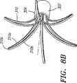
複数のスプライン310は、近位端304から延在しており、好ましくは、図に示すように、筒状シャフト302の近位端および遠位端304、306の双方から延在している。スプライン310はほぼ軸方向に閉じた状態(図7A、図8A)とほぼ横方向に開いた状態(図7B、図8B)の間で拡開可能である。スプライン310は実質的に平らな帯状部材、フィラメント、もしくは開閉状態を呈する他の構成とすることができる。 The plurality of
図7A及び7Bに最も良く示されているように、各々のスプライン310は、筒状シャフト302に連結された第1の端部領域310aと、スプライン310の第1の端部領域310aに入る第2の端部領域310bを具える。スプライン310の第1の端部領域310aは、筒状シャフト302に、例えばヒンジジョイント(図示せず)などで、連結されているか、あるいは代替的に、上述した実施形態と同様に、筒状シャフト302と一体的に形成するようにしても良い。 As best shown in FIGS. 7A and 7B, each
各スプライン310は、中間領域あるいはループ310cを具えており、これは、縦軸308に対して外側に向けてほぼ横方向に方向付けられて、拡開状態を規定する。閉じた状態においては、図8Aに示すように、スプライン310の第1及び第2の端部領域310a、310bは通常互いに近接して配置されており、例えば、中間領域310cが筒状シャフト302の断面とほぼ同じ広がりをもつように、縦軸308にほぼ平行に延在している。図8Bに示すように、開いた状態においては、スプライン310の中間領域310cが外側に向けてほぼ横方向に配置されている。従って、開いた状態では、スプライン310は筒状シャフト302の直径より実質的に大きい直径を規定する。 Each
スプライン310の開閉を制御されたものにするために、アクチュエータ(図示せず)が通常筒状シャフト302内に配置されている。好ましい実施形態においては、アクチュエータは前記第2の端部領域310bが連結されている筒状シャフト302内にて摺動可能なカラー(図示せず)を具えていても良い。このカラーは、例えば上述したネジを設けたカラー及び/又はロッドの構成を用いて、筒状シャフト302内に軸方向に制御可能に配置するようにしても良い。従って、アクチュエータをスプライン310bに連結して、スプライン310を閉じた状態と開いた状態の間で選択的に拡開させるようにする。 In order to control the opening and closing of the
一実施形態では、スプライン310は、開いた状態にするためにバイアスをかけるようにしても良く、カラーは、例えばスプライン310から離れて軸方向にずれて、第2の端部領域310bを引っ張って、スプライン310が閉じた状態になるようにする。カラーは、例えばスプライン310に向けて、反対方向に軸方向に移動した時、スプライン310がフリーになって、開いた状態となる。 In one embodiment, the
使用に際しては、装置300は、上述した実施形態と同様に、破損した骨(図示せず)の骨髄管内に配置される。装置300は予め形成されている挿入門脈を介して、スプライン310を閉じた状態で骨髄管内に挿入される。一旦装置300が完全に骨髄管内に挿入されたら、ツール(図示せず)を挿入門脈を介して筒状シャフト302内に差込んで、装置300内のアクチュエータに係合させ、これを駆動する。すなわち、近位端304のスプライン310を開いて、拡開状態にする。開いたスプライン310は十分にフレキシブル及び/又は回復性があり、近位骨幹端領域に適合させ、及び/又は、近位骨端幹領域の壁に複数の接触点にてしっかり係合するようにする。 In use, the
一実施形態では、遠位端306においてスプライン310は、近位端304にてスプライン310が開く時に同時に開くようにしても良い。代替として、遠位端306におけるスプライン310が、例えば近位端304に対して述べたと同様のツールおよび方法を用いて、別のアクチュエータによって独立して開くようにしても良い。更なる代替として、図10A乃至11Bに示す実施形態と同様に、単一セットのスプラインを具える骨髄内装置を提供するようにしてもおい。 In one embodiment, the
骨折が治癒した後は、上述した実施形態同様に、装置300を取り外すことができる。この取り外しに当たって、通常ツールを筒状シャフト302内に挿入して、アクチュエータに係合させ、スプライン310を開くときの方法と同様にして、スプライン310を閉じる。更なる代替として、上述した実施形態と同様に、装置300が装置300の取り外しのための表示素子(図示せず)を具えているか、及び/又は装置300が少なくとも部分的に生物学的に吸収可能な材料で構成されていても良い。 After the fracture has healed, the
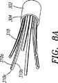
図9A及び9Bを参照すると、他の実施形態に係る骨髄内装置400が示されている。この装置は、上述した実施形態同様に、筒状シャフト402と、縦軸408を規定する近位及び遠位端部404、406を具える。複数のスプライン410は、筒状シャフト402の近位端404から、好ましくは、図に示すように、近位端404及び遠位端406の双方から延在している。スプライン410はほぼ軸方向に閉じた状態(図示せず)と実質的に横方向に拡がった状態(図9B)間で拡開可能である。スプライン410は、筒状シャフト402に連結された第1の端部410aを有する実質的に平らな帯状部材、フィラメントあるいは他の構造と、ルーズな端部410bを具える。好ましくは、スプライン410は拡開状態を仮定するためにバイアスがかけられており、閉じた状態では上に横たわるスリーブ412によって抑制されるようにしても良い。スリーブ412は、上述した摺動可能なカラーと同様に作用する。 Referring to FIGS. 9A and 9B, an
使用に際しては、例えば複雑骨折128を有する損傷した大腿骨100の骨髄管118内に配置される。代替として、デバイス400は、上述した実施形態同様に、大腿骨100以外の骨に配置するようにしても良い。装置400は、図9Aに示すように、予め形成されている挿入門脈130を介して骨髄管118内にスプライン410を閉じた状態で挿入する。装置400が一旦骨髄管118に完全に挿入されたら、スリーブ412が軸方向に誘導されて、スプライン410を露出させて解放する。好ましくは、スプライン410は開状態に向けて自動的に拡開し、また、十分にフレキシブル及び/又は回復性があり、近位骨幹端領域120に適合させるか、及び/又は、近位骨幹端領域120の壁にしっかり係合させる。 In use, for example, it is placed in the
骨折が治癒した後は、装置400は、上述の実施形態と同様に取り外しても良い。この取り外しに際しては、スリーブ412に向けて挿入され、スプライン410を開いたときと同じ方法でスプライン410を元に戻す。更なる代替として、装置400は、装置400の取り外しを容易にする表示素子(図示せず)を具えていても良い。 After the fracture has healed, the
ここに述べるどの装置も少なくとも部分的に、生物科学的に吸収可能な材料、ニチノール(Nitinol)等の形状記憶合金もしくはポリマー、または、ステンレススチール、チタニウム合金等の快復力のある材質で構成するようにしても良い。また、図10A乃至11Bに示す実施形態と同様に、骨髄内装置は、大腿骨、頸骨、寛骨等の骨の首部あるいは他端内のまたはそれに近接する骨の損傷を安定化するために使用される単一セットのスプラインを具えるものであっても良い。 Any device described herein should be constructed at least in part from a bioscientific material, a shape memory alloy or polymer such as Nitinol, or a resilient material such as stainless steel or titanium alloy. Anyway. Also, similar to the embodiment shown in FIGS. 10A-11B, the intramedullary device is used to stabilize bone damage in or near the neck or other end of the bone, such as the femur, tibia, and hipbone. Or a single set of splines.
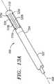
図12乃至図14Bは、本発明の更なる好適な実施形態に係る骨髄内装置500を示すものである。一般的に、装置500は筒状シャフト502と、1又は2以上のカラー512と、細長い制御部材522とを具えている。筒状シャフト502は、縦軸508を規定する近位端及び遠位端504、506を具える。筒状シャフト502は、一般的に、例えば円形あるいは他の形状の断面(例えば楕円形、角形、波形、他)を有する筒状ボディであり、近位端及び遠位端504、506間に延在する管腔507を規定する。筒状ボディ502はソリッドな壁、または、例えば、液体を流通可能にするため、軽量化のため、所望のフレキシビリティを提供するため、及び/又は筒状シャフト502を膨張可能とするために、ラティス、あるいは孔パターンを形成したもので構成しても良い。代替の実施形態においては、筒状シャフト502は、本明細書で従来技術として挙げている米国特許出願第09/426,563号に記載されているような、メッシュで内部連結されている複数の軸方向にねじれた素子、もしくは他の内部連結構造を具えていても良い。 12-14B show an
複数のスプライン510が、図に示すように、筒状シャフト502の近位端504から、好ましくは近位端と遠位端504、506の双方から延在している。複数の支持アーム520がスプライン510に連結されており、スプライン510は軸方向にほぼ閉じた状態(図13A,14A)と、ほぼ横方向に開いた状態(図13B、14B)間で拡開する。好ましくは、スプライン510と支持アーム520は、以下の説明するように単一バンド部材で形成されている。代替として、これらは、例えば、溶接、ボンディング、接着、他によって互いにまとめられた別部材で形成するようにしても良い。更なる代替例では、スプライン510及び/又は支持アーム520は、実質的に丸いワイヤ、フィラメント、あるいは開閉状態を可能にする他の構造であってもよい。 A plurality of
図13Aないし14Bに示されているとおり、各スプライン510は、筒状シャフト502に連結された第1の端部領域510aと、筒状シャフト502から離れた位置にある第2の自由端領域510cを具える。好ましくは、第2の端部領域510cは、閉じた状態において筒状シャフト502から離れて実質的に軸方向に配置されている。各支持アーム520は、カラー512に連結された第1の端部520aと、各スプライン510に連結された第2の端部520cを具える。代替的に、支持アーム520の第2の端部は、スプライン510の中間領域510bに連結されていても良いが、好ましくは、支持アーム520の第2の端部520cは、スプライン510の自由端領域510cに連結されている。 As shown in FIGS. 13A-14B, each
好ましくは、スプライン510の第1の端部領域510aは、筒状シャフト502と一体的に形成されており、一方、支持アーム520の第2の端部520cは各スプライン510の第2の端部領域510aに一体的に形成されている。スプライン510と支持アーム520の中間領域510b、520bは、十分にフレキシブルなものとして、後述する通り、必要に応じて閉じた状態と開いた状態の間で移動するべく曲がるようになっている。例えば、筒状シャフト502、スプライン510および支持アーム520は、後述するとおり、適宜材料を除去して筒状とした単一のセクションから構成するようにしても良い。代替として、スプライン510の第1端部領域510aは、溶接ジョイント、ヒンジ、ピン(図示せず)によって筒状シャフト502に接続されている別々のバンドであってもよく、及び/または、支持アーム520の第2の端部520cは、スプライン510の第2の端部領域510cに溶接ジョイント、ヒンジまたはピン(図示せず)によって連結されていても良い。 Preferably, the first end region 510 a of the
図14A及び14Bを参照すると、制御部材522は、近位端及び遠位端524、526を有するソリッドロッドあるいは筒状部材であってもよい。制御部材522は、筒状シャフト502の管腔507内に制御部材を受け入れられるような径、あるいは他の断面を有する。好ましくは、図に示すように、制御部材522は、近位ネジ領域528a、中間ねじ領域528b、および遠位ネジ領域528cなどの、1又は2以上のネジ領域を具える。より好ましくは、後述するとおり、近位ネジ領域及び遠位ネジ領域528a、528cが互いに対向するねじを有する。 Referring to FIGS. 14A and 14B, the
筒状部材502は、ロッド522の中間ネジ領域528bと同じようにネジが切られている、内側表面532を規定する管腔507内に位置する内部環状領域530を具えている。環状領域530は、好ましくは制御部材522と同様の径を有し、内側表面532のネジが中間ネジ領域528bに係合して、ロッド522が軸508を中心に回転する場合以外は、ロッドが軸方向に移動しないようにする。環状領域530は、筒状シャフト592を機械的に削って製造することができる、あるいは、管腔507内に挿入され、中間位置に、溶接、ボンディング、他によって固定された環状スリーブであってもよい。
同様に、カラー512もネジを切った内側表面を有しており、これは制御部材522の近位ネジ領域及び遠位ネジ領域528a、528cに螺合する。好ましくは、近位カラー512aは、遠位カラー512bに対向する内側にネジを切ったパターンを有しており、それぞれ、近位ネジ領域及び遠位ネジ領域528a、528cに螺合する。更に、カラー512はカラー512が筒状シャフト502の近位端および遠位端504、506内の管腔507内に摺動可能に受け入れられるような外径を有する。カラー512は、後述するように、支持アーム520の第1の端部520aを受けるスロットあるいはポケット(図示せず)を具えていても良い。 Similarly, the
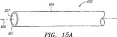
図15Aないし15Dを参照すると、筒状シャフト502と一体的な要素としてのスプライン510及び支持アーム520の好ましい製造方法が示されている。一方の端部のみしか記載されていないが、スプライン510および支持アーム520は、所望の場合は、両端に形成される。更に、筒状シャフト502を製造する順次のステップは重要ではなくどのような順で完成するようにしても良い。 Referring to FIGS. 15A-15D, a preferred method of manufacturing the
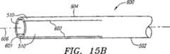
まず、図15Aに示すように、好ましくは中空(あるいは他の)形状を有する細長いチューブ600を用意し、最終製品としての筒状シャフト502と、筒状シャフト502の一端(もしくは両端)のスプライン510を合わせた長さに対応する長さにカットする。このチューブには十分に保全性のある様々なバイオコンパチブル材料を使用することができる。好ましくは、ステンレススチールあるいはチタニウムが用いられる。チューブ600の端部604に、縦方向に軸606とほぼ平行に延在する第1のスロット602を形成し、これによって、図15Bに示すように、近接するスロット602間でスプライン510を規定する。第1のスロット602は、レーザ切断、機械的切断、他によって形成することができる。所望であれば、第1スロット602で規定される縦方向のエッジは、丸くしたり、面取りしたり、あるいは、近接するスプライン510を、例えば閉じた状態から、あるいは閉じた状態に方向付ける時に、互いにつかみ合わないようにするべく、変形させることができる。 First, as shown in FIG. 15A, an
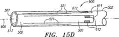
図15Cを参照すると、一対の第2のスロット608が近接する第1のスロット間に設けられている。これは、チューブ600の端部601に全体的に延在することなく軸606にほぼ平行に延在している。第2のスロット608の端部は、周辺スロット610に連結されており、これによって支持アーム520を規定している。従って、各スプライン520は、一対の狭いステム511によって規定され、各支持部材520の各々の側において、筒状シャフト502から自由端510cまで延在する。支持アーム520は、図に示すように、スプライン510より長くして、スプライン510に比してより大きなフレキシビリティを与えるようにしても良い。また、代替として、支持アーム520はスプライン510と同じ長さか、あるいはスプライン510より短くても良い。当業者は、スプライン510と、支持アーム520に関連する幅及び長さを容易に決定して、所望の延在を提供し、開閉を容易にすることができる。 Referring to FIG. 15C, a pair of
さらに、図15Dに示すように、スプライン510の自由端510cは、ギザギザの歯513などの細胞に係合する要素を加えるようにしても良い。代替として、あるいはこれに加えて、自由端510cは、例えば、半径方向に外側に向けて(図示せず)曲げられるか、カーブしており、インプラントされている間、骨と他の細胞の係合をより確実なものとするようにしても良い。更に、各支持アーム520の第1の端部520aに1または2以上のノッチ612を形成して、支持アーム520をカラー512に固定するタブ614を規定するようにしても良い。更なる変形例においては、スプライン510と、支持アーム520を例えば、溶接、摩擦フィット、係合ネジ、ボンディング、その他によって、筒状シャフト(図示せず)の一端あるいは両端に取り付けた別の筒状スリーブに形成するようにしても良い。 Further, as shown in FIG. 15D, the
図14A及び14Bを参照すると、一端スプライン510と支持アーム520が一旦形成されるか、あるいは、筒状シャフト502の一端または両端504、506に取り付けられたら、カラー512を管腔507内へ挿入し、支持アーム520の第1の端部520aを各カラー512に取り付けることができる。カラー512は、各支持アーム520のタブ614を受けるスロットまたは溝(図示せず)を具えていても良い。これに加えて、あるいは代替として、支持アーム520の第1の端部520aをカラー512に張り付けるかあるいは溶接するようにしても良い。 14A and 14B, once the
好ましくは、カラー512は、制御部材522の上に筒状シャフト502の中へねじ込むようにしても良い。制御部材522は、筒状シャフト502の管腔内に挿入され、環状領域530を介して近位及び遠位端524、526が、筒状シャフト502の近位端及び遠位端504、506内に位置するまでねじ込まれる。カラー512は、カラー512が管腔507に入って、支持アーム520の第1の端部520a近傍に位置するまで、近位端524(及び/又は遠位端526)にネジ入れる。支持アーム520は、上述の通り、このようにして、カラー512に取り付ける。 Preferably, the
最初に、図13Aに示すように、スプライン510が閉じた状態になるようにして装置500を提供する。閉状態では、スプライン510と支持アーム520は互いに近接して配置され、これらは縦軸508にほぼ並行に延在する。スプライン510を開くには、ツール(図示せず)を使用して制御部材522を所定の方向に回転させる。例えば、図14A及び14Bに示すように、スロット534か、あるいは、制御部材522から延在するラグ(図示せず)などの、鍵となる要素を提供して、ツールに係合させる。近位ネジ領域及び遠位ネジ領域528a、528cに設けられているネジパターンは、互いに逆手であるので、制御部材522が回転する際に、両カラー512が管腔507から外側に向けて移動する。別に述べるように、近位カラー512aが近位に移動し、遠位カラー512bが遠位に移動する。 Initially, as shown in FIG. 13A, the
このカラー512の動きによって、支持アーム520の第1の端部520aが、外側に向けて軸方向に移動する。(すなわち、近位端504上の支持アーム520に対して近位になるように。)従って、スプライン510が筒状シャフト502の近位端及び遠位端504、506の両方にあれば、近位及び遠位の支持アーム520の第1の端部520aが互いに離れる方向に移動する。支持アーム520の第2の端部520cは、スプライン510に連結されているので、支持アーム520の中間領域520bを止め付けて、スプライン510を、図12に示すように、スプラインが縦軸508に対してほぼ横方向に方向付けられて、拡開状態を規定するまで、スプライン510を外側に向けて半径方向に誘導される。 By the movement of the
骨折の処置用に骨の中で装置500を使用する場合は、上述の実施形態と同様に行う。装置500は、図13Aに示すように、予め形成されている挿入門脈を介して、大腿骨(図示せず)などの骨髄管内にスプライン510を閉じた状態で挿入される。好ましくは、既存の方法を用いてガイドワイヤか、あるいは他の要素(図示せず)を最初に挿入門脈を介して骨の骨髄間に導入し、骨の遠位セグメントまで延在させる。次いで、例えば、ガイドワイヤを管腔を介して制御部材522内に挿入するなどして、装置500をガイドワイヤを越して骨髄管内に進める。装置500を挿入した後は、ガイドワイヤは取り外すことができる。 When the
装置500が骨髄管内に完全に挿入されると、図13Bに示すように、制御部材522が回転してスプライン510が膨らみ、開状態になる。好ましくは、スプライン510は、内部の骨又は他の細胞に実質的に係合するように拡開され、これによって、装置500が骨に対して実質的に埋め込まれることになる。従って、装置500は、装置500がインプラントされている骨のセグメントが軸方向に動いたり、曲がったり、及び/または他に対して回転したりすることを防止することになる。更に、より一層の安定性が要求される場合は、近位端504上のスプライン510を越えて近位側に延在する近位側の延長部(図示せず)を設けるようにしてもよい。例えば、筒状シャフト502は、スプライン510(延長部を受け入れるためにスプライン510の1または2以上を取るようにしても良い)を越えて近位側に延在する軸方向の延長部(図示せず)を具えるようにしても良く、また、代替として、制御部材522がスプライン510を越えて近位側に延在するようにしても良い。近位延長部を貫通する複数の孔を設けるようにしても良く、スクリュ、釘その他の固定装置をこの孔に、例えば、骨と近位延長部を横切ように、挿入して、骨のセグメントを更に強く固定するようにしても良い。 When the
制御部材522をネジ止めすることの利点は、装置500の一方の端部のスプライン510が、他端のスプライン510より大きく拡開することができる点である。制御部材522を単に回転させて各スプラインのセットを他方のスプラインとほぼ同じように拡開させるよりは、制御部材522に軸方向に力を加えて筒状シャフト502を通って制御部材522を軸方向に移動させるようにした方がよい。従って、筒状シャフト502に対してカラー512が移動するより、むしろ一のカラー512が実質的に静止しており、他のカラー512がより外側に移動する方がよい。 An advantage of screwing the
損傷が治癒した後は、上述した実施形態と同様に、装置500を取り外すことができる。この取り外しに際しては、スプライン510を拡開する方法と同様に、ツールを挿入してスプライン510を閉じた状態に戻すことができる。更なる代替として、装置500が装置500の位置決め及び/又は取り外しを容易にする表示要素(図示せず)を具えていても良い。 After the injury has healed, the
図16を参照すると、代替の実施形態に係る骨髄内装置700が示されており、上述した実施形態と同様に、これは筒状シャフト702の一方の端部に設けた第一のスプラインセット710を具える。更に、装置700は筒状シャフト702の端部704と706の間の中間位置に位置する第2のスプラインセット740を具える。第2のスプラインセット740は、支持アーム750を具え、これらのアームは、端部704に形成されているスプラインセットと同様に、筒状シャフト702の壁に直接形成することができる。カラー(図示せず)が、上述の実施形態と同様に、例えばネジが切られているロッドや、他の制御部材(図示せず)などの筒状シャフト702内に挿入され、該カラーが第2のスプラインセット740の近位に位置する。支持アーム750は、上述の実施形態と同様に、カラーに連結され、ロッドの回転によってカラーを軸方向に移動させて、第2のスプラインセット740を拡開させる。更に、複数の孔(図示せず)を筒状シャフト702を通るように設けても良い。上述の実施形態と同様に、スクリュ、釘または他の固定装置をこのホールを介して例えば骨とシャフトを通って横切るように挿入し、骨のセグメントをより一層強く固定するようにしても良い。 Referring to FIG. 16, an
1セットの中間スプライン740のみが示されているが、スプラインのセットを筒状シャフトに沿って同様にいくつ設けるようにしても良い。従って、装置700は長骨内にインプラントされる場合、装置700が拡開して、骨の長さに沿って骨の数カ所に係合する。更に、第1及び第2のスプラインセット710、740はほぼ同じ長さを有するように記載されているが、スプラインの長さが異なるようにしてもよい。例えば、中間部のスプラインセットを、骨の狭い領域内で拡開するように端部のスプラインセットより短くして、端部のスプラインセットが骨の端部のような大きくなった領域内で拡開するようにしてもよい。 Although only one set of
更なる代替として、本発明に係る装置は、骨髄内1次固定ステムプロテーゼセクションのベースとして用いるようにしても良い。例えば、アダプタ(図示せず)を装置に取り付けて、例えば筒状シャフトの近位または遠位にスプラインセットを設け、丸形部材、ソケット、あるいは他のジョイント要素(図示せず)などの、プロテーゼ人工関節表面をこれに取り付けるようにしても良い。代替として、プロテーゼをスプラインセットに直接固定するようにしても良い。従って、装置は単に破損した骨を安定させるのに加えて、あるいはこれに買えて、関節交換プロセスに使用することもできる。 As a further alternative, the device according to the invention may be used as a base for an intramedullary primary fixation stem prosthesis section. For example, an adapter (not shown) can be attached to the device to provide a spline set, for example proximal or distal to the cylindrical shaft, and a prosthesis such as a round member, socket, or other joint element (not shown) An artificial joint surface may be attached thereto. Alternatively, the prosthesis may be secured directly to the spline set. Thus, the device can be used in the joint replacement process in addition to or in addition to stabilizing broken bone.
好ましい方法、および実施形態を図面に示し、説明したが、当業者であれば本発明の範囲から逸脱することなく、様々な変形をすることが可能である。従って、本発明は、以下に述べる請求項の記載されている限り、これらの実施形態に限定されるものではない。 While the preferred method and embodiments have been illustrated and described in the drawings, various modifications can be made by those skilled in the art without departing from the scope of the invention. Accordingly, the invention is not limited to these embodiments as long as the following claims are described.
Claims (29)
Translated fromJapanese第1及び第2の端部領域を有し、両端部間の縦軸を規定する細長いボディと;
前記第1の領域から延在する複数のスプラインであって、当該スプラインが前記第1の端部領域に連結した第1の端部と前記第1の端部領域から離れて位置する第2の端部とを具え、当該スプラインの第2の端部が一般的に軸方向に閉じた状態から実質的に横方向に開いた状態へ誘導されることが可能であり、更に、各スプラインが閉じた状態において、第1の縦方向のセグメント及び第2の縦方向のセグメントを具えているスプラインと、
前記スプラインに連結された複数の支持アームであって、各支持アームが各スプラインの第1の縦方向のセグメントと第2の縦方向のセグメントとの間に配置された支持アームと、
前記支持アームに連結されたアクチュエータであって、前記細長いボディに対して軸方向に移動可能であり、前記支持アームに前記スプラインの第2の端部を閉じた状態から開いた状態に誘導させるアクチュエータと、
を具えることを特徴とする装置。In a device that stabilizes bones,
An elongate body having first and second end regions and defining a longitudinal axis between the ends;
A plurality of splines extending from the first region, wherein the splines are located away from the first end region and a first end connected to the first end region; comprising an end portion, a second end portion of the spline is generally derived from closed axially into substantially opened laterallyare possible Rukoto further spline is closed A splinecomprising a first longitudinal segment and a second longitudinal segment ,
A plurality of support arms coupled to the splines, each support arm being disposed between a first longitudinal segment and a second longitudinal segment of each spline;
An actuator coupled to the support arm, wherein the actuator is movable in an axial direction with respect to the elongated body, and causes the support arm to guide the second end of the spline from a closed state to an open state. When,
A device characterized by comprising.
第1及び第2の端部領域を有し、両端部間の縦軸を規定する細長いボディと、An elongated body having first and second end regions and defining a longitudinal axis between the ends,
前記第1の端部領域から延在する複数のスプラインであって、当該スプラインが前記第1の端部領域に連結した第1の端部と前記第1の端部領域から離れて位置する第2の端部とを具え、当該スプラインの第2の端部が一般的に軸方向に閉じた状態から実質的に横方向に開いた状態へ誘導され得るスプラインと、A plurality of splines extending from the first end region, wherein the splines are located apart from the first end region connected to the first end region and the first end region; A spline that can be guided from a generally axially closed state to a substantially laterally open state, wherein the second end of the spline is generally axially closed;
前記スプラインに連結された複数の支持アームと、A plurality of support arms connected to the spline;
前記支持アームに連結されたアクチュエータであって、前記細長いボディに対して軸方向に移動可能であり、前記支持アームに前記スプラインの第2の端部を閉じた状態から開いた状態に誘導させるアクチュエータと、を具えており、An actuator coupled to the support arm, wherein the actuator is movable in an axial direction with respect to the elongated body, and causes the support arm to guide the second end of the spline from a closed state to an open state. And,
前記支持アームが前記スプラインの中間部に連結されていることを特徴とする装置。The apparatus is characterized in that the support arm is connected to an intermediate portion of the spline.
第1及び第2の端部領域を有し、両端部間の縦軸を規定する細長いボディと、
前記第1の端部領域から延在する複数のスプラインであって、当該スプラインが前記第1の端部領域に連結した第1の端部と前記第1の端部領域から離れて位置する第2の端部とを具え、当該スプラインの第2の端部が一般的に軸方向に閉じた状態から実質的に横方向に開いた状態へ誘導され得るスプラインと、
前記スプラインに連結された複数の支持アームと、
前記支持アームに連結されたアクチュエータであって、前記細長いボディに対して軸方向に移動可能であり、前記支持アームに前記スプラインの第2の端部を閉じた状態から開いた状態に誘導させるアクチュエータと、を具えており、
前記細長ボディが筒状部材を具え、前記スプラインが前記筒状部材の第1の端部領域内の縦型スロットをカットすることによって形成されることを特徴とする装置。In a device that stabilizes bones,
An elongated body having first and second end regions and defining a longitudinal axis between the ends,
A plurality of splines extending from the first end region, wherein the splines are located apart from the first end region connected to the first end region and the first end region; A spline that can be guided from a generally axially closed state to a substantially laterally open state, wherein the second end of the spline is generally axially closed;
A plurality of support arms connected to the spline;
An actuator coupled to the support arm, the actuator being axially movable with respect to the elongated body, and causing the support arm to guide the second end of the spline from a closed state to an open state And,
The apparatus wherein the elongate body comprises a tubular member and the spline is formed by cutting a vertical slot in a first end region of the tubular member.
第1及び第2の端部領域を有し、両端部間の縦軸を規定する細長いボディと、
前記第1の端部領域から延在する複数のスプラインであって、当該スプラインが前記第1の端部領域に連結した第1の端部と前記第1の端部領域から離れて位置する第2の端部とを具え、当該スプラインの第2の端部が一般的に軸方向に閉じた状態から実質的に横方向に開いた状態へ誘導され得るスプラインと、
前記スプラインに連結された複数の支持アームと、
前記支持アームに連結されたアクチュエータであって、前記細長いボディに対して軸方向に移動可能であり、前記支持アームに前記スプラインの第2の端部を閉じた状態から開いた状態に誘導させるアクチュエータと、を具えており、
前記細長ボディが前記第1端部領域と、第2の端部領域間に中間領域を具え、前記複数のスプラインが第1の複数のスプラインを具え、前記複数の支持アームが前記第1の複数のスプラインに連結された第1の複数の支持アームを具え、前記装置が更に、
前記細長ボディの中間領域から延在する第1の複数のスプラインであって、通常の軸方向に閉じた状態から実質的に横方向に開いた状態へ誘導されうるスプラインと、
前記第2の複数のスプラインに連結された第2の複数の支持アームと、
を具え、
前記アクチュエータが前記支持アームに取り付けられており、当該アクチュエータが前記細長ボディに対して軸方向に移動可能であり、前記第1及び第2の複数の支持アームに、前記第1及び第2の複数のスプラインを前記閉じた状態と開いた状態間で誘導させることを特徴とする装置。In a device that stabilizes bones,
An elongated body having first and second end regions and defining a longitudinal axis between the ends,
A plurality of splines extending from the first end region, wherein the splines are located apart from the first end region connected to the first end region and the first end region; A spline that can be guided from a generally axially closed state to a substantially laterally open state, wherein the second end of the spline is generally axially closed;
A plurality of support arms connected to the spline;
An actuator coupled to the support arm, wherein the actuator is movable in an axial direction with respect to the elongated body, and causes the support arm to guide the second end of the spline from a closed state to an open state. And,
The elongated body includes an intermediate region between the first end region and the second end region, the plurality of splines include a first plurality of splines, and the plurality of support arms include the first plurality of splines. A first plurality of support arms coupled to the splines;
A first plurality of splines extending from an intermediate region of the elongate body, the splines being capable of being guided from a normal axially closed state to a substantially laterally open state;
A second plurality of support arms coupled to the second plurality of splines;
With
The actuator is attached to the support arm, the actuator is movable in an axial direction with respect to the elongated body, and the first and second plurality of support arms include the first and second plurality of support arms. The spline is guided between the closed state and the open state.
前記管腔内に入る細長部材と;
前記細長部材と前記第1及び第2の複数の支持アームにそれぞれ連結された第1および第2のカラーと、を具え、
前記細長部材の前記筒状シャフトを中心とする回転が、前記第1及び第2のカラーを軸方向に移動させ、これによって、前記第1及び第2の複数の支持アームに前記スプラインを前記閉じた状態と開いた状態との間で誘導させることを特徴とする装置。18. The apparatus of claim 17, wherein the elongate body comprises a cylindrical shaft having a lumen extending between the proximal end region and the distal end region, the actuator comprising:
An elongate member that enters the lumen;
First and second collars coupled to the elongate member and the first and second plurality of support arms, respectively,
Rotation of the elongate member about the cylindrical shaft causes the first and second collars to move axially, thereby closing the splines on the first and second support arms. A device characterized by being guided between a closed state and an open state.
第1及び第2の端部領域を具え、これらの領域間の縦軸を規定する細長筒状ボディを提供するステップと;
前記第1の端部領域内にスプラインであって、前記筒状ボディの第1の端部領域に取り付けられる部分を残す第1の端部と、前記第1の端部に対して軸方向に位置する第2の端部を有し、前記第2の端部が前記筒状ボディに対して自在に移動可能であるスプラインを形成するステップと;
前記スプラインの中に、前記スプラインに対して自在に移動可能である第1の端部と、前記スプラインの中間部に取り付ける部分を残す第2の端部を有する支持アームを形成するステップと;
前記支持アームの第1の端部を、前記筒状ボディに対して軸方向に移動可能であって、前記スプラインの第2の端部を縦軸に対して外側に向けて横方向に方向づけるアクチュエータに連結するステップと;
を具えることを特徴とする方法。In a method of manufacturing a device for stabilizing bone, the method includes:
Providing an elongated cylindrical body comprising first and second end regions and defining a longitudinal axis between these regions;
A first end that is a spline in the first end region and leaves a portion attached to the first end region of the tubular body; and axially relative to the first end Forming a spline having a second end located, the second end being freely movable relative to the cylindrical body;
Forming a support arm in the spline having a first end that is freely movable relative to the spline and a second end that leaves a portion attached toan intermediate portion of the spline;
An actuator capable of moving the first end of the support arm in an axial direction with respect to the cylindrical body and directing the second end of the spline laterally outward with respect to the vertical axis Connecting to;
A method characterized by comprising.
第1及び第2の端部領域を具え、これらの領域間の縦軸を規定する細長筒状ボディを提供するステップと;
前記第1の端部領域内にスプラインであって、前記筒状ボディの第1の端部領域に取り付けられる部分を残す第1の端部と、前記第1の端部に対して軸方向に位置する第2の端部を有し、前記第2の端部が前記筒状ボディに対して自在に移動可能であるスプラインを形成するステップと;
前記スプラインの中に、前記スプラインに対して自在に移動可能である第1の端部と、前記スプラインの中間部に取り付ける部分を残す第2の端部を有する支持アームを形成するステップと;
前記支持アームの第1の端部を、前記筒状ボディに対して軸方向に移動可能であって、前記スプラインの第2の端部を縦軸に対して外側に向けて横方向に方向づけるアクチュエータに連結するステップと;
を具えており、
前記スプラインを形成するステップが、前記第1の端部領域に縦スロットを形成する工程を具えることを特徴とする方法。In a method of manufacturing a device for stabilizing bone, the method includes:
Providing an elongated cylindrical body comprising first and second end regions and defining a longitudinal axis between these regions;
A first end that is a spline in the first end region and leaves a portion attached to the first end region of the tubular body; and axially relative to the first end Forming a spline having a second end located, the second end being freely movable relative to the cylindrical body;
Forming a support arm in the spline having a first end that is freely movable relative to the spline and a second end that leaves a portion attached to an intermediate portion of the spline;
An actuator capable of moving the first end of the support arm in an axial direction with respect to the cylindrical body and directing the second end of the spline laterally outward with respect to the vertical axis Connecting to;
With
The method of forming the spline comprises forming a longitudinal slot in the first end region.
第1及び第2の端部領域を具え、これらの領域間の縦軸を規定する細長筒状ボディを提供するステップと;
前記第1の端部領域内にスプラインであって、前記筒状ボディの第1の端部領域に取り付けられる部分を残す第1の端部と、前記第1の端部に対して軸方向に位置する第2の端部を有し、前記第2の端部が前記筒状ボディに対して自在に移動可能であるスプラインを形成するステップと;
前記スプラインの中に、前記スプラインに対して自在に移動可能である第1の端部と、前記スプラインの中間部に取り付ける部分を残す第2の端部を有する支持アームを形成するステップと;
前記支持アームの第1の端部を、前記筒状ボディに対して軸方向に移動可能であって、前記スプラインの第2の端部を縦軸に対して外側に向けて横方向に方向づけるアクチュエータに連結するステップと;
を具えており、
前記支持アームを形成するステップが前記各スプラインの部分を部分的にカットするステップを具えることを特徴とする方法。In a method of manufacturing a device for stabilizing bone, the method includes:
Providing an elongated cylindrical body comprising first and second end regions and defining a longitudinal axis between these regions;
A first end that is a spline in the first end region and leaves a portion attached to the first end region of the tubular body; and axially relative to the first end Forming a spline having a second end located, the second end being freely movable relative to the cylindrical body;
Forming a support arm in the spline having a first end that is freely movable relative to the spline and a second end that leaves a portion attached to an intermediate portion of the spline;
An actuator capable of moving the first end of the support arm in an axial direction with respect to the cylindrical body and directing the second end of the spline laterally outward with respect to the vertical axis Connecting to;
With
The method of forming the support arm comprises partially cutting a portion of each spline.
前記細長部材を前記筒状ボディ内の軸方向の管腔内に挿入するステップと、
前記カラーを当該カラーが前記支持アームの第1の端部の近位になるまで前記細長部材にネジ入れるステップと;
前記支持アームの第1の端部を前記第1のカラーへ連結するステップと;
を具えることを特徴とする方法。25. A method according toany one of claims 22to 24 , wherein the actuator comprises an elongate member and a first collar, and the connecting step;
Inserting the elongate member into an axial lumen in the cylindrical body;
Threading the collar into the elongate member until the collar is proximal to the first end of the support arm;
Connecting a first end of the support arm to the first collar;
A method characterized by comprising.
第2のカラーを前記細長部材の上に前記第2のカラーが前記筒状ボディの前記第2の端部領域上で前記支持アームの近位になるまでネジ入れるステップと;
前記第2の端部領域上の前記支持アームを、前記第2のカラーに連結するステップと;
を具えることを特徴とする方法。28. The method of claim 27, further comprising:
Threading a second collar over the elongated member until the second collar is proximal to the support arm on the second end region of the tubular body;
Connecting the support arm on the second end region to the second collar;
A method characterized by comprising.
Applications Claiming Priority (5)
| Application Number | Priority Date | Filing Date | Title |
|---|---|---|---|
| US10559398P | 1998-10-26 | 1998-10-26 | |
| US09/426,563US6261289B1 (en) | 1998-10-26 | 1999-10-22 | Expandable orthopedic device |
| US09/907,514US6554833B2 (en) | 1998-10-26 | 2001-07-16 | Expandable orthopedic device |
| PCT/US2002/022382WO2003007830A1 (en) | 1998-10-26 | 2002-07-11 | Expandable orthopedic device |
| US10/349,210US7052498B2 (en) | 1998-10-26 | 2003-01-21 | Expandable orthopedic device |
Publications (2)
| Publication Number | Publication Date |
|---|---|
| JP2004535249A JP2004535249A (en) | 2004-11-25 |
| JP4262595B2true JP4262595B2 (en) | 2009-05-13 |
Family
ID=36075051
Family Applications (1)
| Application Number | Title | Priority Date | Filing Date |
|---|---|---|---|
| JP2003513442AExpired - Fee RelatedJP4262595B2 (en) | 1998-10-26 | 2002-07-11 | Expandable orthopedic device |
Country Status (9)
| Country | Link |
|---|---|
| US (3) | US7052498B2 (en) |
| EP (1) | EP1406548B1 (en) |
| JP (1) | JP4262595B2 (en) |
| CN (1) | CN100515358C (en) |
| AT (1) | ATE304817T1 (en) |
| CA (1) | CA2452508C (en) |
| DE (1) | DE60206274T2 (en) |
| RU (1) | RU2296526C2 (en) |
| WO (1) | WO2003007830A1 (en) |
Families Citing this family (152)
| Publication number | Priority date | Publication date | Assignee | Title |
|---|---|---|---|---|
| US7959652B2 (en)* | 2005-04-18 | 2011-06-14 | Kyphon Sarl | Interspinous process implant having deployable wings and method of implantation |
| US20070282443A1 (en)* | 1997-03-07 | 2007-12-06 | Disc-O-Tech Medical Technologies Ltd. | Expandable element |
| IL128261A0 (en)* | 1999-01-27 | 1999-11-30 | Disc O Tech Medical Tech Ltd | Expandable element |
| WO2004110300A2 (en)* | 2001-07-25 | 2004-12-23 | Disc Orthopaedic Technologies Inc. | Deformable tools and implants |
| CA2452508C (en) | 1998-10-26 | 2010-09-14 | Expanding Orthopedics Inc. | Expandable orthopedic device |
| US7621950B1 (en) | 1999-01-27 | 2009-11-24 | Kyphon Sarl | Expandable intervertebral spacer |
| WO2004014243A1 (en) | 2002-08-10 | 2004-02-19 | William H Simon | Method and apparatus for repairing the mid-food region via an intermedullary nail |
| WO2004043271A1 (en)* | 2002-11-08 | 2004-05-27 | Sdgi Holdings, Inc. | Transpedicular intervertebral disk access methods and devices |
| US7122043B2 (en) | 2003-05-19 | 2006-10-17 | Stout Medical Group, L.P. | Tissue distention device and related methods for therapeutic intervention |
| NZ545342A (en)* | 2003-08-29 | 2008-11-28 | Synthes Gmbh | Intramedullary nail |
| AU2005206175A1 (en)* | 2004-01-16 | 2005-08-04 | Expanding Orthopedics, Inc. | Bone fracture treatment devices |
| US7632277B2 (en)* | 2004-03-29 | 2009-12-15 | Woll Bioorthopedics Llc | Orthopedic intramedullary fixation system |
| EP1582161A1 (en)* | 2004-03-31 | 2005-10-05 | Orthofix International B.V. | Intramedullary nail provided with expansion fixing means operated by one or more driving elements |
| WO2005094705A2 (en)* | 2004-03-31 | 2005-10-13 | Orthofix S.R.L | Shape memory alloy comprising intramedullary nail provided with expansion fixing means |
| US8162942B2 (en)* | 2004-03-31 | 2012-04-24 | Orthofix S.R.L. | Intramedullary nail comprising elements of shape-memory material |
| EP1582162A1 (en)* | 2004-03-31 | 2005-10-05 | Orthofix International B.V. | Intramedullary nail provided with expansion fixing means comprising at least one element of shape-retention material |
| US7722612B2 (en)* | 2004-05-19 | 2010-05-25 | Sintea Biotech S.P.A. | Devices, kit and method for kyphoplasty |
| DE602005023605D1 (en)* | 2004-05-21 | 2010-10-28 | Myers Surgical Solutions Llc | FRACTURE FIXATION AND STITIZATION STABILIZATION SYSTEM |
| US20100241120A1 (en)* | 2004-10-04 | 2010-09-23 | Saint Louis University | Intramedullary nail device and method for repairing long bone |
| JP4981690B2 (en) | 2005-02-08 | 2012-07-25 | コーニンクレッカ フィリップス エレクトロニクス エヌ ヴィ | System and method for percutaneous lingual plastic surgery |
| US8096303B2 (en) | 2005-02-08 | 2012-01-17 | Koninklijke Philips Electronics N.V | Airway implants and methods and devices for insertion and retrieval |
| US8371307B2 (en) | 2005-02-08 | 2013-02-12 | Koninklijke Philips Electronics N.V. | Methods and devices for the treatment of airway obstruction, sleep apnea and snoring |
| FR2884406B1 (en) | 2005-04-14 | 2008-10-17 | Memometal Technologies Soc Par | INTRAMEDULAR OSTEOSYNTHESIS DEVICE OF TWO BONE PARTS, IN PARTICULAR HAND AND / OR FOOT |
| US20060264951A1 (en) | 2005-05-18 | 2006-11-23 | Nelson Charles L | Minimally Invasive Actuable Bone Fixation Devices Having a Retractable Interdigitation Process |
| US9060820B2 (en) | 2005-05-18 | 2015-06-23 | Sonoma Orthopedic Products, Inc. | Segmented intramedullary fracture fixation devices and methods |
| US8961516B2 (en) | 2005-05-18 | 2015-02-24 | Sonoma Orthopedic Products, Inc. | Straight intramedullary fracture fixation devices and methods |
| US7753938B2 (en)* | 2005-08-05 | 2010-07-13 | Synthes Usa, Llc | Apparatus for treating spinal stenosis |
| US8998923B2 (en)* | 2005-08-31 | 2015-04-07 | Spinealign Medical, Inc. | Threaded bone filling material plunger |
| US20070067034A1 (en)* | 2005-08-31 | 2007-03-22 | Chirico Paul E | Implantable devices and methods for treating micro-architecture deterioration of bone tissue |
| NL1030218C2 (en)* | 2005-10-18 | 2007-04-19 | Gert Dr Ir Nijenbanning | Medical device for treating fractured bones or attaching stabilizing elements to bone parts. |
| US20070213583A1 (en)* | 2006-03-10 | 2007-09-13 | Kim Daniel H | Percutaneous access and visualization of the spine |
| US7806900B2 (en) | 2006-04-26 | 2010-10-05 | Illuminoss Medical, Inc. | Apparatus and methods for delivery of reinforcing materials to bone |
| US7811290B2 (en)* | 2006-04-26 | 2010-10-12 | Illuminoss Medical, Inc. | Apparatus and methods for reinforcing bone |
| US20080294204A1 (en)* | 2007-03-07 | 2008-11-27 | Spineworks Medical, Inc. | Systems, methods, and devices for soft tissue attachment to bone |
| EP1905367A1 (en)* | 2006-09-28 | 2008-04-02 | Orthofix S.r.l. | Intramedullary osteosynthesis device |
| US7857840B2 (en) | 2006-10-02 | 2010-12-28 | The Cleveland Clinic Foundation | Fastener assembly |
| US8449583B2 (en) | 2006-10-02 | 2013-05-28 | The Cleveland Clinic Foundation | Fastener assembly |
| US7879041B2 (en)* | 2006-11-10 | 2011-02-01 | Illuminoss Medical, Inc. | Systems and methods for internal bone fixation |
| CA2669129C (en) | 2006-11-10 | 2014-09-16 | Illuminoss Medical, Inc. | Systems and methods for internal bone fixation |
| FR2908626B1 (en)* | 2006-11-16 | 2010-01-15 | Newdeal | INTER-PHALANGEAL ARTHRODESIS IMPLANT, SURGICAL KIT AND METHOD OF MANUFACTURING THE SAME |
| WO2008064346A2 (en) | 2006-11-22 | 2008-05-29 | Sonoma Orthopedic Products, Inc. | Fracture fixation device, tools and methods |
| GB0624562D0 (en)* | 2006-12-08 | 2007-01-17 | Airbus Uk Ltd | Self Curing Injection Nozzle |
| WO2008109566A1 (en) | 2007-03-02 | 2008-09-12 | Spinealign Medical, Inc. | Fracture fixation system and method |
| WO2008109870A1 (en)* | 2007-03-07 | 2008-09-12 | Spinealign Medical, Inc. | Transdiscal interbody fusion device and method |
| FR2913876B1 (en) | 2007-03-20 | 2009-06-05 | Memometal Technologies Soc Par | OSTEOSYNTHESIS DEVICE |
| AU2008228710A1 (en)* | 2007-03-22 | 2008-09-25 | Novalign Orthopaedics, Inc. | Segmented intramedullary structure |
| WO2008116170A2 (en)* | 2007-03-22 | 2008-09-25 | Novalign Orthopaedics, Inc. | Fracture fixation device with support rods and sheath |
| US20080269745A1 (en)* | 2007-04-24 | 2008-10-30 | Osteolign, Inc. | Thermo-chemically activated intramedullary bone stent |
| WO2008137192A1 (en)* | 2007-05-08 | 2008-11-13 | Spinealign Medical, Inc. | Systems, devices and methods for stabilizing bone |
| US20090276048A1 (en)* | 2007-05-08 | 2009-11-05 | Chirico Paul E | Devices and method for bilateral support of a compression-fractured vertebral body |
| US20100274246A1 (en)* | 2007-05-10 | 2010-10-28 | Oren Globerman | Expandable intramedullary nail for small bone fixation |
| WO2009004603A2 (en) | 2007-07-03 | 2009-01-08 | Sota Orthopaedics Limited | A bolt apparatus |
| EP2178445B1 (en)* | 2007-07-17 | 2012-10-03 | Cook Medical Technologies LLC | Rivet introduction system |
| US9427289B2 (en) | 2007-10-31 | 2016-08-30 | Illuminoss Medical, Inc. | Light source |
| US8740954B2 (en)* | 2007-12-19 | 2014-06-03 | Integral Spine Solutions, Inc. | Device and method for orthopedic fracture fixation |
| US8403968B2 (en) | 2007-12-26 | 2013-03-26 | Illuminoss Medical, Inc. | Apparatus and methods for repairing craniomaxillofacial bones using customized bone plates |
| AU2015203145B2 (en)* | 2008-01-14 | 2017-11-23 | Conventus Orthopaedics Inc. | Apparatus and Methods for Fracture Repair |
| CA2781407A1 (en) | 2008-01-14 | 2009-07-23 | Michael P. Brenzel | Apparatus and methods for fracture repair |
| US20090216260A1 (en)* | 2008-02-20 | 2009-08-27 | Souza Alison M | Interlocking handle |
| EP2293727A1 (en) | 2008-05-28 | 2011-03-16 | Kerflin Orthopedic Innovations, Llc | Fluid-powered elongation instrumentation for correcting orthopedic deformities |
| JP2011523889A (en) | 2008-06-10 | 2011-08-25 | ソノマ・オーソペディック・プロダクツ・インコーポレーテッド | Device, tool and method for fixing fractures |
| US20100168748A1 (en)* | 2008-07-16 | 2010-07-01 | Knopp Peter G | Morselizer |
| KR20110053968A (en)* | 2008-07-23 | 2011-05-24 | 유니버시티 오브 루이빌 리서치 파운데이션, 인코포레이티드 | Hip fracture prevention device and method |
| FR2935601B1 (en) | 2008-09-09 | 2010-10-01 | Memometal Technologies | INTRAMEDULLARY IMPLANT RESORBABLE BETWEEN TWO BONE OR TWO BONE FRAGMENTS |
| JP2012504027A (en)* | 2008-09-26 | 2012-02-16 | ソノマ・オーソペディック・プロダクツ・インコーポレーテッド | Bone fixation device, tool and method |
| WO2010042293A1 (en)* | 2008-10-07 | 2010-04-15 | Synthes Usa, Llc | Expandable bone support |
| WO2010078488A2 (en)* | 2008-12-31 | 2010-07-08 | Spinealign Medical, Inc. | Self-expanding bone stabilization devices |
| US9622798B2 (en)* | 2009-02-17 | 2017-04-18 | Gregory Merrell | Intramedullary compression rod |
| US8012155B2 (en) | 2009-04-02 | 2011-09-06 | Zimmer, Inc. | Apparatus and method for prophylactic hip fixation |
| US8210729B2 (en) | 2009-04-06 | 2012-07-03 | Illuminoss Medical, Inc. | Attachment system for light-conducting fibers |
| US8512338B2 (en) | 2009-04-07 | 2013-08-20 | Illuminoss Medical, Inc. | Photodynamic bone stabilization systems and methods for reinforcing bone |
| US8562550B2 (en)* | 2009-05-27 | 2013-10-22 | Linares Medical Devices, Llc | Interior and exterior cast assemblies for repairing a bone fracture and including interior inflatable or mechanically expandable inserts as well as exterior wrap around and adhesively secured braces |
| KR20120047231A (en)* | 2009-06-17 | 2012-05-11 | 트리니티 올쏘피딕스, 엘엘씨 | Expanding intervertebral device and methods of use |
| EP2467098A4 (en) | 2009-08-19 | 2015-07-08 | Illuminoss Medical Inc | Devices and methods for bone alignment, stabilization and distraction |
| BR112012002215B1 (en) | 2009-09-14 | 2020-06-02 | Synthes Gmbh | HUMAN HEAD FIXATION DEVICE FOR BONES WITH OSTEOPOROSIS. |
| WO2011038315A1 (en) | 2009-09-28 | 2011-03-31 | Zimmer, Inc. | Expandable intramedullary rod |
| US20110178520A1 (en)* | 2010-01-15 | 2011-07-21 | Kyle Taylor | Rotary-rigid orthopaedic rod |
| WO2011091052A1 (en) | 2010-01-20 | 2011-07-28 | Kyle Taylor | Apparatus and methods for bone access and cavity preparation |
| WO2011112615A1 (en) | 2010-03-08 | 2011-09-15 | Krinke Todd A | Apparatus and methods for securing a bone implant |
| US8617160B2 (en) | 2010-03-09 | 2013-12-31 | Torjo Medical Solutions, Inc. | Dynamic intramedullary hardware |
| US9724140B2 (en) | 2010-06-02 | 2017-08-08 | Wright Medical Technology, Inc. | Tapered, cylindrical cruciform hammer toe implant and method |
| US9498273B2 (en) | 2010-06-02 | 2016-11-22 | Wright Medical Technology, Inc. | Orthopedic implant kit |
| US8608785B2 (en) | 2010-06-02 | 2013-12-17 | Wright Medical Technology, Inc. | Hammer toe implant with expansion portion for retrograde approach |
| US8696719B2 (en) | 2010-06-03 | 2014-04-15 | Tarsus Medical Inc. | Methods and devices for treating hallux valgus |
| US8684965B2 (en) | 2010-06-21 | 2014-04-01 | Illuminoss Medical, Inc. | Photodynamic bone stabilization and drug delivery systems |
| WO2012033836A1 (en) | 2010-09-09 | 2012-03-15 | Synthes Usa, Llc | Surgical nail |
| DE102010041226A1 (en)* | 2010-09-22 | 2012-03-22 | Aces Gmbh | Bone anchoring device |
| US8834483B2 (en) | 2010-10-04 | 2014-09-16 | Biomedical Enterprises, Inc. | Method and system for storing and inserting an implant |
| EP2654584A1 (en) | 2010-12-22 | 2013-10-30 | Illuminoss Medical, Inc. | Systems and methods for treating conditions and diseases of the spine |
| US9138219B2 (en) | 2010-12-29 | 2015-09-22 | Tarsus Medical Inc. | Methods and devices for treating a syndesmosis injury |
| EP2471478A1 (en) | 2010-12-31 | 2012-07-04 | ORTHOFIX S.r.l. | Intramedullary nail with shape memory elements for long bones |
| BR112013020956B1 (en)* | 2011-02-14 | 2020-12-08 | Synthes Gmbh | bone fixation set |
| US9028496B2 (en) | 2011-04-12 | 2015-05-12 | William L. Tontz | Device for establishing supportive forces in the bony structure of a skeleton |
| US20130023876A1 (en) | 2011-07-19 | 2013-01-24 | Illuminoss Medical, Inc. | Combination Photodynamic Devices |
| US8936644B2 (en) | 2011-07-19 | 2015-01-20 | Illuminoss Medical, Inc. | Systems and methods for joint stabilization |
| US8652136B2 (en)* | 2011-08-15 | 2014-02-18 | Zimmer, Gmbh | Femoral fracture fixation device |
| US8337495B1 (en) | 2011-08-16 | 2012-12-25 | Powlan Roy Y | Distal locking intramedullary nail |
| AU2012320238B2 (en)* | 2011-10-05 | 2016-09-08 | Smith & Nephew Plc | Medical devices containing shape memory polymer compositions |
| HK1201138A1 (en)* | 2011-10-10 | 2015-08-28 | William Casey Fox | Shape changing bone implant for enhanced healing |
| US8696623B2 (en)* | 2011-11-16 | 2014-04-15 | Mgs Mfg. Group, Inc. | Injection molded adjustable shape abscess irrigation device |
| US9393126B2 (en)* | 2012-04-20 | 2016-07-19 | Peter L. Mayer | Bilaterally placed disc prosthesis for spinal implant and method of bilateral placement |
| US9364339B2 (en)* | 2012-04-30 | 2016-06-14 | Peter L. Mayer | Unilaterally placed expansile spinal prosthesis |
| US8840612B2 (en)* | 2012-05-04 | 2014-09-23 | William L. Tontz | Intraosseous expandable fixation device |
| JP2012196463A (en)* | 2012-05-10 | 2012-10-18 | Saint Louis Univ | Intramedullary nail device and method for mending long bone |
| US9554836B2 (en)* | 2012-06-29 | 2017-01-31 | The Cleveland Clinic Foundation | Intramedullary bone stent |
| US8939977B2 (en) | 2012-07-10 | 2015-01-27 | Illuminoss Medical, Inc. | Systems and methods for separating bone fixation devices from introducer |
| US9681905B2 (en) | 2012-10-02 | 2017-06-20 | Alphatec Spine, Inc. | Expandable screw and methods of use |
| US10271880B2 (en) | 2012-12-05 | 2019-04-30 | Beth Israel Deaconess Medical Center, Inc. | Systems and methods for anisotropy restoring femoroplasty |
| US9687281B2 (en) | 2012-12-20 | 2017-06-27 | Illuminoss Medical, Inc. | Distal tip for bone fixation devices |
| US8945232B2 (en) | 2012-12-31 | 2015-02-03 | Wright Medical Technology, Inc. | Ball and socket implants for correction of hammer toes and claw toes |
| USD720072S1 (en)* | 2013-02-06 | 2014-12-23 | Biomedical Enterprises, Inc. | Orthopedic implant |
| KR102391275B1 (en) | 2013-03-14 | 2022-04-27 | 케이에프엑스 메디컬, 엘엘씨 | Tissue capturing bone anchor |
| CA2904717C (en) | 2013-03-15 | 2021-05-11 | Malcolm Heaven | System and method for securing tissue to bone |
| US9724139B2 (en) | 2013-10-01 | 2017-08-08 | Wright Medical Technology, Inc. | Hammer toe implant and method |
| US9636155B2 (en) | 2013-11-18 | 2017-05-02 | Biomedical Enterprises, Inc. | Method and apparatus for an intramudullary implant and method of implantation thereof |
| US9522022B2 (en) | 2013-11-18 | 2016-12-20 | Biomedical Enterprises, Inc. | Method and appparatus for an intramedullary implant and method of implantation therefor |
| US9474561B2 (en) | 2013-11-19 | 2016-10-25 | Wright Medical Technology, Inc. | Two-wire technique for installing hammertoe implant |
| TWI523634B (en)* | 2013-12-02 | 2016-03-01 | 財團法人金屬工業研究發展中心 | Bone fracture fixation device |
| CN105939677A (en) | 2013-12-12 | 2016-09-14 | 康文图斯整形外科公司 | Tissue displacement tools and methods |
| US9770278B2 (en) | 2014-01-17 | 2017-09-26 | Arthrex, Inc. | Dual tip guide wire |
| US9980715B2 (en) | 2014-02-05 | 2018-05-29 | Trinity Orthopedics, Llc | Anchor devices and methods of use |
| US9498266B2 (en) | 2014-02-12 | 2016-11-22 | Wright Medical Technology, Inc. | Intramedullary implant, system, and method for inserting an implant into a bone |
| US9545274B2 (en) | 2014-02-12 | 2017-01-17 | Wright Medical Technology, Inc. | Intramedullary implant, system, and method for inserting an implant into a bone |
| EP2910209A1 (en)* | 2014-02-21 | 2015-08-26 | NG Patentverwertungs UG | Intramedullary device for osteosynthesis |
| AU2014331633B2 (en) | 2014-09-18 | 2017-06-22 | Wright Medical Technology, Inc | Hammertoe implant and instrument |
| US9814499B2 (en) | 2014-09-30 | 2017-11-14 | Arthrex, Inc. | Intramedullary fracture fixation devices and methods |
| USD745163S1 (en) | 2014-11-13 | 2015-12-08 | Biomedical Enterprises, Inc. | Orthopedic implant |
| USD756513S1 (en) | 2014-11-13 | 2016-05-17 | Biomedical Enterprises, Inc. | Orthopedic implant insertion device |
| USD760894S1 (en) | 2014-11-13 | 2016-07-05 | Biomedical Enterprises, Inc. | Orthopedic implant retaining device |
| CN105960211B (en) | 2014-12-19 | 2019-01-11 | 瑞特医疗技术公司 | Intramedullary Anchors for Interphalangeal Arthrodesis |
| WO2016114558A1 (en)* | 2015-01-14 | 2016-07-21 | 주식회사 케이씨스 | Structure having variable diameter |
| JP2018503487A (en) | 2015-01-14 | 2018-02-08 | ケーシーアイエス カンパニー リミテッド | Structure with variable diameter |
| US9757168B2 (en) | 2015-03-03 | 2017-09-12 | Howmedica Osteonics Corp. | Orthopedic implant and methods of implanting and removing same |
| US10111691B2 (en) | 2015-11-20 | 2018-10-30 | Globus Medical, Inc. | Expandable intramedullary systems and methods of using the same |
| US9974581B2 (en) | 2015-11-20 | 2018-05-22 | Globus Medical, Inc. | Expandable intramedullary systems and methods of using the same |
| US9827025B2 (en) | 2015-11-20 | 2017-11-28 | Globus Medical, Inc. | Expandable intramedullary systems and methods of using the same |
| FR3048871A1 (en)* | 2016-03-16 | 2017-09-22 | Neosteo | MEDICAL IMPLANT AND ASSEMBLY COMPRISING SUCH A MEDICAL IMPLANT AND A PREHENDER OF SAID IMPLANT |
| CZ306967B6 (en)* | 2016-03-22 | 2017-10-18 | David Pokorný | An endoprosthesis for the replacement of a substantial part of long bones |
| US10537369B1 (en)* | 2016-05-19 | 2020-01-21 | Medshape, Inc. | Bone anchor device |
| FR3051350B1 (en)* | 2016-05-19 | 2021-12-10 | Fournitures Hospitalieres Ind | INTERPHALANGIAL ARTHRODESIS IMPLANT |
| EP3251621B1 (en) | 2016-06-03 | 2021-01-20 | Stryker European Holdings I, LLC | Intramedullary implant |
| JP6811498B2 (en)* | 2016-09-08 | 2021-01-13 | メダロック, エルエルシー | Implants and methods for long bone fixation |
| US10631881B2 (en) | 2017-03-09 | 2020-04-28 | Flower Orthopedics Corporation | Plating depth gauge and countersink instrument |
| WO2019010252A2 (en) | 2017-07-04 | 2019-01-10 | Conventus Orthopaedics, Inc. | APPARATUS AND METHODS FOR TREATING BONES |
| US10172656B1 (en) | 2017-09-15 | 2019-01-08 | Alphatec Spine, Inc. | Surgical screw |
| US10512495B2 (en) | 2017-12-28 | 2019-12-24 | Industrial Technology Research Institute | Method for fabricating medical device and applications thereof |
| US20190201061A1 (en)* | 2017-12-28 | 2019-07-04 | Industrial Technology Research Institute | Expandable orthopedic implant |
| US11071572B2 (en) | 2018-06-27 | 2021-07-27 | Illuminoss Medical, Inc. | Systems and methods for bone stabilization and fixation |
| WO2020076383A1 (en)* | 2018-10-09 | 2020-04-16 | Frank Castro | Long bone fracture reduction system |
| RU2712803C1 (en)* | 2019-06-14 | 2020-01-31 | федеральное государственное автономное образовательное учреждение высшего образования "Казанский (Приволжский) федеральный университет" (ФГАОУ ВО КФУ) | Intramedullary expanding rod for osteosynthesis of tubular bones |
| EP4153076B1 (en)* | 2020-05-18 | 2025-09-17 | X-Bolt Orthopedics Limited | An orthopaedic device |
| US12251168B2 (en) | 2021-05-28 | 2025-03-18 | Medos International Sarl | Systems, methods, and devices for localized tracking of a vertebral body or other anatomic structure |
Family Cites Families (156)
| Publication number | Priority date | Publication date | Assignee | Title |
|---|---|---|---|---|
| US2675801A (en) | 1954-04-20 | Intramedbllary nail | ||
| US496988A (en)* | 1893-05-09 | Process of thickening drying-oils | ||
| US2236079A (en) | 1940-02-23 | 1941-03-25 | Mone B Call | Wall bolt |
| US2381050A (en)* | 1943-12-04 | 1945-08-07 | Mervyn G Hardinge | Fracture reducing device |
| US2525736A (en) | 1946-07-25 | 1950-10-10 | Rawlplug Co Ltd | Anchoring device |
| DE1054659B (en) | 1955-02-19 | 1959-04-09 | Dr Med Kurt Herzog | Tubular bone nail |
| US3143915A (en) | 1961-10-27 | 1964-08-11 | Anton Tendler | Anchor bolts |
| US3143916A (en)* | 1962-04-03 | 1964-08-11 | A A Rice Inc | Collapsible self-anchoring device |
| DK125488B (en)* | 1969-05-30 | 1973-02-26 | L Mortensen | Tubular expansion dowel body or similar fastener and method of making the same. |
| BE756717A (en) | 1969-10-03 | 1971-03-01 | Fischer Arthur | |
| NO132499C (en)* | 1970-03-16 | 1975-11-19 | Aackersberg Mortensen | |
| US3710789A (en) | 1970-12-04 | 1973-01-16 | Univ Minnesota | Method of repairing bone fractures with expanded metal |
| DE2112138B1 (en) | 1971-03-13 | 1972-05-25 | Artur Fischer | Sleeve-shaped support element for tubular bone fractures |
| DE2112139B2 (en)* | 1971-03-13 | 1973-02-01 | Fischer, Artur, 7241 Tumhngen | SLEEVE-SHAPED CONNECTOR FOR COMPRESSION OSTEOSYNTHESIS IN TUBE BONE Fractures |
| US3791380A (en) | 1971-12-13 | 1974-02-12 | G Dawidowski | Method and apparatus of immobilizing a fractured femur |
| SE373057C (en)* | 1973-05-21 | 1977-06-27 | Centor Maskin Goteborg Ab | PROCEDURE FOR INITIATING AND MAINTAINING A THERMOCEMICAL PROCESS FOR GAS PLATING THE SURFACE ON A PIECE OF WORK AND DEVICE FOR PERFORMING THE KIT |
| ES207117Y (en)* | 1974-10-25 | 1976-07-01 | Pares Avila | INTERNAL FIXING DEVICE FOR BONE FRACTURES. |
| IL48826A (en) | 1976-01-13 | 1978-08-31 | Aginsky Yacov | Intramedullary compression nail for the treatment of bone fractures |
| US4170990A (en) | 1977-01-28 | 1979-10-16 | Fried. Krupp Gesellschaft Mit Beschrankter Haftung | Method for implanting and subsequently removing mechanical connecting elements from living tissue |
| US4091808A (en)* | 1977-03-21 | 1978-05-30 | Nelson Mary E | Strap for immobilizing human limb during surgery |
| IL53703A (en)* | 1977-12-28 | 1979-10-31 | Aginsky Yacov | Intramedullary nails |
| IL54025A0 (en) | 1978-02-12 | 1978-04-30 | Aginsky Yacov | Connector for fractured bones |
| IL54022A (en) | 1978-02-12 | 1980-02-29 | Aginsky Yacov | Intramedullary retraction nail for fixation of comminuted fractured bones |
| US4289123A (en)* | 1980-03-31 | 1981-09-15 | Dunn Harold K | Orthopedic appliance |
| GB2083754B (en)* | 1980-09-15 | 1984-04-26 | Rezaian Seyed Mahmoud | Spinal fixator |
| US4313434A (en) | 1980-10-17 | 1982-02-02 | David Segal | Fracture fixation |
| SU967478A1 (en) | 1980-12-24 | 1982-10-23 | За витель СРСОЮ31/АЯ JJ . .Л А.Н. Единак I/ 1 L ff20r{:K4/ | Fixing device for treating tubular bone fractures |
| SU1109142A1 (en) | 1981-07-17 | 1984-08-23 | Донецкий медицинский институт им.М.Горького | Apparatus for compression osteosynthesis of fragments of tubular bones |
| US4502161A (en) | 1981-09-21 | 1985-03-05 | Wall W H | Prosthetic meniscus for the repair of joints |
| DE3146065A1 (en)* | 1981-11-20 | 1983-05-26 | Ortopedia Gmbh, 2300 Kiel | Intramedullary force carrier |
| SU1049050A1 (en) | 1982-01-15 | 1983-10-23 | Киевский Медицинский Институт Им.Акад.А.А.Богомольца | Pin for osteosynthesis |
| US4453539A (en) | 1982-03-01 | 1984-06-12 | The University Of Toledo | Expandable intramedullary nail for the fixation of bone fractures |
| SU1250280A1 (en) | 1985-01-22 | 1986-08-15 | Московский Ордена Трудового Красного Знамени Медицинский Стоматологический Институт Им.Н.А.Семашко | Fixative for treatment of fractures of tubular bones |
| US4721103A (en) | 1985-01-31 | 1988-01-26 | Yosef Freedland | Orthopedic device |
| US4632101A (en)* | 1985-01-31 | 1986-12-30 | Yosef Freedland | Orthopedic fastener |
| GB8508710D0 (en) | 1985-04-03 | 1985-05-09 | Himoud H | Screw for surgical use |
| US4683878A (en) | 1985-04-29 | 1987-08-04 | Kirschner Medical Corporation | Osteosynthetic fixation plate |
| US4854312A (en) | 1988-04-13 | 1989-08-08 | The University Of Toledo | Expanding intramedullary nail |
| US4862883A (en) | 1988-04-21 | 1989-09-05 | Yosef Freeland | Interlocking intramedullary nail |
| CA1333209C (en) | 1988-06-28 | 1994-11-29 | Gary Karlin Michelson | Artificial spinal fusion implants |
| SU1623634A1 (en) | 1989-01-26 | 1991-01-30 | Львовский Медицинский Институт | Device for osteosynthesis of long tubular bones |
| US4969888A (en) | 1989-02-09 | 1990-11-13 | Arie Scholten | Surgical protocol for fixation of osteoporotic bone using inflatable device |
| US5098433A (en)* | 1989-04-12 | 1992-03-24 | Yosef Freedland | Winged compression bolt orthopedic fastener |
| US5034013A (en) | 1989-04-24 | 1991-07-23 | Zimmer Inc. | Intramedullary nail |
| US5281225A (en) | 1989-06-07 | 1994-01-25 | Guglielmo Vicenzi | Intramedullary pin with self-locking end for metadiaphyseal fractures of long bones |
| DE3921972C2 (en) | 1989-07-04 | 1994-06-09 | Rainer Dr Med Baumgart | Intramedullary nail |
| DE3922044A1 (en) | 1989-07-05 | 1991-02-07 | Richter Turtur Matthias Dr | Treatment of fractured vertebra - by instrument which avoids any force on intact adjacent to vertebrae |
| US5116335A (en) | 1989-09-18 | 1992-05-26 | Hannon Gerard T | Intramedullary hybrid nail and instrumentation for installation and removal |
| FR2653006A1 (en)* | 1989-10-12 | 1991-04-19 | Dorange Arnaud | Centromedullary nail with a multiplicity of internal fixators |
| DE3936703A1 (en) | 1989-11-03 | 1991-05-08 | Lutz Biedermann | BONE SCREW |
| US5059193A (en)* | 1989-11-20 | 1991-10-22 | Spine-Tech, Inc. | Expandable spinal implant and surgical method |
| US5454365A (en) | 1990-11-05 | 1995-10-03 | Bonutti; Peter M. | Mechanically expandable arthroscopic retractors |
| US5057103A (en) | 1990-05-01 | 1991-10-15 | Davis Emsley A | Compressive intramedullary nail |
| US5102413A (en) | 1990-11-14 | 1992-04-07 | Poddar Satish B | Inflatable bone fixation device |
| DE4102462C2 (en) | 1991-01-28 | 1994-02-17 | Gundolf Ferdinand | Stabilizing element for osteosynthesis of bone fragments, especially for the fixation of bone fractures |
| DE4111856C1 (en) | 1991-04-11 | 1992-07-16 | Oswald Leibinger Gmbh, 7202 Muehlheim, De | |
| JP3307392B2 (en) | 1991-05-29 | 2002-07-24 | オリジン・メドシステムズ・インク | Endoscope retraction device for surgery |
| US5203773A (en)* | 1991-10-18 | 1993-04-20 | United States Surgical Corporation | Tissue gripping apparatus for use with a cannula or trocar assembly |
| US5250049A (en)* | 1992-01-10 | 1993-10-05 | Michael Roger H | Bone and tissue connectors |
| US5304210A (en) | 1992-01-28 | 1994-04-19 | Amei Technologies Inc. | Apparatus for distributed bone growth stimulation |
| GB9206018D0 (en) | 1992-03-19 | 1992-04-29 | Dall Desmond Meiring | Bone fixation system |
| US5346492A (en) | 1992-03-30 | 1994-09-13 | Timesh, Inc. | Perforated metallic panels and strips for internal fixation of bone fractures and for reconstructive surgery |
| US5501695A (en)* | 1992-05-27 | 1996-03-26 | The Anspach Effort, Inc. | Fastener for attaching objects to bones |
| US5326205A (en)* | 1992-05-27 | 1994-07-05 | Anspach Jr William E | Expandable rivet assembly |
| GB2268068B (en) | 1992-07-01 | 1996-08-21 | John Bruce Clayfield Davies | Devices having expansion means for securing end portions of tubular members |
| US5433718A (en) | 1992-08-20 | 1995-07-18 | Brinker; Mark | Antibiotic eluding intramedullary nail apparatus |
| FR2695026B1 (en)* | 1992-08-25 | 1994-10-28 | Alexandre Worcel | Device for maintaining compression of a fractured bone. |
| US5496318A (en) | 1993-01-08 | 1996-03-05 | Advanced Spine Fixation Systems, Inc. | Interspinous segmental spine fixation device |
| US5456667A (en)* | 1993-05-20 | 1995-10-10 | Advanced Cardiovascular Systems, Inc. | Temporary stenting catheter with one-piece expandable segment |
| US5505735A (en)* | 1993-06-10 | 1996-04-09 | Mitek Surgical Products, Inc. | Surgical anchor and method for using the same |
| US5755661A (en)* | 1993-06-17 | 1998-05-26 | Schwartzman; Alexander | Planar abdominal wall retractor for laparoscopic surgery |
| IT1261494B (en) | 1993-07-30 | 1996-05-23 | Gideon Raphael Tock | ENDOMIDOLLAR NAIL AND CROSS-LINKED OSTEOSYNTHESIS, MODULAR FOR APPLICATION IN ORTHOPEDICS WITHOUT EXPOSURE TO IONIZING RAYS. |
| US5380328A (en) | 1993-08-09 | 1995-01-10 | Timesh, Inc. | Composite perforated implant structures |
| US5423850A (en) | 1993-10-01 | 1995-06-13 | Berger; J. Lee | Balloon compressor for internal fixation of bone fractures |
| US5468242A (en) | 1993-11-19 | 1995-11-21 | Leibinger Gmbh | Form-fitting mesh implant |
| US20030032963A1 (en) | 2001-10-24 | 2003-02-13 | Kyphon Inc. | Devices and methods using an expandable body with internal restraint for compressing cancellous bone |
| US7166121B2 (en)* | 1994-01-26 | 2007-01-23 | Kyphon Inc. | Systems and methods using expandable bodies to push apart cortical bone surfaces |
| ATE361028T1 (en) | 1994-01-26 | 2007-05-15 | Kyphon Inc | IMPROVED INFLATABLE DEVICE FOR USE IN SURGICAL METHODS OF FIXATION OF BONE |
| US6248110B1 (en) | 1994-01-26 | 2001-06-19 | Kyphon, Inc. | Systems and methods for treating fractured or diseased bone using expandable bodies |
| US5458599A (en) | 1994-04-21 | 1995-10-17 | Adobbati; Ricardo N. | System for the use in the fixation of a fractured bone |
| IT1265965B1 (en) | 1994-05-20 | 1996-12-16 | Francesco Saverio Santori | ENDOMILLARY DEVICE FOR LONG BONE NAILING. |
| US5591169A (en) | 1994-06-14 | 1997-01-07 | Benoist; Louis | Device and method for positioning and holding bone fragments in place |
| US5478342A (en)* | 1994-06-30 | 1995-12-26 | Spinetech, Inc. | Reversible bone screw lock |
| US5980522A (en) | 1994-07-22 | 1999-11-09 | Koros; Tibor | Expandable spinal implants |
| US5509765A (en) | 1994-08-12 | 1996-04-23 | Albin; Stephen D. | Removable Molly bolt |
| US5472452A (en) | 1994-08-30 | 1995-12-05 | Linvatec Corporation | Rectilinear anchor for soft tissue fixation |
| EP0706782B1 (en) | 1994-10-14 | 1999-06-30 | Synthes AG, Chur | Osteosynthetic longitudinal alignment and/or fixation device |
| US5814071A (en) | 1994-11-10 | 1998-09-29 | Innovasive Devices, Inc. | Suture anchor assembly and methods |
| US5643321A (en)* | 1994-11-10 | 1997-07-01 | Innovasive Devices | Suture anchor assembly and methods |
| IT1271079B (en) | 1994-11-22 | 1997-05-26 | Lucio Martinotti | RETINA FOR ORTHOPEDIC-TRAUMATOLOGICAL SURGERY |
| GB2299941A (en) | 1995-04-20 | 1996-10-23 | Halifax Orthopaedic Research L | Securing means for an intramedullary rod |
| WO1997001990A1 (en) | 1995-06-30 | 1997-01-23 | Dominique Persoons | Intramedullary pin |
| DE19529605C2 (en) | 1995-08-11 | 1997-10-09 | Bernhard Zientek | Intervertebral implant |
| AU7383196A (en) | 1995-09-29 | 1997-04-17 | Biomedical Enterprises, Inc. | Fasteners having coordinated self-seeking conforming members and uses thereof |
| FR2741256A1 (en)* | 1995-11-21 | 1997-05-23 | Advanced Technical Fabrication | CENTROMEDULAR NAIL |
| US5725541A (en)* | 1996-01-22 | 1998-03-10 | The Anspach Effort, Inc. | Soft tissue fastener device |
| US5741282A (en)* | 1996-01-22 | 1998-04-21 | The Anspach Effort, Inc. | Soft tissue fastener device |
| US5976139A (en) | 1996-07-17 | 1999-11-02 | Bramlet; Dale G. | Surgical fastener assembly |
| DE19612276A1 (en) | 1996-03-28 | 1997-10-02 | Medicad Engineering Gmbh | Bolt for mending fractures of long bones |
| IT1287271B1 (en) | 1996-04-05 | 1998-08-04 | Antonio Chemello | ENDOMIDOLLAR NAIL FOR THE OSTEOSYNTHESIS OF LONG BONE FRACTURES |
| DE19615103C2 (en) | 1996-04-17 | 1999-04-22 | Fraunhofer Ges Forschung | Bone marrow nail |
| US6224680B1 (en)* | 1996-07-09 | 2001-05-01 | Gamma Precision Technology, Inc. | Wafer transfer system |
| GR1003032B (en)* | 1996-07-10 | 1998-12-16 | Intramedullary, flexible fracture fixation device, using bi-axial pre-stressing. | |
| US5849004A (en) | 1996-07-17 | 1998-12-15 | Bramlet; Dale G. | Surgical anchor |
| IT1284694B1 (en) | 1996-07-23 | 1998-05-21 | Francesco Saverio Santori | ENDOMIDOLLAR DEVICE FOR BONE NAILING. |
| US5766176A (en) | 1996-09-11 | 1998-06-16 | Walter Lorenz Surgical, Inc. | Formable mesh |
| US6648890B2 (en) | 1996-11-12 | 2003-11-18 | Triage Medical, Inc. | Bone fixation system with radially extendable anchor |
| US5893850A (en) | 1996-11-12 | 1999-04-13 | Cachia; Victor V. | Bone fixation device |
| WO1998023215A1 (en) | 1996-11-27 | 1998-06-04 | Mayer Paul W | Intramedullary rod system using modular cutting splines |
| DE69624008T2 (en) | 1996-12-02 | 2003-05-22 | Synthes Ag Chur, Chur | FLAT MARKEL NAIL |
| DE19652608C1 (en) | 1996-12-18 | 1998-08-27 | Eska Implants Gmbh & Co | Prophylaxis implant against fractures of osteoporotically affected bone segments |
| US5695515A (en)* | 1996-12-26 | 1997-12-09 | Orejola; Wilmo C. | Mitral valve dilator |
| DE19731298A1 (en) | 1996-12-30 | 1999-11-18 | Basheir Madhoon | Nail system for intramedullar osteosynthesis of fractures and total end prostheses |
| US6229001B1 (en) | 1997-01-03 | 2001-05-08 | Southern Research Institute | Mycobacterium fol a gene that encodes for the enzyme dihydrofolate reductase |
| US5713909A (en) | 1997-01-14 | 1998-02-03 | Lindsay; Richard G. | Vacuum extractor |
| DE19707420A1 (en) | 1997-02-25 | 1998-08-27 | Hinze Manfred Dr Med Habil | Bone nail for intramedullary nailing of long bones |
| EP1905392B1 (en) | 1997-03-07 | 2011-05-18 | Kyphon SÀRL | System for percutaneous bone and spinal stabilization, fixation and repair |
| IL128261A0 (en) | 1999-01-27 | 1999-11-30 | Disc O Tech Medical Tech Ltd | Expandable element |
| US5836949A (en) | 1997-05-05 | 1998-11-17 | Campbell, Jr.; Robert M. | Bioabsorbable intermedullary implant system and methods of use |
| IT1292085B1 (en) | 1997-06-05 | 1999-01-25 | Bartolomei Claudio Di | DEVICE FOR ELASTIC INTROMEDullary SYNTHESIS OF BONE FRACTURES |
| US5972015A (en) | 1997-08-15 | 1999-10-26 | Kyphon Inc. | Expandable, asymetric structures for deployment in interior body regions |
| US5919194A (en) | 1997-07-21 | 1999-07-06 | Anderson; David L. | Orthopaedic implant |
| US6149669A (en)* | 1997-10-30 | 2000-11-21 | Li Medical Technologies, Inc. | Surgical fastener assembly method of use |
| IT1296954B1 (en)* | 1997-12-11 | 1999-08-03 | Ortomedical S P A | ENDOMIDOLLAR NAIL FOR USE IN OSTEOSYNTHESIS FOR THE SURGICAL TREATMENT OF DIAPHYSOMETAPISARY FRACTURES OF FEMORE AND TIBIA, |
| US6468279B1 (en)* | 1998-01-27 | 2002-10-22 | Kyphon Inc. | Slip-fit handle for hand-held instruments that access interior body regions |
| US6440138B1 (en) | 1998-04-06 | 2002-08-27 | Kyphon Inc. | Structures and methods for creating cavities in interior body regions |
| FR2777443B1 (en)* | 1998-04-21 | 2000-06-30 | Tornier Sa | ANCILLARY FOR THE PLACEMENT AND REMOVAL OF AN IMPLANT AND MORE PARTICULARLY A SUTURE ANCHOR |
| FR2777447B1 (en) | 1998-04-21 | 2000-07-28 | Tornier Sa | REVERSIBLE FIXATION DEVICE FOR PLACING AN IMPLANT IN THE BONE |
| FR2777442B1 (en)* | 1998-04-21 | 2000-07-28 | Tornier Sa | REVERSIBLE EXPANSION SUTURE ANCHOR |
| CA2333761C (en) | 1998-06-01 | 2008-05-27 | Kyphon Inc. | Expandable preformed structures for deployment in interior body regions |
| US6719773B1 (en) | 1998-06-01 | 2004-04-13 | Kyphon Inc. | Expandable structures for deployment in interior body regions |
| AU7423698A (en)* | 1998-06-04 | 1999-12-20 | Synthes Ag, Chur | Surgical blind rivet with closing element |
| US6355069B1 (en) | 1998-08-20 | 2002-03-12 | Depuys Orthopaedics, Inc. | Bone engaging prosthesis |
| US6261289B1 (en) | 1998-10-26 | 2001-07-17 | Mark Levy | Expandable orthopedic device |
| CA2452508C (en) | 1998-10-26 | 2010-09-14 | Expanding Orthopedics Inc. | Expandable orthopedic device |
| US6554833B2 (en)* | 1998-10-26 | 2003-04-29 | Expanding Orthopedics, Inc. | Expandable orthopedic device |
| US6582451B1 (en) | 1999-03-16 | 2003-06-24 | The University Of Sydney | Device for use in surgery |
| DE50013117D1 (en)* | 1999-08-30 | 2006-08-17 | Zimmer Gmbh | Intramedullary nail for the humerus |
| US6575919B1 (en)* | 1999-10-19 | 2003-06-10 | Kyphon Inc. | Hand-held instruments that access interior body regions |
| CA2391062C (en) | 1999-11-11 | 2008-01-08 | Synthes (U.S.A.) | Radially expandable intramedullary nail |
| GB0004919D0 (en)* | 2000-03-02 | 2000-04-19 | Koninkl Philips Electronics Nv | Ad-hoc radio communication system |
| AU5326701A (en) | 2000-04-05 | 2001-10-23 | Kyphon Inc | Methods and devices for treating fractured and/or diseased bone |
| US6575976B2 (en)* | 2000-06-12 | 2003-06-10 | Arthrex, Inc. | Expandable tissue anchor |
| DE10032220A1 (en) | 2000-07-03 | 2002-01-24 | Sanatis Gmbh | Magnesium ammonium phosphate cements, their manufacture and use |
| US6660008B1 (en) | 2001-06-07 | 2003-12-09 | Opus Medical, Inc. | Method and apparatus for attaching connective tissues to bone using a suture anchoring device |
| US6582453B1 (en) | 2000-07-14 | 2003-06-24 | Opus Medical, Inc. | Method and apparatus for attaching connective tissues to bone using a suture anchoring device |
| WO2002034148A2 (en)* | 2000-10-25 | 2002-05-02 | Kyphon Inc. | Systems and methods for reducing fractured bone using a fracture reduction cannula |
| US6575973B1 (en) | 2000-10-26 | 2003-06-10 | Safedrip Ltd. | Self locking intramedullary nail |
| US6613052B1 (en)* | 2000-12-21 | 2003-09-02 | J. Gregory Kinnett | Multi-functional orthopedic surgical instrument and method of using same |
| GB0102141D0 (en) | 2001-01-27 | 2001-03-14 | Davies John B C | Improvements in or relating to expandable bone nails |
| US6648889B2 (en) | 2001-04-24 | 2003-11-18 | Dale G. Bramlet | Intramedullary hip nail with bifurcated lock |
| US6443954B1 (en)* | 2001-04-24 | 2002-09-03 | Dale G. Bramlet | Femoral nail intramedullary system |
| US20030171812A1 (en) | 2001-12-31 | 2003-09-11 | Ilan Grunberg | Minimally invasive modular support implant device and method |
| IL155146A0 (en) | 2003-03-30 | 2003-10-31 | Expandis Ltd | Minimally invasive distraction device and method |
| US6923813B2 (en) | 2003-09-03 | 2005-08-02 | Kyphon Inc. | Devices for creating voids in interior body regions and related methods |
| US7507241B2 (en) | 2004-04-05 | 2009-03-24 | Expanding Orthopedics Inc. | Expandable bone device |
- 2002
- 2002-07-11CACA2452508Apatent/CA2452508C/ennot_activeExpired - Fee Related
- 2002-07-11EPEP02752335Apatent/EP1406548B1/ennot_activeExpired - Lifetime
- 2002-07-11CNCNB028143728Apatent/CN100515358C/ennot_activeExpired - Fee Related
- 2002-07-11JPJP2003513442Apatent/JP4262595B2/ennot_activeExpired - Fee Related
- 2002-07-11DEDE60206274Tpatent/DE60206274T2/ennot_activeExpired - Lifetime
- 2002-07-11WOPCT/US2002/022382patent/WO2003007830A1/enactiveIP Right Grant
- 2002-07-11ATAT02752335Tpatent/ATE304817T1/ennot_activeIP Right Cessation
- 2002-07-11RURU2004104359/14Apatent/RU2296526C2/ennot_activeIP Right Cessation
- 2003
- 2003-01-21USUS10/349,210patent/US7052498B2/ennot_activeExpired - Lifetime
- 2005
- 2005-10-20USUS11/255,589patent/US7670339B2/ennot_activeExpired - Fee Related
- 2005-10-20USUS11/256,647patent/US7601152B2/ennot_activeExpired - Fee Related
Also Published As
| Publication number | Publication date |
|---|---|
| CN1533260A (en) | 2004-09-29 |
| RU2296526C2 (en) | 2007-04-10 |
| CN100515358C (en) | 2009-07-22 |
| CA2452508A1 (en) | 2003-01-30 |
| EP1406548A1 (en) | 2004-04-14 |
| WO2003007830A1 (en) | 2003-01-30 |
| RU2004104359A (en) | 2005-02-20 |
| EP1406548B1 (en) | 2005-09-21 |
| CA2452508C (en) | 2010-09-14 |
| DE60206274D1 (en) | 2005-10-27 |
| US7052498B2 (en) | 2006-05-30 |
| US20030130660A1 (en) | 2003-07-10 |
| US7670339B2 (en) | 2010-03-02 |
| DE60206274T2 (en) | 2006-06-08 |
| JP2004535249A (en) | 2004-11-25 |
| ATE304817T1 (en) | 2005-10-15 |
| US7601152B2 (en) | 2009-10-13 |
| US20060064094A1 (en) | 2006-03-23 |
| US20060084998A1 (en) | 2006-04-20 |
Similar Documents
| Publication | Publication Date | Title |
|---|---|---|
| JP4262595B2 (en) | Expandable orthopedic device | |
| US6554833B2 (en) | Expandable orthopedic device | |
| US6783530B1 (en) | Expandable orthopedic device | |
| JP6149083B2 (en) | Equipment for fracture repair | |
| US8007498B2 (en) | Methods and devices for treatment of bone fractures | |
| CN102046104B (en) | Fracture treatment devices and methods of their use | |
| US20050159749A1 (en) | Bone fracture treatment devices and methods of their use | |
| JP6811498B2 (en) | Implants and methods for long bone fixation | |
| JP2008500140A (en) | Fracture fixation and site stabilization system | |
| JP2011523889A (en) | Device, tool and method for fixing fractures | |
| AU2002354914B2 (en) | Expandable orthopedic device | |
| RU2452426C1 (en) | Rod for fixation of position and shape of tubular bones | |
| AU2002354914A1 (en) | Expandable orthopedic device | |
| RU100717U1 (en) | ROD FOR FIXING THE POSITION AND FORM OF TUBULAR BONES | |
| HK1153919B (en) | Apparatus for fracture repair | |
| HK1186644B (en) | Apparatus and methods for fracture repair | |
| HK1173633B (en) | Apparatus and methods for fracture repair |
Legal Events
| Date | Code | Title | Description |
|---|---|---|---|
| A621 | Written request for application examination | Free format text:JAPANESE INTERMEDIATE CODE: A621 Effective date:20050608 | |
| A131 | Notification of reasons for refusal | Free format text:JAPANESE INTERMEDIATE CODE: A131 Effective date:20080812 | |
| A601 | Written request for extension of time | Free format text:JAPANESE INTERMEDIATE CODE: A601 Effective date:20081112 | |
| A602 | Written permission of extension of time | Free format text:JAPANESE INTERMEDIATE CODE: A602 Effective date:20081119 | |
| A521 | Request for written amendment filed | Free format text:JAPANESE INTERMEDIATE CODE: A523 Effective date:20081203 | |
| TRDD | Decision of grant or rejection written | ||
| A01 | Written decision to grant a patent or to grant a registration (utility model) | Free format text:JAPANESE INTERMEDIATE CODE: A01 Effective date:20090120 | |
| A01 | Written decision to grant a patent or to grant a registration (utility model) | Free format text:JAPANESE INTERMEDIATE CODE: A01 | |
| A61 | First payment of annual fees (during grant procedure) | Free format text:JAPANESE INTERMEDIATE CODE: A61 Effective date:20090209 | |
| FPAY | Renewal fee payment (event date is renewal date of database) | Free format text:PAYMENT UNTIL: 20120220 Year of fee payment:3 | |
| R150 | Certificate of patent or registration of utility model | Free format text:JAPANESE INTERMEDIATE CODE: R150 | |
| FPAY | Renewal fee payment (event date is renewal date of database) | Free format text:PAYMENT UNTIL: 20130220 Year of fee payment:4 | |
| FPAY | Renewal fee payment (event date is renewal date of database) | Free format text:PAYMENT UNTIL: 20130220 Year of fee payment:4 | |
| FPAY | Renewal fee payment (event date is renewal date of database) | Free format text:PAYMENT UNTIL: 20140220 Year of fee payment:5 | |
| R250 | Receipt of annual fees | Free format text:JAPANESE INTERMEDIATE CODE: R250 | |
| R250 | Receipt of annual fees | Free format text:JAPANESE INTERMEDIATE CODE: R250 | |
| R250 | Receipt of annual fees | Free format text:JAPANESE INTERMEDIATE CODE: R250 | |
| R250 | Receipt of annual fees | Free format text:JAPANESE INTERMEDIATE CODE: R250 | |
| LAPS | Cancellation because of no payment of annual fees |