JP4262512B2 - Probe-immobilized reaction array - Google Patents
Probe-immobilized reaction arrayDownload PDFInfo
- Publication number
- JP4262512B2 JP4262512B2JP2003128266AJP2003128266AJP4262512B2JP 4262512 B2JP4262512 B2JP 4262512B2JP 2003128266 AJP2003128266 AJP 2003128266AJP 2003128266 AJP2003128266 AJP 2003128266AJP 4262512 B2JP4262512 B2JP 4262512B2
- Authority
- JP
- Japan
- Prior art keywords
- probe
- immobilized
- reaction
- array
- dna
- Prior art date
- Legal status (The legal status is an assumption and is not a legal conclusion. Google has not performed a legal analysis and makes no representation as to the accuracy of the status listed.)
- Expired - Fee Related
Links
- 238000006243chemical reactionMethods0.000titleclaimsdescription130
- 239000000523sampleSubstances0.000claimsdescription98
- 108020004707nucleic acidsProteins0.000claimsdescription22
- 102000039446nucleic acidsHuman genes0.000claimsdescription22
- 150000007523nucleic acidsChemical class0.000claimsdescription20
- 239000003550markerSubstances0.000claimsdescription19
- 102000004169proteins and genesHuman genes0.000claimsdescription11
- 108090000623proteins and genesProteins0.000claimsdescription10
- 239000000427antigenSubstances0.000claimsdescription7
- 102000036639antigensHuman genes0.000claimsdescription7
- 108091007433antigensProteins0.000claimsdescription7
- 239000000758substrateSubstances0.000description43
- 238000000034methodMethods0.000description30
- 108020004414DNAProteins0.000description27
- 238000012360testing methodMethods0.000description20
- 239000011521glassSubstances0.000description17
- 239000013076target substanceSubstances0.000description15
- 239000003298DNA probeSubstances0.000description13
- 238000004458analytical methodMethods0.000description11
- 108020004711Nucleic Acid ProbesProteins0.000description9
- 238000009396hybridizationMethods0.000description9
- 239000002853nucleic acid probeSubstances0.000description9
- 239000011324beadSubstances0.000description7
- 238000012545processingMethods0.000description7
- 238000000018DNA microarrayMethods0.000description6
- XUIMIQQOPSSXEZ-UHFFFAOYSA-NSiliconChemical compound[Si]XUIMIQQOPSSXEZ-UHFFFAOYSA-N0.000description6
- 239000007850fluorescent dyeSubstances0.000description6
- 230000014509gene expressionEffects0.000description6
- 239000010703siliconSubstances0.000description6
- 229910052710siliconInorganic materials0.000description6
- 230000003100immobilizing effectEffects0.000description5
- 238000002372labellingMethods0.000description5
- 239000000463materialSubstances0.000description5
- 239000000243solutionSubstances0.000description5
- 108020003215DNA ProbesProteins0.000description4
- 239000002299complementary DNASubstances0.000description4
- 238000001514detection methodMethods0.000description4
- 108020004999messenger RNAProteins0.000description4
- 150000003839saltsChemical class0.000description4
- 238000003491arrayMethods0.000description3
- 239000012472biological sampleSubstances0.000description3
- 210000004027cellAnatomy0.000description3
- 238000010586diagramMethods0.000description3
- -1morpholino nucleic acidsChemical class0.000description3
- 239000000088plastic resinSubstances0.000description3
- 239000000126substanceSubstances0.000description3
- 210000001519tissueAnatomy0.000description3
- 108091032973(ribonucleotides)n+mProteins0.000description2
- 102000053602DNAHuman genes0.000description2
- 108091005461Nucleic proteinsProteins0.000description2
- 230000003321amplificationEffects0.000description2
- 238000013461designMethods0.000description2
- 239000000975dyeSubstances0.000description2
- 238000005516engineering processMethods0.000description2
- 238000005530etchingMethods0.000description2
- MHMNJMPURVTYEJ-UHFFFAOYSA-Nfluorescein-5-isothiocyanateChemical compoundO1C(=O)C2=CC(N=C=S)=CC=C2C21C1=CC=C(O)C=C1OC1=CC(O)=CC=C21MHMNJMPURVTYEJ-UHFFFAOYSA-N0.000description2
- 238000001215fluorescent labellingMethods0.000description2
- 229910052739hydrogenInorganic materials0.000description2
- 239000001257hydrogenSubstances0.000description2
- 238000002347injectionMethods0.000description2
- 239000007924injectionSubstances0.000description2
- 150000002500ionsChemical class0.000description2
- 238000003199nucleic acid amplification methodMethods0.000description2
- 229920000729poly(L-lysine) polymerPolymers0.000description2
- 230000008569processEffects0.000description2
- 102000004196processed proteins & peptidesHuman genes0.000description2
- 108090000765processed proteins & peptidesProteins0.000description2
- 230000002829reductive effectEffects0.000description2
- 239000004065semiconductorSubstances0.000description2
- 239000007787solidSubstances0.000description2
- 239000007790solid phaseSubstances0.000description2
- 238000010532solid phase synthesis reactionMethods0.000description2
- 238000004381surface treatmentMethods0.000description2
- 102000040650(ribonucleotides)n+mHuman genes0.000description1
- 241000283690Bos taurusSpecies0.000description1
- 241000282472Canis lupus familiarisSpecies0.000description1
- 241000283707CapraSpecies0.000description1
- 241000282693CercopithecidaeSpecies0.000description1
- 206010050337Cerumen impactionDiseases0.000description1
- 108020004635Complementary DNAProteins0.000description1
- 241000282326Felis catusSpecies0.000description1
- 241000238631HexapodaSpecies0.000description1
- 241000282412HomoSpecies0.000description1
- 102100034343IntegraseHuman genes0.000description1
- 241000124008MammaliaSpecies0.000description1
- 241001494479PecoraSpecies0.000description1
- 108091093037Peptide nucleic acidProteins0.000description1
- 108010092799RNA-directed DNA polymeraseProteins0.000description1
- 108091036333Rapid DNAProteins0.000description1
- 238000012300Sequence AnalysisMethods0.000description1
- 241000282887SuidaeSpecies0.000description1
- 239000002253acidSubstances0.000description1
- 150000007513acidsChemical class0.000description1
- 239000000853adhesiveSubstances0.000description1
- 230000001070adhesive effectEffects0.000description1
- 230000008901benefitEffects0.000description1
- 239000008280bloodSubstances0.000description1
- 210000004369bloodAnatomy0.000description1
- 239000007853buffer solutionSubstances0.000description1
- 238000010804cDNA synthesisMethods0.000description1
- 238000004364calculation methodMethods0.000description1
- 210000002939cerumenAnatomy0.000description1
- 230000008859changeEffects0.000description1
- 239000003153chemical reaction reagentSubstances0.000description1
- 238000004140cleaningMethods0.000description1
- 238000000576coating methodMethods0.000description1
- 230000002860competitive effectEffects0.000description1
- 230000000295complement effectEffects0.000description1
- 239000000470constituentSubstances0.000description1
- 238000007796conventional methodMethods0.000description1
- 230000009274differential gene expressionEffects0.000description1
- 238000009792diffusion processMethods0.000description1
- 201000010099diseaseDiseases0.000description1
- 208000037265diseases, disorders, signs and symptomsDiseases0.000description1
- 230000000694effectsEffects0.000description1
- 238000010195expression analysisMethods0.000description1
- 238000000605extractionMethods0.000description1
- 239000012530fluidSubstances0.000description1
- 238000002073fluorescence micrographMethods0.000description1
- 210000004209hairAnatomy0.000description1
- 230000036039immunityEffects0.000description1
- 208000015181infectious diseaseDiseases0.000description1
- 238000012482interaction analysisMethods0.000description1
- 239000007788liquidSubstances0.000description1
- 210000002751lymphAnatomy0.000description1
- 238000003754machiningMethods0.000description1
- 239000006249magnetic particleSubstances0.000description1
- 238000004519manufacturing processMethods0.000description1
- 238000005259measurementMethods0.000description1
- 238000002844meltingMethods0.000description1
- 230000008018meltingEffects0.000description1
- 239000012528membraneSubstances0.000description1
- 238000002493microarrayMethods0.000description1
- 238000010208microarray analysisMethods0.000description1
- 239000000203mixtureSubstances0.000description1
- 238000000465mouldingMethods0.000description1
- 238000007899nucleic acid hybridizationMethods0.000description1
- 238000002966oligonucleotide arrayMethods0.000description1
- 210000000056organAnatomy0.000description1
- 230000036961partial effectEffects0.000description1
- 239000012071phaseSubstances0.000description1
- 238000000206photolithographyMethods0.000description1
- 239000000049pigmentSubstances0.000description1
- 230000010287polarizationEffects0.000description1
- 229920001296polysiloxanePolymers0.000description1
- 238000003498protein arrayMethods0.000description1
- 239000005297pyrexSubstances0.000description1
- 238000011155quantitative monitoringMethods0.000description1
- 230000035484reaction timeEffects0.000description1
- 230000009467reductionEffects0.000description1
- 230000002441reversible effectEffects0.000description1
- 230000035945sensitivityEffects0.000description1
- 210000002966serumAnatomy0.000description1
- 238000004904shorteningMethods0.000description1
- FZHAPNGMFPVSLP-UHFFFAOYSA-NsilanamineChemical compound[SiH3]NFZHAPNGMFPVSLP-UHFFFAOYSA-N0.000description1
- 238000002444silanisationMethods0.000description1
- 235000011178triphosphateNutrition0.000description1
- 239000001226triphosphateSubstances0.000description1
- UNXRWKVEANCORM-UHFFFAOYSA-Ntriphosphoric acidChemical compoundOP(O)(=O)OP(O)(=O)OP(O)(O)=OUNXRWKVEANCORM-UHFFFAOYSA-N0.000description1
Images


Landscapes
- Apparatus Associated With Microorganisms And Enzymes (AREA)
- Measuring Or Testing Involving Enzymes Or Micro-Organisms (AREA)
- Investigating Or Analysing Biological Materials (AREA)
- Investigating Or Analysing Materials By The Use Of Chemical Reactions (AREA)
Description
Translated fromJapanese【0001】
【発明の属する技術分野】
本発明は、プローブ固相化反応アレイに関する。具体的には、核酸およびタンパク質などの解析に使用するためのプローブ固相化反応アレイに関する。
【0002】
【従来の技術】
DNAマイクロアレイの基本原理は、多数の異なったDNAターゲットをガラスなどの固相基盤上に高密度に固定する。その上に標識DNAをハイブリダイズさせ、各々のプローブからのシグナルを自動検出器で検出し、そのデータをコンピュータで大量解析する。DNAマイクロアレイでは、大量解析、検出感度の向上、マイクロ化によるサンプルの節約、データ取得の自動化、およびデータ処理による簡便化などが期待されている。このDNAマイクロアレイは大きく分けてDNAをガラス表面上で合成していくタイプ(DNAチップ)と(非特許文献1)、あらかじめ調製したDNAを機械的に並べていくタイプ(DNAマイクロアレイ)がある(非特許文献2)。スライドガラスにDNAを張り付けていくタイプのDNAマイクロアレイは大がかりな半導体製造機を必要とせず、DNAアレイ機および検出機があればできる。張り付けるDNAを任意に選べるのが利点であるが、その一方で、DNAのコレクションを調製しなければならない繁雑さがある。ピン先で物理的にスポットしていくのでDNAの高密度化は光リソグラフ方式よりは劣るが、それでも、例えば直径100μmのスポットを100μm間隔でスポットすると計算上1cm2に2500スポットが可能であり、通常のスライドガラスl枚(有効面積は約4cm2)に約1万のDNAを乗せることができる。
【0003】
アレイ機は基本的に、高性能サーボモータを組み合わせ、コンピユータ制御下でピン先あるいはスライドホルダーをXYZ軸方向に作動して、マイクロタイタープレートからスライドガラス表面上にDNAサンプルを運ぶものである。ピン先の形状には多くの工夫がなされており、この技術の命であると言える。最も一般的なものはカラス口のように割れたペン先の形状で、そこにDNA溶液を溜めて、複数のスライドにスポットする方式である。洗浄・乾燥のサイクルをはさんで次のDNAサンプルを乗せるという工程を繰り返す。理想的なアレイ機に求められる機能は、スポットのサイズや形状が均一で、しかも高速で再現性が良いことである。ピン先のロットの違いなどにより均一性やスピードに限界があるので、より高性能なものを求めてインクジェット方式やキャピラリー方式など、新しい技術の開発も進められている。
【0004】
DNA固定法に関しては、ガラスはメンブレンと比軟して有効固定面積が小さく電荷のチャージも少ないので種々のコーティングが試みられている。実用的にはポリLリジンや、シラン化などが用いられている。DNA末端をアミノ化してシラン化ガラスにクロスリンクする方法もある。
【0005】
プローブDNAは、通常、組織または細胞より抽出したmRNAもしくはtotal RNAからcDNAを合成する際に、Cy3-dUTPまたはCy5-dUTPを用いてラベルする。オリゴdTプライマーまたはランダムプライマーおよび逆転写酵素を用いて第一鎖cDNAを合成する際にラベリングする場合が多い。現在行われている遺伝子発現解析の主流は、二蛍光標識法を用いたディファレンシャルな遺伝子発現を見る系である。その原理は、2つの異なったmRNAサンプル中での遺伝子発現の差を検出するためにそれぞれを異なる蛍光を標識し、アレイ上で競合的ハイブリダイゼーションを行って、両方の蛍光を測定し比較するというものである。
【0006】
また、近年では複数のタンパク質やペプチドを固定したプロテインチップなるものが、開発されてきた。たとえば、非特許文献3ではDNAプローブアレイ用のスポッターを用いて1万を越える蛋白を固定したチップを作成している。また、サイファージェン社ではプロテインチップと質量分析機を組み合わせた蛋白の構造解析、相互作用解析システムを開発した。
【0007】
上記のように、DNAの解析においては多数の異なったDNAプローブをガラスなどの固相基板上に高密度に固定し、その上に標識DNAをハイブリダイズさせ、各々のプローブからのシグナルを自動検出器で検出し、そのデータをコンピュータで大量解析する。これらは、以下の問題点がある。
【0008】
一般に固定された多数のDNAプローブの反応条件は一定ではない。厳密には、DNAのハンブリダイゼーション反応条件は反応時に形成される2本鎖DNAの塩基配列と構成塩基に影響を受ける。2本鎖DNAが1本鎖に開裂する温度はTm(melting temperature)と言われ、おおよそ水素結合の数と周囲のイオン濃度によって決まる。DNAの構成塩基に関してはGC結合では水素結合が3カ所、AT結合では2カ所であるので、同じ長さのDNAでもGCの含有量によってTmは変化する。また、溶液中の塩濃度を上げるとTmが上昇する。例えば塩濃度を10倍変化させるとTmは10数度変化する。
【0009】
このような問題を鑑み、発明者等は反応領域を複数設け、反応条件毎にDNAプローブをグループ分けして、それぞれに最適な反応条件で反応を行うことが出来るチップを考案した。しかし、固定するDNAプローブに関しては、使用するスポッターの性能とスポットすべき支持体の形状、サイズ等の適用条件が最適化されているとはいえないので、プローブの数や密度が制限されてしまう。一方、より多くのDNAプローブを固定したいというニーズもある。また、固相化DNAプローブ数の増加に伴い、反応後のデータ処理を間違いなく、かつ効率的に行うための識別マーカの重要性も増している。
【0010】
【特許文献1】
特開2000-135081号公報
【0011】
【非特許文献1】
Pease AC, Solas D, Sullivan EJ, Cronin MT, Holmes CP, Fodor SP.、Light-generated oligonucleotide arrays for rapid DNA sequence analysis.、“Proc Natl Acad Sci USA”、(USA)、1994年、91巻、p.5022-5026
【0012】
【非特許文献2】
Schena M, Shalon D, Davis RW, Brown PO.、Quantitative monitoring of gene expression patterns with a complementary DNA microarray.、“Science”、(USA)、1995年、270巻、p.467-470
【0013】
【非特許文献3】
Service RF.、Biochemistry. Protein arrays step out of DNA's shadow.、“Science”、(USA)、2000年、289(5485)巻、p.1673
【0014】
【発明が解決しようとする課題】
上記のような状況に鑑み、本発明は、多様な反応条件が得られ、且つ反応後のデータ処理を取り違えることなく効率的に行うことができるプローブ固相化アレイを提供することを目的とする。
【0015】
【課題を解決するための手段】
従来のキャピラリ形状などのプローブ固相化反応アレイでは、各反応部に固定化するプローブ数が制限されていた。そこで、1の反応部に複数列でプローブを固定化することによりプローブ密度の向上が可能であることに着目し、本発明を完成するに至った。
【0016】
また、DNAプローブを固相するためのスポッティング装置の改良が進み、小口径で基板上の任意の位置に精密にスポットする事が可能な装置が開発されており、このような装置を改良してフレキシブルなDNAプローブ配置を可能にした。このような改良により、各反応部に複数配列でプローブを固定化することができ、また蛍光マーカをスポットすることができることに着目し、本発明を完成するに至った。
【0017】
すなわち、本発明の一つの態様において、プローブが支持体に固相化されたプローブ固相化反応アレイであって、
支持体は、該支持体に独立して形成された第1から第nまでの複数の反応部(ここでnは2以上の整数である)を備え、
該反応部には、プローブが複数固定化されており、
該プローブの配置は複数列であることを特徴とするプローブ固相化反応アレイを提供する。
【0018】
また、上記プローブ固相化反応アレイであって、複数列が2列以上20列以下となっていることを特徴とするプローブ固相化反応アレイを提供する。
【0019】
さらに、上記プローブ固相化反応アレイであって、反応部の任意の位置にスポットしたDNAプローブ以外に、情報を知らせるマーカがスポットされていることを特徴とするプローブ固相化反応アレイを提供する。
【0020】
さらに、上記プローブ固相化反応アレイであって、マーカは蛍光マーカであることを特徴とするプローブ固相化反応アレイを提供する。
【0021】
さらに、上記プローブ固相化反応アレイであって、反応部は、キャピラリ形状またはウェル形状であることを特徴とするプローブ固相化反応アレイを提供する。
【0022】
さらに、上記プローブ固相化反応アレイであって、プローブは、ビーズに固定されたプローブにより間接的に支持体に固相化されているプローブ固相化反応アレイを提供する。
【0023】
さらに、上記プローブ固相化反応アレイであって、反応部に固相化されたプローブは、核酸、タンパク質、抗体または抗原からなるプローブ群から選択される一以上のプローブであることを特徴とするプローブ固相化反応アレイを提供するを提供する。
【0024】
また、本発明のもう一つの態様において、上記プローブ固相化反応アレイを使用した標的物質の検出方法であって、
(1)上記プローブ固相化反応アレイに具備される第1から第nまでの反応部に対して被検試料を添加することと、
(2)第1から第nまでの反応部における反応条件を、各反応部の至適反応条件に従って制御しながら、プローブと標的物質とを反応させることと、
(3)プローブと標的物質との結合を検出することによって、被検試料中に標的物質が存在することを検出することと、
を具備する方法を提供する。
【0025】
さらに、上記プローブ固相化反応アレイを使用した標的物質の検出方法であって、注入試薬または被検試料が蛍光標識されていることを特徴とする方法を提供する。
【0026】
さらに上記プローブ固相化反応アレイを使用した標的物質の検出方法であって、自動化装置によって解析を行うことを特徴とする方法を提供する。
【0027】
かかる構造によれば、反応部毎、即ち、プローブ群毎に1つの至適反応条件を適用できるので、何れのプローブ群についても最良の反応結果を得ることが可能である。また、1つのプローブ群のプローブ数を従来のアレイよりも増大することが可能となり、プローブ固相化アレイの再現性のみならず反応効率が格段に向上する。
【0028】
【発明の実施の形態】
ここで、本明細書において使用される「核酸」の語は、天然に存在する種々のDNAおよびRNA、並びにペプチド核酸、モルホリノ核酸、メチルフォスフォネート核酸およびS-オリゴ核酸などの人工的に合成された核酸類似体などを指す。
【0029】
本明細書において使用される「標的物質」の語は、プローブにより検出されるべき物質をいう。たとえば、核酸、タンパク質などが含まれ、より詳細には、ペプチド、抗原および抗体なども含まれる。一般的に、核酸プローブであれば、標的核酸に相補的な塩基配列を有するように設計される。また、標的物質が抗原であれば、該抗原に特異的に結合可能な抗体がプローブとして使用される。被検試料に含まれる被検核酸が標的配列が有する塩基配列を有している場合には、核酸プローブと標的配列の間にハイブリダイゼーションが生じる。したがって、このハイブリダイゼーションを検出することにより被検試料に含まれる核酸を解析することが可能である。ハイブリダイゼーションの検出はそれ自身公知の手段により行ってよい。標的核酸の標的になる塩基配列を「標的配列」と称す。
【0030】
本明細書において使用される「被検試料」の語は、生物個体から採取した細胞、組織、臓器、血液、血清、リンパ液、組織、毛髪および耳垢などの生物試料を所望に応じて調製した試料や、人工的に合成または製造した物質を含む試験に供したい試料をいう。また、「被検試料」は必要に応じて、生物試料をホモジネートおよび抽出などの必要な任意の前処理を行って得た試料であってもよい。このような前処理は、対象となる生物試料に応じて当業者によって選択され得るであろう。
【0031】
本明細書において使用される「個体」の語は、ヒト、イヌ、ネコ、ウシ、ヤギ、ブタ、ヒツジ、及びサルを含む任意の哺乳動物、並びに植物および昆虫など哺乳動物以外の生物を示す。
【0032】
以下、本発明のプローブ固相化反応アレイについて、反応部がキャピラリ形状のアレイを例にして説明する(図1)。
【0033】
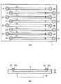
図1(A)は、本発明のプローブ固相化反応アレイを上面から見た平面図である。また、図1(B)は、本態様であるプローブ固相化反応アレイ1をキャピラリ4に沿って切断した断面図である。
【0034】
プローブ固相化反応アレイ1は、透明なガラス製の基板34とシリコン基板35を用いて製造されたプローブ固相化反応アレイの例である。
【0035】
プローブ固相化反応アレイ1の基板の内部には複数のキャピラリ2、3、4、5、6、7、8および9が、同一平面上に並列して平行に形成されている。それぞれのキャピラリは互いに独立して形成されるので、他のキャピラリに含まれる流体と互いに混じり合うことはない。また、それぞれのキャピラリの両端には、開口部が形成されている。具体的には、キャピラリ2、3、4、5、6、7、8および9には、それぞれ試料注入口18、19、20、21、22、23、24および25と、試料排出口26、27、28、29、30、31、32および33が形成されている。キャピラリ2、3、4、5、6、7、8および9の内部には、それぞれの解析項目に応じて適切なプローブ群10〜プローブ群17が固定されている。
【0036】
各アレイは、複数のプローブが固定化されている。これらプローブの配置は、複数列となっている。たとえば、キャピラリ4に複数列でプローブを固定化した例を図2または3に示す。図2は、プローブを3列に固定化した例である。また、図3は、プローブを4列に固定化した例である。プローブを1列おきに同じ配置で4列に固相化した。
【0037】
1つの反応部には、何列でプローブを固相化してもよい。しかし、列数は、スポット径、キャピラリの太さなどによる制限を受けてしまう。たとえば、試料注入、洗浄液などの交換の容易性を考慮すると、実用的には反応部の幅は数ミリ以内が好ましい。また、プローブを20列配置するためには、反応部の幅が約5mm程度必要である。したがって、配列数は、2列以上20列以下が好ましい。
【0038】
複数の反応部を有するプローブ固相化反応アレイは、既に開発されているが、1つの反応部に複数列で同種のプローブが固相化されたアレイは、従来技術にはみられなかった。このように1つの反応部に複数列でプローブを固定化することにより、固定化を行う支持体の形状およびサイズに応じてプローブ密度を向上することができるだけでなく、測定項目数に対して配列数を調整して、それぞれのキャピラリ毎に独自のアレイデザインが可能となるので、多様な反応条件を得ることができるようになる。
【0039】
一方、アレイには、プローブの代わりにマーカを固定化することもできる。マーカは、単なるスポットでもよいが、複数列でアレイにスポットすることにより、記号、数字、文字またはバーコード等を記入するで情報量を増大することもできる。たとえば、図4では、OLYMPUSというアルファベットの文字列をキャピラリ内にスポットした。また、マーカは、アレイの反応部にスポットしてもよく、反応部位外の部分にスポットしてもよい。図4のGMBというアルファベットの文字列は、基板上にスポットした例である。
【0040】
このようなマーカにより、各反応部およびアレイの識別が容易となる。また、マーカとして蛍光マーカを使用することにより、該マーカを蛍光標識された被検試料と共に蛍光イメージ上で確認することができる。また、着色されたマーカを使用すれば、アレイの外見上から識別することもできる。特に、キャピラリ内壁にマーカを付与した場合には、データを測定するときと同様の測定機器または測定操作によってアレイ毎の識別が可能となる。場合によっては、同一の固定化すべき支持体に、プローブの種類と同数のマーカを各プローブ近傍にそれぞれ固定化することにより、同一アレイ上の多数のデータを識別することも可能である。
【0041】
上記マーカは、蛍光色素を使用することが好ましいが、検出方法に応じて種々のマーカを使用することができる。たとえば、蛍光を検出するのであればCy3、FITCおよびCy5等の蛍光色素を使用すればよい。
【0042】
このようなマーカを使用することにより、データ処理時のミスを減少し、効率を向上することができる。
【0043】
上記プローブ固相化反応アレイ1は、たとえば、次のように製造することが可能である。同じ大きさのガラス基板とシリコン基板を用意し、基板34と基板35とする。基板35にエッチングによって溝を形成する。解析項目に応じて所望のプローブを予め準備しておき、これらのプローブを各反応部の溝の底部に対してスポッティングすることによって固定すればよい。一方、基板34には、基板35の溝の両端に対応する部分に対して貫通穴が空けられる。次に、基板34と基板35を接合する。それぞれの開口部に所望の長さのガラス管を接着することにより連結部37aおよび37bを形成する。該連結部は、使用する装置に応じて、ガラス管が接着されていなくてもよく、単に開口部を有するだけであってもよい。キャピラリ形状の空間のサイズは、用途に合わせて種々の大きさに設定することができるが、実用的には幅が10μm〜数mm、深さ1μm〜500μm、長さ数mm〜100mm、キャピラリ間隔10μm〜数mm程度で充分である。ただし、反応の効率性を考えると、測定対象となるmRNA、またはmRNAから合成または逆転写したcDNAなどの核酸の拡散速度は毎秒数μmと遅いので、キャピラリ形状の空間の断面形状は、幅を広くしても深さは浅くするような扁平構造をとることにより、反応時間の短縮、試料の微量化、観察視野の増加等が期待できる。
【0044】
上記の例では、基板35に溝を形成したが、基板34でもよいし基板34と基板35の両方に形成されていてもよい。また、支持体の材料として、蓋として用いる基板にはガラス製基板を使用し、溝を形成する基板にはシリコン基板を使用したが、これに限定されるものではなく、蓋として用いる基板にシリコン基板を使用し、溝を形成する基板にガラス製基板を使用してもよい。また、使用される2枚の基板を同じ材質としてもよい。また、観察の方向に透過性部材が配置されるように、使用する部材を決定してもよい。あるいは、プラスチック樹脂やゴムなどで形成された支持体を使用してもよい。また、これらの材質、ガラス、シリコン、プラスチック樹脂およびゴムなどの材質で形成された支持体を組み合わせて使用してもよい。また、上記の例では支持体として板状の基板を使用しているが、これに限定されるものではない。
【0045】
ガラスやシリコンウエハ様の基板では、たとえば、フォトリソ−エッチングなどの技術により溝および貫通穴を形成することが可能である。また、プラスチック樹脂やゴムなどの場合には機械加工やモールド加工などにより溝および貫通穴を形成することが可能である。
【0046】
また、2枚の基板の接合は、それ自身公知の手段により、プローブの固定の前または固定後に行われればよい。たとえば、核酸プローブを固定前に接合した場合には、光固相化法(たとえば特表平6-504997参照)を適用して核酸プローブを固定化するのが好ましい。たとえば、シリコン−石英ガラスの場合には、接着剤をスクリーン印刷機により印刷して接着すればよい。たとえば、シリコン−パイレックスガラスの場合には、半導体プロセスで使用される陽極接合法により、高温および高電圧の下で接合を行えばよい。
【0047】
上記の例では、基板35の溝の底部にプローブを固定したが、基板34にそれを固定してもよく、また、各反応部の側面にそれを固定してもよい。基板には、プローブを固相化するために適切な表面処理、たとえば、ポリLリジン処理、アミノシラン処理および酸化膜処理等の表面処理を行うことが可能である。
【0048】
プローブの固定手段は、それ自身公知の何れかの手段を使用してもよい。たとえば、核酸プローブの固定化であれば、スポッティング法および光固相化法などを使用してもよい。たとえば、スポッティング法を使用する場合、インクジェット方式スポッターを使用して固定化することができる。反応部の数に応じてインクジェット方式スポッターを自作してもよく、図1のアレイを作製するときであれば8連のインクジェットノズルのものを使用することにより、迅速にスポットすることができる。このような自作のスポット装置を使用することにより、プローブ配置を自在に行うことができる。たとえば、所望の配列数、スポット径、スポットのパターン等に変更可能に設計されたスポッターを使用することにより、最適なスポット数および密度で固定化することができる。
【0049】
さらに、固定化するプローブは、ビーズにあらかじめ固定化されたプローブを使用してもよい。この場合、プローブが固定化されたビーズを基板に固定化することとなる。このようなビーズに所望の核酸プローブを固相するためのプローブ供給手段は、基体の材料により、それ自身公知の何れかの手段を使用することができる。公知の手段を、立体状基体または粒状基体の曲面、特に球面に適用し得るように改良することも可能である。たとえば、曲面体に加工を施した基体上に核酸プローブを配するためには、光固相方式および点着方式の2つの手法を適宜組み合わせて用いることによって曲面の部分領域に対して定量的に核酸プローブを固相することが可能となる。
【0050】
上記ビーズを基板に固定化するには、たとえばそれ自体公知のいずれの手段を使用してもよい。たとえば、ビーズが磁性粒子であれば、あらかじめキャピラリの内部または外方の所望の位置に磁石を固定化しておくことにより、磁力でビーズを固定することも可能である。
【0051】
また、本発明のアレイに固定化されるプローブは、核酸、タンパク質、抗体、抗原または細胞からなる群から選択されるが、好ましくは核酸プローブである。
【0052】
本実施の形態では、プローブ固相化反応アレイ1に含まれる反応部の形状をキャピラリとしたが、この形状に限定されるものではない。たとえば、反応部の形状は、底面が角型、円または楕円であるようなウェル形状であってもよい。
【0053】
また、本発明のプローブ固相化反応アレイは、上記キャピラリ形状およびウェル形状の他に、物理的に互いに隔離された反応部が形成されたデバイス構造の種々の構造であってもよい。上記例では、プローブ固相化反応アレイ1に含まれる反応部を8つとし、反応部のそれぞれに試料注入口および/または試料排出口として使用できる1以上の開口部を形成したが、この数に限定されるものではなく、複数の反応部を具備すればよい。すなわち、互いに独立した反応部を有していればよく、たとえば、凹部または凸部により仕切られた領域に開口部を有する蓋または底部を配置し、有効容積のある反応部を形成すればよい。
【0054】
また、基板内部に反応部を形成した閉鎖系の反応アレイのみでなく、単に凹部または凸部により仕切られた容器に対しても、または平面からなる特に仕切のない領域であっても、互いに独立し、かつ任意の方向に並列して複数の反応部を支持体に備え、充分に離間しているかあるいは多数の垂直孔によって液の拡散が妨げられていれば本発明の態様に使用することが可能である。このような装置およびその使用も本発明の範囲に含まれる。
【0055】
また、本実施の形態では、ヒータが本発明に従う反応アレイと別体である1例を示したが、ヒータおよびセンサ並びに必要な配線等が反応アレイ中に組み込まれていてもよく、これを具備していない反応アレイであってもよい。
【0056】
次に、本発明に従うプローブ固相化アレイを用いて、個体における標的物質に関する情報を得る方法も提供される。
【0057】
そのような方法は、たとえば、以下のように行うことが可能である。まず、それ自身公知の手段により個体から被検試料を得る。次に、本発明に従うプローブ固相化反応アレイに具備される反応部の所望する数の反応部、または所望する数の複数のプローブ固相化反応アレイに対して被検試料を添加する。被検試料は、後で検出できるように追跡可能な光学的または物理的標識が行われていることが望ましい。したがって、上記追跡可能な標識物、たとえば、蛍光色素、発光色素等を使用して、あらかじめ被検試料を標識しておくことが好ましい。標的核酸を含む被検試料の標識は、たとえば、標的物質が核酸であれば、蛍光標識されたデオキシヌクレオチド三リン酸(dUTP)を取り込みながら標識を行う方法を使用するか、またはあらかじめ蛍光標識されたプライマーにより増幅を行って、標識物を導入する方法を使用することができる。その他にも、増幅後に色素を結合させる方法などを使用することができるが、これらに限定されない。使用可能な標識としては、Cy3、FITCおよびCy5等があるが、これらに限定されるものではない。たとえば、ハイブリダイゼーションの検出方法として、ハイブリダイゼーション後の偏光性の変化を検出する方法を使用可能する場合等には、非標識のまま標的核酸を使用することもできる。
【0058】
標的核酸として1種類の標的核酸だけでなく、2種類以上の標的核酸を混合させて行うことも可能である。この場合は、数種類の標識で標的核酸を標識してもよい。また、各反応部毎に標識の種類を変更して反応を行ってもよい。
【0059】
次いで、被検試料を添加した反応部における反応条件を、各反応部に具備されるプローブ群の各々の至適反応条件となるように反応条件の制御を行いながら、プローブと標的物質とを反応させる。
【0060】
至適反応条件は、当業者であれば容易に制御可能であろう。たとえば、図1のプローブ固相化反応アレイ1において、それぞれのキャピラリに具備されるプローブをプローブのTmによって分類した場合、それぞれのキャピラリ毎に温度を制御する。至適温度の条件は、各キャピラリ毎にヒータにより調節することもできる。
【0061】
また、全ての反応部を一定の温度に維持してイオン濃度および塩濃度により至適反応条件を得てもよい。たとえば、至適反応温度の異なる全ての反応部について一定温度でハイブリダイズさせる場合には、ハイブリダイゼーション時に使用する反応液を調節すればよい。すなわち、核酸ハイブリダイゼーションを行う場合に、各反応部の至適濃度が異なっているときであっても、標的核酸を含む被検試料の溶液として使用する緩衝液等の塩濃度を反応部毎に調節することによって達成することが可能である。
【0062】
続いて、プローブと標的物質の結合を検出することによって、被検試料中に標的物質が存在することを検出する。この検出は、使用する標識物質に応じたそれ自身公知の手段により行うことが可能である。
【0063】
次に、検出により得られた結果から、個体における標的物質に関する情報を得ることによって、個体における標的物質に関する情報を得る。
【0064】
このような方法により得られる情報は、対象となる個体の遺伝子発現に関する情報、ゲノムに関する情報、蛋白質発現に関する情報、抗原抗体などに関する免疫情報、並びに感染や疾病に関する情報などであるが、これに限定されるものではない。所望する情報を得るためのプローブは、予め設計または選択しておけばよい。
【0065】
上記方法の実施の際に、上記マーカを固定化したアレイを使用すれば、その使用態様により、反応後のデータ処理をとり間違えることなく効率的に行うことができる。
【0066】
また、自動化装置によれば、上記方法を自動で実施することもできる。
【0067】
上記方法は、たとえば、特願2002-034197に記載の処理装置にしたがって実施することもできる。
【0068】
従来の方法では、1つの反応部に固定されるプローブ数が制限されていたが、本発明のプローブ固相化反応アレイを使用することにより、より多くのプローブについて解析可能な方法が提供される。
【0069】
【実施例】
(実施の様態1)
図1は本発明の実施例である。本実施例ではスポットの状態がよくわかるように蛍光色素を試料としてスポットした。スポットに用いた装置は自作の8連のインクジェット方式スポッターである。この装置は25μmの位置精度で任意の位置にスポット可能でかつ、8連のインクジェットノズルは独立にスポット動作する。スポット配置は、制御用コンピュータ上で望みのスポット数および配置パターンでアレイデザインが出来るようになっている。また、本実施例の装置は、スポット径を80μmまで縮小可能である。試料をスポットした後、市販の蛍光スキャナー(Scan array 4000)で蛍光イメージを読みとった。このようなスポッターの改良は、たとえば特願2002-135284の記載にしたがって製造することができる。
【0070】
図4は、大きく8本のDNAプローブ配列を固定化した模式図である。この8本がDNAキャピラリの溝構造に相当し、おのおの独立した反応部となる。各反応部は、3列にDNAプローブが配置されている。また、図の上端にはGMB、左から8本目のキャピラリに相当する位置にはOLYMPUSとアルファベットでスポットした。
【0071】
この図から分かるように、自作のスポット装置を使用することによりDNAプローブの配置を自在に行うことが出きる。また、1本のキャピラリ中に複数列でプローブを配置することができる。
【0072】
【発明の効果】
上記のような状況に鑑み、本発明は、多様な反応条件が得られ、且つ反応後のデータ処理を取り違えることなく効率的に行うことができるプローブ固相化アレイを提供することを目的とする。
【0073】
これまでのマイクロアレイ解析では、複数項目の解析を同時に行うことが困難であったが、本発明により、省資源化、低コスト化が図られ、迅速に精度良く、遺伝子発現頻度および遺伝子多型解析等のハイブリダイゼーションを基本とした解析を行うことが可能となる。従来別々のアレイ上で行っていた検査について、一度に解析が可能となり、たとえば、検査の効率化が図れるとともに、解析時における個人データの取り扱いについてミスが少なくなるであろう。
【0074】
また、キャピラリアレイでは、反応自動化装置を使用することにより、多数キャピラリでの反応を自動で行うことが可能である。したがって、多量検体の解析もハイスループットで行うことが可能である。
【図面の簡単な説明】
【図1】本発明の一実施形態に係るプローブ固相化反応アレイを示す図。
【図2】本発明のプローブ固相化反応アレイの反応部の拡大図。
【図3】本発明のプローブ固相化反応アレイの反応部の拡大図。
【図4】本発明の一実施形態に係るプローブ固相化反応アレイを示す図。
【符号の説明】
1 プローブ固相化反応アレイ
2,3,4,5,6,7,8,9 キャピラリ(反応部)
10,11,12,13,14,15,16,17 プローブ群
18,19,20,21,22,23,24,25 試料注入口
26,27,28,29,30,31,32,33 試料排出口
34,35 基板
36 ヒータ
37a、37b 連結部[0001]
BACKGROUND OF THE INVENTION
The present invention relates to a probe-immobilized reaction array. Specifically, the present invention relates to a probe-immobilized reaction array for use in analysis of nucleic acids and proteins.
[0002]
[Prior art]
The basic principle of DNA microarrays is to fix a large number of different DNA targets on a solid phase substrate such as glass at high density. A labeled DNA is hybridized thereon, the signal from each probe is detected by an automatic detector, and the data is analyzed in large quantities by a computer. DNA microarrays are expected to provide mass analysis, improved detection sensitivity, sample saving through microfabrication, automation of data acquisition, and simplification through data processing. There are two types of DNA microarrays: DNA type (DNA chip) that synthesizes DNA on the glass surface (Non-patent Document 1), and type that DNA is prepared in advance (DNA microarray) (Non-patent document). Reference 2). DNA microarrays that attach DNA to glass slides do not require large-scale semiconductor manufacturing machines, but can be done with DNA array machines and detectors. The advantage is that the DNA to be attached can be arbitrarily selected, but there is the complexity of having to prepare a collection of DNA. Although the density of DNA is inferior to that of the optical lithography method because it is physically spotted at the tip of the pin, even if, for example, spots with a diameter of 100 μm are spotted at 100 μm intervals, the calculation is 1 cm.22500 spots are possible, normal glass slide l (effective area is about 4cm2) Can carry about 10,000 DNA.
[0003]
An array machine is basically a combination of a high-performance servomotor and a pin tip or slide holder operated in the XYZ axis direction under computer control to carry a DNA sample from the microtiter plate onto the slide glass surface. Many innovations have been made in the shape of the pin tip, which can be said to be the life of this technology. The most common is the shape of a nib that is broken like a crow mouth, where the DNA solution is stored and spotted on multiple slides. Repeat the process of placing the next DNA sample across the wash / dry cycle. The functions required for an ideal array machine are that the spot size and shape are uniform, and that the reproducibility is high at high speed. Because there are limits to uniformity and speed due to differences in the lots of pin tips, new technologies such as inkjet and capillary methods are being developed for higher performance.
[0004]
Regarding the DNA immobilization method, various coatings have been attempted because glass is softer than a membrane and has an effective immobilization area and a small charge charge. Practically, poly L lysine or silanization is used. There is also a method in which DNA ends are aminated and cross-linked to silanized glass.
[0005]
The probe DNA is usually labeled with Cy3-dUTP or Cy5-dUTP when cDNA is synthesized from mRNA or total RNA extracted from tissues or cells. Labeling is often used when first-strand cDNA is synthesized using an oligo dT primer or a random primer and reverse transcriptase. The mainstream of gene expression analysis currently being performed is a system that observes differential gene expression using the two-fluorescence labeling method. The principle is that to detect the difference in gene expression in two different mRNA samples, each labeled with a different fluorescence and competitive hybridization on the array to measure and compare both fluorescence Is.
[0006]
In recent years, a protein chip in which a plurality of proteins and peptides are immobilized has been developed. For example, Non-Patent
[0007]
As described above, in DNA analysis, a large number of different DNA probes are immobilized on a solid substrate such as glass at high density, and labeled DNA is hybridized thereon, and signals from each probe are automatically detected. The data is detected by a vessel and the data is analyzed in large quantities by a computer. These have the following problems.
[0008]
In general, the reaction conditions of many immobilized DNA probes are not constant. Strictly speaking, DNA hybridization reaction conditions are affected by the base sequence and constituent bases of double-stranded DNA formed during the reaction. The temperature at which double-stranded DNA is cleaved into single strands is referred to as Tm (melting temperature), and is roughly determined by the number of hydrogen bonds and the surrounding ion concentration. Regarding DNA bases, there are 3 hydrogen bonds for GC bonds and 2 sites for AT bonds, so Tm varies depending on the GC content even for DNA of the same length. Further, Tm increases when the salt concentration in the solution is increased. For example, if the salt concentration is changed 10 times, Tm changes 10 times.
[0009]
In view of such a problem, the inventors have devised a chip that can provide a plurality of reaction regions, group DNA probes for each reaction condition, and perform a reaction under optimum reaction conditions for each. However, with regard to DNA probes to be immobilized, it cannot be said that the application conditions such as the performance of the spotter used and the shape and size of the support to be spotted are optimized, so the number and density of probes are limited. End up. On the other hand, there is a need to fix more DNA probes. In addition, with the increase in the number of solid-phased DNA probes, the importance of identification markers for reliably and efficiently performing data processing after reaction is also increasing.
[0010]
[Patent Document 1]
JP 2000-135081 A
[0011]
[Non-Patent Document 1]
Pease AC, Solas D, Sullivan EJ, Cronin MT, Holmes CP, Fodor SP., Light-generated oligonucleotide arrays for rapid DNA sequence analysis. “Proc Natl Acad Sci USA” (USA), 1994, 91, p. .5022-5026
[0012]
[Non-Patent Document 2]
Schena M, Shalon D, Davis RW, Brown PO., Quantitative monitoring of gene expression patterns with a complementary DNA microarray., “Science”, (USA), 1995, 270, p.467-470
[0013]
[Non-Patent Document 3]
Service RF., Biochemistry. Protein arrays step out of DNA's shadow., “Science”, (USA), 2000, 289 (5485), p.1673
[0014]
[Problems to be solved by the invention]
In view of the above situation, an object of the present invention is to provide a probe-immobilized array in which various reaction conditions can be obtained and data processing after the reaction can be performed efficiently without being mistaken. .
[0015]
[Means for Solving the Problems]
In a conventional probe-immobilized reaction array having a capillary shape or the like, the number of probes immobilized on each reaction part is limited. In view of this, the inventors have focused on the fact that the probe density can be improved by immobilizing the probes in one reaction section in a plurality of rows, and the present invention has been completed.
[0016]
In addition, improvements in spotting devices for solid-phase DNA probes have progressed, and devices capable of precisely spotting any position on a substrate with a small diameter have been developed. Flexible DNA probe placement was made possible. With such improvements, the present invention has been completed by paying attention to the fact that probes can be immobilized in a plurality of sequences in each reaction section and fluorescent markers can be spotted.
[0017]
That is, in one embodiment of the present invention, a probe-immobilized reaction array in which probes are immobilized on a support,
The support comprises a plurality of first to nth reaction parts (where n is an integer of 2 or more) formed independently on the support,
A plurality of probes are immobilized on the reaction part,
There is provided a probe-immobilized reaction array characterized in that the probes are arranged in a plurality of rows.
[0018]
The probe-immobilized reaction array is provided with a probe-immobilized reaction array characterized in that a plurality of rows are 2 rows or more and 20 rows or less.
[0019]
Furthermore, the probe-immobilized reaction array is provided with a probe-immobilized reaction array characterized in that a marker for reporting information is spotted in addition to the DNA probe spotted at an arbitrary position in the reaction part. .
[0020]
Furthermore, the probe-immobilized reaction array is provided, wherein the marker is a fluorescent marker.
[0021]
Furthermore, the probe-immobilized reaction array is provided, wherein the reaction portion has a capillary shape or a well shape.
[0022]
Furthermore, the probe-immobilized reaction array provides a probe-immobilized reaction array in which the probe is indirectly immobilized on a support by a probe fixed to a bead.
[0023]
Furthermore, in the probe-immobilized reaction array, the probe immobilized on the reaction part is one or more probes selected from a probe group consisting of nucleic acid, protein, antibody or antigen. Providing a probe-immobilized reaction array is provided.
[0024]
In another embodiment of the present invention, there is provided a method for detecting a target substance using the probe-immobilized reaction array,
(1) adding a test sample to the first to nth reaction parts provided in the probe-immobilized reaction array;
(2) reacting the probe with the target substance while controlling the reaction conditions in the first to nth reaction parts according to the optimum reaction conditions of each reaction part;
(3) detecting the presence of the target substance in the test sample by detecting the binding between the probe and the target substance;
A method comprising:
[0025]
Furthermore, the present invention provides a method for detecting a target substance using the probe-immobilized reaction array, wherein the injection reagent or the test sample is fluorescently labeled.
[0026]
Furthermore, the present invention provides a method for detecting a target substance using the probe-immobilized reaction array, wherein the analysis is performed by an automated apparatus.
[0027]
According to such a structure, since one optimum reaction condition can be applied to each reaction part, that is, for each probe group, the best reaction result can be obtained for any probe group. In addition, the number of probes in one probe group can be increased as compared with the conventional array, and not only the reproducibility of the probe-immobilized array but also the reaction efficiency is remarkably improved.
[0028]
DETAILED DESCRIPTION OF THE INVENTION
As used herein, the term “nucleic acid” refers to artificially synthesized various naturally occurring DNAs and RNAs, as well as peptide nucleic acids, morpholino nucleic acids, methyl phosphonate nucleic acids and S-oligonucleic acids. Nucleic acid analogues and the like.
[0029]
As used herein, the term “target substance” refers to a substance to be detected by a probe. For example, nucleic acids, proteins and the like are included, and more specifically, peptides, antigens and antibodies are also included. In general, a nucleic acid probe is designed to have a base sequence complementary to a target nucleic acid. If the target substance is an antigen, an antibody that can specifically bind to the antigen is used as a probe. When the test nucleic acid contained in the test sample has the base sequence of the target sequence, hybridization occurs between the nucleic acid probe and the target sequence. Therefore, the nucleic acid contained in the test sample can be analyzed by detecting this hybridization. Hybridization may be detected by means known per se. The base sequence that becomes the target of the target nucleic acid is referred to as “target sequence”.
[0030]
As used herein, the term “test sample” refers to a sample prepared from a biological sample such as cells, tissues, organs, blood, serum, lymph, tissue, hair and earwax collected from an individual as desired. Also, it refers to a sample to be subjected to a test that contains a substance that is artificially synthesized or manufactured. The “test sample” may be a sample obtained by subjecting a biological sample to any necessary pretreatment such as homogenate and extraction as necessary. Such pretreatment could be selected by one skilled in the art depending on the biological sample of interest.
[0031]
As used herein, the term “individual” refers to any mammal, including humans, dogs, cats, cows, goats, pigs, sheep, and monkeys, and non-mammalian organisms such as plants and insects.
[0032]
Hereinafter, the probe-immobilized reaction array of the present invention will be described with reference to an example in which the reaction part is a capillary-shaped array (FIG. 1).
[0033]
FIG. 1 (A) is a plan view of the probe-immobilized reaction array of the present invention as viewed from above. FIG. 1B is a cross-sectional view of the probe-immobilized
[0034]
The probe-immobilized
[0035]
A plurality of
[0036]
Each array has a plurality of probes immobilized thereon. These probes are arranged in a plurality of rows. For example, FIG. 2 or 3 shows an example in which the probe is fixed to the
[0037]
In one reaction part, the probes may be immobilized in any number of rows. However, the number of rows is limited by the spot diameter, capillary thickness, and the like. For example, considering the ease of sample injection and replacement of the cleaning solution, the width of the reaction section is preferably within a few millimeters in practice. In addition, in order to arrange 20 rows of probes, the width of the reaction part is required to be about 5 mm. Therefore, the number of arrangements is preferably 2 or more and 20 or less.
[0038]
A probe-immobilized reaction array having a plurality of reaction units has already been developed, but an array in which the same kind of probes is immobilized in a plurality of rows in one reaction unit has not been found in the prior art. In this way, by immobilizing probes in multiple rows in one reaction part, not only can the probe density be improved according to the shape and size of the support to be immobilized, but also the number of measurement items can be arranged. By adjusting the number, a unique array design can be made for each capillary, so that various reaction conditions can be obtained.
[0039]
On the other hand, a marker can be fixed to the array instead of the probe. The marker may be a simple spot, but the amount of information can be increased by writing a symbol, number, character, barcode, or the like by spotting the array in a plurality of rows. For example, in FIG. 4, an alphabetic character string OLYMPUS was spotted in the capillary. The marker may be spotted on the reaction part of the array or may be spotted on a part outside the reaction site. The alphabetic character string “GMB” in FIG. 4 is an example of spotting on the substrate.
[0040]
Such a marker facilitates identification of each reaction part and the array. Further, by using a fluorescent marker as a marker, the marker can be confirmed on a fluorescent image together with a fluorescently labeled test sample. In addition, if colored markers are used, they can be identified from the appearance of the array. In particular, when a marker is attached to the inner wall of the capillary, it is possible to identify each array by the same measuring instrument or measuring operation as that for measuring data. In some cases, it is also possible to identify a large number of data on the same array by immobilizing the same number of markers as the type of probe on the same support to be immobilized.
[0041]
The marker is preferably a fluorescent dye, but various markers can be used depending on the detection method. For example, if fluorescence is detected, fluorescent dyes such as Cy3, FITC, and Cy5 may be used.
[0042]
By using such a marker, mistakes during data processing can be reduced and efficiency can be improved.
[0043]
The probe-immobilized
[0044]
In the above example, the groove is formed in the
[0045]
In a glass or silicon wafer-like substrate, for example, grooves and through holes can be formed by a technique such as photolithography-etching. In the case of plastic resin or rubber, the grooves and through holes can be formed by machining or molding.
[0046]
Further, the two substrates may be joined by means known per se before or after the probe is fixed. For example, when the nucleic acid probe is joined before immobilization, it is preferable to immobilize the nucleic acid probe by applying a photo-solid phase method (see, for example, JP 6-504997). For example, in the case of silicon-quartz glass, an adhesive may be printed by a screen printer and bonded. For example, in the case of silicon-pyrex glass, bonding may be performed under high temperature and high voltage by an anodic bonding method used in a semiconductor process.
[0047]
In the above example, the probe is fixed to the bottom of the groove of the
[0048]
Any means known per se may be used as the probe fixing means. For example, as long as the nucleic acid probe is immobilized, a spotting method, a photo-solid phase method, or the like may be used. For example, when using a spotting method, it can be immobilized using an ink jet spotter. Depending on the number of reaction parts, an ink jet spotter may be made by itself, and if an array of FIG. 1 is produced, spotting can be quickly performed by using an eight ink jet nozzle. By using such a self-made spot device, probe arrangement can be performed freely. For example, by using a spotter designed to be changeable to a desired number of arrays, spot diameter, spot pattern, etc., it is possible to fix the spot with the optimum number of spots and density.
[0049]
Further, as the probe to be immobilized, a probe previously immobilized on a bead may be used. In this case, the beads on which the probes are immobilized are immobilized on the substrate. As the probe supply means for immobilizing a desired nucleic acid probe on such beads, any means known per se can be used depending on the material of the substrate. It is also possible to improve the known means so that it can be applied to the curved surface of a solid substrate or a granular substrate, in particular a spherical surface. For example, in order to place a nucleic acid probe on a substrate having a curved body processed, a combination of two methods, a photosolid phase method and a spotting method, can be used quantitatively with respect to a curved partial region. The nucleic acid probe can be solid-phased.
[0050]
In order to immobilize the beads on the substrate, for example, any means known per se may be used. For example, if the beads are magnetic particles, it is possible to fix the beads with a magnetic force by fixing the magnet in a desired position inside or outside the capillary in advance.
[0051]
The probe immobilized on the array of the present invention is selected from the group consisting of nucleic acids, proteins, antibodies, antigens or cells, but is preferably a nucleic acid probe.
[0052]
In the present embodiment, the shape of the reaction part included in the probe-immobilized
[0053]
Further, the probe-immobilized reaction array of the present invention may have various device structures in which reaction portions that are physically separated from each other are formed in addition to the capillary shape and the well shape. In the above example, eight reaction parts are included in the probe-immobilized
[0054]
In addition to a closed reaction array in which a reaction part is formed inside a substrate, it is also independent of a container partitioned simply by a concave part or a convex part, or even in a non-partitioned area consisting of a plane. In addition, if the support is provided with a plurality of reaction parts arranged in parallel in an arbitrary direction and is sufficiently separated or prevented from diffusing liquid by a large number of vertical holes, it can be used in the embodiment of the present invention. Is possible. Such devices and their uses are also within the scope of the present invention.
[0055]
In the present embodiment, an example is shown in which the heater is separate from the reaction array according to the present invention. However, the heater, sensor, and necessary wiring may be incorporated in the reaction array. An unreacted reaction array may be used.
[0056]
Next, a method for obtaining information on a target substance in an individual using the probe-immobilized array according to the present invention is also provided.
[0057]
Such a method can be performed as follows, for example. First, a test sample is obtained from an individual by means known per se. Next, a test sample is added to a desired number of reaction units of the reaction unit provided in the probe-immobilized reaction array according to the present invention or a desired number of probe-immobilized reaction arrays. The test sample is preferably optically or physically labeled so that it can be detected later. Therefore, it is preferable to label the test sample in advance using the traceable label, for example, a fluorescent dye or a luminescent dye. For the labeling of the test sample containing the target nucleic acid, for example, if the target substance is a nucleic acid, a method of labeling while incorporating fluorescently labeled deoxynucleotide triphosphate (dUTP) is used, or fluorescent labeling is performed in advance. It is possible to use a method in which a label is introduced by performing amplification using a primer. In addition, although the method etc. which couple | bond a pigment | dye after amplification can be used, it is not limited to these. Examples of usable labels include, but are not limited to, Cy3, FITC, and Cy5. For example, when a method for detecting a change in polarization after hybridization can be used as a method for detecting hybridization, the target nucleic acid can be used without labeling.
[0058]
It is possible to mix not only one type of target nucleic acid but also two or more types of target nucleic acids as the target nucleic acid. In this case, the target nucleic acid may be labeled with several types of labels. Moreover, you may react by changing the kind of label | marker for every reaction part.
[0059]
Next, the reaction between the probe and the target substance is performed while controlling the reaction conditions so that the reaction conditions in the reaction section to which the test sample is added become the optimum reaction conditions for each probe group provided in each reaction section. Let
[0060]
Optimum reaction conditions can be readily controlled by those skilled in the art. For example, in the probe-immobilized
[0061]
Alternatively, all reaction parts may be maintained at a constant temperature to obtain optimum reaction conditions based on the ion concentration and salt concentration. For example, when all the reaction parts having different optimum reaction temperatures are hybridized at a constant temperature, the reaction solution used at the time of hybridization may be adjusted. That is, when nucleic acid hybridization is performed, even when the optimum concentration of each reaction part is different, the salt concentration of a buffer solution or the like used as a solution of a test sample containing the target nucleic acid is set for each reaction part. It can be achieved by adjusting.
[0062]
Subsequently, the presence of the target substance in the test sample is detected by detecting the binding between the probe and the target substance. This detection can be performed by means known per se according to the labeling substance used.
[0063]
Next, information on the target substance in the individual is obtained by obtaining information on the target substance in the individual from the result obtained by the detection.
[0064]
Information obtained by such a method includes information on the gene expression of the target individual, information on the genome, information on protein expression, immunity information on antigen antibodies, etc., information on infection and disease, etc. Is not to be done. A probe for obtaining desired information may be designed or selected in advance.
[0065]
When the above-described method is used, if an array in which the marker is immobilized is used, the data processing after the reaction can be performed efficiently without making a mistake depending on the usage mode.
[0066]
Moreover, according to the automation apparatus, the above method can be automatically performed.
[0067]
The above method can also be performed, for example, according to the processing apparatus described in Japanese Patent Application No. 2002-034197.
[0068]
In the conventional method, the number of probes immobilized on one reaction unit is limited, but by using the probe-immobilized reaction array of the present invention, a method capable of analyzing more probes is provided. .
[0069]
【Example】
(Mode 1)
FIG. 1 shows an embodiment of the present invention. In this example, a fluorescent dye was spotted as a sample so that the state of the spot could be clearly understood. The device used for the spot is a self-made eight-line inkjet spotter. This apparatus can spot an arbitrary position with a position accuracy of 25 μm, and the eight ink jet nozzles independently spot. In the spot arrangement, an array design can be performed with a desired number of spots and arrangement pattern on the control computer. Moreover, the apparatus of the present embodiment can reduce the spot diameter to 80 μm. After spotting the sample, the fluorescence image was read with a commercially available fluorescence scanner (Scan array 4000). Such an improved spotter can be manufactured, for example, according to the description in Japanese Patent Application No. 2002-135284.
[0070]
FIG.FIG. 4 is a schematic diagram in which eight DNA probe sequences are largely immobilized. These eight correspond to the groove structure of the DNA capillary, and each becomes an independent reaction part. In each reaction part, DNA probes are arranged in three rows. Also, GMB was spotted at the upper end of the figure, and OLYMPUS was spotted at the position corresponding to the eighth capillary from the left.
[0071]
As can be seen from this figure, it is possible to freely arrange DNA probes by using a self-made spot device. In addition, probes can be arranged in a plurality of rows in one capillary.
[0072]
【The invention's effect】
In view of the above situation, an object of the present invention is to provide a probe-immobilized array in which various reaction conditions can be obtained and data processing after the reaction can be performed efficiently without being mistaken. .
[0073]
In conventional microarray analysis, it has been difficult to analyze multiple items at the same time. However, according to the present invention, resource saving and cost reduction can be achieved, and gene expression frequency and gene polymorphism analysis can be performed quickly and accurately. Analysis based on such hybridization can be performed. Tests that have been performed on separate arrays in the past can be analyzed at once. For example, the efficiency of the test can be improved, and errors in handling personal data during analysis will be reduced.
[0074]
Moreover, in a capillary array, it is possible to automatically perform reactions in a large number of capillaries by using a reaction automation device. Therefore, analysis of a large amount of samples can be performed with high throughput.
[Brief description of the drawings]
FIG. 1 is a diagram showing a probe-immobilized reaction array according to an embodiment of the present invention.
FIG. 2 is an enlarged view of the reaction part of the probe-immobilized reaction array of the present invention.
FIG. 3 is an enlarged view of a reaction part of the probe-immobilized reaction array of the present invention.
FIG. 4 is a diagram showing a probe-immobilized reaction array according to an embodiment of the present invention.
[Explanation of symbols]
1 Probe-immobilized reaction array
2, 3, 4, 5, 6, 7, 8, 9 Capillary (reaction part)
10, 11, 12, 13, 14, 15, 16, 17 Probe group
18, 19, 20, 21, 22, 23, 24, 25 Sample inlet
26, 27, 28, 29, 30, 31, 32, 33 Sample outlet
34, 35 substrate
36 Heater
37a, 37b Connecting part
Claims (5)
Translated fromJapanese前記支持体は、前記支持体に独立して形成された第1から第nまでの複数の反応部(ここでnは2以上の整数である)を互いに独立して具備するとともに、
各反応部には、複数列からなる同種のプローブが、反応部ごとに異なるスポット数および密度で固定化され、
前記蛍光マーカが、情報を示すための数字、文字およびバーコードから選ばれた複数列のスポットからなる蛍光マーカであることを特徴とするプローブ固相化アレイ。A probe-immobilized reaction array in which a probeand a fluorescent marker are immobilized on a support,
The support comprises a plurality of first to n-th reaction portions (where n is an integer of 2 or more) independently formed on the support, and
In each reaction part, the same type of probes consisting of a plurality of rows are immobilized at different spot numbers and densities for each reaction part,
The probe-immobilized array, wherein the fluorescent marker is a fluorescent marker composed of a plurality of spots selected from numbers, characters and barcodes for indicating information .
Priority Applications (1)
| Application Number | Priority Date | Filing Date | Title |
|---|---|---|---|
| JP2003128266AJP4262512B2 (en) | 2003-05-06 | 2003-05-06 | Probe-immobilized reaction array |
Applications Claiming Priority (1)
| Application Number | Priority Date | Filing Date | Title |
|---|---|---|---|
| JP2003128266AJP4262512B2 (en) | 2003-05-06 | 2003-05-06 | Probe-immobilized reaction array |
Publications (2)
| Publication Number | Publication Date |
|---|---|
| JP2004333255A JP2004333255A (en) | 2004-11-25 |
| JP4262512B2true JP4262512B2 (en) | 2009-05-13 |
Family
ID=33504486
Family Applications (1)
| Application Number | Title | Priority Date | Filing Date |
|---|---|---|---|
| JP2003128266AExpired - Fee RelatedJP4262512B2 (en) | 2003-05-06 | 2003-05-06 | Probe-immobilized reaction array |
Country Status (1)
| Country | Link |
|---|---|
| JP (1) | JP4262512B2 (en) |
Families Citing this family (5)
| Publication number | Priority date | Publication date | Assignee | Title |
|---|---|---|---|---|
| FR2856047B1 (en)* | 2003-06-16 | 2005-07-15 | Commissariat Energie Atomique | METHOD FOR BONDING MICRO-STRUCTURED SUBSTRATES |
| JP5248394B2 (en)* | 2009-03-30 | 2013-07-31 | シャープ株式会社 | Method of immobilizing analyte substance and microanalyzer |
| EP3669985B1 (en) | 2014-06-05 | 2022-02-02 | Illumina, Inc. | Systems including a rotary valve for at least one of sample preparation or sample analysis |
| WO2016152702A1 (en)* | 2015-03-24 | 2016-09-29 | 国立大学法人名古屋大学 | Analytical device |
| JP7503817B2 (en)* | 2019-07-22 | 2024-06-21 | 国立大学法人東海国立大学機構 | Analytical Devices |
- 2003
- 2003-05-06JPJP2003128266Apatent/JP4262512B2/ennot_activeExpired - Fee Related
Also Published As
| Publication number | Publication date |
|---|---|
| JP2004333255A (en) | 2004-11-25 |
Similar Documents
| Publication | Publication Date | Title |
|---|---|---|
| US6929944B2 (en) | Analysis using a distributed sample | |
| US6623696B1 (en) | Biochip, apparatus for detecting biomaterials using the same, and method therefor | |
| US20030138969A1 (en) | Closed substrate platforms suitable for analysis of biomolecules | |
| US20090239769A1 (en) | Expression Miniarrays and Uses Thereof | |
| JP2003107083A (en) | Rod-shaped carrier and cylindrical reaction container provided therewith | |
| US20080207461A1 (en) | Devices for Conducting and Analyzing Microarray Experiments | |
| US20050106607A1 (en) | Biochip containing reaction wells and method for producing same and use thereof | |
| US7253006B2 (en) | Device and method for manufacturing bead array, and method for detecting target substance | |
| JP2003232791A (en) | Probe solid-phase reaction array | |
| JP2004520052A (en) | Biochemical methods and devices for detecting genetic characteristics | |
| JP2004520052A5 (en) | ||
| JP4262512B2 (en) | Probe-immobilized reaction array | |
| JP2004527735A5 (en) | ||
| EP1933138A1 (en) | Biological assay substrate and method and device for producing such substrate | |
| US20070141576A1 (en) | Biological chip and use thereof | |
| JP5092405B2 (en) | Selective binding substance immobilization carrier | |
| JP2007285828A (en) | Method of stirring specimen solution | |
| US20100041165A1 (en) | Probe-immobilized carrier storing manufacturing condition data and manufacturing method and apparatus thereof, detecting method of target substance by use of the probe-immobilized carrier, and measuring apparatus, recording medium, kit and system for use in the detecting method | |
| JP2007304094A (en) | Analytical chip | |
| JP2008134188A (en) | Probe solidifying reaction array and manufacturing method of array | |
| JP2003021637A (en) | Dna chip provided with cover plate | |
| JP2008134189A (en) | Probe solidifying reaction array and manufacturing method of array | |
| JP4167431B2 (en) | Inspection board for biochemical inspection | |
| JP5145752B2 (en) | Analysis chip | |
| JP2005030927A (en) | Bio-related molecular microarray |
Legal Events
| Date | Code | Title | Description |
|---|---|---|---|
| A621 | Written request for application examination | Free format text:JAPANESE INTERMEDIATE CODE: A621 Effective date:20060428 | |
| A977 | Report on retrieval | Free format text:JAPANESE INTERMEDIATE CODE: A971007 Effective date:20080529 | |
| A131 | Notification of reasons for refusal | Free format text:JAPANESE INTERMEDIATE CODE: A131 Effective date:20080603 | |
| A521 | Written amendment | Free format text:JAPANESE INTERMEDIATE CODE: A523 Effective date:20080804 | |
| A131 | Notification of reasons for refusal | Free format text:JAPANESE INTERMEDIATE CODE: A131 Effective date:20081007 | |
| A521 | Written amendment | Free format text:JAPANESE INTERMEDIATE CODE: A523 Effective date:20081208 | |
| TRDD | Decision of grant or rejection written | ||
| A01 | Written decision to grant a patent or to grant a registration (utility model) | Free format text:JAPANESE INTERMEDIATE CODE: A01 Effective date:20090120 | |
| A01 | Written decision to grant a patent or to grant a registration (utility model) | Free format text:JAPANESE INTERMEDIATE CODE: A01 | |
| A61 | First payment of annual fees (during grant procedure) | Free format text:JAPANESE INTERMEDIATE CODE: A61 Effective date:20090209 | |
| FPAY | Renewal fee payment (event date is renewal date of database) | Free format text:PAYMENT UNTIL: 20120220 Year of fee payment:3 | |
| FPAY | Renewal fee payment (event date is renewal date of database) | Free format text:PAYMENT UNTIL: 20120220 Year of fee payment:3 | |
| FPAY | Renewal fee payment (event date is renewal date of database) | Free format text:PAYMENT UNTIL: 20120220 Year of fee payment:3 | |
| FPAY | Renewal fee payment (event date is renewal date of database) | Free format text:PAYMENT UNTIL: 20130220 Year of fee payment:4 | |
| FPAY | Renewal fee payment (event date is renewal date of database) | Free format text:PAYMENT UNTIL: 20140220 Year of fee payment:5 | |
| S531 | Written request for registration of change of domicile | Free format text:JAPANESE INTERMEDIATE CODE: R313531 | |
| R350 | Written notification of registration of transfer | Free format text:JAPANESE INTERMEDIATE CODE: R350 | |
| LAPS | Cancellation because of no payment of annual fees |