JP4262410B2 - Electrical transmission electrode assembly with low initial resistance - Google Patents
Electrical transmission electrode assembly with low initial resistanceDownload PDFInfo
- Publication number
- JP4262410B2 JP4262410B2JP2000529294AJP2000529294AJP4262410B2JP 4262410 B2JP4262410 B2JP 4262410B2JP 2000529294 AJP2000529294 AJP 2000529294AJP 2000529294 AJP2000529294 AJP 2000529294AJP 4262410 B2JP4262410 B2JP 4262410B2
- Authority
- JP
- Japan
- Prior art keywords
- electrode
- electrode assembly
- electrical
- cathode
- current collector
- Prior art date
- Legal status (The legal status is an assumption and is not a legal conclusion. Google has not performed a legal analysis and makes no representation as to the accuracy of the status listed.)
- Expired - Fee Related
Links
- 230000005540biological transmissionEffects0.000titleclaimsdescription42
- 239000003814drugSubstances0.000claimsabstractdescription44
- 229940079593drugDrugs0.000claimsabstractdescription34
- 239000003795chemical substances by applicationSubstances0.000claimsabstractdescription12
- 239000012491analyteSubstances0.000claimsabstractdescription10
- 239000003792electrolyteSubstances0.000claimsdescription52
- 239000000463materialSubstances0.000claimsdescription42
- 229920000767polyanilinePolymers0.000claimsdescription32
- 229910021607Silver chlorideInorganic materials0.000claimsdescription29
- HKZLPVFGJNLROG-UHFFFAOYSA-Msilver monochlorideChemical compound[Cl-].[Ag+]HKZLPVFGJNLROG-UHFFFAOYSA-M0.000claimsdescription29
- 238000012546transferMethods0.000claimsdescription18
- 150000002500ionsChemical class0.000claimsdescription13
- 229910052751metalInorganic materials0.000claimsdescription13
- 239000002184metalSubstances0.000claimsdescription13
- OKTJSMMVPCPJKN-UHFFFAOYSA-NCarbonChemical compound[C]OKTJSMMVPCPJKN-UHFFFAOYSA-N0.000claimsdescription11
- 229920000642polymerPolymers0.000claimsdescription10
- 229910052799carbonInorganic materials0.000claimsdescription9
- 150000001875compoundsChemical class0.000claimsdescription9
- 239000011159matrix materialSubstances0.000claimsdescription9
- 229940124597therapeutic agentDrugs0.000claimsdescription7
- 238000009830intercalationMethods0.000claimsdescription6
- 229910052783alkali metalInorganic materials0.000claimsdescription5
- 150000001450anionsChemical class0.000claimsdescription5
- 230000002687intercalationEffects0.000claimsdescription5
- QTWZICCBKBYHDM-UHFFFAOYSA-Nleucomethylene blueChemical compoundC1=C(N(C)C)C=C2SC3=CC(N(C)C)=CC=C3NC2=C1QTWZICCBKBYHDM-UHFFFAOYSA-N0.000claimsdescription5
- 150000001340alkali metalsChemical class0.000claimsdescription4
- 229910021645metal ionInorganic materials0.000claimsdescription4
- 239000007790solid phaseSubstances0.000claimsdescription4
- 239000007864aqueous solutionSubstances0.000claimsdescription2
- 239000004020conductorSubstances0.000claimsdescription2
- 229910002804graphiteInorganic materials0.000claimsdescription2
- 239000010439graphiteSubstances0.000claimsdescription2
- 150000002736metal compoundsChemical class0.000claimsdescription2
- 125000005843halogen groupChemical group0.000claims1
- 239000007787solidSubstances0.000claims1
- 239000000126substanceSubstances0.000claims1
- 229910052723transition metalInorganic materials0.000claims1
- 150000003624transition metalsChemical class0.000claims1
- 230000009286beneficial effectEffects0.000abstractdescription5
- 238000005070samplingMethods0.000abstract1
- -1hydronium ionsChemical class0.000description35
- 229910052709silverInorganic materials0.000description34
- 239000004332silverSubstances0.000description34
- 239000000499gelSubstances0.000description31
- 230000001070adhesive effectEffects0.000description17
- BQCADISMDOOEFD-UHFFFAOYSA-NSilverChemical compound[Ag]BQCADISMDOOEFD-UHFFFAOYSA-N0.000description16
- 239000000853adhesiveSubstances0.000description16
- 239000007788liquidSubstances0.000description13
- 239000011244liquid electrolyteSubstances0.000description13
- 238000006722reduction reactionMethods0.000description13
- XLYOFNOQVPJJNP-UHFFFAOYSA-NwaterSubstancesOXLYOFNOQVPJJNP-UHFFFAOYSA-N0.000description13
- 238000007254oxidation reactionMethods0.000description11
- 238000012377drug deliveryMethods0.000description10
- 238000000034methodMethods0.000description10
- 239000011888foilSubstances0.000description9
- 230000003647oxidationEffects0.000description9
- 230000009467reductionEffects0.000description9
- WQZGKKKJIJFFOK-GASJEMHNSA-NGlucoseNatural productsOC[C@H]1OC(O)[C@H](O)[C@@H](O)[C@@H]1OWQZGKKKJIJFFOK-GASJEMHNSA-N0.000description8
- 239000008103glucoseSubstances0.000description8
- 150000004820halidesChemical class0.000description8
- 239000000243solutionSubstances0.000description8
- 230000000712assemblyEffects0.000description7
- 238000000429assemblyMethods0.000description7
- 230000005012migrationEffects0.000description7
- 238000013508migrationMethods0.000description7
- 150000003839saltsChemical class0.000description7
- VEXZGXHMUGYJMC-UHFFFAOYSA-MChloride anionChemical compound[Cl-]VEXZGXHMUGYJMC-UHFFFAOYSA-M0.000description6
- 239000011248coating agentSubstances0.000description5
- 238000000576coating methodMethods0.000description5
- 230000008569processEffects0.000description5
- 239000013543active substanceSubstances0.000description4
- 239000011231conductive fillerSubstances0.000description4
- 230000000694effectsEffects0.000description4
- JYGXADMDTFJGBT-VWUMJDOOSA-NhydrocortisoneChemical compoundO=C1CC[C@]2(C)[C@H]3[C@@H](O)C[C@](C)([C@@](CC4)(O)C(=O)CO)[C@@H]4[C@@H]3CCC2=C1JYGXADMDTFJGBT-VWUMJDOOSA-N0.000description4
- BASFCYQUMIYNBI-UHFFFAOYSA-NplatinumChemical compound[Pt]BASFCYQUMIYNBI-UHFFFAOYSA-N0.000description4
- 229920002451polyvinyl alcoholPolymers0.000description4
- 108090000765processed proteins & peptidesProteins0.000description4
- 229920005989resinPolymers0.000description4
- 239000011347resinSubstances0.000description4
- 239000002904solventSubstances0.000description4
- RYGMFSIKBFXOCR-UHFFFAOYSA-NCopperChemical compound[Cu]RYGMFSIKBFXOCR-UHFFFAOYSA-N0.000description3
- PEDCQBHIVMGVHV-UHFFFAOYSA-NGlycerineChemical compoundOCC(O)COPEDCQBHIVMGVHV-UHFFFAOYSA-N0.000description3
- 239000004372Polyvinyl alcoholSubstances0.000description3
- 108010004977VasopressinsProteins0.000description3
- 102000002852VasopressinsHuman genes0.000description3
- 229940035676analgesicsDrugs0.000description3
- 239000000730antalgic agentSubstances0.000description3
- 238000013459approachMethods0.000description3
- KBZOIRJILGZLEJ-LGYYRGKSSA-NargipressinChemical compoundC([C@H]1C(=O)N[C@@H](CCC(N)=O)C(=O)N[C@@H](CC(N)=O)C(=O)N[C@@H](CSSC[C@@H](C(N[C@@H](CC=2C=CC(O)=CC=2)C(=O)N1)=O)N)C(=O)N1[C@@H](CCC1)C(=O)N[C@@H](CCCN=C(N)N)C(=O)NCC(N)=O)C1=CC=CC=C1KBZOIRJILGZLEJ-LGYYRGKSSA-N0.000description3
- IDLFZVILOHSSID-OVLDLUHVSA-NcorticotropinChemical compoundC([C@@H](C(=O)N[C@@H](CO)C(=O)N[C@@H](CCSC)C(=O)N[C@@H](CCC(O)=O)C(=O)N[C@@H](CC=1NC=NC=1)C(=O)N[C@@H](CC=1C=CC=CC=1)C(=O)N[C@@H](CCCNC(N)=N)C(=O)N[C@@H](CC=1C2=CC=CC=C2NC=1)C(=O)NCC(=O)N[C@@H](CCCCN)C(=O)N1[C@@H](CCC1)C(=O)N[C@@H](C(C)C)C(=O)NCC(=O)N[C@@H](CCCCN)C(=O)N[C@@H](CCCCN)C(=O)N[C@@H](CCCNC(N)=N)C(=O)N[C@@H](CCCNC(N)=N)C(=O)N1[C@@H](CCC1)C(=O)N[C@@H](C(C)C)C(=O)N[C@@H](CCCCN)C(=O)N[C@@H](C(C)C)C(=O)N[C@@H](CC=1C=CC(O)=CC=1)C(=O)N1[C@@H](CCC1)C(=O)N[C@@H](CC(N)=O)C(=O)NCC(=O)N[C@@H](C)C(=O)N[C@@H](CCC(O)=O)C(=O)N[C@@H](CC(O)=O)C(=O)N[C@@H](CCC(O)=O)C(=O)N[C@@H](CO)C(=O)N[C@@H](C)C(=O)N[C@@H](CCC(O)=O)C(=O)N[C@@H](C)C(=O)N[C@@H](CC=1C=CC=CC=1)C(=O)N1[C@@H](CCC1)C(=O)N[C@@H](CC(C)C)C(=O)N[C@@H](CCC(O)=O)C(=O)N[C@@H](CC=1C=CC=CC=1)C(O)=O)NC(=O)[C@@H](N)CO)C1=CC=C(O)C=C1IDLFZVILOHSSID-OVLDLUHVSA-N0.000description3
- 230000007423decreaseEffects0.000description3
- 238000007373indentationMethods0.000description3
- 239000003112inhibitorSubstances0.000description3
- 238000004519manufacturing processMethods0.000description3
- 150000002739metalsChemical class0.000description3
- 239000000203mixtureSubstances0.000description3
- 239000000199parathyroid hormoneSubstances0.000description3
- 238000002360preparation methodMethods0.000description3
- 102000004196processed proteins & peptidesHuman genes0.000description3
- 241000894007speciesSpecies0.000description3
- 239000000725suspensionSubstances0.000description3
- 238000012360testing methodMethods0.000description3
- 230000001225therapeutic effectEffects0.000description3
- 229960003726vasopressinDrugs0.000description3
- QCHFTSOMWOSFHM-WPRPVWTQSA-N(+)-PilocarpineChemical compoundC1OC(=O)[C@@H](CC)[C@H]1CC1=CN=CN1CQCHFTSOMWOSFHM-WPRPVWTQSA-N0.000description2
- XWTYSIMOBUGWOL-UHFFFAOYSA-N(+-)-TerbutalineChemical compoundCC(C)(C)NCC(O)C1=CC(O)=CC(O)=C1XWTYSIMOBUGWOL-UHFFFAOYSA-N0.000description2
- LRFVTYWOQMYALW-UHFFFAOYSA-N9H-xanthineChemical compoundO=C1NC(=O)NC2=C1NC=N2LRFVTYWOQMYALW-UHFFFAOYSA-N0.000description2
- 229930000680A04AD01 - ScopolamineNatural products0.000description2
- 102400000739CorticotropinHuman genes0.000description2
- 101800000414CorticotropinProteins0.000description2
- 108010000437Deamino Arginine VasopressinProteins0.000description2
- STECJAGHUSJQJN-GAUPFVANSA-NHyoscineNatural productsC1([C@H](CO)C(=O)OC2C[C@@H]3N([C@H](C2)[C@@H]2[C@H]3O2)C)=CC=CC=C1STECJAGHUSJQJN-GAUPFVANSA-N0.000description2
- NNJVILVZKWQKPM-UHFFFAOYSA-NLidocaineChemical compoundCCN(CC)CC(=O)NC1=C(C)C=CC=C1CNNJVILVZKWQKPM-UHFFFAOYSA-N0.000description2
- STECJAGHUSJQJN-UHFFFAOYSA-NN-Methyl-scopolaminNatural productsC1C(C2C3O2)N(C)C3CC1OC(=O)C(CO)C1=CC=CC=C1STECJAGHUSJQJN-UHFFFAOYSA-N0.000description2
- 102000003982Parathyroid hormoneHuman genes0.000description2
- 108090000445Parathyroid hormoneProteins0.000description2
- QCHFTSOMWOSFHM-UHFFFAOYSA-NSJ000285536Natural productsC1OC(=O)C(CC)C1CC1=CN=CN1CQCHFTSOMWOSFHM-UHFFFAOYSA-N0.000description2
- FAPWRFPIFSIZLT-UHFFFAOYSA-MSodium chlorideChemical compound[Na+].[Cl-]FAPWRFPIFSIZLT-UHFFFAOYSA-M0.000description2
- 102100022831SomatoliberinHuman genes0.000description2
- MUMGGOZAMZWBJJ-DYKIIFRCSA-NTestostosteroneChemical compoundO=C1CC[C@]2(C)[C@H]3CC[C@](C)([C@H](CC4)O)[C@@H]4[C@@H]3CCC2=C1MUMGGOZAMZWBJJ-DYKIIFRCSA-N0.000description2
- HCHKCACWOHOZIP-UHFFFAOYSA-NZincChemical compound[Zn]HCHKCACWOHOZIP-UHFFFAOYSA-N0.000description2
- 239000000556agonistSubstances0.000description2
- XXROGKLTLUQVRX-UHFFFAOYSA-Nallyl alcoholChemical compoundOCC=CXXROGKLTLUQVRX-UHFFFAOYSA-N0.000description2
- 125000000129anionic groupChemical group0.000description2
- 230000015572biosynthetic processEffects0.000description2
- 239000008280bloodSubstances0.000description2
- 210000004369bloodAnatomy0.000description2
- 125000002091cationic groupChemical group0.000description2
- 229920002678cellulosePolymers0.000description2
- 239000001913celluloseSubstances0.000description2
- 230000000052comparative effectEffects0.000description2
- 239000011530conductive current collectorSubstances0.000description2
- 229910052802copperInorganic materials0.000description2
- 239000010949copperSubstances0.000description2
- 229960000258corticotropinDrugs0.000description2
- 229920001971elastomerPolymers0.000description2
- 238000006056electrooxidation reactionMethods0.000description2
- 229920000775emeraldine polymerPolymers0.000description2
- 238000002474experimental methodMethods0.000description2
- 239000000284extractSubstances0.000description2
- 229960002428fentanylDrugs0.000description2
- PJMPHNIQZUBGLI-UHFFFAOYSA-NfentanylChemical compoundC=1C=CC=CC=1N(C(=O)CC)C(CC1)CCN1CCC1=CC=CC=C1PJMPHNIQZUBGLI-UHFFFAOYSA-N0.000description2
- 239000003102growth factorSubstances0.000description2
- 229960000890hydrocortisoneDrugs0.000description2
- 230000005660hydrophilic surfaceEffects0.000description2
- 239000001866hydroxypropyl methyl celluloseSubstances0.000description2
- 229920003088hydroxypropyl methyl cellulosePolymers0.000description2
- 235000010979hydroxypropyl methyl celluloseNutrition0.000description2
- UFVKGYZPFZQRLF-UHFFFAOYSA-Nhydroxypropyl methyl celluloseChemical compoundOC1C(O)C(OC)OC(CO)C1OC1C(O)C(O)C(OC2C(C(O)C(OC3C(C(O)C(O)C(CO)O3)O)C(CO)O2)O)C(CO)O1UFVKGYZPFZQRLF-UHFFFAOYSA-N0.000description2
- 239000012535impuritySubstances0.000description2
- CGIGDMFJXJATDK-UHFFFAOYSA-NindomethacinChemical compoundCC1=C(CC(O)=O)C2=CC(OC)=CC=C2N1C(=O)C1=CC=C(Cl)C=C1CGIGDMFJXJATDK-UHFFFAOYSA-N0.000description2
- NOESYZHRGYRDHS-UHFFFAOYSA-NinsulinChemical compoundN1C(=O)C(NC(=O)C(CCC(N)=O)NC(=O)C(CCC(O)=O)NC(=O)C(C(C)C)NC(=O)C(NC(=O)CN)C(C)CC)CSSCC(C(NC(CO)C(=O)NC(CC(C)C)C(=O)NC(CC=2C=CC(O)=CC=2)C(=O)NC(CCC(N)=O)C(=O)NC(CC(C)C)C(=O)NC(CCC(O)=O)C(=O)NC(CC(N)=O)C(=O)NC(CC=2C=CC(O)=CC=2)C(=O)NC(CSSCC(NC(=O)C(C(C)C)NC(=O)C(CC(C)C)NC(=O)C(CC=2C=CC(O)=CC=2)NC(=O)C(CC(C)C)NC(=O)C(C)NC(=O)C(CCC(O)=O)NC(=O)C(C(C)C)NC(=O)C(CC(C)C)NC(=O)C(CC=2NC=NC=2)NC(=O)C(CO)NC(=O)CNC2=O)C(=O)NCC(=O)NC(CCC(O)=O)C(=O)NC(CCCNC(N)=N)C(=O)NCC(=O)NC(CC=3C=CC=CC=3)C(=O)NC(CC=3C=CC=CC=3)C(=O)NC(CC=3C=CC(O)=CC=3)C(=O)NC(C(C)O)C(=O)N3C(CCC3)C(=O)NC(CCCCN)C(=O)NC(C)C(O)=O)C(=O)NC(CC(N)=O)C(O)=O)=O)NC(=O)C(C(C)CC)NC(=O)C(CO)NC(=O)C(C(C)O)NC(=O)C1CSSCC2NC(=O)C(CC(C)C)NC(=O)C(NC(=O)C(CCC(N)=O)NC(=O)C(CC(N)=O)NC(=O)C(NC(=O)C(N)CC=1C=CC=CC=1)C(C)C)CC1=CN=CN1NOESYZHRGYRDHS-UHFFFAOYSA-N0.000description2
- 229960004194lidocaineDrugs0.000description2
- 229920000609methyl cellulosePolymers0.000description2
- 239000001923methylcelluloseSubstances0.000description2
- 235000010981methylcelluloseNutrition0.000description2
- 238000012986modificationMethods0.000description2
- 230000004048modificationEffects0.000description2
- 210000004400mucous membraneAnatomy0.000description2
- 229960001319parathyroid hormoneDrugs0.000description2
- 230000002093peripheral effectEffects0.000description2
- 229960001416pilocarpineDrugs0.000description2
- 229910052697platinumInorganic materials0.000description2
- 102000004169proteins and genesHuman genes0.000description2
- 108090000623proteins and genesProteins0.000description2
- 230000002441reversible effectEffects0.000description2
- 229960002646scopolamineDrugs0.000description2
- STECJAGHUSJQJN-FWXGHANASA-NscopolamineChemical compoundC1([C@@H](CO)C(=O)O[C@H]2C[C@@H]3N([C@H](C2)[C@@H]2[C@H]3O2)C)=CC=CC=C1STECJAGHUSJQJN-FWXGHANASA-N0.000description2
- 229910001220stainless steelInorganic materials0.000description2
- 239000010935stainless steelSubstances0.000description2
- 229960004739sufentanilDrugs0.000description2
- GGCSSNBKKAUURC-UHFFFAOYSA-NsufentanilChemical compoundC1CN(CCC=2SC=CC=2)CCC1(COC)N(C(=O)CC)C1=CC=CC=C1GGCSSNBKKAUURC-UHFFFAOYSA-N0.000description2
- 210000004243sweatAnatomy0.000description2
- 229920001059synthetic polymerPolymers0.000description2
- 229960000195terbutalineDrugs0.000description2
- 229910052725zincInorganic materials0.000description2
- 239000011701zincSubstances0.000description2
- BVQMQRWLLWQCLL-IUCAKERBSA-N(2s)-1-[(2s)-2-amino-3-(1h-imidazol-5-yl)propanoyl]pyrrolidine-2-carboxamideChemical compoundC([C@H](N)C(=O)N1[C@@H](CCC1)C(N)=O)C1=CN=CN1BVQMQRWLLWQCLL-IUCAKERBSA-N0.000description1
- FELGMEQIXOGIFQ-CYBMUJFWSA-N(3r)-9-methyl-3-[(2-methylimidazol-1-yl)methyl]-2,3-dihydro-1h-carbazol-4-oneChemical compoundCC1=NC=CN1C[C@@H]1C(=O)C(C=2C(=CC=CC=2)N2C)=C2CC1FELGMEQIXOGIFQ-CYBMUJFWSA-N0.000description1
- DEQANNDTNATYII-OULOTJBUSA-N(4r,7s,10s,13r,16s,19r)-10-(4-aminobutyl)-19-[[(2r)-2-amino-3-phenylpropanoyl]amino]-16-benzyl-n-[(2r,3r)-1,3-dihydroxybutan-2-yl]-7-[(1r)-1-hydroxyethyl]-13-(1h-indol-3-ylmethyl)-6,9,12,15,18-pentaoxo-1,2-dithia-5,8,11,14,17-pentazacycloicosane-4-carboxaChemical compoundC([C@@H](N)C(=O)N[C@H]1CSSC[C@H](NC(=O)[C@H]([C@@H](C)O)NC(=O)[C@H](CCCCN)NC(=O)[C@@H](CC=2C3=CC=CC=C3NC=2)NC(=O)[C@H](CC=2C=CC=CC=2)NC1=O)C(=O)N[C@H](CO)[C@H](O)C)C1=CC=CC=C1DEQANNDTNATYII-OULOTJBUSA-N0.000description1
- METKIMKYRPQLGS-GFCCVEGCSA-N(R)-atenololChemical compoundCC(C)NC[C@@H](O)COC1=CC=C(CC(N)=O)C=C1METKIMKYRPQLGS-GFCCVEGCSA-N0.000description1
- SGTNSNPWRIOYBX-UHFFFAOYSA-N2-(3,4-dimethoxyphenyl)-5-{[2-(3,4-dimethoxyphenyl)ethyl](methyl)amino}-2-(propan-2-yl)pentanenitrileChemical compoundC1=C(OC)C(OC)=CC=C1CCN(C)CCCC(C#N)(C(C)C)C1=CC=C(OC)C(OC)=C1SGTNSNPWRIOYBX-UHFFFAOYSA-N0.000description1
- OMIGHNLMNHATMP-UHFFFAOYSA-N2-hydroxyethyl prop-2-enoateChemical compoundOCCOC(=O)C=COMIGHNLMNHATMP-UHFFFAOYSA-N0.000description1
- GWZMWHWAWHPNHN-UHFFFAOYSA-N2-hydroxypropyl prop-2-enoateChemical compoundCC(O)COC(=O)C=CGWZMWHWAWHPNHN-UHFFFAOYSA-N0.000description1
- FIEYHAAMDAPVCH-UHFFFAOYSA-N2-methyl-1h-quinazolin-4-oneChemical compoundC1=CC=C2NC(C)=NC(=O)C2=C1FIEYHAAMDAPVCH-UHFFFAOYSA-N0.000description1
- WUIABRMSWOKTOF-OYALTWQYSA-N3-[[2-[2-[2-[[(2s,3r)-2-[[(2s,3s,4r)-4-[[(2s,3r)-2-[[6-amino-2-[(1s)-3-amino-1-[[(2s)-2,3-diamino-3-oxopropyl]amino]-3-oxopropyl]-5-methylpyrimidine-4-carbonyl]amino]-3-[(2r,3s,4s,5s,6s)-3-[(2r,3s,4s,5r,6r)-4-carbamoyloxy-3,5-dihydroxy-6-(hydroxymethyl)oxChemical compoundOS([O-])(=O)=O.N([C@H](C(=O)N[C@H](C)[C@@H](O)[C@H](C)C(=O)N[C@@H]([C@H](O)C)C(=O)NCCC=1SC=C(N=1)C=1SC=C(N=1)C(=O)NCCC[S+](C)C)[C@@H](O[C@H]1[C@H]([C@@H](O)[C@H](O)[C@H](CO)O1)O[C@@H]1[C@H]([C@@H](OC(N)=O)[C@H](O)[C@@H](CO)O1)O)C=1NC=NC=1)C(=O)C1=NC([C@H](CC(N)=O)NC[C@H](N)C(N)=O)=NC(N)=C1CWUIABRMSWOKTOF-OYALTWQYSA-N0.000description1
- GJCOSYZMQJWQCA-UHFFFAOYSA-N9H-xantheneChemical compoundC1=CC=C2CC3=CC=CC=C3OC2=C1GJCOSYZMQJWQCA-UHFFFAOYSA-N0.000description1
- 239000005541ACE inhibitorSubstances0.000description1
- 229940123413Angiotensin II antagonistDrugs0.000description1
- 101710081722AntitrypsinProteins0.000description1
- KPYSYYIEGFHWSV-UHFFFAOYSA-NBaclofenChemical compoundOC(=O)CC(CN)C1=CC=C(Cl)C=C1KPYSYYIEGFHWSV-UHFFFAOYSA-N0.000description1
- 108010006654BleomycinProteins0.000description1
- 108010037003BuserelinProteins0.000description1
- 102000055006CalcitoninHuman genes0.000description1
- 108060001064CalcitoninProteins0.000description1
- 229940127291Calcium channel antagonistDrugs0.000description1
- 229920000049Carbon (fiber)Polymers0.000description1
- 101800001982CholecystokininProteins0.000description1
- 102100025841CholecystokininHuman genes0.000description1
- 108090001069ChymopapainProteins0.000description1
- 206010053567CoagulopathiesDiseases0.000description1
- 102000007644Colony-Stimulating FactorsHuman genes0.000description1
- 108010071942Colony-Stimulating FactorsProteins0.000description1
- 239000000055Corticotropin-Releasing HormoneSubstances0.000description1
- 206010011224CoughDiseases0.000description1
- 244000007835Cyamopsis tetragonolobaSpecies0.000description1
- 201000003883Cystic fibrosisDiseases0.000description1
- JRWZLRBJNMZMFE-UHFFFAOYSA-NDobutamineChemical compoundC=1C=C(O)C(O)=CC=1CCNC(C)CCC1=CC=C(O)C=C1JRWZLRBJNMZMFE-UHFFFAOYSA-N0.000description1
- 108010049140EndorphinsProteins0.000description1
- 102000009025EndorphinsHuman genes0.000description1
- 102000003951ErythropoietinHuman genes0.000description1
- 108090000394ErythropoietinProteins0.000description1
- KRHYYFGTRYWZRS-UHFFFAOYSA-MFluoride anionChemical compound[F-]KRHYYFGTRYWZRS-UHFFFAOYSA-M0.000description1
- BRDWIEOJOWJCLU-LTGWCKQJSA-NGS-441524Chemical compoundC=1C=C2C(N)=NC=NN2C=1[C@]1(C#N)O[C@H](CO)[C@@H](O)[C@H]1OBRDWIEOJOWJCLU-LTGWCKQJSA-N0.000description1
- 108010010803GelatinProteins0.000description1
- 102400000321GlucagonHuman genes0.000description1
- 108060003199GlucagonProteins0.000description1
- 102400000932Gonadoliberin-1Human genes0.000description1
- 108010086677GonadotropinsProteins0.000description1
- 102000006771GonadotropinsHuman genes0.000description1
- 108010069236GoserelinProteins0.000description1
- BLCLNMBMMGCOAS-URPVMXJPSA-NGoserelinChemical compoundC([C@@H](C(=O)N[C@H](COC(C)(C)C)C(=O)N[C@@H](CC(C)C)C(=O)N[C@@H](CCCN=C(N)N)C(=O)N1[C@@H](CCC1)C(=O)NNC(N)=O)NC(=O)[C@H](CO)NC(=O)[C@H](CC=1C2=CC=CC=C2NC=1)NC(=O)[C@H](CC=1NC=NC=1)NC(=O)[C@H]1NC(=O)CC1)C1=CC=C(O)C=C1BLCLNMBMMGCOAS-URPVMXJPSA-N0.000description1
- 102000018997Growth HormoneHuman genes0.000description1
- 108010051696Growth HormoneProteins0.000description1
- HTTJABKRGRZYRN-UHFFFAOYSA-NHeparinChemical compoundOC1C(NC(=O)C)C(O)OC(COS(O)(=O)=O)C1OC1C(OS(O)(=O)=O)C(O)C(OC2C(C(OS(O)(=O)=O)C(OC3C(C(O)C(O)C(O3)C(O)=O)OS(O)(=O)=O)C(CO)O2)NS(O)(=O)=O)C(C(O)=O)O1HTTJABKRGRZYRN-UHFFFAOYSA-N0.000description1
- 101500026183Homo sapiens Gonadoliberin-1Proteins0.000description1
- 101000904173Homo sapiens Progonadoliberin-1Proteins0.000description1
- 101000825742Homo sapiens SomatoliberinProteins0.000description1
- 108010003272Hyaluronate lyaseProteins0.000description1
- 102000001974HyaluronidasesHuman genes0.000description1
- DGAQECJNVWCQMB-PUAWFVPOSA-MIlexoside XXIXChemical compoundC[C@@H]1CC[C@@]2(CC[C@@]3(C(=CC[C@H]4[C@]3(CC[C@@H]5[C@@]4(CC[C@@H](C5(C)C)OS(=O)(=O)[O-])C)C)[C@@H]2[C@]1(C)O)C)C(=O)O[C@H]6[C@@H]([C@H]([C@@H]([C@H](O6)CO)O)O)O.[Na+]DGAQECJNVWCQMB-PUAWFVPOSA-M0.000description1
- 102000001706Immunoglobulin Fab FragmentsHuman genes0.000description1
- 108010054477Immunoglobulin Fab FragmentsProteins0.000description1
- 102000004877InsulinHuman genes0.000description1
- 108090001061InsulinProteins0.000description1
- 108090000723Insulin-Like Growth Factor IProteins0.000description1
- 102000004218Insulin-Like Growth Factor IHuman genes0.000description1
- 102000014150InterferonsHuman genes0.000description1
- 108010050904InterferonsProteins0.000description1
- 102100020873Interleukin-2Human genes0.000description1
- 108010002350Interleukin-2Proteins0.000description1
- FBOZXECLQNJBKD-ZDUSSCGKSA-NL-methotrexateChemical compoundC=1N=C2N=C(N)N=C(N)C2=NC=1CN(C)C1=CC=C(C(=O)N[C@@H](CCC(O)=O)C(O)=O)C=C1FBOZXECLQNJBKD-ZDUSSCGKSA-N0.000description1
- URLZCHNOLZSCCA-VABKMULXSA-NLeu-enkephalinChemical compoundC([C@@H](C(=O)N[C@@H](CC(C)C)C(O)=O)NC(=O)CNC(=O)CNC(=O)[C@@H](N)CC=1C=CC(O)=CC=1)C1=CC=CC=C1URLZCHNOLZSCCA-VABKMULXSA-N0.000description1
- 108010000817LeuprolideProteins0.000description1
- 108010057021MenotropinsProteins0.000description1
- 241001465754MetazoaSpecies0.000description1
- BYBLEWFAAKGYCD-UHFFFAOYSA-NMiconazoleChemical compoundClC1=CC(Cl)=CC=C1COC(C=1C(=CC(Cl)=CC=1)Cl)CN1C=NC=C1BYBLEWFAAKGYCD-UHFFFAOYSA-N0.000description1
- 208000019695Migraine diseaseDiseases0.000description1
- CNCOEDDPFOAUMB-UHFFFAOYSA-NN-MethylolacrylamideChemical compoundOCNC(=O)C=CCNCOEDDPFOAUMB-UHFFFAOYSA-N0.000description1
- WHNWPMSKXPGLAX-UHFFFAOYSA-NN-Vinyl-2-pyrrolidoneChemical compoundC=CN1CCCC1=OWHNWPMSKXPGLAX-UHFFFAOYSA-N0.000description1
- 108010025020Nerve Growth FactorProteins0.000description1
- 102000007072Nerve Growth FactorsHuman genes0.000description1
- ZBBHBTPTTSWHBA-UHFFFAOYSA-NNicardipineChemical compoundCOC(=O)C1=C(C)NC(C)=C(C(=O)OCCN(C)CC=2C=CC=CC=2)C1C1=CC=CC([N+]([O-])=O)=C1ZBBHBTPTTSWHBA-UHFFFAOYSA-N0.000description1
- 108010016076OctreotideProteins0.000description1
- 108091034117OligonucleotideProteins0.000description1
- 102400000050OxytocinHuman genes0.000description1
- 101800000989OxytocinProteins0.000description1
- XNOPRXBHLZRZKH-UHFFFAOYSA-NOxytocinNatural productsN1C(=O)C(N)CSSCC(C(=O)N2C(CCC2)C(=O)NC(CC(C)C)C(=O)NCC(N)=O)NC(=O)C(CC(N)=O)NC(=O)C(CCC(N)=O)NC(=O)C(C(C)CC)NC(=O)C1CC1=CC=C(O)C=C1XNOPRXBHLZRZKH-UHFFFAOYSA-N0.000description1
- 229910019142PO4Inorganic materials0.000description1
- 208000002193PainDiseases0.000description1
- 208000018737Parkinson diseaseDiseases0.000description1
- 229930182555PenicillinNatural products0.000description1
- JGSARLDLIJGVTE-MBNYWOFBSA-NPenicillin GChemical compoundN([C@H]1[C@H]2SC([C@@H](N2C1=O)C(O)=O)(C)C)C(=O)CC1=CC=CC=C1JGSARLDLIJGVTE-MBNYWOFBSA-N0.000description1
- 239000004698PolyethyleneSubstances0.000description1
- 229920002367PolyisobutenePolymers0.000description1
- 102100024028Progonadoliberin-1Human genes0.000description1
- 101800004937Protein CProteins0.000description1
- 229940096437Protein SDrugs0.000description1
- 108010066124Protein SProteins0.000description1
- 102000029301Protein SHuman genes0.000description1
- 208000003251PruritusDiseases0.000description1
- 102400000827Saposin-DHuman genes0.000description1
- 101800001700Saposin-DProteins0.000description1
- FOIXSVOLVBLSDH-UHFFFAOYSA-NSilver ionChemical compound[Ag+]FOIXSVOLVBLSDH-UHFFFAOYSA-N0.000description1
- 206010040880Skin irritationDiseases0.000description1
- 101710142969SomatoliberinProteins0.000description1
- 102000005157SomatostatinHuman genes0.000description1
- 108010056088SomatostatinProteins0.000description1
- 240000001058Sterculia urensSpecies0.000description1
- 235000015125Sterculia urensNutrition0.000description1
- 108010023197StreptokinaseProteins0.000description1
- 101000996723Sus scrofa Gonadotropin-releasing hormone receptorProteins0.000description1
- 239000000150SympathomimeticSubstances0.000description1
- 108010078233ThymalfasinProteins0.000description1
- 102400000800Thymosin alpha-1Human genes0.000description1
- 101800004623Thyrotropin-releasing hormoneProteins0.000description1
- ISWQCIVKKSOKNN-UHFFFAOYSA-LTironChemical compound[Na+].[Na+].OC1=CC(S([O-])(=O)=O)=CC(S([O-])(=O)=O)=C1OISWQCIVKKSOKNN-UHFFFAOYSA-L0.000description1
- 108090000373Tissue Plasminogen ActivatorProteins0.000description1
- 102000003978Tissue Plasminogen ActivatorHuman genes0.000description1
- 102000004887Transforming Growth Factor betaHuman genes0.000description1
- 108090001012Transforming Growth Factor betaProteins0.000description1
- 108090000435Urokinase-type plasminogen activatorProteins0.000description1
- 102000003990Urokinase-type plasminogen activatorHuman genes0.000description1
- GXBMIBRIOWHPDT-UHFFFAOYSA-NVasopressinNatural productsN1C(=O)C(CC=2C=C(O)C=CC=2)NC(=O)C(N)CSSCC(C(=O)N2C(CCC2)C(=O)NC(CCCN=C(N)N)C(=O)NCC(N)=O)NC(=O)C(CC(N)=O)NC(=O)C(CCC(N)=O)NC(=O)C1CC1=CC=CC=C1GXBMIBRIOWHPDT-UHFFFAOYSA-N0.000description1
- JLCPHMBAVCMARE-UHFFFAOYSA-N[3-[[3-[[3-[[3-[[3-[[3-[[3-[[3-[[3-[[3-[[3-[[5-(2-amino-6-oxo-1H-purin-9-yl)-3-[[3-[[3-[[3-[[3-[[3-[[5-(2-amino-6-oxo-1H-purin-9-yl)-3-[[5-(2-amino-6-oxo-1H-purin-9-yl)-3-hydroxyoxolan-2-yl]methoxy-hydroxyphosphoryl]oxyoxolan-2-yl]methoxy-hydroxyphosphoryl]oxy-5-(5-methyl-2,4-dioxopyrimidin-1-yl)oxolan-2-yl]methoxy-hydroxyphosphoryl]oxy-5-(6-aminopurin-9-yl)oxolan-2-yl]methoxy-hydroxyphosphoryl]oxy-5-(6-aminopurin-9-yl)oxolan-2-yl]methoxy-hydroxyphosphoryl]oxy-5-(6-aminopurin-9-yl)oxolan-2-yl]methoxy-hydroxyphosphoryl]oxy-5-(6-aminopurin-9-yl)oxolan-2-yl]methoxy-hydroxyphosphoryl]oxyoxolan-2-yl]methoxy-hydroxyphosphoryl]oxy-5-(5-methyl-2,4-dioxopyrimidin-1-yl)oxolan-2-yl]methoxy-hydroxyphosphoryl]oxy-5-(4-amino-2-oxopyrimidin-1-yl)oxolan-2-yl]methoxy-hydroxyphosphoryl]oxy-5-(5-methyl-2,4-dioxopyrimidin-1-yl)oxolan-2-yl]methoxy-hydroxyphosphoryl]oxy-5-(5-methyl-2,4-dioxopyrimidin-1-yl)oxolan-2-yl]methoxy-hydroxyphosphoryl]oxy-5-(6-aminopurin-9-yl)oxolan-2-yl]methoxy-hydroxyphosphoryl]oxy-5-(6-aminopurin-9-yl)oxolan-2-yl]methoxy-hydroxyphosphoryl]oxy-5-(4-amino-2-oxopyrimidin-1-yl)oxolan-2-yl]methoxy-hydroxyphosphoryl]oxy-5-(4-amino-2-oxopyrimidin-1-yl)oxolan-2-yl]methoxy-hydroxyphosphoryl]oxy-5-(4-amino-2-oxopyrimidin-1-yl)oxolan-2-yl]methoxy-hydroxyphosphoryl]oxy-5-(6-aminopurin-9-yl)oxolan-2-yl]methoxy-hydroxyphosphoryl]oxy-5-(4-amino-2-oxopyrimidin-1-yl)oxolan-2-yl]methyl [5-(6-aminopurin-9-yl)-2-(hydroxymethyl)oxolan-3-yl] hydrogen phosphatePolymersCc1cn(C2CC(OP(O)(=O)OCC3OC(CC3OP(O)(=O)OCC3OC(CC3O)n3cnc4c3nc(N)[nH]c4=O)n3cnc4c3nc(N)[nH]c4=O)C(COP(O)(=O)OC3CC(OC3COP(O)(=O)OC3CC(OC3COP(O)(=O)OC3CC(OC3COP(O)(=O)OC3CC(OC3COP(O)(=O)OC3CC(OC3COP(O)(=O)OC3CC(OC3COP(O)(=O)OC3CC(OC3COP(O)(=O)OC3CC(OC3COP(O)(=O)OC3CC(OC3COP(O)(=O)OC3CC(OC3COP(O)(=O)OC3CC(OC3COP(O)(=O)OC3CC(OC3COP(O)(=O)OC3CC(OC3COP(O)(=O)OC3CC(OC3COP(O)(=O)OC3CC(OC3COP(O)(=O)OC3CC(OC3COP(O)(=O)OC3CC(OC3CO)n3cnc4c(N)ncnc34)n3ccc(N)nc3=O)n3cnc4c(N)ncnc34)n3ccc(N)nc3=O)n3ccc(N)nc3=O)n3ccc(N)nc3=O)n3cnc4c(N)ncnc34)n3cnc4c(N)ncnc34)n3cc(C)c(=O)[nH]c3=O)n3cc(C)c(=O)[nH]c3=O)n3ccc(N)nc3=O)n3cc(C)c(=O)[nH]c3=O)n3cnc4c3nc(N)[nH]c4=O)n3cnc4c(N)ncnc34)n3cnc4c(N)ncnc34)n3cnc4c(N)ncnc34)n3cnc4c(N)ncnc34)O2)c(=O)[nH]c1=OJLCPHMBAVCMARE-UHFFFAOYSA-N0.000description1
- 239000008186active pharmaceutical agentSubstances0.000description1
- 239000002998adhesive polymerSubstances0.000description1
- 230000002411adverseEffects0.000description1
- 229910052784alkaline earth metalInorganic materials0.000description1
- 150000001342alkaline earth metalsChemical class0.000description1
- 230000004075alterationEffects0.000description1
- 230000003444anaesthetic effectEffects0.000description1
- 239000002269analeptic agentSubstances0.000description1
- 229940035674anestheticsDrugs0.000description1
- 239000002333angiotensin II receptor antagonistSubstances0.000description1
- 229940044094angiotensin-converting-enzyme inhibitorDrugs0.000description1
- 239000005557antagonistSubstances0.000description1
- 239000003242anti bacterial agentSubstances0.000description1
- 230000001078anti-cholinergic effectEffects0.000description1
- 229940121363anti-inflammatory agentDrugs0.000description1
- 239000002260anti-inflammatory agentSubstances0.000description1
- 230000002460anti-migrenic effectEffects0.000description1
- 230000000648anti-parkinsonEffects0.000description1
- 230000002921anti-spasmodic effectEffects0.000description1
- 230000001475anti-trypsic effectEffects0.000description1
- 239000003416antiarrhythmic agentSubstances0.000description1
- 229940124346antiarthritic agentDrugs0.000description1
- 239000000924antiasthmatic agentSubstances0.000description1
- 229940088710antibiotic agentDrugs0.000description1
- 229940125681anticonvulsant agentDrugs0.000description1
- 239000001961anticonvulsive agentSubstances0.000description1
- 239000000935antidepressant agentSubstances0.000description1
- 229940005513antidepressantsDrugs0.000description1
- 239000003472antidiabetic agentSubstances0.000description1
- 229940125708antidiabetic agentDrugs0.000description1
- 229940125714antidiarrheal agentDrugs0.000description1
- 239000003793antidiarrheal agentSubstances0.000description1
- 239000000739antihistaminic agentSubstances0.000description1
- 229940030600antihypertensive agentDrugs0.000description1
- 239000002220antihypertensive agentSubstances0.000description1
- 229960005475antiinfective agentDrugs0.000description1
- 239000004599antimicrobialSubstances0.000description1
- 229940125684antimigraine agentDrugs0.000description1
- 239000002282antimigraine agentSubstances0.000description1
- 239000002246antineoplastic agentSubstances0.000description1
- 239000000939antiparkinson agentSubstances0.000description1
- 239000000164antipsychotic agentSubstances0.000description1
- 229940005529antipsychoticsDrugs0.000description1
- 239000002221antipyreticSubstances0.000description1
- 229940125716antipyretic agentDrugs0.000description1
- 239000003435antirheumatic agentSubstances0.000description1
- 229940124575antispasmodic agentDrugs0.000description1
- 239000003443antiviral agentSubstances0.000description1
- 229960002274atenololDrugs0.000description1
- 229960000794baclofenDrugs0.000description1
- 230000004888barrier functionEffects0.000description1
- 229940092705beclomethasoneDrugs0.000description1
- NBMKJKDGKREAPL-DVTGEIKXSA-NbeclomethasoneChemical compoundC1CC2=CC(=O)C=C[C@]2(C)[C@]2(Cl)[C@@H]1[C@@H]1C[C@H](C)[C@@](C(=O)CO)(O)[C@@]1(C)C[C@@H]2ONBMKJKDGKREAPL-DVTGEIKXSA-N0.000description1
- 229940125388beta agonistDrugs0.000description1
- 239000002876beta blockerSubstances0.000description1
- 229940097320beta blocking agentDrugs0.000description1
- 229960002537betamethasoneDrugs0.000description1
- UREBDLICKHMUKA-DVTGEIKXSA-NbetamethasoneChemical compoundC1CC2=CC(=O)C=C[C@]2(C)[C@]2(F)[C@@H]1[C@@H]1C[C@H](C)[C@@](C(=O)CO)(O)[C@@]1(C)C[C@@H]2OUREBDLICKHMUKA-DVTGEIKXSA-N0.000description1
- 229960004395bleomycin sulfateDrugs0.000description1
- 239000003152bradykinin antagonistSubstances0.000description1
- UYRCOTSOPWOSJK-JXTBTVDRSA-Nbradykinin antagonistChemical compoundC1C2=CC=CC=C2CC1[C@@H](NC(=O)C(CO)NC(=O)C(NC(=O)CNC(=O)[C@H]1N(C[C@H](O)C1)C(=O)C1N(CCC1)C(=O)C(CCCNC(N)=N)NC(=O)[C@@H](CCCNC(N)=N)NC(=N)CCCCCCC(=N)N[C@H](CCCNC(N)=N)C(=O)NC(CCCNC(N)=N)C(=O)N1C(CCC1)C(=O)N1[C@@H](C[C@@H](O)C1)C(=O)NCC(=O)NC(C1CC2=CC=CC=C2C1)C(=O)NC(CO)C(=O)N[C@H](C1CC2=CC=CC=C2C1)C(=O)N1C2CCCCC2CC1C(=O)NC(CCCNC(N)=N)C(O)=O)C1CC2=CC=CC=C2C1)C(=O)N1C2CCCCC2CC1C(=O)NC(CCCNC(=N)N)C(O)=OUYRCOTSOPWOSJK-JXTBTVDRSA-N0.000description1
- 239000012267brineSubstances0.000description1
- 229960001736buprenorphineDrugs0.000description1
- RMRJXGBAOAMLHD-IHFGGWKQSA-NbuprenorphineChemical compoundC([C@]12[C@H]3OC=4C(O)=CC=C(C2=4)C[C@@H]2[C@]11CC[C@]3([C@H](C1)[C@](C)(O)C(C)(C)C)OC)CN2CC1CC1RMRJXGBAOAMLHD-IHFGGWKQSA-N0.000description1
- CUWODFFVMXJOKD-UVLQAERKSA-NbuserelinChemical compoundCCNC(=O)[C@@H]1CCCN1C(=O)[C@H](CCCN=C(N)N)NC(=O)[C@H](CC(C)C)NC(=O)[C@@H](COC(C)(C)C)NC(=O)[C@@H](NC(=O)[C@H](CO)NC(=O)[C@H](CC=1C2=CC=CC=C2NC=1)NC(=O)[C@H](CC=1NC=NC=1)NC(=O)[C@H]1NC(=O)CC1)CC1=CC=C(O)C=C1CUWODFFVMXJOKD-UVLQAERKSA-N0.000description1
- 229960002719buserelinDrugs0.000description1
- QWCRAEMEVRGPNT-UHFFFAOYSA-NbuspironeChemical compoundC1C(=O)N(CCCCN2CCN(CC2)C=2N=CC=CN=2)C(=O)CC21CCCC2QWCRAEMEVRGPNT-UHFFFAOYSA-N0.000description1
- 229960002495buspironeDrugs0.000description1
- DQXBYHZEEUGOBF-UHFFFAOYSA-Nbut-3-enoic acid;etheneChemical compoundC=C.OC(=O)CC=CDQXBYHZEEUGOBF-UHFFFAOYSA-N0.000description1
- 229960004015calcitoninDrugs0.000description1
- BBBFJLBPOGFECG-VJVYQDLKSA-NcalcitoninChemical compoundN([C@H](C(=O)N[C@@H](CC(C)C)C(=O)NCC(=O)N[C@@H](CCCCN)C(=O)N[C@@H](CC(C)C)C(=O)N[C@@H](CO)C(=O)N[C@@H](CCC(N)=O)C(=O)N[C@@H](CCC(O)=O)C(=O)N[C@@H](CC(C)C)C(=O)N[C@@H](CC=1NC=NC=1)C(=O)N[C@@H](CCCCN)C(=O)N[C@@H](CC(C)C)C(=O)N[C@@H](CCC(N)=O)C(=O)N[C@@H]([C@@H](C)O)C(=O)N[C@@H](CC=1C=CC(O)=CC=1)C(=O)N1[C@@H](CCC1)C(=O)N[C@@H](CCCNC(N)=N)C(=O)N[C@@H]([C@@H](C)O)C(=O)N[C@@H](CC(N)=O)C(=O)N[C@@H]([C@@H](C)O)C(=O)NCC(=O)N[C@@H](CO)C(=O)NCC(=O)N[C@@H]([C@@H](C)O)C(=O)N1[C@@H](CCC1)C(N)=O)C(C)C)C(=O)[C@@H]1CSSC[C@H](N)C(=O)N[C@@H](CO)C(=O)N[C@@H](CC(N)=O)C(=O)N[C@@H](CC(C)C)C(=O)N[C@@H](CO)C(=O)N[C@@H]([C@@H](C)O)C(=O)N1BBBFJLBPOGFECG-VJVYQDLKSA-N0.000description1
- 239000000480calcium channel blockerSubstances0.000description1
- 239000004917carbon fiberSubstances0.000description1
- 125000002915carbonyl groupChemical group[*:2]C([*:1])=O0.000description1
- 150000001768cationsChemical class0.000description1
- 229920003086cellulose etherPolymers0.000description1
- 210000004720cerebrumAnatomy0.000description1
- 238000006243chemical reactionMethods0.000description1
- 150000001805chlorine compoundsChemical group0.000description1
- 229940107137cholecystokininDrugs0.000description1
- 229960002976chymopapainDrugs0.000description1
- 230000035602clottingEffects0.000description1
- 230000002860competitive effectEffects0.000description1
- 238000009833condensationMethods0.000description1
- 230000005494condensationEffects0.000description1
- 238000012790confirmationMethods0.000description1
- 238000010276constructionMethods0.000description1
- 239000011889copper foilSubstances0.000description1
- 239000003997corticotropin derivativeSubstances0.000description1
- 229960000265cromoglicic acidDrugs0.000description1
- 239000000850decongestantSubstances0.000description1
- 229940124581decongestantsDrugs0.000description1
- 239000008367deionised waterSubstances0.000description1
- 229910021641deionized waterInorganic materials0.000description1
- 238000000151depositionMethods0.000description1
- 229960004281desmopressinDrugs0.000description1
- NFLWUMRGJYTJIN-NXBWRCJVSA-NdesmopressinChemical compoundC([C@H]1C(=O)N[C@H](C(N[C@@H](CC(N)=O)C(=O)N[C@@H](CSSCCC(=O)N[C@@H](CC=2C=CC(O)=CC=2)C(=O)N1)C(=O)N1[C@@H](CCC1)C(=O)N[C@@H](CCCNC(N)=N)C(=O)NCC(N)=O)=O)CCC(=O)N)C1=CC=CC=C1NFLWUMRGJYTJIN-NXBWRCJVSA-N0.000description1
- 229960002845desmopressin acetateDrugs0.000description1
- 229960003957dexamethasoneDrugs0.000description1
- UREBDLICKHMUKA-CXSFZGCWSA-NdexamethasoneChemical compoundC1CC2=CC(=O)C=C[C@]2(C)[C@]2(F)[C@@H]1[C@@H]1C[C@@H](C)[C@@](C(=O)CO)(O)[C@@]1(C)C[C@@H]2OUREBDLICKHMUKA-CXSFZGCWSA-N0.000description1
- 238000002405diagnostic procedureMethods0.000description1
- 238000002845discolorationMethods0.000description1
- 201000010099diseaseDiseases0.000description1
- 208000037265diseases, disorders, signs and symptomsDiseases0.000description1
- VLARUOGDXDTHEH-UHFFFAOYSA-Ldisodium cromoglycateChemical compound[Na+].[Na+].O1C(C([O-])=O)=CC(=O)C2=C1C=CC=C2OCC(O)COC1=CC=CC2=C1C(=O)C=C(C([O-])=O)O2VLARUOGDXDTHEH-UHFFFAOYSA-L0.000description1
- 239000002934diureticSubstances0.000description1
- 229940030606diureticsDrugs0.000description1
- 229960001089dobutamineDrugs0.000description1
- 239000002019doping agentSubstances0.000description1
- 235000012489doughnutsNutrition0.000description1
- 229960001389doxazosinDrugs0.000description1
- RUZYUOTYCVRMRZ-UHFFFAOYSA-NdoxazosinChemical compoundC1OC2=CC=CC=C2OC1C(=O)N(CC1)CCN1C1=NC(N)=C(C=C(C(OC)=C2)OC)C2=N1RUZYUOTYCVRMRZ-UHFFFAOYSA-N0.000description1
- 229960000394droperidolDrugs0.000description1
- RMEDXOLNCUSCGS-UHFFFAOYSA-NdroperidolChemical compoundC1=CC(F)=CC=C1C(=O)CCCN1CC=C(N2C(NC3=CC=CC=C32)=O)CC1RMEDXOLNCUSCGS-UHFFFAOYSA-N0.000description1
- 230000002526effect on cardiovascular systemEffects0.000description1
- 239000000806elastomerSubstances0.000description1
- 239000013536elastomeric materialSubstances0.000description1
- 230000005684electric fieldEffects0.000description1
- 230000005611electricityEffects0.000description1
- 239000007772electrode materialSubstances0.000description1
- 238000005370electroosmosisMethods0.000description1
- 238000004520electroporationMethods0.000description1
- PJWPNDMDCLXCOM-UHFFFAOYSA-NencainideChemical compoundC1=CC(OC)=CC=C1C(=O)NC1=CC=CC=C1CCC1N(C)CCCC1PJWPNDMDCLXCOM-UHFFFAOYSA-N0.000description1
- 229960001142encainideDrugs0.000description1
- 229940105423erythropoietinDrugs0.000description1
- 239000005038ethylene vinyl acetateSubstances0.000description1
- 238000000605extractionMethods0.000description1
- 239000004744fabricSubstances0.000description1
- 239000000945fillerSubstances0.000description1
- 229940091249fluoride supplementDrugs0.000description1
- 230000004907fluxEffects0.000description1
- 238000009472formulationMethods0.000description1
- 230000002496gastric effectEffects0.000description1
- 239000008273gelatinSubstances0.000description1
- 229920000159gelatinPolymers0.000description1
- 235000019322gelatineNutrition0.000description1
- 235000011852gelatine dessertsNutrition0.000description1
- 239000003193general anesthetic agentSubstances0.000description1
- MASNOZXLGMXCHN-ZLPAWPGGSA-NglucagonChemical compoundC([C@@H](C(=O)N[C@H](C(=O)N[C@@H](CCC(N)=O)C(=O)N[C@@H](CC=1C2=CC=CC=C2NC=1)C(=O)N[C@@H](CC(C)C)C(=O)N[C@@H](CCSC)C(=O)N[C@@H](CC(N)=O)C(=O)N[C@@H]([C@@H](C)O)C(O)=O)C(C)C)NC(=O)[C@H](CC(O)=O)NC(=O)[C@H](CCC(N)=O)NC(=O)[C@H](C)NC(=O)[C@H](CCCNC(N)=N)NC(=O)[C@H](CCCNC(N)=N)NC(=O)[C@H](CO)NC(=O)[C@H](CC(O)=O)NC(=O)[C@H](CC(C)C)NC(=O)[C@H](CC=1C=CC(O)=CC=1)NC(=O)[C@H](CCCCN)NC(=O)[C@H](CO)NC(=O)[C@H](CC=1C=CC(O)=CC=1)NC(=O)[C@H](CC(O)=O)NC(=O)[C@H](CO)NC(=O)[C@@H](NC(=O)[C@H](CC=1C=CC=CC=1)NC(=O)[C@@H](NC(=O)CNC(=O)[C@H](CCC(N)=O)NC(=O)[C@H](CO)NC(=O)[C@@H](N)CC=1NC=NC=1)[C@@H](C)O)[C@@H](C)O)C1=CC=CC=C1MASNOZXLGMXCHN-ZLPAWPGGSA-N0.000description1
- 229960004666glucagonDrugs0.000description1
- 150000004676glycansChemical class0.000description1
- 150000002334glycolsChemical class0.000description1
- XLXSAKCOAKORKW-AQJXLSMYSA-NgonadorelinChemical compoundC([C@@H](C(=O)NCC(=O)N[C@@H](CC(C)C)C(=O)N[C@@H](CCCNC(N)=N)C(=O)N1[C@@H](CCC1)C(=O)NCC(N)=O)NC(=O)[C@H](CO)NC(=O)[C@H](CC=1C2=CC=CC=C2NC=1)NC(=O)[C@H](CC=1N=CNC=1)NC(=O)[C@H]1NC(=O)CC1)C1=CC=C(O)C=C1XLXSAKCOAKORKW-AQJXLSMYSA-N0.000description1
- XLXSAKCOAKORKW-UHFFFAOYSA-NgonadorelinChemical compoundC1CCC(C(=O)NCC(N)=O)N1C(=O)C(CCCN=C(N)N)NC(=O)C(CC(C)C)NC(=O)CNC(=O)C(NC(=O)C(CO)NC(=O)C(CC=1C2=CC=CC=C2NC=1)NC(=O)C(CC=1NC=NC=1)NC(=O)C1NC(=O)CC1)CC1=CC=C(O)C=C1XLXSAKCOAKORKW-UHFFFAOYSA-N0.000description1
- 229960001442gonadorelinDrugs0.000description1
- 239000002622gonadotropinSubstances0.000description1
- 229960002913goserelinDrugs0.000description1
- 229960002897heparinDrugs0.000description1
- 229920000669heparinPolymers0.000description1
- 229940088597hormoneDrugs0.000description1
- 239000005556hormoneSubstances0.000description1
- 239000003667hormone antagonistSubstances0.000description1
- 229960002773hyaluronidaseDrugs0.000description1
- 239000000017hydrogelSubstances0.000description1
- 125000002887hydroxy groupChemical group[H]O*0.000description1
- 239000003326hypnotic agentSubstances0.000description1
- 230000000147hypnotic effectEffects0.000description1
- 239000000960hypophysis hormoneSubstances0.000description1
- 229960003444immunosuppressant agentDrugs0.000description1
- 239000003018immunosuppressive agentSubstances0.000description1
- 229960000905indomethacinDrugs0.000description1
- 238000002347injectionMethods0.000description1
- 239000007924injectionSubstances0.000description1
- 238000009413insulationMethods0.000description1
- 229940125396insulinDrugs0.000description1
- 230000003993interactionEffects0.000description1
- 229940079322interferonDrugs0.000description1
- 229920000831ionic polymerPolymers0.000description1
- 239000002085irritantSubstances0.000description1
- 231100000021irritantToxicity0.000description1
- DKYWVDODHFEZIM-UHFFFAOYSA-NketoprofenChemical compoundOC(=O)C(C)C1=CC=CC(C(=O)C=2C=CC=CC=2)=C1DKYWVDODHFEZIM-UHFFFAOYSA-N0.000description1
- 229960000991ketoprofenDrugs0.000description1
- GFIJNRVAKGFPGQ-LIJARHBVSA-NleuprolideChemical compoundCCNC(=O)[C@@H]1CCCN1C(=O)[C@H](CCCNC(N)=N)NC(=O)[C@H](CC(C)C)NC(=O)[C@@H](CC(C)C)NC(=O)[C@@H](NC(=O)[C@H](CO)NC(=O)[C@H](CC=1C2=CC=CC=C2NC=1)NC(=O)[C@H](CC=1N=CNC=1)NC(=O)[C@H]1NC(=O)CC1)CC1=CC=C(O)C=C1GFIJNRVAKGFPGQ-LIJARHBVSA-N0.000description1
- 229960004338leuprorelinDrugs0.000description1
- 229920002521macromoleculePolymers0.000description1
- 238000005259measurementMethods0.000description1
- 239000012907medicinal substanceSubstances0.000description1
- 210000004379membraneAnatomy0.000description1
- 239000012528membraneSubstances0.000description1
- 229910001507metal halideInorganic materials0.000description1
- 150000005309metal halidesChemical class0.000description1
- 239000002923metal particleSubstances0.000description1
- VNWKTOKETHGBQD-UHFFFAOYSA-NmethaneChemical compoundCVNWKTOKETHGBQD-UHFFFAOYSA-N0.000description1
- 229960000485methotrexateDrugs0.000description1
- TTWJBBZEZQICBI-UHFFFAOYSA-NmetoclopramideChemical compoundCCN(CC)CCNC(=O)C1=CC(Cl)=C(N)C=C1OCTTWJBBZEZQICBI-UHFFFAOYSA-N0.000description1
- 229960004503metoclopramideDrugs0.000description1
- 229960002509miconazoleDrugs0.000description1
- DDLIGBOFAVUZHB-UHFFFAOYSA-NmidazolamChemical compoundC12=CC(Cl)=CC=C2N2C(C)=NC=C2CN=C1C1=CC=CC=C1FDDLIGBOFAVUZHB-UHFFFAOYSA-N0.000description1
- 229960003793midazolamDrugs0.000description1
- 206010027599migraineDiseases0.000description1
- 239000000178monomerSubstances0.000description1
- 201000003152motion sicknessDiseases0.000description1
- 229940035363muscle relaxantsDrugs0.000description1
- 239000003158myorelaxant agentSubstances0.000description1
- OMNKZBIFPJNNIO-UHFFFAOYSA-Nn-(2-methyl-4-oxopentan-2-yl)prop-2-enamideChemical compoundCC(=O)CC(C)(C)NC(=O)C=COMNKZBIFPJNNIO-UHFFFAOYSA-N0.000description1
- 239000002120nanofilmSubstances0.000description1
- 239000003900neurotrophic factorSubstances0.000description1
- 229960001783nicardipineDrugs0.000description1
- 229960001597nifedipineDrugs0.000description1
- HYIMSNHJOBLJNT-UHFFFAOYSA-NnifedipineChemical compoundCOC(=O)C1=C(C)NC(C)=C(C(=O)OC)C1C1=CC=CC=C1[N+]([O-])=OHYIMSNHJOBLJNT-UHFFFAOYSA-N0.000description1
- 239000012457nonaqueous mediaSubstances0.000description1
- 229960002700octreotideDrugs0.000description1
- 229960005343ondansetronDrugs0.000description1
- 229940094443oxytocics prostaglandinsDrugs0.000description1
- 229960001723oxytocinDrugs0.000description1
- XNOPRXBHLZRZKH-DSZYJQQASA-NoxytocinChemical compoundC([C@H]1C(=O)N[C@H](C(N[C@@H](CCC(N)=O)C(=O)N[C@@H](CC(N)=O)C(=O)N[C@@H](CSSC[C@H](N)C(=O)N1)C(=O)N1[C@@H](CCC1)C(=O)N[C@@H](CC(C)C)C(=O)NCC(N)=O)=O)[C@@H](C)CC)C1=CC=C(O)C=C1XNOPRXBHLZRZKH-DSZYJQQASA-N0.000description1
- 230000001734parasympathetic effectEffects0.000description1
- 239000000734parasympathomimetic agentSubstances0.000description1
- 239000002245particleSubstances0.000description1
- 229940049954penicillinDrugs0.000description1
- 229950011188pentigetideDrugs0.000description1
- KQDIGHIVUUADBZ-PEDHHIEDSA-NpentigetideChemical compoundOC(=O)C[C@H](N)C(=O)N[C@@H](CO)C(=O)N[C@@H](CC(O)=O)C(=O)N1CCC[C@H]1C(=O)N[C@@H](CCCNC(N)=N)C(O)=OKQDIGHIVUUADBZ-PEDHHIEDSA-N0.000description1
- 238000010587phase diagramMethods0.000description1
- 235000021317phosphateNutrition0.000description1
- 150000003013phosphoric acid derivativesChemical class0.000description1
- QYSPLQLAKJAUJT-UHFFFAOYSA-NpiroxicamChemical compoundOC=1C2=CC=CC=C2S(=O)(=O)N(C)C=1C(=O)NC1=CC=CC=N1QYSPLQLAKJAUJT-UHFFFAOYSA-N0.000description1
- 229960002702piroxicamDrugs0.000description1
- 229920003023plasticPolymers0.000description1
- 239000004033plasticSubstances0.000description1
- 229920001200poly(ethylene-vinyl acetate)Polymers0.000description1
- 229920002401polyacrylamidePolymers0.000description1
- 229920000515polycarbonatePolymers0.000description1
- 239000004417polycarbonateSubstances0.000description1
- 229920000728polyesterPolymers0.000description1
- 229920000573polyethylenePolymers0.000description1
- 229920000139polyethylene terephthalatePolymers0.000description1
- 239000005020polyethylene terephthalateSubstances0.000description1
- 229920002338polyhydroxyethylmethacrylatePolymers0.000description1
- 229920005596polymer binderPolymers0.000description1
- 229920001184polypeptidePolymers0.000description1
- 229920001282polysaccharidePolymers0.000description1
- 239000005017polysaccharideSubstances0.000description1
- 229920002635polyurethanePolymers0.000description1
- 239000004814polyurethaneSubstances0.000description1
- 239000011148porous materialSubstances0.000description1
- 230000008092positive effectEffects0.000description1
- OXCMYAYHXIHQOA-UHFFFAOYSA-Npotassium;[2-butyl-5-chloro-3-[[4-[2-(1,2,4-triaza-3-azanidacyclopenta-1,4-dien-5-yl)phenyl]phenyl]methyl]imidazol-4-yl]methanolChemical compound[K+].CCCCC1=NC(Cl)=C(CO)N1CC1=CC=C(C=2C(=CC=CC=2)C2=N[N-]N=N2)C=C1OXCMYAYHXIHQOA-UHFFFAOYSA-N0.000description1
- 239000012255powdered metalSubstances0.000description1
- 229960001289prazosinDrugs0.000description1
- IENZQIKPVFGBNW-UHFFFAOYSA-NprazosinChemical compoundN=1C(N)=C2C=C(OC)C(OC)=CC2=NC=1N(CC1)CCN1C(=O)C1=CC=CO1IENZQIKPVFGBNW-UHFFFAOYSA-N0.000description1
- GCYXWQUSHADNBF-AAEALURTSA-Npreproglucagon 78-108Chemical compoundC([C@@H](C(=O)N[C@@H]([C@@H](C)CC)C(=O)N[C@@H](C)C(=O)N[C@@H](CC=1C2=CC=CC=C2NC=1)C(=O)N[C@@H](CC(C)C)C(=O)N[C@@H](C(C)C)C(=O)N[C@@H](CCCCN)C(=O)NCC(=O)N[C@@H](CCCNC(N)=N)C(=O)NCC(O)=O)NC(=O)[C@H](CCC(O)=O)NC(=O)[C@H](CCCCN)NC(=O)[C@H](C)NC(=O)[C@H](C)NC(=O)[C@H](CCC(N)=O)NC(=O)CNC(=O)[C@H](CCC(O)=O)NC(=O)[C@H](CC(C)C)NC(=O)[C@H](CC=1C=CC(O)=CC=1)NC(=O)[C@H](CO)NC(=O)[C@H](CO)NC(=O)[C@@H](NC(=O)[C@H](CC(O)=O)NC(=O)[C@H](CO)NC(=O)[C@@H](NC(=O)[C@H](CC=1C=CC=CC=1)NC(=O)[C@@H](NC(=O)CNC(=O)[C@H](CCC(O)=O)NC(=O)[C@H](C)NC(=O)[C@@H](N)CC=1N=CNC=1)[C@@H](C)O)[C@@H](C)O)C(C)C)C1=CC=CC=C1GCYXWQUSHADNBF-AAEALURTSA-N0.000description1
- 238000003825pressingMethods0.000description1
- 239000002089prostaglandin antagonistSubstances0.000description1
- 150000003180prostaglandinsChemical class0.000description1
- 229960000856protein cDrugs0.000description1
- 239000003368psychostimulant agentSubstances0.000description1
- 239000003488releasing hormoneSubstances0.000description1
- 239000002461renin inhibitorSubstances0.000description1
- 229940086526renin-inhibitorsDrugs0.000description1
- IOVGROKTTNBUGK-SJCJKPOMSA-NritodrineChemical compoundN([C@@H](C)[C@H](O)C=1C=CC(O)=CC=1)CCC1=CC=C(O)C=C1IOVGROKTTNBUGK-SJCJKPOMSA-N0.000description1
- 229960001634ritodrineDrugs0.000description1
- 239000012266salt solutionSubstances0.000description1
- 239000004576sandSubstances0.000description1
- 229940125723sedative agentDrugs0.000description1
- 239000000932sedative agentSubstances0.000description1
- IZTQOLKUZKXIRV-YRVFCXMDSA-NsincalideChemical compoundC([C@@H](C(=O)N[C@@H](CCSC)C(=O)NCC(=O)N[C@@H](CC=1C2=CC=CC=C2NC=1)C(=O)N[C@@H](CCSC)C(=O)N[C@@H](CC(O)=O)C(=O)N[C@@H](CC=1C=CC=CC=1)C(N)=O)NC(=O)[C@@H](N)CC(O)=O)C1=CC=C(OS(O)(=O)=O)C=C1IZTQOLKUZKXIRV-YRVFCXMDSA-N0.000description1
- 230000036556skin irritationEffects0.000description1
- 231100000475skin irritationToxicity0.000description1
- 229910052708sodiumInorganic materials0.000description1
- 239000011734sodiumSubstances0.000description1
- 239000011780sodium chlorideSubstances0.000description1
- HPALAKNZSZLMCH-UHFFFAOYSA-Msodium;chloride;hydrateChemical compoundO.[Na+].[Cl-]HPALAKNZSZLMCH-UHFFFAOYSA-M0.000description1
- NHXLMOGPVYXJNR-ATOGVRKGSA-NsomatostatinChemical compoundC([C@H]1C(=O)N[C@H](C(N[C@@H](CO)C(=O)N[C@@H](CSSC[C@@H](C(=O)N[C@@H](CCCCN)C(=O)N[C@@H](CC(N)=O)C(=O)N[C@@H](CC=2C=CC=CC=2)C(=O)N[C@@H](CC=2C=CC=CC=2)C(=O)N[C@@H](CC=2C3=CC=CC=C3NC=2)C(=O)N[C@@H](CCCCN)C(=O)N[C@H](C(=O)N1)[C@@H](C)O)NC(=O)CNC(=O)[C@H](C)N)C(O)=O)=O)[C@H](O)C)C1=CC=CC=C1NHXLMOGPVYXJNR-ATOGVRKGSA-N0.000description1
- 229960000553somatostatinDrugs0.000description1
- 229960005202streptokinaseDrugs0.000description1
- 150000003467sulfuric acid derivativesChemical class0.000description1
- 229940127230sympathomimetic drugDrugs0.000description1
- 230000001839systemic circulationEffects0.000description1
- 230000009885systemic effectEffects0.000description1
- 229960003604testosteroneDrugs0.000description1
- GKCBAIGFKIBETG-UHFFFAOYSA-NtetracaineChemical compoundCCCCNC1=CC=C(C(=O)OCCN(C)C)C=C1GKCBAIGFKIBETG-UHFFFAOYSA-N0.000description1
- 229960002372tetracaineDrugs0.000description1
- ZRKFYGHZFMAOKI-QMGMOQQFSA-NtgfbetaChemical compoundC([C@H](NC(=O)[C@H](C(C)C)NC(=O)CNC(=O)[C@H](CCC(O)=O)NC(=O)[C@H](CCCNC(N)=N)NC(=O)[C@H](CC(N)=O)NC(=O)[C@H](CC(C)C)NC(=O)[C@H]([C@@H](C)O)NC(=O)[C@H](CCC(O)=O)NC(=O)[C@H]([C@@H](C)O)NC(=O)[C@H](CC(C)C)NC(=O)CNC(=O)[C@H](C)NC(=O)[C@H](CO)NC(=O)[C@H](CCC(N)=O)NC(=O)[C@@H](NC(=O)[C@H](C)NC(=O)[C@H](C)NC(=O)[C@@H](NC(=O)[C@H](CC(C)C)NC(=O)[C@@H](N)CCSC)C(C)C)[C@@H](C)CC)C(=O)N[C@@H]([C@@H](C)O)C(=O)N[C@@H](C(C)C)C(=O)N[C@@H](CC=1C=CC=CC=1)C(=O)N[C@@H](C)C(=O)N1[C@@H](CCC1)C(=O)N[C@@H]([C@@H](C)O)C(=O)N[C@@H](CC(N)=O)C(=O)N[C@@H](CCC(O)=O)C(=O)N[C@@H](C)C(=O)N[C@@H](CC=1C=CC=CC=1)C(=O)N[C@@H](CCCNC(N)=N)C(=O)N[C@@H](C)C(=O)N[C@@H](CC(C)C)C(=O)N1[C@@H](CCC1)C(=O)N1[C@@H](CCC1)C(=O)N[C@@H](CCCNC(N)=N)C(=O)N[C@@H](CCC(O)=O)C(=O)N[C@@H](CCCNC(N)=N)C(=O)N[C@@H](CO)C(=O)N[C@@H](CCCNC(N)=N)C(=O)N[C@@H](CC(C)C)C(=O)N[C@@H](CC(C)C)C(O)=O)C1=CC=C(O)C=C1ZRKFYGHZFMAOKI-QMGMOQQFSA-N0.000description1
- 229960004231thymalfasinDrugs0.000description1
- NZVYCXVTEHPMHE-ZSUJOUNUSA-NthymalfasinChemical compoundCC(=O)N[C@@H](CO)C(=O)N[C@@H](CC(O)=O)C(=O)N[C@@H](C)C(=O)N[C@@H](C)C(=O)N[C@@H](C(C)C)C(=O)N[C@@H](CC(O)=O)C(=O)N[C@@H]([C@@H](C)O)C(=O)N[C@@H](CO)C(=O)N[C@@H](CO)C(=O)N[C@@H](CCC(O)=O)C(=O)N[C@@H]([C@@H](C)CC)C(=O)N[C@@H]([C@@H](C)O)C(=O)N[C@@H]([C@@H](C)O)C(=O)N[C@@H](CCCCN)C(=O)N[C@@H](CC(O)=O)C(=O)N[C@@H](CC(C)C)C(=O)N[C@@H](CCCCN)C(=O)N[C@@H](CCC(O)=O)C(=O)N[C@@H](CCCCN)C(=O)N[C@@H](CCCCN)C(=O)N[C@@H](CCC(O)=O)C(=O)N[C@@H](C(C)C)C(=O)N[C@@H](C(C)C)C(=O)N[C@@H](CCC(O)=O)C(=O)N[C@@H](CCC(O)=O)C(=O)N[C@@H](C)C(=O)N[C@@H](CCC(O)=O)C(=O)N[C@@H](CC(N)=O)C(O)=ONZVYCXVTEHPMHE-ZSUJOUNUSA-N0.000description1
- 229960000187tissue plasminogen activatorDrugs0.000description1
- 239000003204tranquilizing agentSubstances0.000description1
- 230000002936tranquilizing effectEffects0.000description1
- 230000037317transdermal deliveryEffects0.000description1
- 238000013271transdermal drug deliveryMethods0.000description1
- 239000002753trypsin inhibitorSubstances0.000description1
- 238000009827uniform distributionMethods0.000description1
- 210000002700urineAnatomy0.000description1
- 229960005356urokinaseDrugs0.000description1
- 229940124549vasodilatorDrugs0.000description1
- 239000003071vasodilator agentSubstances0.000description1
- 229960001722verapamilDrugs0.000description1
- 229920001285xanthan gumPolymers0.000description1
- 229940075420xanthineDrugs0.000description1
Images


Classifications
- A—HUMAN NECESSITIES
- A61—MEDICAL OR VETERINARY SCIENCE; HYGIENE
- A61N—ELECTROTHERAPY; MAGNETOTHERAPY; RADIATION THERAPY; ULTRASOUND THERAPY
- A61N1/00—Electrotherapy; Circuits therefor
- A61N1/18—Applying electric currents by contact electrodes
- A61N1/20—Applying electric currents by contact electrodes continuous direct currents
- A61N1/30—Apparatus for iontophoresis, i.e. transfer of media in ionic state by an electromotoric force into the body, or cataphoresis
- A—HUMAN NECESSITIES
- A61—MEDICAL OR VETERINARY SCIENCE; HYGIENE
- A61N—ELECTROTHERAPY; MAGNETOTHERAPY; RADIATION THERAPY; ULTRASOUND THERAPY
- A61N1/00—Electrotherapy; Circuits therefor
- A61N1/02—Details
- A61N1/04—Electrodes
- A61N1/0404—Electrodes for external use
- A61N1/0408—Use-related aspects
- A61N1/0428—Specially adapted for iontophoresis, e.g. AC, DC or including drug reservoirs
- A61N1/0432—Anode and cathode
- A61N1/044—Shape of the electrode
- A—HUMAN NECESSITIES
- A61—MEDICAL OR VETERINARY SCIENCE; HYGIENE
- A61N—ELECTROTHERAPY; MAGNETOTHERAPY; RADIATION THERAPY; ULTRASOUND THERAPY
- A61N1/00—Electrotherapy; Circuits therefor
- A61N1/02—Details
- A61N1/04—Electrodes
- A61N1/0404—Electrodes for external use
- A61N1/0408—Use-related aspects
- A61N1/0428—Specially adapted for iontophoresis, e.g. AC, DC or including drug reservoirs
- A61N1/0432—Anode and cathode
- A61N1/0436—Material of the electrode
- A—HUMAN NECESSITIES
- A61—MEDICAL OR VETERINARY SCIENCE; HYGIENE
- A61N—ELECTROTHERAPY; MAGNETOTHERAPY; RADIATION THERAPY; ULTRASOUND THERAPY
- A61N1/00—Electrotherapy; Circuits therefor
- A61N1/02—Details
- A61N1/04—Electrodes
- A61N1/0404—Electrodes for external use
- A61N1/0408—Use-related aspects
- A61N1/0428—Specially adapted for iontophoresis, e.g. AC, DC or including drug reservoirs
- A61N1/0448—Drug reservoir
Landscapes
- Health & Medical Sciences (AREA)
- Engineering & Computer Science (AREA)
- General Health & Medical Sciences (AREA)
- Public Health (AREA)
- Nuclear Medicine, Radiotherapy & Molecular Imaging (AREA)
- Radiology & Medical Imaging (AREA)
- Life Sciences & Earth Sciences (AREA)
- Animal Behavior & Ethology (AREA)
- Veterinary Medicine (AREA)
- Biomedical Technology (AREA)
- Bioinformatics & Cheminformatics (AREA)
- Electrotherapy Devices (AREA)
- Investigating Or Analyzing Materials By The Use Of Fluid Adsorption Or Reactions (AREA)
- Electric Double-Layer Capacitors Or The Like (AREA)
- Thermistors And Varistors (AREA)
- Medicinal Preparation (AREA)
- Electrochromic Elements, Electrophoresis, Or Variable Reflection Or Absorption Elements (AREA)
- Cold Cathode And The Manufacture (AREA)
Abstract
Description
Translated fromJapanese【0001】
技術分野
本発明は、おおよそ、有益な薬剤(例えば、医薬物質)を患者に経皮または経粘膜的に供給するか、または、患者から体分析物(例えば、グルコース)を経皮または経粘膜採取するための電気伝達装置に関する。最も詳しくは、本発明は、電気的性能の改良、例えば、装置始動時における低い電気抵抗および処方された経皮薬剤フラックスに到達するのに必要とされる短い時間を有するように構成された電極アセンブリに関する。
【0002】
背景技術
本明細書で使用する“電気伝達(electrotransport)”とは、概して、供給が少なくとも一部電気的に誘発されるか、または、電位の印加によって補助される膜(例えば、皮膚、粘膜または爪)を通しての少なくとも1つの薬剤または医薬物質(帯電、未帯電またはそれらの混合物)の供給をいう。本明細書で使用する“医薬物質(drug)”および“薬剤(agent)”という用語は、互換的に使用され、生きている生物に供給する時に、所望される、通常、有益な、効果を生ずるいずれかの治療的に活性な物質を含むことを意図する。例えば、有益な治療剤は、皮膚を通しての電気伝達供給によって、患者の全身循環に導入することができる。
【0003】
電気伝達プロセスは、薬剤、例えば、リドケイン、ヒドロコルチゾン、フルオライド、ペニシリン、デキサメタゾン;および、その他多くの薬剤の経皮投与に有用であることが見出されている。電気伝達系の一般的な使用は、ピロカルピンをイオン導入的に供給することによって嚢胞性腺維症を診断することにある。ピロカルピンは、汗の生成を刺激する。ついで、汗は、収集され、病気の存在を検出するために、そのクロライド含量について分析される。さらに最近では、血中グルコースレベルを測定するために、体分析物、例えば、グルコースを経皮的に抽出するために、“可逆的な”電気伝達法が使用されている。分析物採取のための可逆的なイオン導入装置および方法についての説明は、Guy et al.の米国特許5,362,307を参照する。
【0004】
電気伝達装置は、概して、2つの電極を使用し、各々は、患者の体のある部分(例えば、皮膚)に緊密に接触して位置させる。薬剤供給のためには、活性またはドナー電極が治療剤(例えば、医薬物質)を体内に供給する。対向またはリターン電極は、患者の体を通るドナー電極によって電気回路を閉じる。電気的エネルギー源、例えば、電池が電極を通して体に電流を供給する。例えば、体内に供給されるべき治療剤が正に帯電している(すなわち、カチオン性である)場合には、アノードは、ドナー電極であり、カソードは、回路を完成させる対向電極である。供給されるべき治療剤が負に帯電している(すなわち、アニオン性である)場合には、カソードがドナー電極であり、アノードが対向電極である。薬剤の供給速度は、概して、印加される電気伝達流に比例する。かかる理由により、一般に使用される電気伝達システムは、このような装置によって印加される電流を調節する電気回路を使用する。体分析物を抽出するためには、活性または採取電極が体からの体分析物を抽出する。対向またはリターン電極は、患者の体を通る活性電極で電気回路を閉じる。体から抽出されるべき体分析物がカチオン性である場合には、カソードが活性電極であり、アノードが回路を完成させる対向電極である。抽出されるべき体分析物がアニオン性である場合には、アノードが活性電極であり、カソードが対向電極である。グルコース抽出の場合には、グルコースは、帯電していない分子であるので、アノードおよびカソードのいずれかまたは双方を活性電極とすることができる。したがって、グルコースは、電気浸透現象によって相対的に同じ速度で両電極に抽出される。
【0005】
広く使用されている電気伝達プロセス、イオン導入法〔(電子移動(electromigration)とも称す。〕は、帯電したイオン類の電気的に誘発される伝達を含む。もう1つのタイプの電気伝達は、電気浸透とも称され、印加される電場の影響下で、供給されるかまたは採取される(帯電したまたは非イオン性の)薬剤を含有する液体溶剤の経皮流動を含む。なおもう1つのタイプの電気伝達プロセスは、エレクトロポーレーション(electroporation)とも称され、高電圧パルスをそれに印加することによって、生物膜(例えば、皮膚)に一時的に存在する孔を形成することを含む。いずれかの所定の電気伝達システムにおいても、これらプロセスの1つより多くがある程度同時に生ずることもある。
【0006】
大部分の経皮電気伝達装置は、アノード電極アセンブリとカソード電極アセンブリとを有し、各電極アセンブリは、使用時に、患者の皮膚と接触して置かれるイオン性導電液体溜めとイオン透過関係にある電気的に導電性の電極によって構成される。Websterの米国特許4,383,529に記載されているようなゲル溜めは、水和されたゲルが液体充填容器より容易に取り扱いやすく、製造しやすいので、溜めの好ましい形態である。水は、一部には、多くの薬剤塩類が水溶性であり、一部には、水が優れた生物相容性を有し、ヒドロゲル溜めと刺激性の観点から許容可能な皮膚との間で長期間接触させられるので、このような溜めに使用される極めて好ましい液体溶剤である。
【0007】
経皮電気伝達装置に使用される電極には、概して、2つのタイプがあり;電気化学的に反応性でない材料から製造されるもの;および、電気化学的に反応性である材料から製造されるものがある。電気化学的に反応性でない電極、例えば、ステンレススチール、白金および炭素基体電極は、電極/溜め界面で液体溶剤の電気化学的酸化または還元を促進する傾向がある。溶剤が水である時、(アノード電極海面での)酸化反応は、ヒドロニウムイオンを生成し、他方、(カソード界面での)還元反応は、ヒドロキシルイオンを生ずる。かくして、電気化学的に非反応性の電極を使用する際の1つの重大な欠点は、電極/溜め界面で生ずる水の酸化および還元反応による装置の作動間にpH変化が生ずることである。水の酸化および還元は、Phipps et al.,の米国特許4,747,819に考察されているように、電気化学的に反応性の電極を使用することによって大部分回避することができる。アノード電極に使用される好ましい電気化学的に酸化可能な材料としては、銀、銅および亜鉛のような金属が挙げられる。これらのうち、銀は、大部分のその他の金属と比較して、より生物相容性であるので、銀が最も好ましい。カソード電極に使用される好ましい電気化学的に還元可能な材料としては、金属ハライド類が挙げられる。これらのうち、塩化銀のようなハロゲン化銀が最も好ましい。これら電極材料は、電気伝達溜めにおけるpHドリフト問題のエレガントな解決法を提供するものの、これらは、これらに固有の一連の問題を有する。例えば、銀アノードは、酸化されて、銀イオンを生ずる(Ag→Ag++e-)。銀カチオンは、アノードからイオン導入により、患者の皮膚へと供給され、そこで、それらは、皮膚が日光に晒されると直ちに灰色または黒色変色を生ずる。電気化学的に発生した銀イオンのアノード電極からの電気移動(electromigration)を制限する試みがなされている。電気化学的に発生させた銀イオン類と反応して、実質的に不溶性のハロゲン化銀を生成し、それによって、皮膚への銀イオン類の移動を防止するハライドイオン類を生じさせるために、アノード溜めにハライド薬剤塩を使用することを開示している、例えば、Phipps et al.の米国特許4,747,819およびPhipps et al.のWO96/39224参照。電気化学的に発生させた銀イオン類と反応して、実質的に不溶性のハロゲン化銀を生成し、それによって、皮膚への銀イオン類の移動を防止するハライドイオン類を生じさせるために、アノード溜めにハライド樹脂を使用することを開示している、また、例えば、Phipps et al.のWO95/27530を参照。遺憾ながら、皮膚への銀イオン移動を防止するためのこれらの両アプローチとも、それらに固有の欠点を有する。Phipps et al.の米国特許4,747,819およびPhipps et al.のWO96/39224に記載された第1のアプローチについては、特に薬剤供給の長期間にわたって、銀移動を防止するのに十分なハライドイオン類を生じさせるために、非常に大量または“過剰”量のハライド薬剤塩を、アノード溜めに負荷する必要がある場合もある。これは、多くの薬剤が高コストであり、それによって、銀移動の問題を解決するのにコストがかかるので、不利益である。Phipps et al.のWO95/27530に記載された第2のアプローチについては、ハライド樹脂は、それら樹脂から効率的に除去することのできない多くの不純物および未反応モノマー成分を含有することが見出されている。これら成分の幾分かは、恐らく、その不純物が印加される電気伝達流によって経皮的に皮膚に供給されるので、樹脂を電気伝達溜めに使用する時に、望ましくない皮膚刺激を生ずることが見出されている。
【0008】
酸化可能な金属アノードで出くわす金属イオンの移動問題に対する1つの重要な解決法は、Phipps et al.の米国特許4,747,819および5,573,503に教示されているように、内位添加化合物を使用することである。内位添加化合物の使用は、金属イオンの患者の皮膚への移動問題を回避するものの、これら材料の少なくとも幾つか(例えば、ポリアニリン類)は、一部には、それらの非常に高い初期(すなわち、電気伝達装置が電気伝達流を印加し始める時)電気抵抗により、広く使用されていない。高い電気抵抗の問題は、従来技術のハロゲン化銀カソードに関して、以下、さらに詳細に考察する。
【0009】
したがって、(1)慣用的な酸化可能な金属類で形成したアノードにおいて見られる競争金属イオンの発生;および/または、(2)高い初期電気抵抗の問題点を有しない改良アノード電極についての必要性が存在する。
【0010】
カソード側については、ハロゲン化銀カソードは、それらが電気化学的に還元される時、ハライド(例えば、クロライド)のみを生ずる(AgX→Ag+X-)。電気化学的に発生させたハライド(例えば、クロライド)イオン類は、カソードから患者に供給される傾向がないが、クロライドは、天然に、体内にかなり多量に存在し、したがって、カソードからのクロライドイオンの供給は悪影響を及ぼさない。かくして、ハロゲン化銀カソードは、極めて生物相容性であるものの、それらは、少なくとも、十分なハロゲン化銀が還元されて、金属銀が形成されるまで、実質的に非導電性であるという1つの重大な欠点を有する。これは、内位添加化合物、例えば、ポリアニリン類で形成されたアノードに見られる高い初期電気抵抗の問題と同等であり、例えば、ポリアニリンで形成されたアノードは、十分な量のポリアニリンが酸化されるまで、有意な量の電流を導電しない。これは、ハロゲン化銀カソードおよび/またはポリアニリンアノードが小さな患者につける電気伝達装置を作働させるために使用される小さな電池(例えば、コイン電池)によって供給される比較的小さな電圧に対して電気抵抗が高すぎるので、コンプライアントな装置の作動の開始において遅延を生ずる。当然のことながら、金属銀を形成するためのハロゲン化銀の電気化学的な還元;および、ポリアニリンのさらに導電性の(すなわち、酸化されるかまたはエマラルジン(emaraldine))形を形成するためのポリアニリンの還元された(すなわち、ロイコ(leuco))形の電気化学的な酸化は、以下の反応:
アノードポリアニリン(PA)酸化:PAleuco→PAemaraldine+2H++2e-
カソード塩化銀還元:AgCl+e-→Ag+Cl-
に従い、電極と液体電解質との間の界面において緩やかに生ずる。
ポリアニリンのロイコ形の還元は、Cushman et al.,“Spectroelectrochemical Study of Polyaniline: the Construction of a pH−Potential phase diagram”, Journal of Electroanalytical Chemistry, 291 (1986), 335−346に詳細に考察されている。カソード/液体電解質界面における金属銀の形成およびアノード/液体電解質界面における酸化されたポリアニリンの形成は、電極の電気導電性を徐々に改良するが、それは、かなり緩やかなプロセスである。その結果、図1に示したそれのような従来の電極構成は、電気伝達装置の作働開始時におけるそれらの高い電気抵抗により、望ましくない。図1に示した電極アセンブリ50は、電極52、電解質溜め53および導電性電流コレクタ51を収容するくぼみまたは溜め25を有するハウジング20を含む。電流コレクタ51は、電極52と装置電源(図1には、図示せず)との間に電気接続部分を含み、電気接続の他方の部分は、金属接点(すなわち、タブ)58と、ワイヤーであってもよいが、さらに典型的には、非導電性の回路基板18上に導電性のトレースを析出することによって形成される導電性部材72とを含む。初期において、電極52は、高い電気抵抗を有し、したがって、導電性電流コレクタを、典型的には、ゲルである電解質溜め53から絶縁するように作動する。このような絶縁により、不十分な電子の流れが電解質溜め53と電極52との間の界面56にまたは界面から使用され、レドックス材料の酸化または還元を著しく阻害し、かくして、電極52を横切るより高い電気抵抗を生ずる。すなわち、電極52を横切る大きな初期電圧降下が存在する。
【0011】
電極52の電気抵抗は、オームの法則から計算される:Relectrode=ΔV/i〔式中、ΔVは、電極を横切る電圧降下であり、iは、印加される電流である。〕。電気伝達装置の一方の“側”(すなわち、アノード側またはカソード側)における電気抵抗は、おおよそ、(1)電極アセンブリ;および、(2)電気アセンブリが適用される患者の体表面(例えば、皮膚)の抵抗の合計であると考えられる。初期皮膚抵抗は、電気伝達装置を最初にオンする時には、概して、極めて高い(例えば、約50,000オーム−cm2より高い)が、皮膚抵抗は、装置作動の最初の2〜5分間の間に、典型的には、2〜10ボルトの範囲の電圧を印加する電気伝達装置電源のコンプライアントな範囲内で十分であるレベルまで非常に迅速に低下する。この期間、皮膚抵抗を克服するために、全ての利用可能なエネルギーが使用されることが重要であるので、抵抗性電極による過剰な電圧降下は、治療に利用可能な電流を減少させるであろう。電極抵抗が予め決められた量より高い場合、コンプライアンスに欠け、このことは、電極抵抗が電源の限られた電圧に対して高すぎるので、装置が処方された電流を印加することができないことを意味する。遺憾ながら、ポリアニリンアノードおよびハロゲン化銀カソードの電気抵抗は、ヒトの皮膚のように迅速に降下しない。かくして、電気伝達装置がコンプライアントとなり、処方された電流を供給することができるレベルまで電極抵抗が低下するまでには、長い待ち時間(例えば、30分より長い)が存在するかも知れない。装置のコンプライアンスに到達するこの遅延は、また、始動遅れ時間(start−up lag−time)とも称される。この始動遅れ時間の間、アノード抵抗は、例えば、ポリアニリンが反応して、電気的に導電性の酸化されたポリアニリンを形成するのにつれて低下し、カソード抵抗は、ハロゲン化銀が反応して、電気的に導電性の金属銀が形成するのにつれて低下する。さらに重要なことには、コンプライアントな薬剤供給に対する遅れ時間は、電気伝達薬剤供給におけるポリアニリンアノードおよびハロゲン化銀カソードの使用を多くの用途について許容不能とする。例えば、片頭痛を処置するための抗片頭痛経薬剤の供給または痛みを処置するための麻酔薬鎮痛薬の供給のような経皮電気伝達薬剤供給についての多くの用途は、コンプライアンスに対して非常に短い遅れ時間を必要とする。
【0012】
当然のことながら、コンプライアントな電気伝達装置の作動に到達する遅れは、電池の電圧を高くすることによって短くすることができるが、これには、装置に電力を供給するさらに多くの(またはさらに高価な)電池を必要とし、これは、電気伝達薬剤供給のコストを上昇させて望ましくない。コンプライアントな電気伝達装置の作動に到達する遅れは、また、Myers et al.の米国特許5,147,297に教示されているように、電気的に導電性の充填材、例えば、粉末化した金属またはカーボンを内位添加アノードまたはハロゲン化銀カソードに添加することによっても克服することができる。しかし、このことは、導電性充填材が非常に良質で、かつ、電極マトリックス全体に均一な分布を有する必要があるので、これら電極の製造をさらに困難とし、また、電極をさらに高価なものとする。
【0013】
したがって、コンプライアントな薬剤供給を迅速に達成し、高い初期電圧抵抗による著しい電圧降下がなく、いずれの顕著な初期電極抵抗をも克服するために、著しく高い電力供給電圧またはその他の高価な導電性充填材を必要としない電気伝達装置のための改良電極についての必要性が存在する。
【0014】
発明の説明
本発明は、電極52が電流コレクタ51と、電解質溜めおよび電極52において収容されたレドックス種の界面56との間で高い電気抵抗バリヤーとして初期的に作動する図1に示した従来技術の電極アセンブリ50に付随する欠点を克服する。本発明は、体表面、例えば、皮膚を通して薬剤を供給または採取するための電気伝達装置を提供する。装置は、ともに、電力源(例えば、1個以上の電池)に実質的に接続された、一方がアノードで、一方がカソードである1対の電極アセンブリを含む。電極アセンブリの少なくとも1つは、電極;電源に電極を接続する電流コレクタ;および、電極に対してイオン透過関係にある電解質溜めを含む。使用時に、電解質溜めは、体表面(例えば、皮膚)とイオン透過関係に位置する。
【0015】
電極は、少なくとも一部、固相によって構成される電気化学的に反応性の(すなわち、電気化学的に酸化可能なまたは還元可能な)によって構成される。電極は、高い初期電気シート抵抗、典型的には、約100オーム/平方より高い抵抗を有し、この抵抗は、電極を電流に晒すことによって低くなる。このように晒すと、電気化学的に反応性の材料は、より低い電気抵抗を有する形に酸化または還元されて、電極のシート抵抗は、その初期のシート抵抗よりも低くなる。
【0016】
電流コレクタは、低い初期抵抗を有し(すなわち、それは、非常に導電性である。)、装置電源と電極との間の電気的な接続の少なくとも一部を含む。かくして、電流コレクタは、電源と電極との間に電流を導電する。
【0017】
電気伝達装置が電気伝達流を印加し始める時に、電極;電流コレクタ;および、電解質溜めは、共通境界を形成する。共通境界条件は、本発明の電極アセンブリに、コンプライアントな電流伝達供給およびより低い初期電流抵抗を達成するための遅れ時間を短くし、それによって、装置を作動させるために、より低い電源電圧しか必要としない。
【0018】
本発明の電極アセンブリは、(1)電極が抵抗性の酸化可能な材料、例えば、ポリアニリンのロイコ形によって構成されるアノード電極アセンブリ;または、(2)電極が抵抗性の還元可能な材料、例えば、ハロゲン化銀によって構成されるカソード電極アセンブリのいずれであってもよい。
【0019】
発明を実施するための形態
定義
本明細書で使用する“電気化学的に反応性の材料”という用語は、電気化学的に酸化または還元することのできる化合物または組成物を意味し、材料の反応した形(すなわち、酸化されるかまたは還元されるかした形)は、材料の未反応の形(すなわち、それぞれ、酸化可能かまたは還元可能な形)よりも低い電気抵抗を有する。この用語は、また、内位添加ホスト材料をも含み、これらは、それら自体、直接、酸化または還元することができるか、あるいは、酸化または還元されるドーパントを内位添加することができる。
【0020】
本明細書で使用する“共通境界(common boundary)”という用語は、電流コレクタ;電極;および、電解質溜めの巨視的かつ測定可能な共通部分を意味する。
【0021】
本明細書で使用する“電極アセンブリ(electrode assembly)”という用語は、少なくとも以下の3つの素子:電流コレクタ;電極;および、電解質溜めの集合を含む。
【0022】
本明細書で使用する“電気シート抵抗(electrical sheet resistance)”という用語は、材料の単位正方形の対向するエッジ間の表面抵抗である。電気シート抵抗(文献においては、表面抵抗率と称されることもある。)は、概して、文献において、記号ρsによって示され、表面上の電流を特性決定するために使用される。正方形を横切る抵抗は、正方形の寸法とは独立であり、シート抵抗の単位は、オームであるか、または、さらに必要以上に(および本明細書で使用するように)、オーム/平方である。導電表面は、常に、有限な厚さtを有する層であり、シート抵抗は、以下の式:ρs=ρv÷tによって層の体積低効率ρvに関係づけられる。いずれかの所定の電極または電流導体のシート抵抗は、The American Society for Testing and Materials(ASTM), West Conshohocken, PA, volume 10.02, Test Standard Designation D4496−88(reapproved 1993),entitled “Standard Test Method for D−C Resistance or Conductance of Moderately Conductive Methods”に記載されている方法に従い測定することができる。
【0023】
本明細書で使用する“体表面(body surface)という用語は、生きている動物の皮膚、粘膜および/または爪を含む。特に、それは、生きているヒトの皮膚を含む。
【0024】
本明細書で使用する“電解質溜め”という用語は、装置作動の間に溶解したイオンを含有するか受け取る液体を意味する。この用語は、対向電極に使用される塩水溶液;および、ドナー電極の薬剤溶液または懸濁液を含む。この用語は、また、このような溶液または懸濁液を含有するゲルのようなポリマー、スポンジまたは布帛のようなマトリックスを含む。この用語は、ともに水性溶液および非水性溶液(例えば、グリコールまたはグリセロール中に溶解した電解質の溶液)を含む。
【0025】
本明細書で使用する“コンプライアントな薬剤供給(compliant agent delivery)”という用語は、薬剤が電気伝達を経て処方された電気伝達流で体表面を通して供給されることを意味する。装置構成部材および/または皮膚があまりに高い電気抵抗を有するので、電気伝達装置が処方された電気伝達流を最大に印加された電圧においてさえ供給することができない時には、コンプライアントな薬剤供給は存在しない。
【0026】
本明細書で使用する“遅れ時間(lag time)”という用語は、電気伝達装置が非コンプライアント電流を印加する間の時間を意味する。概して、遅れ時間は、電気伝達装置が電気伝達流を印加し始める時間から処方される電気伝達流が印加され始める時間まで測定される。
【0027】
図2は、本発明に従う電極アセンブリ60の1つの例を示す。従来技術の電極アセンブリ50と同様に、電極アセンブリ60は、また、電流コレクタ61;電極62;および、電解質溜め63を収容する溜めまたはくぼみ25を有するハウジング20を含む。電流コレクタ61は、電極62と装置電源(図2においては図示せず)との間の電気的接続の一部を含み、電気接続の他の部分は、典型的には、非導電性回路基板18の上に析出させた導電性のトレースで形成される金属接点(すなわち、タブ)68および導電性回路71を含む。図1に示した電極アセンブリ50と同様に、本発明の電極アセンブリ60は、初期に高い電気抵抗を有するレドックス材料によって構成された電極62を含む。概して、電極62は、約100オーム/平方より高い初期電気シート抵抗、好ましくは、約10,000オーム/平方より高い初期電気抵抗を有し、電極62は、その初期の電気シート抵抗よりも低い電気シート抵抗を有する形に酸化可能または還元可能である。電極62のレドックス材料は、固相である必要があり、隣接する電解質溜め63の液層に容易に溶解する必要はない。好ましくは、レドックス材料は、電解質溜め63内部の液体における溶解度約1mg/ml未満を有する。最も好ましくは、電極62は、完全に、または、実質的に完全に、レドックス材料によって構成される。
【0028】
従来技術の電極アセンブリと異なり、本発明の電極アセンブリ60は、電流コレクタ61より小さな横方向の寸法(すなわち、長さおよび/または幅)を有する電極62を使用し、その結果、電流コレクタ61、電極62および電解質溜め63の間に共通境界64,64’を生ずる。共通境界64,64’は、電流コレクタ61によって保有される電子、電極62内に収容されるレドックス材料および電解質溜め63が相互に全て即接触する領域を生ずる。これら3つの素子を緊密に近位に備えると、このような共通境界条件を備えない電極アセンブリ50の初期電気抵抗と比較して、電極アセンブリ60の初期電気抵抗を著しく低下させる。
【0029】
電極アセンブリ60がカソード電極アセンブリである場合には、電極62は、電気化学的に還元可能な材料、例えば、塩化銀によって構成されるカソードである。塩化銀は、実質的に水不溶性の固相レドックス材料である。かくして、溜め63内の液体が水性液体である時、塩化銀は、溜め63内の液体に容易に溶解しない。電解質溜め63は、典型的には、液体電解質を含有する高分子ゲルの形である。電極アセンブリ60がドナー電極アセンブリである場合には、ゲル内の液体電解質は、典型的には、薬剤溶液である。電極アセンブリ60が対向電極アセンブリである場合には、ゲル内の液体電解質は、典型的には、塩水である。
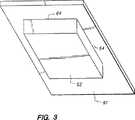
【0030】
電流コレクタ61および電極62の斜視図を図3に示す。共通境界64をよりよく示すために、電解質溜め63を除いてある。この実施態様において、共通境界64は、4本の線を含み、これらは、互いに、長方形の形状を形成する。
【0031】
好ましくは、電流コレクタ61は、電極62のシート抵抗の1/2未満であるシート抵抗を有する。さらに好ましくは、電流コレクタ61は、約50,000オーム/平方未満のシート抵抗を有し、なおさらに好ましくは、約1000オーム/平方未満のシート抵抗、最も好ましくは、約10オーム/平方未満のシート抵抗を有する。電流コレクタ61は、金属性またはカーボン箔(例えば、銀、ステンレススチール、白金またはグラファイト)であってもよく、または、導電性充填材、例えば、炭素繊維、カーボン粒子または金属粒子を負荷された高分子フィルムであってもよい。最も好ましくは、電流コレクタ61は、電気的に導電性のトレース;または、金属および/またはカーボン導電性充填材を含有する接着性高分子結合剤によって構成される電気的に導電性の接着剤の形である。接着剤は、接点および電極間の良好な電気的連続性を維持するために、接点68と電極62とを接着する。
【0032】
カソード電極62の表面で還元反応が進行すると、共通境界64,64’において塩化銀の還元が初期的に生じ、金属性銀を生成し、共通境界64,64’に近い領域をさらに電気的に導電性とする。装置を作動させるにつれ、塩化銀の還元が進行し、最終的に、カソード電極62の外側表面全体を覆う。
【0033】
共通境界64,64’においては、電流コレクタ61が電子の容易な供給を生じ、電解質溜め63内の液体がイオンを移動させるために利用可能であり、電解質溜め63と患者の体表面との間のイオン流によって構成される電気伝達流を生じさせるので、迅速に還元される。例えば、電極62が塩化銀を含む時、塩化銀は、還元され、Ag金属およびクロライドイオンを生成する。電解質溜め63内のアニオンは、体表面に移動し、薬剤を供給または採取するための電流を達成する。薬剤は、塩化銀が共通境界64,64’に沿って全て迅速かつふんだんに還元されるので、カソードにおいて著しい電圧降下または遅れ時間を生ずることなくコンプライアントな供給速度で皮膚を通して供給または採取される。
【0034】
対照的に、図1に示したように、従来技術の電極アセンブリ50は、電流コレクタ51および電解質溜め53と共通境界をわかたない電極52を有する。塩化銀電極52と電解質溜め53との間の界面56は、塩化銀電極52が実質的に非導電性であるので、電子を容易に供給しない。かくして、電極52は、電流コレクタ51によって生ずる電子を電解質溜め53と電極52との間の境界56に到達させないように実質的に絶縁し、かくして、電極52の界面56における塩化銀の還元を妨げる。かくして、電気抵抗における増大の正味効果は、回路のコンプライアンス電圧がコンプライアントな薬剤供給を初期的に達成するのに不十分であるかもしれないことである。
【0035】
電極アセンブリ60がアノード電極アセンブリである場合には、電極62は、電気化学的に酸化可能な材料、例えば、ポリアニリンによって構成されるアノードである。電解質溜め63は、典型的には、液体電解質を含有する高分子ゲルの形である。電極アセンブリ60がドナー電極アセンブリである場合には、ゲル内の液体電解質は、典型的には、薬剤溶液である。電極アセンブリ60が対向電極アセンブリである場合には、ゲル内の液体電解質は、典型的には、塩水である。
【0036】
アノードポリアニリン(ロイコ形)電極62の表面において、酸化反応が進行するにつれ、ポリアニリンの酸化が初期的に共通境界64,64’において生じ、酸化されたポリアニリン(ポリアニリンの還元されたロイコ形よりもさらに電気導電性であるエマラルジン形)を生成し、共通境界64,64’に近い領域をさらに電気導電性とする。装置が作動すると、ポリアニリンの酸化が進行し、最終的には、アノード電極62の外側表面全体を覆う。
【0037】
共通境界64,64’においては、電極62は、電流コレクタ61が電子の用意をし、電解質溜め63の液体がイオンを移動させるのに利用可能であり、電解質溜め63と患者の体表面との間のイオン流を構成する電気伝達流を生じさせるので、迅速に酸化される。例えば、電極62がロイコ−ポリアニリンを含む時、ロイコ−ポリアニリンは、酸化され、電気的に導電性の酸化されたポリアニリンを生成する。電解質溜め63内のカチオンは、体表面に移動し、薬剤を供給または採取するための電流を達成する。薬剤は、ポリアニリンが共通境界64,64’に沿って全て迅速かつふんだんに酸化されるので、アノードにおいて著しい電圧降下または遅れ時間を生ずることなくコンプライアントな供給速度で皮膚を通して供給または採取される。
【0038】
対照的に、図1に示したように、従来技術の電極アセンブリ50は、電流コレクタ51および電解質溜め53と共通境界をわかたない電極52を有する。例えば、ロイコ−ポリアニリン電極52と電解質溜め53との間の界面56は、ポリアニリン電極52が初期に(すなわち、著しい酸化が生ずる前)実質的に非導電性であるので、電子を容易に排出しない。かくして、電極52は、電流コレクタ51を電解質溜め53と電極52との間の境界56から実質的に絶縁し、かくして、電極52の界面56におけるロイコ−ポリアニリンの酸化を妨げる。かくして、電気抵抗における増大の正味効果は、回路のコンプライアンス電圧が所望されるかまたは必要とされる治療電流を供給するのに不十分であるかもしれないことである。
【0039】
電流コレクタ61、電極62および電解質溜め63の間の共通境界は、少なくとも1つの共通境界が存在する限り、また、共通境界が電極62の許容不能に高い初期電気抵抗を電極アセンブリ60について全体として許容可能な初期抵抗まで低下させるのに十分な長さを有する限り、いかなる形状または構成を有してもよい。例えば、電極62は、電流コレクタ61からオフセットすることができ、単一の共通境界(64または64’)を形成する。これとは別に、共通境界は、少なくとも1つの共通境界が存在する限り、円形、三角形、楕円形またはいずれのその他の形状(個別的にまたは集合的に)であってもよい。あるいは、電極62は、電解質溜め63を電流コレクタ61に直接接触させることのできるいずれの形状の孔またはスロット(例えば、ドーナツ形の電極)を有することもできる。
【0040】
若干の例においては、電極62および/または電流コレクタ61の接着力または親水性を改良するために、電極62と電流コレクタ61との間の接着力を改良するか、または、これら素子の電解質溜め63に対する接着力を改良するために、電極62および/または電流コレクタ61を接着剤または親水性表面塗膜のような材料の薄い層で被覆することが望ましいかもしれない。電極62および/または電流コレクタ61上の親水性表面塗膜は、また、これら素子のいずれかまたは双方と(例えば、水性)電解質溜め63との間の表面相互作用を改良するために使用することができる。このような塗膜は、電極62および/または電流コレクタ61を電解質溜め63から物理的に仕切る作用をする。しかし、電極62および/または電流コレクタ61上のいずれかのこのような塗膜が薄く、電気的にまたはイオン的に導電性である限り、その塗膜は、存在するであろう共通境界に対して障害ではなく被覆のためだと考えるべきである。
【0041】
共通境界の最小必要長さは、電源によって印加することのできる最高電圧;電気伝達流の処方されたレベル;および、電極62の初期シート抵抗等多数の因子に依存する。概して、被服の下に邪魔にならないように身につけるのに適合した小さな電気伝達経皮供給および採取装置は、約20ボルト未満の範囲の最高電圧、さらに典型的には、約2〜10ボルトの範囲の最高電圧を有する電源を有するであろう。さらに、このような装置は、典型的には、1mA未満、さらに典型的には、0.5mA未満の電気伝達流を印加する。さらに、粒子形態でレドックス種を含有する高分子成分(例えば、塩化銀粒子を含有するポリイソブチレンマトリックス)によって形成される電極は、典型的には、約1,000オーム/平方より大きな、さらに典型的には、約10,000オーム/平方より大きな電気シート抵抗を有するであろう。このような“典型的な条件”下では、共通境界の長さは、少なくとも約0.1cm、好ましくは、少なくとも約1cmである必要がある。共通境界長さ(l)対印加された電気伝達流(i)の比の関係で表すと、その比は、少なくとも0.1cm/mAである必要があり、好ましくは、少なくとも約1cm/mAである。
【0042】
本発明の電極アセンブリ70のもう1つの例を図5に示す。この構成において、電極62と電流コレクタ61との面する側は、同一の表面積を有し、互いに積層されて2層ラミネート構造を形成する。その結果、共通境界64は、電極62/電流コレクタ61ラミネートのエッジ上にある。
【0043】
本発明の電極アセンブリ80のもう1つの例を図6に示す。この構成においては、電極62は、電流コレクタ61より広い。その結果、共通境界64は、電極の“張り出し”の下側にある。
【0044】
本発明の電極アセンブリ90のもう1つの例を図7に示す。この構成においては、複数の電極62がその間に空間を有して電流コレクタ61に積層されている。電解質溜め63は、電流コレクタ61と接触して、複数の共通境界64を形成する。十分な長さの共通境界が存在する限り、その他の構成も本発明によって考えられる。図2〜図7を通して示した構成は、単なる例示である。
【0045】
概して、電極62は、初期において、非常に抵抗性の状態であるが、酸化または還元されると、より低い抵抗性となる材料を含む。カソード電極62の場合、電極は、少なくとも一部、電気的に還元可能な材料によって構成される。還元可能な材料は、金属化合物、金属錯体、内位添加化合物、アルカリ金属をホストするカーボン内位添加ホスト、および、電気的に酸化可能かまたは還元可能なポリマー類から選択することができる。還元可能な材料の特に好ましい類は、式:MX〔式中、Mは、電気的に還元されうる(アルカリ土類金属以外の)金属であり、Xは、高分子アニオン類;および、低分子量アニオン類、例えば、ハライド類、サルフェート類およびホスフェート類から選択されるが、好ましくは、ハライドである。〕によって定義される化合物である。最も好ましくは、Xは、クロライドである。好ましくは、Mは、銀、亜鉛または銅であり、さらに好ましくは、銀である。本発明のカソードに使用される最も好ましい電気化学的に還元可能な材料は、実質的に純粋な塩化銀である。
【0046】
本発明のカソードに使用される還元可能な材料のもう1つのタイプは、アルカリ金属タングステートのような内位添加化合物である。アルカリ金属タングステートについて示される還元反応は、以下の通りである:
M++MxWO3+e-→M1+xWO3
〔式中、Mは、アルカリ金属、好ましくは、ナトリウムである。〕
その他の還元可能なおよび酸化可能な種は、CRC Handbook of Chemistry and Physics, 57th Edition, D−141 to D−146に列挙されており、この文献は、参考とすることによって、本明細書に組込む。
【0047】
本発明のアノードに使用される好ましい電気化学的に酸化可能な材料は、ポリアニリンのロイコ形である。
本明細書で使用する“薬剤(agent)”という用語は、例えば、診断目的のために、体から採取される薬剤;および、治療的効果を達成するために、装置から体に供給される治療剤の両薬剤を含む。診断目的のための採取薬剤のコンテキストにおいて、薬剤は、例えば、血中グルコースの測定のような診断試験を行うために採取されるグルコースまたは電解質を含むいずれかの体分析物であってもよい。治療剤供給のコンテキストにおいては、“薬剤(agent)”という用語は、“医薬物質(drug)”と互換的に使用され、各々、生きている生物に供給する時に、所望される、通常、有益な効果を生ずる治療学的に活性な物質として、当分野において、その最も広い妥当な解釈を与えられることを意図する。例えば、“薬剤(agent)”とは、全ての治療カテゴリーからの治療化合物および分子を含み、例えば、抗感染症剤(例えば、抗生物質および抗ウイルス剤)、鎮痛剤(例えば、フェンタニール、スフェンタニル、ビュプレノルフィンおよび鎮痛剤の組合せ)、麻酔薬、抗関節炎剤、抗ぜん息剤(例えば、テルブタリン)、抗痙攣薬、抗うつ病剤、抗糖尿病剤、下痢止め剤、抗ヒスタミン剤、抗炎症剤、抗片頭痛剤、抗乗り物酔い製剤(例えば、スコポルアミンおよびオンダンセトロン)、抗腫瘍剤、抗パ−キンソン病剤、かゆみ止め薬、抗精神病薬、解熱剤、鎮痙薬(胃腸および尿を含む)、抗コリン作働薬、交感神経様作用剤、キサンチンおよびその誘導体、心臓血管製剤(カルシウムチャンネルブロッカー、例えば、ニフェジピンを含む)、β−アゴニスト(例えば、ドブタミンおよびリトドリン)、β−ブロッカー、抗不整脈剤、抗高血圧症薬(例えば、アテノロール)、ACE阻害剤(例えば、リジノプリル)、利尿薬、血管拡張薬(全身、心臓、末梢および大脳を含む)、中枢神経系刺激剤、咳きおよび悪寒止め製剤、うっ血除去剤、診断薬、ホルモン類(例えば、上皮小体ホルモン類)、催眠剤、免疫抑制剤、筋肉弛緩剤、副交感神経遮断剤、副交感神経作働剤、プロスタグランジン類、蛋白質類、ペプチド類、精神刺激薬、鎮静薬および精神安定薬が挙げられるが、これらに限定するものではない。
【0048】
本発明の電気伝達装置は、また、医薬物質および/または薬剤、例えば、バクロフェン、ベクロメタゾン、ベータメタゾン、ビュスピロン、クロモリンナトリウム、ジチアゼム、ドキサゾシン、ドロペリドール、エンケイニド、フェンタニール、ヒドロコルチゾン、インドメタシン、ケトプロフェン、リドケイン、メトトレキセート、メトクロプラミド、ミコナゾール、ミダゾラム、ニカルジピン、ピロキシカム、プラゾシン、スコポルアミン、スフェンタニル、テルブタリン、テストステロン、テトラケインおよびベラパミルを供給することもできる。
【0049】
本発明の電気伝達装置は、また、ペプチド類、ポリペプチド類、蛋白質類、オリゴヌクレオチド類、多糖類およびその他の巨大分子を供給することができる。このような分子は、それらの大きさにより、経皮的または経粘膜的に供給することが困難であることが当分野において知られている。例えば、このような分子は、300−40,000ドルトンの範囲の分子量を有することができ、例えば、LHRHおよびその類縁体(例えば、ブセレリン、ゴセレリン、ゴナドレリン、ナフレリンおよびロイプロリド)、GHRH、GHRF、インスリン、インスリノトロピン、ヘパリン、カルシトニン、オクトレオチド、エンドルフィン、TRH、NT−36またはN−〔〔(S)−4−オキソ−2−アゼチジニル〕カルボニル〕L−ヒスチジル−L−プロリンアミド〕、リプレシン、下垂体ホルモン(例えば、HGH、HMG、HCG、デスモプレッシンアセテート)、フォリサイルルテオイド、a−ANF、成長因子放出因子(GFRF)、b−MSH、ソマトスタチン、ブレディキニン、ソマトトロピン、血小板誘導成長因子、アスパラギナーゼ、ブレオマイシンサルフェート、キモパパイン、コレシストキニン、コリオニックゴナドトロピン、コルチコトロピン(ACTH)、エリスロポイエチン、エポプレステノール(血小板凝血阻害剤)、グルカゴン、ヒルログ、ヒアルロニダーゼ、インターフェロン、インターロイキン−2、メノトロピン類(例えば、ウロフォリトロピン(FSH)およびLH)、オキシトシン、ストレプトキナーゼ、組織プラスミノゲン活性剤、ウロキナーゼ、バソプレッシン、デスモプレッシン、ACTH類縁体、ANP、ANPクリアランス阻害剤、アンギオテンシンIIアンタゴニスト、抗利尿ホルモンアゴニスト、抗利尿ホルモンアンタゴニスト、ブラディキニンアンタゴニスト、CD4、セレダーゼ、CSF’s、エンケファリン類、FABフラグメント、IgEペプチド抑制剤、IGF−1、神経栄養因子、コロニー刺激因子、上皮小体ホルモンおよびアゴニスト、上皮小体ホルモンアンタゴニスト、プロスタグランジンアンタゴニスト、ペンチゲチド、蛋白質C、蛋白質S、レニン阻害剤、チモシンα−1アンチトリプシン(組換型)およびTGF−βが挙げられるが、これらに限定するものではない。
【0050】
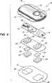
図4は、本発明に関して使用することのできる典型的な電気伝達供給装置を示す。装置10は、上方ハウジング16、回路基板アセンブリ18、下方ハウジング20、電極42および42’、電解質ゲル溜め26および28、および、皮膚相溶性の接着剤30を含む。上方ハウジング16は、患者の皮膚上に装置10を保持する助けをする横方向のウイング15を有する。上方ハウジング16は、好ましくは、射出成形可能なエラストマー(例えば、エチレンビニルアセテート)によって構成される。印刷された回路基板アセンブリ18は、1個以上の電気的構成部材19(例えば、集積回路)および電池32を含む。回路基板アセンブリ18は、開口13aおよび13bを通してポスト(図4には図示せず)によってハウジング16に取りつけられ、ポストの終端は、回路基板アセンブリ18をハウジング16にヒートステイクする(heat stake)ために、加熱/溶融される。下方ハウジング20は、接着剤30によって上方ハウジング16に取りつけられ、接着剤30の皮膚遠位側は、下方ハウジング20と、ウイング15の底部表面を含む上方ハウジング16とに接着する。
【0051】
回路基板アセンブリ18のアウトプット(図4には図示せず)は、それぞれ、電流コレクタ22および24を通して電極42’および42と電気的な接触をする。電流コレクタ22および24は、それぞれ、電極42’および42の皮膚遠位側と接着する電気的に導電性の接着剤によって構成される。電流コレクタ22および24の皮膚遠位側は、下方ハウジング20に形成された開口23’および23を通して回路基板アセンブリ18の下側で回路アウトプットと接着する。電極42および42’は、同様に、電解質ゲル溜め26,28の皮膚遠位側と直接機械的および電気的に接触される。電解質ゲル溜め26,28の皮膚近位側は、接着剤の開口29’および29を通して患者の皮膚と接触する。
【0052】
装置10は、所望により、患者が電気伝達によって一服の薬を自分で服用可能にするという特徴を有する。プッシュボタンスイッチ12を押すと、回路基板アセンブリ18上の電子回路が予め決められた長さの供給間隔で、電極/電解質溜め42’,42および26,28に予め決められたDC電流を供給する。プッシュボタンスイッチ12は、便利なように、装置10の頂部側に位置し、被服を介して容易に操作される。プッシュボタンスイッチ12を短時間、例えば、3秒以内に2回押すと、好ましくは、薬剤供給について装置10を活性化するために使用することができ、それによって、装置10の不注意による作働の可能性を最小とする。好ましくは、装置は、LED14を点灯させ、および/または、例えば、“ビーパー”から聴取可能な信号により、薬剤供給間隔の開始の目視可能および/または聴取可能な確認をユーザーに伝える。薬剤は、予め決められた供給間隔にわたって、例えば、腕上で電気伝達により、患者の皮膚を通して供給される。
【0053】
本発明に従えば、電極42および42’は、それぞれ、電解質ゲル溜め28および26の皮膚遠位側に押しつけて置かれる。これらくぼみの深さは、電極42および42’の厚さにほぼ等しいので、装置10の2電極アセンブリの各々には卵形形状の共通境界が存在する。かくして、電流コレクタ22、電極42’および電解質ゲル溜め26の間には共通境界が存在する。また、電流コレクタ24、電極42および電解質ゲル溜め28の間にも共通境界が存在する。装置10は、装置10の両側(すなわち、アノード側およびカソード側)の共通境界を示すが、本発明の範囲内において、電気伝達装置10の一方の側のみ(すなわち、アノード側またはカソード側)のみに、共通境界を使用することもできる。
【0054】
プッシュボタンスイッチ12、回路基板アセンブリ18上の電子回路および電池32は、上方ハウジング16と下方ハウジング20との間に接着剤により“密封される(sealed)”。上方ハウジング16は、好ましくは、ゴムまたはその他のエラストマー材料によって構成される。下方ハウジング20は、好ましくは、くぼみ25,25’を形成するために容易に成形することができ、開口23,23’を形成するために切断することのできるプラスチックまたはエラストマーシート材料(例えば、ポリエチレンまたはポリエチレンテレフタレートコポリマー)によって構成することができる。組み立てた装置10は、好ましくは、耐水性(すなわち、スプラッシプルーフ)であり、最も好ましくは、防水性である。システムは、容易に体に合うように浅い彫りを有し、それによって、着用部位およびその周りで自由に運動することができる。電解質ゲル溜め26および28は、装置の皮膚接触側に位置し、正常な取り扱いおよび使用の間の偶発的な電気ショートを防止するために、十分に仕切られている。
【0055】
装置10は、周辺(電解質ゲル溜め26および28の周囲を取り囲む)接着剤30によって体表面(例えば、皮膚)に接着する。接着剤30は、正常なユーザーの活動の間、装置10を体の位置に留め、予め決められた着用期間(例えば、24時間)後、無理なく取り外し可能なような接着特性を有する。
【0056】
電解質ゲル溜め26および28は、各々、ゲルマトリックスに含有される液体電解質を含む。装置10が経皮薬剤供給装置である場合には、ゲル溜め26および28の少なくとも一方は、薬剤溶液または懸濁液を収容する。ほぼ1×10-4M〜1.0M以上の範囲の薬剤濃度を使用することができるが、この範囲の低い部分の薬剤濃度が好ましい。ゲルマトリックスについての適したポリマーは、本質的に、いずれかの非イオン性合成および/または天然産の高分子材料を含む。活性剤が極性および/またはイオン化可能である時、薬剤の溶解度を高めるので、極性であることが好ましい。所望により、ゲルマトリックスは、水膨潤可能であろう。適した合成ポリマーの例としては、ポリ(アクリルアミド)、ポリ(2−ヒドロキシエチルアクリレート)、ポリ(2−ヒドロキシプロピルアクリレート)、ポリ(N−ビニル−2−ピロリドン)、ポリ(n−メチロールアクリルアミド)、ポリ(ジアセトンアクリルアミド)、ポリ(2−ヒドロキシエチルメタクリレート)、ポリ(ビニルアルコール)およびポリ(アリルアルコール)が挙げられるが、これらに限定するものではない。ヒドロキシル官能性縮合ポリマー(すなわち、ポリエステル類、ポリカーボネート類、ポリウレタン類)もまた適した極性合成ポリマーの例である。ゲルマトリックスとして使用するのに適した極性天然産のポリマー類(またはそれらの誘導体)の例としては、セルロースエーテル類、メチルセルロースエーテル類、セルロースおよびヒドロキシル化されたセルロース、メチルセルロースおよびヒドロキシル化されたメチルセルロース、ガム類、例えば、グアー、ローカスト、カラヤ、キサンタン、ゼラチン、および、それらの誘導体が挙げられる。イオン性ポリマーもマトリックスに使用することができるが、ただし、利用可能な対イオンは、薬剤イオン類であるか;または、活性剤に関して反対に帯電したその他のイオン類である。
【0057】
本発明を、その好ましい具体的な実施態様に関連して説明したが、前述の説明およびそれに従う例は、本発明の例を示すことを意図し、何ら本発明を限定するものではないことを理解するべきである。本発明の範囲に入るその他の態様、利点および変形変更は、当業者であれば、明らかであろう。
【0058】
比較実施例 1
(1)塩化銀カソードを使用するが、共通境界条件を使用しない図1に従う従来技術のカソード電極アセンブリと;(2)やはり、塩化銀カソードを使用し、電流コレクタ、電極および液体電解質の間の共通境界を使用する本発明の図2および図3に従うカソード電極アセンブリとの間の比較を図8に示す。
【0059】
従来技術のカソード電極アセンブリ(カソードA)は、シート抵抗10オーム/平方を有する電気的に導電性の接着剤からなる電流コレクタに積層された塩化銀箔カソードを含んでいた。箔は、面積2.85cm2を有し、液体電解質は、塩水含有ゲルであった。カソードAにおいて、ゲルは、塩化銀箔と接触させて置いたが、導電性接着剤とは接触させなかった。かくして、本発明に従う共通境界は存在しなかった。ゲル/箔接触面積は、2.0cm2であった。
【0060】
本発明のカソード電極アセンブリ(カソードB)は、やはり、シート抵抗10オーム/平方を有する電気的に導電性の接着剤に積層された塩化銀箔カソードを含んでいた。箔は、面積1cm2を有する円板であり、接着剤は、面積2.85cm2を有した。したがって、ゲル/電極接触面積は、1.0cm2であり、共通境界の長さは、電極の周長と等しく;3.54cmであった。従来技術のカソードは、0.05mm(0.002インチ)厚さのAgClストリップであった。カソードBは、カソードAより小さな塩化銀箔(すなわち、1.0cm2)を有した。
【0061】
塩化銀箔は、Engelhard−CLAL of Cartret, New Jerseyによって供給されている塩化銀ストリップから作成した。塩化銀ストリップは、厚さ0.051mm(0.002インチ)を有し、切断し、電気的に導電性の接着剤片に積層した。
【0062】
両カソード電極例についての電池アセンブリにおいて、液体電解質/ゲル配合物は、15%のポリビニルアルコール(PVOH)、2%のヒドロキシプロピルメチルセルロース(HPMC)、0.1MのNaCl、および、残り脱イオン水の約10mlであった。塩水の初期pHは、6.26であった。
【0063】
両電極アセンブリを同一の電流密度0.3mA/cm2下で放電させた(カソードAは、カソードB(1cm2)よりも大きな表面積(2cm2)を有するので、カソードAについての放電電流(0.6mA)は、対応して、カソードBについての放電電流(0.3mA)よりも高かった。)。放電は、カソード電極アセンブリをガルバノスタット(galvanostat)の陰極に電気的に接続することによって行った。銀箔アノードは、ガルバノスタットの陽極に電気的に接続し、ゲルの自由表面に対して置いた。放電の間、カソードAおよびBの電圧をAg/AgCl準参照電極に対して測定した。
【0064】
図8に示したように、カソードの放電挙動は、放電の初期の間、著しく異なる(すなわち、遅れ時間)。図8に見られるように、従来技術のカソード(カソードA)は、5.68Vの初期放電電圧(すなわち、始動電圧)を有したが、他方、本発明のカソード(カソードB)は、始動電圧0.21Vのみを有した。これら実験において、遅れ時間は、0.30V以下に低下するために、ガルバノスタットによって印加される電圧に要求される時間と定義した。カソードAについての遅れ時間は、7.1分であり、他方、カソードBについての遅れ時間は、9秒のみであった。
【0065】
さらなる実験を、上記したように、3つの従来技術カソードおよび3つの本発明のカソードについて試験した。従来技術カソードについての平均始動電圧は、3.71Vであり、他方、本発明の3つのカソードについての平均始動電圧は、0.41Vであった。従来技術カソードについての平均遅れ時間は、9.8分であり、他方、本発明の3つのカソードについての平均遅れ時間は、わずか8.6秒であった。
【0066】
電気伝達システムまたはほとんどのいずれかの医用装置において、低い始動電圧および性能が改良され、低い電力消費を生ずる遅れ時間を有することは非常に好ましい。つまり、本発明の性能は、従来技術カソードよりも予想しえなかったほど優れている。
【0067】
比較実施例 2
装置の各々が、電源;一方がアノードであり、他方がカソードである、1対の電極アセンブリを有する2つの電気伝達装置(装置Aおよび装置B)を組み立てる。各電極アセンブリは、銅箔電流コレクタ;電極;および、塩水を収容するポリビニルアルコールゲル溜めを含む。各装置のカソード電極アセンブリは、塩化銀カソードを含み、図1に示した構成を有し、すなわち、いずれの装置のカソード電極アセンブリにおいても共通境界条件が存在しない。装置Aのアノード電極アセンブリは、ロイコポリアニリンストリップによって構成され、図1に示した構成を有し、すなわち、装置Aのアノード電極アセンブリにおいては、共通境界条件が存在しない。他方、装置Bのアノード電極アセンブリは、ロイコポリアニリンストリップによって構成され、図2に示した構成を有し、すなわち、装置Bのアノード電極アセンブリにおいては、共通境界条件が存在する。0.5mAの電気伝達流を印加するガルバノスタットに各装置の電極アセンブリを接続する。共通境界条件ロイコポリアニリンアノードを有する装置Bの始動電圧は、ロイコポリアニリンアノード電極アセンブリを有するが共通境界条件を有しない装置Aの始動電圧よりも有意に低い。さらに、アウトプット電圧0.3Vに到達するためのガルバノスタット電源についての遅れ時間は、装置Aと比較して、装置Bで有意に短い。
【0068】
かくして、我々の発明をおおよそ説明し、ある種の好ましい実施態様を詳細に説明したので、本発明についての種々の変形変更は、当業者であれば、本発明の範囲から逸脱することなくなすことができ、特許請求の範囲の請求項によってのみ限定されることが容易に明らかであろう。
【図面の簡単な説明】
【図1】 図1は、電気伝達電極アセンブリの従来技術の構成の断面図である。
【図2】 図2は、本発明の電気伝達電極アセンブリの例としての構成の断面図である。
【図3】 図3は、本発明の電流コレクタおよび電極の底面斜視図である。
【図4】 図4は、本発明の例としての電気伝達装置の分解斜視図である。
【図5】 図5は、本発明の電極アセンブリの断面図である。
【図6】 図6は、本発明のもう1つの電極アセンブリの断面図である。
【図7】 図7は、本発明のなおもう1つの電極アセンブリの断面図である。
【図8】 図8は、本発明のカソード電極アセンブリの電気伝達装置始動の間の遅れ時間の短縮を示すカソード電圧対時間のグラフである。[0001]
Technical field
The present invention generally provides for transdermal or transmucosal delivery of a beneficial agent (eg, a pharmaceutical substance) to a patient, or transdermal or transmucosal collection of a body analyte (eg, glucose) from a patient. The present invention relates to an electric transmission device. Most particularly, the present invention is an electrode configured to have improved electrical performance, for example, low electrical resistance at device start-up and the short time required to reach a prescribed transdermal drug flux. Concerning assembly.
[0002]
Background art
As used herein, “electrotransport” generally refers to a membrane (eg, skin, mucous membrane or nail) in which supply is at least partially electrically induced or assisted by the application of an electrical potential. The supply of at least one drug or medicinal substance (charged, uncharged or mixtures thereof) through. As used herein, the terms “drug” and “agent” are used interchangeably and provide the desired, usually beneficial, effect when delivered to a living organism. It is intended to include any resulting therapeutically active substance. For example, a beneficial therapeutic agent can be introduced into the patient's systemic circulation by means of electrical transmission through the skin.
[0003]
The electrotransfer process has been found useful for transdermal administration of drugs such as lidocaine, hydrocortisone, fluoride, penicillin, dexamethasone; and many other drugs. A common use of the electrical transmission system is to diagnose cystic fibrosis by supplying pilocarpine iontophoretically. Pilocarpine stimulates sweat production. The sweat is then collected and analyzed for its chloride content to detect the presence of the disease. More recently, “reversible” electrical transfer methods have been used to transcutaneously extract body analytes, such as glucose, to measure blood glucose levels. For a description of reversible iontophoresis devices and methods for analyte collection, see Guy et al. U.S. Pat. No. 5,362,307.
[0004]
Electrical transmission devices generally use two electrodes, each positioned in intimate contact with a portion of the patient's body (eg, skin). For drug delivery, an active or donor electrode delivers a therapeutic agent (eg, a pharmaceutical substance) into the body. The counter or return electrode closes the electrical circuit by a donor electrode that passes through the patient's body. An electrical energy source, such as a battery, supplies current to the body through the electrodes. For example, if the therapeutic agent to be delivered into the body is positively charged (ie, cationic), the anode is the donor electrode and the cathode is the counter electrode that completes the circuit. If the therapeutic agent to be delivered is negatively charged (ie anionic), the cathode is the donor electrode and the anode is the counter electrode. The drug delivery rate is generally proportional to the applied electrical transfer flow. For this reason, commonly used electrical transmission systems use electrical circuits that regulate the current applied by such devices. In order to extract a body analyte, an active or collecting electrode extracts body analyte from the body. The counter or return electrode closes the electrical circuit with an active electrode through the patient's body. If the body analyte to be extracted from the body is cationic, the cathode is the active electrode and the anode is the counter electrode that completes the circuit. When the body analyte to be extracted is anionic, the anode is the active electrode and the cathode is the counter electrode. In the case of glucose extraction, since glucose is an uncharged molecule, either or both of the anode and the cathode can be the active electrode. Therefore, glucose is extracted to both electrodes at a relatively same rate by the electroosmosis phenomenon.
[0005]
A widely used electrical transfer process, iontophoresis (also referred to as electromigration), involves the electrically induced transfer of charged ions. Also referred to as osmosis, which involves the transdermal flow of a liquid solvent containing a drug that is supplied or collected (charged or non-ionic) under the influence of an applied electric field. The electrical transfer process, also referred to as electroporation, includes forming pores that are temporarily present in a biofilm (eg, skin) by applying high voltage pulses thereto. In some electrical transmission systems, more than one of these processes may occur to some degree simultaneously.
[0006]
Most transcutaneous electrical transmission devices have an anode electrode assembly and a cathode electrode assembly, each electrode assembly being in ion permeable relationship with an ionic conductive liquid reservoir placed in contact with the patient's skin in use. It is constituted by an electrically conductive electrode. Gel reservoirs such as those described in Webster US Pat. No. 4,383,529 are a preferred form of reservoir because hydrated gels are easier to handle and manufacture than liquid-filled containers. Water is partly water soluble in many pharmaceutical salts, and partly water has excellent biocompatibility and is between the hydrogel reservoir and the skin that is acceptable from an irritant standpoint. Is a highly preferred liquid solvent used in such reservoirs.
[0007]
There are generally two types of electrodes used in transcutaneous electrical transmission devices; those made from materials that are not electrochemically reactive; and those made from materials that are electrochemically reactive. There is something. Electrodes that are not electrochemically reactive, such as stainless steel, platinum and carbon based electrodes, tend to promote the electrochemical oxidation or reduction of liquid solvents at the electrode / reservoir interface. When the solvent is water, the oxidation reaction (at the anode electrode surface) produces hydronium ions, while the reduction reaction (at the cathode interface) produces hydroxyl ions. Thus, one significant drawback in using electrochemically non-reactive electrodes is that pH changes occur during device operation due to water oxidation and reduction reactions occurring at the electrode / reservoir interface. The oxidation and reduction of water is described in Phipps et al. Can be largely avoided by using electrochemically reactive electrodes, as discussed in U.S. Pat. No. 4,747,819. Preferred electrochemically oxidizable materials used for the anode electrode include metals such as silver, copper and zinc. Of these, silver is most preferred because silver is more biocompatible than most other metals. Preferred electrochemically reducible materials used for the cathode electrode include metal halides. Of these, silver halide such as silver chloride is most preferred. While these electrode materials provide an elegant solution to the pH drift problem in electrical transfer reservoirs, they have a series of problems inherent to them. For example, a silver anode is oxidized to produce silver ions (Ag → Ag++ E-). Silver cations are supplied to the patient's skin by iontophoresis from the anode, where they produce a gray or black discoloration as soon as the skin is exposed to sunlight. Attempts have been made to limit the electromigration of electrochemically generated silver ions from the anode electrode. In order to react with electrochemically generated silver ions to produce substantially insoluble silver halide, thereby generating halide ions that prevent migration of silver ions to the skin. Disclose the use of halide drug salts in the anode reservoir, see, for example, Hopps et al. U.S. Pat. No. 4,747,819 and Phipps et al. See WO 96/39224. In order to react with electrochemically generated silver ions to produce substantially insoluble silver halide, thereby generating halide ions that prevent migration of silver ions to the skin. Discloses the use of a halide resin in the anode reservoir, see also, eg, Hopps et al. See WO95 / 27530. Unfortunately, both of these approaches to prevent silver ion migration to the skin have their own drawbacks. Hopps et al. U.S. Pat. No. 4,747,819 and Phipps et al. For the first approach described in WO 96/39224, a very large or "excess" amount is required to generate enough halide ions to prevent silver migration, particularly over a long period of drug delivery. It may be necessary to load the halide drug salt into the anode reservoir. This is disadvantageous because many drugs are expensive and thereby costly to solve the silver migration problem. Hopps et al. For the second approach described in WO 95/27530, it has been found that halide resins contain many impurities and unreacted monomer components that cannot be efficiently removed from the resins. Some of these components are likely to cause unwanted skin irritation when the resin is used in an electrical reservoir because the impurities are supplied to the skin percutaneously by the applied electrical flow. Has been issued.
[0008]
One important solution to the migration problem of metal ions encountered at oxidizable metal anodes is described in Phipps et al. US Pat. Nos. 4,747,819 and 5,573,503, the use of intercalated compounds. Although the use of intercalating compounds avoids the problem of migration of metal ions into the patient's skin, at least some of these materials (eg, polyanilines) are partly in their very high initial (ie, When the electrical transmission device begins to apply the electrical transmission flow), it is not widely used due to electrical resistance. The problem of high electrical resistance is discussed in further detail below with respect to prior art silver halide cathodes.
[0009]
Thus, (1) the generation of competitive metal ions found in anodes formed of conventional oxidizable metals; and / or (2) the need for an improved anode electrode that does not have the problem of high initial electrical resistance. Exists.
[0010]
On the cathode side, silver halide cathodes produce only halides (eg, chloride) when they are electrochemically reduced (AgX → Ag + X-). Electrochemically generated halide (eg, chloride) ions do not tend to be supplied to the patient from the cathode, but chloride is naturally present in the body in significant amounts and therefore chloride ions from the cathode. The supply will not adversely affect. Thus, while silver halide cathodes are extremely biocompatible, they are substantially non-conductive until at least sufficient silver halide has been reduced to form metallic silver. It has two serious drawbacks. This is equivalent to the problem of high initial electrical resistance found in anodes formed with intercalated compounds such as polyanilines, eg, anodes formed with polyaniline oxidize a sufficient amount of polyaniline. Until no significant amount of current is conducted. This is an electrical resistance to a relatively small voltage supplied by a small battery (eg, a coin cell battery) that is used to operate an electrical transmission device that a silver halide cathode and / or polyaniline anode attach to a small patient. Is too high, causing a delay in the start of operation of the compliant device. Of course, electrochemical reduction of silver halide to form metallic silver; and polyaniline to form a more conductive (ie, oxidized or emeraldine) form of polyaniline. The reduced (ie, leuco) form of electrochemical oxidation of the following reaction:
Anode polyaniline (PA) oxidation: PAleuco→ PAemaraldine+ 2H++ 2e-
Cathodic silver chloride reduction: AgCl + e-→ Ag + Cl-
And gradually occurs at the interface between the electrode and the liquid electrolyte.
Reduction of the leuco form of polyaniline is described in Cushman et al. , “Spectroelectrochemical Study of Polylineine: the Construction of a pH-Potential Phase Diagram”, Journal of Electrochemical 3 (1986), 1986, 3 of Chemistry 3 (3). Although the formation of metallic silver at the cathode / liquid electrolyte interface and the formation of oxidized polyaniline at the anode / liquid electrolyte interface gradually improves the electrical conductivity of the electrode, it is a rather gradual process. As a result, conventional electrode configurations such as that shown in FIG. 1 are undesirable due to their high electrical resistance at the beginning of operation of the electrical transmission device. The
[0011]
The electrical resistance of
[0012]
Of course, the delay in reaching the operation of a compliant electrical transmission device can be shortened by increasing the voltage of the battery, but this involves more (or even more) powering the device. (Expensive) battery is required, which increases the cost of supplying the electroconductive drug and is undesirable. The delay in reaching the operation of a compliant electrical transmission device is also described by Myers et al. US Pat. No. 5,147,297 also overcomes by adding electrically conductive fillers such as powdered metal or carbon to the internally doped anode or silver halide cathode. can do. However, this means that the conductive fillers must be of very good quality and have a uniform distribution throughout the electrode matrix, making these electrodes more difficult to manufacture and making the electrodes more expensive. To do.
[0013]
Thus, a significantly higher power supply voltage or other expensive conductivity to achieve compliant drug delivery quickly and without any significant voltage drop due to high initial voltage resistance, overcoming any significant initial electrode resistance There is a need for improved electrodes for electrical transmission devices that do not require fillers.
[0014]
Description of the invention
The present invention relates to the prior art electrode assembly shown in FIG. 1 in which the
[0015]
The electrode is at least partially constituted by an electrochemically reactive (ie, electrochemically oxidizable or reducible) constituted by a solid phase. The electrode has a high initial electrical sheet resistance, typically greater than about 100 ohms / square, which is lowered by exposing the electrode to electrical current. When exposed in this way, the electrochemically reactive material is oxidized or reduced to a form having a lower electrical resistance, and the sheet resistance of the electrode is lower than its initial sheet resistance.
[0016]
The current collector has a low initial resistance (ie, it is very conductive) and includes at least part of the electrical connection between the device power supply and the electrode. Thus, the current collector conducts current between the power source and the electrode.
[0017]
The electrode; current collector; and electrolyte reservoir form a common boundary when the electrical transfer device begins to apply an electrical transfer flow. The common boundary condition reduces the delay time to achieve a compliant current transfer supply and lower initial current resistance in the electrode assembly of the present invention, thereby allowing only lower power supply voltages to operate the device. do not need.
[0018]
The electrode assembly of the present invention comprises (1) an anode electrode assembly in which the electrode is composed of a resistive oxidizable material, for example, a leuco form of polyaniline; or (2) a resistive reducible material, for example, Any of the cathode electrode assemblies made of silver halide may be used.
[0019]
BEST MODE FOR CARRYING OUT THE INVENTION
Definition
As used herein, the term “electrochemically reactive material” refers to a compound or composition that can be oxidized or reduced electrochemically and is the reacted form (ie, oxidized) of the material. Or reduced form) has a lower electrical resistance than the unreacted form of the material (ie, the oxidizable or reducible form, respectively). The term also includes intercalated host materials, which themselves can be directly oxidized or reduced, or can be internally doped with a dopant that is oxidized or reduced.
[0020]
As used herein, the term “common boundary” means the macroscopic and measurable intersection of a current collector; an electrode; and an electrolyte reservoir.
[0021]
As used herein, the term “electrode assembly” includes at least the following three elements: a current collector; an electrode; and a collection of electrolyte reservoirs.
[0022]
As used herein, the term “electric sheet resistance” is the surface resistance between opposing edges of a unit square of material. The electrical sheet resistance (sometimes referred to as surface resistivity in the literature) is generally expressed in the literature as the symbol ρ.sAnd is used to characterize the current on the surface. The resistance across the square is independent of the dimensions of the square, and the unit of sheet resistance is ohms, or even more than necessary (and as used herein) ohms / square. The conductive surface is always a layer with a finite thickness t, and the sheet resistance is given by the following formula: ρs= Ρv÷ volume efficiency of the layer ρ by tvRelated to The sheet resistance of any given electrode or current conductor is the American Society for Testing and Materials (ASTM), West Conshohocken, PA, volume 10.0, 19 Standard Test 96, Test Standard Desd. It can be measured according to the method described in “Method for DC Resistance or Conduction of Moderately Conductive Methods”.
[0023]
As used herein, the term "body surface" includes living animal skin, mucous membranes and / or nails. In particular, it includes living human skin.
[0024]
As used herein, the term “electrolyte reservoir” means a liquid that contains or receives dissolved ions during device operation. This term includes aqueous salt solutions used for counter electrodes; and drug solutions or suspensions of donor electrodes. The term also includes polymers such as gels containing such solutions or suspensions, matrices such as sponges or fabrics. The term includes both aqueous and non-aqueous solutions (eg, solutions of electrolytes dissolved in glycols or glycerol).
[0025]
As used herein, the term “compliant agent delivery” means that the drug is delivered through the body surface in an electrical transmission flow prescribed via electrical transmission. There is no compliant drug supply when the device component and / or skin has so high electrical resistance that the electrical transmission device cannot deliver the prescribed electrical transmission flow even at the maximum applied voltage. .
[0026]
As used herein, the term “lag time” refers to the time during which an electrical transmission device applies a non-compliant current. In general, the delay time is measured from the time when the electrical transmission device begins to apply the electrical transmission flow to the time when the prescribed electrical transmission flow begins to be applied.
[0027]
FIG. 2 shows one example of an electrode assembly 60 according to the present invention. Similar to the prior
[0028]
Unlike prior art electrode assemblies, the electrode assembly 60 of the present invention uses
[0029]
If electrode assembly 60 is a cathode electrode assembly,
[0030]
A perspective view of the
[0031]
Preferably, the
[0032]
When the reduction reaction proceeds on the surface of the
[0033]
At the
[0034]
In contrast, as shown in FIG. 1, the prior
[0035]
When electrode assembly 60 is an anode electrode assembly,
[0036]
As the oxidation reaction proceeds on the surface of the anodic polyaniline (leuco-shaped)
[0037]
At the
[0038]
In contrast, as shown in FIG. 1, the prior
[0039]
The common boundary between the
[0040]
In some instances, to improve the adhesion or hydrophilicity of
[0041]
The minimum required length of the common boundary depends on a number of factors such as the highest voltage that can be applied by the power source; the prescribed level of electrical transfer current; and the initial sheet resistance of the
[0042]
Another example of an electrode assembly 70 of the present invention is shown in FIG. In this configuration, the
[0043]
Another example of an
[0044]
Another example of an
[0045]
In general,
[0046]
Another type of reducible material used in the cathode of the present invention is an intercalation compound such as alkali metal tungstate. The reduction reaction shown for alkali metal tungstates is as follows:
M++ MxWOThree+ E-→ M1 + xWOThree
[Wherein M is an alkali metal, preferably sodium. ]
Other reducible and oxidizable species are described in CRC Handbook of Chemistry and Physics, 57th Edition, D-141 to D-146, which is incorporated herein by reference.
[0047]
The preferred electrochemically oxidizable material used for the anode of the present invention is the leuco form of polyaniline.
As used herein, the term “agent” refers to an agent taken from the body, eg, for diagnostic purposes; and a treatment delivered to the body from a device to achieve a therapeutic effect. Includes both drugs. In the context of a collected drug for diagnostic purposes, the drug may be any body analyte that contains glucose or an electrolyte collected to perform a diagnostic test such as, for example, measurement of blood glucose. In the context of therapeutic agent delivery, the term “agent” is used interchangeably with “drug”, each of which is usually beneficial when delivered to a living organism. It is intended to be given the broadest reasonable interpretation in the art as a therapeutically active substance that produces a positive effect. For example, “agent” includes therapeutic compounds and molecules from all therapeutic categories, such as anti-infective agents (eg, antibiotics and antiviral agents), analgesics (eg, fentanyl, sufentanil). , A combination of buprenorphine and analgesics), anesthetics, anti-arthritic agents, anti-asthmatic agents (eg terbutaline), anticonvulsants, antidepressants, anti-diabetic agents, anti-diarrheal agents, anti-histamine agents, anti-inflammatory agents Anti-migraine agents, anti-motion sickness preparations (eg scopolamine and ondansetron), anti-tumor agents, anti-Parkinson's disease agents, anti-itch agents, antipsychotics, antipyretic agents, antispasmodics (including gastrointestinal and urine) , Anticholinergic drugs, sympathomimetic drugs, xanthine and its derivatives, cardiovascular preparations (calcium channel blockers, eg nifedipine ), Β-agonists (eg, dobutamine and ritodrine), β-blockers, antiarrhythmic agents, antihypertensive agents (eg, atenolol), ACE inhibitors (eg, lidinopril), diuretics, vasodilators (systemic, Heart, peripheral and cerebrum), central nervous system stimulants, cough and chill preparations, decongestants, diagnostics, hormones (eg parathyroid hormones), hypnotics, immunosuppressants, muscle relaxants Parasympathetic blockers, parasympathomimetic agents, prostaglandins, proteins, peptides, psychostimulants, sedatives and tranquilizers, but are not limited to these.
[0048]
The electrical transmission device of the present invention is also a pharmaceutical substance and / or drug, such as baclofen, beclomethasone, betamethasone, buspirone, cromolyn sodium, dithiazem, doxazosin, droperidol, encainide, fentanyl, hydrocortisone, indomethacin, ketoprofen, lidocaine, methotrexate , Metoclopramide, miconazole, midazolam, nicardipine, piroxicam, prazosin, scopolamine, sufentanil, terbutaline, testosterone, tetracaine and verapamil.
[0049]
The electrical transmission device of the present invention can also supply peptides, polypeptides, proteins, oligonucleotides, polysaccharides and other macromolecules. Such molecules are known in the art to be difficult to deliver transdermally or transmucosally due to their size. For example, such molecules can have a molecular weight in the range of 300-40,000 daltons, such as LHRH and its analogs (eg, buserelin, goserelin, gonadorelin, nafrelin and leuprolide), GHRH, GHRF, insulin , Insulinotropin, heparin, calcitonin, octreotide, endorphin, TRH, NT-36 or N-[[((S) -4-oxo-2-azetidinyl] carbonyl] L-histidyl-L-prolinamide], repressin, lower Pituitary hormone (eg, HGH, HMG, HCG, desmopressin acetate), folicyle luteoid, a-ANF, growth factor releasing factor (GFRF), b-MSH, somatostatin, bredykinin, somatotropin, platelet-induced growth factor, a Paraginase, bleomycin sulfate, chymopapain, cholecystokinin, corionic gonadotropin, corticotropin (ACTH), erythropoietin, epoprestenol (platelet clotting inhibitor), glucagon, hirurog, hyaluronidase, interferon, interleukin-2, menotropins ( For example, urofotropin (FSH) and LH), oxytocin, streptokinase, tissue plasminogen activator, urokinase, vasopressin, desmopressin, ACTH analog, ANP, ANP clearance inhibitor, angiotensin II antagonist, antidiuretic hormone agonist, anti Diuretic hormone antagonist, bradykinin antagonist, CD4, seredase, CSF's, enkephalin , FAB fragment, IgE peptide inhibitor, IGF-1, neurotrophic factor, colony stimulating factor, parathyroid hormone and agonist, parathyroid hormone antagonist, prostaglandin antagonist, pentigetide, protein C, protein S, renin inhibitor , Thymosin α-1 antitrypsin (recombinant) and TGF-β, but are not limited thereto.
[0050]
FIG. 4 shows an exemplary electrical transmission supply that can be used in connection with the present invention. The
[0051]
The output of circuit board assembly 18 (not shown in FIG. 4) is in electrical contact with
[0052]
The
[0053]
In accordance with the present invention,
[0054]
The
[0055]
The
[0056]
[0057]
Although the present invention has been described with reference to preferred specific embodiments thereof, it is to be understood that the foregoing description and examples according thereto are intended to be illustrative of the invention and are not intended to limit the invention in any way. Should be understood. Other aspects, advantages, and modifications within the scope of the invention will be apparent to those skilled in the art.
[0058]
Comparative Example 1
(1) a prior art cathode electrode assembly according to FIG. 1 using a silver chloride cathode but not using common boundary conditions; and (2) again using a silver chloride cathode between the current collector, electrode and liquid electrolyte. A comparison between the cathode electrode assembly according to FIGS. 2 and 3 of the present invention using a common boundary is shown in FIG.
[0059]
The prior art cathode electrode assembly (cathode A) included a silver chloride foil cathode laminated to a current collector consisting of an electrically conductive adhesive having a sheet resistance of 10 ohms / square. The foil has an area of 2.85 cm2The liquid electrolyte was a salt water-containing gel. In cathode A, the gel was placed in contact with the silver chloride foil but not in contact with the conductive adhesive. Thus, there was no common boundary according to the present invention. Gel / foil contact area is 2.0cm2Met.
[0060]
The cathode electrode assembly of the present invention (cathode B) also included a silver chloride foil cathode laminated to an electrically conductive adhesive having a sheet resistance of 10 ohms / square. The foil has an area of 1cm2The adhesive has an area of 2.85 cm.2Had. Therefore, the gel / electrode contact area is 1.0 cm.2And the length of the common boundary was equal to the perimeter of the electrode; it was 3.54 cm. The prior art cathode was a 0.05 mm (0.002 inch) thick AgCl strip. Cathode B has a smaller silver chloride foil (ie 1.0 cm) than cathode A.2).
[0061]
The silver chloride foil was made from a silver chloride strip supplied by Engelhard-CLAL of Cartret, New Jersey. The silver chloride strip had a thickness of 0.051 mm (0.002 inch) and was cut and laminated to an electrically conductive adhesive strip.
[0062]
In the battery assembly for both cathode electrode examples, the liquid electrolyte / gel formulation was 15% polyvinyl alcohol (PVOH), 2% hydroxypropyl methylcellulose (HPMC), 0.1 M NaCl, and the remaining deionized water. About 10 ml. The initial pH of the brine was 6.26.
[0063]
Both electrode assemblies have the same current density of 0.3 mA / cm2(Cathode A is cathode B (1 cm2) Larger surface area (2cm)2The discharge current for cathode A (0.6 mA) was correspondingly higher than the discharge current for cathode B (0.3 mA). ). Discharge was performed by electrically connecting the cathode electrode assembly to the cathode of a galvanostat. The silver foil anode was electrically connected to the galvanostat anode and placed against the free surface of the gel. During the discharge, the voltages at cathodes A and B were measured against an Ag / AgCl quasi-reference electrode.
[0064]
As shown in FIG. 8, the discharge behavior of the cathode is significantly different (ie, lag time) during the early stages of discharge. As seen in FIG. 8, the prior art cathode (cathode A) had an initial discharge voltage (ie, starting voltage) of 5.68V, while the cathode (cathode B) of the present invention had an starting voltage. It had only 0.21V. In these experiments, the delay time was defined as the time required for the voltage applied by the galvanostat in order to decrease to 0.30 V or less. The delay time for cathode A was 7.1 minutes, while the delay time for cathode B was only 9 seconds.
[0065]
Further experiments were tested on three prior art cathodes and three inventive cathodes as described above. The average starting voltage for the prior art cathode was 3.71V, while the average starting voltage for the three cathodes of the present invention was 0.41V. The average delay time for the prior art cathode was 9.8 minutes, while the average delay time for the three cathodes of the present invention was only 8.6 seconds.
[0066]
In an electrical transmission system or most of any medical device, it is highly desirable to have a low start-up voltage and performance with improved lag time resulting in lower power consumption. That is, the performance of the present invention is unexpectedly superior to the prior art cathode.
[0067]
Comparative Example 2
Assemble two electrical transmission devices (device A and device B) with a pair of electrode assemblies, each of which is a power source; one is the anode and the other is the cathode. Each electrode assembly includes a copper foil current collector; an electrode; and a polyvinyl alcohol gel reservoir containing salt water. The cathode electrode assembly of each device includes a silver chloride cathode and has the configuration shown in FIG. 1, that is, there is no common boundary condition in the cathode electrode assembly of any device. The anode electrode assembly of apparatus A is constituted by a leucopolyaniline strip and has the configuration shown in FIG. 1, that is, there is no common boundary condition in the anode electrode assembly of apparatus A. On the other hand, the anode electrode assembly of the device B is constituted by a leucopolyaniline strip and has the configuration shown in FIG. 2, that is, in the anode electrode assembly of the device B, a common boundary condition exists. The electrode assembly of each device is connected to a galvanostat that applies an electrical transfer current of 0.5 mA. The starting voltage of device B having a common boundary condition leucopolyaniline anode is significantly lower than the starting voltage of device A having a leucopolyaniline anode electrode assembly but no common boundary condition. Furthermore, the delay time for the galvanostat power supply to reach the output voltage of 0.3 V is significantly shorter in device B compared to device A.
[0068]
Thus, having roughly described our invention and described in detail certain preferred embodiments, various modifications and alterations to the present invention can be made by those skilled in the art without departing from the scope of the present invention. And it will be readily apparent that it is limited only by the claims that follow.
[Brief description of the drawings]
FIG. 1 is a cross-sectional view of a prior art configuration of an electrical transmission electrode assembly.
FIG. 2 is a cross-sectional view of an exemplary configuration of an electrical transmission electrode assembly of the present invention.
FIG. 3 is a bottom perspective view of the current collector and electrodes of the present invention.
FIG. 4 is an exploded perspective view of an electrical transmission device as an example of the present invention.
FIG. 5 is a cross-sectional view of the electrode assembly of the present invention.
FIG. 6 is a cross-sectional view of another electrode assembly of the present invention.
FIG. 7 is a cross-sectional view of yet another electrode assembly of the present invention.
FIG. 8 is a cathode voltage versus time graph showing a reduction in delay time during electrical transmission start-up of the cathode electrode assembly of the present invention.
Claims (20)
Translated fromJapanese電極(62)、電流コレクタ(61)および電解質溜め(63)が電気伝達流の流れに対して共通境界を形成することを特徴とする装置。An electrical transmission device (10) for delivering or extracting a drug through a body surface, the device comprising an anode electrode assembly; a cathode electrode assembly; and a power source electrically connected to the anode electrode assembly and the cathode electrode assembly And at least one of the anode electrode assembly and the cathode electrode assembly (60) is at least partially constructed of a solid phase electrochemically reactive material, has an initial electrical resistance, and is exposed to an electrical current, An electrode (62) that is less resistive; in use, an electrolyte reservoir (63) that is placed in an ion permeable relationship with the body surface; and separate from the electrode (62) and less than the resistance of the electrode (62) In an apparatus comprising a current collector (61) having electrical resistance and transferring current between a power source (32) and an electrode (62) The device (10),
The device characterized in that the electrode (62), the current collector (61) and the electrolyte reservoir (63) form a common boundary for the flow of electrical transfer flow.
Applications Claiming Priority (11)
| Application Number | Priority Date | Filing Date | Title |
|---|---|---|---|
| US7283898P | 1998-01-28 | 1998-01-28 | |
| US7282798P | 1998-01-28 | 1998-01-28 | |
| US7280698P | 1998-01-28 | 1998-01-28 | |
| US7282398P | 1998-01-28 | 1998-01-28 | |
| US7290698P | 1998-01-28 | 1998-01-28 | |
| US60/072,906 | 1998-01-28 | ||
| US60/072,806 | 1998-01-28 | ||
| US60/072,823 | 1998-01-28 | ||
| US60/072,827 | 1998-01-28 | ||
| US60/072,838 | 1998-01-28 | ||
| PCT/US1999/001750WO1999038565A1 (en) | 1998-01-28 | 1999-01-28 | Electrotransport electrode assembly having lower initial resistance |
Publications (3)
| Publication Number | Publication Date |
|---|---|
| JP2002513596A JP2002513596A (en) | 2002-05-14 |
| JP2002513596A5 JP2002513596A5 (en) | 2006-03-16 |
| JP4262410B2true JP4262410B2 (en) | 2009-05-13 |
Family
ID=27535941
Family Applications (1)
| Application Number | Title | Priority Date | Filing Date |
|---|---|---|---|
| JP2000529294AExpired - Fee RelatedJP4262410B2 (en) | 1998-01-28 | 1999-01-28 | Electrical transmission electrode assembly with low initial resistance |
Country Status (13)
| Country | Link |
|---|---|
| US (1) | US6195582B1 (en) |
| EP (1) | EP1051220B1 (en) |
| JP (1) | JP4262410B2 (en) |
| KR (1) | KR100535732B1 (en) |
| CN (1) | CN1189224C (en) |
| AT (1) | ATE279232T1 (en) |
| AU (1) | AU2346599A (en) |
| CA (1) | CA2319638C (en) |
| DE (1) | DE69921090T2 (en) |
| DK (1) | DK1051220T3 (en) |
| ES (1) | ES2232111T3 (en) |
| PT (1) | PT1051220E (en) |
| WO (1) | WO1999038565A1 (en) |
Families Citing this family (70)
| Publication number | Priority date | Publication date | Assignee | Title |
|---|---|---|---|---|
| US5910854A (en) | 1993-02-26 | 1999-06-08 | Donnelly Corporation | Electrochromic polymeric solid films, manufacturing electrochromic devices using such solid films, and processes for making such solid films and devices |
| US5668663A (en) | 1994-05-05 | 1997-09-16 | Donnelly Corporation | Electrochromic mirrors and devices |
| US6891563B2 (en) | 1996-05-22 | 2005-05-10 | Donnelly Corporation | Vehicular vision system |
| US6326613B1 (en) | 1998-01-07 | 2001-12-04 | Donnelly Corporation | Vehicle interior mirror assembly adapted for containing a rain sensor |
| US8294975B2 (en) | 1997-08-25 | 2012-10-23 | Donnelly Corporation | Automotive rearview mirror assembly |
| US6124886A (en) | 1997-08-25 | 2000-09-26 | Donnelly Corporation | Modular rearview mirror assembly |
| US6172613B1 (en) | 1998-02-18 | 2001-01-09 | Donnelly Corporation | Rearview mirror assembly incorporating vehicle information display |
| US8288711B2 (en) | 1998-01-07 | 2012-10-16 | Donnelly Corporation | Interior rearview mirror system with forwardly-viewing camera and a control |
| US6445287B1 (en) | 2000-02-28 | 2002-09-03 | Donnelly Corporation | Tire inflation assistance monitoring system |
| US6477464B2 (en) | 2000-03-09 | 2002-11-05 | Donnelly Corporation | Complete mirror-based global-positioning system (GPS) navigation solution |
| US6693517B2 (en) | 2000-04-21 | 2004-02-17 | Donnelly Corporation | Vehicle mirror assembly communicating wirelessly with vehicle accessories and occupants |
| US6329925B1 (en) | 1999-11-24 | 2001-12-11 | Donnelly Corporation | Rearview mirror assembly with added feature modular display |
| AU2001243285A1 (en) | 2000-03-02 | 2001-09-12 | Donnelly Corporation | Video mirror systems incorporating an accessory module |
| US7370983B2 (en) | 2000-03-02 | 2008-05-13 | Donnelly Corporation | Interior mirror assembly with display |
| US7167796B2 (en) | 2000-03-09 | 2007-01-23 | Donnelly Corporation | Vehicle navigation system for use with a telematics system |
| JP2002093777A (en)* | 2000-07-11 | 2002-03-29 | Nisshinbo Ind Inc | Dry etching equipment |
| AU2002251807A1 (en) | 2001-01-23 | 2002-08-19 | Donnelly Corporation | Improved vehicular lighting system for a mirror assembly |
| US7581859B2 (en) | 2005-09-14 | 2009-09-01 | Donnelly Corp. | Display device for exterior rearview mirror |
| US7255451B2 (en) | 2002-09-20 | 2007-08-14 | Donnelly Corporation | Electro-optic mirror cell |
| US8364342B2 (en)* | 2001-07-31 | 2013-01-29 | Immersion Corporation | Control wheel with haptic feedback |
| US9084879B2 (en) | 2002-01-22 | 2015-07-21 | Encore Medical Asset Corporation | Method and device for the iontophoretic delivery of a drug |
| DE10205373B4 (en)* | 2002-02-09 | 2007-07-19 | Aloys Wobben | Fire protection |
| US6918674B2 (en) | 2002-05-03 | 2005-07-19 | Donnelly Corporation | Vehicle rearview mirror system |
| AU2003237424A1 (en) | 2002-06-06 | 2003-12-22 | Donnelly Corporation | Interior rearview mirror system with compass |
| US7329013B2 (en) | 2002-06-06 | 2008-02-12 | Donnelly Corporation | Interior rearview mirror system with compass |
| WO2004026633A2 (en) | 2002-09-20 | 2004-04-01 | Donnelly Corporation | Mirror reflective element assembly |
| US7310177B2 (en) | 2002-09-20 | 2007-12-18 | Donnelly Corporation | Electro-optic reflective element assembly |
| DE602004019889D1 (en)* | 2003-03-31 | 2009-04-23 | Alza Corp | ELECTRICAL TRANSPORT DEVICE WITH A CONTAINER HOUSING COMPRISING A BENDING CONDUCTIVE ELEMENT |
| US7446924B2 (en) | 2003-10-02 | 2008-11-04 | Donnelly Corporation | Mirror reflective element assembly including electronic component |
| US7308341B2 (en) | 2003-10-14 | 2007-12-11 | Donnelly Corporation | Vehicle communication system |
| US20060095001A1 (en)* | 2004-10-29 | 2006-05-04 | Transcutaneous Technologies Inc. | Electrode and iontophoresis device |
| WO2006055729A1 (en)* | 2004-11-16 | 2006-05-26 | Transcutaneous Technologies Inc. | Iontophoretic device and method for administering immune response-enhancing agents and compositions |
| EP1883855B1 (en) | 2005-05-16 | 2011-07-20 | Donnelly Corporation | Vehicle mirror assembly with indicia at reflective element |
| JP2006346368A (en)* | 2005-06-20 | 2006-12-28 | Transcutaneous Technologies Inc | Iontophoresis apparatus and manufacturing method |
| JP2007000342A (en)* | 2005-06-23 | 2007-01-11 | Transcutaneous Technologies Inc | Iontophoresis device for controlling quantity and time of dosing a plurality of medicaments |
| US8295922B2 (en) | 2005-08-08 | 2012-10-23 | Tti Ellebeau, Inc. | Iontophoresis device |
| BRPI0614240A2 (en)* | 2005-08-08 | 2011-03-15 | Transcu Ltd | iontophoresis device |
| US8386030B2 (en)* | 2005-08-08 | 2013-02-26 | Tti Ellebeau, Inc. | Iontophoresis device |
| US20070088332A1 (en)* | 2005-08-22 | 2007-04-19 | Transcutaneous Technologies Inc. | Iontophoresis device |
| JPWO2007023907A1 (en)* | 2005-08-24 | 2009-02-26 | Tti・エルビュー株式会社 | Electrode structure for frozen iontophoresis |
| JPWO2007026672A1 (en)* | 2005-08-29 | 2009-03-05 | Tti・エルビュー株式会社 | Versatile electrolyte composition for iontophoresis |
| WO2007029611A1 (en)* | 2005-09-06 | 2007-03-15 | Tti Ellebeau, Inc. | Iontophoresis device |
| US20070112294A1 (en)* | 2005-09-14 | 2007-05-17 | Transcutaneous Technologies Inc. | Iontophoresis device |
| US7890164B2 (en)* | 2005-09-15 | 2011-02-15 | Tti Ellebeau, Inc. | Iontophoresis device |
| CA2619661A1 (en)* | 2005-09-16 | 2007-03-22 | Tti Ellebeau, Inc. | Catheter-type iontophoresis device |
| US20090299264A1 (en)* | 2005-09-28 | 2009-12-03 | Tti Ellebeau, Inc. | Electrode Assembly for Dry Type Iontophoresis |
| JPWO2007037476A1 (en)* | 2005-09-30 | 2009-04-16 | Tti・エルビュー株式会社 | Iontophoresis device for controlling the dosage and timing of sleep inducers and stimulants |
| US20070078374A1 (en)* | 2005-09-30 | 2007-04-05 | Transcutaneous Technologies Inc. | Iontophoretic delivery of vesicle-encapsulated active agents |
| JP2009509656A (en)* | 2005-09-30 | 2009-03-12 | Tti・エルビュー株式会社 | Method and system for detecting malfunction in an iontophoresis device delivering an active substance to a biological interface |
| US20090299265A1 (en)* | 2005-09-30 | 2009-12-03 | Tti Ellebeau, Inc. | Electrode Assembly for Iontophoresis Having Shape-Memory Separator and Iontophoresis Device Using the Same |
| US20070135754A1 (en)* | 2005-09-30 | 2007-06-14 | Hidero Akiyama | Electrode assembly for iontophoresis for administering active agent enclosed in nanoparticle and iontophoresis device using the same |
| JP2009509634A (en)* | 2005-09-30 | 2009-03-12 | Tti・エルビュー株式会社 | Functionalized microneedle transdermal drug delivery system, apparatus and method |
| JP2009509675A (en)* | 2005-09-30 | 2009-03-12 | Tti・エルビュー株式会社 | Transdermal drug delivery systems, devices, and methods using novel pharmaceutical vehicles |
| US20070197955A1 (en)* | 2005-10-12 | 2007-08-23 | Transcutaneous Technologies Inc. | Mucous membrane adhesion-type iontophoresis device |
| EP1949666B1 (en) | 2005-11-01 | 2013-07-17 | Magna Mirrors of America, Inc. | Interior rearview mirror with display |
| US20080033338A1 (en)* | 2005-12-28 | 2008-02-07 | Smith Gregory A | Electroosmotic pump apparatus and method to deliver active agents to biological interfaces |
| US20080033398A1 (en)* | 2005-12-29 | 2008-02-07 | Transcutaneous Technologies Inc. | Device and method for enhancing immune response by electrical stimulation |
| US8036738B2 (en) | 2006-03-14 | 2011-10-11 | New Jersey Institute Of Technology | Iontophoretic transdermal drug delivery system based on conductive polyaniline membrane |
| CA2661879A1 (en)* | 2006-09-05 | 2008-03-13 | Tti Ellebeau, Inc. | Transdermal drug delivery systems, devices, and methods using inductive power supplies |
| EP2061551A2 (en) | 2006-12-01 | 2009-05-27 | TTI ellebeau, Inc. | Systems, devices, and methods for powering and/or controlling devices, for instance transdermal delivery devices |
| US20080188791A1 (en)* | 2007-02-02 | 2008-08-07 | Difiore Attilio E | Active iontophoresis delivery system |
| US8197844B2 (en)* | 2007-06-08 | 2012-06-12 | Activatek, Inc. | Active electrode for transdermal medicament administration |
| AU2008302125B2 (en) | 2007-09-19 | 2012-01-12 | Ravenbrick, Llc | Low-emissivity window films and coatings incoporating nanoscale wire grids |
| US8862223B2 (en) | 2008-01-18 | 2014-10-14 | Activatek, Inc. | Active transdermal medicament patch and circuit board for same |
| US8154418B2 (en) | 2008-03-31 | 2012-04-10 | Magna Mirrors Of America, Inc. | Interior rearview mirror system |
| EP2440694A4 (en)* | 2009-06-09 | 2012-12-19 | Tti Ellebeau Inc | Long life high capacity electrode, device, and method of manufacture |
| CA2847185A1 (en) | 2011-09-01 | 2013-03-07 | Ravenbrick, Llc | Thermotropic optical shutter incorporating coatable polarizers |
| KR101560585B1 (en)* | 2015-05-26 | 2015-10-16 | (주)와이브레인 | Flexible and stretchable wearable device for mounting skin |
| KR101970696B1 (en)* | 2017-08-30 | 2019-04-19 | 고려대학교 산학협력단 | Electroencephalogram electrode and apparatus comprising the same |
| WO2020123741A1 (en)* | 2018-12-12 | 2020-06-18 | E Ink Corporation | Edible electrodes and uses in electro-optic displays |
Family Cites Families (21)
| Publication number | Priority date | Publication date | Assignee | Title |
|---|---|---|---|---|
| US4383529A (en) | 1980-11-03 | 1983-05-17 | Wescor, Inc. | Iontophoretic electrode device, method and gel insert |
| US5135477A (en) | 1984-10-29 | 1992-08-04 | Medtronic, Inc. | Iontophoretic drug delivery |
| US4747819A (en) | 1984-10-29 | 1988-05-31 | Medtronic, Inc. | Iontophoretic drug delivery |
| US4744787A (en) | 1984-10-29 | 1988-05-17 | Medtronic, Inc. | Iontophoresis apparatus and methods of producing same |
| US5362307A (en) | 1989-01-24 | 1994-11-08 | The Regents Of The University Of California | Method for the iontophoretic non-invasive-determination of the in vivo concentration level of an inorganic or organic substance |
| CA2001446C (en) | 1988-10-28 | 2000-08-01 | Joseph Bradley Phipps | Iontophoresis electrode |
| CA2001444C (en) | 1988-10-28 | 2000-07-25 | Darrel F. Untereker | Iontophoresis electrode |
| US5047007A (en)* | 1989-12-22 | 1991-09-10 | Medtronic, Inc. | Method and apparatus for pulsed iontophoretic drug delivery |
| US5084008A (en)* | 1989-12-22 | 1992-01-28 | Medtronic, Inc. | Iontophoresis electrode |
| US5084006A (en)* | 1990-03-30 | 1992-01-28 | Alza Corporation | Iontopheretic delivery device |
| US5125894A (en) | 1990-03-30 | 1992-06-30 | Alza Corporation | Method and apparatus for controlled environment electrotransport |
| US5147297A (en) | 1990-05-07 | 1992-09-15 | Alza Corporation | Iontophoretic delivery device |
| US5405317A (en) | 1991-05-03 | 1995-04-11 | Alza Corporation | Iontophoretic delivery device |
| US5356632A (en) | 1991-09-12 | 1994-10-18 | S.I. Scientific Innovations Ltd. | Transdermal drug delivery device |
| US5246417A (en)* | 1991-12-11 | 1993-09-21 | Alza Corporation | Indicator for iontophoresis system |
| JP3488466B2 (en) | 1992-06-02 | 2004-01-19 | アルザ・コーポレーション | Electric drive drug delivery device |
| WO1994017853A1 (en) | 1993-02-02 | 1994-08-18 | Becton Dickinson And Company | Active drug delivery device, electrode, and method for making same |
| US5387189A (en) | 1993-12-02 | 1995-02-07 | Alza Corporation | Electrotransport delivery device and method of making same |
| WO1995027530A1 (en) | 1994-04-08 | 1995-10-19 | Alza Corporation | Electrotransport system with ion exchange competitive ion capture |
| AU3728995A (en) | 1994-09-29 | 1996-04-19 | Becton Dickinson & Company | Method of preparing silver chloride electrodes for iontophoretic drug delivery devices |
| US6881208B1 (en) | 1995-06-05 | 2005-04-19 | Joseph B. Phipps | Method and device for transdermal electrotransport delivery of fentanyl and sufentanil |
- 1999
- 1999-01-28PTPT99903450Tpatent/PT1051220E/enunknown
- 1999-01-28CNCNB998024805Apatent/CN1189224C/ennot_activeExpired - Fee Related
- 1999-01-28KRKR10-2000-7008224Apatent/KR100535732B1/ennot_activeExpired - Fee Related
- 1999-01-28JPJP2000529294Apatent/JP4262410B2/ennot_activeExpired - Fee Related
- 1999-01-28DEDE69921090Tpatent/DE69921090T2/ennot_activeExpired - Lifetime
- 1999-01-28EPEP99903450Apatent/EP1051220B1/ennot_activeExpired - Lifetime
- 1999-01-28ATAT99903450Tpatent/ATE279232T1/enactive
- 1999-01-28USUS09/239,708patent/US6195582B1/ennot_activeExpired - Lifetime
- 1999-01-28DKDK99903450Tpatent/DK1051220T3/enactive
- 1999-01-28ESES99903450Tpatent/ES2232111T3/ennot_activeExpired - Lifetime
- 1999-01-28CACA002319638Apatent/CA2319638C/ennot_activeExpired - Fee Related
- 1999-01-28WOPCT/US1999/001750patent/WO1999038565A1/enactiveIP Right Grant
- 1999-01-28AUAU23465/99Apatent/AU2346599A/ennot_activeAbandoned
Also Published As
| Publication number | Publication date |
|---|---|
| DE69921090D1 (en) | 2004-11-18 |
| ES2232111T3 (en) | 2005-05-16 |
| KR100535732B1 (en) | 2005-12-09 |
| JP2002513596A (en) | 2002-05-14 |
| CA2319638C (en) | 2008-02-12 |
| DK1051220T3 (en) | 2005-02-14 |
| EP1051220B1 (en) | 2004-10-13 |
| WO1999038565A1 (en) | 1999-08-05 |
| US6195582B1 (en) | 2001-02-27 |
| DE69921090T2 (en) | 2005-02-17 |
| AU2346599A (en) | 1999-08-16 |
| KR20010034444A (en) | 2001-04-25 |
| CA2319638A1 (en) | 1999-08-05 |
| PT1051220E (en) | 2005-02-28 |
| ATE279232T1 (en) | 2004-10-15 |
| EP1051220A1 (en) | 2000-11-15 |
| CN1289261A (en) | 2001-03-28 |
| CN1189224C (en) | 2005-02-16 |
Similar Documents
| Publication | Publication Date | Title |
|---|---|---|
| JP4262410B2 (en) | Electrical transmission electrode assembly with low initial resistance | |
| US5298017A (en) | Layered electrotransport drug delivery system | |
| JP4221151B2 (en) | Electrochemically reactive cathode for electron transport devices. | |
| EP0527921B1 (en) | Iontophoretic delivery device | |
| US6169920B1 (en) | Iontophoretic drug delivery apparatus | |
| AU658246B2 (en) | Control device for electrotransport drug delivery | |
| EP0522011B1 (en) | Iontophoretic delivery device | |
| EP0528789B1 (en) | Device and method of iontophoretic drug delivery | |
| US5993435A (en) | Device and method of iontophoretic drug delivery | |
| AU677519B2 (en) | Reduction of skin irritation during electrotransport delivery | |
| EP0596036B1 (en) | Transdermal delivery device | |
| NZ237636A (en) | Iontophoretic drug delivery activated by electrode body contact |
Legal Events
| Date | Code | Title | Description |
|---|---|---|---|
| A521 | Request for written amendment filed | Free format text:JAPANESE INTERMEDIATE CODE: A523 Effective date:20060130 | |
| A621 | Written request for application examination | Free format text:JAPANESE INTERMEDIATE CODE: A621 Effective date:20060130 | |
| TRDD | Decision of grant or rejection written | ||
| A01 | Written decision to grant a patent or to grant a registration (utility model) | Free format text:JAPANESE INTERMEDIATE CODE: A01 Effective date:20090126 | |
| A01 | Written decision to grant a patent or to grant a registration (utility model) | Free format text:JAPANESE INTERMEDIATE CODE: A01 | |
| A61 | First payment of annual fees (during grant procedure) | Free format text:JAPANESE INTERMEDIATE CODE: A61 Effective date:20090209 | |
| FPAY | Renewal fee payment (event date is renewal date of database) | Free format text:PAYMENT UNTIL: 20120220 Year of fee payment:3 | |
| R150 | Certificate of patent or registration of utility model | Free format text:JAPANESE INTERMEDIATE CODE: R150 | |
| FPAY | Renewal fee payment (event date is renewal date of database) | Free format text:PAYMENT UNTIL: 20120220 Year of fee payment:3 | |
| FPAY | Renewal fee payment (event date is renewal date of database) | Free format text:PAYMENT UNTIL: 20120220 Year of fee payment:3 | |
| FPAY | Renewal fee payment (event date is renewal date of database) | Free format text:PAYMENT UNTIL: 20130220 Year of fee payment:4 | |
| FPAY | Renewal fee payment (event date is renewal date of database) | Free format text:PAYMENT UNTIL: 20130220 Year of fee payment:4 | |
| FPAY | Renewal fee payment (event date is renewal date of database) | Free format text:PAYMENT UNTIL: 20140220 Year of fee payment:5 | |
| R250 | Receipt of annual fees | Free format text:JAPANESE INTERMEDIATE CODE: R250 | |
| LAPS | Cancellation because of no payment of annual fees |