JP4262355B2 - Optical imaging device - Google Patents
Optical imaging deviceDownload PDFInfo
- Publication number
- JP4262355B2 JP4262355B2JP13459099AJP13459099AJP4262355B2JP 4262355 B2JP4262355 B2JP 4262355B2JP 13459099 AJP13459099 AJP 13459099AJP 13459099 AJP13459099 AJP 13459099AJP 4262355 B2JP4262355 B2JP 4262355B2
- Authority
- JP
- Japan
- Prior art keywords
- optical
- sheath
- pipe member
- optical imaging
- light
- Prior art date
- Legal status (The legal status is an assumption and is not a legal conclusion. Google has not performed a legal analysis and makes no representation as to the accuracy of the status listed.)
- Expired - Fee Related
Links
Images


Landscapes
- Endoscopes (AREA)
- Instruments For Measurement Of Length By Optical Means (AREA)
- Length Measuring Devices By Optical Means (AREA)
- Investigating Or Analysing Materials By Optical Means (AREA)
Description
Translated fromJapanese【0001】
【発明の属する技術分野】
本発明は低干渉性の光を用いて生体組織の光断層像を得る光イメージング装置に関する。
【0002】
【従来の技術】
近年、低干渉性光を用い、その光をフレキシブルシャフト内のファイバを介して先端光学素子に伝達し、フレキシブルシャフトと共に先端光学素子も回転して観察ビームを回転走査する光イメージング装置が特表平6−511312に開示されている。
この光イメージング装置に採用されたプローブでは、2次元的な像しか得られない。
【0003】
【発明が解決しようとする課題】
正確な患部の構造の立体的な構造の把握には従来2次元画像から医師が頭の中で3次元像を推測し理解していたが、熟練が必要になる。また、任意の方向の断層像が得られないし、定量的な患部の大きさの測定等がしにくい等の欠点がある。
【0004】
(発明の目的)
本発明は、上述した点に鑑みてなされたもので、回転駆動手段と進退駆動手段とで駆動した場合の生体組織の光断層像を得ることにより、3次元の断層像を得たり、任意の方向の断面の断層像も得られ、診断し易い画像を提供できる光イメージング装置を提供することを目的としている。
【0005】
【課題を解決するための手段】
本発明の一態様による光イメージング装置は、低干渉光を用いて生体組織の光断層像を得る光イメージング装置において、
少なくともその先端は光透過性の良い素材で形成されており、先端が開口していないシースと、
光の出射・入射部と、
前記シースの内側に挿入された柔軟なパイプ部材と、
前記柔軟なパイプ部材の先端側に取り付けられた前記出射・入射部の保持部材と、
前記パイプ部材の内腔に設けられた低干渉光を伝送する光ファイバと、を有し、
前記パイプ部材を回転させる回転駆動手段と、
前記パイプ部材を軸方向に進退する進退駆動手段と、
前記進退駆動手段による進退駆動時の前記光ファイバの弛みを吸収する弛み吸収手段と、
前記出射・入射部の出射光の走査モードに応じて回転駆動手段及び進退駆動手段の駆動を制御する駆動制御手段と、
を設け、
前記シースは第1のシースと、前記第1のシースの内部に設けられた第2のシースとを有し、前記パイプ部材は前記第2のシースの内側に挿入され、前記第2のシースは前記進退駆動手段により前記パイプ部材と共に前記軸方向に進退することを特徴とする。
【0006】
【発明の実施の形態】
以下、図面を参照して本発明の実施の形態を説明する。
(第1の実施の形態)
図1ないし図6は本発明の第1の実施の形態に係り、図1は本発明の第1の実施の形態の光イメージング装置の構成を示し、図2は光走査プローブの構成を示し、図3は光ロータリジョイントの構成を示し、図4は光走査プローブの先端側の構成を示し、図5は本実施の形態による走査モードを示し、図6は変形例における弛み防止機構を示す。
【0007】
図1に示す本発明の第1の実施の形態の光イメージング装置(光断層画像装置)1は超高輝度発光ダイオード(以下、SLDと略記)等の低干渉性光源2を有する。この低干渉性光源2はその波長が例えば1300nmで、その可干渉距離が例えば17μm程度であるような短い距離範囲のみで干渉性を示す低干渉性光の特徴を備えている。
【0008】
つまり、この光を例えば2つに分岐した後、再び混合した場合には分岐した点から混合した点までの2つの光路長の差が17μm程度の短い距離範囲内の場合には干渉した光として検出され、それより光路長が大きい場合には干渉しない特性を示す。
【0009】
この低干渉性光源2の光は第1のシングルモードファイバ3の一端に入射され、他方の端面(先端面)側に伝送される。
この第1のシングルモードファイバ3は途中の光カップラ部4で第2のシングルモードファイバ5と光学的に結合されている。従って、この光カップラ4部分で2つに分岐されて伝送される。
【0010】
第1のシングルモードファイバ3の(光カップラ部4より)先端側には、光走査プローブ8Aが進退移動(つまり、リニア移動)された場合に対する光ファイバの弛み防止手段6が形成され、この部分の先端側に駆動部7を介して光走査プローブ8Aと観測装置とが接続されている。
【0011】
光ファイバの弛み防止手段6は例えば数cm程度(より具体的には5cm)でループ状にされ、光走査プローブ8Aが進退移動(つまり、リニア移動)された場合に対する光ファイバの弛みの影響を防止する。
【0012】
上記駆動部7には第1のシングルモードファイバ3の先端側の非回転部と、回転される回転部とで光を伝送可能な結合を行う光ロータリジョイント9が設けてあり、この光ロータリジョイント9により光走査プローブ8内に挿通されて、回転駆動される第3のシングルモードファイバ10に低干渉性光源2の光が伝送(導光)されるようにしている。
【0013】
そして、伝送された光は光走査プローブ8Aの先端側から被検体としての生体組織11側に走査されながら照射される。また、生体組織11側での表面或いは内部での散乱などした反射光の一部が取り込まれ、逆の光路を経て第1のシングルモードファイバ3側に戻り、光カップラ部4によりその一部が第2のシングルモードファイバ5側に移り、第2のシングルモードファイバ5の一端から光検出器としての例えばフォトダイオード等の光検出器12に入射される。
【0014】
また、駆動部7には光ロータリジョイント9のロータ側を回転駆動する回転駆動手段と、光ロータリジョイント9及び回転駆動手段をプローブ8の軸方向に進退移動する進退移動手段(リニア移動手段)とが設けてあり、これらは回転/進退制御装置13によって制御される。
【0015】
また、第2のシングルモードファイバ5の光カップラ部4より先端側には基準光の光路長を変える光路長の可変機構14が設けてある。この光路長の可変機構14は光走査プローブ8により生体組織11の深さ方向に所定の走査範囲だけ走査する光路長に対応してこの走査範囲の光路長だけ高速に変化させることができるようにしている。
【0016】
例えば、第2のシングルモードファイバ5の先端に対向するレンズ15を介してグレーティング16が配置され、このグレーティング(回折格子)16と対向するレンズ17を介してステージ18上に配置され、微小角度回動可能なガルバノメータミラー19で反射させるようにしており、このガルバノメータミラー19はガルバノメータコントローラ20により、符号aで示すように高速に回転的に振動される。
【0017】
このガルバノメータミラー19はガルバノメータのミラーにより反射させるもので、ガルバノメータに交流の駆動信号を印加してその可動部分に取り付けたミラーを高速に回転的に振動させるものである。
【0018】
つまり、光走査プローブ8Aにより、生体組織11の深さ方向に所定の距離だけ高速に走査できるようにガルバノメータコントローラ20により、駆動信号が印加され、この駆動信号により符号aで示すように高速に回転的に振動する。
【0019】
そして、この回転的振動により第2のシングルモードファイバ5の端面から出射され、ガルバノメータミラー19で反射されて戻る光の光路長は生体組織11の深さ方向に走査する所定の距離の走査範囲だけ変化する。
【0020】
つまり、ガルバノメータミラー19により、深さ方向の断層像を得るための光路長の変化手段を形成している。このガルバノメータミラー19による光路長の変化手段はSCIENCE VOL.276、1997、pp2037−2039に開示されている。
【0021】
この光路長の可変機構14で光路長が変えられた光は第2のシングルモードファイバ5の途中に設けたカップラ部4で第1のシングルモードファイバ3側から漏れた光と混合されて、共に光検出器12で受光される。
【0022】
なお、例えば第2のシングルモードファイバ5は1軸ステージ18をその可変範囲の中間位置付近に設定した状態では光カップラ部4から第4のシングルモードファイバ9等を経て光走査プローブ8Aの先端から生体組織11に至る光路長と、第2のシングルモードファイバ5を経て1軸ステージ18上のガルバノメータミラー19で反射される光路長とがほぼ等しい長さとなるように設定されている。
【0023】
そして、光走査プローブ8により生体組織11側からの戻り光に対し、ガルバノメータミラー19を高速で回転的振動或いは高速振動させてその基準光側の光路長を周期的に変化することにより、この光路長と等しい値となる生体組織11の深さ位置での反射光とを干渉させ、他の深さ部分での反射光は非干渉にすることができるようにしている。
上記ガルバノメータミラー19はガルバノメータミラーコントローラ20により駆動動作が制御される。
【0024】
上記光検出器12で光電変換された信号はアンプ22により増幅された後、復調器23に入力される。この復調器23では干渉した光の信号部分のみを抽出する復調処理を行い、その出力はA/D変換器24を経てコンピュータ25に入力される。このコンピュータ25では断層像に対応した画像データを生成し、モニタ26に出力し、その表示面にOCT像(光断層像或いは光イメージング像)27を表示する。
【0025】
また、コンピュータ25には、キーボード等の光断層モードを指示入力するモード入力部28と接続されている。そして、ユーザがこのモード入力部28から光断層モードの指示入力を行うことにより、コンピュータ25はその指示入力に対応して回転/進退制御装置13を介して駆動部7の駆動動作を制御する。
【0026】
また、コンピュータ25は回転/進退制御装置13を介して1軸ステージ18の位置の制御を行う。つまり、回転/進退制御装置13は駆動部7を回転等、駆動させる際に、制御信号をガルガノメータミラーコントローラ20に送る。
【0027】
また、回転/進退制御装置13による回転/進退させる時の基準のタイミング制御信号と、ガルガノメータミラーコントローラ20によるガルガノメータミラーを回転振動させる時の基準のタイミング制御信号はビデオ同期回路29の画像化する際のビデオ同期信号と同期させるようにしている。
【0028】
つまり、ビデオ同期回路29のビデオ同期信号はそれぞれガルバノメータコントローラ20と回転/進退制御装置13にも送られ、例えばガルバノメータコントローラ20はビデオ同期信号(より具体的には高速及び低速の2つのビデオ同期信号における高速の第1のビデオ同期信号)に同期した周期でガルバノメータミラー19を駆動し、このガルバノメータミラー19の1周期毎に回転駆動用モータ33を微小ステップで回転させ、その際の1回転の周期はビデオ同期信号(より具体的には低速の第2のビデオ同期信号)に同期した周期と同期させるようにする。
本実施の形態における光走査プローブ8A及び駆動部7の構造を図2に示す。
第1のシングルモードファイバ3の先端側はフレーム31内の光ロータリジョイント9を介して中空で柔軟性をもつ回転力伝達部材としてのフレキシブルシャフト32内に挿通光される柔軟性を有する光ファイバとしての第3のシングルモードファイバ10と光学的に結合される。
【0029】
このフレーム31には回転(駆動)用モータ33が取り付けてあり、その回転軸にに取り付けたギヤ34等を介して光ロータリジョイント9のロータ9Aを回転駆動できるようにしている。
【0030】
この回転はロータ9Aの中心軸に固定した第3のシングルモードファイバ10及びロータ9Aにその後端を取り付けたフレキシブルシャフト32に伝達され、第3のシングルモードファイバ10及びフレキシブルシャフト32は回転駆動される。
【0031】
フレキシブルシャフト32は光走査プローブ8Aの外套チューブ(シース)を構成する可撓性を有する樹脂チューブ35内に挿通され、このフレキシブルシャフト32の先端には光の出射及び(出射された光の生体組織側での反射光が)入射される光学ユニット36が取り付けてあり、第3のシングルモードファイバ10で伝送された低干渉性光はその先端の光学ユニット36を介して垂直方向に出射され、透明な樹脂チューブ35を透過して生体組織11側に出射される。
【0032】
また、生体組織11側で反射された光は逆に伝達され、第3のシングルモードファイバ10から光ロータリジョイント9で第1のシングルモードファイバ3側、つまり観測装置側に伝達される。
【0033】
なお、樹脂チューブ35の先端は閉塞され、またこの樹脂チューブ35の少なくとも先端側(つまり、光学ユニット36から光が出射される部分に対向する部分)は例えばポリメチルペンテン製等、(低干渉性光に対して)透明で光透過性が良いチューブで形成されている。
【0034】
樹脂チューブ35内には透明で、樹脂チューブ35の屈折率に近い屈折率を持つ透明液体37が充満されており、この透明液体37は例えば、樹脂チューブ35の後端でシール機能を持つ軸受けでシールされている。
【0035】
また、上記駆動部7におけるフレーム31がリニア移動(或いは進退移動)支持部材38に取り付けてあり、このリニア移動支持部材38のネジ孔にはリニア移動用ボールネジ39が螺合している。
【0036】
そして、このリニア移動用ボールネジ39の後端はリニア移動用モータ40の回転軸に取り付けてあり、このリニア移動用モータ40を回転駆動することにより、リニア移動支持部材38と共にフレーム31を前進移動或いは後退移動できるようにしている。
【0037】
上記光ロータリジョイント9は図3に示すような構造になっている。
図3に示すように光ロータリジョイント9はロータ9Aの後端の円柱状の拡径部がその外側の円柱状のステータ9Bの凹部内に配置され、2箇所の軸受け41で回転自在に支持されている。
【0038】
また、ロータ9Aの中心軸に沿って固定された第3のシングルモードファイバ10の後端にはロータ9Aの凹部内に設けたレンズ42と対向している。また、このレンズ42に対向する位置のステータ9Bの凹部内にもレンズ43が設けてあり、第1のシングルモードファイバ3の先端から出射される光は対向するレンズ43、42を経て第3のシングルモードファイバ10の後端に伝送されるし、生体組織11側からの戻り光は第3のシングルモードファイバ10から対向するレンズ42、43を経て第1のシングルモードファイバ3の先端面に伝送される。
【0039】
また、光走査プローブ8の先端側に配置される光学ユニット36は図4に示すような構造になっている。
【0040】
フレキシブルシャフト32の先端には略円筒状のレンズ枠45を介して円柱状のGRINレンズ46が固定されており、このGRINレンズ46の先端面には光を直角方向に変更するプリズム47が接合されている。
【0041】
また、レンズ枠45における小径部には第3のシングルモードファイバ10の先端が固定されている。そして、第3のシングルモードファイバ10で伝送した光をGRINレンズ46で収束し、さらにプリズム47で直角方向に反射して、樹脂チューブ35を透過して生体組織11側に観察ビーム48を出射する。
【0042】
また、生体組織11側での反射光を逆の光路を経てプローブ8Aの基端側の観察装置に伝送する。
このような構成の第1の実施の形態による作用を以下に説明する。
【0043】
図1に示すように設定した後、術者等のユーザはモード入力部29から光イメージング像を得ようとするモードの指示入力を行う。例えば、ラジアルスキャンモードを指示した場合には、コンピュータ25を介して回転/進退制御装置13は回転用モータ33を駆動して図5(A)のようにラジアルスキャンモードでの光イメージング像を得ることができる。
【0044】
この場合には、図2において、回転用モータ33の回転が歯車34によってフレキシブルシャフト32に伝達され、それにより光学ユニット36が回転し、フレキシブルシャフト32の軸に垂直な方向に観察ビームを走査し、円周状に光走査プローブ8Aの軸に垂直な光イメージング像を得ることができる。なお、この時、進退移動用モータ40は駆動されず、フレーム31も移動しない。
【0045】
また、リニアスキャンモードを指示した場合には、コンピュータ25を介して回転/進退制御装置13は進退移動用モータ40を駆動して図5(B)のようにリニアスキャンモードでの光イメージング像を得ることができる。
【0046】
この場合には回転用モータ33は駆動されず、進退移動用モータ40の回転によってボールネジ39が回転しフレーム31が図2で左右方向に移動する。フレーム31の移動によって回転用モータ33,光ロータリジョイント等のフレーム31内の移動ユニット全体が左右に移動しフレキシブルシャフト32が樹脂チューブ35に対して進退し、光学ユニット36が左右に走査され、光走査プローブ8Aの軸を通る断層像を得ることができる。
【0047】
また、3次元スキャン或いはスパイラルスキャンモードを指示した場合には、コンピュータ25を介して回転/進退制御装置13は回転用モータ33を駆動すると共に、これに連動して進退移動用モータ40を駆動して図5(C)のように3次元スキャンモードでの光イメージング像を得ることができる。
【0048】
この場合、回転走査がリニア走査に対し十分早くなるように走査すると、2次元の円周像を積み重ねる形で3次元構築像を得ることができる。3次元データが構築できれば、そのデータに対し、自在な断面を構築することができる。
【0049】
つまり、この3次元スキャンモードでの光イメージング像を得た場合には、そのモードでの光イメージング像の画像データがコンピュータ25内のメモリ或いはハードディスク等の画像データ記憶装置に記憶されるので、術者は3次元スキャンモードでの光イメージング像を得た場合には、3次元スキャンモードでの光イメージング像を立体的に表示させたり、所望とする断面での光イメージング像を表示させたりすることもできる。
【0050】
従って、本実施の形態によれば、光走査プローブ8Aにより、その先端の光学ユニット36を回転駆動及び進退移動可能にして、低干渉性光を3次元的に走査できるようにしているので、3次元的に走査による3次元的なイメージング画像を得ることができ、3次元的に表示させることにより、術者はその画像から2次元画像しか得られない場合よりもはるかに診断し易い。また、3次元的なイメージング画像を表示させることにより、患部等の3次元的な大きさも定量的に把握し易い。
【0051】
さらに、任意の方向からの断層像も表示できるので、術者は注目する部位に対し、的確な診断を行い易い。つまり、術者に対し、診断に易い3次元像及び任意の方向での断層像を提供できる。
【0052】
なお、フレキシブルシャフト32は密巻きのコイルを1重にしたものに限定されるものでなく、2重或いは3重にして、柔軟性を有し、一端に加えられた回転を他端に効率良く伝達する機能を有するものにしても良い。
【0053】
従って、本実施の形態は以下の効果を有する。
ラジアル画像及びリニア画像の両方を得ることができるし、3次元画像も得られ、さらに所望とする断面での2次元画像も得られ、術者はこれらの画像から患部等を把握し易く、的確な診断がし易い。
【0054】
また、本実施の形態によれば、観測装置に対し、後述するように走査モードがリニア走査等に制限された光走査プローブが接続された場合にも、その走査モードで走査して光断層像を得ることができる。
この場合には、観測装置により簡単に着脱自在となるコネクタ構造にしても良い。
【0055】
本実施の形態では、樹脂チューブ35の内部に樹脂チューブ35の屈折率に近い屈折率を有する透明液体37を封入することにより、樹脂チューブ35と透明液体37界面での光の反射を低減し、検出光に対する雑音光を低減する効果を有する。しかし、また透明液体37を封入せず、空気とする構成を取ることも可能である。
【0056】
次に第1の実施の形態における変形例を説明する。この変形例は図1に示す第1の実施の形態において、ファイバ弛み防止手段の構成が異なるのみである。 図6に示すようにこの変形例では第1のシングルモードファイバ3は第1のプーリ49と第2のプーリ50とに掛け渡してあり、その一方のプーリ(例えば49)が他方と平行に、図示しない移動手段で移動されるようにしてある。
この移動手段はプローブ8のリニア移動に連動して移動されるように制御される。そして、ファイバ3が常時殆ど一定の張力状態に維持され、弛みができること防止している。
【0057】
(第2の実施の形態)
次に本発明の第2の実施の形態を図7を参照して説明する。図7は第2の実施の形態における光走査プローブの先端側の構成を示し、図7(B)は図7(A)の状態からインナチューブ35B側を光走査プローブの基端側に移動した状態を示す。
本実施の形態では、光走査プローブ8Bは、アウタチューブ35Aとインナチューブ35Bとの2重チューブ構造にしている。
【0058】
そして、インナチューブ35B内には第1の実施の形態と同様にフレキシブルシャフト32を挿通し、そのフレキシブルシャフト32の先端に光学ユニット36を取り付けている。
【0059】
つまり、フレキシブルシャフト32の先端にはレンズ枠45を介してGRINレンズ46及びプリズム47が固定され、またこのレンズ枠45にはフレキシブルシャフト32内を挿通した第3のシングルモードファイバ10の先端も固定されている。
【0060】
なお、本実施の形態ではレンズ枠45内にGRINレンズ46及びプリズム47が固定され、このレンズ枠45におけるプリズム47から光を出射すると共に、プリズム47に光が入射される部分に開口を設けて観察窓52を形成している。
また、インナチューブ35B内には第1の実施の形態と同様に透明な液体37が充満されている。
【0061】
フレキシブルシャフト32の後端は回転駆動用モータにより、回転できるようにしている。また、インナチュ−ブ35Bの後端は、図2のフレーム31の前端の開口に固定されている。
【0062】
そして、フレキシブルシャフト32がリニア方向に進退移動されると、このインナチュ−ブ35Bも同様に移動されるようにしている。
また、インナチュ−ブ35Bを覆うアウタチューブ35A内にも透明な液体53、つまり反射防止のための屈折率整合媒質が封入されている。
また、このアウタチューブ35Aの後端は固定されている。
その他は第1の実施の形態と同様の構成である。
【0063】
本実施の形態によれば、リニア走査によるフレキシブルシャフト31の摩擦の変化による回転ムラを防止することができる。
また、ラジアル走査用の光走査プローブを流用でき、安価にできる。
【0064】
なお、第2の実施の形態の変形例として、ラジアル走査による2次元画像を時系列で多数枚メモリに保存し、フリーズを掛けた時には、フリーズがかかってからの信号ではなく、実際にフレーズがかかったときの画像をメモリから呼び出し、表示、プリントアウトを行う。
【0065】
また、そのメモリを、リニア走査しながら得た連続的な2次元画像を保存し、3次元再構築を行なうのにも用いるようにしても良い。
この変形例によると、フリーズを掛けた瞬間の画像が得られる効果がある。
【0066】
(第3の実施の形態)
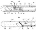
次に本発明の第3の実施の形態を図8を参照して説明する。図8は第3の実施の形態における光走査プローブの先端側の構成を示す。なお、図8(A)は光走査プローブの先端側を斜視図で示し、図8(B)はA−A断面を示す。
【0067】
本実施の形態における光走査プローブ8Cは例えば第1の実施の形態の光走査プローブ8Aにおいて、透明な光学シース35内にその長手方向に線状のマーキング部材56を埋め込んだものである。
【0068】
つまり、観察ビーム48を光走査プローブ8Cの長手方向に垂直方向に出射する光学ユニット36と、光学ユニット36を回転するフレキシブルシャフト32と、それらの外側に有り、柔軟なFEPなどの樹脂チューブ35からなる透明な光学シースが設けられている。光学シースには長手方向に平行に線状のマーキング部材56が埋め込まれている。
【0069】
そして、フレキシブルシャフト32が回転し、それに応じ観測ビーム48が回転し、深さ方向の情報を収集する。観測ビーム48がマーキング部材56を通過するときは、観測ビーム48が遮られ信号が得られないので、マーキングの位置を基準として観測ビーム48の回転位置を知ることができる。画像の再構成はこのマーキングの位置を基準として行う。
【0070】
本実施の形態は観測ビーム48の回転位置を知ることができる効果を有する。その他は第1の実施の形態と同様の効果を有する。
【0071】
その他に、マーキング部材56を内視鏡から観察できるような色などにすると、OCT断層像上の位置と、内視鏡像の位置を対応させて理解することが容易ともなる。
【0072】
図9は第3の実施の形態の変形例を示す。
【0073】
図9(A)では光学シースを形成する樹脂チューブ35の例えば内周面に凹部(切り欠き)91を設けたものであり、図9(B)では樹脂チューブ35の例えば外周面にV字状の切り欠き92を設けたものであり、図9(C)では樹脂チューブ35の例えば内周面の所定の位置で段差状に肉厚が変化する段差部93を設けたものであり、図9(D)では樹脂チューブ35の例えば内周面の所定の角度範囲が薄肉になる薄肉部94をその境界では段差部95で段差状に変化するように設けたものである。
このようなものでも観測ビーム48の回転位置を知ることができる。
【0074】
(第4の実施の形態)
次に本発明の第4の実施の形態を図10を参照して説明する。図10は第4の実施の形態における光走査プローブの先端側の構成を示す。
この光走査プローブ8Dは例えば第1の実施の形態における光走査プローブ8Aにおいて、リニア走査を行う場合の基準位置を検出できるように樹脂チューブ35の先端側の例えば外周面にマーキング部材57をリング状に設けている。
【0075】
なお、第1の実施の形態ではラジアル及びリニア走査(及びこれらの組み合わせのスパイラル走査)ができる駆動機構を備えたのもであるが、本実施の形態はリニア走査のみを行う場合にマーキング部材57は機能する。その他はと同様の構成である。
【0076】
より具体的に説明すると、低干渉性光を伝送するシングルモードファイバ10の先端に設けた光学ユニット36は、該ファイバ10からの光を集光するGRINレンズ46と、このレンズ46からの光を90度に曲げるプリズム47とから構成され、これらがレンズ枠45で保持されている。
【0077】
樹脂チューブ35内に挿通されたフレキシブルシャフト32は図10に対して左右に進退し、観測ビーム48を左右に走査し、深さ方向と左右方向の2次元的な像を得る。光学シースを形成する樹脂チューブ35には周上にマーキング部材57が設けられており、観測ビーム48がマーキング部材を通過すると、観測ビーム48が遮られ信号が得られないので、マーキングの位置を基準として観測ビーム48の走査位置を知ることができる。
【0078】
本実施の形態によれば、光学ユニット36がシース先端に接触しないための走査範囲制御、光走査プローブ8Dの長さが異なる場合の走査範囲制御に用いることができる効果がある。
【0079】
(第5の実施の形態)
次に本発明の第5の実施の形態を図11を参照して説明する。図11は第5の実施の形態における光走査プローブの先端側の構成を示す。
この光走査プローブ8Eは例えば第1の実施の形態における光走査プローブ8Aにおいて、リニア走査を行う場合の基準位置を検出できるように樹脂チューブ35の先端側にその長手方向に櫛状に等間隔にスリット状のマーキング部材59を例えば埋め込むようにして設けている。
【0080】
光学シースを形成する樹脂チューブ35には櫛状に均等の間隔にスリット状のマーキング部材59が設けられ、このマーキング部材59は光を透過する樹脂チューブ35とは異なり、例えば厚い部分では反射する反射体で形成されてており、反射体を通過する毎にその位置を知ることができる
本実施の形態によれば、フレキシブルシャフト32の伸縮による走査ムラがあっても、位置を補正して正しい像を提供することができる効果がある。
【0081】
(第6の実施の形態)
次に本発明の第6の実施の形態を図12を参照して説明する。図12は第6の実施の形態における光走査プローブの先端側の構成を示す。図12(A)は光走査プローブの先端側の構成を縦断面図で示し、図12(B)は図12(A)のB−B断面を示す。
【0082】
この光走査プローブ8Fはフレキシブルシャフト32の先端の光学ユニット36にその長手方向にスリット部材61を設け、かつこのスリット部材61を挟むようにして発光ダイオード(LEDと略記)62aとフォトダイオード62bとを対向するように樹脂チューブ35に固定している。
【0083】
また、LED62aとフォトダイオード62bとは樹脂チューブ35内に埋め込んだリード線63と接続されており、このリード線63は光走査プローブ8Fの後端側に延出され、位置検出装置に接続されている。
【0084】
そして、光学ユニット36が樹脂チューブ35の長手方向に移動された場合、遮光性のスリット部材61に形成した等間隔のスリット孔61aを透過した光をフォトダイオード62bで受光することにより、光学ユニット36のリニア方向の位置を検出できるようにしている。
【0085】
本実施の形態によれば、フレキシブルシャフト32の伸縮による走査ムラがあっても、位置を補正して正しい像を提供することができる。
また、第3ないし第5の実施の形態のように位置検出が観察像に影響を与えない効果もある。
【0086】
(第7の実施の形態)
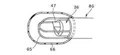
次に本発明の第7の実施の形態を図13を参照して説明する。図13は第7の実施の形態における光走査プローブの先端側の構成を示す。
この光走査プローブ8Gは、例えば図8の第3の実施の形態において、光学シースを形成する樹脂チューブ35の代わりに、金属保護ケース65とバルーン66とを採用している。
【0087】
金属保護ケース65は光学ユニット36を例えば十字状のフレームで覆い、光学ユニット36が回転駆動された場合、十字状のフレーム部分で観察ビームが遮光されることにより、回転方向の位置を検出できるマーキング部材としての機能(作用)を持つようにしている。
【0088】
金属保護ケース65の外側のバルーン66は透明な部材で形成されている。 本実施の形態によれば、ラジアル走査を行った場合、観測ビームの位置を検出することができる。
【0089】
(第8の実施の形態)
次に本発明の第8の実施の形態を図14を参照して説明する。図14は第8の実施の形態における光走査プローブの先端側の構成を示す。
この光走査プローブ8Hは、例えば第1の実施の形態において、レンズ枠45における観察ビーム48が出射される方向と反対側に例えば黒色等に識別し易い色にしたマーキング部71が形成してある。
【0090】
そして、内視鏡から透明な樹脂チューブ35を通してこのマーキング部71を観察できるようにしており、このマーキング部71と反対側に観察ビーム48が出射されていることを知ることができるようにしている。
このマーキング部71により、観察ビーム48の方向を内視鏡から容易に知ることが出来る。
【0091】
(第9の実施の形態)
次に本発明の第9の実施の形態を図15及び図16を参照して説明する。図15は第9の実施の形態における光走査プローブを示し、図16(A)は内視鏡のチャンネル内に光走査プローブを挿通して生体組織を観察している様子を示し、図16(B)はその場合の内視鏡画像を示す。
【0092】
図15に示す第9の実施の形態における光走査プローブ8Iは可撓性のシース73Aと、この可撓性のシース73Aの先端に繋ぎ部材73Bを介して透明で硬質のシース73Cを設け、これらシース73A、繋ぎ部材73B、シース73C内にフレキシブルシャフト32を挿通し、シース73C内でフレキシブルシャフト32の先端に光学ユニット36を取り付けている。
【0093】
このシース73Cにおける観察ビーム48(図16(A)参照)が出射される方向と反対側にマーキング部74をシース73Cの長手方向に線状に形成している。そして、このマーキング部74を内視鏡で観察できるようにしている。
【0094】
例えば、図16(A)に示すように内視鏡75の挿入部76に設けたチャンネル77内に光走査プローブ8Iを挿通し、その先端側を突出させて生体組織11に観察ビーム48を照射して2次元観察像を得ることができる。
【0095】
この場合、挿入部76の先端の照明窓78から照明光が出射され、生体組織11側を照明し、この照明された部分は観察窓79に取り付けた対物レンズにより光学像が結像され、後方の接眼部から図16(B)に示すような内視鏡像を得ることができる。
つまり、内視鏡像中にマーキング部74が観察される位置と反対側に観察ビーム48が出射されていることを知ることができる。
【0096】
(第10の実施の形態)
次に本発明の第10の実施の形態を図17を参照して説明する。図17(A)は第10の実施の形態における光走査プローブの先端側の構成を縦断面図で示し、図17(B)はその横断面でガイド機構の構成を示す。
【0097】
この光走査プローブ8Jは、例えば第1の実施の形態において、レンズ枠45に回り止め用の凸部(或いはピン)81が形成され、かつ光学シースを形成樹脂チューブ35側には、この凸部81が係入され、樹脂チューブ35の長手方向に延びるガイド溝82が設けてある。
【0098】
そして、凸部(或いはピン)81をガイド溝82に収納した状態で光学ユニット36を樹脂チューブ35の長手方向に移動することにより、リニア走査する際に回転するようなことなく、直線的にリニア走査できるようにしている。
【0099】
また、透明な光学シースの観測ビーム48が出射する側と反対側に線状のマーキング部材83を設けて、ラジアル走査した場合に観察ビーム48が基準となる角度位置を確認できるようにしている。
【0100】
さらに説明すると、低干渉性光を伝送するシングルモードファイバ10の先端の光学ユニット36は、ファイバ10からの光を集光するGRINレンズ46と、このレンズ46からの光を90度に曲げるプリズム47とをレンズ枠45でファイバ10の先端に保持している。フレキシブルシャフト32は図17(A)において左右に進退し、観測ビーム48を左右に走査し、深さ方向と左右方向の2次元的な像を得る。
【0101】
レンズ枠45には回り止め用凸部81が、樹脂チューブ35側には肉厚部分にガイド溝82がそれぞれ設けられ、レンズ枠45はその凸部81がガイド溝82に嵌合挿入されながら進退するため、フレキシブルシャフト32のねじれによって走査面が回転するようなことが無い。
なお、本実施の形態はリニア走査する光走査プローブである。
【0102】
本実施の形態によれば、フレキシブルシャフト32のねじれによって走査面が回転すること無く、正確に平面のリニア断層像が得られる。
また、マーキング部材83より走査方向を内視鏡より知るのが容易である。
【0103】
[付記]
1.低干渉光を用いて生体組織の光断層像を得る光イメージング装置において、少なくともその先端は光透過性の良い素材で形成されており、先端が開口していないシースと、光の出射・入射部と、シース内側に挿入された柔軟なパイプ部材と、柔軟なパイプ部材の先端側に取り付けられた前記出射・入射部の保持部材と、パイプ部材の内腔に設けられた低干渉光を伝送する光ファイバとを有し、
パイプ部材を回転させる回転駆動手段と、
パイプ部材を軸方向に進退する進退駆動手段と、
を設けたことを特徴とする光イメージング装置。
【0104】
1−2.パイプ部材が回転駆動するのと同時に進退駆動手段によりパイプ部材が進退することを特徴とする付記1に記載の光イメージング装置。
1−3.パイプ部材および回転駆動手段を有する回転駆動ユニットが一体で進退駆動手段で進退することを特徴とする付記1に記載の光イメージング装置。
1−2−1.第1のシースおよびパイプ部材および回転駆動手段を有するプローブおよび回転駆動ユニットが一体で、進退駆動手段により第2のシースの中で移動することを特徴とする付記1−2に記載の光イメージング装置。
1−3.低干渉光を用いて生体組織の光断層像を得る光イメージング装置において、少なくともその先端は光透過性の良い素材で形成されたシースと、該シース内側に挿入された回転力を伝達するパイプ部材と、該パイプ部材の先端に取り付けられ、光の出射・入射部を設けた光学ユニットと、前記パイプ部材の内腔に設けられた低干渉光を伝送する光ファイバとで構成される光走査プローブと、
パイプ部材を回転させることにより前記光学ユニットから出射される光をラジアル走査するための回転駆動手段と、
パイプ部材を軸方向に進退することにより前記光学ユニットから出射される光をパイプ部材の軸方向にリニア走査するための進退駆動手段と、
を設けたことを特徴とする光イメージング装置。
(1群の背景)本文に記載されている。
【0105】
2.低干渉光を用いて生体組織の光断層像を得る光イメージング装置において、少なくともその先端は光透過性の良い素材で形成されており、先端が開口していないシースと、光の出射・入射部と、シース内側に挿入された柔軟なパイプ部材と、柔軟なパイプ部材の先端側に取り付けられた前記出射・入射部の保持部材と、パイプ部材の内腔に設けられた低干渉光を伝送する光ファイバとを有し、先端部に前記出射・入射部の保持部材の位置検出手段が設けたことを特徴とする光イメージング装置。
【0106】
2−1.シースに走査位置の基準を示すマーキング手段を設けたことを特徴とする付記2に記載の光イメージング装置。
2−1−1.マーキングが光不透過物質で構成されている付記2−1に記載の光イメージング装置。
2−1−2.シースの延長方向に線状のマーキングがされ、パイプ部材が回転走査する(ラジアル走査)付記2−1に記載の光イメージング装置。
2−1−3.シースの鉛直方向に線状のマーキングがされ、パイプ部材がリニア走査する付記2−1に記載の光イメージング装置。
【0107】
2−2.位置検出手段がエンコーダである付記2に記載の光イメージング装置。
(付記2群の背景)先端光学素子をフレキシブルシャフトを用いて、観察ビームを回転走査またはリニア走査する特表平6−511312に開示されたようなプローブでは、挿入部の湾曲などによってフレキシブルシャフトの回転・進退のムラ・遅れにより手元側の走査位置と先端側の走査位置が異なり、走査位置がわからなくなったり、画像中の位置が正確でないという問題があった。
【0108】
このため、走査位置を正確に知る手段を設け、走査位置の正確な観察像を提供及び走査ムラを補正することを目的とし、付記2群の構成にした。
【0109】
3.低干渉光を用いて生体組織の光断層像を得る光イメージング装置において、少なくともその先端は光透過性の良い素材で形成されており、先端が開口していないシースと、光の出射・入射部と、シース内側に挿入された柔軟なパイプ部材と、柔軟なパイプ部材の先端側に取り付けられた前記出射・入射部の保持部材と、パイプ部材の内腔に設けられた低干渉光を伝送する光ファイバとを有し、パイプ部材を軸方向に進退する進退手段を有し、光の出射・入射部からの観察光の照射がプローブの軸方向に略垂直であって、保持部の光が照射される方向の反対側に出射方向を示すマーキングが設けたことを特徴とする光イメージング装置。
3−1シースの光が照射される方向の反対側に出射方向を示すマーキングが設けられている付記3に記載の光イメージング装置。
【0110】
3−1−1.マーキングが線状である付記3−1に記載の光イメージング装置。
(付記3群の背景)リニア走査用光走査プローブでは走査方向がわかりにくく、内視鏡像と対応させて観察位置を対応させるのが困難であった。
【0111】
このため、リニア走査型光走査プローブにおいて、走査方向を内視鏡画像上でわかるようにすることを目的として付記3群の構成にした。
【0112】
4.低干渉光を用いて生体組織の光断層像を得る光イメージング装置において、少なくともその先端は光透過性の良い素材で形成されており、先端が開口していないシースと、光の出射・入射部と、シース内側に挿入された柔軟なパイプ部材と、柔軟なパイプ部材の先端側に取り付けられた前記出射・入射部の保護部材と、パイプ部材の内腔に設けられた低干渉光を伝送する光ファイバとを有し、パイプ部材を軸方向に進退する進退手段を有し、光の出射・入射部からの観察光の出射がプローブの軸方向に垂直であって、保護部材のシースに対する回転を防止する回り止め部材を設けたことを特徴とする光イメージング装置。
【0113】
(付記4の背景)リニア走査型光走査プローブではフレキシブルシャフトのねじりによりリニアの走査面が回転し、観察位置が所望の断面にならないという問題があった。
このため、リニア走査型光走査プローブにおいて、走査のねじれを防止することを目的として、付記4の構成にした。
【0114】
【発明の効果】
以上説明したように本発明によれば、回転駆動手段と進退駆動手段とで駆動した場合の生体組織の光断層像を得ることにより、3次元の断層像を得たり、任意の方向の断面の断層像も得られ、診断し易い画像を提供できる。
【図面の簡単な説明】
【図1】本発明の第1の実施の形態の光イメージング装置の構成を示すブロック図。
【図2】光走査プローブの構成を示す断面図。
【図3】光ロータリジョイントの構成を示す断面図。
【図4】光走査プローブの先端側の構造を示す断面図。
【図5】本実施の形態による走査モードを示す。
【図6】変形例における光ファイバの弛み防止機構を示す図。
【図7】本発明の第2の実施の形態における光走査プローブの先端側の構造を示す断面図。
【図8】本発明の第3の実施の形態における光走査プローブの先端側の構造を示す図。
【図9】第3の実施の形態の変形例におけるマーキング手段を示す図。
【図10】本発明の第4の実施の形態における光走査プローブの先端側の構造を示す断面図。
【図11】本発明の第5の実施の形態における光走査プローブの先端側の構造を示す断面図。
【図12】本発明の第6の実施の形態における光走査プローブの先端側の構造を示す図。
【図13】本発明の第7の実施の形態における光走査プローブの先端側の構造を示す斜視図。
【図14】本発明の第8の実施の形態における光走査プローブの先端側の構造を示す断面図。
【図15】本発明の第9の実施の形態における光走査プローブの先端側の構造を示す側面図。
【図16】光走査プローブを内視鏡のチャンネルに挿通した様子及び内視鏡像を示す図。
【図17】本発明の第10の実施の形態における光走査プローブの先端側の構造を示す図。
【符号の説明】
1…光イメージング装置
2…低干渉性光源
3…第1のシングルモードファイバ
4…光カップラ部
5…第2のシングルモードファイバ
6…弛み防止手段
7…駆動部
8A…光走査プローブ
9…光ロータリジョイント
10…第3のシングルモードファイバ
11…生体組織
13…回転/進退制御装置
14…光路長の可変機構
16…グレーティング
18…ステージ
19…ガルバノメータミラー
20…ガルバノメータコントローラ
25…コンピュータ
26…モニタ
28…モード入力部
31…フレーム
32…フレキシブルシャフト
33…回転用モータ
34…ギヤ
35…樹脂チューブ
36…光学ユニット
39…ボールネジ
40…リニア移動用モータ(進退移動用モータ)
45…レンズ枠
46…GRINレンズ
47…プリズム
46…観測ビーム[0001]
BACKGROUND OF THE INVENTION
The present invention relates to an optical imaging apparatus that obtains an optical tomographic image of a living tissue using low coherent light.
[0002]
[Prior art]
In recent years, an optical imaging apparatus that uses low coherence light, transmits the light to a tip optical element via a fiber in a flexible shaft, and rotates the tip optical element together with the flexible shaft to rotate and scan an observation beam. 6-511312.
With the probe employed in this optical imaging apparatus, only a two-dimensional image can be obtained.
[0003]
[Problems to be solved by the invention]
To grasp an accurate three-dimensional structure of an affected area, a doctor has conventionally estimated and understood a three-dimensional image in the head from a two-dimensional image, but skill is required. In addition, there is a drawback that a tomographic image in an arbitrary direction cannot be obtained, and it is difficult to quantitatively measure the size of the affected area.
[0004]
(Object of invention)
The present invention has been made in view of the above points.By obtaining an optical tomographic image of a living tissue when driven by the rotation driving means and the advance / retreat driving means, a three-dimensional tomographic image or a tomographic image of a cross section in an arbitrary direction can be obtained. Can offerAn object is to provide an optical imaging apparatus.
[0005]
[Means for Solving the Problems]
An optical imaging apparatus according to an aspect of the present invention is an optical imaging apparatus that obtains an optical tomographic image of a biological tissue using low interference light.
At least its tip is formed of a material with good light transmission, and a sheath whose tip is not open,
A light exit / incident part;
A flexible pipe member inserted inside the sheath;
The exit / incident part holding member attached to the distal end side of the flexible pipe member,
An optical fiber that transmits low interference light provided in the lumen of the pipe member,
Rotation driving means for rotating the pipe member;
Advancing and retracting drive means for advancing and retracting the pipe member in the axial direction;
A slack absorbing means for absorbing slack of the optical fiber at the time of forward / backward driving by the forward / backward driving means;
Drive control means for controlling the drive of the rotation drive means and the advance / retreat drive means in accordance with the scanning mode of the emitted light of the exit / incident part;
Provided,
The sheath has a first sheath and a second sheath provided inside the first sheath, the pipe member is inserted inside the second sheath, and the second sheath is The forward / backward drive means moves forward and backward in the axial direction together with the pipe member.
[0006]
DETAILED DESCRIPTION OF THE INVENTION
Embodiments of the present invention will be described below with reference to the drawings.
(First embodiment)
1 to 6 relate to the first embodiment of the present invention, FIG. 1 shows the configuration of the optical imaging apparatus of the first embodiment of the present invention, FIG. 2 shows the configuration of the optical scanning probe, 3 shows the configuration of the optical rotary joint, FIG. 4 shows the configuration of the tip side of the optical scanning probe, FIG. 5 shows the scanning mode according to the present embodiment, and FIG. 6 shows the slack prevention mechanism in the modification.
[0007]
An optical imaging apparatus (optical tomographic imaging apparatus) 1 according to the first embodiment of the present invention shown in FIG. 1 has a low coherence light source 2 such as an ultra-high luminance light emitting diode (hereinafter abbreviated as SLD). The low-coherence light source 2 has a feature of low-coherence light that exhibits coherence only in a short distance range in which the wavelength is, for example, 1300 nm and the coherence distance is, for example, about 17 μm.
[0008]
In other words, for example, when this light is branched into two and then mixed again, if the difference between the two optical path lengths from the branched point to the mixed point is within a short distance range of about 17 μm, it is regarded as interfering light. When it is detected and the optical path length is longer than that, it shows a characteristic that does not interfere.
[0009]
The light of the low coherence light source 2 is incident on one end of the first
The first
[0010]
On the tip side of the first single mode fiber 3 (from the optical coupler section 4), optical fiber slack preventing means 6 for the case where the
[0011]
The optical fiber slack prevention means 6 is looped, for example, about several centimeters (more specifically, 5 cm), and the influence of the slack of the optical fiber on the case where the
[0012]
The
[0013]
The transmitted light is irradiated while being scanned from the distal end side of the
[0014]
Further, the
[0015]
Further, an optical path
[0016]
For example, a grating 16 is disposed via a
[0017]
The
[0018]
That is, a drive signal is applied by the
[0019]
Then, the optical path length of the light emitted from the end face of the second single mode fiber 5 by this rotational vibration, reflected by the
[0020]
That is, the
[0021]
The light whose optical path length is changed by the optical path
[0022]
For example, in the second single mode fiber 5, when the
[0023]
The optical scanning probe 8 causes the
The driving operation of the
[0024]
The signal photoelectrically converted by the
[0025]
In addition, the
[0026]
The
[0027]
Further, the reference timing control signal when rotating / retracting by the rotation / advance control device 13 and the reference timing control signal when rotating the galvanometer mirror by the
[0028]
In other words, the video synchronization signal of the
The structure of the
The distal end side of the first
[0029]
A rotation (drive)
[0030]
This rotation is transmitted to the third
[0031]
The
[0032]
In addition, the light reflected on the
[0033]
The distal end of the
[0034]
The
[0035]
A
[0036]
The rear end of the linear
[0037]
The optical rotary joint 9 has a structure as shown in FIG.
As shown in FIG. 3, the optical rotary joint 9 has a cylindrical enlarged diameter portion at the rear end of the
[0038]
Further, the rear end of the third
[0039]
Further, the
[0040]
A
[0041]
The tip of the third
[0042]
Further, the reflected light on the
The effect | action by 1st Embodiment of such a structure is demonstrated below.
[0043]
After setting as shown in FIG. 1, a user such as an operator inputs a mode instruction to obtain an optical imaging image from the
[0044]
In this case, in FIG. 2, the rotation of the
[0045]
When the linear scan mode is instructed, the rotation / advance control device 13 drives the advance /
[0046]
In this case, the
[0047]
When the three-dimensional scan or spiral scan mode is instructed, the rotation / retraction control device 13 drives the
[0048]
In this case, if the scanning is performed so that the rotational scanning is sufficiently faster than the linear scanning, a three-dimensional construction image can be obtained by stacking two-dimensional circumferential images. If three-dimensional data can be constructed, a free cross section can be constructed for the data.
[0049]
That is, when an optical imaging image in this three-dimensional scan mode is obtained, image data of the optical imaging image in that mode is stored in an image data storage device such as a memory in the
[0050]
Therefore, according to the present embodiment, the
[0051]
Furthermore, since a tomographic image from an arbitrary direction can be displayed, it is easy for the surgeon to make an accurate diagnosis on the site of interest. That is, it is possible to provide a surgeon with a three-dimensional image that is easy to diagnose and a tomographic image in an arbitrary direction.
[0052]
Note that the
[0053]
Therefore, this embodiment has the following effects.
Both a radial image and a linear image can be obtained, a 3D image can be obtained, and a 2D image with a desired cross section can also be obtained. It is easy for the surgeon to grasp the affected area from these images. Easy diagnosis.
[0054]
In addition, according to the present embodiment, even when an optical scanning probe whose scanning mode is limited to linear scanning or the like is connected to the observation apparatus, an optical tomographic image is scanned in that scanning mode. Can be obtained.
In this case, a connector structure that can be easily attached and detached by the observation apparatus may be used.
[0055]
In the present embodiment, by encapsulating a
[0056]
Next, a modification of the first embodiment will be described. This modification is different from the first embodiment shown in FIG. 1 only in the configuration of the fiber slack preventing means. As shown in FIG. 6, in this modification, the first
This moving means is controlled to move in conjunction with the linear movement of the probe 8. The
[0057]
(Second Embodiment)
Next, a second embodiment of the present invention will be described with reference to FIG. FIG. 7 shows the configuration of the distal end side of the optical scanning probe according to the second embodiment, and FIG. 7B shows the inner tube 35B side moved from the state of FIG. 7A to the proximal end side of the optical scanning probe. Indicates the state.
In the present embodiment, the
[0058]
The
[0059]
That is, the
[0060]
In the present embodiment, the
In addition, the inner tube 35B is filled with a
[0061]
The rear end of the
[0062]
When the
A
The rear end of the
The other configuration is the same as that of the first embodiment.
[0063]
According to the present embodiment, it is possible to prevent rotation unevenness due to a change in friction of the
Moreover, the optical scanning probe for radial scanning can be diverted and can be made inexpensive.
[0064]
As a modification of the second embodiment, when a two-dimensional image obtained by radial scanning is stored in a memory in a time series and freezes, the phrase is not actually a signal after the freeze but a phrase is actually used. Recalls an image from the memory, displays it, and prints it out.
[0065]
Further, the memory may be used to store a continuous two-dimensional image obtained while performing linear scanning and to perform three-dimensional reconstruction.
According to this modification, there is an effect that an image at the moment of freezing can be obtained.
[0066]
(Third embodiment)
Next, a third embodiment of the present invention will be described with reference to FIG. FIG. 8 shows the configuration of the distal end side of the optical scanning probe in the third embodiment. 8A shows a perspective view of the tip side of the optical scanning probe, and FIG. 8B shows a cross section taken along the line AA.
[0067]
The
[0068]
That is, from the
[0069]
Then, the
[0070]
This embodiment has an effect that the rotational position of the
[0071]
In addition, when the marking
[0072]
FIG. 9 shows a modification of the third embodiment.
[0073]
In FIG. 9A, a recess (notch) 91 is provided, for example, on the inner peripheral surface of the
Even in such a case, the rotational position of the
[0074]
(Fourth embodiment)
Next, a fourth embodiment of the present invention will be described with reference to FIG. FIG. 10 shows the configuration of the distal end side of the optical scanning probe in the fourth embodiment.
The optical scanning probe 8D has, for example, a ring-shaped marking
[0075]
In the first embodiment, a driving mechanism capable of radial and linear scanning (and a combination of spiral scanning) is provided. However, in this embodiment, the marking
[0076]
More specifically, the
[0077]
The
[0078]
According to the present embodiment, there is an effect that can be used for scanning range control for preventing the
[0079]
(Fifth embodiment)
Next, a fifth embodiment of the present invention will be described with reference to FIG. FIG. 11 shows the configuration of the distal end side of the optical scanning probe in the fifth embodiment.
For example, in the
[0080]
The
According to the present embodiment, even if there is scanning unevenness due to expansion and contraction of the
[0081]
(Sixth embodiment)
Next, a sixth embodiment of the present invention will be described with reference to FIG. FIG. 12 shows the configuration of the distal end side of the optical scanning probe in the sixth embodiment. 12A is a longitudinal sectional view showing the configuration of the tip side of the optical scanning probe, and FIG. 12B is a BB cross section of FIG. 12A.
[0082]
In this
[0083]
The LED 62a and the photodiode 62b are connected to a
[0084]
When the
[0085]
According to the present embodiment, even if there is scanning unevenness due to expansion and contraction of the
Further, as in the third to fifth embodiments, there is an effect that the position detection does not affect the observation image.
[0086]
(Seventh embodiment)
Next, a seventh embodiment of the present invention will be described with reference to FIG. FIG. 13 shows the configuration of the distal end side of the optical scanning probe in the seventh embodiment.
For example, in the third embodiment shown in FIG. 8, this
[0087]
The metal
[0088]
The
[0089]
(Eighth embodiment)
Next, an eighth embodiment of the present invention will be described with reference to FIG. FIG. 14 shows the configuration of the distal end side of the optical scanning probe in the eighth embodiment.
In the
[0090]
Then, the marking
With this marking
[0091]
(Ninth embodiment)
Next, a ninth embodiment of the present invention will be described with reference to FIGS. FIG. 15 shows an optical scanning probe according to the ninth embodiment, and FIG. 16A shows a state in which a biological tissue is observed by inserting the optical scanning probe into the channel of the endoscope. B) shows an endoscopic image in that case.
[0092]
The optical scanning probe 8I in the ninth embodiment shown in FIG. 15 is provided with a
[0093]
A marking
[0094]
For example, as shown in FIG. 16A, the optical scanning probe 8I is inserted into a
[0095]
In this case, illumination light is emitted from the
That is, it can be known that the
[0096]
(Tenth embodiment)
Next, a tenth embodiment of the present invention will be described with reference to FIG. FIG. 17A is a longitudinal sectional view showing the configuration of the distal end side of the optical scanning probe in the tenth embodiment, and FIG. 17B is a cross sectional view showing the configuration of the guide mechanism.
[0097]
In the
[0098]
Then, by moving the
[0099]
In addition, a
[0100]
More specifically, the
[0101]
The
The present embodiment is an optical scanning probe that performs linear scanning.
[0102]
According to the present embodiment, a flat linear tomographic image can be obtained accurately without the scanning plane rotating due to the twist of the
In addition, it is easy to know the scanning direction from the endoscope using the marking
[0103]
[Appendix]
1. In an optical imaging apparatus that obtains an optical tomographic image of a living tissue using low-interference light, at least the tip of the optical imaging device is formed of a material having good light transmission, a sheath that does not open the tip, and a light emitting / incident part A flexible pipe member inserted inside the sheath, a holding member for the emission / incident part attached to the distal end side of the flexible pipe member, and low interference light provided in the lumen of the pipe member An optical fiber,
Rotation driving means for rotating the pipe member;
Advancing and retracting drive means for advancing and retracting the pipe member in the axial direction;
An optical imaging apparatus comprising:
[0104]
1-2. 2. The optical imaging apparatus according to
1-3. 2. The optical imaging apparatus according to
1-2-1. The optical imaging apparatus according to appendix 1-2, wherein the probe having the first sheath, the pipe member, and the rotation driving unit and the rotation driving unit are integrally moved in the second sheath by the advance / retreat driving unit. .
1-3. In an optical imaging apparatus that obtains an optical tomographic image of a living tissue using low interference light, at least the tip of the sheath is formed of a material having good light transmission, and a pipe member that transmits a rotational force inserted inside the sheath And an optical unit attached to the tip of the pipe member and provided with a light emitting / incident part, and an optical fiber for transmitting low-interference light provided in the lumen of the pipe member When,
Rotation driving means for radial scanning of light emitted from the optical unit by rotating a pipe member;
Advancing and retracting drive means for linearly scanning the light emitted from the optical unit by moving the pipe member in the axial direction in the axial direction of the pipe member;
An optical imaging apparatus comprising:
(Group of backgrounds) Described in the text.
[0105]
2. In an optical imaging apparatus that obtains an optical tomographic image of a living tissue using low-interference light, at least the tip of the optical imaging device is formed of a material having good light transmission, a sheath that does not open the tip, and a light emitting / incident part A flexible pipe member inserted inside the sheath, a holding member for the emission / incident part attached to the distal end side of the flexible pipe member, and low interference light provided in the lumen of the pipe member An optical imaging apparatus comprising: an optical fiber; and a position detecting unit for the exit / incident part holding member provided at a distal end.
[0106]
2-1. The optical imaging apparatus according to appendix 2, wherein marking means for indicating a reference of a scanning position is provided on the sheath.
2-1-1. The optical imaging apparatus according to appendix 2-1, wherein the marking is made of a light-impermeable material.
2-1-2. The optical imaging apparatus according to appendix 2-1, wherein linear marking is provided in the extending direction of the sheath and the pipe member is rotationally scanned (radial scanning).
2-1-3. The optical imaging apparatus according to appendix 2-1, wherein linear marking is performed in a vertical direction of the sheath and the pipe member linearly scans.
[0107]
2-2. The optical imaging apparatus according to appendix 2, wherein the position detecting means is an encoder.
(Background of Supplementary Group 2) With a probe as disclosed in Japanese Translation of PCT Publication No. 6-511112 in which the tip optical element is rotated or linearly scanned with a flexible shaft using a flexible shaft, the flexible shaft is There is a problem that the scanning position on the proximal side and the scanning position on the leading end side are different due to unevenness / delay of rotation / retraction, and the scanning position is not known or the position in the image is not accurate.
[0108]
For this reason, a means for accurately knowing the scanning position is provided, and an object of providing an accurate observation image of the scanning position and correcting the scanning unevenness are configured in the appendix 2 group.
[0109]
3. In an optical imaging apparatus that obtains an optical tomographic image of a living tissue using low-interference light, at least the tip of the optical imaging device is formed of a material having good light transmission, a sheath that does not open the tip, and a light emitting / incident part A flexible pipe member inserted inside the sheath, a holding member for the emission / incident part attached to the distal end side of the flexible pipe member, and low interference light provided in the lumen of the pipe member An optical fiber, and an advancing / retracting means for advancing and retreating the pipe member in the axial direction. The irradiation of observation light from the light emitting / incident part is substantially perpendicular to the axial direction of the probe, An optical imaging apparatus, wherein a marking indicating an emission direction is provided on a side opposite to an irradiation direction.
The optical imaging apparatus according to
[0110]
3-1-1. The optical imaging apparatus according to appendix 3-1, wherein the marking is linear.
(Background of Supplementary Group 3) With the optical scanning probe for linear scanning, the scanning direction is difficult to understand, and it is difficult to associate the observation position with the endoscopic image.
[0111]
For this reason, in the linear scanning type optical scanning probe, the configuration of
[0112]
4). In an optical imaging apparatus that obtains an optical tomographic image of a living tissue using low-interference light, at least the tip of the optical imaging device is formed of a material having good light transmission, a sheath that does not open the tip, and a light emitting / incident part And a flexible pipe member inserted inside the sheath, a protection member for the emission / incident part attached to the distal end side of the flexible pipe member, and low interference light provided in the lumen of the pipe member An optical fiber, and an advancing / retracting means for advancing and retreating the pipe member in the axial direction, and the observation light emission from the light emission / incident part is perpendicular to the probe axial direction, and the protective member rotates with respect to the sheath An optical imaging apparatus comprising a detent member for preventing the rotation.
[0113]
(Background of Supplementary Note 4) The linear scanning optical scanning probe has a problem that the linear scanning surface rotates due to torsion of the flexible shaft, and the observation position does not become a desired cross section.
For this reason, in the linear scanning type optical scanning probe, the configuration of Supplementary Note 4 is adopted for the purpose of preventing scanning twisting.
[0114]
【The invention's effect】
As explained above, according to the present invention,, TimesBy obtaining an optical tomographic image of a living tissue when driven by a rolling drive means and advancing / retreating drive means, a three-dimensional tomographic image or a tomographic image of a cross section in an arbitrary direction can be obtained. Can be provided.
[Brief description of the drawings]
FIG. 1 is a block diagram showing a configuration of an optical imaging apparatus according to a first embodiment of the present invention.
FIG. 2 is a cross-sectional view showing a configuration of an optical scanning probe.
FIG. 3 is a cross-sectional view showing a configuration of an optical rotary joint.
FIG. 4 is a cross-sectional view showing the structure on the distal end side of the optical scanning probe.
FIG. 5 shows a scanning mode according to the present embodiment.
FIG. 6 is a view showing an optical fiber slack preventing mechanism in a modified example.
FIG. 7 is a cross-sectional view showing the structure on the distal end side of an optical scanning probe in a second embodiment of the present invention.
FIG. 8 is a diagram showing a structure on the distal end side of an optical scanning probe in a third embodiment of the present invention.
FIG. 9 is a diagram showing marking means in a modification of the third embodiment.
FIG. 10 is a cross-sectional view showing the structure on the distal end side of an optical scanning probe in a fourth embodiment of the invention.
FIG. 11 is a cross-sectional view showing the structure of the distal end side of an optical scanning probe according to a fifth embodiment of the invention.
FIG. 12 is a diagram showing a structure on the tip side of an optical scanning probe in a sixth embodiment of the invention.
FIG. 13 is a perspective view showing the structure of the distal end side of an optical scanning probe according to a seventh embodiment of the invention.
FIG. 14 is a cross-sectional view showing the structure on the distal end side of an optical scanning probe according to an eighth embodiment of the invention.
FIG. 15 is a side view showing the structure of the distal end side of an optical scanning probe according to a ninth embodiment of the invention.
FIG. 16 is a diagram showing a state in which an optical scanning probe is inserted into a channel of an endoscope and an endoscopic image.
FIG. 17 is a view showing the structure on the distal end side of an optical scanning probe in a tenth embodiment of the invention.
[Explanation of symbols]
1. Optical imaging device
2 ... Low coherence light source
3. First single mode fiber
4 ... Optical coupler
5 ... Second single mode fiber
6 ... Slack prevention means
7 ... Drive unit
8A ... Optical scanning probe
9 ... Optical rotary joint
10: Third single mode fiber
11 ... Living tissue
13 ... Rotation / retraction control device
14: Optical path length variable mechanism
16 ... Grating
18 ... Stage
19 ... Galvanometer mirror
20 ... Galvanometer controller
25. Computer
26 ... Monitor
28 ... Mode input section
31 ... Frame
32 ... Flexible shaft
33 ... Motor for rotation
34 ... Gear
35 ... Resin tube
36 ... Optical unit
39 ... Ball screw
40 ... Linear movement motor (advance / retreat motor)
45 ... Lens frame
46 ... GRIN lens
47 ... Prism
46 ... Observation beam
Claims (7)
Translated fromJapanese少なくともその先端は光透過性の良い素材で形成されており、先端が開口していないシースと、
光の出射・入射部と、
前記シースの内側に挿入された柔軟なパイプ部材と、
前記柔軟なパイプ部材の先端側に取り付けられた前記出射・入射部の保持部材と、
前記パイプ部材の内腔に設けられた低干渉光を伝送する光ファイバと、を有し、
前記パイプ部材を回転させる回転駆動手段と、
前記パイプ部材を軸方向に進退する進退駆動手段と、
前記進退駆動手段による進退駆動時の前記光ファイバの弛みを吸収する弛み吸収手段と、
前記出射・入射部の出射光の走査モードに応じて回転駆動手段及び進退駆動手段の駆動を制御する駆動制御手段と、
を設け、
前記シースは第1のシースと、前記第1のシースの内部に設けられた第2のシースとを有し、前記パイプ部材は前記第2のシースの内側に挿入され、前記第2のシースは前記進退駆動手段により前記パイプ部材と共に前記軸方向に進退することを特徴とする光イメージング装置。In an optical imaging device that obtains an optical tomographic image of biological tissue using low interference light,
At least its tip is formed of a material having good light transmission, and a sheath whose tip is not open,
A light exit / incident section;
A flexible pipe member inserted inside the sheath;
The exit / incident part holding member attached to the distal end side of the flexible pipe member,
An optical fiber that transmits low interference light provided in the lumen of the pipe member,
Rotation driving means for rotating the pipe member;
Advancing and retracting drive means for advancing and retracting the pipe member in the axial direction;
A slack absorbing means for absorbing slack of the optical fiber at the time of forward / backward driving by the forward / backward driving means;
Drive control means for controlling the drive of the rotation drive means and the advance / retreat drive means in accordance with the scanning mode of the emitted light of the exit / incident part;
Provided,
The sheath has a first sheath and a second sheath provided inside the first sheath, the pipe member is inserted inside the second sheath, and the second sheath An optical imaging apparatus characterizedby moving forward and backward in the axial direction together with the pipe member by the advance / retreat driving means .
Priority Applications (1)
| Application Number | Priority Date | Filing Date | Title |
|---|---|---|---|
| JP13459099AJP4262355B2 (en) | 1999-05-14 | 1999-05-14 | Optical imaging device |
Applications Claiming Priority (1)
| Application Number | Priority Date | Filing Date | Title |
|---|---|---|---|
| JP13459099AJP4262355B2 (en) | 1999-05-14 | 1999-05-14 | Optical imaging device |
Publications (3)
| Publication Number | Publication Date |
|---|---|
| JP2000321034A JP2000321034A (en) | 2000-11-24 |
| JP2000321034A5 JP2000321034A5 (en) | 2006-06-22 |
| JP4262355B2true JP4262355B2 (en) | 2009-05-13 |
Family
ID=15131948
Family Applications (1)
| Application Number | Title | Priority Date | Filing Date |
|---|---|---|---|
| JP13459099AExpired - Fee RelatedJP4262355B2 (en) | 1999-05-14 | 1999-05-14 | Optical imaging device |
Country Status (1)
| Country | Link |
|---|---|
| JP (1) | JP4262355B2 (en) |
Families Citing this family (43)
| Publication number | Priority date | Publication date | Assignee | Title |
|---|---|---|---|---|
| JP2002263055A (en)* | 2001-03-12 | 2002-09-17 | Olympus Optical Co Ltd | Tip hood for endoscope |
| US7206067B2 (en)* | 2001-05-17 | 2007-04-17 | Oticon A/S | Method and apparatus for obtaining geometrical data relating to the ear canal of the human body |
| WO2002091915A1 (en)* | 2001-05-17 | 2002-11-21 | Oticon A/S | Method and apparatus for obtaining position data relating to a probe in the ear canal |
| JP4754743B2 (en)* | 2001-09-18 | 2011-08-24 | オリンパス株式会社 | Endoscope device |
| DE102004008367A1 (en)* | 2004-02-20 | 2005-09-22 | Siemens Ag | Method for taking two-dimensional images inside a blood-perfused vessel by means of optical coherence tomography |
| EP2272421A1 (en)* | 2004-08-24 | 2011-01-12 | The General Hospital Corporation | Method and apparatus for imaging of vessel segments |
| JP5695001B2 (en)* | 2004-11-02 | 2015-04-01 | ザ ジェネラル ホスピタル コーポレイション | Optical fiber rotator, optical system and method for sample imaging |
| JP4685467B2 (en)* | 2005-02-07 | 2011-05-18 | 富士フイルム株式会社 | Probe for OCT diagnostic imaging equipment |
| JP4647327B2 (en)* | 2005-02-07 | 2011-03-09 | 富士フイルム株式会社 | Probe unit for OCT diagnostic imaging equipment |
| WO2006086700A2 (en)* | 2005-02-10 | 2006-08-17 | Lightlab Imaging, Inc. | Optical coherence tomography apparatus and methods |
| JP2007020797A (en)* | 2005-07-14 | 2007-02-01 | Olympus Medical Systems Corp | Endoscope |
| DE102005045088B4 (en)* | 2005-09-21 | 2007-05-16 | Siemens Ag | Optical coherence tomography system |
| JP4640813B2 (en) | 2005-09-30 | 2011-03-02 | 富士フイルム株式会社 | Optical probe and optical tomographic imaging apparatus |
| DE102005062130A1 (en)* | 2005-12-23 | 2007-06-28 | Isis Sentronics Gmbh | Scanning system includes sensor with transport module and bearing section as well as device for mounting the module |
| DK1973466T3 (en)* | 2006-01-19 | 2021-02-01 | Massachusetts Gen Hospital | BALLOON IMAGING CATHETER |
| JP2007309882A (en)* | 2006-05-22 | 2007-11-29 | Fujifilm Corp | Wavelength sweep light source and optical tomographic imaging apparatus |
| JP4338142B2 (en)* | 2006-08-31 | 2009-10-07 | 国立長寿医療センター総長 | Dental optical tomographic image display system |
| JP2008067889A (en)* | 2006-09-14 | 2008-03-27 | Pentax Corp | Optical coherence tomography probe for linear scanning endoscope |
| JPWO2008081653A1 (en)* | 2006-12-28 | 2010-04-30 | テルモ株式会社 | Optical probe |
| JP4895840B2 (en)* | 2007-01-31 | 2012-03-14 | Hoya株式会社 | OCT system |
| JP2008191022A (en)* | 2007-02-06 | 2008-08-21 | Hoya Corp | Oct system |
| JP4836820B2 (en)* | 2007-02-06 | 2011-12-14 | Hoya株式会社 | OCT system |
| WO2009137704A1 (en)* | 2008-05-07 | 2009-11-12 | Volcano Corporation | Optical imaging catheter for aberration balancing |
| EP2037214A1 (en)* | 2007-09-14 | 2009-03-18 | Leica Geosystems AG | Method and measuring device for measuring surfaces |
| JP5069585B2 (en)* | 2008-02-25 | 2012-11-07 | 富士フイルム株式会社 | Optical tomographic imaging system using an optical probe |
| JP5241293B2 (en)* | 2008-04-01 | 2013-07-17 | 富士フイルム株式会社 | Optical tomographic image acquisition apparatus and method |
| JP5244471B2 (en)* | 2008-06-17 | 2013-07-24 | 富士フイルム株式会社 | Electronic endoscope |
| JP2010043994A (en)* | 2008-08-15 | 2010-02-25 | Fujifilm Corp | Optical probe and three-dimensional image acquiring apparatus |
| JP5221264B2 (en)* | 2008-09-25 | 2013-06-26 | 富士フイルム株式会社 | Rotary joint and optical tomographic imaging apparatus using the same |
| JP5236573B2 (en)* | 2009-05-14 | 2013-07-17 | 富士フイルム株式会社 | Optical structure measuring device and optical probe thereof |
| WO2010137375A1 (en)* | 2009-05-28 | 2010-12-02 | コニカミノルタオプト株式会社 | Optical connector and optical tomograph |
| JP5577513B2 (en)* | 2010-01-29 | 2014-08-27 | 公益財団法人ヒューマンサイエンス振興財団 | Reference grating, method of using the reference grating, and optical coherence tomography diagnostic apparatus including the reference grating |
| WO2011132664A1 (en)* | 2010-04-23 | 2011-10-27 | コニカミノルタオプト株式会社 | Probe and use method therefor |
| JP6349881B2 (en)* | 2014-03-31 | 2018-07-04 | 株式会社ニデック | Optical tomography system |
| JP5983676B2 (en)* | 2014-05-16 | 2016-09-06 | 住友電気工業株式会社 | Optical probe |
| US9709388B2 (en)* | 2015-05-20 | 2017-07-18 | Namiki Seimitsu Houseki Kabushiki Kaisha | Optical inner surface measuring device |
| CN106289055B (en)* | 2015-06-05 | 2019-02-15 | 安达满纳米奇精密宝石有限公司 | Optical inner surface measuring device |
| FR3048077B1 (en)* | 2016-02-23 | 2020-05-22 | Mesure-Systems3D | NON-CONTACT THREE-DIMENSIONAL MONITORING DEVICE OF A HOLLOW PART WITH AN INTERNAL REVOLUTION SURFACE, CORRESPONDING METHOD, COMPUTER PROGRAM PRODUCT AND MEDIUM |
| JP2018185190A (en)* | 2017-04-25 | 2018-11-22 | リコーインダストリアルソリューションズ株式会社 | Gas detection method and gas detection system |
| US10845549B2 (en)* | 2018-02-08 | 2020-11-24 | Canon U.S.A., Inc. | Multiplex optical fiber connector |
| WO2021100792A1 (en)* | 2019-11-21 | 2021-05-27 | アダマンド並木精密宝石株式会社 | Optical inner surface measurement device and optical inner surface measurement method |
| CN113758442A (en)* | 2021-09-27 | 2021-12-07 | 中国科学院沈阳自动化研究所 | Device and method for non-contact small diameter tube lumen topography detection based on low coherence interference |
| CN118913142B (en)* | 2024-10-10 | 2025-02-11 | 苏州杜蒙智能科技有限公司 | Portable handheld 3D scanner |
- 1999
- 1999-05-14JPJP13459099Apatent/JP4262355B2/ennot_activeExpired - Fee Related
Also Published As
| Publication number | Publication date |
|---|---|
| JP2000321034A (en) | 2000-11-24 |
Similar Documents
| Publication | Publication Date | Title |
|---|---|---|
| JP4262355B2 (en) | Optical imaging device | |
| JP4021975B2 (en) | Optical scanning probe device | |
| JP4963913B2 (en) | Optical coherence tomographic imaging system | |
| JP4160603B2 (en) | Optical imaging device | |
| US6546272B1 (en) | Apparatus for in vivo imaging of the respiratory tract and other internal organs | |
| US6069698A (en) | Optical imaging apparatus which radiates a low coherence light beam onto a test object, receives optical information from light scattered by the object, and constructs therefrom a cross-sectional image of the object | |
| JP5704516B2 (en) | Probe for optical tomographic image measuring apparatus and method for adjusting probe | |
| JP4037538B2 (en) | Optical imaging device | |
| JP3947275B2 (en) | Endoscope | |
| US20050234347A1 (en) | Puncture-type endoscopic probe | |
| JP2000097846A5 (en) | Optical scanning probe device and optical imaging device | |
| JP2000097846A (en) | Optical scanning probe device | |
| US20110077463A1 (en) | Optical probe and endoscope apparatus | |
| JP2002263106A (en) | Optical probe device | |
| JPH11148897A (en) | Optical imaging device | |
| JP2007530945A (en) | Forward scanning imaging fiber optic detector | |
| JP2001079007A (en) | Optical probe device | |
| JP2002005822A (en) | Optical probe device | |
| JP2022501152A (en) | Overmolded distal optics for intracavitary optical probes | |
| JP5429447B2 (en) | Optical tomographic image measuring device | |
| JP2011072401A (en) | Optical probe and endoscope apparatus | |
| JP2011056165A (en) | Oct system | |
| JP4895840B2 (en) | OCT system | |
| JP6439098B2 (en) | Optical imaging probe | |
| JP2001087269A (en) | Optical probe device |
Legal Events
| Date | Code | Title | Description |
|---|---|---|---|
| A521 | Request for written amendment filed | Free format text:JAPANESE INTERMEDIATE CODE: A523 Effective date:20060428 | |
| A621 | Written request for application examination | Free format text:JAPANESE INTERMEDIATE CODE: A621 Effective date:20060428 | |
| A131 | Notification of reasons for refusal | Free format text:JAPANESE INTERMEDIATE CODE: A131 Effective date:20080205 | |
| A521 | Request for written amendment filed | Free format text:JAPANESE INTERMEDIATE CODE: A523 Effective date:20080407 | |
| A02 | Decision of refusal | Free format text:JAPANESE INTERMEDIATE CODE: A02 Effective date:20080603 | |
| A521 | Request for written amendment filed | Free format text:JAPANESE INTERMEDIATE CODE: A523 Effective date:20080804 | |
| A911 | Transfer to examiner for re-examination before appeal (zenchi) | Free format text:JAPANESE INTERMEDIATE CODE: A911 Effective date:20080917 | |
| A131 | Notification of reasons for refusal | Free format text:JAPANESE INTERMEDIATE CODE: A131 Effective date:20081111 | |
| A521 | Request for written amendment filed | Free format text:JAPANESE INTERMEDIATE CODE: A523 Effective date:20081201 | |
| TRDD | Decision of grant or rejection written | ||
| A01 | Written decision to grant a patent or to grant a registration (utility model) | Free format text:JAPANESE INTERMEDIATE CODE: A01 Effective date:20090120 | |
| A01 | Written decision to grant a patent or to grant a registration (utility model) | Free format text:JAPANESE INTERMEDIATE CODE: A01 | |
| A61 | First payment of annual fees (during grant procedure) | Free format text:JAPANESE INTERMEDIATE CODE: A61 Effective date:20090209 | |
| FPAY | Renewal fee payment (event date is renewal date of database) | Free format text:PAYMENT UNTIL: 20120220 Year of fee payment:3 | |
| FPAY | Renewal fee payment (event date is renewal date of database) | Free format text:PAYMENT UNTIL: 20120220 Year of fee payment:3 | |
| FPAY | Renewal fee payment (event date is renewal date of database) | Free format text:PAYMENT UNTIL: 20120220 Year of fee payment:3 | |
| FPAY | Renewal fee payment (event date is renewal date of database) | Free format text:PAYMENT UNTIL: 20130220 Year of fee payment:4 | |
| FPAY | Renewal fee payment (event date is renewal date of database) | Free format text:PAYMENT UNTIL: 20140220 Year of fee payment:5 | |
| LAPS | Cancellation because of no payment of annual fees |