JP4259744B2 - Fuel supply system for 4-cycle engine for outboard motor - Google Patents
Fuel supply system for 4-cycle engine for outboard motorDownload PDFInfo
- Publication number
- JP4259744B2 JP4259744B2JP2000359493AJP2000359493AJP4259744B2JP 4259744 B2JP4259744 B2JP 4259744B2JP 2000359493 AJP2000359493 AJP 2000359493AJP 2000359493 AJP2000359493 AJP 2000359493AJP 4259744 B2JP4259744 B2JP 4259744B2
- Authority
- JP
- Japan
- Prior art keywords
- fuel
- engine
- separator tank
- vapor
- intake
- Prior art date
- Legal status (The legal status is an assumption and is not a legal conclusion. Google has not performed a legal analysis and makes no representation as to the accuracy of the status listed.)
- Expired - Lifetime
Links
Images


Classifications
- F—MECHANICAL ENGINEERING; LIGHTING; HEATING; WEAPONS; BLASTING
- F02—COMBUSTION ENGINES; HOT-GAS OR COMBUSTION-PRODUCT ENGINE PLANTS
- F02M—SUPPLYING COMBUSTION ENGINES IN GENERAL WITH COMBUSTIBLE MIXTURES OR CONSTITUENTS THEREOF
- F02M69/00—Low-pressure fuel-injection apparatus ; Apparatus with both continuous and intermittent injection; Apparatus injecting different types of fuel
- F02M69/04—Injectors peculiar thereto
- F02M69/042—Positioning of injectors with respect to engine, e.g. in the air intake conduit
- F02M69/045—Positioning of injectors with respect to engine, e.g. in the air intake conduit for injecting into the combustion chamber
- F—MECHANICAL ENGINEERING; LIGHTING; HEATING; WEAPONS; BLASTING
- F02—COMBUSTION ENGINES; HOT-GAS OR COMBUSTION-PRODUCT ENGINE PLANTS
- F02B—INTERNAL-COMBUSTION PISTON ENGINES; COMBUSTION ENGINES IN GENERAL
- F02B61/00—Adaptations of engines for driving vehicles or for driving propellers; Combinations of engines with gearing
- F02B61/04—Adaptations of engines for driving vehicles or for driving propellers; Combinations of engines with gearing for driving propellers
- F02B61/045—Adaptations of engines for driving vehicles or for driving propellers; Combinations of engines with gearing for driving propellers for marine engines
- F—MECHANICAL ENGINEERING; LIGHTING; HEATING; WEAPONS; BLASTING
- F02—COMBUSTION ENGINES; HOT-GAS OR COMBUSTION-PRODUCT ENGINE PLANTS
- F02B—INTERNAL-COMBUSTION PISTON ENGINES; COMBUSTION ENGINES IN GENERAL
- F02B75/00—Other engines
- F02B75/16—Engines characterised by number of cylinders, e.g. single-cylinder engines
- F02B75/18—Multi-cylinder engines
- F02B75/22—Multi-cylinder engines with cylinders in V, fan, or star arrangement
- F—MECHANICAL ENGINEERING; LIGHTING; HEATING; WEAPONS; BLASTING
- F02—COMBUSTION ENGINES; HOT-GAS OR COMBUSTION-PRODUCT ENGINE PLANTS
- F02F—CYLINDERS, PISTONS OR CASINGS, FOR COMBUSTION ENGINES; ARRANGEMENTS OF SEALINGS IN COMBUSTION ENGINES
- F02F1/00—Cylinders; Cylinder heads
- F02F1/24—Cylinder heads
- F02F1/42—Shape or arrangement of intake or exhaust channels in cylinder heads
- F02F1/4214—Shape or arrangement of intake or exhaust channels in cylinder heads specially adapted for four or more valves per cylinder
- F—MECHANICAL ENGINEERING; LIGHTING; HEATING; WEAPONS; BLASTING
- F02—COMBUSTION ENGINES; HOT-GAS OR COMBUSTION-PRODUCT ENGINE PLANTS
- F02M—SUPPLYING COMBUSTION ENGINES IN GENERAL WITH COMBUSTIBLE MIXTURES OR CONSTITUENTS THEREOF
- F02M25/00—Engine-pertinent apparatus for adding non-fuel substances or small quantities of secondary fuel to combustion-air, main fuel or fuel-air mixture
- F02M25/08—Engine-pertinent apparatus for adding non-fuel substances or small quantities of secondary fuel to combustion-air, main fuel or fuel-air mixture adding fuel vapours drawn from engine fuel reservoir
- F—MECHANICAL ENGINEERING; LIGHTING; HEATING; WEAPONS; BLASTING
- F02—COMBUSTION ENGINES; HOT-GAS OR COMBUSTION-PRODUCT ENGINE PLANTS
- F02M—SUPPLYING COMBUSTION ENGINES IN GENERAL WITH COMBUSTIBLE MIXTURES OR CONSTITUENTS THEREOF
- F02M37/00—Apparatus or systems for feeding liquid fuel from storage containers to carburettors or fuel-injection apparatus; Arrangements for purifying liquid fuel specially adapted for, or arranged on, internal-combustion engines
- F02M37/04—Feeding by means of driven pumps
- F—MECHANICAL ENGINEERING; LIGHTING; HEATING; WEAPONS; BLASTING
- F02—COMBUSTION ENGINES; HOT-GAS OR COMBUSTION-PRODUCT ENGINE PLANTS
- F02M—SUPPLYING COMBUSTION ENGINES IN GENERAL WITH COMBUSTIBLE MIXTURES OR CONSTITUENTS THEREOF
- F02M37/00—Apparatus or systems for feeding liquid fuel from storage containers to carburettors or fuel-injection apparatus; Arrangements for purifying liquid fuel specially adapted for, or arranged on, internal-combustion engines
- F02M37/20—Apparatus or systems for feeding liquid fuel from storage containers to carburettors or fuel-injection apparatus; Arrangements for purifying liquid fuel specially adapted for, or arranged on, internal-combustion engines characterised by means for preventing vapour lock
- F—MECHANICAL ENGINEERING; LIGHTING; HEATING; WEAPONS; BLASTING
- F02—COMBUSTION ENGINES; HOT-GAS OR COMBUSTION-PRODUCT ENGINE PLANTS
- F02M—SUPPLYING COMBUSTION ENGINES IN GENERAL WITH COMBUSTIBLE MIXTURES OR CONSTITUENTS THEREOF
- F02M39/00—Arrangements of fuel-injection apparatus with respect to engines; Pump drives adapted to such arrangements
- F02M39/02—Arrangements of fuel-injection apparatus to facilitate the driving of pumps; Arrangements of fuel-injection pumps; Pump drives
- F—MECHANICAL ENGINEERING; LIGHTING; HEATING; WEAPONS; BLASTING
- F02—COMBUSTION ENGINES; HOT-GAS OR COMBUSTION-PRODUCT ENGINE PLANTS
- F02M—SUPPLYING COMBUSTION ENGINES IN GENERAL WITH COMBUSTIBLE MIXTURES OR CONSTITUENTS THEREOF
- F02M55/00—Fuel-injection apparatus characterised by their fuel conduits or their venting means; Arrangements of conduits between fuel tank and pump F02M37/00
- F02M55/007—Venting means
- F—MECHANICAL ENGINEERING; LIGHTING; HEATING; WEAPONS; BLASTING
- F02—COMBUSTION ENGINES; HOT-GAS OR COMBUSTION-PRODUCT ENGINE PLANTS
- F02M—SUPPLYING COMBUSTION ENGINES IN GENERAL WITH COMBUSTIBLE MIXTURES OR CONSTITUENTS THEREOF
- F02M63/00—Other fuel-injection apparatus having pertinent characteristics not provided for in groups F02M39/00 - F02M57/00 or F02M67/00; Details, component parts, or accessories of fuel-injection apparatus, not provided for in, or of interest apart from, the apparatus of groups F02M39/00 - F02M61/00 or F02M67/00; Combination of fuel pump with other devices, e.g. lubricating oil pump
- F02M63/02—Fuel-injection apparatus having several injectors fed by a common pumping element, or having several pumping elements feeding a common injector; Fuel-injection apparatus having provisions for cutting-out pumps, pumping elements, or injectors; Fuel-injection apparatus having provisions for variably interconnecting pumping elements and injectors alternatively
- F02M63/0225—Fuel-injection apparatus having a common rail feeding several injectors ; Means for varying pressure in common rails; Pumps feeding common rails
- F—MECHANICAL ENGINEERING; LIGHTING; HEATING; WEAPONS; BLASTING
- F02—COMBUSTION ENGINES; HOT-GAS OR COMBUSTION-PRODUCT ENGINE PLANTS
- F02M—SUPPLYING COMBUSTION ENGINES IN GENERAL WITH COMBUSTIBLE MIXTURES OR CONSTITUENTS THEREOF
- F02M69/00—Low-pressure fuel-injection apparatus ; Apparatus with both continuous and intermittent injection; Apparatus injecting different types of fuel
- F02M69/46—Details, component parts or accessories not provided for in, or of interest apart from, the apparatus covered by groups F02M69/02 - F02M69/44
- F02M69/462—Arrangement of fuel conduits, e.g. with valves for maintaining pressure in the pipes after the engine being shut-down
- F02M69/465—Arrangement of fuel conduits, e.g. with valves for maintaining pressure in the pipes after the engine being shut-down of fuel rails
- F—MECHANICAL ENGINEERING; LIGHTING; HEATING; WEAPONS; BLASTING
- F02—COMBUSTION ENGINES; HOT-GAS OR COMBUSTION-PRODUCT ENGINE PLANTS
- F02B—INTERNAL-COMBUSTION PISTON ENGINES; COMBUSTION ENGINES IN GENERAL
- F02B1/00—Engines characterised by fuel-air mixture compression
- F02B1/02—Engines characterised by fuel-air mixture compression with positive ignition
- F02B1/04—Engines characterised by fuel-air mixture compression with positive ignition with fuel-air mixture admission into cylinder
- F—MECHANICAL ENGINEERING; LIGHTING; HEATING; WEAPONS; BLASTING
- F02—COMBUSTION ENGINES; HOT-GAS OR COMBUSTION-PRODUCT ENGINE PLANTS
- F02B—INTERNAL-COMBUSTION PISTON ENGINES; COMBUSTION ENGINES IN GENERAL
- F02B75/00—Other engines
- F02B75/02—Engines characterised by their cycles, e.g. six-stroke
- F02B2075/022—Engines characterised by their cycles, e.g. six-stroke having less than six strokes per cycle
- F02B2075/027—Engines characterised by their cycles, e.g. six-stroke having less than six strokes per cycle four
- F—MECHANICAL ENGINEERING; LIGHTING; HEATING; WEAPONS; BLASTING
- F02—COMBUSTION ENGINES; HOT-GAS OR COMBUSTION-PRODUCT ENGINE PLANTS
- F02B—INTERNAL-COMBUSTION PISTON ENGINES; COMBUSTION ENGINES IN GENERAL
- F02B75/00—Other engines
- F02B75/12—Other methods of operation
- F02B2075/125—Direct injection in the combustion chamber for spark ignition engines, i.e. not in pre-combustion chamber
- F—MECHANICAL ENGINEERING; LIGHTING; HEATING; WEAPONS; BLASTING
- F02—COMBUSTION ENGINES; HOT-GAS OR COMBUSTION-PRODUCT ENGINE PLANTS
- F02B—INTERNAL-COMBUSTION PISTON ENGINES; COMBUSTION ENGINES IN GENERAL
- F02B75/00—Other engines
- F02B75/16—Engines characterised by number of cylinders, e.g. single-cylinder engines
- F02B75/18—Multi-cylinder engines
- F02B2075/1804—Number of cylinders
- F02B2075/1824—Number of cylinders six
- F—MECHANICAL ENGINEERING; LIGHTING; HEATING; WEAPONS; BLASTING
- F02—COMBUSTION ENGINES; HOT-GAS OR COMBUSTION-PRODUCT ENGINE PLANTS
- F02B—INTERNAL-COMBUSTION PISTON ENGINES; COMBUSTION ENGINES IN GENERAL
- F02B2275/00—Other engines, components or details, not provided for in other groups of this subclass
- F02B2275/18—DOHC [Double overhead camshaft]
- Y—GENERAL TAGGING OF NEW TECHNOLOGICAL DEVELOPMENTS; GENERAL TAGGING OF CROSS-SECTIONAL TECHNOLOGIES SPANNING OVER SEVERAL SECTIONS OF THE IPC; TECHNICAL SUBJECTS COVERED BY FORMER USPC CROSS-REFERENCE ART COLLECTIONS [XRACs] AND DIGESTS
- Y02—TECHNOLOGIES OR APPLICATIONS FOR MITIGATION OR ADAPTATION AGAINST CLIMATE CHANGE
- Y02T—CLIMATE CHANGE MITIGATION TECHNOLOGIES RELATED TO TRANSPORTATION
- Y02T10/00—Road transport of goods or passengers
- Y02T10/10—Internal combustion engine [ICE] based vehicles
- Y02T10/12—Improving ICE efficiencies
Landscapes
- Engineering & Computer Science (AREA)
- Chemical & Material Sciences (AREA)
- Combustion & Propulsion (AREA)
- Mechanical Engineering (AREA)
- General Engineering & Computer Science (AREA)
- Ocean & Marine Engineering (AREA)
- Supplying Secondary Fuel Or The Like To Fuel, Air Or Fuel-Air Mixtures (AREA)
- Fuel-Injection Apparatus (AREA)
Description
Translated fromJapanese【0001】
【産業上の利用分野】
本発明は、船外機用4サイクルエンジンの燃料供給装置に関し、特に燃焼室内あるいは吸気管内に燃料を噴射供給するように構成されたいわゆる4サイクルエンジン用燃料供給装置におけるベーパ(燃料を含む空気)の処理方法の改善に関する。
【0002】
【従来の技術】
船外機は、カウル内にエンジンを収容配置してなり、該エンジンのクランク軸を縦方向に向けてかつシリンダヘッドを船体前後方向後側に向けて船体に搭載されるのが一般的である。そしてこの種の船外機用エンジンとして、燃焼室内に燃料を直接噴射供給するように構成された4サイクル直噴エンジンを採用することが考えられている。
【0003】
【発明が解決しようとする課題】
ところで上記船外機用4サイクル直噴エンジンの燃料供給装置は、燃料を船体側の燃料タンクからベーパセパレータタンクに供給し、該ベーパセパレータタンク内の燃料を低圧ポンプで燃料噴射用高圧ポンプに供給する構造が一般的である。ところが4サイクルエンジンの場合、2サイクルエンジンより排気ガス温度が高く、カウル内が高温になる傾向があり、そのため燃料通路を通る燃料からのベーパ発生量も多い。このベーパの処理については、従来、上記ベーパをそのままエンジンの吸気系に戻す吸気還流方式が一般的である。しかし上述のように4サイクル直噴エンジンのように多量のベーパが発生される場合に、これをそのまま、エンジンの吸気系に戻すと、特にエンジンが低速回転域で不調を来たし、また燃費及び排ガス性状が悪化し易いといった問題が懸念される。
【0004】
本発明は、上記従来の問題点に鑑みてなされたもので、ベーパ発生量が多い場合でも吸気還流方式のような低速回転不調、燃費及び排ガス性状悪化といった問題を回避できる船外機用4サイクルエンジンの燃料供給装置を提供することを目的としている。
【0005】
【課題を解決するための手段】
請求項1の発明は、船体側に配設されたメインタンクの燃料を低圧燃料ポンプによりカウル内に配置されたベーパセパレータタンクに供給し、該ベーパセパレータタンク内の燃料を高圧燃料ポンプにより燃料噴射弁に供給するようにした船外機用4サイクルエンジンの燃料供給装置において、ベーパ中の燃料を吸着するキャニスタを上記ベーパセパレータタンク内の上部に一体に配置し、該キャニスタによりベーパセパレータタンク内のベーパから燃料を分離し、該分離された燃料を上記ベーパーセパレータタンク内に戻すとともに、上記燃料が分離された空気を上記ベーパセパレータタンクの外部に連通した排出管により外部に放出したことを特徴としている。
【0006】
【発明の作用効果】
本発明によれば、メインタンクの燃料が供給されるベーパセパレータタンクに高圧燃料ポンプを経た燃料の剰余分を戻すとともに、ベーパ中の燃料吸着用のキャニスタをベーパセパレータタンクに設け、該キャニスタによりベーパセパレータタンク内ベーパから燃料を吸着分離したので、燃料が分離された空気については外部に排出することができ、カウル内温度が高いことから多量のベーパが発生した場合でも、該ベーパを吸気系に供給する必要はなく、従って多量のベーパが吸気系に吸引されることによるエンジンの低速回転不調、燃費及び排ガス性状の悪化といった問題を回避できる。
【0007】
【発明の実施の形態】
以下、本発明の実施形態を添付図面に基づいて説明する。
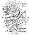
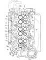
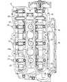
図1〜図6は本発明の一実施形態による船外機用4サイクルエンジンの燃料供給装置を説明するための図であり、図1は本実施形態の燃料供給装置が配設されたエンジンの側面図、図2はその断面平面図、図3はシリンダヘッドのシリンダブロック側から見た底面図、図4はシリンダヘッドの側面図、図5はシリンダヘッドのヘッドカバー側から見た平面図、図6はベーパセパレータタンク周りの一部断面側面図である。なお、本実施形態における前,後、左,右とは、船体前後方向前側に向いた状態での前,後、左,右を意味する。
【0008】
図において、1は船外機用4サイクルV型6気筒エンジンであり、該船外機は船尾に、クランク軸8が縦向きとなる航走時状態と略横向きとなる格納時位置との間で揺動可能に搭載される。該エンジン1のシリンダブロック2の前側合面aにはクランクケース3が接続され、後側合面bにはシリンダヘッド4が接続され、該シリンダヘッド4のカム室側開口はヘッドカバー5で覆われている。該エンジンは上記航走時状態では、上記ヘッドカバー5,及びシリンダヘッド4が船体前後方向後向きとなる。
【0009】
ここで上記ヘッドカバー5は横断面大略カップ状でクランク軸8方向に延びる吸気側カバー5aと排気側カバー5bとを長手方向途中部及び下端部で一体的に結合したアルミニウム合金鋳造製のものである。
【0010】
上記シリンダブロック2には、左,右気筒(シリンダボア)2a,2bが、これらの軸線が挟み角60度のVバンクをなすように、かつクランク軸8方向に偏位するように形成されている。該左,右気筒2a,2bはそれぞれ3組ずつ形成されており、該3組の左気筒2a群からなる左シリンダブロック2,左シリンダヘッド4,及び左ヘッドカバー5により左バンクAが、また上記3組の右気筒2b群からなる右シリンダブロック2,右シリンダヘッド4,及び右ヘッドカバー5により右バンクBがそれぞれ形成されている。
【0011】
ここで、本実施形態では右バンクB側の右気筒2bが左バンクA側の左気筒2aより上側に偏位している。また上記各気筒2a,2bに摺動自在に挿入配置されたピストン6はコンロッド7でクランク軸8のクランクピン8aに連結されている。
【0012】
上記シリンダヘッド4のシリンダブロック2側合面には上記気筒,及びピストンとで燃焼室を形成する燃焼凹部4aが凹設されている。該燃焼凹部4aには気筒当たり2つずつの吸気弁開口4b,4b及びこれより小径の排気弁開口4c,4cが形成されている。また該燃焼凹部4aの気筒中心部には点火プラグ9が螺挿され、電極9aが該燃焼凹部4a内に露出している。
【0013】
上記排気弁開口4c,4cは排気ポート4dにより上記Vバンク内に導出され、各バンク毎の排気マニホールド4eに集合するように連通されており、排気ガスは該排気マニホールド4eによりエンジン下方の水中に排出される。なお、4fは排気マニホールド4eの背面側に水冷ジャケット4gを形成するジャケットカバーである。
【0014】
上記吸気弁開口4b,4bは、それぞれ独立の吸気ポート4h,4hによりシリンダヘッド4の側壁に導出されており、該各吸気ポート4h,4hの外部接続開口4i,4iには吸気マニホールド10の分岐部10a,10aが接続されている。上記吸気マニホールド10は上記各分岐部10a,10aに分岐される二股状の3つの合流部10bを一体形成してなるアルミニウム合金鋳物製のものである。
【0015】
上記吸気マニホールド10の各合流部10bの上流側にはスロットルバルブ(図示せず)を内蔵するスロットルボディ11が接続され、該スロットルボディの上流側には所定の容積を有する吸気サイレンサ12が接続されている。
【0016】
このようにして、図2に示すように、上記吸気ポート4h及び吸気マニホールド10の各分岐部10aにより、上記吸気弁開口4aから略円弧状をなすように船体前方に屈曲する屈曲部13aが形成され、さらに該屈曲部13aに続いてスロットルボディ11及び吸気サイレンサ12により前方に延びる吸気通路13が構成されている。
【0017】
上記吸気通路13の隣接する屈曲部13a同士の間に、上記燃焼室内に燃料を噴射供給する燃料噴射弁14が挿入配設されている。詳細には、上記シリンダヘッド4の各気筒における上記屈曲部13aの一部を構成する上,下の吸気ポート4h,4h間部分に弁取付穴4jが形成されており、該弁取付穴4jの底面から上記燃焼凹部4aに連通するようにノズル孔4kが貫通形成されている。
【0018】
上記弁取付孔4jに上記燃料噴射弁14が挿入配置されている。クランク軸8方向に見たとき、該燃料噴射弁14は、これの軸線cが気筒軸線dと斜めに交叉するように上記屈曲部13a同士の中心にて斜め外方に延びるように配置されている。該燃料噴射弁14の噴射ノズル14aは上記燃焼凹部4aの内面に臨んでおり、また燃料導入口14bは上記屈曲部13aの外方に位置している。
【0019】
また筒状の燃料供給レール15がクランク軸8方向に向けて、かつ上記屈曲部13aの外方に位置するよう配設されている。該燃料供給レール15は、図2に示されているように、船外機特有の吸気通路形状である前方屈曲部13aとシリンダヘッド4の側壁とで形成された凹部D内を通るように配置されている。
【0020】
上記燃料供給レール15には3つの燃料供給口15aが分岐するように形成されており、該各燃料供給口15aは上記燃料噴射弁14の各燃料導入口14bに嵌合接続されている。
【0021】
上記排気弁開口4c,吸気弁開口4bを開閉する排気弁16,吸気弁17はその軸線が上記気筒軸dと斜めに交叉するように配置されており、該排気弁16,17はクランク軸8と平行に配置された排気カム軸18,吸気カム軸19により開閉駆動される。上記両カム軸18,19はシリンダヘッド4のカバー側合面に配置され、カムキャップ20によって回転自在に支持されている。
【0022】
そして左バンクA側の左ヘッドカバー5の吸気側カバー5aの下部に燃料噴射用の高圧ポンプ21が外側から内部に向けて挿入され、該吸気側カバー5aの取付座5cに固定されている。該高圧ポンプ21の先端のプランジャ駆動ピン21aは吸気カム軸19のポンプ駆動カムノーズ19aに摺接している。
【0023】
上記高圧ポンプ21は、クランク軸8方向、即ち吸気カム軸19方向に見たときそのポンプ軸線eが該吸気カム軸19の軸線fに直交し、かつ該エンジン1のVバンク中心側に向かって傾斜するように配置されている。
【0024】
ここで上記高圧ポンプ19,及び燃料噴射弁14はこれらの軸線e,及びcが気筒軸線dとで三角形を形成するように配置されている。そしてこの場合に上記高圧ポンプ19をこれの軸線eと気筒軸線dとのなす角度ができるだけ大きくなるようVバンク中心側に傾斜させることが望ましい。このようにすることにより、高圧ポンプ19のエンジン後方への突出量を少なくできる。
【0025】
また上記右バンクB側のヘッドカバー5の吸気側カバー5aの上端部に気液分離室(図示せず)が形成されている。本実施形態では、右バンクB側が左バンクA側より高所に位置するように偏位しており、従って上記気液分離室はカム軸配置室全体で見た時最も高所に位置している。このように構成したので、ブローバイガス中のオイルミストをより確実に分離でき、オイルミストが大気に排出されるのを防止できる。
【0026】
上記燃料噴射弁14に燃料を供給するための燃料供給装置22は、主として図1,図6に示すように、以下のように構成されている。
【0027】
上記エンジン1の側壁前部に燃料フィルタ23,燃料供給用低圧ポンプ24,ベーパセパレータタンク25が取り付けられており、これらは燃料供給用低圧ホース26で連通されている。
【0028】
上記燃料供給装置22では、船体側に搭載された燃料タンク(図示せず)内の燃料が上記低圧ポンプ24により上記低圧ホース26,燃料フィルタ23を介して上記ベーパセパレータタンク25に供給される。この低圧ポンプ24の吐出口24aから吐出された燃料の余剰分はリターンホース35により低圧ポンプ24の吸込口24a側に戻される。
【0029】
そして上記ベーパセパレータタンク25内の燃料が内蔵式の低圧ポンプ(図示せず)により燃料ホース27を介して上記高圧ポンプ21に供給され、該高圧ポンプ21で昇圧された燃料が高圧ホース28及び左,右分岐ホース28a,28bを介して上記左,右の燃料レール15,15の下端部に供給される。そして、上記燃料噴射弁14の噴射ノズル14aが開とされている期間、燃料が燃焼室内に直接噴射供給される。
【0030】
また上記高圧ポンプ21は吐出圧及び流量を調整するための第1,第2戻り口21b,21cを備えている。該第1戻り口21bは、該エンジン1の左側壁に沿うように配索された第1戻りホース30により上記ベーパセパレータタンク25に連通接続されている。具体的には、上記第1戻りホース30は、上記第1戻り口21bから上方に立ち上がり、エンジン上部を前方に延び、上記ベーパセパーレタタンク25及び低圧ポンプ24の前側を下方に延び、さらに該エンジン1の下端付近を通って上記ベーパセパレータタンク25に接続されている。
【0031】
また上記第1戻りホース30の下流側途中には冷却器36が介設されている。この冷却器36は、高圧ポンプ21からの戻り燃料を冷却するためのものであり、ベーパセパレータタンク25の前側下方に配設されている。
【0032】
上記冷却器36の上端には冷却水を導入する冷却水導入ホース36aが接続され、下端には冷却水排出ホース36bが接続されている。そして上記第1戻りホース30は冷却器36内を挿通しており、該冷却器36内を流通する際に戻り燃料が冷却される。
【0033】
また上記燃料供給レール15の上端部には圧力調整用のレギュレータ31が接続されており、該レギュレータ31の戻り通路(図示せず)は上記第1戻りホース30の途中に連通接続されている。上記燃料供給レール15内の圧力が設定値を越えると上記レギュレータ31が開き、余分の燃料が上記第1戻りホース30を介して上記同様に冷却器36により冷却されてベーパセパレータタンク25に戻される。
【0034】
また上記第2戻り口21cは該エンジン1の左側壁に沿うように配索された第2戻りホース29により上記ベーパセパレータタンク25に連通接続されている。具体的には、上記第2戻りホース20は、上記第2戻り口21cからエンジン下部を通って上記吸気通路13の外側を斜め後上方に立ち上がり、上記ベーパセパレータタンク25に連通接続されている。
【0035】
そして上記ベーパセパレータタンク25の上部にはキャニスタ40が一体に取付け固定されている。このキャニスタ40は、上記ベーパセパレータタンク25に連通接続されたケース40a内に活性炭等の吸着活性剤41を充填してなるものであり、該吸着活性材41の上下両端面にはベーパが挿通可能な網板42が配設されている。上記ペーパセパレータタンク25内のベーパはキャニスタ40内に進入し、ここでベーパ中の燃料が吸着される。なお、燃料が吸着分離された空気は排出管43を通ってカウル内に放出されるようになっている。
【0036】
また上記低圧ホース26,燃料ホース27,及び第2戻りホース29はキャニスタ40の上壁に植設された接続パイプ26a,27a,29aに接続されており、これらの接続パイプ26a,27a,29aは上記キャニスタ40を貫通してベーパセパレータタンク25内に延びており、燃料が吸着活性剤41に直接接触することはない。
【0037】
次に本実施形態の動作及び作用効果を説明する。
本実施形態の燃料供給装置22によれば、燃料タンクの燃料が供給されるベーパセパレータタンク25に高圧ポンプ21からの余剰燃料を戻すとともに、該ベーパセパレータタンク25の上部にキャニスタ40を接続し、該キャニスタ40によりベーパセパレータタンク25内のベーパから燃料を吸着分離し、該分離された燃料をベーパセパレータタンク25に戻すとともに、空気を排出管43により外部に放出したので、カウル内温度の上昇によって多量ベーパが発生しても、該ベーパはキャニスタ40により燃料が吸着分離されることから、残りの空気を外部に放出でき、吸気系に供給する必要はない。その結果、多量のベーパが吸気系に吸引されることによるエンジンの低速回転不調、燃費及び排ガス性状の悪化といった問題を回避できる。
【0038】
本実施形態エンジン1では、船外機特有の吸気通路形状を利用して燃料噴射弁14及び燃料供給レール15を配置でき、これらの部品の配置によってエンジン幅が拡大されることはなく、直接燃料噴射方式をエンジン搭載スペースをほとんど拡大することなく実現できる。
【0039】
即ち、燃料噴射弁14を、吸気通路13の隣接する前方屈曲部13a同士の間に、より具体的には各気筒の分岐部10a,10a間から吸気ポート4h,4h間に挿入するように配設し、燃料料導入口14bを上記屈曲部13aの外側に位置させ、該燃料導入口14bに上記屈曲部13aの外方に位置するよう配設した燃料供給レール15の供給口15aを嵌合接続したので、該燃料供給レール15を吸気通路13の前方屈曲部13aとシリンダヘッド側壁とで形成される凹部D内に位置させることができ、エンジン幅の拡大を回避できる。
【0040】
また、気筒が高所側に偏位している右バンク(高所側バンク)Bの吸気側カム室5aの上端部に気液分離室を設け、気筒が低所側に偏位している左バンク(低所側バンク)Aの吸気カム軸19により燃料噴射用高圧ポンプ21を駆動したので、気液分離室を設けながら高圧ポンプ21の配置スペースを無理なく確保できる。
【0041】
さらにまた上記高圧ポンプ21を、バンク外側に配置された吸気カム軸19で駆動されるように吸気側ヘッドカバー5aに取り付け、かつバンク中心側(右バンク側)に傾斜させたので、高圧ポンプ21がエンジン幅方向に突出することはなく、またエンジン後方への突出を抑制でき、エンジン搭載スペースの拡大を回避できる。
【0042】
なお、上記実施形態では直噴エンジンの場合を説明したが本発明の適用範囲はこれに限定されるものではなく、吸気通路の途中に燃料を噴射するようにしたエンジンにも適用できる。
【図面の簡単な説明】
【図1】本発明の一実施形態による燃料供給装置が配設された船外機用V型エンジンの側面図である。
【図2】上記エンジンの断面平面図である。
【図3】上記エンジンのシリンダヘッドの底面図である。
【図4】上記エンジンのシリンダヘッドのシリンダブロック側から見た図である。
【図5】上記エンジンのシリンダヘッドのヘッドカバー側から見た図である。
【図6】上記燃料供給装置のベーパセパレータタンク周りの一部断面側面図である。
【符号の説明】
1 4サイクルV型エンジン
14 燃料噴射弁
21 燃料噴射用高圧燃料ポンプ
22 燃料供給装置
24 低圧燃料ポンプ
25 ベーパセパレータタンク
40 キャニスタ[0001]
[Industrial application fields]
The present invention relates to a fuel supply device for a four-cycle engine for an outboard motor, and more particularly to a vapor (air containing fuel) in a so-called four-cycle engine fuel supply device configured to inject and supply fuel into a combustion chamber or an intake pipe. The improvement of the processing method.
[0002]
[Prior art]
In general, an outboard motor has an engine housed in a cowl and is mounted on the hull with the crankshaft of the engine facing the vertical direction and the cylinder head facing the rear side in the longitudinal direction of the hull. . As this type of outboard engine, it is considered to adopt a four-cycle direct injection engine configured to directly inject and supply fuel into the combustion chamber.
[0003]
[Problems to be solved by the invention]
By the way, the fuel supply device for the
[0004]
The present invention has been made in view of the above-described conventional problems, and even when the amount of vapor generated is large, four cycles for an outboard motor that can avoid the problems of low-speed rotation failure, fuel consumption, and exhaust gas property deterioration as in the intake air recirculation system. It aims at providing the fuel supply apparatus of an engine.
[0005]
[Means for Solving the Problems]
According to the first aspect of the present invention, the fuel in the main tank disposed on the hull side is supplied to the vapor separator tank disposed in the cowl by the low pressure fuel pump, and the fuel in the vapor separator tank is injected by the high pressure fuel pump. In a fuel supply system for an outboard motor for a four-cycle engine that is supplied to a valve, a canister that adsorbs fuel in a vaporis disposedintegrally with the upper portion of the vapor separator tank, and the canister The fuel is separated from the vapor, the separatedfuel is returned into the vapor separator tank, and the air from which the fuel has been separated is discharged to the outside through a discharge pipe communicating withthe outside of the vapor separator tank. Yes.
[0006]
[Effects of the invention]
According to the present invention, the surplus of fuel that has passed through the high-pressure fuel pump is returned to the vapor separator tank to which the fuel in the main tank is supplied, and the canister for adsorbing fuel in the vapor is provided in the vapor separator tank. Since the fuel is adsorbed and separated from the vapor in the separator tank, the air from which the fuel has been separated can be discharged to the outside, and even if a large amount of vapor is generated due to the high temperature in the cowl, the vapor is taken into the intake system. Therefore, it is not necessary to supply the fuel, and therefore problems such as poor low-speed rotation of the engine due to a large amount of vapor being sucked into the intake system, deterioration of fuel consumption and exhaust gas properties can be avoided.
[0007]
DETAILED DESCRIPTION OF THE INVENTION
Hereinafter, embodiments of the present invention will be described with reference to the accompanying drawings.
1 to 6 are views for explaining a fuel supply device for an outboard motor for a four-cycle engine according to an embodiment of the present invention. FIG. 1 shows an engine in which the fuel supply device of this embodiment is arranged. 2 is a sectional plan view of the cylinder head, FIG. 3 is a bottom view of the cylinder head viewed from the cylinder block side, FIG. 4 is a side view of the cylinder head, and FIG. 5 is a plan view of the cylinder head viewed from the head cover side. 6 is a partial cross-sectional side view around the vapor separator tank. In the present embodiment, front, rear, left, and right mean front, rear, left, and right in a state of facing forward in the hull longitudinal direction.
[0008]
In the figure, reference numeral 1 denotes a 4-cycle V type 6-cylinder engine for an outboard motor. It is mounted so that it can swing. A
[0009]
Here, the
[0010]
In the cylinder block 2, left and right cylinders (cylinder bores) 2a and 2b are formed such that their axis lines form a V bank with a sandwich angle of 60 degrees and are displaced in the direction of the crankshaft 8. . The left and
[0011]
Here, in the present embodiment, the
[0012]
A combustion recess 4a that forms a combustion chamber with the cylinder and the piston is formed in the cylinder block 2 side mating surface of the
[0013]
The
[0014]
The
[0015]
A
[0016]
In this way, as shown in FIG. 2, a
[0017]
A
[0018]
The
[0019]
A cylindrical
[0020]
Three
[0021]
The exhaust valve opening 4c, the exhaust valve 16 that opens and closes the
[0022]
A
[0023]
When viewed in the crankshaft 8 direction, that is, the
[0024]
Here, the
[0025]
Further, a gas-liquid separation chamber (not shown) is formed at the upper end of the
[0026]
The
[0027]
A fuel filter 23, a fuel supply low-
[0028]
In the
[0029]
The fuel in the
[0030]
The high-
[0031]
A cooler 36 is interposed in the middle of the downstream side of the
[0032]
A cooling
[0033]
A pressure adjusting regulator 31 is connected to the upper end of the
[0034]
The
[0035]
A
[0036]
The
[0037]
Next, the operation and effect of this embodiment will be described.
According to the
[0038]
In the engine 1 of the present embodiment, the
[0039]
In other words, the
[0040]
In addition, a gas-liquid separation chamber is provided at the upper end of the intake
[0041]
Furthermore, the high-
[0042]
In addition, although the case of the direct injection engine was demonstrated in the said embodiment, the application range of this invention is not limited to this, It can apply also to the engine which injected the fuel in the middle of the intake passage.
[Brief description of the drawings]
FIG. 1 is a side view of an outboard motor V-type engine provided with a fuel supply device according to an embodiment of the present invention.
FIG. 2 is a cross-sectional plan view of the engine.
FIG. 3 is a bottom view of the cylinder head of the engine.
FIG. 4 is a view of a cylinder head of the engine as viewed from the cylinder block side.
FIG. 5 is a view of a cylinder head of the engine as viewed from the head cover side.
FIG. 6 is a partial cross-sectional side view around a vapor separator tank of the fuel supply device.
[Explanation of symbols]
1 4 cycle
Claims (1)
Translated fromJapaneseベーパ中の燃料を吸着するキャニスタを上記ベーパセパレータタンク内の上部に一体に配置し、該キャニスタによりベーパセパレータタンク内のベーパから燃料を分離し、
該分離された燃料を上記ベーパーセパレータタンク内に戻すとともに、上記燃料が分離された空気を上記ベーパセパレータタンクの外部に連通した排出管により外部に放出した
ことを特徴とする船外機用4サイクルエンジンの燃料供給装置。The fuel in the main tank arranged on the hull side is supplied to the vapor separator tank arranged in the cowl by the low-pressure fuel pump, and the fuel in the vapor separator tank is supplied to the fuel injection valve by the high-pressure fuel pump. In a fuel supply system for an outboard 4-cycle engine,
A canister that adsorbs fuel in the vaporis disposedintegrally with the upper portion in the vapor separator tank, and the fuel is separated from the vapor in the vapor separator tank by the canister,
The outboard characterizedin that the separated fuel is returned into the vapor separator tank, and air from which the fuel has been separated is discharged to the outside through a discharge pipe communicating withthe outside of the vapor separator tank. 4 cycle engine fuel supply device.
Priority Applications (2)
| Application Number | Priority Date | Filing Date | Title |
|---|---|---|---|
| JP2000359493AJP4259744B2 (en) | 2000-11-27 | 2000-11-27 | Fuel supply system for 4-cycle engine for outboard motor |
| US09/994,435US6575145B2 (en) | 2000-11-27 | 2001-11-26 | Fuel supply system for four-cycle outboard motor |
Applications Claiming Priority (1)
| Application Number | Priority Date | Filing Date | Title |
|---|---|---|---|
| JP2000359493AJP4259744B2 (en) | 2000-11-27 | 2000-11-27 | Fuel supply system for 4-cycle engine for outboard motor |
Publications (2)
| Publication Number | Publication Date |
|---|---|
| JP2002161813A JP2002161813A (en) | 2002-06-07 |
| JP4259744B2true JP4259744B2 (en) | 2009-04-30 |
Family
ID=18831249
Family Applications (1)
| Application Number | Title | Priority Date | Filing Date |
|---|---|---|---|
| JP2000359493AExpired - LifetimeJP4259744B2 (en) | 2000-11-27 | 2000-11-27 | Fuel supply system for 4-cycle engine for outboard motor |
Country Status (2)
| Country | Link |
|---|---|
| US (1) | US6575145B2 (en) |
| JP (1) | JP4259744B2 (en) |
Families Citing this family (29)
| Publication number | Priority date | Publication date | Assignee | Title |
|---|---|---|---|---|
| US10569792B2 (en) | 2006-03-20 | 2020-02-25 | General Electric Company | Vehicle control system and method |
| US9733625B2 (en) | 2006-03-20 | 2017-08-15 | General Electric Company | Trip optimization system and method for a train |
| US10308265B2 (en) | 2006-03-20 | 2019-06-04 | Ge Global Sourcing Llc | Vehicle control system and method |
| US6694955B1 (en) | 2002-07-09 | 2004-02-24 | Brunswick Corporation | Marine engine with primary and secondary fuel reservoirs |
| US9950722B2 (en) | 2003-01-06 | 2018-04-24 | General Electric Company | System and method for vehicle control |
| JP2005042706A (en)* | 2003-07-08 | 2005-02-17 | Yamaha Marine Co Ltd | Fuel supply device of outboard motor |
| US6971374B2 (en)* | 2003-07-08 | 2005-12-06 | Yamaha Marine Kabushiki Kaisha | Fuel supply system for outboard motor |
| DE10342387B3 (en) | 2003-09-13 | 2005-05-25 | Man B & W Diesel Ag | Change-over system for change over of injection engine, has high pressure pump with common rail arrangement, and parallel longitudinal support arranged for cylinder-series, in which high pressure accumulator of arrangement is attached |
| US7410022B1 (en)* | 2004-05-20 | 2008-08-12 | Polaris Industries Inc. | Fuel pickup return line and separator |
| US7013878B1 (en) | 2004-06-03 | 2006-03-21 | Walbro Engine Management, L.L.C. | Fuel vapor separator |
| US7234449B2 (en)* | 2005-07-14 | 2007-06-26 | General Electric Company | Common fuel rail fuel system for locomotive engine |
| JP4636327B2 (en)* | 2005-10-31 | 2011-02-23 | スズキ株式会社 | Evaporative fuel treatment system for outboard motor |
| JP4561599B2 (en)* | 2005-11-07 | 2010-10-13 | スズキ株式会社 | Evaporative fuel treatment system for portable fuel tank for outboard motor |
| US9828010B2 (en) | 2006-03-20 | 2017-11-28 | General Electric Company | System, method and computer software code for determining a mission plan for a powered system using signal aspect information |
| US9156477B2 (en) | 2006-03-20 | 2015-10-13 | General Electric Company | Control system and method for remotely isolating powered units in a vehicle system |
| US9689681B2 (en) | 2014-08-12 | 2017-06-27 | General Electric Company | System and method for vehicle operation |
| JP4592633B2 (en)* | 2006-03-31 | 2010-12-01 | 本田技研工業株式会社 | Internal combustion engine fuel pump |
| US7395814B1 (en) | 2006-09-11 | 2008-07-08 | Brunswick Corporation | Electronic voltage regulation for a marine returnless fuel system |
| US7543573B2 (en)* | 2007-05-31 | 2009-06-09 | Gm Global Technology Operations, Inc. | Fuel recovery system for internal combustion engines |
| US7630823B2 (en)* | 2007-09-20 | 2009-12-08 | General Electric Company | System and method for controlling the fuel injection event in an internal combustion engine |
| US7832380B1 (en) | 2009-01-28 | 2010-11-16 | Brunswick Corporation | Marine fuel system with an ullage control device |
| US9834237B2 (en) | 2012-11-21 | 2017-12-05 | General Electric Company | Route examining system and method |
| US8166955B2 (en)* | 2009-08-27 | 2012-05-01 | Federal Mogul Corporation | Fuel vapor separator with evaporative emissions chamber and marine fuel system and engine therewith |
| JP5899935B2 (en)* | 2012-01-10 | 2016-04-06 | スズキ株式会社 | Outboard motor fuel supply system |
| US9682716B2 (en) | 2012-11-21 | 2017-06-20 | General Electric Company | Route examining system and method |
| US9669851B2 (en) | 2012-11-21 | 2017-06-06 | General Electric Company | Route examination system and method |
| DE102013210973A1 (en)* | 2013-06-12 | 2014-12-18 | Mahle International Gmbh | Fuel Supply System |
| JP7035578B2 (en)* | 2018-02-02 | 2022-03-15 | マツダ株式会社 | Engine fuel supply |
| JP2020101096A (en)* | 2018-12-20 | 2020-07-02 | ヤマハ発動機株式会社 | Outboard engine |
Family Cites Families (44)
| Publication number | Priority date | Publication date | Assignee | Title |
|---|---|---|---|---|
| JPH10205347A (en) | 1996-11-20 | 1998-08-04 | Sanshin Ind Co Ltd | Outboard motor |
| US5249557A (en) | 1991-02-18 | 1993-10-05 | Sanshin Kogyo Kabushiki Kaisha | Fuel injection system for two cycle engine |
| US5271358A (en) | 1991-03-20 | 1993-12-21 | Sanshin Kogyo Kabushiki Kaisha | Fuel injection system for engine |
| JPH04321737A (en) | 1991-04-22 | 1992-11-11 | Sanshin Ind Co Ltd | Fuel injection device for internal combustion engine |
| US5309885A (en)* | 1992-02-13 | 1994-05-10 | Outboard Marine Corporation | Marine propulsion device including a fuel injected, four-cycle internal combustion engine |
| JPH08121278A (en)* | 1994-10-19 | 1996-05-14 | Sanshin Ind Co Ltd | Fuel supplying device for engine |
| JPH08261003A (en)* | 1995-03-27 | 1996-10-08 | Sanshin Ind Co Ltd | Generator arrangement structure for outboard engine |
| US5755606A (en) | 1995-08-03 | 1998-05-26 | Sanshin Kogyo Kabushiki Kaisha | Four-cam outboard motor |
| US5752866A (en) | 1995-08-03 | 1998-05-19 | Sanshin Kogyo Kabushiki Kaisha | Lubrication and crankcase ventilating system for four-cycle outboard motor |
| US5778847A (en) | 1995-08-03 | 1998-07-14 | Sanshin Kogyo Kabushiki Kaisha | Four cycle outboard motor |
| JPH0949411A (en) | 1995-08-07 | 1997-02-18 | Sanshin Ind Co Ltd | Four-cycle engine for outboard engine |
| US5647331A (en)* | 1995-09-12 | 1997-07-15 | Walbro Corporation | Liquid cooled fuel pump and vapor separator |
| JPH0988623A (en) | 1995-09-29 | 1997-03-31 | Sanshin Ind Co Ltd | In-line multiple cylinder engine for outboard motor |
| JP3607386B2 (en)* | 1995-11-27 | 2005-01-05 | ヤマハマリン株式会社 | Outboard motor fuel supply system |
| JPH09189235A (en) | 1995-12-30 | 1997-07-22 | Sanshin Ind Co Ltd | Engine device of outboard engine |
| JPH09250415A (en) | 1996-03-18 | 1997-09-22 | Sanshin Ind Co Ltd | Fuel pump disposition structure for outboard motor |
| JPH09280140A (en) | 1996-04-12 | 1997-10-28 | Sanshin Ind Co Ltd | Fuel injector arranging structure for outboard engine |
| JP3608637B2 (en) | 1996-04-12 | 2005-01-12 | ヤマハマリン株式会社 | Outboard motor |
| JPH09280141A (en) | 1996-04-12 | 1997-10-28 | Sanshin Ind Co Ltd | Outboard engine of fuel injection type |
| US6286476B1 (en) | 1996-04-30 | 2001-09-11 | Sanshin Kogyo Kabushiki Kaisha | Engine lubricating system |
| US5941205A (en) | 1996-06-10 | 1999-08-24 | Sanshin Kogyo Kabushiki Kaisha | Intake system for a four-cycle engine powering an outboard motor |
| JPH1061446A (en) | 1996-08-26 | 1998-03-03 | Sanshin Ind Co Ltd | Intake structure of outboard motor |
| JP3883239B2 (en) | 1996-10-21 | 2007-02-21 | ヤマハマリン株式会社 | Fuel supply system for outboard engine |
| JPH10159697A (en) | 1996-11-27 | 1998-06-16 | Sanshin Ind Co Ltd | Flywheel structure of engine |
| JP3879943B2 (en) | 1996-11-28 | 2007-02-14 | ヤマハマリン株式会社 | Outboard motor |
| JPH10220312A (en) | 1997-02-05 | 1998-08-18 | Sanshin Ind Co Ltd | Arrangement structure of intake pipe for outboard motor and auxiliary machine |
| JPH1150855A (en) | 1997-08-06 | 1999-02-23 | Sanshin Ind Co Ltd | Engine device for outboard engine |
| US6220217B1 (en) | 1997-08-11 | 2001-04-24 | Sanshin Kogyo Kabushiki Kaisha | Fuel supply system for direct injected system for engines |
| US6321711B1 (en) | 1997-08-11 | 2001-11-27 | Sanshin Kogyo Kabushiki Kaisha | Fuel supply system for a direct injected outboard engine |
| US6099374A (en) | 1997-08-14 | 2000-08-08 | Sanshin Kogyo Kabushiki Kaisha | Lubrication and oil drain system for 4 cycle outboard motor |
| JP3942698B2 (en) | 1997-08-14 | 2007-07-11 | ヤマハマリン株式会社 | Blow-by gas reduction device for DOHC engine for outboard motor |
| JP3897197B2 (en) | 1997-09-12 | 2007-03-22 | ヤマハマリン株式会社 | Blow-by gas reduction structure for outboard engine |
| JP3969549B2 (en) | 1997-09-12 | 2007-09-05 | ヤマハマリン株式会社 | Intake passage structure for outboard engine |
| JP3900389B2 (en) | 1997-09-12 | 2007-04-04 | ヤマハマリン株式会社 | Intake passage mounting structure for outboard engine |
| US6213096B1 (en) | 1998-03-25 | 2001-04-10 | Sanshin Kogyo Kabushiki Kaisha | Fuel supply for direct injected engine |
| JP3963292B2 (en) | 1998-04-24 | 2007-08-22 | ヤマハマリン株式会社 | Outboard engine |
| DE69927444T2 (en) | 1998-07-17 | 2006-03-16 | Yamaha Marine Kabushiki Kaisha, Hamamatsu | Internal combustion engine |
| JP2000186642A (en) | 1998-12-22 | 2000-07-04 | Sanshin Ind Co Ltd | Intake device of outboard motor |
| US6276327B1 (en) | 1999-02-01 | 2001-08-21 | Sanshin Kogyo Kabushiki Kaisha | Engine layout for outboard motor |
| US6296536B1 (en) | 1999-04-27 | 2001-10-02 | Sanshin Kogyo Kabushiki Kaisha | Cowling assembly for outboard motor |
| JP2000310118A (en) | 1999-04-27 | 2000-11-07 | Sanshin Ind Co Ltd | Silencer device for outboard motor |
| JP2001041018A (en) | 1999-07-30 | 2001-02-13 | Sanshin Ind Co Ltd | Crankshaft bearing mechanism of engine |
| JP2001098950A (en) | 1999-09-29 | 2001-04-10 | Sanshin Ind Co Ltd | Outboard engine |
| US6422255B1 (en)* | 2000-08-03 | 2002-07-23 | Bombardier Motor Corporation Of America | Multi-function valve having a movable seat and needle |
- 2000
- 2000-11-27JPJP2000359493Apatent/JP4259744B2/ennot_activeExpired - Lifetime
- 2001
- 2001-11-26USUS09/994,435patent/US6575145B2/ennot_activeExpired - Fee Related
Also Published As
| Publication number | Publication date |
|---|---|
| US20020062819A1 (en) | 2002-05-30 |
| JP2002161813A (en) | 2002-06-07 |
| US6575145B2 (en) | 2003-06-10 |
Similar Documents
| Publication | Publication Date | Title |
|---|---|---|
| JP4259744B2 (en) | Fuel supply system for 4-cycle engine for outboard motor | |
| JP4391003B2 (en) | Outboard motor | |
| US5235944A (en) | Engine lubricating system | |
| JP4768560B2 (en) | Water-cooled engine | |
| JPH11280540A (en) | Cylinder fuel injection engine | |
| JP3720402B2 (en) | Fuel-injection outboard motor | |
| JP2000073853A (en) | Fuel cylinder injection type engine | |
| US6321711B1 (en) | Fuel supply system for a direct injected outboard engine | |
| US6752114B2 (en) | Four-cycle engine for outboard motor | |
| US5673655A (en) | V-type engine | |
| US6863036B2 (en) | Lubrication system for two-cycle engine | |
| US6142116A (en) | Internal combustion engine with cylinder head having unique head bolt mounting and port arrangement | |
| US11053898B2 (en) | Saddle riding vehicle | |
| US6478002B1 (en) | Engine for watercraft | |
| US7444974B2 (en) | Internal combustion engine intake device | |
| US6662786B2 (en) | Vapor separator for outboard motor | |
| JP4188467B2 (en) | In-cylinder injection 4-cycle engine for outboard motors | |
| JP3621147B2 (en) | Operation control device for fuel injection type 2-cycle engine for outboard motor | |
| US6318331B1 (en) | Lubrication system for direct injected engine | |
| JP3324913B2 (en) | V-type multi-cylinder engine intake system | |
| JP2002147306A (en) | Fuel supply system for four-cycle engine for outboard motor | |
| JP2001295714A (en) | Fuel pipe structure of engine | |
| JP2013124595A (en) | Outboard motor, and watercraft having the same | |
| JP2001336425A (en) | Outboard motor mounted with four-cycles v-type engine | |
| JPH11270426A (en) | Cylinder fuel injection type engine |
Legal Events
| Date | Code | Title | Description |
|---|---|---|---|
| A621 | Written request for application examination | Free format text:JAPANESE INTERMEDIATE CODE: A621 Effective date:20071009 | |
| A131 | Notification of reasons for refusal | Free format text:JAPANESE INTERMEDIATE CODE: A131 Effective date:20081028 | |
| A521 | Written amendment | Free format text:JAPANESE INTERMEDIATE CODE: A523 Effective date:20081218 | |
| A711 | Notification of change in applicant | Free format text:JAPANESE INTERMEDIATE CODE: A712 Effective date:20090116 | |
| TRDD | Decision of grant or rejection written | ||
| A01 | Written decision to grant a patent or to grant a registration (utility model) | Free format text:JAPANESE INTERMEDIATE CODE: A01 Effective date:20090127 | |
| A01 | Written decision to grant a patent or to grant a registration (utility model) | Free format text:JAPANESE INTERMEDIATE CODE: A01 | |
| A61 | First payment of annual fees (during grant procedure) | Free format text:JAPANESE INTERMEDIATE CODE: A61 Effective date:20090203 | |
| FPAY | Renewal fee payment (event date is renewal date of database) | Free format text:PAYMENT UNTIL: 20120220 Year of fee payment:3 | |
| R150 | Certificate of patent or registration of utility model | Ref document number:4259744 Country of ref document:JP Free format text:JAPANESE INTERMEDIATE CODE: R150 Free format text:JAPANESE INTERMEDIATE CODE: R150 | |
| FPAY | Renewal fee payment (event date is renewal date of database) | Free format text:PAYMENT UNTIL: 20130220 Year of fee payment:4 | |
| R250 | Receipt of annual fees | Free format text:JAPANESE INTERMEDIATE CODE: R250 | |
| FPAY | Renewal fee payment (event date is renewal date of database) | Free format text:PAYMENT UNTIL: 20130220 Year of fee payment:4 | |
| FPAY | Renewal fee payment (event date is renewal date of database) | Free format text:PAYMENT UNTIL: 20140220 Year of fee payment:5 | |
| R250 | Receipt of annual fees | Free format text:JAPANESE INTERMEDIATE CODE: R250 | |
| R250 | Receipt of annual fees | Free format text:JAPANESE INTERMEDIATE CODE: R250 | |
| R250 | Receipt of annual fees | Free format text:JAPANESE INTERMEDIATE CODE: R250 | |
| R250 | Receipt of annual fees | Free format text:JAPANESE INTERMEDIATE CODE: R250 | |
| R250 | Receipt of annual fees | Free format text:JAPANESE INTERMEDIATE CODE: R250 | |
| R250 | Receipt of annual fees | Free format text:JAPANESE INTERMEDIATE CODE: R250 | |
| R250 | Receipt of annual fees | Free format text:JAPANESE INTERMEDIATE CODE: R250 | |
| R250 | Receipt of annual fees | Free format text:JAPANESE INTERMEDIATE CODE: R250 | |
| EXPY | Cancellation because of completion of term |