JP4258069B2 - Variable capacity scroll compressor and refrigeration cycle for vehicle - Google Patents
Variable capacity scroll compressor and refrigeration cycle for vehicleDownload PDFInfo
- Publication number
- JP4258069B2 JP4258069B2JP19479499AJP19479499AJP4258069B2JP 4258069 B2JP4258069 B2JP 4258069B2JP 19479499 AJP19479499 AJP 19479499AJP 19479499 AJP19479499 AJP 19479499AJP 4258069 B2JP4258069 B2JP 4258069B2
- Authority
- JP
- Japan
- Prior art keywords
- valve body
- pressure
- stopper
- discharge
- movable direction
- Prior art date
- Legal status (The legal status is an assumption and is not a legal conclusion. Google has not performed a legal analysis and makes no representation as to the accuracy of the status listed.)
- Expired - Fee Related
Links
- 238000005057refrigerationMethods0.000titleclaimsdescription11
- 230000006835compressionEffects0.000claimsdescription41
- 238000007906compressionMethods0.000claimsdescription41
- 230000007246mechanismEffects0.000claimsdescription35
- 239000003507refrigerantSubstances0.000claimsdescription35
- 238000006073displacement reactionMethods0.000claimsdescription14
- 239000012530fluidSubstances0.000claimsdescription9
- 230000010349pulsationEffects0.000claimsdescription7
- 238000001514detection methodMethods0.000claimsdescription5
- 238000001816coolingMethods0.000claims1
- 230000001105regulatory effectEffects0.000claims1
- 230000001133accelerationEffects0.000description15
- 239000000446fuelSubstances0.000description14
- 238000006243chemical reactionMethods0.000description4
- 230000004044responseEffects0.000description4
- 230000009471actionEffects0.000description3
- 238000004378air conditioningMethods0.000description3
- 230000008859changeEffects0.000description3
- 230000009194climbingEffects0.000description3
- 230000005540biological transmissionEffects0.000description2
- 230000003247decreasing effectEffects0.000description2
- 238000010586diagramMethods0.000description2
- 238000009499grossingMethods0.000description2
- 230000004048modificationEffects0.000description2
- 238000012986modificationMethods0.000description2
- 238000005096rolling processMethods0.000description2
- 235000014676Phragmites communisNutrition0.000description1
- 238000010438heat treatmentMethods0.000description1
- 239000007791liquid phaseSubstances0.000description1
- 239000002184metalSubstances0.000description1
- 230000002265preventionEffects0.000description1
- 239000011347resinSubstances0.000description1
- 229920005989resinPolymers0.000description1
- 238000012216screeningMethods0.000description1
- 230000035939shockEffects0.000description1
Images


Landscapes
- Rotary Pumps (AREA)
- Applications Or Details Of Rotary Compressors (AREA)
Description
Translated fromJapanese【0001】
【発明の属する技術分野】
本発明は、可変容量スクロール型圧縮機に関するもので、車両用冷凍サイクルの圧縮機に適用して有効である。
【0002】
【従来の技術】
冷凍サイクル用の可変容量スクロール型圧縮機として、例えば特開平9−296787号公報に記載の発明では、コイルバネの弾性力と吸入圧との力の釣り合いにより、圧縮行程中の作動室と吸入側とを連通させるバイパス孔を開閉するスプール弁を開閉作動させている。
【0003】
しかし、上記公報に記載の発明では、コイルバネの弾性力と吸入圧との力の釣り合いによりバイパス孔を開閉するので、冷凍サイクルの熱負荷(蒸発器内圧力)に応じてバイパス孔が開閉することとなる。
【0004】
ところで、車両用冷凍サイクルの圧縮機は、走行用エンジン(以下、エンジンと略す。)から動力を得て稼働するので、登坂時や加速時等のエンジンの負荷が大きいときには、圧縮機の吐出容量を減少させる等してエンジンの負荷を軽減することが加速性能及び燃料消費率(車両燃費)の向上を図る上で望ましい。
【0005】
これに対して、上記公報に記載の発明では、コイルバネの弾性力と吸入圧との力の釣り合いにより、圧縮行程中の作動室と吸入側とを連通させるバイパス孔を開閉するので、エンジンの負荷に応じて吐出容量を変化させることができず、エンジンの適正制御ができないため、加速性能及び車両燃費の向上を図ることが事実上できない。
【0006】
そして、このような要望に対して、例えば特開平2−249717号公報に記載の可変容量斜板型圧縮機では、斜板室内の圧力をエンジン負荷に基づいて制御することにより、斜板の傾斜角を変化させて吐出容量を変化させている。
【0007】
【発明が解決しようとする課題】
ところで、発明者等は、特開平2−249717号公報に記載の発明のごとく、エンジン負荷に応じて斜板室内の圧力を制御したところ、エンジン負荷の変動に対し迅速に傾斜角(吐出容量)が変化しなく、車両燃費を十分に向上させることができなかった。
【0008】
そこで、エンジン負荷の変動に対し迅速に傾斜角(吐出容量)が変化しない原因を調査したところ、以下の点が判明した。
【0009】
すなわち、特開平2−249717号公報に記載の発明では、圧縮反力と斜板室内の圧力との釣り合いにより斜板の傾斜角を制御しているが、圧縮反力は吐出圧に連動して変化するものであり、また、斜板室内の圧力は、吸入圧及び吐出圧を電磁弁等の弁手段にて調節して斜板室に導入することにより制御している。
【0010】
ここで、吸入圧及び吐出圧の両圧力は、冷凍サイクルの熱負荷により変動するものであるので、エンジン負荷に応じて弁手段を制御しても、実際に斜板に作用する力(圧縮反力及び斜板室内の圧力)は、冷凍サイクルの熱負荷の影響を強く受ける。したがって、エンジン負荷に応じて弁手段を制御しても、エンジン負荷の変動に対して迅速に傾斜角(吐出容量)を変化させることができない。
【0011】
また、吐出容量を最大容量と最小容量との2段に分けて制御する程度では、加速性能の向上を図ることができるものの、吐出冷媒流量が減少するので、冷凍能力が低下してしまう。
【0012】
本発明は、上記点に鑑み、例えばエンジン負荷の変動に対して迅速に吐出容量を変化させる等、使用状況に応じて必要な吐出容量に制御することができる圧縮機を提供することを目的とする。
【0013】
【課題を解決するための手段】
本発明は、上記目的を達成するために、請求項1に記載の発明では、固定スクロール(104)及び旋回スクロール(105)を有し、旋回スクロール(105)を固定スクロール(104)に対して旋回させることにより、流体を吸入圧縮する作動室(Vc)を拡大縮小させる圧縮機構(Cp)、圧縮行程中の作動室(Vc)のうち少なくとも2種類の状態の作動室(Vc)と圧縮機構(Cp)の吸入側とを連通させる第1、第2バイパス孔(114a、114b)、並びに、第1、第2バイパス孔(114a、114b)を開閉する弁体(116)を備える可変容量スクロール型圧縮機であって、弁体(116)の可動方向一端側から、弁体(116)に弾性力を作用させる弾性手段(122)と、弁体(116)の可動方向他端側において、弁体(116)の可動方向と平行な方向に変位可能に配設され、弁体(116)の可動範囲を規制するストッパ(120)と、弁体(116)のうち可動方向他端側、および、ストッパ(120)のうち弁体(116)の可動方向他端側に対向する側に、圧縮機構(Cp)の吐出圧及び圧縮機構(Cp)の吸入圧を切り替えて作用させる第1圧力調整手段(123)と、ストッパ(120)のうち弁体(116)の可動方向他端側に対向する側と反対側に、吐出圧及び吸入圧を切り替えて作用させる第2圧力調整手段(129)とを備え、第1バイパス孔(114a)に連通する状態の作動室(Vc)の体積は、第2バイパス孔(114b)に連通する状態の作動室の体積(Vc)よりも大きく、
圧縮機構(Cp)の吐出容量を最大容量とするときは、第1圧力調整手段(123)が、弁体(116)の可動方向他端側およびストッパ(120)のうち弁体(116)の可動方向他端側に対向する側に吐出圧を作用させるとともに、第2圧力調整手段(129)が、ストッパ(120)のうち弁体(116)の可動方向他端側に対向する側と反対側に吐出圧を作用させることによって、弾性力の向きと反対の向きに弁体(116)を変位させて、第1、第2バイパス孔(114a、114b)の双方を閉じ、
圧縮機構(Cp)の吐出容量を中間容量とするときは、第1圧力調整手段(123)が、弁体(116)の可動方向他端側およびストッパ(120)のうち弁体(116)の可動方向他端側に対向する側に吸入圧を作用させるとともに、第2圧力調整手段(129)が、ストッパ(120)のうち弁体(116)の可動方向他端側に対向する側と反対側に吐出圧を作用させることによって、弾性力の向きと反対の向きに変位させたストッパ(120)にて、弁体(116)の変位を規制して、第1バイパス孔(114a)を開くともに、第2バイパス孔(114b)を閉じ、
圧縮機構(Cp)の吐出容量を最小容量とするときは、第1圧力調整手段(123)が、弁体(116)の可動方向他端側およびストッパ(120)のうち弁体(116)の可動方向他端側に対向する側に吸入圧を作用させるとともに、第2圧力調整手段(129)が、ストッパ(120)のうち弁体(116)の可動方向他端側に対向する側と反対側に吸入圧を作用させることによって、弾性力の向きに変位させたストッパ(120)にて、弁体(116)の変位を規制して、第1、第2バイパス孔(114a、114b)の双方を開くことを特徴とする。
【0014】
これにより、本発明では、弾性手段(122)の弾性力と弁体(116)の可動方向他端側およびストッパ(120)に作用する圧力との釣り合いにより弁体(116)を可動させることとなるので、弾性力を十分に大きくしておけば、サイクルの熱負荷の影響を受けずに弁体(116)を可動させることができる。
【0015】
したがって、加速時や登坂時等のエンジンの負荷が大きいときに、可変容量スクロール型圧縮機の吐出容量を減少させるように圧力調整手段(118、123、129)を作動させれば、エンジンの負荷の変動に対して迅速に吐出容量を減少変化させることが可能となる。延いては、車両燃費を十分に向上させつつ、過度に吐出容量が低下してしまうことを防止することが可能となる。
【0016】
なお、本発明では、圧縮行程中の作動室(Vc)のうち少なくとも2種類の状態の作動室(Vc)と吸入側とを連通させる複数個のバイパス孔(114)を有しているので、吐出容量を少なくとも、最小容量、中間容量及び最大容量の3つの状態に変化させることができる。
【0017】
請求項2に記載の発明では、請求項1に記載の可変容量スクロール形圧縮機において、第1、第2バイパス孔(114a、114b)は、固定スクロール(104)の渦巻き状の歯部(104a)の根本部に形成された板状の端板部(104b)に、それぞれ2箇所づつ設けられており、弁体部は、端板部(104b)に形成されて第1、第2バイパス孔(114a、114b)に連通する円柱状の穴(115)に対して、摺動可能に配設されたスプール弁体(116)で構成され、さらに、スプール弁体(116)は、第1、第2バイパス孔(114a、114b)を開閉する複数の弁部(116a、116b、116c)、および、複数の弁部(116a、116b、116c)を連結するロッド部(116d、116e)を有し、複数の弁部(116a、116b、116c)の外径寸法は、円柱状の穴(115)の内径寸法と略等しく形成され、ロッド部(116d、116e)の外形寸法は、円柱状の穴(115)の内径寸法より小さく形成され、円柱状の穴(115)とロッド部(116d、116e)との隙間には、第1、第2バイパス孔(114a、114b)から吸入側へ流体を流す流体通路が形成されていることを特徴とする。
【0019】
請求項3に記載の発明では、請求項1または2に記載の可変容量スクロール型圧縮機において、弁体(116)のうち可動方向他端側とストッパ(120)のうち弁体(116)の可動方向他端側に対向する側との間に形成されて第1圧力調整手段(123)によって供給される圧力が作用する空間を第1制御圧室(124)とし、ストッパ(120)のうち弁体(116)の可動方向他端側に対向する側と反対側に形成されて第2圧力調整手段(129)によって供給される圧力が作用する空間を第2制御圧室(130)としたときに、第1圧力調整手段(123)は、固定絞り(125)を介して圧縮機構(Cp)の吐出側と第1制御圧室(124)とを連通させる第1吐出側連通路(126)、圧縮機構(Cp)の吸入側と第1制御圧室(124)とを連通させる第1吸入側連通路(127)、および、第1吸入側連通路(127)を開閉する電磁弁(128)を有し、第2圧力調整手段(129)は、固定絞り(131)を介して圧縮機構(Cp)の吐出側と第2制御圧室(130)とを連通させる第2吐出側連通路(132)、圧縮機構(Cp)の吸入側と第2制御圧室(130)とを連通させる第2吸入側連通路(133)、および、第2吸入側連通路(133)を開閉する電磁弁(134)を有することを特徴とする。
【0023】
請求項4に記載の発明では、請求項3に記載の可変容量スクロール型圧縮機において、さらに、固定スクロール(104)に対して、ガスケット(150)を介して固定されるとともに、作動室(Vc)から吐出する流体の脈動を平滑化する吐出室(107)を形成するリアハウジング(151)を備え、第1吐出側連通路(126)および第1吸入側連通路(127)の少なくとも一部が、第2吐出側連通路(132)および第2吸入側連通路(133)の少なくとも一部に対して、ガスケット(150)にて区画された状態で略平行に設けられていることを特徴とする。
【0024】
これにより、第1、2通路(126、127、132、133)が可変容量型スクロール圧縮機の軸方向に対して直列に並ぶこととなるので、吐出室(107)の容積が小さくなってしまうことを防止できる。したがって、圧力脈動を十分に平滑化しつつ、請求項4に記載の発明と同様に、加速性能及び車両燃費を十分に向上させつつ、例えば最小容量運転として加速性能の向上を図ったり、中間容量運転として燃費と空調能力の両立を図る等の使用勝手に合わせた吐出容量の選択をすることができる。
【0025】
請求項5に記載の発明では、請求項1ないし4のいずれか1つに記載の可変容量スクロール型圧縮機において、さらに、ストッパ(120)のうち弁体(116)の可動方向他端側に対向する側と反対側に配置されて、ストッパ(120)を弁体(116)に向けて押圧する弾性力を作用させるストッパ側弾性手段(140)とを備えることを特徴とする。
【0026】
これにより、ストッパ(120)が振動する(がたつく)ことを防止できるので、ストッパ(120)の振動に起因する騒音を未然に防止しつつ、請求項4に記載の発明と同様に、加速性能及び車両燃費を十分に向上させつつ、例えば最小容量運転として加速性能の向上を図ったり、中間容量運転として燃費と空調能力の両立を図る等の使用勝手に合わせた吐出容量の選択をすることができる。
【0027】
請求項6に記載の発明では、車両走行用駆動源(500)から駆動力を得て稼働する請求項1ないし5のいずれか1つに記載の可変容量スクロール型圧縮機(100)と、車両走行用駆動源(500)の駆動負荷を検出する駆動負荷検出手段(600)と、駆動負荷検出手段(600)により検出された駆動負荷が所定負荷以上となったときに、第1、2圧力調整手段(123、129)のうち少なくとも一方を作動させて可変容量スクロール型圧縮機(100)の吐出容量を縮小させる制御手段(700)とを備える車両用冷凍サイクルを特徴とする。
【0028】
これにより、加速性能及び車両燃費を十分に向上させつつ、例えば最小容量運転として加速性能の向上を図ったり、中間容量運転として燃費と空調能力の両立を図る等の使用勝手に合わせた吐出容量の選択をすることができる。
【0029】
因みに、上記各手段の括弧内の符号は、後述する実施形態に記載の具体的手段との対応関係を示す一例である。
【0030】
(本発明の前提となる形態)
本形態は、本発明に係る可変容量スクロール型圧縮機(以下、圧縮機と略す。)を車両用冷凍サイクル(車両用空調装置)に適用したものであって、図1は車両用冷凍サイクル(以下、サイクルと略す。)の模式図である。
【0031】
100は本形態に係る圧縮機であり、200は圧縮機100から吐出した冷媒(流体)を冷却する凝縮器(放熱器)である。300は凝縮器200から流出した冷媒を減圧するとともに、後述する蒸発器400の出口側の加熱度が所定値となるように開度が制御される膨張弁(減圧器)であり、400は膨張弁300にて減圧された液相冷媒を蒸発させる蒸発器である。
【0032】
なお、圧縮機100は、Vベルト510、プーリ520及び電磁クラッチ等の動力を断続可能に伝達する動力伝達手段(図示せず)を介して車両走行用エンジン(以下、エンジンと略す。)500により駆動される。
【0033】
また、600はエンジン500の負荷(本形態では、スロットルバルブ(図示せず))の開度を検出する駆動負荷センサ(駆動負荷検出手段)であり、700は駆動負荷センサ600の検出値に基づいて予め設定されたプログラムに従って後述する圧力調整手段118(第1、2電磁弁118c、118d)を制御する電子制御装置(ECU)である。
【0034】
次に、圧縮機100の構造について述べる。
【0035】
図2は圧縮機100の断面を示しており、101は動力伝達手段(電磁クラッチ)を介して回転駆動されるシャフトである。102はシャフト101を回転可能に支持する転がり軸受103を保持するフロントハウジングであり、このフロントハウジング102には、渦巻き状の歯部104aが形成された固定スクロール(固定部)104が固定されている。
【0036】
また、固定スクロール104とフロントハウジング102とによって形成される空間には、歯部104aに噛み合う渦巻き状の歯部105aが形成された旋回スクロール(可動部)105が配設されており、旋回スクロール105は、シャフト101の回転中心から所定量偏心した位置に形成されたクランク部(偏心部)101aに軸受101b及びブッシング101cを介して回転可能に組付けれている。
【0037】
因みに、本形態では、ブッシング101cはクランク部101aに対して僅かに摺動可能となっており、旋回スクロール105に作用する圧縮反力によって、両歯部104a、105aの接触圧力が増大する向きに旋回スクロール105を摺動変位させることにより、両歯部104a、105aの接触圧力を増大させている(従動クランク機構)。
【0038】
そして、旋回スクロール105が、シャフト101の回転とともにシャフト101周りを旋回することにより、両スクロール104、105によって構成された作動室Vcの体積を拡大縮小させて冷媒を吸入圧縮する。なお、以下、両スクロール104、105等の冷媒を吸入圧縮する機構を圧縮機構Cpと呼ぶ。
【0039】
また、106は蒸発器400の出口側に接続される吸入口(図示せず)に連通する吸入室であり、107は凝縮器200の入口側に接続される吐出口(図示せず)に連通するとともに、作動室Vcから吐出する冷媒の脈動を平滑する吐出室である。そして、吐出室107は、固定スクロール104の端板部(歯部104aの根本部に形成された板状の部位)104bに形成された吐出ポート(図示せず)を介して作動室Vcと連通しており、吐出ポートのうち吐出室107側には、冷媒が吐出室107から作動室Vcに逆流することを防止するリード弁状の吐出弁108が配設されている。
【0040】
なお、吐出室107は、ガスケット(本形態では、図示せず。)を介して固定スクロール104に固定されたリアハウジング151と固定スクロール104とによって囲まれた空間に形成されている。また、吐出弁108は、吐出弁108の最大開度を規制する弁止板(弁押さえ)109とともにボルト110により端板部104bに共締め固定されている。
【0041】
ところで、端板部104bには、圧縮行程中の作動室Vcと吸入室106とを連通させるパイパスポート(バイパス孔)114が形成されており、このバイパスポート114は、端板部104bのうち、作動室Vcの体積がその最大体積に対して約50%となる部位、及び最大体積に対して約20%となる部位に設けられている。以下、バイパスポート114のうち最大体積に対して50%となる部位に位置するバイパスポートを第1バイパスポート114aと表記し、最大体積に対して20%となる部位に位置するバイパスポートを第2バイパスポート114bと表記し、両バイパスポート114a、114bを総称するときは、バイパスポート114と表記する。
【0042】
因みに、スクロール型圧縮機では、図3に示すように、旋回スクロール105の旋回とともに、作動室Vcは、歯部104a、105bの渦巻き外方側から内方側に旋回移動しながらその体積を縮小させているので、第1バイパスポート114aは、第2バイパスポート114bより渦巻き外方側に位置している。
【0043】
なお、シャフト101を回転させると、旋回スクロール105は、クランク部101a周りに自転しようとするが、図2に示すように、ピン及びリングからなる周知の自転防止機構105cが設けられているので、旋回スクロール105は自転せずに、シャフト101周りを旋回(公転)する。
【0044】
また、端板部104b内には、図2、4に示すように、直線上に延びるガイドシリンダボア(円柱状の穴)115が形成されており、このガイドシリンダボア(以下、シリンダと略す。)115内には、バイパスポート114を開閉するスプール弁体(以下、スプールと略す。)116が摺動可能に配設されている。
【0045】
そして、スプール116には、シリンダ115の内径寸法と略等しい外形寸法を有して第1、2バイパスポート114a、114bを開閉する第1〜3弁部116a〜116c、及びシリンダ115の内径寸法より小さい外形寸法を有してバイパスポート114から流出する冷媒の通路を構成するロッド部116d、116eが形成されている。
【0046】
因みに、117a〜117cは、バイパスポート114から流出した冷媒を吸入室106に導くバイパス通路である。
【0047】
ところで、スプール116の摺動方向(図2の矢印方向)一端側(本形態では、図2、4の上方側)には、スプール116の摺動方向他端側に向けてスプール116を押圧する弾性力を発揮するコイルスプリング(弾性手段)118fが配設されているとともに、バイパス通路117a、117cを介して圧縮機構Cpの吸入圧(吸入室106内の圧力)Psが作用している。以下、スプール116の摺動方向一端側に作用するコイルスプリング118fの弾性力Fs及び吸入圧Psによる力を開弁力と呼ぶ。
【0048】
一方、スプール116の摺動方向他端側(本形態では、図2、4の下方側)には、図2に示すように、圧縮機構Cpの吐出圧Pdを減圧調整し、その減圧調整した調整圧力(以下、この調整圧力を制御圧Pcと呼ぶ。)をスプール116のうち摺動方向の他端側に作用させる圧力調整手段118が設けられている。
【0049】
なお、以下、スプール116の摺動方向他端側(制御圧Pcが導入されている空間119)を制御圧力室119と呼び、スプール116の摺動方向他端側に作用する制御圧Pcによる力を閉弁力と呼ぶ。
【0050】
また、圧力調整手段118は、吸入室106と制御圧力室119とを連通させる第1、2制御通路118a、118bと、第1制御通路118aを開閉する第1電磁弁(第1弁手段)118c及び第2制御通路118bを開閉する第2電磁弁(第2弁手段)118dと、第2制御通路118bに配設されて吸入室106と制御圧力室119との差圧が所定圧力(以下、この圧力を設定差圧と呼ぶ。)以上となったときのみ、制御圧力室119内の冷媒を吸入室106側に流通させる(逃がす)差圧弁118eとから構成されている。
【0051】
なお、第1電磁弁118cは、非通電時開(ノーマルオープン)型の電磁弁であり、第2電磁弁118dは非通電時閉(ノーマルクローズ)型の電磁弁である。
【0052】
因みに、差圧弁118eは、第2制御通路118bを開閉する球状弁体と、この球状弁体に対して第2制御通路118bを閉じる向きの弾性力を作用させるコイルバネ(弾性部材)から構成された周知のものである。
【0053】
また、120はスプール116の最大変位を規制するとともに、シリンダ115の一端側を閉塞する蓋(プラグ)を兼ねるストッパであり、121は吐出室107と制御圧力室119とを所定圧力損失をもって連通させる固定絞り(絞り手段)である。
【0054】
次に、圧縮機100の特徴的作動について図5を用いて述べる。
【0055】
1.最小容量(約20%)運転時(図5(a)参照)
第1、2電磁弁118c、118dへの通電を遮断し、第1制御通路118aを連通させ、かつ、第2制御通路118bを閉じる。
【0056】
これにより、制御圧力室119内の制御圧Pcは吸入圧Psとなるので、コイルスプリング118fの弾性力Fsにより開弁力が閉弁力を上回り、スプール116がストッパ120に衝突するまで弾性力Fsの向きに摺動変位する。
【0057】
そして、この状態では、第1、2バイパスポート114a、114bが開くように構成されているため、圧縮機100(圧縮機構Cp)の吐出容量が、最大時の約20%となる。
【0058】
2.中間容量(約50%)運転時(図5(b)参照)
第1、2電磁弁118c、118dへ通電することにより、第1制御通路118aを閉じ、第2制御通路118bを連通させる。
【0059】
これにより、閉弁力は、最小容量運転時に比べて差圧弁118eの設定差圧に対応する分だけ増大するので、スプール116は、弾性力Fsと釣り合う位置まで閉弁力の向きに摺動変位する。
【0060】
そして、この状態では、第1バイパスポート114aが開き、第2バイパスポート114bが閉じるように構成されているため、圧縮機100(圧縮機構Cp)の吐出容量が、最大時の約50%となる。
【0061】
3.最大容量(100%)運転時(図5(c)参照)
第1電磁弁118cへ通電するとともに、第2電磁弁118dへの通電を遮断することにより、第1、2制御通路118a、118bを閉じる。
【0062】
これにより、制御圧Pcは吐出圧Pdとなるので、閉弁力が開弁力を上回り、コイルスプリング118fを押し縮めるようにスプール116が弾性力Fsの向きと反対の向きに摺動変位する。
【0063】
そして、この状態では、第1、2バイパスポート114a、114bが閉じるように構成されているため、圧縮機100(圧縮機構Cp)の吐出容量が、最大容量となる。
【0064】
次に、本形態の特徴を述べる。
【0065】
本形態によれば、コイルスプリング118fの弾性力Fsと吐出圧Pdを減圧調整した制御圧Pcとの釣り合いによりスプール116を可動させるので、弾性力Fsを制御圧Pc(吸入圧Ps)の最大圧力による力より(十分に)大きくしておけば、サイクルの熱負荷の影響を受けずにスプール116を可動させることができる。
【0066】
したがって、加速時や登坂時等のエンジン500の負荷が大きいときに、圧縮機100の吐出容量を減少させるべく、圧力調整手段118(第1、2電磁弁118c、118d)を作動させれば、エンジン500の負荷の変動に対して迅速に吐出容量を減少変化させることが可能となる。延いては、加速性能及び車両燃費を十分に向上させつつ、過度に吐出容量が低下してしまうことを防止することができる。
【0067】
また、圧縮機100の吐出容量を減少させたとき(例えば、中間容量運転時)には、制御圧Pcは、吸入圧Psに対して設定差圧(本形態では、約0.2MPa)を有する圧力となるので、吸入圧Psの変動、すなわちサイクルの熱負荷に影響されことなく、圧力調整手段118の作動に対して応答性良く、スプール116を稼働させることができる。
【0068】
また、圧縮機100が停止した状態において、少なくとも第1電磁弁118cを開いておけば、圧縮機100の起動時には、圧縮機100は最小容量運転状態となって起動するので、圧縮機100起動時に発生するショック(エンジン500に発生する大きなトルク変動)を緩和することができる。
【0069】
また、圧縮機100の吐出容量を3段階(20%、50%、100%)に分けて制御しているので、エンジン500の負荷は勿論、サイクルの熱負荷に応じても木目細かに吐出容量を制御することができる。
【0070】
また、図4に示すように、バイパスポート114を略一直線上に配置させることにより、1本のスプール116により複数個のバイパスポート114を開閉することができる。したがって、部品点数の増加を抑制しつつ、バイパスポート114の開閉機構の構造を簡素なものとすることができる。
【0071】
なお、本実施形態では、第1電磁弁118cをノーマルオープン型とし、第2電磁弁118dをノーマルクローズ型としたが、本実施形態はこれに限定されるものではない。
【0072】
(第1実施形態)
本実施形態は、図6に示すように、スプール116の摺動方向他端側に位置するストッパ120を、スプール116と同様な方向に摺動可能とすることにより、スプール116の最大変位幅を変化させて吐出容量を3段に分けて制御するようにしたものである。
【0073】
以下、図6を基に本実施形態の特徴部分を説明する。なお、スプール116の可動(摺動)を制御する圧力調整手段以外は、前提となる形態と同じであるので、圧縮機100の全体構造の説明は省略する。
【0074】
スプール116の摺動方向(図6の矢印方向)一端側(本実施形態では、図6の上方側)には、スプール116の摺動方向他端側に向けてスプール116を押圧する弾性力を発揮するコイルスプリング(弾性手段)122が配設されているとともに、バイパス通路117a、117cを介して吸入圧Psが作用している。
【0075】
一方、スプール116の摺動方向他端側(本実施形態では、図6下方側)には、吐出圧Pdと吸入圧Psとを切り替えて、その切り替えた制御圧をスプール116の摺動方向他端側作用させる第1圧力調整手段123が設けられている。なお、以下、第1圧力調整手段123によりスプール116の摺動方向他端側に供給される圧力を第1制御圧Pc1と呼び、第1制御圧Pc1が作用している空間124を第1制御圧室124と表記する。因みに、第1制御圧室124は、図6から明らかなように、シリンダ115、スプール116及びストッパ120から構成されている。
【0076】
ここで、第1圧力調整手段123は、所定の圧力損失を発生する第1固定絞り125を有して吐出室107と第1制御圧室124とを連通させる冷媒通路126と、第1制御圧室124と吸入室106とを連通させる冷媒通路127を開閉するノーマルオープン型の第3電磁弁128とから構成されている。
【0077】
また、129は、ストッパ120のうちスプール116と反対側に、吐出圧Pdと吸入圧Psとを切り替えて、その制御圧を作用させる第2圧力調整手段である。なお、以下、第2圧力調整手段129によりストッパ120のうちスプール116と反対側に供給される圧力を第2制御圧Pc2と呼び、第2制御圧Pc2が作用している空間130を第2制御圧室130と表記する。
【0078】
ここで、第2圧力調整手段129は、所定の圧力損失を発生する第2固定絞り131を有して吐出室107と第2制御圧室130とを連通させる冷媒通路132と、第2制御圧室130と吸入室106とを連通させる冷媒通路133を開閉するノーマルオープン型の第4電磁弁134とから構成されている。
【0079】
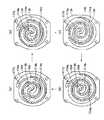
次に、圧縮機100の特徴的作動について図6を用いて述べる。
【0080】
1.最小容量(約20%)運転時(図6(a)参照)
第3、4電磁弁128、134への通電を遮断し、第1、2制御圧Pc1、Pc2を吸入圧Psとする。
【0081】
これにより、コイルスプリング122の弾性力Fsによりスプール116がストッパ120に衝突したまま、ストッパ120がシリンダ115の段付き部115aに衝突するまで弾性力Fsの向きに摺動変位する。ここで、段付き部115aは、ストッパ120の最大変位を規制するストッパ手段を構成するものである。
【0082】
そして、この状態では、第1、2バイパスポート114a、114bが開くように構成されているため、圧縮機100(圧縮機構Cp)の吐出容量が、最大時の約20%となる。
【0083】
2.中間容量(約50%)運転時(図6(b)参照)
第3電磁弁128への通電を遮断し、第4電磁弁へ通電することにより、第1制御圧Pc1を吸入圧Psとし、第2制御圧Pc2を吐出圧Pdとする。
【0084】
これにより、ストッパ120が弾性力Fsに対向してコイルスプリング122を押し縮めるように、スプール166の摺動方向一端側に移動するので、第2バイパスポート114bが閉じた状態となり、圧縮機100(圧縮機構Cp)の吐出容量が、最大時の約50%となる。
【0085】
3.最大容量(100%)運転時(図6(c)参照)
第3、4電磁弁128、134へ通電し、第1、2制御圧Pc1、Pc2を吐出圧Pdとする。
【0086】
これにより、コイルスプリング122を押し縮めるようにスプール116が弾性力Fsの向きと反対の向きに摺動変位するので、第1、2バイパスポート114a、114bが閉じ、圧縮機100(圧縮機構Cp)の吐出容量が、最大容量となる。
【0087】
そして、前提となる形態で述べたように、エンジン500の負荷に応じて圧縮機100の吐出容量を制御すれば、加速性能及び車両燃費を十分に向上させつつ、過度に吐出容量が低下してしまうことを防止することができる。
【0088】
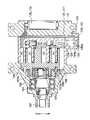
(第2実施形態)
本実施形態は、図7に示すように、第1圧力調整手段123に第1制御圧Pc1を導く冷媒通路(第1通路)126、127と、第2圧力調整手段129に第2制御圧Pc2を導く冷媒通路(第2通路)132、133とを、リアハウジング151と固定スクロール104との間に挟まれたガスケット150にて区画した状態で略平行に設けたものである。
【0089】
すなわち、図7、8に示すように、固定スクロール104の端板部104bのうちリアハウジング151側の面に冷媒通路126、127を構成する溝を形成し、一方、リアハウジング151のうち端板部104b側の面に冷媒通路132、133を構成する溝を形成するとともに、端板部104bの溝及びリアハウジング151の溝の開口側をガスケット150にて閉塞したものである。
【0090】
ここで、ガスケット150とは、リアハウジング151と固定スクロール104とを隙間なく密閉(シール)するものであり、本実施形態では、金属の表裏両面にゴム等の樹脂を被覆したものである。
【0091】
次に、本実施形態の特徴を述べる。
【0092】
ところで、作動室Vcから吐出する冷媒の脈動は吐出室107にて平滑化されるが、脈動を十分に平滑化するためには、吐出室107の容積を十分に大きくする必要がある。
【0093】
ここで仮に、冷媒通路126、127(以下、この冷媒通路を第1冷媒通路126と表記する。)と冷媒通路132、133(以下、この冷媒通路を第2冷媒通路132と表記する。)との両者をリアハウジング151及び固定スクロール104(端板部104b)のいずれか一方側に形成すると、必然的に両通路126、132は、圧縮機の軸方向に対して並列に(図8の紙面方向に並列に)並んでしまうので、吐出室107の容積が小さくなってしまうおそれがある。
【0094】
これに対して、本実施形態によれば、第1、2冷媒通路126、132がガスケット150にて区画された状態で略平行に設けられているので、第1、2冷媒通路126、132が圧縮機の軸方向に対して直列に並ぶこととなり、吐出室107の容積が小さくなってしまうことを防止できる。したがって、圧力脈動を十分に平滑化しつつ、加速性能及び車両燃費を十分に向上させ、かつ、過度に吐出容量が低下してしまうことを防止することができる。
【0095】
なお、本実施形態では、第3、4電磁弁128、134をフロントハウジング102とリアハウジング151との間に配設し、かつ、冷媒通路127、133をリアハウジング151内に設けたが、図9に示すように、第3、4電磁弁128、134をフロントハウジング102と固定スクロール104との間に配設し、かつ、冷媒通路127、133を固定スクロール104内に形成してもよく、また、図10に示すように、第3、4電磁弁128、134及び冷媒通路127、133の両者をリアハウジング151内に設けてもよい。
【0096】
(第3実施形態)
本実施形態は、図11に示すように、第2、3実施形態に係る圧縮機において、ストッパ120をスプール116に向けて押圧する弾性力をストッパ120に作用させるコイルスプリング(弾性手段)140を第2制御室130内に設けたものである。
【0097】
これにより、エンジン500の振動や車両振動により、ストッパ120が第1制御室124(空間124)内で振動する(がたつく)ことを防止できるので、ストッパ120の振動に起因する騒音を未然に防止できる。
【0098】
なお、図11(a)、(b)から明らかなように、最小容量運転時及び中間容量運転時においては、ストッパ120はスプール116とコイルスクリング140とにより挟まれた状態になることにより振動が抑制され、最大容量運転時には、ストッパ120は段付き部115aとコイルスクリング140とにより挟まれた状態になることにより振動が抑制される。
【0099】
(その他の実施形態)
第1実施形態では、最小容量運転時に第2電磁弁118dを閉じていたが、この状態では、第1電磁弁118cを開いているので、第2電磁弁118dを開くように制御しても実用上問題ない。
【0100】
また、上述の実施形態では、スロットルバルブの開度を検出することにより、エンジン500の負荷を検出したが、エンジン500の回転数変化及び吸入負圧等その他のパラメータからエンジン500の負荷を検出してもよい。
【0101】
また、本発明に係る圧縮機は、作動室Vcがその体積を拡大縮小させながら移動していくタイプの圧縮機に対して適用することができるものであるから、ローリングピストン型やべーン型等の圧縮機に対しても適用することができる。
【0102】
また、上述の実施形態では、圧力制御手段(電磁弁等)が圧縮機に内蔵されていたが、圧力制御手段(電磁弁等)を固定スクロール104に外付けしてもよい。
【図面の簡単な説明】
【図1】 冷凍サイクルの模式図である。
【図2】 本発明の前提となる形態に係る圧縮機の断面図である。
【図3】 旋回スクロールの作動を示す説明図である。
【図4】 図1のA−A断面図である。
【図5】 本発明の前提となる施形態に係る圧縮機におけるスプールの作動を示す説明図である。
【図6】 本発明の第1実施形態に係る圧縮機におけるスプールの作動を示す説明図である。
【図7】 本発明の第2実施形態に係る圧縮機の断面図である。
【図8】 図7のB−B断面図である。
【図9】 本発明の第2実施形態の変形例に係る圧縮機の断面図である。
【図10】 本発明の第2実施形態の変形例に係る圧縮機の断面図である。
【図11】 本発明の第3実施形態に係る圧縮機におけるスプールの作動を示す説明図である。
【符号の説明】
104 固定スクロール
105 旋回スクロール
114a、114b第1、第2バイパスポート
114b 第2バイパスポート
115ガイドシリンダボア
116 スプール弁体
116a〜116c弁部
116d、116eロッド部
120 ストッパ
122、140コイルスプリング
123、129第1、第2圧力調整手段
124、130第1、第2制御圧室
125、131固定絞り
128、134第3、第4電磁弁
150ガスケット[0001]
BACKGROUND OF THE INVENTION
The present invention relates to a variable displacement scroll compressor, and is effective when applied to a compressor of a refrigeration cycle for a vehicle.
[0002]
[Prior art]
As a variable capacity scroll type compressor for a refrigeration cycle, for example, in the invention described in Japanese Patent Application Laid-Open No. 9-296787, the working chamber and the suction side during the compression stroke are balanced by the balance between the elastic force of the coil spring and the suction pressure. The spool valve that opens and closes the bypass hole that communicates with each other is opened and closed.
[0003]
However, in the invention described in the above publication, since the bypass hole is opened and closed by the balance between the elastic force of the coil spring and the suction pressure, the bypass hole is opened and closed according to the heat load of the refrigeration cycle (pressure in the evaporator). It becomes.
[0004]
By the way, the compressor of the refrigeration cycle for a vehicle is operated by obtaining power from a traveling engine (hereinafter abbreviated as “engine”). Therefore, when the engine load is high during climbing or acceleration, the discharge capacity of the compressor In order to improve the acceleration performance and the fuel consumption rate (vehicle fuel consumption), it is desirable to reduce the engine load by reducing the engine pressure.
[0005]
On the other hand, in the invention described in the above publication, the bypass hole that connects the working chamber and the suction side during the compression stroke is opened and closed by the balance between the elastic force of the coil spring and the suction pressure. Accordingly, the discharge capacity cannot be changed according to the engine, and the engine cannot be appropriately controlled. Therefore, it is practically impossible to improve the acceleration performance and the vehicle fuel consumption.
[0006]
In response to such a demand, for example, in a variable capacity swash plate compressor described in Japanese Patent Application Laid-Open No. 2-249717, the swash plate inclination is controlled by controlling the pressure in the swash plate chamber based on the engine load. The discharge capacity is changed by changing the angle.
[0007]
[Problems to be solved by the invention]
Incidentally, the inventors controlled the pressure in the swash plate chamber according to the engine load as in the invention described in JP-A-2-249717. The vehicle fuel consumption could not be sufficiently improved.
[0008]
Then, the following points were found when investigating the cause of the inclination angle (discharge capacity) not changing rapidly in response to fluctuations in engine load.
[0009]
That is, in the invention described in JP-A-2-249717, the inclination angle of the swash plate is controlled by balancing the compression reaction force and the pressure in the swash plate chamber, but the compression reaction force is linked to the discharge pressure. The pressure in the swash plate chamber is controlled by adjusting the suction pressure and the discharge pressure with valve means such as an electromagnetic valve and introducing the pressure into the swash plate chamber.
[0010]
Here, since both the suction pressure and the discharge pressure fluctuate due to the heat load of the refrigeration cycle, even if the valve means is controlled according to the engine load, the force (compression reaction) actually acting on the swash plate is controlled. Force and pressure in the swash plate chamber) are strongly influenced by the heat load of the refrigeration cycle. Therefore, even if the valve means is controlled in accordance with the engine load, the inclination angle (discharge capacity) cannot be changed rapidly with respect to fluctuations in the engine load.
[0011]
Further, although the acceleration performance can be improved to the extent that the discharge capacity is controlled in two stages of the maximum capacity and the minimum capacity, the discharge refrigerant flow rate is reduced, so that the refrigerating capacity is lowered.
[0012]
In view of the above points, an object of the present invention is to provide a compressor that can be controlled to a required discharge capacity according to usage conditions, such as quickly changing the discharge capacity in response to fluctuations in engine load. To do.
[0013]
[Means for Solving the Problems]
In order to achieve the above object, the present invention claims1In the described invention,A compression mechanism having a fixed scroll (104) and a orbiting scroll (105), and enlarging and reducing the working chamber (Vc) for sucking and compressing fluid by orbiting the orbiting scroll (105) with respect to the fixed scroll (104). (Cp), first and second bypass holes (114a, 114b) that connect the working chamber (Vc) in at least two states among the working chambers (Vc) during the compression stroke and the suction side of the compression mechanism (Cp). ), And a variable capacity scroll compressor including a valve body (116) that opens and closes the first and second bypass holes (114a, 114b) from the one end side in the movable direction of the valve body (116). The elastic means (122) for applying an elastic force to the (116) and the other end in the movable direction of the valve body (116) are arranged to be displaceable in a direction parallel to the movable direction of the valve body (116). A stopper (120) that regulates the movable range of the valve body (116), the other end side in the movable direction of the valve body (116), and the other end side of the stopper (120) in the movable direction of the valve body (116). On the opposite side, the first pressure adjusting means (123) that operates by switching the discharge pressure of the compression mechanism (Cp) and the suction pressure of the compression mechanism (Cp), and the movable body of the valve body (116) of the stopper (120). On the opposite side to the side facing the other end in the direction, there is provided a second pressure adjusting means (129) for switching and acting the discharge pressure and the suction pressure, and a working chamber in a state communicating with the first bypass hole (114a) ( The volume of Vc) is larger than the volume (Vc) of the working chamber in a state communicating with the second bypass hole (114b),
When the discharge capacity of the compression mechanism (Cp) is set to the maximum capacity, the first pressure adjusting means (123) causes the valve body (116) of the valve body (116) to move in the movable direction other end side and the stopper (120). The discharge pressure is applied to the side facing the other end side in the movable direction, and the second pressure adjusting means (129) is opposite to the side facing the other end side in the movable direction of the valve body (116) in the stopper (120). By applying the discharge pressure to the side, the valve body (116) is displaced in the direction opposite to the direction of the elastic force, and both the first and second bypass holes (114a, 114b) are closed,
When the discharge capacity of the compression mechanism (Cp) is set to an intermediate capacity, the first pressure adjusting means (123) causes the valve body (116) of the valve body (116) to move in the movable direction other end side and the stopper (120). The suction pressure is applied to the side facing the other end in the movable direction, and the second pressure adjusting means (129) is opposite to the side of the stopper (120) facing the other end in the movable direction of the valve body (116). Displacement of the valve body (116) is restricted by the stopper (120) displaced in the direction opposite to the direction of the elastic force by applying the discharge pressure to the side, and the first bypass hole (114a) is opened. Both close the second bypass hole (114b)
When the discharge capacity of the compression mechanism (Cp) is set to the minimum capacity, the first pressure adjusting means (123) causes the valve body (116) of the valve body (116) to move in the movable direction other end side and the stopper (120). The suction pressure is applied to the side facing the other end in the movable direction, and the second pressure adjusting means (129) is opposite to the side of the stopper (120) facing the other end in the movable direction of the valve body (116). By applying the suction pressure to the side, the stopper (120) displaced in the direction of the elastic force regulates the displacement of the valve body (116), and the first and second bypass holes (114a, 114b) Open both sidesIt is characterized by that.
[0014]
Thereby, in this invention,Of the elastic means (122)Elastic force andActs on the other end of the valve body (116) in the movable direction and the stopper (120).Since the valve body (116) is moved in balance with the pressure, the valve body (116) can be moved without being affected by the thermal load of the cycle if the elastic force is sufficiently increased. .
[0015]
Therefore, if the pressure adjusting means (118, 123, 129) is operated so as to reduce the discharge capacity of the variable displacement scroll compressor when the engine load during acceleration or climbing is large, the engine load is reduced. It becomes possible to rapidly decrease and change the discharge capacity with respect to the fluctuations. As a result, it is possible to prevent the discharge capacity from being excessively lowered while sufficiently improving the vehicle fuel consumption.
[0016]
In the present invention, since the working chamber (Vc) in the compression stroke has a plurality of bypass holes (114) for communicating between the working chamber (Vc) in at least two states and the suction side, Discharge capacity of at least minimum capacity, intermediate capacity and maximum capacity3It can be changed to one state.
[0017]
In the invention according to
[0019]
In invention of Claim 3,The variable capacity scroll compressor according to
[0023]
Claim4In the invention described in4. The variable capacity scroll compressor according to claim 3, further being fixed to the fixed scroll (104) via the gasket (150) and smoothing the pulsation of the fluid discharged from the working chamber (Vc). A rear housing (151) that forms a discharge chamber (107) to be formed, and at least a part of the first discharge side communication path (126) and the first suction side communication path (127) is a second discharge side communication path ( 132) and at least a part of the second suction side communication path (133),It is characterized by being provided substantially parallel in a state partitioned by a gasket (150).
[0024]
As a result, the first and second passages (126, 127, 132, 133) are arranged in series with respect to the axial direction of the variable displacement scroll compressor, so that the volume of the discharge chamber (107) is reduced. Can be prevented. Therefore, the pressure pulsation is sufficiently smoothed, and the acceleration performance and the vehicle fuel consumption are sufficiently improved, for example, the acceleration performance is improved as the minimum capacity operation, or the intermediate capacity operation is performed. As a result, the discharge capacity can be selected in accordance with the user-friendliness, such as achieving both fuel efficiency and air conditioning capability.
[0025]
Claim5In the invention described inThe variable capacity scroll compressor according to any one of claims 1 to 4, further comprising a stopper (120) disposed on a side opposite to a side facing the other end of the valve body (116) in the movable direction. AndAnd stopper-side elastic means (140) for applying an elastic force for pressing the stopper (120) toward the valve body (116).
[0026]
Accordingly, the stopper (120) can be prevented from vibrating (rattle), so that noise caused by the vibration of the stopper (120) can be prevented and acceleration performance and While improving the vehicle fuel efficiency sufficiently, for example, it is possible to select the discharge capacity in accordance with the convenience of use, such as improving the acceleration performance as a minimum capacity operation, or achieving both the fuel efficiency and the air conditioning capacity as an intermediate capacity operation. .
[0027]
Claim6In the invention described in claim 1, the driving force is obtained from the vehicle driving source (500) to operate.1Or5The variable-capacity scroll compressor (100) according to any one of the above, a drive load detection means (600) for detecting a drive load of the vehicle travel drive source (500), and a drive load detection means (600) When the detected driving load is equal to or greater than a predetermined load, at least one of the first and second pressure adjusting means (123, 129) is operated to reduce the discharge capacity of the variable displacement scroll compressor (100). Control means (700)Refrigeration cycle for vehiclesIt is characterized by.
[0028]
As a result, while the acceleration performance and vehicle fuel efficiency are sufficiently improved, for example, the acceleration performance can be improved as a minimum capacity operation, or the discharge capacity can be adjusted to the user's convenience such as achieving both the fuel efficiency and the air conditioning capacity as an intermediate capacity operation. You can make a choice.
[0029]
Incidentally, the reference numerals in parentheses of each means described above are an example showing the correspondence with the specific means described in the embodiments described later.
[0030]
(Form which is the premise of the present invention)
BookIn the embodiment, a variable capacity scroll compressor (hereinafter abbreviated as a compressor) according to the present invention is applied to a vehicle refrigeration cycle (vehicle air conditioner), and FIG. , Abbreviated as a cycle).
[0031]
100 isBookIn the compressor according to the embodiment,
[0032]
The
[0033]
In addition, 600 is a load of engine 500 (BookIn the embodiment, it is a drive load sensor (drive load detection means) that detects the opening degree of a throttle valve (not shown), and 700 is a pressure that will be described later according to a program set in advance based on the detection value of the
[0034]
Next, the structure of the
[0035]
FIG. 2 shows a cross section of the
[0036]
Further, in a space formed by the fixed
[0037]
By the way,BookIn the embodiment, the
[0038]
Then, the
[0039]
[0040]
The
[0041]
By the way, a bypass port (bypass hole) 114 that connects the working chamber Vc and the
[0042]
Incidentally, in the scroll compressor, as shown in FIG. 3, as the
[0043]
When the
[0044]
2 and 4, a guide cylinder bore (columnar hole) 115 extending in a straight line is formed in the
[0045]
The
[0046]
Incidentally,
[0047]
By the way, the sliding direction of the spool 116 (the arrow direction in FIG. 2) one end side (BookIn the form, a coil spring (elastic means) 118f that exerts an elastic force that presses the
[0048]
On the other hand, the other end side in the sliding direction of the spool 116 (BookIn the embodiment, as shown in FIG. 2, the discharge pressure Pd of the compression mechanism Cp is adjusted to be reduced, and the adjusted pressure (hereinafter, this adjusted pressure is referred to as the control pressure Pc), as shown in FIG. Pressure adjusting means 118 is provided to act on the other end side in the sliding direction of the
[0049]
Hereinafter, the other side of the
[0050]
The pressure adjusting means 118 includes first and
[0051]
The
[0052]
Incidentally, the
[0053]
[0054]
Next, the characteristic operation of the
[0055]
1. During minimum capacity (approximately 20%) operation (see Fig. 5 (a))
The current supply to the first and
[0056]
As a result, the control pressure Pc in the
[0057]
In this state, since the first and
[0058]
2. During intermediate capacity (approx. 50%) operation (see Fig. 5 (b))
By energizing the first and
[0059]
As a result, the valve closing force increases by an amount corresponding to the set differential pressure of the
[0060]
In this state, since the
[0061]
3. During maximum capacity (100%) operation (see Fig. 5 (c))
The first and
[0062]
Thereby, since the control pressure Pc becomes the discharge pressure Pd, the valve closing force exceeds the valve opening force, and the
[0063]
In this state, since the first and
[0064]
next,BookThe characteristics of the form are described.
[0065]
BookAccording to the embodiment, since the
[0066]
Therefore, when the pressure adjustment means 118 (first and second
[0067]
Further, when the discharge capacity of the
[0068]
In addition, when the
[0069]
Further, since the discharge capacity of the
[0070]
Further, as shown in FIG. 4, by arranging the
[0071]
In the present embodiment, the first
[0072]
(First embodiment)
In the present embodiment, as shown in FIG. 6, the
[0073]
Hereinafter, the characteristic part of this embodiment is demonstrated based on FIG. Other than the pressure adjusting means for controlling the movement (sliding) of the
[0074]
An elastic force that presses the
[0075]
On the other hand, on the other end side in the sliding direction of the spool 116 (lower side in FIG. 6 in this embodiment), the discharge pressure Pd and the suction pressure Ps are switched, and the switched control pressure is changed to the sliding direction of the
[0076]
Here, the first pressure adjusting means 123 has a first fixed
[0077]
[0078]
Here, the second pressure adjusting means 129 includes a second fixed
[0079]
Next, a characteristic operation of the
[0080]
1. During minimum capacity (approximately 20%) operation (see Fig. 6 (a))
The current supply to the third and
[0081]
Thus, the
[0082]
In this state, since the first and
[0083]
2. During intermediate capacity (about 50%) operation (see Fig. 6 (b))
By energizing the
[0084]
Accordingly, the
[0085]
3. During maximum capacity (100%) operation (see Fig. 6 (c))
The third and
[0086]
As a result, the
[0087]
AndPremiseAs described in the embodiment, when the discharge capacity of the
[0088]
(No.2Embodiment)
In the present embodiment, as shown in FIG. 7, the first control pressure Pc1 is applied to the first pressure adjusting means 123.TheThe second control pressure is applied to the refrigerant passages (first passages) 126 and 127 to be guided and the second pressure adjusting means 129.Pc2Refrigerant passages (second passages) 132 and 133 are provided in a substantially parallel manner in a state of being partitioned by a
[0089]
That is, as shown in FIGS. 7 and 8, grooves constituting the
[0090]
Here, the
[0091]
Next, features of the present embodiment will be described.
[0092]
By the way, the pulsation of the refrigerant discharged from the working chamber Vc is smoothed in the
[0093]
Here, it is assumed that the
[0094]
On the other hand, according to the present embodiment, the first and second
[0095]
In the present embodiment, the third and
[0096]
(No.3Embodiment)
As shown in FIG. 11, the present embodiment includes a coil spring (elastic means) 140 that acts on the
[0097]
Accordingly, the
[0098]
11A and 11B, during the minimum capacity operation and the intermediate capacity operation, the
[0099]
(Other embodiments)
In the first embodiment, the second
[0100]
In the above-described embodiment, the load of the
[0101]
Further, the compressor according to the present invention can be applied to a compressor of a type in which the working chamber Vc moves while enlarging or reducing the volume thereof, so that a rolling piston type or a vane type can be used. The present invention can also be applied to a compressor such as the above.
[0102]
In the above-described embodiment, the pressure control means (electromagnetic valve or the like) is built in the compressor, but the pressure control means (electromagnetic valve or the like) may be externally attached to the fixed
[Brief description of the drawings]
FIG. 1 is a schematic diagram of a refrigeration cycle.
FIG. 2 of the present inventionPremiseIt is sectional drawing of the compressor which concerns on a form.
FIG. 3 is an explanatory diagram showing the operation of the orbiting scroll.
4 is a cross-sectional view taken along the line AA in FIG.
FIG. 5 of the present inventionPremiseIt is explanatory drawing which shows the action | operation of the spool in the compressor which concerns on embodiment.
FIG. 6 shows the first of the present invention.1It is explanatory drawing which shows the action | operation of the spool in the compressor which concerns on embodiment.
FIG. 7 shows the first of the present invention.2It is sectional drawing of the compressor which concerns on embodiment.
8 is a cross-sectional view taken along the line BB in FIG.
FIG. 9 shows the first of the present invention.2It is sectional drawing of the compressor which concerns on the modification of embodiment.
FIG. 10 shows the first of the present invention.2It is sectional drawing of the compressor which concerns on the modification of embodiment.
FIG. 11 shows the first of the present invention.3It is explanatory drawing which shows the action | operation of the spool in the compressor which concerns on embodiment.
[Explanation of symbols]
104 Fixed scroll
105 Orbiting scroll
114a, 114b First and second bypass ports
114b second bypass port
115 Guide cylinder bore
116 Spool valve body
116a to 116c Valve
116d, 116e Rod part
120 stopper
122, 140 coil spring
123, 129 First and second pressure adjusting means
124, 130 First and second control pressure chambers
125, 131 Fixed aperture
128, 134 3rd, 4th solenoid valve
150 gasket
Claims (6)
Translated fromJapanese前記弁体(116)の可動方向一端側から、前記弁体(116)に弾性力を作用させる弾性手段(122)と、
前記弁体(116)の可動方向他端側において、前記弁体(116)の可動方向と平行な方向に変位可能に配設され、前記弁体(116)の可動範囲を規制するストッパ(120)と、
前記弁体(116)のうち前記可動方向他端側、および、前記ストッパ(120)のうち前記弁体(116)の前記可動方向他端側に対向する側に、前記圧縮機構(Cp)の吐出圧及び前記圧縮機構(Cp)の吸入圧を切り替えて作用させる第1圧力調整手段(123)と、
前記ストッパ(120)のうち前記弁体(116)の前記可動方向他端側に対向する側と反対側に、前記吐出圧及び前記吸入圧を切り替えて作用させる第2圧力調整手段(129)とを備え、
前記第1バイパス孔(114a)に連通する状態の作動室(Vc)の体積は、前記第2バイパス孔(114b)に連通する状態の作動室の体積(Vc)よりも大きく、
前記圧縮機構(Cp)の吐出容量を最大容量とするときは、
前記第1圧力調整手段(123)が、前記弁体(116)の前記可動方向他端側および前記ストッパ(120)のうち前記弁体(116)の前記可動方向他端側に対向する側に前記吐出圧を作用させるとともに、前記第2圧力調整手段(129)が、前記ストッパ(120)のうち前記弁体(116)の前記可動方向他端側に対向する側と反対側に前記吐出圧を作用させることによって、前記弾性力の向きと反対の向きに前記弁体(116)を変位させて、第1、第2バイパス孔(114a、114b)の双方を閉じ、
前記圧縮機構(Cp)の吐出容量を中間容量とするときは、
前記第1圧力調整手段(123)が、前記弁体(116)の前記可動方向他端側および前記ストッパ(120)のうち前記弁体(116)の前記可動方向他端側に対向する側に前記吸入圧を作用させるとともに、前記第2圧力調整手段(129)が、前記ストッパ(120)のうち前記弁体(116)の前記可動方向他端側に対向する側と反対側に前記吐出圧を作用させることによって、前記弾性力の向きと反対の向きに変位させた前記ストッパ(120)にて、前記弁体(116)の変位を規制して、前記第1バイパス孔(114a)を開くともに、前記第2バイパス孔(114b)を閉じ、
前記圧縮機構(Cp)の吐出容量を最小容量とするときは、
前記第1圧力調整手段(123)が、前記弁体(116)の前記可動方向他端側および前記ストッパ(120)のうち前記弁体(116)の前記可動方向他端側に対向する側に前記吸入圧を作用させるとともに、前記第2圧力調整手段(129)が、前記ストッパ(120)のうち前記弁体(116)の前記可動方向他端側に対向する側と反対側に前記吸入圧を作用させることによって、前記弾性力の向きに変位させた前記ストッパ(120)にて、前記弁体(116)の変位を規制して、前記第1、第2バイパス孔(114a、114b)の双方を開くことを特徴とする可変容量スクロール型圧縮機。The working chamber (Vc) for sucking and compressing fluid is enlarged and reduced by having the fixed scroll (104) and the orbiting scroll (105), and orbiting the orbiting scroll (105) with respect to the fixed scroll (104). A compression mechanism (Cp), andfirst and second bypass holes for communicating at least two types of working chambers (Vc) among the working chambers (Vc) during the compression stroke and the suction side of the compression mechanism (Cp) (114a, 114b ), and a variable capacity scroll compressor comprising a valve body (116) for opening and closingthe first and second bypass holes (114a, 114b ),
Elastic means (122) for applying an elastic force to thevalve body (116) from one end side in the movable direction of the valve body (116) ;
A stopper (120) is disposed on the other end side in the movable direction of the valve body (116) so as to be displaceable in a direction parallel to the movable direction of the valve body (116) and restricts the movable range of the valve body (116). )When,
The valve body (116)prior Symbol movableDirection other end sideof, and, onthe side facing the movable direction other end side of the valve body (116) of the stopper (120), said compression mechanism (Cp ) And a first pressure adjusting means (123) for switching and operating the discharge pressure of the compression mechanism (Cp),
A second pressure adjusting means (129) for switching and operating the discharge pressure and the suction pressure ona side of the stopper (120)opposite to the opposite side of the valve body (116) inthe movable direction ; equipped witha,
The volume of the working chamber (Vc) in communication with the first bypass hole (114a) is larger than the volume (Vc) of the working chamber in communication with the second bypass hole (114b),
When the discharge capacity of the compression mechanism (Cp) is the maximum capacity,
The first pressure adjusting means (123) is on the other end side in the movable direction of the valve body (116) and on the side of the stopper (120) facing the other end side in the movable direction of the valve body (116). The discharge pressure is applied, and the second pressure adjusting means (129) is disposed on the stopper (120) on the opposite side of the valve body (116) from the opposite side of the movable direction. To displace the valve body (116) in a direction opposite to the direction of the elastic force, and close both the first and second bypass holes (114a, 114b),
When the discharge capacity of the compression mechanism (Cp) is an intermediate capacity,
The first pressure adjusting means (123) is on the other end side in the movable direction of the valve body (116) and on the side of the stopper (120) facing the other end side in the movable direction of the valve body (116). While applying the suction pressure, the second pressure adjusting means (129) causes the discharge pressure on the opposite side of the stopper (120) to face the other end of the valve body (116) in the movable direction. Is applied to restrict the displacement of the valve body (116) by the stopper (120) displaced in the direction opposite to the direction of the elastic force, thereby opening the first bypass hole (114a). Both close the second bypass hole (114b),
When the discharge capacity of the compression mechanism (Cp) is set to the minimum capacity,
The first pressure adjusting means (123) is on the other end side in the movable direction of the valve body (116) and on the side of the stopper (120) facing the other end side in the movable direction of the valve body (116). While applying the suction pressure, the second pressure adjusting means (129) is disposed on the side of the stopper (120) opposite to the side facing the other end of the valve body (116) in the movable direction. By acting, the displacement of the valve body (116) is regulated by the stopper (120) displaced in the direction of the elastic force, and the first and second bypass holes (114a, 114b) A variable capacity scroll compressor characterizedby opening both sides .
前記弁体部は、前記端板部(104b)に形成されて前記第1、第2バイパス孔(114a、114b)に連通する円柱状の穴(115)に対して、摺動可能に配設されたスプール弁体(116)で構成され、The valve body is slidably disposed in a cylindrical hole (115) formed in the end plate (104b) and communicating with the first and second bypass holes (114a, 114b). A spool valve body (116) made of
さらに、前記スプール弁体(116)は、前記第1、第2バイパス孔(114a、114b)を開閉する複数の弁部(116a、116b、116c)、および、前記複数の弁部(116a、116b、116c)を連結するロッド部(116d、116e)を有し、Further, the spool valve body (116) includes a plurality of valve portions (116a, 116b, 116c) for opening and closing the first and second bypass holes (114a, 114b), and the plurality of valve portions (116a, 116b). , 116c) and rod portions (116d, 116e),
前記複数の弁部(116a、116b、116c)の外径寸法は、前記円柱状の穴(115)の内径寸法と略等しく形成され、The outer diameter dimensions of the plurality of valve portions (116a, 116b, 116c) are substantially equal to the inner diameter dimension of the cylindrical hole (115),
前記ロッド部(116d、116e)の外形寸法は、前記円柱状の穴(115)の内径寸法より小さく形成され、The rod part (116d, 116e) has an outer dimension smaller than an inner diameter dimension of the cylindrical hole (115),
前記円柱状の穴(115)と前記ロッド部(116d、116e)との隙間には、前記第1、第2バイパス孔(114a、114b)から前記吸入側へ流体を流す流体通路が形成されていることを特徴とする請求項1に記載の可変容量スクロール形圧縮機。In the gap between the cylindrical hole (115) and the rod portion (116d, 116e), a fluid passage is formed to flow fluid from the first and second bypass holes (114a, 114b) to the suction side. The variable capacity scroll compressor according to claim 1, wherein
前記第1圧力調整手段(123)は、固定絞り(125)を介して前記圧縮機構(Cp)の吐出側と前記第1制御圧室(124)とを連通させる第1吐出側連通路(126)、前記圧縮機構(Cp)の吸入側と前記第1制御圧室(124)とを連通させる第1吸入側連通路(127)、および、前記第1吸入側連通路(127)を開閉する電磁弁(128)を有し、The first pressure adjusting means (123) is configured to communicate a discharge side of the compression mechanism (Cp) with the first control pressure chamber (124) via a fixed throttle (125). ), And opens and closes the first suction side communication path (127) for communicating the suction side of the compression mechanism (Cp) and the first control pressure chamber (124), and the first suction side communication path (127). Having a solenoid valve (128),
前記第2圧力調整手段(129)は、固定絞り(131)を介して前記圧縮機構(Cp)の吐出側と前記第2制御圧室(130)とを連通させる第2吐出側連通路(132)、前記圧縮機構(Cp)の吸入側と前記第2制御圧室(130)とを連通させる第2吸入側連通路(133)、および、前記第2吸入側連通路(133)を開閉する電磁弁(134)を有することを特徴とする請求項1または2に記載の可変容量スクロール型圧縮機。The second pressure adjusting means (129) is configured to communicate a discharge side of the compression mechanism (Cp) with the second control pressure chamber (130) via a fixed throttle (131). ), And opens and closes the second suction side communication path (133) for communicating the suction side of the compression mechanism (Cp) and the second control pressure chamber (130), and the second suction side communication path (133). The variable capacity scroll compressor according to claim 1 or 2, further comprising a solenoid valve (134).
前記第1吐出側連通路(126)および前記第1吸入側連通路(127)の少なくとも一部が、前記第2吐出側連通路(132)および前記第2吸入側連通路(133)の少なくとも一部に対して、前記ガスケット(150)にて区画された状態で略平行に設けられていることを特徴とする請求項3に記載の可変容量スクロール型圧縮機。Further, a rear housing that is fixed to the fixed scroll (104) via a gasket (150) and forms a discharge chamber (107) that smoothes pulsation of fluid discharged from the working chamber (Vc). (151)
At least a part of the first discharge side communication path (126) and the first suction side communication path (127) is at least part of the second discharge side communication path (132) and the second suction side communication path (133). The variable capacity scroll compressor according to claim3 , wherein a part of the variable capacity scroll compressor is provided substantially in parallel with apart of the gasket (150).
前記可変容量スクロール型圧縮機(100)から吐出する冷媒を冷却する放熱器(200)と、
前記放熱器(200)から流出する冷媒を減圧する減圧器(300)と、
前記減圧器(300)にて減圧された冷媒を蒸発させるとともに、その蒸発した冷媒を前記可変容量スクロール型圧縮機(100)の吸入側に向けて流出させる蒸発器(400)と、
前記車両走行用駆動源(500)の駆動負荷を検出する駆動負荷検出手段(600)と、
前記駆動負荷検出手段(600)により検出された駆動負荷が所定負荷以上となったときに、前記第1、2圧力調整手段(123、129)のうち少なくとも一方を作動させて前記可変容量スクロール型圧縮機(100)の吐出容量を縮小させる制御手段(700)とを備えることを特徴とする車両用冷凍サイクル。The variable capacity scroll compressor (100) according to anyone of claims1 to 5 , wherein the variable displacement scroll compressor (100) is operated by obtaining a driving force from a vehicle driving source (500).
A radiator (200) for cooling the refrigerant discharged from the variable capacity scroll compressor (100);
A decompressor (300) for decompressing the refrigerant flowing out of the radiator (200);
An evaporator (400) that evaporates the refrigerant decompressed by the decompressor (300) and causes the evaporated refrigerant to flow toward the suction side of the variable capacity scroll compressor (100);
Drive load detection means (600) for detecting a drive load of the vehicle drive source (500);
When the driving load detected by the driving load detecting means (600) becomes equal to or greater than a predetermined load, at least one of the first and second pressure adjusting means (123, 129) is operated to make the variable displacement scroll type. A vehicle refrigeration cycle comprising: a control means (700) for reducing the discharge capacity of the compressor (100).
Priority Applications (1)
| Application Number | Priority Date | Filing Date | Title |
|---|---|---|---|
| JP19479499AJP4258069B2 (en) | 1999-05-20 | 1999-07-08 | Variable capacity scroll compressor and refrigeration cycle for vehicle |
Applications Claiming Priority (3)
| Application Number | Priority Date | Filing Date | Title |
|---|---|---|---|
| JP11-140682 | 1999-05-20 | ||
| JP14068299 | 1999-05-20 | ||
| JP19479499AJP4258069B2 (en) | 1999-05-20 | 1999-07-08 | Variable capacity scroll compressor and refrigeration cycle for vehicle |
Publications (2)
| Publication Number | Publication Date |
|---|---|
| JP2001032787A JP2001032787A (en) | 2001-02-06 |
| JP4258069B2true JP4258069B2 (en) | 2009-04-30 |
Family
ID=26473125
Family Applications (1)
| Application Number | Title | Priority Date | Filing Date |
|---|---|---|---|
| JP19479499AExpired - Fee RelatedJP4258069B2 (en) | 1999-05-20 | 1999-07-08 | Variable capacity scroll compressor and refrigeration cycle for vehicle |
Country Status (1)
| Country | Link |
|---|---|
| JP (1) | JP4258069B2 (en) |
- 1999
- 1999-07-08JPJP19479499Apatent/JP4258069B2/ennot_activeExpired - Fee Related
Also Published As
| Publication number | Publication date |
|---|---|
| JP2001032787A (en) | 2001-02-06 |
Similar Documents
| Publication | Publication Date | Title |
|---|---|---|
| JP3767129B2 (en) | Variable capacity compressor | |
| JPH0744775Y2 (en) | Compressor capacity control device | |
| JP3728387B2 (en) | Control valve | |
| JPH0861269A (en) | Scroll type compressor | |
| JP4479504B2 (en) | Variable capacity compressor | |
| EP1039129A2 (en) | Device and method for controlling displacement of variable displacement compressor | |
| JP4152674B2 (en) | Capacity control valve for variable capacity compressor | |
| US6089830A (en) | Multi-stage compressor with continuous capacity control | |
| KR101194431B1 (en) | Variable capacity compressor | |
| JP3707242B2 (en) | Variable capacity compressor | |
| US20060165534A1 (en) | Displacement control valve for variable displacement compressor | |
| JP4122736B2 (en) | Control valve for variable capacity compressor | |
| US6079952A (en) | Continuous capacity control for a multi-stage compressor | |
| JP4258069B2 (en) | Variable capacity scroll compressor and refrigeration cycle for vehicle | |
| JP4412186B2 (en) | Variable capacity compressor | |
| JP2946711B2 (en) | Variable capacity swinging swash plate type compressor | |
| JP4035650B2 (en) | Compressor | |
| JP3792939B2 (en) | Variable displacement compressor and displacement control valve | |
| JPH0247275Y2 (en) | ||
| JP4031128B2 (en) | Swash plate type variable capacity compressor | |
| JP3993998B2 (en) | Variable capacity gas compressor | |
| JP4173073B2 (en) | Control valve for variable capacity compressor | |
| US20030108432A1 (en) | Variable displacement type compressor, air conditioner with the variable displacement type compressor, and method for controlling displacement in the variable displacement type compressor | |
| JPS611887A (en) | Rotary compressor | |
| JP4031140B2 (en) | Swash plate type variable capacity compressor |
Legal Events
| Date | Code | Title | Description |
|---|---|---|---|
| A621 | Written request for application examination | Free format text:JAPANESE INTERMEDIATE CODE: A621 Effective date:20050822 | |
| A977 | Report on retrieval | Free format text:JAPANESE INTERMEDIATE CODE: A971007 Effective date:20080731 | |
| A131 | Notification of reasons for refusal | Free format text:JAPANESE INTERMEDIATE CODE: A131 Effective date:20080826 | |
| A521 | Written amendment | Free format text:JAPANESE INTERMEDIATE CODE: A523 Effective date:20081021 | |
| TRDD | Decision of grant or rejection written | ||
| A01 | Written decision to grant a patent or to grant a registration (utility model) | Free format text:JAPANESE INTERMEDIATE CODE: A01 Effective date:20090113 | |
| A01 | Written decision to grant a patent or to grant a registration (utility model) | Free format text:JAPANESE INTERMEDIATE CODE: A01 | |
| A61 | First payment of annual fees (during grant procedure) | Free format text:JAPANESE INTERMEDIATE CODE: A61 Effective date:20090126 | |
| FPAY | Renewal fee payment (event date is renewal date of database) | Free format text:PAYMENT UNTIL: 20120220 Year of fee payment:3 | |
| R150 | Certificate of patent or registration of utility model | Free format text:JAPANESE INTERMEDIATE CODE: R150 | |
| FPAY | Renewal fee payment (event date is renewal date of database) | Free format text:PAYMENT UNTIL: 20130220 Year of fee payment:4 | |
| FPAY | Renewal fee payment (event date is renewal date of database) | Free format text:PAYMENT UNTIL: 20140220 Year of fee payment:5 | |
| R250 | Receipt of annual fees | Free format text:JAPANESE INTERMEDIATE CODE: R250 | |
| LAPS | Cancellation because of no payment of annual fees |